Embed Size (px)
Citation preview

Surface Simplification using Quadric Error Metrics
Guowei Wu

Surface Simplification
Triangulated surface model Several types of simplification techniques
– Vertex Decimation– Vertex Clustering– Iterative Edge Contraction– Pair Contraction (QEM)
Surface Simplification
Limitation of other methods:– Vertex Decimation: maintain mesh topology,
assume manifold model geometry– Vertex Clustering: poor control on simplification
process, low quality– Edge Contraction: no aggregation, assume
manifold model geometry.
Surface Simplification
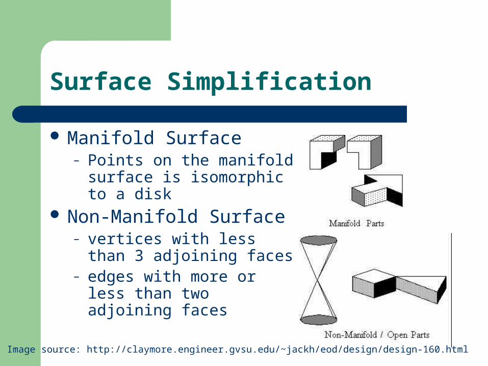
Manifold Surface– Points on the manifold
surface is isomorphic to a disk
Non-Manifold Surface– vertices with less than 3
adjoining faces – edges with more or less
than two adjoining faces
Image source: http://claymore.engineer.gvsu.edu/~jackh/eod/design/design-160.html
Model Boundary Representation
Manifold– Half-Edge data structure (directional edge)– Winged-Edge data structure (every edge
connects to exactly two faces, one on each side.)
Non-Manifold– Radial-Edge data structure (edges can connect to
arbitrarily many faces)
Edge Contraction vs Pair Contraction
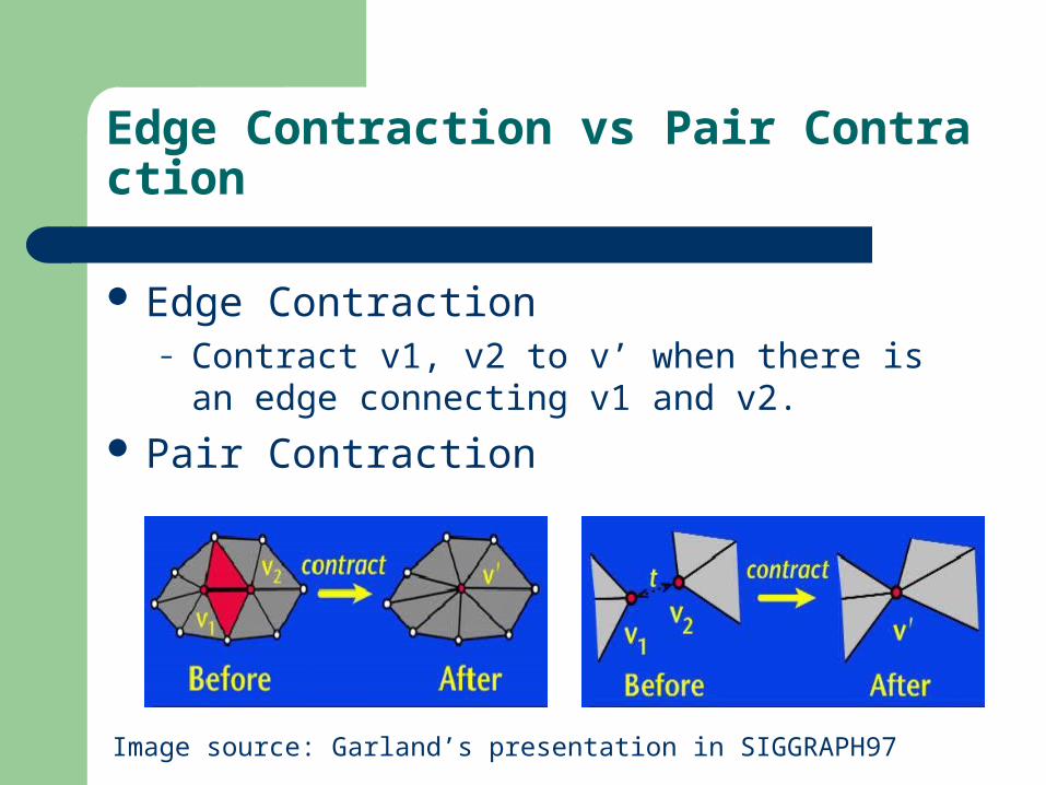
Edge Contraction– Contract v1, v2 to v’ when there is an edge
connecting v1 and v2.
Pair Contraction
Image source: Garland’s presentation in SIGGRAPH97
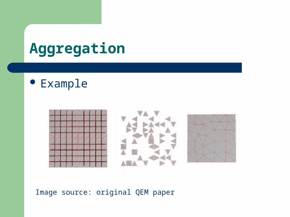
Aggregation
Example
Image source: original QEM paper
Pair Selection
Considering contracting every possible pair is not applicable.
Select a pair v1,v2– (v1, v2) is an edge– ||v1 – v2|| < t, t is a threshold
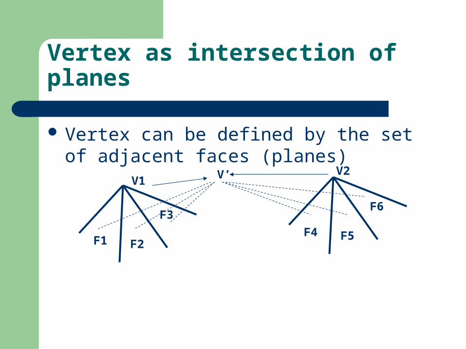
Vertex as intersection of planes
Vertex can be defined by the set of adjacent faces (planes)
V1
F1 F2
F3
F4 F5
F6
V2V’

Cost of Pair Contraction
The cost of contracting a pair (v1,v2) to v’ is the error of replacing v1 and v2 by the new created vertex v’.
For a given point, the error is the sum of square distance to the associated set of planes.
The cost of the contraction is the sum of square distance to the union of two sets of faces adjacent to v1 and v2. (F1, F2, F3, F4, F5, F6)
Quadric Error Metrics
In order to calculate the cost contraction, each vertex must keep track of a set of planes.
After the contraction, the newly created vertex should keep track of the union of two sets of planes associated with the previous two vertices.
Explicitly storing these planes takes more storage.
Quadric Error Metrics
We need the set of planes to calculate the cost of contraction, which is the sum of square distances to the set of planes.
As long as the sum of square distance to the set of planes can be calculated, we do not need to store a set of plane equations.
The set of plane equations associated with each vertex can be replaced by a 4x4 symmetric matrix Q.
Quadric Error Metrics
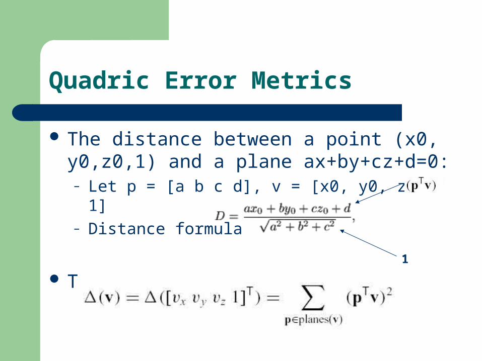
The distance between a point (x0,y0,z0,1) and a plane ax+by+cz+d=0:– Let p = [a b c d], v = [x0, y0, z0, 1]– Distance formula
The sum of square distances: 1

Quadric Error Metrics
Sum of Square DistancesThe quadric matrix
Sum of all quadric matrices
Quadric Error Metrics
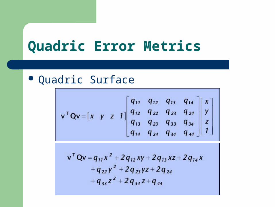
Quadric Surface
Quadric Surface
When the sum of square distances is fixed, the equation is an equation of quadric surface: (ellipsoid, hyperboloid, etc)
The ellipsoid is centered at the vertex. Every point on the ellipsoid surface has the
same error. The ellipsoid captures the local shape of the
surface.
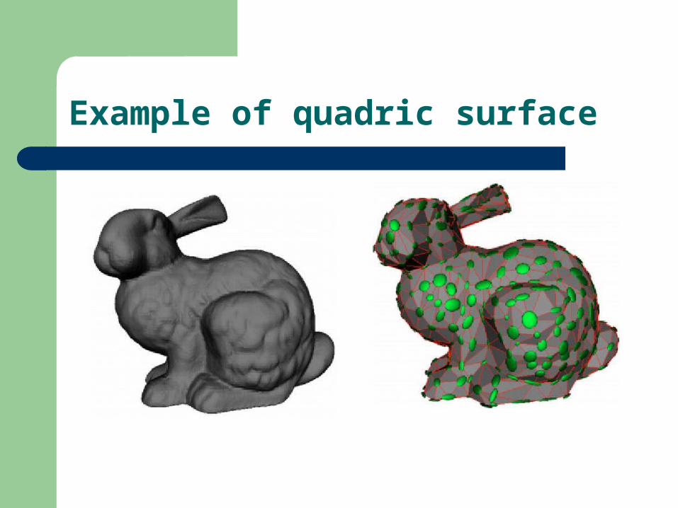
Example of quadric surface
Optimal position for the new vertex
Now we know how to evaluate the cost of contraction, so to determine the cost of contraction, we need to figure out the position of the new vertex after contraction.
Solution: find the vertex location that minimize the cost of the contraction.
Optimal position for the new vertex
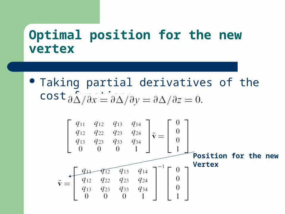
Taking partial derivatives of the cost function:
Position for the newVertex
Optimal position for the new vertex
If the matrix is not invertible, find the optimal vertex on the segment joining the vertex pair, or choosing among the two vertices and the midpoint of the two vertices.
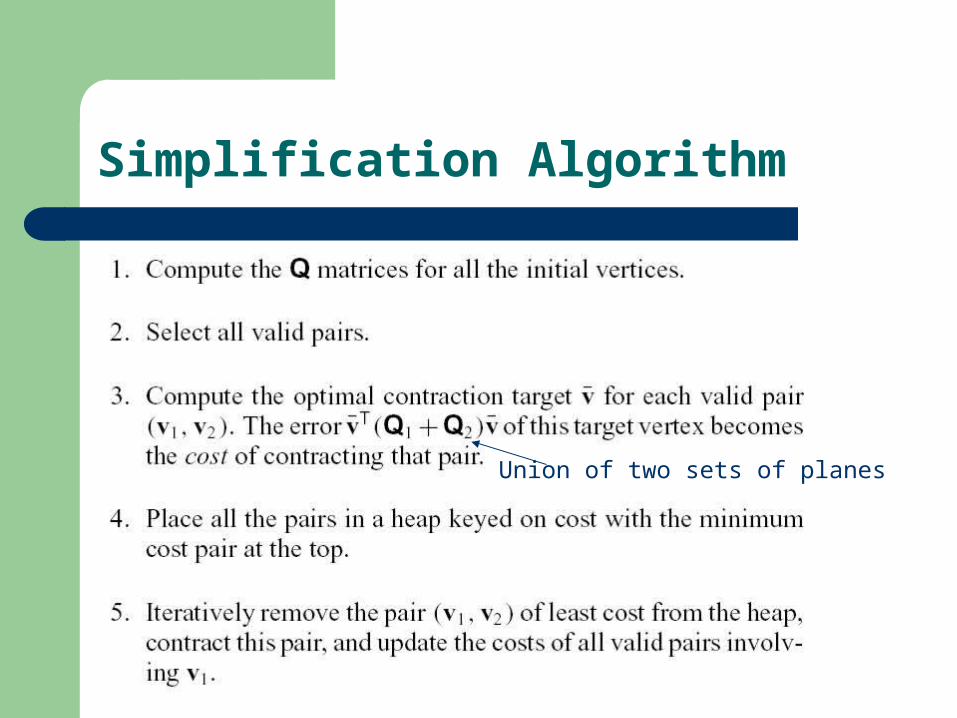
Simplification Algorithm
Union of two sets of planes
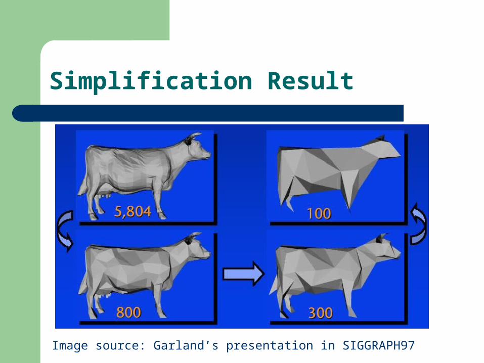
Simplification Result
Image source: Garland’s presentation in SIGGRAPH97
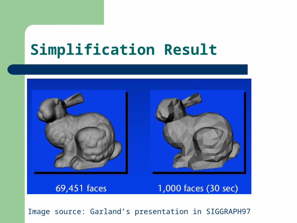
Simplification Result
Image source: Garland’s presentation in SIGGRAPH97
Conclusion
Fast Algorithm and good approximation Compact storage General surface handling
Reference
K. Weiler. The Radial Edge data structure: A topological representation for non-manifold geometric boundary modeling. In J. L. Encarnacao, M. J. Wozny, H. W. McLaughlin, editors, Geometric Modeling for CAD Applications, pages 3--36. Elsevier Science Publishers B. V. (North--Holland), Amsterdam, 1988.
M. Garland and P. Heckbert, "Simplification using quadric error metrics," Proc. Siggraph 1997
Michael Garland and Paul S. Heckbert ,Simplifying Surfaces with Color and Texture using Quadric Error Metrics, IEEE Visualization 98