Embed Size (px)
Citation preview
Thin Solid Films 518 (2010) 3033–3036
Contents lists available at ScienceDirect
Thin Solid Films
j ourna l homepage: www.e lsev ie r.com/ locate / ts f
Surface-oxidized tungsten for energy-storable dye-sensitized solar cells
Yosuke Saito, Satoshi Uchida, Takaya Kubo, Hiroshi Segawa ⁎Research Center for Advanced Science and Technology, The University of Tokyo, 4-6-1, Komaba, Meguro-ku, Tokyo, 153-8904, Japan
⁎ Corresponding author. Tel.: +81 3 5452 5295; fax:E-mail address: [email protected] (H.
0040-6090/$ – see front matter © 2009 Elsevier B.V. Aldoi:10.1016/j.tsf.2009.09.191
a b s t r a c t
a r t i c l e i n f oAvailable online 24 October 2009
Keywords:Nanocrystalline tungsten oxideSurface-oxidized tungstenXRDGITTDye-sensitized solar cell
Tungsten oxide electrodes were investigated as charge-storage materials for energy-storable dye-sensitizedsolar cells (ES-DSSCs). The electrochemical and structural properties of the surface-oxidized tungsten (so-WO3− x) and monoclinic nanocrystalline WO3 (nc-WO3) were studied on the difference of the charge–discharge properties. Although, the electromotive force (EMF) curve of the so-WO3− x was associated withstructural change, the so-WO3− x did not show the significant structural change indicated by X-raydiffraction (XRD) patterns. On the other hand, the nc-WO3 showed crystal transformation from monoclinicphase to tetragonal phase. The Li+ diffusion coefficients of the so-WO3− x with different Li+ content ratiosobtained by the galvanostatic intermittent titration technique (GITT) did not fall down up to 0.3 of Li/Wratio, whereas the diffusion coefficients of nc-WO3 decreased about two orders of magnitude in the vicinityof phase transitions. The different electrochemical properties could be explained by the less structuralchange of so-WO3− x compared with the nc-WO3. The large-sized ES-DSSCs with the so-WO3− x werefabricated for the first time, and their photocharge–discharge performances were studied.
+81 3 5452 5299.Segawa).
l rights reserved.
© 2009 Elsevier B.V. All rights reserved.
1. Introduction
Dye-sensitizedsolarcells(DSSCs)arepromisingtoachievecost-effectivesolarcells, and have been widely studied in recent years [1,2]. One of the basicdrawbacksofconventionalsolarcells is,however, thefluctuationofoutputpowerdepending on climatic conditions. As a solution to this problem, we have addedan energy storage function to the solar cell, namely the “energy-storable dye-sensitized solar cell” (ES-DSSC) [3,4]. The ES-DSSC is a three-electrode systemcomposed of the photo-anode, counter electrode and charge-storage electrode(Fig. 1). In ES-DSSCs, the output power fluctuation is suppressed by dischargingthe stored electricity.
The operation scheme is shown in Fig. 1. When the sunlight falls onthe cell, the dye absorbs incident solar energy, and then injects anelectron to the TiO2 conduction band to form the oxidized dye. Theelectron loses its energy as itworks in theexternal circuit. The electron isthen fed to the counter electrode. The oxidized dye is reduced by I−,which gives rise to I3−, and finally I3− is reduced by the electron at thecounter electrode. The moderate portion of the generated electrons atthe photo-anode are used in the electrochemical reduction of thecharge-storage electrode, and theholes are stored as I3− in theelectrolytesolution. ES-DSSCs repeat this chain of reaction not only to generateelectricity, but also to store electricity as well.
The selection of charge-storagematerials is very important to improvethe performance of ES-DSSCs. Themaximum discharge voltage of the ES-DSSCs is the potential difference between the I3−/I− redox potential andthe redox potential of the charge-storage electrode. The maximum
potential at a charged state is limitedby thebottomof theTiO2 conductionband. Thus, the redox potential in the charge-storage electrode should beslightly downward from the bottom of the TiO2 conduction band. Withthis in mind, we focused on tungsten oxides as the charge-storagematerial of ES-DSSCs [4]. Tungsten oxides have been extensively studieddue to their unique optical and electrical responses caused by thereversible insertion/extraction of H+ and alkali metal ions [5], and aresuitable for charge-storage materials of ES-DSSCs because their conduc-tion band edge is slightly lower than the bottom of the TiO2 conductionband. Recently, we reported the charge–discharge properties of mono-clinic nanocrystalline tungsten oxide (nc-WO3) and surface-oxidizedtungsten (so-WO3−x) [4]. The discharge voltage of the nc-WO3 electrodesignificantly dropped compared with the charge voltage because of itslarge polarization. In contrast, the so-WO3−x electrode showed a smallerpolarization.However, the resultsdidnotgive aclear reasonwhy the layerhad a different property from other structures of tungsten oxides.
In this study, to clarify the difference in electrochemical propertiessuch as polarization potentials, electrochemical and ex-situXRDmeasure-ments were carried out on the so-WO3−x and the nc-WO3, wherein thestructural changes of tungsten oxide layers depending on the Li+
intercalation are found to be the main reason. Additionally, the large-sized ES-DSSCswith the so-WO3−xwere fabricated for the first time, andtheir charge-storage properties were studied.
2. Experimental methods
2.1. Preparations of the tungsten oxide electrodes
The nc-WO3 electrodes were prepared by a screen printingmethod. The WO3 nanoparticle paste was prepared by mixing the
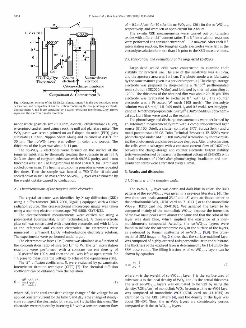
Fig. 1. Operation scheme of the ES-DSSCs. Compartment A is the dye-sensitized solarcell section, and compartment B is the section containing the charge-storage electrode.Compartment A and B are separated by a cation-exchange membrane. Gray arrowsrepresent the electron transfer direction.
3034 Y. Saito et al. / Thin Solid Films 518 (2010) 3033–3036
nanoparticle (particle size<100 nm, Aldrich), ethylcellulose (10 cP),α-terpineol and ethanol using a rocking mill and planetary mixer. TheWO3 paste was screen-printed on an F-doped tin-oxide (FTO) glasssubstrate (10 Ω/sq, Nippon Sheet Glass) and calcined at 450 °C for30 min. The nc-WO3 layer was yellow in color and porous. Thethickness of the layer was about 6–11 µm.
The so-WO3− x electrodes were formed on the surface of thetungsten substrates by thermally treating the substrate in air [6]. A2×3 cm sheet of tungsten substrate with 99.95% purity, and 1 mmthickness was used. The tungsten was heated at 400 °C for 10 min andcooled down in air. The heating and cooling procedures were repeatedfive times. Then the sample was heated at 750 °C for 10 min andcooled down in air. The mass of the so-WO3− x layer was estimated bythe weight uptake caused by oxidization.
2.2. Characterizations of the tungsten oxide electrodes
The crystal structure was identified by X-ray diffraction (XRD)using a diffractometer (RINT-2000, Rigaku) equipped with a CuKαradiation source. The cross-sectional microscope image was takenusing a scanning electron microscope (VE-9800, KEYENCE).
The electrochemical measurements were carried out using apotentiostat (Compactstat, Ivium Technologies). A three-electrodeglass cell was constructed with a working electrode, and with Li foilsas the reference and counter electrodes. The electrodes wereimmersed in a 1 mol/L LiClO4 γ-butyrolactone electrolyte solution.The experiments were performed under argon.
The electromotive force (EMF) curve was obtained as a function ofthe concentration ratio of inserted Li+ to W. The Li+ intercalationreactions were performed with a constant current density of−20 μA/cm2 for 100 s, and then the cell was left at open-circuit for1 h prior to measuring the voltage to achieve the equilibrium state.
The Li+ diffusion coefficients, D, were evaluated by galvanostaticintermittent titration technique (GITT) [7]. The chemical diffusioncoefficient can be obtained from the equation
D̃ =4l2
πτΔEsΔEt
� �2ð1Þ
where ΔEt is the total transient voltage change of the voltage for anapplied constant current for the time τ, andΔEs is the change of steady-state voltage of the electrodes for a step, and l is the film thickness. Theelectrodes were reduced by inserting Li+ with a constant current flow
of−0.2 mA/cm2 for 30 s for the nc-WO3 and 120 s for the so-WO3− x,respectively, and were left at open-circuit for 2 hours.
The ex-situ XRD measurements were carried out on tungstenoxideswith different Li+ content ratios. The Li+ intercalation reactionswere performed at a constant current of−0.2 mA/cm2. After each Li+
intercalation reaction, the tungsten oxide electrodes were left in theelectrolyte solution for more than 2 h prior to the XRDmeasurements.
2.3. Fabrications and evaluations of the large-sized ES-DSSCs
Large-sized sealed cells were constructed to examine theirviability for practical use. The size of the substrates was 4×5 cm,and the aperture area was 3×3 cm. The photo-anode was fabricatedby the samemanner given in a previous report [4]. The charge-storageelectrode was prepared by drop-coating a Nafion® perfluorinatedresin solution (DE2020, Wako) and followed by thermal annealing at120 °C. The thickness of the obtained film was about 20–30 μm. Thiselectrode was pretreated to exchange H+ with Li+. The counterelectrode was a Pt-coated W mesh (105 mesh). The electrolytesolution was 0.5 mol/L LiI, 0.05 mol/L I2 and 0.5 mol/L tert-butylpyr-idine in 3-methoxypropionitrile. Surlyn® (DuPont-Mitsui polychemi-cal co., Ltd.) films were used as the sealant.
The photocharge and discharge measurements were performed byan automated measurement system with a computer-controlled lightsource (91160, Oriel), a shutter controller (F77, Suruga Seiki) and amulti-potentiostat (PS-08, Toho Technical Research). ES-DSSCs werephotocharged under AM 1.5 100 mW/cm2 irradiation by short-circuit-ing the photo-anode and charge-storage electrode. After photocharging,the cells were discharged with a constant current flow of 0.027 mAbetween the charge-storage and counter electrode. Output stabilitytestswere performedbymeasuring the output voltage of ES-DSSCswitha load resistance of 10 kΩ after photocharging. Irradiation and non-irradiation states were alternated every 10 min.
3. Results and discussion
3.1. Structures of the tungsten oxides
The so-WO3− x layer was dense and dark blue in color. The XRDpattern of the so-WO3− x was given in a previous literature. [4]. Thetwo dominant peaks around 23.4° and 48° were attributed either tothe orthorhombic WO3 (ICDD card no. 71-0131) or to the monoclinicWO2.90 (ICDD card no. 36-0102). We assigned the layer to becomposed mainly of the monoclinic WO2.90 because the intensitiesof the two main peaks were almost the same and that the color of thelayer was dark blue, which implied the existence of a non-stoichiometric compound. Actually, the so-WO3−x layers werefound to include the orthorhombic WO3 in the surface of the layers,as evidenced by Raman scattering of so-WO3−x [8,9]. The cross-sectional SEM image in Fig. 2 shows that the surface-oxidized layerwas composed of highly-ordered rods perpendicular to the substrate.The thickness of the oxidized layer is determined to be 11.4 µm by theSEM observation. The filling fraction, ρ, of so-WO3− x layers can beshown by equation
ρ =mdS
⋅1l
ð2Þ
where m is the weight of so-WO3−x layer, S is the surface area ofsubstrate, d is the ideal density of WO3, and l is the actual thickness.The ρ of so-WO3−x layers was estimated to be 92% by using thedensity, 7.28 g/cm3, of monoclinic WO3. In contrast, the nc-WO3 layerwas composed of monoclinic WO3 (ICDD card no. 43-1035) asidentified by the XRD pattern [4], and the density of the layer wasabout 30–40%. Thus, the nc-WO3 layers are considerably porouscompared with the so-WO3− x layers.
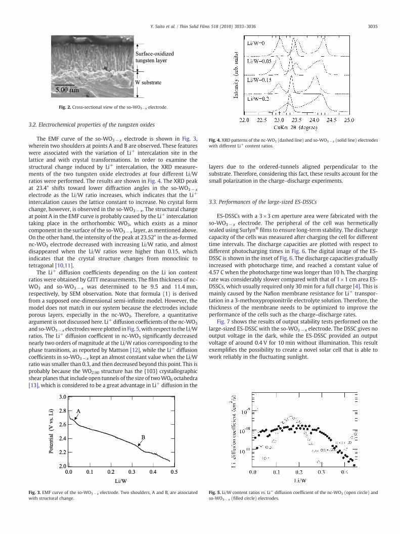
Fig. 2. Cross-sectional view of the so-WO3−x electrode.
Fig. 4. XRD patterns of the nc-WO3 (dashed line) and so-WO3− x (solid line) electrodeswith different Li+ content ratios.
3035Y. Saito et al. / Thin Solid Films 518 (2010) 3033–3036
3.2. Electrochemical properties of the tungsten oxides
The EMF curve of the so-WO3− x electrode is shown in Fig. 3,wherein two shoulders at points A and B are observed. These featureswere associated with the variation of Li+ intercalation site in thelattice and with crystal transformations. In order to examine thestructural change induced by Li+ intercalation, the XRD measure-ments of the two tungsten oxide electrodes at four different Li/Wratios were performed. The results are shown in Fig. 4. The XRD peakat 23.4° shifts toward lower diffraction angles in the so-WO3− x
electrode as the Li/W ratio increases, which indicates that the Li+
intercalation causes the lattice constant to increase. No crystal formchange, however, is observed in the so-WO3− x. The structural changeat point A in the EMF curve is probably caused by the Li+ intercalationtaking place in the orthorhombic WO3, which exists as a minorcomponent in the surface of the so-WO3− x layer, as mentioned above.On the other hand, the intensity of the peak at 23.52° in the as-formednc-WO3 electrode decreased with increasing Li/W ratio, and almostdisappeared when the Li/W ratios were higher than 0.15, whichindicates that the crystal structure changes from monoclinic totetragonal [10,11].
The Li+ diffusion coefficients depending on the Li ion contentratios were obtained by GITT measurements. The film thickness of nc-WO3 and so-WO3− x was determined to be 9.5 and 11.4 mm,respectively, by SEM observation. Note that formula (1) is derivedfrom a supposed one-dimensional semi-infinite model. However, themodel does not match in our system because the electrodes includeporous layers, especially in the nc-WO3. Therefore, a quantitativeargument is not discussed here. Li+ diffusion coefficients of the nc-WO3
and so-WO3−x electrodeswereplotted inFig. 5,with respect to the Li/Wratios. The Li+ diffusion coefficient in nc-WO3 significantly decreasednearly two orders of magnitude at the Li/W ratios corresponding to thephase transitions, as reported by Mattson [12], while the Li+ diffusioncoefficients in so-WO3−x kept an almost constant value when the Li/Wratio was smaller than 0.3, and then decreased beyond this point. This isprobably because the WO2.90 structure has the {103} crystallographicshear planes that include open tunnels of the size of twoWO6 octahedra[13], which is considered to be a great advantage in Li+ diffusion in the
Fig. 3. EMF curve of the so-WO3− x electrode. Two shoulders, A and B, are associatedwith structural change.
layers due to the ordered-tunnels aligned perpendicular to thesubstrate. Therefore, considering this fact, these results account for thesmall polarization in the charge–discharge experiments.
3.3. Performances of the large-sized ES-DSSCs
ES-DSSCs with a 3×3 cm aperture area were fabricated with theso-WO3− x electrode. The peripheral of the cell was hermeticallysealed using Surlyn®
films to ensure long-term stability. The dischargecapacity of the cells was measured after charging the cell for differenttime intervals. The discharge capacities are plotted with respect todifferent photocharging times in Fig. 6. The digital image of the ES-DSSC is shown in the inset of Fig. 6. The discharge capacities graduallyincreased with photocharge time, and reached a constant value of4.57 C when the photocharge time was longer than 10 h. The chargingrate was considerably slower compared with that of 1×1 cm area ES-DSSCs, which usually required only 30 min for a full charge [4]. This ismainly caused by the Nafion membrane resistance for Li+ transpor-tation in a 3-methoxypropionitrile electrolyte solution. Therefore, thethickness of the membrane needs to be optimized to improve theperformance of the cells such as the charge–discharge rates.
Fig. 7 shows the results of output stability tests performed on thelarge-sized ES-DSSC with the so-WO3− x electrode. The DSSC gives nooutput voltage in the dark, while the ES-DSSC provided an outputvoltage of around 0.4 V for 10 min without illumination. This resultexemplifies the possibility to create a novel solar cell that is able towork reliably in the fluctuating sunlight.
Fig. 5. Li/W content ratios vs. Li+ diffusion coefficient of the nc-WO3 (open circle) andso-WO3− x (filled circle) electrodes.
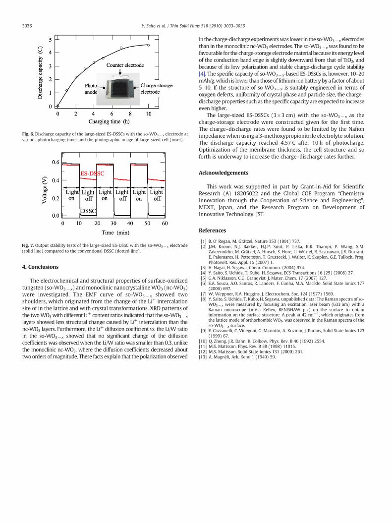
Fig. 6. Discharge capacity of the large-sized ES-DSSCs with the so-WO3− x electrode atvarious photocharging times and the photographic image of large-sized cell (inset).
Fig. 7. Output stability tests of the large-sized ES-DSSC with the so-WO3− x electrode(solid line) compared to the conventional DSSC (dotted line).
3036 Y. Saito et al. / Thin Solid Films 518 (2010) 3033–3036
4. Conclusions
The electrochemical and structural properties of surface-oxidizedtungsten (so-WO3− x) andmonoclinic nanocrystallineWO3 (nc-WO3)were investigated. The EMF curve of so-WO3− x showed twoshoulders, which originated from the change of the Li+ intercalationsite of in the lattice and with crystal transformations. XRD patterns ofthe twoWO3with different Li+ content ratios indicated that the so-WO3−x
layers showed less structural change caused by Li+ intercalation than thenc-WO3 layers. Furthermore, the Li+ diffusion coefficient vs. the Li/W ratioin the so-WO3−x showed that no significant change of the diffusioncoefficients was observedwhen the Li/W ratio was smaller than 0.3, unlikethe monoclinic nc-WO3, where the diffusion coefficients decreased abouttwo orders ofmagnitude. These facts explain that the polarization observed
in thecharge-dischargeexperimentswas lower in theso-WO3−xelectrodesthan in themonoclinic nc-WO3 electrodes. The so-WO3−xwas found to befavourable for thecharge-storageelectrodematerial because itsenergy levelof the conduction band edge is slightly downward from that of TiO2, andbecause of its low polarization and stable charge-discharge cycle stability[4]. The specific capacity of so-WO3−x-based ES-DSSCs is, however, 10–20mAh/g,which is lower than thoseof lithium ionbattery by a factor of about5–10. If the structure of so-WO3−x is suitably engineered in terms ofoxygen defects, uniformity of crystal phase and particle size, the charge–discharge properties such as the specific capacity are expected to increaseeven higher.
The large-sized ES-DSSCs (3×3 cm) with the so-WO3− x as thecharge-storage electrode were constructed given for the first time.The charge–discharge rates were found to be limited by the Nafionimpedance when using a 3-methoxypropionitrile electrolyte solution.The discharge capacity reached 4.57 C after 10 h of photocharge.Optimization of the membrane thickness, the cell structure and soforth is underway to increase the charge–discharge rates further.
Acknowledgements
This work was supported in part by Grant-in-Aid for ScientificResearch (A) 18205022 and the Global COE Program “ChemistryInnovation through the Cooperation of Science and Engineering”,MEXT, Japan, and the Research Program on Development ofInnovative Technology, JST.
References
[1] B. O' Regan, M. Grätzel, Nature 353 (1991) 737.[2] J.M. Kroon, N.J. Bakker, H.J.P. Smit, P. Liska, K.R. Thampi, P. Wang, S.M.
Zakeeruddin, M. Grätzel, A. Hinsch, S. Hore, U. Würfel, R. Sastrawan, J.R. Durrant,E. Palomares, H. Pettersson, T. Gruszecki, J. Walter, K. Skupien, G.E. Tulloch, Prog.Photovolt. Res. Appl. 15 (2007) 1.
[3] H. Nagai, H. Segawa, Chem. Commun. (2004) 974.[4] Y. Saito, S. Uchida, T. Kubo, H. Segawa, ECS Transactions 16 (25) (2008) 27.[5] G.A. Niklasson, C.G. Granqvist, J. Mater. Chem. 17 (2007) 127.[6] E.A. Souza, A.O. Santos, R. Landers, F. Cunha, M.A. Macêdo, Solid State Ionics 177
(2006) 697.[7] W. Weppner, R.A. Huggins, J. Electrochem. Soc. 124 (1977) 1569.[8] Y. Saito, S. Uchida, T. Kubo, H. Segawa, unpublished data: The Raman spectra of so-
WO3− x were measured by focusing an excitation laser beam (633 nm) with aRaman microscope (inVia Reflex, RENISHAW plc) on the surface to obtaininformation on the surface structure. A peak at 42 cm−1, which originates fromthe lattice mode of orthorhombic WO3, was observed in the Raman spectra of theso-WO3− x surface.
[9] E. Cazzanelli, C. Vinegoni, G. Mariotto, A. Kuzmin, J. Purans, Solid State Ionics 123(1999) 67.
[10] Q. Zhong, J.R. Dahn, K. Colbow, Phys. Rev. B 46 (1992) 2554.[11] M.S. Mattsson, Phys. Rev. B 58 (1998) 11015.[12] M.S. Mattsson, Solid State Ionics 131 (2000) 261.[13] A. Magnéli, Ark. Kemi 1 (1949) 59.