Embed Size (px)
Citation preview

Surface-mountingThermostats
Series ATH
B 60.3021.0Operating Instructions
05.03/00073784
ATHs-1
ATHf-70/g

H Please read these Operating Instructions before commissioning the instrument. Keep themanual in a place which is accessible to all users at all times. Please assist us to improvethese operating instructions where necessary. Your suggestions will be welcome.
Phone in Germany 0661 6003-716abroad +49 661 6003-0
Fax in Germany 0661 6003-504abroad +49 661 6003-607
H All necessary settings and possible adjustments inside the instrument are described inthese operating instructions. However, if any problems should still arise during commis-sioning, you are asked not to carry out any unauthorized manipulations on the unit. Youcould endanger your rights under the instrument warranty! Please contact the nearestsubsidiary or the main factory.

Contents Page
1 Introduction ............................................................................... 3
1.1 Typographical conventions ...................................................................... 31.1.1 Warnings ..................................................................................................... 31.1.2 Note signs ................................................................................................... 3
1.2 Application ................................................................................................. 4
1.3 Conformity ................................................................................................. 4
1.4 Safety notes ............................................................................................... 4
2 Instrument identification .......................................................... 5
2.1 Nameplate .................................................................................................. 5
2.2 Type designation ....................................................................................... 5
3 Mounting .................................................................................... 6
3.1 Dimensions ................................................................................................ 6
3.2 Opening the case ...................................................................................... 9
3.3 Securing the surface-mounting thermostat ........................................... 93.3.1 Code s (rigid stem) ...................................................................................... 93.3.2 Code f (with capillary) .................................................................................. 9
3.4 Capillary / Temperature probe / Pocket ................................................ 103.4.1 General ...................................................................................................... 103.4.2 Approved probes and pockets ................................................................. 11
3.5 Permissible pressure loading on pocket .............................................. 143.5.1 Pockets U, US, UZ, UZS, E, ES and EZS ................................................. 14
3.6 Mounting the probe ................................................................................. 18
4 Installation ............................................................................... 19
4.1 Regulations and notes ............................................................................ 19
4.2 Electrical connection .............................................................................. 204.2.1 Closing the case ....................................................................................... 21
Contents Page
5 Settings .................................................................................... 23
5.1 Setpoint /limit setting ............................................................................. 235.1.1 Controller TR ............................................................................................. 235.1.2 Monitor and limiter TW, STW (STB), TB, STB ........................................... 23
5.2 Limiting the setpoint range .................................................................... 24
5.3 Resetting the TB and STB ...................................................................... 25
5.4 Self-monitoring ........................................................................................ 265.4.1 Response to a fracture of the measuring system ..................................... 265.4.2 Response to falling below the temperature limit ....................................... 26
5.5 Use of the STW (STB) as STB ................................................................. 26
6 Instrument description ........................................................... 27
6.1 Technical data ......................................................................................... 27
3
1 Introduction
1.1 Typographical conventions
1.1.1 Warnings
1.1.2 Note signs
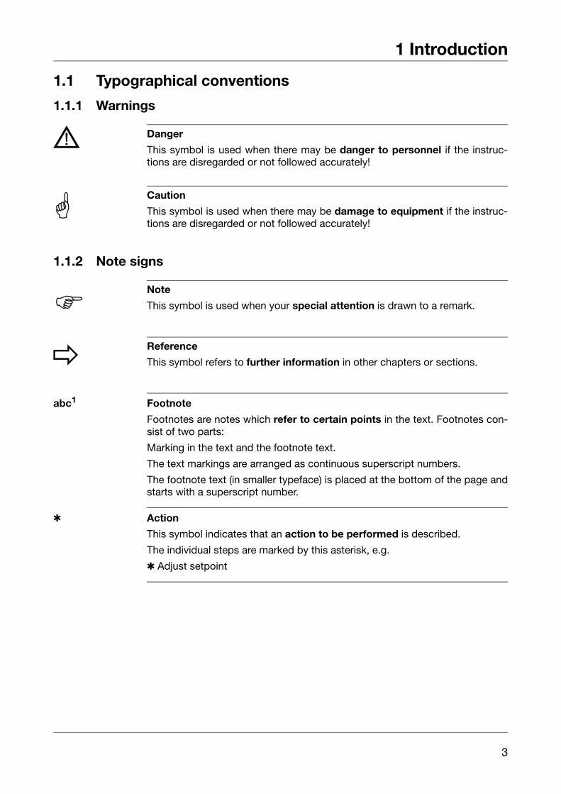
abc1 Footnote
Footnotes are notes which refer to certain points in the text. Footnotes con-sist of two parts:
Marking in the text and the footnote text.
The text markings are arranged as continuous superscript numbers.
The footnote text (in smaller typeface) is placed at the bottom of the page andstarts with a superscript number.
Action
This symbol indicates that an action to be performed is described.
The individual steps are marked by this asterisk, e.g.
Adjust setpoint
V Danger
This symbol is used when there may be danger to personnel if the instruc-tions are disregarded or not followed accurately!
A Caution
This symbol is used when there may be damage to equipment if the instruc-tions are disregarded or not followed accurately!
H Note
This symbol is used when your special attention is drawn to a remark.
v Reference
This symbol refers to further information in other chapters or sections.

1 Introduction
4
1.2 Application
Surface-mounting thermostats Series ATH are approved as:
Temperature controller (TR)
Temperature monitor (TW)
Temperature limiter (TB)
Safety temperature limiter (STB)
Safety temperature monitor STW (STB)
Type examination to:- DIN 3440- Pressure Equipment Directive 97/23/EC
1.3 Conformity
1.4 Safety notesPhysical and toxicological properties of the media which may escape in theevent of a system fracture:
A Cutting through or kinking the capillary will lead to permanent instrument failure !
H Surface-mounting thermostats Series ATH conform to VDE 0631.
Range withtop end of scale
Danger-ous
reaction
Fire / explosionhazard
Watercontami-
nation
Toxicological data
Ignitiontemp.
°C
Explosionlimit
% v/v
irritant dangerto
health
toxic
liquid-filled
≥ +200°C < +200°C no +280°C 1.2 — 7.5 yes yes 1) no≥ +200°C ≤ +350°C no +490°C 1.0 — 3.5 yes yes 1) no
gas-filled≥ +400°C ≤ +500°C no
H 1) The filling liquid may escape in the event of a measuring system fracture. Atpresent there is no restrictive statement from the health authorities concerningany danger to health over short periods and at low concentrations, e.g. after afracture of the measuring system.
5
2 Instrument identification
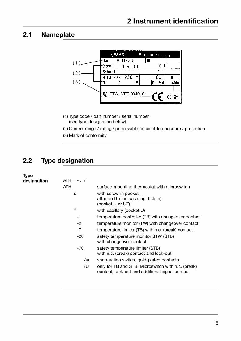
2.1 Nameplate
(1) Type code / part number / serial number(see type designation below)
(2) Control range / rating / permissible ambient temperature / protection
(3) Mark of conformity
2.2 Type designation
Typedesignation
( 1 )
( 2 )
( 3 )
ATH . - . ./
ATH surface-mounting thermostat with microswitch
s with screw-in pocketattached to the case (rigid stem)(pocket U or UZ)
f with capillary (pocket U)-10 temperature controller (TR) with changeover contact
-20 temperature monitor (TW) with changeover contact
-70 temperature limiter (TB) with n.c. (break) contact-20 safety temperature monitor STW (STB)
with changeover contact
-70 safety temperature limiter (STB)with n.c. (break) contact and lock-out
/au snap-action switch, gold-plated contacts
/U only for TB and STB. Microswitch with n.c. (break)contact, lock-out and additional signal contact
6
3 Mounting
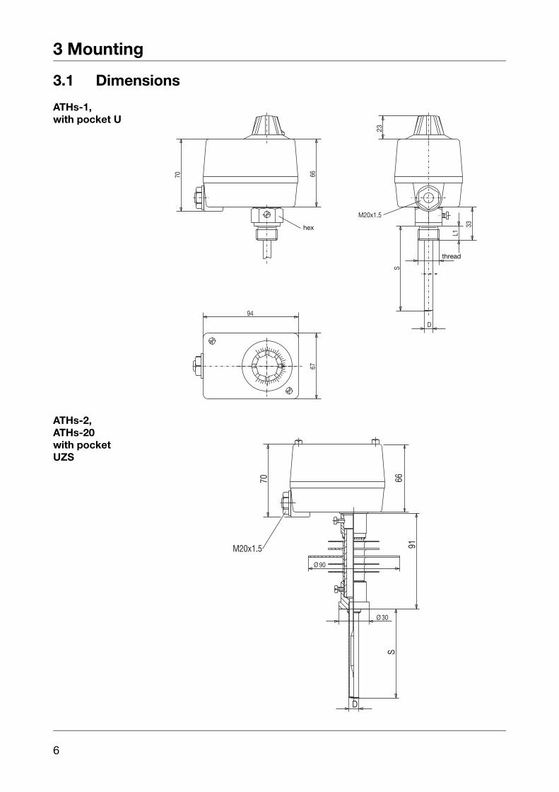
3.1 Dimensions
ATHs-1,with pocket U
ATHs-2,ATHs-20with pocketUZS
SW
M20x1.5
6670
L1
G
D
S
33
23
6794
hex
thread
M20x1.5
6670
S
D
90Ø
91
30Ø

7
3 Mounting
ATHf-2/r,ATHf-20/rwith plaincylindricalprobe A,no pocket
ATHf-1/b,with pocket U
Bohrplan
M20x1.570 45
72
67
94
Ø4.
5
d
L
drilling diagram
SWSW
M20x1.5
70
G
S
L1
G
S
L1
94
23
D
65
Ø 6.5
67
66
hex
thread
3 Mounting
8
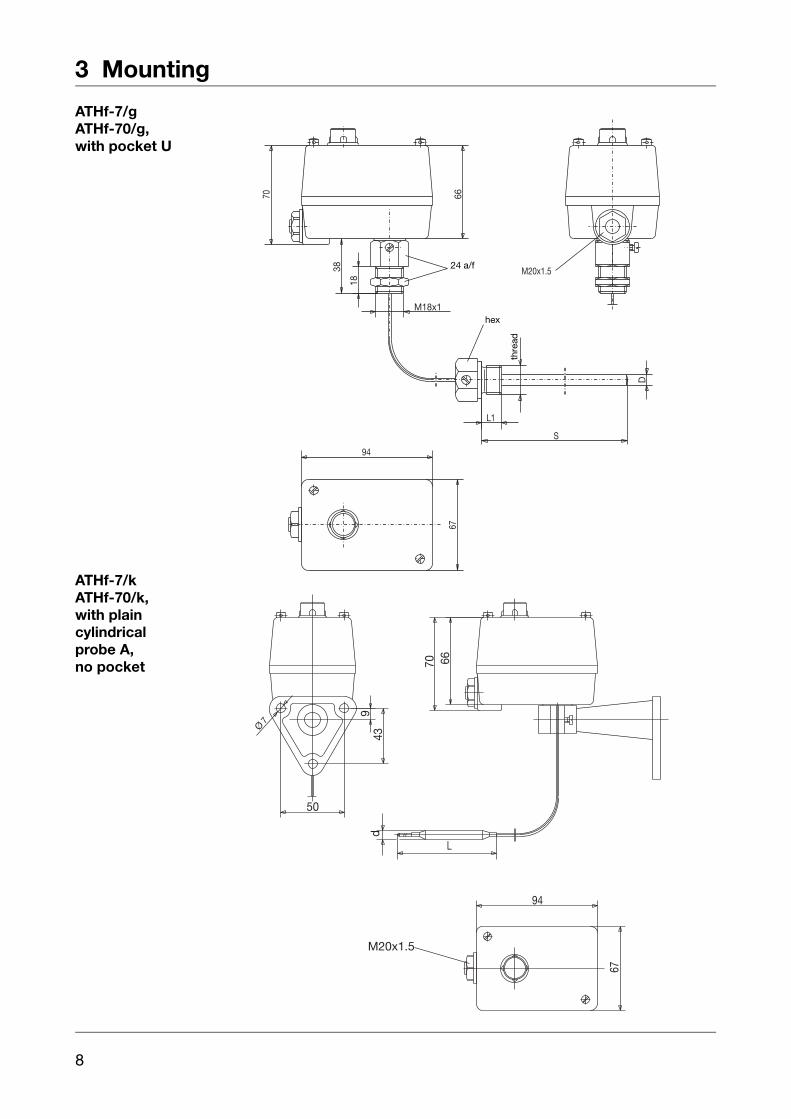
ATHf-7/gATHf-70/g,with pocket U
ATHf-7/kATHf-70/k,with plaincylindrical probe A,no pocket
SW
SW24 M20x1.570
L1
G
S
66
38
18
M18x1
D
6794
thre
ad
hex
24 a/f
M20x1.5
d
L
6670
67
94
439
7Ø
50
9
3 Mounting
3.2 Opening the case
Opening Unscrew the 2 cover screws
Remove case top
3.3 Securing the surface-mounting thermostat
Mountingposition
to DIN 16 257, nom. position NL 0 — 90° (other NL on request)
3.3.1 Code s (rigid stem)
The case spigot is secured by a fixing screw in the enlarged pocket opening.
3.3.2 Code f (with capillary)
Thermostat head fixing
V Make sure the seal is correctly seated when assembling!
Code Descriptiong standard
thread with locknut M 18 x 1 at case spigot, capillary entry at case spigot
r by two screws through base of case, capillary entry at the side of the case
b steel mounting flange, capillary entry at case spigotk wall bracket

3 Mounting
10
3.4 Capillary / Temperature probe / Pocket
3.4.1 General
A Cutting through of kinking the capillary of the surface-mounting thermostat willresult in permanent failure of the instrument!
The minimum permissible bending radius of the capillary is 5 mm.
The temperature probe must be installed in JUMO pockets, otherwise theapproval of the surface-mounting thermostat becomes invalid.
H The temperature probe must be completely immersed in the medium.
To ensure their overall accuracy, the thermostats must only be used in con-junction with the pockets supplied by the factory (diameter D = 8, 10 mm).
Pockets with diameter D = 10 mm may only be fitted with probes withdiameter d = 8 mm.
When used in air, a process connection without pocket must be chosen.

11
3 Mounting
3.4.2 Approved probes and pockets
A U UZPlain cylindrical bulb Screw-in pocket with
screw-in spigot Form A to DIN 38522/2.With fixing screw.
Screw-in pocketwith fixing screw and extension
L
_15
Ød
SW
ØD
G
L1
S
hex
thread
hex
1/2" pipe
US UZS
Weld-in pocketwith fixing screwand clamp
Weld-in pocketwith sealing shoulder; fixing screw andextension
S
27
S
ØD
Ø25
Ø10
Ø13
Ø8
Ø12
Ø30

3 Mounting
12
B C DProbe form Cwith loose nipple,threaded on both ends.
Plain cylindrical bulbwith shoulder and union nut. Shoulder brazed or welded to capillary.
Plain cylindrical bulb, threaded connectorbrazed or welded to capillary.
UH UO UZOScrew-in pocket withfixing screw, no sealing shoulder
Screw-in pocket with screw-in spigot Form A to DIN 3852/2,with fixing screw
For Code sabove +150°C probetemperature, pocket open at end and screw-in spigot Form A to DIN 3852/2, with fixing screw and extension
thread
hex
thread
hex
thread
hex
hex
thread
hex
thread hex
thread
13
3 Mounting
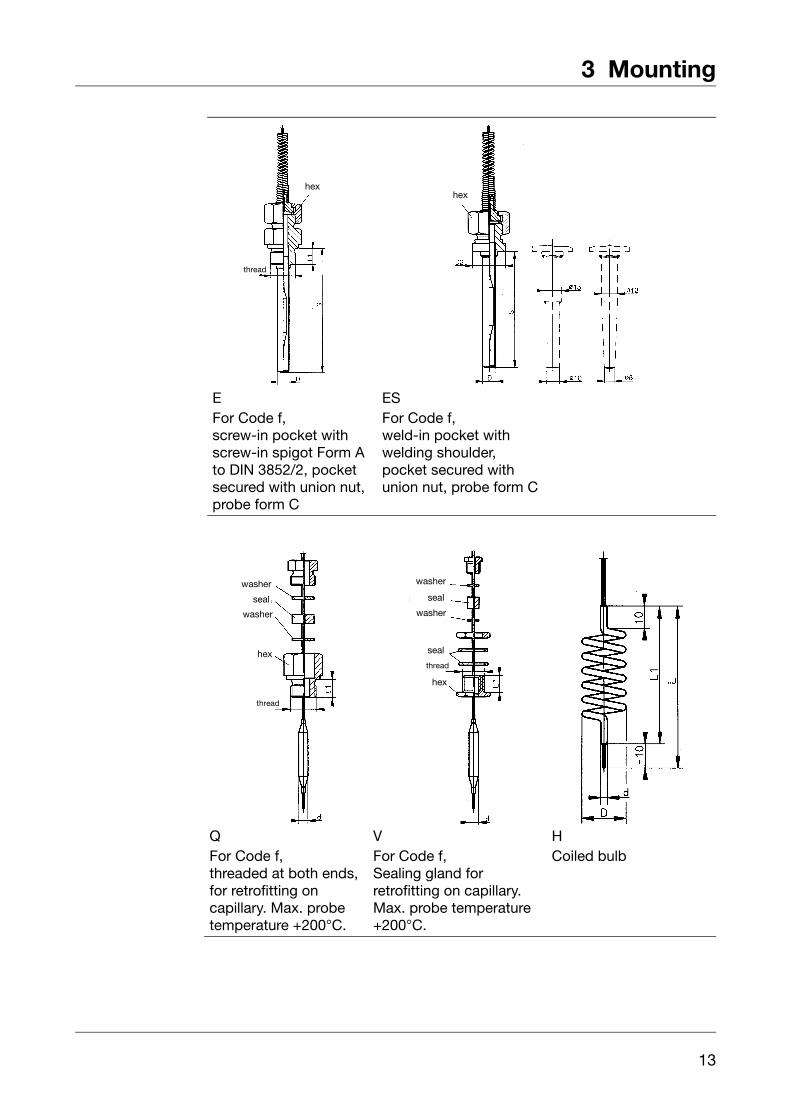
E ESFor Code f,screw-in pocket with screw-in spigot Form A to DIN 3852/2, pocket secured with union nut, probe form C
For Code f,weld-in pocket withwelding shoulder,pocket secured with union nut, probe form C
hex
thread
hex
Q V HFor Code f,threaded at both ends, for retrofitting oncapillary. Max. probe temperature +200°C.
For Code f,Sealing gland forretrofitting on capillary. Max. probe temperature +200°C.
Coiled bulb
washer
seal
washer
hex
thread
washer
seal
washer
seal
hex
thread
3 Mounting
14
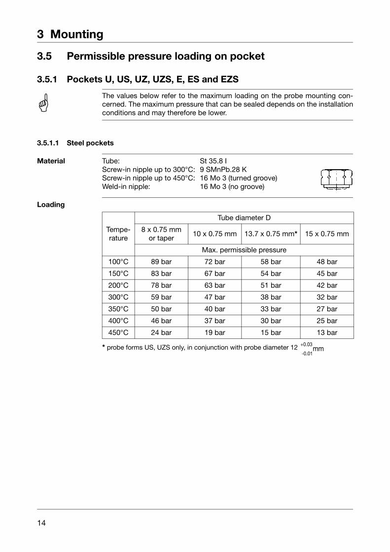
3.5 Permissible pressure loading on pocket
3.5.1 Pockets U, US, UZ, UZS, E, ES and EZS
3.5.1.1 Steel pockets
Material Tube: St 35.8 IScrew-in nipple up to 300°C: 9 SMnPb.28 KScrew-in nipple up to 450°C: 16 Mo 3 (turned groove)Weld-in nipple: 16 Mo 3 (no groove)
Loading
A The values below refer to the maximum loading on the probe mounting con-cerned. The maximum pressure that can be sealed depends on the installationconditions and may therefore be lower.
Tempe-rature
Tube diameter D
8 x 0.75 mmor taper
10 x 0.75 mm 13.7 x 0.75 mm* 15 x 0.75 mm
Max. permissible pressure
100°C 89 bar 72 bar 58 bar 48 bar
150°C 83 bar 67 bar 54 bar 45 bar
200°C 78 bar 63 bar 51 bar 42 bar
300°C 59 bar 47 bar 38 bar 32 bar
350°C 50 bar 40 bar 33 bar 27 bar
400°C 46 bar 37 bar 30 bar 25 bar
450°C 24 bar 19 bar 15 bar 13 bar
* probe forms US, UZS only, in conjunction with probe diameter 12 +0.03mm
-0.01

15
3 Mounting
Permissibleflow velocity
Permissible flow velocity (m/sec) at max. permissible pressure loading and dif-ferent immersion tube lengths S.
Permissible flow velocity (m/sec) at max. permissible pressure loading and dif-ferent immersion tube temperatures t.
Temperature: +200°C
Thermal medium:air ( 1 )water, oil ( 2 )
Tube dia. D: 08 mm10 mm
. . . . . . . . . . . . . . 15 mm
air ( 1 )water, oil ( 2)
Immersion tube length ( mm )
A The values below refer to the maximum loading on the probe mounting con-cerned. The maximum pressure that can be sealed depends on the installationcondition and may therefore be lower.
Temperature: +200°C
Thermal medium:air ( 1 )water, oil ( 2 )
Tube diameter D: 08 mm10 mm
. . . . . . . . . . . . . . 15 mm
air ( 1 )
water, oil ( 2)
Temperature ( °C )

3 Mounting
16
3.5.1.2 Stainless steel pockets
Material
Permissibleflow velocity
on request
3.5.1.3 Brass pockets
Material
Pocket UH
Permissibleflow velocity
on request
Tube and nipple: X 6 CrNiMoTl 17 122
TemperatureTube diameter D
8 x 0.75 mmor taper
10 x 0.75 mm 15 x 0.75 mm
Max. permissible pressure
100°C 92 bar 74 bar 50 bar
150°C 88 bar 71 bar 48 bar
200°C 83 bar 67 bar 45 bar
300°C 72 bar 58 bar 39 bar
400°C 67 bar 54 bar 36 bar
Tube and nipple: brass (CuZn)
Temperature
Tube diameter D
8 x 0.75 mm 10 x 0.75 mm 15 x 0.75 mm
Max. permissible pressure
100°C 50 bar 40 bar 27 bar
150°C 48 bar 39 bar 26 bar
110°C 16 bar

17
3 Mounting
3.5.1.4 Probe mountings B, C, D
(probe in direct contact with medium)
The process connections A, H, UO, UZO, Q and V may only be used in pres-sure-free media.
Nipple material
CuZn 39 9 SMnPb.28K X 6 CrNiMoTi 17 122
Max. temperature
200°C 300°C 400°C
Probe material Ø mm dia.Thermostat function
TR, TW, TB STB, STW (STB)
SF-CuF 29
04 06 bar
2 bar
05 05 bar
06 04 bar
07 03 bar
08 03 bar
09 03 bar
10 03 bar
1.4571 (V4A); St 35 04 — 10 10 bar 2 bar
A To ensure their overall accuracy, the thermostats may only be used togetherwith the pockets supplied by the factory.
Fitting several probes into a common pocket is only permitted with 2 or 3cylindrical probes 6 mm dia. and pockets 15 x 0.75 mm.
When fitting 2 probes into a common pocket, the factory-supplied spring clipmust be fitted inside the pocket.
With pockets U, US, UZ, UZS, E, ES and EZS in materials St 35.8I and16Mo 3, the permissible operating life at operating temperatures above 420°Cis limited to 200,000 hours. Please refer to the requirements of TRD 508 forapplication in this range.
3 Mounting
18
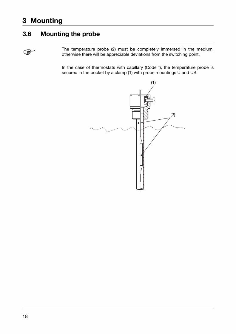
3.6 Mounting the probe
In the case of thermostats with capillary (Code f), the temperature probe issecured in the pocket by a clamp (1) with probe mountings U and US.
H The temperature probe (2) must be completely immersed in the medium,otherwise there will be appreciable deviations from the switching point.
(1)
(2)
19
4 Installation
4.1 Regulations and notes
V The electrical connection must only be carried out by qualified personnel.
The choice of cable, the installation and the electrical connection mustconform to the requirements of VDE 0100 “Regulations on the installation of power circuits with nominal voltages below 1000 V”, or the appropriate local regulations.
Ensure that the instrument is completely isolated from the mains supply before carrying out work where live components may be touched.
Earth the instrument at terminal PE to the protective earth. This cable must have at least the same cross-section as the supply cable. Earthing cables must be wired in star configuration, to a common earthing point which is connected to the protective earth of the supply. Do not loop the earthing cables, i.e. do not run them from one instrument to another.
Apart from faulty installation, incorrect settings on the thermostat may also affect the proper functioning of the following process or lead to damage. Adjustments should therefore only be made by qualified personnel.Please observe the corresponding safety regulations in this matter.
4 Installation
20
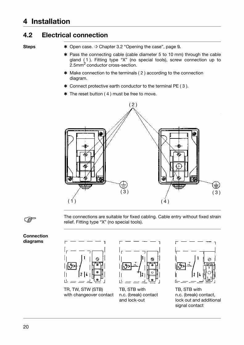
4.2 Electrical connection
Steps Open case. Chapter 3.2 “Opening the case”, page 9.
Pass the connecting cable (cable diameter 5 to 10 mm) through the cablegland ( 1 ). Fitting type “X” (no special tools), screw connection up to2.5mm2 conductor cross-section.
Make connection to the terminals ( 2 ) according to the connectiondiagram.
Connect protective earth conductor to the terminal PE ( 3 ).
The reset button ( 4 ) must be free to move.
Connectiondiagrams
TR, TW, STW (STB) TB, STB with TB, STB withwith changeover contact n.c. (break) contact n.c. (break) contact,
and lock-out lock out and additionalsignal contact
( 1 )
( 2 )
( 3 ) ( 3 )
( 4 )
H The connections are suitable for fixed cabling. Cable entry without fixed strainrelief. Fitting type “X” (no special tools).
21
4 Installation
4.2.1 Closing the case
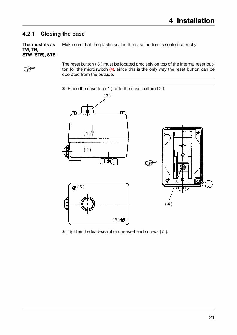
Thermostats as TW, TB, STW (STB), STB
Make sure that the plastic seal in the case bottom is seated correctly.
Place the case top ( 1 ) onto the case bottom ( 2 ).
Tighten the lead-sealable cheese-head screws ( 5 ).
H The reset button ( 3 ) must be located precisely on top of the internal reset but-ton for the microswitch (4), since this is the only way the reset button can beoperated from the outside.
( 3 )
( 1 )
( 2 )
( 5 )
( 5 )
( 4 )
H
4 Installation
22
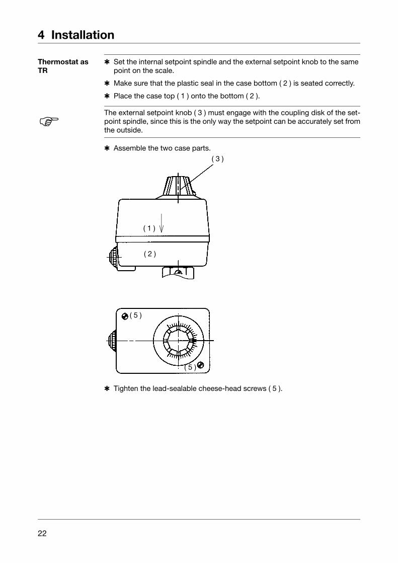
Thermostat as TR
Set the internal setpoint spindle and the external setpoint knob to the same point on the scale.
Make sure that the plastic seal in the case bottom ( 2 ) is seated correctly.
Place the case top ( 1 ) onto the bottom ( 2 ).
Assemble the two case parts.
Tighten the lead-sealable cheese-head screws ( 5 ).
H The external setpoint knob ( 3 ) must engage with the coupling disk of the set-point spindle, since this is the only way the setpoint can be accurately set fromthe outside.
( 3 )
( 1 )
( 2 )
( 5 )
( 5 )

23
5 Settings
5.1 Setpoint /limit setting
5.1.1 Controller TR
Rotate the setpoint knob over the external scale
( 1 ) Setpoint pointer( 2 ) External scale( 3 ) Setpoint knob( 4 ) Scale graduation
5.1.2 Monitor and limiter TW, STW (STB), TB, STB
Open case. Chapter 3.2 “Opening the case”, page 9.
Set limit value on the setpoint spindle ( 5 ) using a screwdriver.
Close case
( 1 ) Top stop( 2 ) Setpoint pointer( 3 ) Bottom stop( 4 ) Scale graduation( 5 ) Setpoint spindle
5 Settings
24
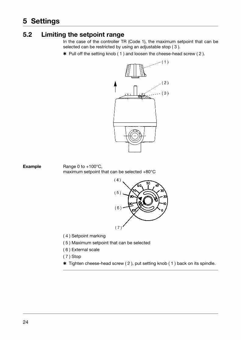
5.2 Limiting the setpoint rangeIn the case of the controller TR (Code 1), the maximum setpoint that can beselected can be restricted by using an adjustable stop ( 3 ).
Pull off the setting knob ( 1 ) and loosen the cheese-head screw ( 2 ).
Example Range 0 to +100°C,maximum setpoint that can be selected +80°C
( 4 ) Setpoint marking
( 5 ) Maximum setpoint that can be selected
( 6 ) External scale
( 7 ) Stop
Tighten cheese-head screw ( 2 ), put setting knob ( 1 ) back on its spindle.
25
5 Settings
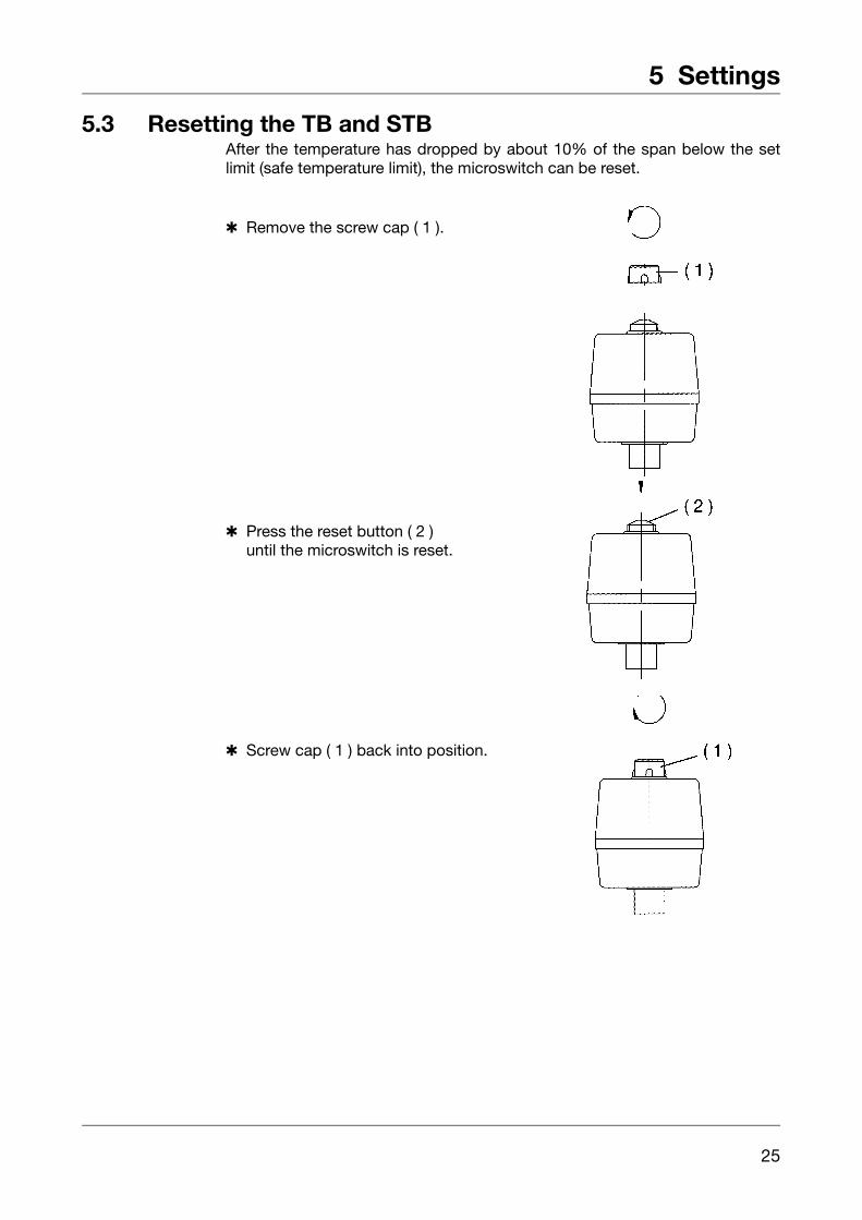
5.3 Resetting the TB and STBAfter the temperature has dropped by about 10% of the span below the setlimit (safe temperature limit), the microswitch can be reset.
Remove the screw cap ( 1 ).
Press the reset button ( 2 )until the microswitch is reset.
Screw cap ( 1 ) back into position.
5 Settings
26
5.4 Self-monitoring
5.4.1 Response to a fracture of the measuring system
5.4.2 Response to falling below the temperature limit
5.5 Use of the STW (STB) as STB
H On the STB and STW (STB), a fracture of the measuring system (leakage) willcause the circuit to open permanently.
On the STB, the microswitch will additionally be locked.
H If the probe cools down to below the minimum temperature of -10°C, the circuitwill open (STW (STB) and STB).
As the probe temperature rises above the minimum probe temperature, theSTB has to be reset manually. Chapter 5.3 “Resetting the TB and STB”, page 25.
The STW resets itself automatically.
V The lock-out function to DIN 3440 must be ensured by a subsequent circuit.This circuit must conform to DIN VDE 0116, Section 8.7.
27
6 Instrument description
6.1 Technical data
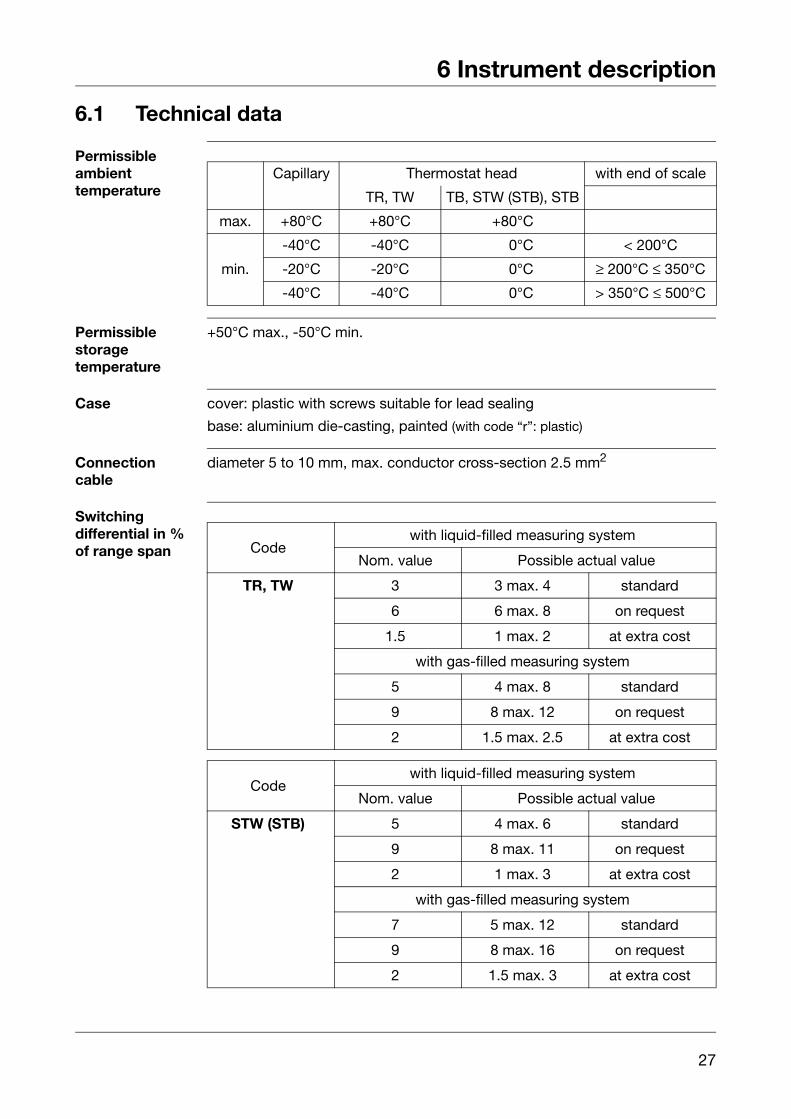
Permissible ambienttemperature
Permissiblestoragetemperature
+50°C max., -50°C min.
Case cover: plastic with screws suitable for lead sealing
base: aluminium die-casting, painted (with code “r”: plastic)
Connectioncable
diameter 5 to 10 mm, max. conductor cross-section 2.5 mm2
Switchingdifferential in %of range span
Capillary Thermostat head with end of scale
TR, TW TB, STW (STB), STB
max. +80°C +80°C +80°C
min.
-40°C -40°C +80°C < 200°C
-20°C -20°C +80°C ≥ 200°C ≤ 350°C
-40°C -40°C +80°C > 350°C ≤ 500°C
Codewith liquid-filled measuring system
Nom. value Possible actual value
TR, TW 3 3 max. 4 standard
6 6 max. 8 on request
1.5 1 max. 2 at extra cost
with gas-filled measuring system
5 4 max. 8 standard
9 8 max. 12 on request
2 1.5 max. 2.5 at extra cost
Codewith liquid-filled measuring system
Nom. value Possible actual value
STW (STB) 5 4 max. 6 standard
9 8 max. 11 on request
2 1 max. 3 at extra cost
with gas-filled measuring system
7 5 max. 12 standard
9 8 max. 16 on request
2 1.5 max. 3 at extra cost
6 Instrument description
28
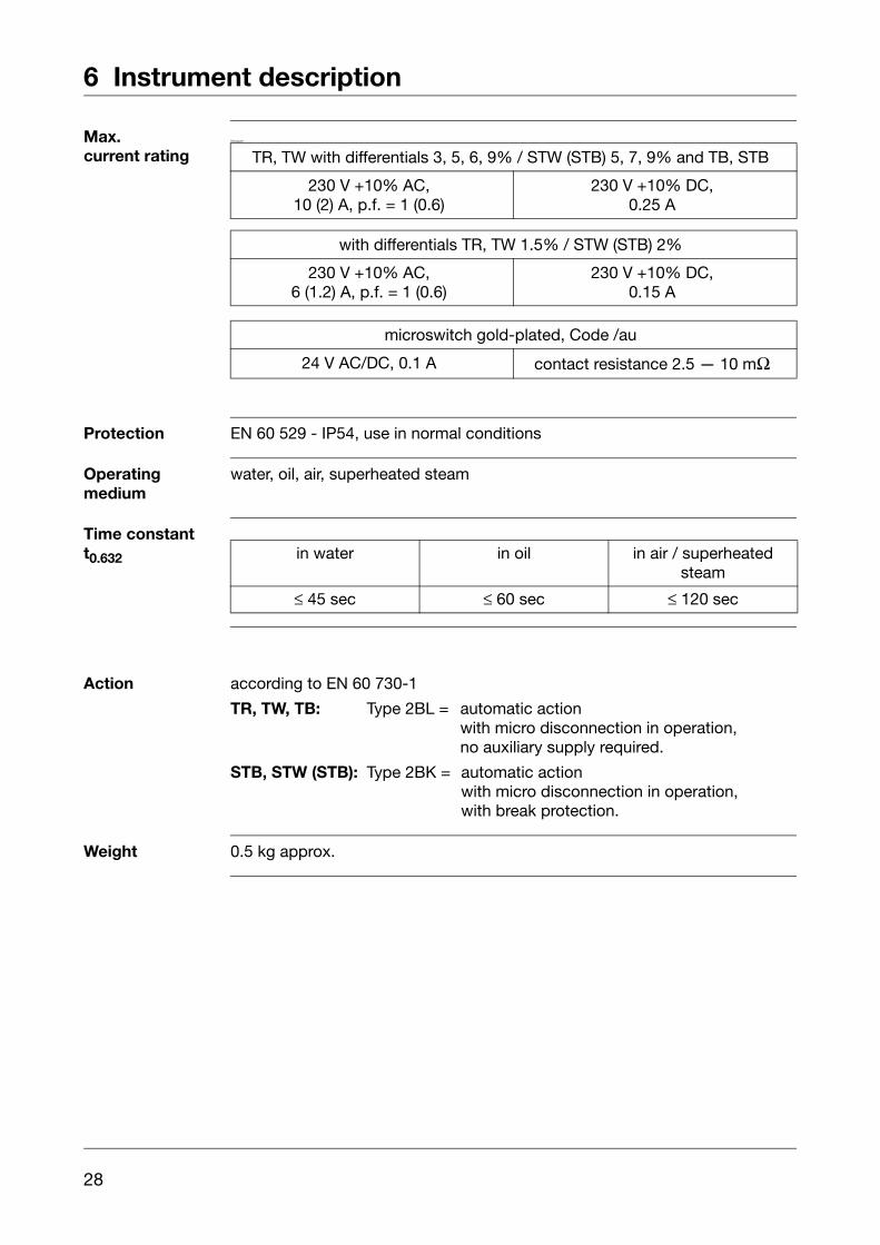
Max.current rating
Schutzart
Protection EN 60 529 - IP54, use in normal conditions
Operatingmedium
water, oil, air, superheated steam
Time constantt0.632
Action according to EN 60 730-1
TR, TW, TB: Type 2BL = automatic actionwith micro disconnection in operation,no auxiliary supply required.
STB, STW (STB): Type 2BK = automatic actionwith micro disconnection in operation,with break protection.
Weight 0.5 kg approx.
TR, TW with differentials 3, 5, 6, 9% / STW (STB) 5, 7, 9% and TB, STB
230 V +10% AC,10 (2) A, p.f. = 1 (0.6)
230 V +10% DC,0.25 A
with differentials TR, TW 1.5% / STW (STB) 2%
230 V +10% AC,6 (1.2) A, p.f. = 1 (0.6)
230 V +10% DC,0.15 A
microswitch gold-plated, Code /au
24 V AC/DC, 0.1 A contact resistance 2.5 — 10 mΩ
in water in oil in air / superheatedsteam
≤ 45 sec ≤ 60 sec ≤ 120 sec

29
6 Instrument description
Material ofcapillary andprobe
Minimumbending radiusof capillary
5 mm
Switching pointaccuracy
in % of scale span,referred to setpoint / limit value at Tamb +22°C
TR in upper third of scale ± 1.5%at start of scale ± 6%
TB, STB, STW (STB) in upper third of scale
at start of scale
Meanambienttemperatureerror
in % of scale span, referred to limit value.
A deviation from the ambient temperature at the thermostat head and / orcapillary from the calibration ambient temperature +22°C produces a shift of the switching point. Higher ambient temperature = lower switching pointLower ambient temperature = higher switching point
End of scale Capillary Probe
up to +200°C copper, Mat. Ref. 2.00901.5 mm dia.
copper, Mat. Ref. 2.0090brazed
up to +350°C copper, Mat. Ref. 2.00901.5 mm dia.
st. steel, Mat. Ref. 1.4571brazed
up to +500°C st. steel, Mat. Ref. 1.45711.5 mm dia.
st. steel, Mat. Ref. 1.4571welded
at extra cost
up to +350°C st. steel, Mat. Ref. 1.45711.5 mm dia.
st. steel, Mat. Ref. 1.4571welded
+0-5 %
+0-10 %
Surface-mounting thermostats with end of scale< +200°C ≥ +200°C ≤ +350°C
TR/TW/TB STB/STW (STB) TR/TW/TB STB/STW (STB)on thermostat head
0.08%/°C 0.17%/°C 0.06%/°C 0.13%/°Con capillary per meter
0.047%/°C 0.054%/°C 0.09 %/°C 0.11%/°C
Surface-mounting thermostats with end of scale≥ +350°C ≤ +500°C
TR/TW/TB STB/STW (STB)on thermostat head
0.14%/°C 0.12%/°Con capillary per meter
0.04 %/°C 0.03 %/°C