Embed Size (px)
Citation preview
Su
rface
-Mo
un
t Fu
se
s –
Fu
nd
am
en
tals
RoHS Compliant, ELV Compliant HF Halogen Free 107
10
Surface-Mount Fuses
Fundamentals
Overview
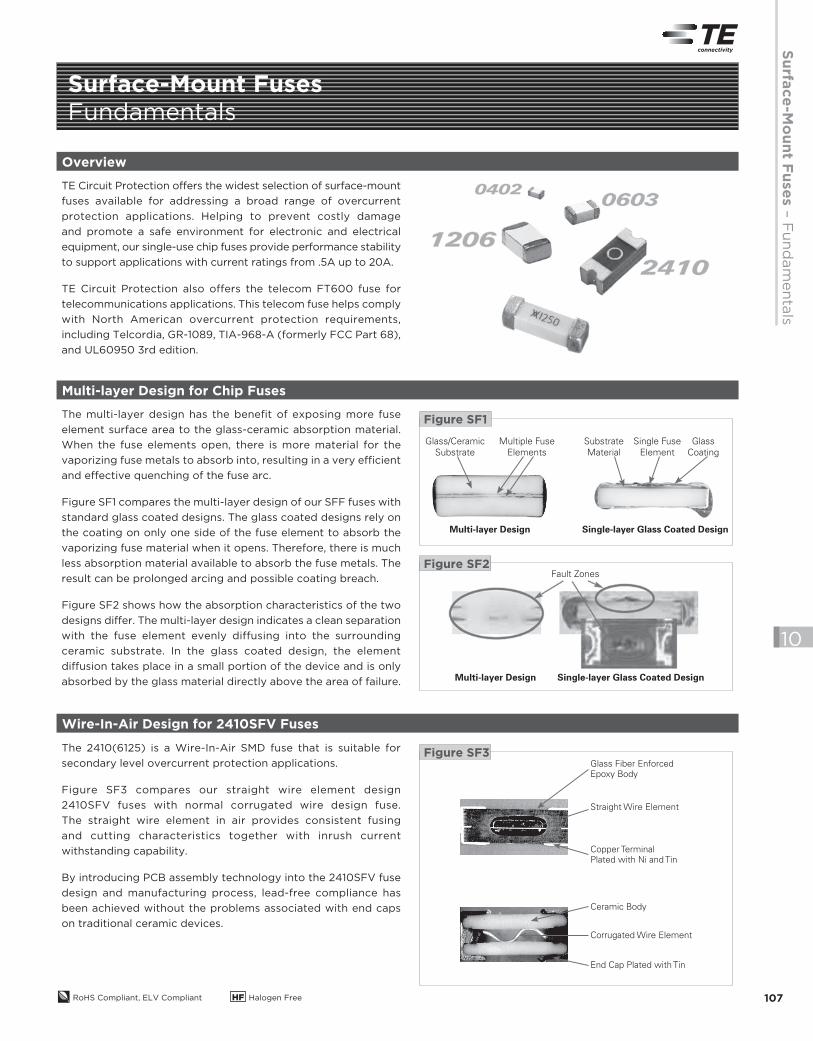
TE Circuit Protection offers the widest selection of surface-mount
fuses available for addressing a broad range of overcurrent
protection applications. Helping to prevent costly damage
and promote a safe environment for electronic and electrical
equipment, our single-use chip fuses provide performance stability
to support applications with current ratings from .5A up to 20A.
TE Circuit Protection also offers the telecom FT600 fuse for
telecommunications applications. This telecom fuse helps comply
with North American overcurrent protection requirements,
including Telcordia, GR-1089, TIA-968-A (formerly FCC Part 68),
and UL60950 3rd edition.
Multi-layer Design for Chip Fuses
The multi-layer design has the benefit of exposing more fuse
element surface area to the glass-ceramic absorption material.
When the fuse elements open, there is more material for the
vaporizing fuse metals to absorb into, resulting in a very efficient
and effective quenching of the fuse arc.
Figure SF1 compares the multi-layer design of our SFF fuses with
standard glass coated designs. The glass coated designs rely on
the coating on only one side of the fuse element to absorb the
vaporizing fuse material when it opens. Therefore, there is much
less absorption material available to absorb the fuse metals. The
result can be prolonged arcing and possible coating breach.
Figure SF2 shows how the absorption characteristics of the two
designs differ. The multi-layer design indicates a clean separation
with the fuse element evenly diffusing into the surrounding
ceramic substrate. In the glass coated design, the element
diffusion takes place in a small portion of the device and is only
absorbed by the glass material directly above the area of failure.
Glass/Ceramic
Substrate
Multiple Fuse
Elements
Substrate
Material
Single Fuse
Element
Single-layer Glass Coated DesignMulti-layer Design
Glass
Coating
Figure SF1
Figure SF2Fault Zones
Multi-layer Design Single-layer Glass Coated Design
Wire-In-Air Design for 2410SFV Fuses
The 2410(6125) is a Wire-In-Air SMD fuse that is suitable for
secondary level overcurrent protection applications.
Figure SF3 compares our straight wire element design
2410SFV fuses with normal corrugated wire design fuse.
The straight wire element in air provides consistent fusing
and cutting characteristics together with inrush current
withstanding capability.
By introducing PCB assembly technology into the 2410SFV fuse
design and manufacturing process, lead-free compliance has
been achieved without the problems associated with end caps
on traditional ceramic devices.
Glass Fiber EnforcedEpoxy Body
Ceramic Body
Corrugated Wire Element
End Cap Plated with Tin
Straight Wire Element
Copper Terminal Plated with Ni and Tin
Figure SF3
2013_CP_S10-Fuses-1-Fundamentals.indd 107 8/3/13 10:58 AM
RoHS Compliant, ELV Compliant HF Halogen Free108
10
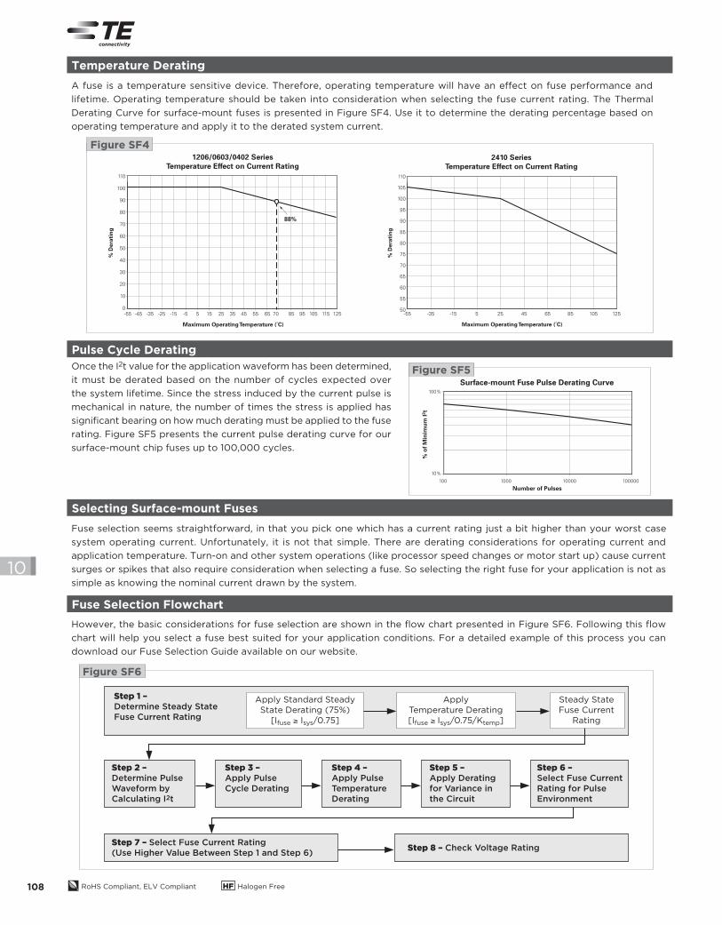
Pulse Cycle Derating
Once the I2t value for the application waveform has been determined,
it must be derated based on the number of cycles expected over
the system lifetime. Since the stress induced by the current pulse is
mechanical in nature, the number of times the stress is applied has
significant bearing on how much derating must be applied to the fuse
rating. Figure SF5 presents the current pulse derating curve for our
surface-mount chip fuses up to 100,000 cycles.
Fuse Selection Flowchart
However, the basic considerations for fuse selection are shown in the flow chart presented in Figure SF6. Following this flow
chart will help you select a fuse best suited for your application conditions. For a detailed example of this process you can
download our Fuse Selection Guide available on our website.
Surface-mount Fuse Pulse Derating Curve
100 1000 10000 100000
100%
10%
Number of Pulses
% o
f M
inim
um
I2t
Figure SF5
Step 1 –
Determine Steady State
Fuse Current Rating
Step 2 –
Determine Pulse
Waveform by
Calculating I2t
Step 3 –
Apply Pulse
Cycle Derating
Step 4 –
Apply Pulse
Temperature
Derating
Step 5 –
Apply Derating
for Variance in
the Circuit
Step 6 –
Select Fuse Current
Rating for Pulse
Environment
Step 7 – Select Fuse Current Rating
(Use Higher Value Between Step 1 and Step 6)Step 8 – Check Voltage Rating
Apply Standard Steady State Derating (75%)
[Ifuse ≥ Isys/0.75]
Apply Temperature Derating[Ifuse ≥ Isys/0.75/Ktemp]
Steady StateFuse Current
Rating
Figure SF6
Selecting Surface-mount Fuses
Fuse selection seems straightforward, in that you pick one which has a current rating just a bit higher than your worst case
system operating current. Unfortunately, it is not that simple. There are derating considerations for operating current and
application temperature. Turn-on and other system operations (like processor speed changes or motor start up) cause current
surges or spikes that also require consideration when selecting a fuse. So selecting the right fuse for your application is not as
simple as knowing the nominal current drawn by the system.
Temperature Derating
A fuse is a temperature sensitive device. Therefore, operating temperature will have an efect on fuse performance and
lifetime. Operating temperature should be taken into consideration when selecting the fuse current rating. The Thermal
Derating Curve for surface-mount fuses is presented in Figure SF4. Use it to determine the derating percentage based on
operating temperature and apply it to the derated system current.
1206/0603/0402 SeriesTemperature Effect on Current Rating
% D
era
tin
g
110
100
90
80
70
60
50
40
30
20
10
0
Maximum Operating Temperature (˚C)
-55 -35-45 -15-25 5-5 2515 4535 65 7055 85
88%
10595 125115
Figure SF42410 Series
Temperature Effect on Current Rating
% D
era
tin
g
110
105
100
95
90
85
80
75
70
65
60
55
50
Maximum Operating Temperature (˚C)
-55 -35 -15 5 25 45 65 85 105 125
2013_CP_S10-Fuses-1-Fundamentals.indd 108 8/14/13 9:21 AM
Su
rface
-Mo
un
t Fu
se
s –
Pu
lse T
ole
ran
t Ch
ip F
uses
RoHS Compliant, ELV Compliant HF Halogen Free 109
10
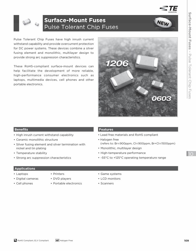
Pulse Tolerant Chip Fuses have high inrush current
withstand capability and provide overcurrent protection
for DC power systems. These devices combine a silver
fusing element and monolithic, multilayer design to
provide strong arc suppression characteristics.
These RoHS-compliant surface-mount devices can
help facilitate the development of more reliable,
high-performance consumer electronics such as
laptops, multimedia devices, cell phones and other
portable electronics.
• High inrush current withstand capability
• Ceramic monolithic structure
• Silver fusing element and silver termination with
nickel and tin plating
• Temperature stability
• Strong arc suppression characteristics
• Lead free materials and RoHS compliant
• Halogen free
(refers to: Br#900ppm, Cl#900ppm, Br+Cl#1500ppm)
• Monolithic, multilayer design
• High-temperature performance
• -55°C to +125°C operating temperature range
• Laptops
• Digital cameras
• Cell phones
Benefits Features
Applications
• Printers
• DVD players
• Portable electronics
• Game systems
• LCD monitors
• Scanners
Surface-Mount Fuses
Pulse Tolerant Chip FusesNEWNENENENEWWWWNEW
2013_CP_S10-Fuses-2-SFP-PulseTolerant.indd 109 8/3/13 10:58 AM
RoHS Compliant, ELV Compliant HF Halogen Free110
10
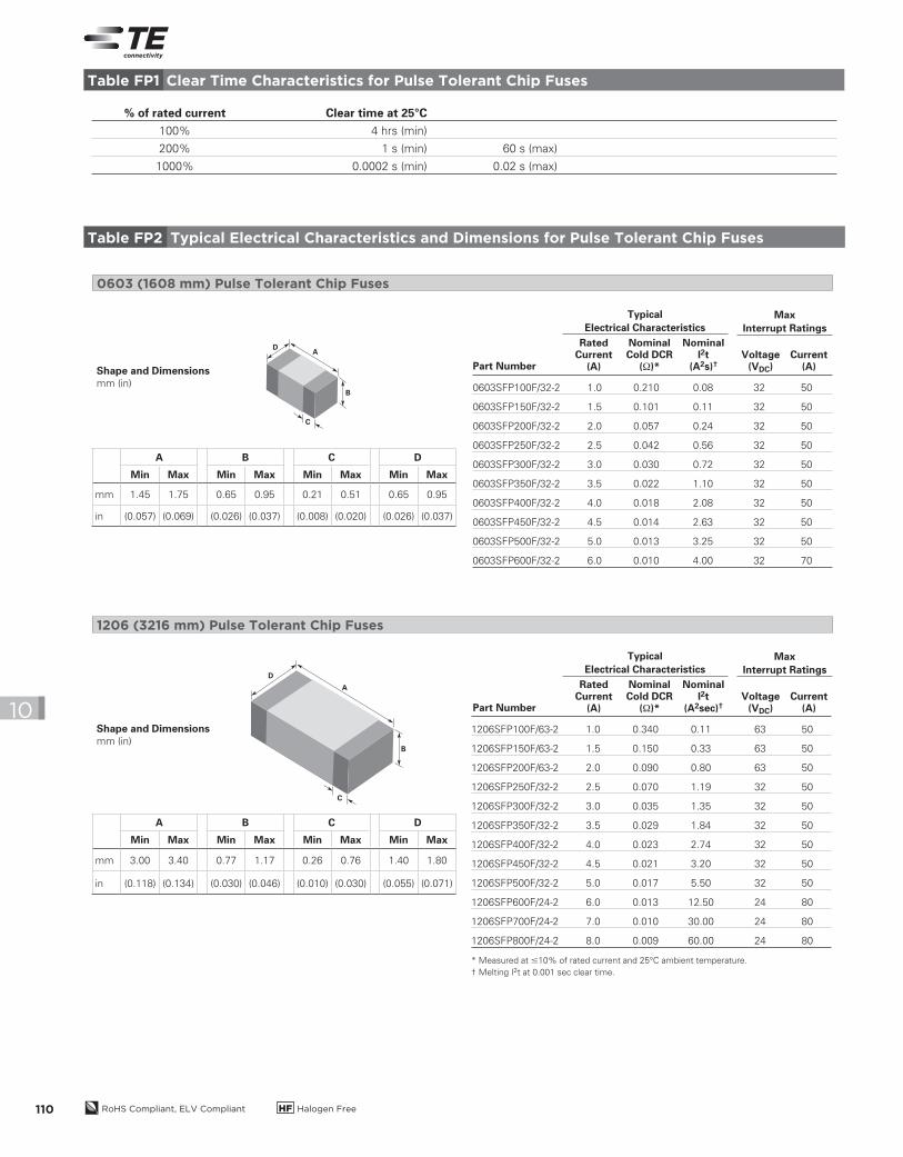
% of rated current Clear time at 25°C
100% 4 hrs (min)
200% 1 s (min) 60 s (max)
1000% 0.0002 s (min) 0.02 s (max)
0603SFP100F/32-2 1.0 0.210 0.08 32 50
0603SFP150F/32-2 1.5 0.101 0.11 32 50
0603SFP200F/32-2 2.0 0.057 0.24 32 50
0603SFP250F/32-2 2.5 0.042 0.56 32 50
0603SFP300F/32-2 3.0 0.030 0.72 32 50
0603SFP350F/32-2 3.5 0.022 1.10 32 50
0603SFP400F/32-2 4.0 0.018 2.08 32 50
0603SFP450F/32-2 4.5 0.014 2.63 32 50
0603SFP500F/32-2 5.0 0.013 3.25 32 50
0603SFP600F/32-2 6.0 0.010 4.00 32 70
1206SFP100F/63-2 1.0 0.340 0.11 63 50
1206SFP150F/63-2 1.5 0.150 0.33 63 50
1206SFP200F/63-2 2.0 0.090 0.80 63 50
1206SFP250F/32-2 2.5 0.070 1.19 32 50
1206SFP300F/32-2 3.0 0.035 1.35 32 50
1206SFP350F/32-2 3.5 0.029 1.84 32 50
1206SFP400F/32-2 4.0 0.023 2.74 32 50
1206SFP450F/32-2 4.5 0.021 3.20 32 50
1206SFP500F/32-2 5.0 0.017 5.50 32 50
1206SFP600F/24-2 6.0 0.013 12.50 24 80
1206SFP700F/24-2 7.0 0.010 30.00 24 80
1206SFP800F/24-2 8.0 0.009 60.00 24 80
* Measured at #10% of rated current and 25°C ambient temperature.
† Melting I2t at 0.001 sec clear time.
0603 (1608 mm) Pulse Tolerant Chip Fuses
1206 (3216 mm) Pulse Tolerant Chip Fuses
A
B
C
D
Shape and Dimensionsmm (in)
Table FP1 Clear Time Characteristics for Pulse Tolerant Chip Fuses
Table FP2 Typical Electrical Characteristics and Dimensions for Pulse Tolerant Chip Fuses
Part Number
RatedCurrent
(A)
NominalCold DCR
(Ω)*Voltage
(VDC)Current
(A)
NominalI2t
(A2s)†
Typical
Electrical Characteristics
Max
Interrupt Ratings
Part Number
RatedCurrent
(A)
NominalCold DCR
(Ω)*Voltage
(VDC)Current
(A)
NominalI2t
(A2sec)†
Typical
Electrical Characteristics
Max
Interrupt Ratings
A B C D
Min Max Min Max Min Max Min Max
mm 1.45 1.75 0.65 0.95 0.21 0.51 0.65 0.95
in (0.057) (0.069) (0.026) (0.037) (0.008) (0.020) (0.026) (0.037)
A B C D
Min Max Min Max Min Max Min Max
mm 3.00 3.40 0.77 1.17 0.26 0.76 1.40 1.80
in (0.118) (0.134) (0.030) (0.046) (0.010) (0.030) (0.055) (0.071)
A
B
C
D
Shape and Dimensionsmm (in)
2013_CP_S10-Fuses-2-SFP-PulseTolerant.indd 110 8/3/13 10:58 AM
Su
rface
-Mo
un
t Fu
se
s –
Pu
lse T
ole
ran
t Ch
ip F
uses
RoHS Compliant, ELV Compliant HF Halogen Free 111
10
I2t (A
2s)
10,000
1000
100
10
1
0.1
0.010.010.001 100.1 1 100
Time (s)
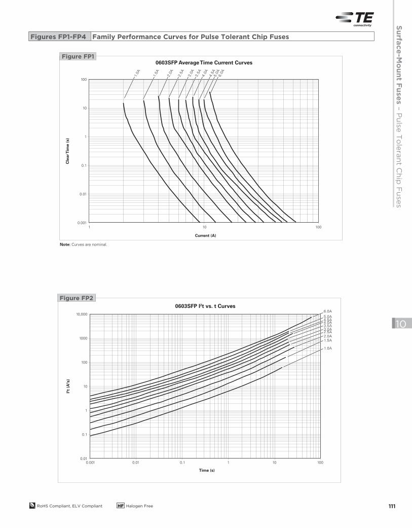
0603SFP I2t vs. t Curves
1.0A
1.5A2.0A2.5A3.0A3.5A4.0A4.5A5.0A
6.0A
Figure FP1
Figure FP2
Note: Curves are nominal.
Figures FP1-FP4 Family Performance Curves for Pulse Tolerant Chip Fuses
Cle
ar T
ime (
s)
100
10
1
0.1
0.01
0.001
10 1001
Current (A)
0603SFP Average Time Current Curves
1.0
A
1.5
A
2.0
A
2.5
A
3.0
A
3.5
A
4.0
A
4.5
A5.0
A6.0
A
2013_CP_S10-Fuses-2-SFP-PulseTolerant.indd 111 8/3/13 10:58 AM
RoHS Compliant, ELV Compliant HF Halogen Free112
10
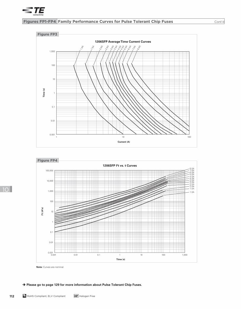
Note: Curves are nominal.
Please go to page 129 for more information about Pulse Tolerant Chip Fuses.
Figures FP1-FP4 Family Performance Curves for Pulse Tolerant Chip Fuses Cont’d
Tim
e (s)
1,000
100
10
1
0.1
0.01
0.00110 1001
Current (A)
1206SFP Average Time Current Curves
1.0A
1.5A
2.0
A
2.5
A
3.0
A3.5
A4.0
A4.5
A5.0
A6.0
A
7.0A
8.0
A
Figure FP3
I2t (A
2s)
100,000
10,000
1,000
100
10
1
0.1
0.01
0.0010.01 0.1 1 10010 1,0000.001
Time (s)
1206SFP I2t vs. t Curves
1.0A
1.5A2.0A2.5A3.0A3.5A4.0A4.5A5.0A6.0A7.0A8.0A
Figure FP4
2013_CP_S10-Fuses-2-SFP-PulseTolerant.indd 112 8/3/13 10:58 AM
Su
rface
-Mo
un
t Fu
se
s –
06
03
Very
Fast-A
ctin
g C
hip
Fu
ses
RoHS Compliant, ELV Compliant HF Halogen Free 113
10
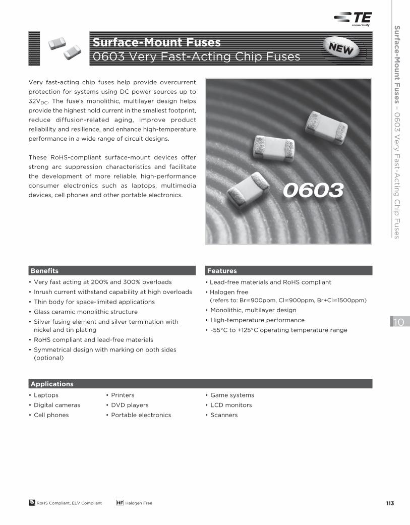
Very fast-acting chip fuses help provide overcurrent
protection for systems using DC power sources up to
32VDC. The fuse’s monolithic, multilayer design helps
provide the highest hold current in the smallest footprint,
reduce diffusion-related aging, improve product
reliability and resilience, and enhance high-temperature
performance in a wide range of circuit designs.
These RoHS-compliant surface-mount devices offer
strong arc suppression characteristics and facilitate
the development of more reliable, high-performance
consumer electronics such as laptops, multimedia
devices, cell phones and other portable electronics.
• Very fast acting at 200% and 300% overloads
• Inrush current withstand capability at high overloads
• Thin body for space-limited applications
• Glass ceramic monolithic structure
• Silver fusing element and silver termination with
nickel and tin plating
• RoHS compliant and lead-free materials
• Symmetrical design with marking on both sides
(optional)
• Lead-free materials and RoHS compliant
• Halogen free
(refers to: Br#900ppm, Cl#900ppm, Br+Cl#1500ppm)
• Monolithic, multilayer design
• High-temperature performance
• -55°C to +125°C operating temperature range
• Laptops
• Digital cameras
• Cell phones
Benefits Features
Applications
• Printers
• DVD players
• Portable electronics
• Game systems
• LCD monitors
• Scanners
Surface-Mount Fuses
0603 Very Fast-Acting Chip FusesNEWNENENENEWWWWNEW
2013_CP_S10-Fuses-3-SFV-0603-Very-Fast-Acting.indd 113 8/3/13 10:58 AM
RoHS Compliant, ELV Compliant HF Halogen Free114
10
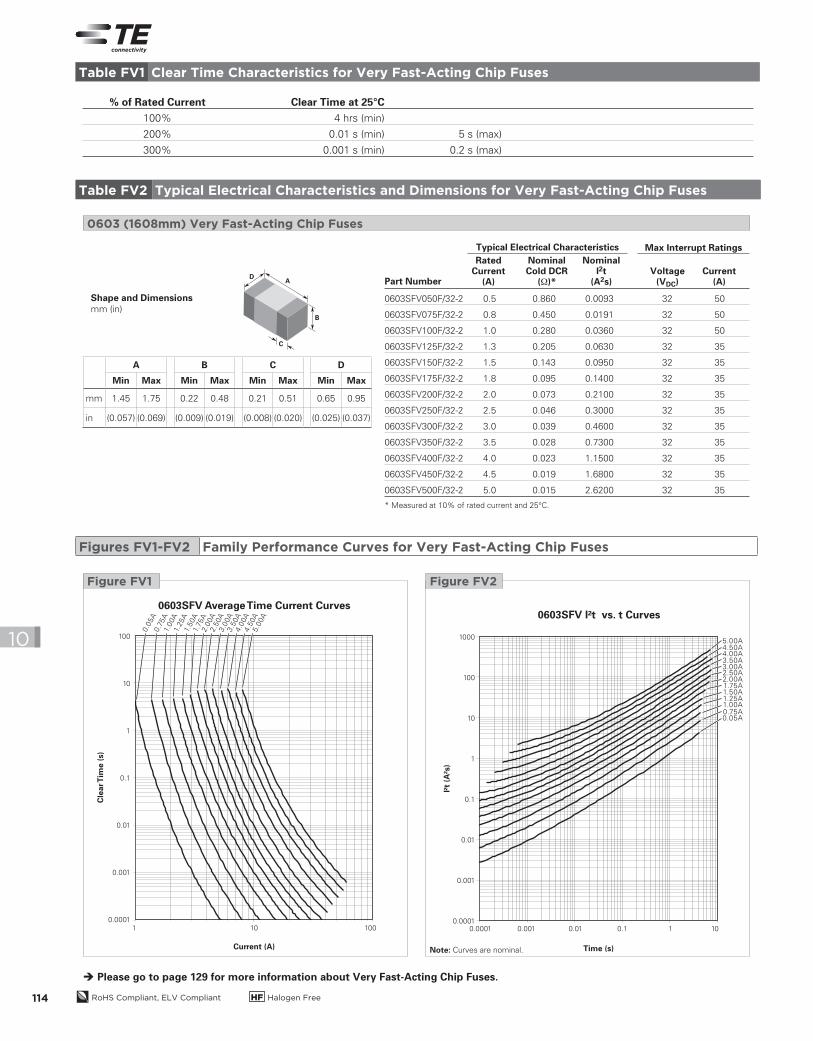
% of Rated Current Clear Time at 25°C
100% 4 hrs (min)
200% 0.01 s (min) 5 s (max)
300% 0.001 s (min) 0.2 s (max)
0603SFV050F/32-2 0.5 0.860 0.0093 32 50
0603SFV075F/32-2 0.8 0.450 0.0191 32 50
0603SFV100F/32-2 1.0 0.280 0.0360 32 50
0603SFV125F/32-2 1.3 0.205 0.0630 32 35
0603SFV150F/32-2 1.5 0.143 0.0950 32 35
0603SFV175F/32-2 1.8 0.095 0.1400 32 35
0603SFV200F/32-2 2.0 0.073 0.2100 32 35
0603SFV250F/32-2 2.5 0.046 0.3000 32 35
0603SFV300F/32-2 3.0 0.039 0.4600 32 35
0603SFV350F/32-2 3.5 0.028 0.7300 32 35
0603SFV400F/32-2 4.0 0.023 1.1500 32 35
0603SFV450F/32-2 4.5 0.019 1.6800 32 35
0603SFV500F/32-2 5.0 0.015 2.6200 32 35
* Measured at 10% of rated current and 25°C.
0603 (1608mm) Very Fast-Acting Chip Fuses
A
B
C
D
Shape and Dimensionsmm (in)
Table FV1 Clear Time Characteristics for Very Fast-Acting Chip Fuses
Table FV2 Typical Electrical Characteristics and Dimensions for Very Fast-Acting Chip Fuses
Part Number
RatedCurrent
(A)
NominalCold DCR
(Ω)*Voltage
(VDC)Current
(A)
NominalI2t
(A2s)
Typical Electrical Characteristics Max Interrupt Ratings
Please go to page 129 for more information about Very Fast-Acting Chip Fuses.
1 10010
Cle
ar T
ime (
s)
100
10
1
0.1
0.01
0.001
0.0001
Current (A)
0603SFV Average Time Current Curves
0.0
5A
0.7
5A
1.00A
1.25A
1.50A
1.75A
2.0
0A
2.5
0A
3.0
0A
3.5
0A
4.0
0A
4.5
0A
5.0
0A 0603SFV I²t vs. t Curves
I²t
(A²s
)
Time (s)
1000
100
10
1
0.1
0.01
0.001
0.00010.0001 0.001 0.10.01 1 10
5.00A4.50A4.00A3.50A3.00A2.50A2.00A1.75A
0.75A0.05A
1.25A1.50A
1.00A
Figure FV2Figure FV1
Note: Curves are nominal.
Figures FV1-FV2 Family Performance Curves for Very Fast-Acting Chip Fuses
A B C D
Min Max Min Max Min Max Min Max
mm 1.45 1.75 0.22 0.48 0.21 0.51 0.65 0.95
in (0.057) (0.069) (0.009) (0.019) (0.008) (0.020) (0.025) (0.037)
2013_CP_S10-Fuses-3-SFV-0603-Very-Fast-Acting.indd 114 8/3/13 10:58 AM
Su
rface
-Mo
un
t Fu
se
s –
Fast-A
ctin
g C
hip
Fu
ses
RoHS Compliant, ELV Compliant HF Halogen Free 115
10
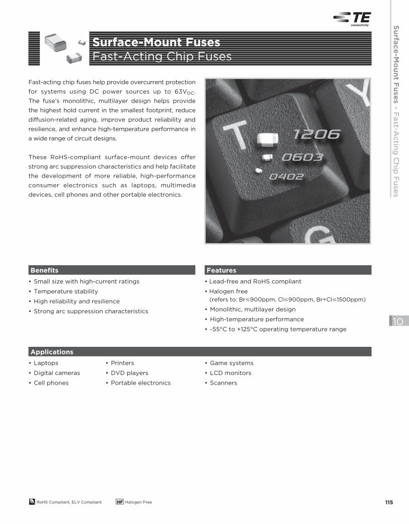
Fast-acting chip fuses help provide overcurrent protection
for systems using DC power sources up to 63VDC.
The fuse’s monolithic, multilayer design helps provide
the highest hold current in the smallest footprint, reduce
diffusion- related aging, improve product reliability and
resilience, and enhance high-temperature performance in
a wide range of circuit designs.
These RoHS-compliant surface-mount devices offer
strong arc suppression characteristics and help facilitate
the development of more reliable, high-performance
consumer electronics such as laptops, multimedia
devices, cell phones and other portable electronics.
• Small size with high-current ratings
• Temperature stability
• High reliability and resilience
• Strong arc suppression characteristics
• Lead-free and RoHS compliant
• Halogen free
(refers to: Br#900ppm, Cl#900ppm, Br+Cl#1500ppm)
• Monolithic, multilayer design
• High-temperature performance
• -55°C to +125°C operating temperature range
• Laptops
• Digital cameras
• Cell phones
Benefits Features
Applications
• Printers
• DVD players
• Portable electronics
• Game systems
• LCD monitors
• Scanners
Surface-Mount Fuses
Fast-Acting Chip Fuses
2013_CP_S10-Fuses-4-FF-FastActing.indd 115 8/3/13 10:59 AM
RoHS Compliant, ELV Compliant HF Halogen Free116
10
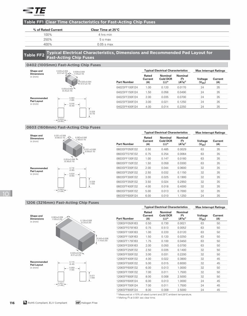
% of Rated Current Clear Time at 25°C
100% 4 hrs min
250% 5 s max
400% 0.05 s max
0402SFF100F/24 1.00 0.120 0.0170 24 35
0402SFF150F/24 1.50 0.056 0.0490 24 35
0402SFF200F/24 2.00 0.035 0.0700 24 35
0402SFF300F/24 3.00 0.021 0.1250 24 35
0402SFF400F/24 4.00 0.014 0.2250 24 35
0603SFF050F/32 0.50 0.485 0.0029 63 35
0603SFF075F/32 0.75 0.254 0.0064 63 35
0603SFF100F/32 1.00 0.147 0.0160 63 35
0603SFF150F/32 1.50 0.059 0.0300 63 35
0603SFF200F/32 2.00 0.044 0.0600 32 35
0603SFF250F/32 2.50 0.032 0.1150 32 35
0603SFF300F/32 3.00 0.025 0.1900 32 35
0603SFF350F/32 3.50 0.024 0.2950 32 35
0603SFF400F/32 4.00 0.018 0.4000 32 35
0603SFF500F/32 5.00 0.013 0.7000 32 35
0603SFF600F/24 6.00 0.010 1.1250 24 35
1206SFF050F/63 0.50 0.730 0.0021 63 50
1206SFF075F/63 0.75 0.513 0.0052 63 50
1206SFF100F/63 1.00 0.220 0.0120 63 50
1206SFF150F/63 1.50 0.120 0.0250 63 50
1206SFF175F/63 1.75 0.100 0.0450 63 50
1206SFF200F/63 2.00 0.050 0.0700 63 50
1206SFF250F/32 2.50 0.035 0.1400 32 50
1206SFF300F/32 3.00 0.031 0.2200 32 50
1206SFF400F/32 4.00 0.022 0.3800 32 45
1206SFF500F/32 5.00 0.015 0.6000 32 45
1206SFF600F/32 6.00 0.013 1.0000 32 50
1206SFF700F/32 7.00 0.011 1.7500 32 50
1206SFF800F/32 8.00 0.008 2.5000 32 50
1206SFF600F/24 6.00 0.013 1.0000 24 45
1206SFF700F/24 7.00 0.011 1.7500 24 45
1206SFF800F/24 8.00 0.008 2.5000 24 45
* Measured at #10% of rated current and 25°C ambient temperature.
† Melting I2t at 0.001 sec clear time.
0402 (1005mm) Fast-Acting Chip Fuses
0603 (1608mm) Fast-Acting Chip Fuses
1206 (3216mm) Fast-Acting Chip Fuses
0.063(1.60)
0.039±0.004(1.00±0.10)
0.020±0.004(0.51±0.10)
0.010±0.004(0.25±0.10)
0.020±0.004(0.51±0.10)
Shape andDimensionsin (mm)
RecommendedPad Layoutin (mm)
0.028(0.70)
0.024(0.60)
0.016(0.40)
Shape andDimensionsin (mm)
RecommendedPad Layoutin (mm)
0.031±0.006(0.80±0.15)
0.031±0.006(0.80±0.15)
0.014±0.006(0.36±0.15)
0.063±0.006(1.60±0.15)
0.110(2.80)
0.039(1.00)
0.043(1.09)
0.024(0.60)
Shape andDimensionsin (mm)
RecommendedPad Layoutin (mm)
0.063±0.008(1.60±0.20)
0.126±0.008(3.20±0.20)
0.043±0.008(1.10±0.20)
0.020±0.010(0.51±0.25)
0.173(4.40)
0.071(1.80)
0.057(1.45)
0.059(1.50)
Table FF1 Clear Time Characteristics for Fast-Acting Chip Fuses
Table FF2Typical Electrical Characteristics, Dimensions and Recommended Pad Layout for
Fast-Acting Chip Fuses
Part Number
RatedCurrent
(A)
NominalCold DCR
(Ω)*Voltage
(VDC)Current
(A)
NominalI2t
(A2s)†
Typical Electrical Characteristics Max Interrupt Ratings
Part Number
RatedCurrent
(A)
NominalCold DCR
(Ω)*Voltage
(VDC)Current
(A)
NominalI2t
(A2s)†
Typical Electrical Characteristics Max Interrupt Ratings
Part Number
RatedCurrent
(A)
NominalCold DCR
(Ω)*Voltage
(VDC)Current
(A)
NominalI2t
(A2s)†
Typical Electrical Characteristics Max Interrupt Ratings
2013_CP_S10-Fuses-4-FF-FastActing.indd 116 8/3/13 10:59 AM
Su
rface
-Mo
un
t Fu
se
s –
Fast-A
ctin
g C
hip
Fu
ses
RoHS Compliant, ELV Compliant HF Halogen Free 117
10
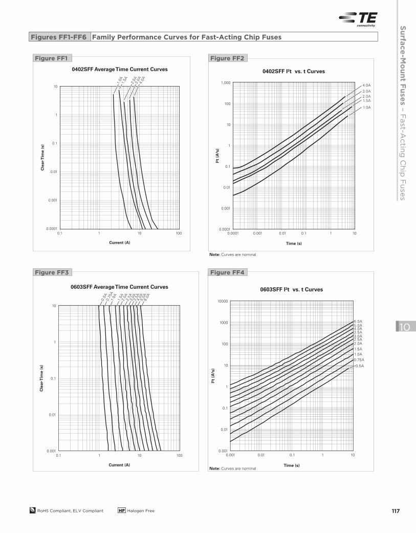
10
1
0.1
0.01
0.001
10.1 10 100
Current (A)
Cle
ar-
Tim
e (
s)
0603SFF Average Time Current Curves
0.5
A0.7
5A
1.0A
1.5A
2.0
A2.5
A3.0
A3.5
A4.0
A5.0
A6.0
A
0.001 0.01 0.1 1 10
10000
1000
100
10
1
0.1
0.01
0.001
I²t
(A²s
)
Time (s)
0603SFF I²t vs. t Curves
0.5A
0.75A
1.0A
1.5A
2.0A2.5A3.0A3.5A4.0A5.0A6.0A
Figure FF4Figure FF3
Note: Curves are nominal
Note: Curves are nominal
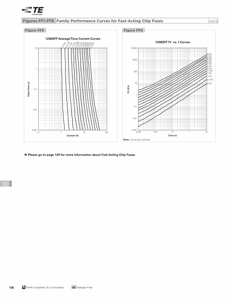
Figures FF1-FF6 Family Performance Curves for Fast-Acting Chip Fuses
0.1 101 100
Clear-Tim
e (s)
10
1
0.1
0.01
0.001
0.0001
Current (A)
0402SFF Average Time Current Curves
1.0A
1.5A
2.0
A3.0
A4.0
A
Figure FF1
0.0010.0001 0.01 0.1 1 10
1,000
100
10
1
0.1
0.01
0.001
0.0001
I²t (A²s)
Time (s)
0402SFF I²t vs. t Curves
1.0A
1.5A2.0A
3.0A
4.0A
Figure FF2
2013_CP_S10-Fuses-4-FF-FastActing.indd 117 8/3/13 10:59 AM
RoHS Compliant, ELV Compliant HF Halogen Free118
10
0.1 101 100
Cle
ar-
Tim
e (
s)
10
1
0.1
0.01
0.001
Current (A)
1206SFF Average Time Current Curves
0.5
A0.7
5A
1.0A
1.5A
1.75A
2.0
A2.5
A3.0
A4.0
A5.0
A6.0
A7.
0A
8.0
A
I²t
(A²s
)
10000
1000
100
10
1
0.1
0.01
0.001
Time (s)
1206SFF I²t vs. t Curves
0.001 0.01 0.1 1 10
0.5A
0.75A
1.0A
1.5A1.75A2.0A2.5A
3.0A4.0A5.0A6.0A7.0A8.0A
Figure FF6Figure FF5
Note: Curves are nominal.
Please go to page 129 for more information about Fast-Acting Chip Fuses.
Figures FF1-FF6 Family Performance Curves for Fast-Acting Chip Fuses Cont’d
2013_CP_S10-Fuses-4-FF-FastActing.indd 118 8/3/13 10:59 AM
RoHS Compliant, ELV Compliant HF Halogen Free 119
Su
rface
-Mo
un
t Fu
se
s –
Hig
h-C
urre
nt-R
ate
d C
hip
Fu
ses
10
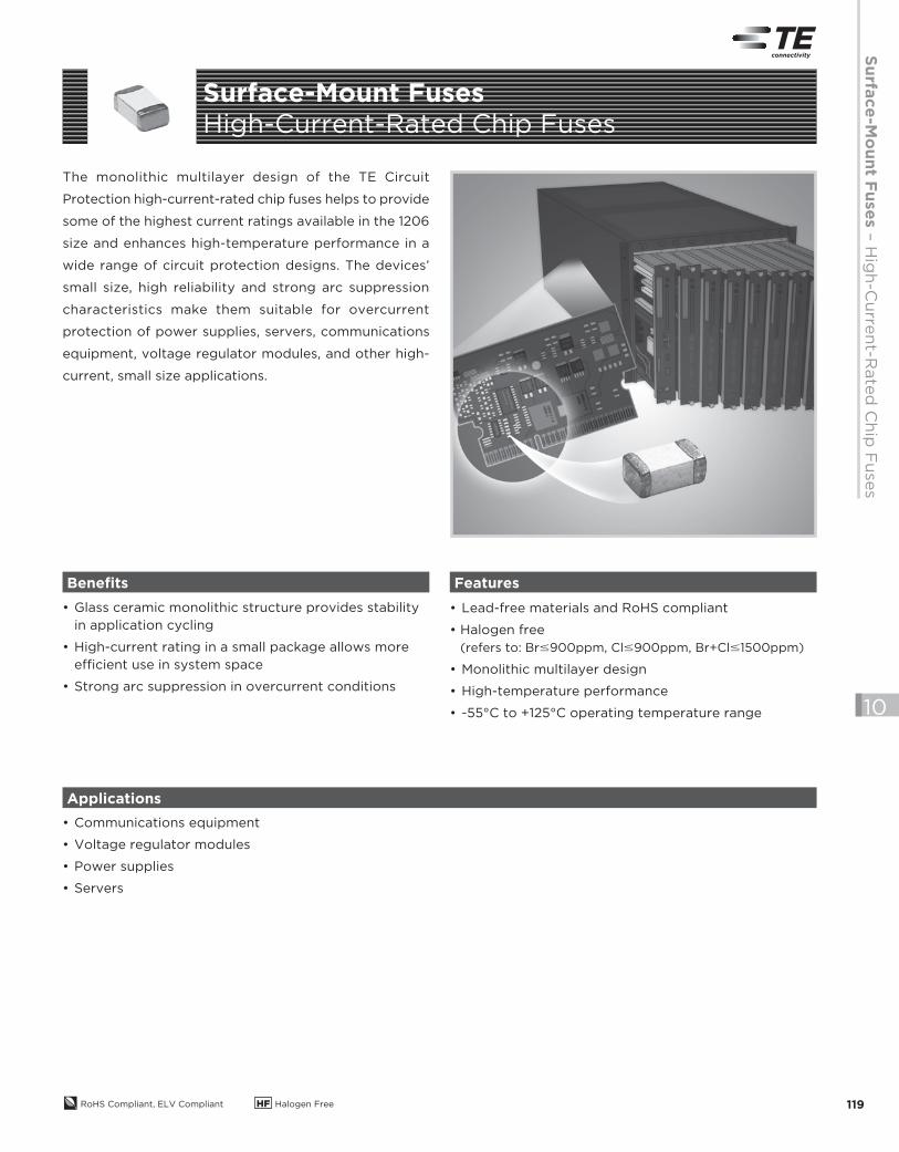
The monolithic multilayer design of the TE Circuit
Protection high-current-rated chip fuses helps to provide
some of the highest current ratings available in the 1206
size and enhances high-temperature performance in a
wide range of circuit protection designs. The devices’
small size, high reliability and strong arc suppression
characteristics make them suitable for overcurrent
protection of power supplies, servers, communications
equipment, voltage regulator modules, and other high-
current, small size applications.
• Glass ceramic monolithic structure provides stability
in application cycling
• High-current rating in a small package allows more
efficient use in system space
• Strong arc suppression in overcurrent conditions
• Lead-free materials and RoHS compliant
• Halogen free
(refers to: Br#900ppm, Cl#900ppm, Br+Cl#1500ppm)
• Monolithic multilayer design
• High-temperature performance
• -55°C to +125°C operating temperature range
• Communications equipment
• Voltage regulator modules
• Power supplies
• Servers
Benefits Features
Applications
Surface-Mount Fuses
High-Current-Rated Chip Fuses
2013_CP_S10-Fuses-5-FH-HighCurrent.indd 119 8/3/13 10:59 AM
RoHS Compliant, ELV Compliant HF Halogen Free120
10
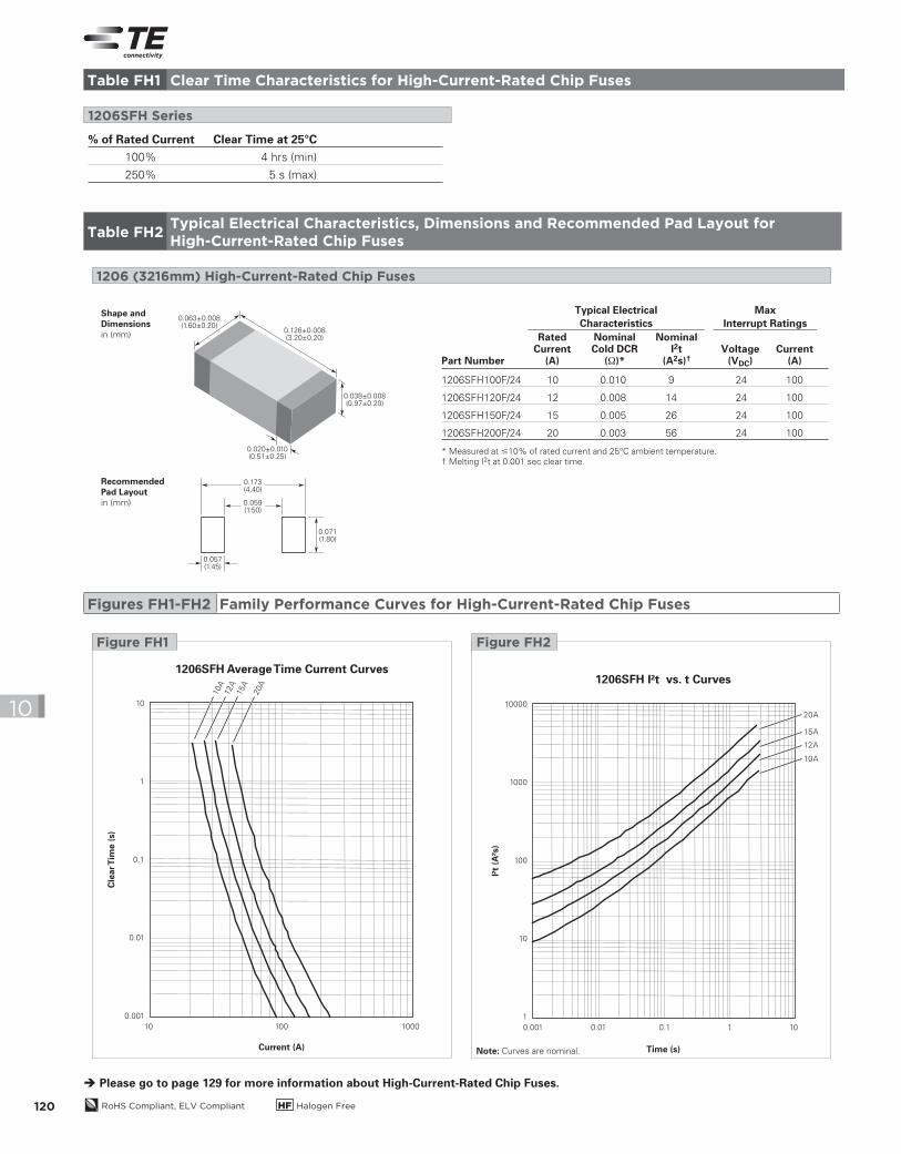
% of Rated Current Clear Time at 25°C
100% 4 hrs (min)
250% 5 s (max)
1206SFH Series
1206SFH100F/24 10 0.010 9 24 100
1206SFH120F/24 12 0.008 14 24 100
1206SFH150F/24 15 0.005 26 24 100
1206SFH200F/24 20 0.003 56 24 100
* Measured at #10% of rated current and 25°C ambient temperature.
† Melting I2t at 0.001 sec clear time.
Part Number
RatedCurrent
(A)
NominalCold DCR
(Ω)*Voltage
(VDC)Current
(A)
1206 (3216mm) High-Current-Rated Chip Fuses
Shape andDimensionsin (mm)
RecommendedPad Layoutin (mm)
0.063±0.008(1.60±0.20)
0.126±0.008(3.20±0.20)
0.038±0.008(0.97±0.20)
0.020±0.010(0.51±0.25)
0.173(4.40)
0.071(1.80)
0.057(1.45)
0.059(1.50)
NominalI2t
(A2s)†
Typical Electrical
Characteristics
Max
Interrupt Ratings
10 1000100
Cle
ar T
ime (
s)
10
1
0.1
0.01
0.001
Current (A)
1206SFH Average Time Current Curves
10A
12A
15A
20A
0.001 0.01 0.1 1 10
10000
1000
100
10
1
I²t
(A²s
)
Time (s)
1206SFH I²t vs. t Curves
20A
15A
12A
10A
Figure FH2Figure FH1
Note: Curves are nominal.
Table FH1 Clear Time Characteristics for High-Current-Rated Chip Fuses
Table FH2Typical Electrical Characteristics, Dimensions and Recommended Pad Layout for
High-Current-Rated Chip Fuses
Figures FH1-FH2 Family Performance Curves for High-Current-Rated Chip Fuses
Please go to page 129 for more information about High-Current-Rated Chip Fuses.
2013_CP_S10-Fuses-5-FH-HighCurrent.indd 120 8/3/13 10:59 AM
Su
rface
-Mo
un
t Fu
se
s –
Slo
w-B
low
Ch
ip F
use
s
RoHS Compliant, ELV Compliant HF Halogen Free 121
10
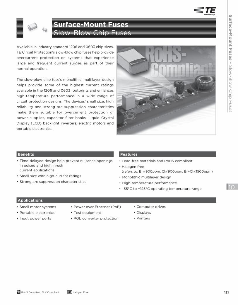
Available in industry standard 1206 and 0603 chip sizes,
TE Circuit Protection’s slow-blow chip fuses help provide
overcurrent protection on systems that experience
large and frequent current surges as part of their
normal operation.
The slow-blow chip fuse’s monolithic, multilayer design
helps provide some of the highest current ratings
available in the 1206 and 0603 footprints and enhances
high-temperature performance in a wide range of
circuit protection designs. The devices’ small size, high
reliability and strong arc suppression characteristics
make them suitable for overcurrent protection of
power supplies, capacitor filter banks, Liquid Crystal
Display (LCD) backlight inverters, electric motors and
portable electronics.
• Time-delayed design help prevent nuisance openings
in pulsed and high inrush
current applications
• Small size with high-current ratings
• Strong arc suppression characteristics
• Lead-free materials and RoHS compliant
• Halogen free
(refers to: Br#900ppm, Cl#900ppm, Br+Cl#1500ppm)
• Monolithic multilayer design
• High-temperature performance
• -55°C to +125°C operating temperature range
• Small motor systems
• Portable electronics
• Input power ports
Benefits Features
Applications
• Power over Ethernet (PoE)
• Test equipment
• POL converter protection
• Computer drives
• Displays
• Printers
Surface-Mount FusesSlow-Blow Chip Fuses
2013_CP_S10-Fuses-6-FS-SlowBlow.indd 121 9/11/13 2:00 PM
RoHS Compliant, ELV Compliant HF Halogen Free122
10
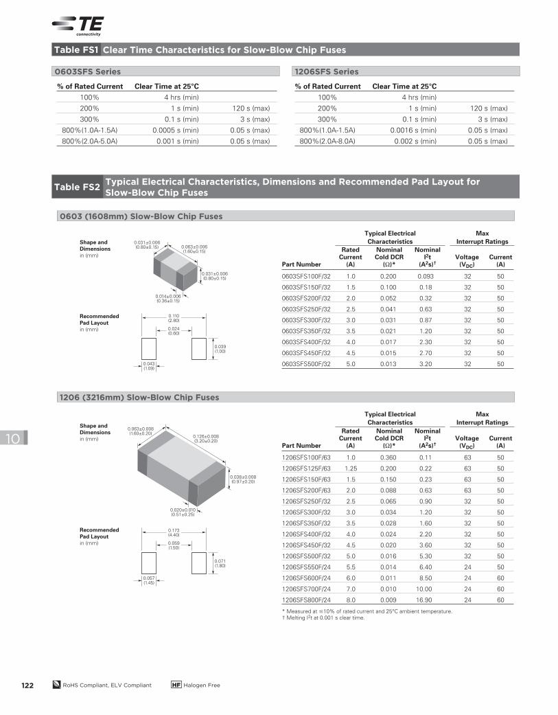
% of Rated Current Clear Time at 25°C
100% 4 hrs (min)
200% 1 s (min) 120 s (max)
300% 0.1 s (min) 3 s (max)
800%(1.0A-1.5A) 0.0005 s (min) 0.05 s (max)
800%(2.0A-5.0A) 0.001 s (min) 0.05 s (max)
% of Rated Current Clear Time at 25°C
100% 4 hrs (min)
200% 1 s (min) 120 s (max)
300% 0.1 s (min) 3 s (max)
800%(1.0A-1.5A) 0.0016 s (min) 0.05 s (max)
800%(2.0A-8.0A) 0.002 s (min) 0.05 s (max)
0603SFS Series 1206SFS Series
1206SFS100F/63 1.0 0.360 0.11 63 50
1206SFS125F/63 1.25 0.200 0.22 63 50
1206SFS150F/63 1.5 0.150 0.23 63 50
1206SFS200F/63 2.0 0.088 0.63 63 50
1206SFS250F/32 2.5 0.065 0.90 32 50
1206SFS300F/32 3.0 0.034 1.20 32 50
1206SFS350F/32 3.5 0.028 1.60 32 50
1206SFS400F/32 4.0 0.024 2.20 32 50
1206SFS450F/32 4.5 0.020 3.60 32 50
1206SFS500F/32 5.0 0.016 5.30 32 50
1206SFS550F/24 5.5 0.014 6.40 24 50
1206SFS600F/24 6.0 0.011 8.50 24 60
1206SFS700F/24 7.0 0.010 10.00 24 60
1206SFS800F/24 8.0 0.009 16.90 24 60
* Measured at #10% of rated current and 25°C ambient temperature.
† Melting I2t at 0.001 s clear time.
Part Number
RatedCurrent
(A)
NominalCold DCR
(Ω)*Voltage
(VDC)Current
(A)
1206 (3216mm) Slow-Blow Chip Fuses
0603 (1608mm) Slow-Blow Chip Fuses
Shape andDimensionsin (mm)
RecommendedPad Layoutin (mm)
0.063±0.008(1.60±0.20)
0.126±0.008(3.20±0.20)
0.038±0.008(0.97±0.20)
0.020±0.010(0.51±0.25)
0.173(4.40)
0.071(1.80)
0.057(1.45)
0.059(1.50)
NominalI2t
(A2s)†
0603SFS100F/32 1.0 0.200 0.093 32 50
0603SFS150F/32 1.5 0.100 0.18 32 50
0603SFS200F/32 2.0 0.052 0.32 32 50
0603SFS250F/32 2.5 0.041 0.63 32 50
0603SFS300F/32 3.0 0.031 0.87 32 50
0603SFS350F/32 3.5 0.021 1.20 32 50
0603SFS400F/32 4.0 0.017 2.30 32 50
0603SFS450F/32 4.5 0.015 2.70 32 50
0603SFS500F/32 5.0 0.013 3.20 32 50
Part Number
RatedCurrent
(A)
NominalCold DCR
(Ω)*Voltage
(VDC)Current
(A)
NominalI2t
(A2s)†
Shape andDimensionsin (mm)
RecommendedPad Layoutin (mm)
0.031±0.006(0.80±0.15)
0.031±0.006(0.80±0.15)
0.014±0.006(0.36±0.15)
0.063±0.006(1.60±0.15)
0.110(2.80)
0.039(1.00)
0.043(1.09)
0.024(0.60)
Typical Electrical
Characteristics
Max
Interrupt Ratings
Typical Electrical
Characteristics
Max
Interrupt Ratings
Table FS1 Clear Time Characteristics for Slow-Blow Chip Fuses
Table FS2Typical Electrical Characteristics, Dimensions and Recommended Pad Layout for
Slow-Blow Chip Fuses
2013_CP_S10-Fuses-6-FS-SlowBlow.indd 122 8/3/13 11:00 AM
Su
rface
-Mo
un
t Fu
se
s –
Slo
w-B
low
Ch
ip F
uses
RoHS Compliant, ELV Compliant HF Halogen Free 123
10
Cle
ar T
ime (
s)
100
10
1
0.1
0.01
0.001
10 1001
Current (A)
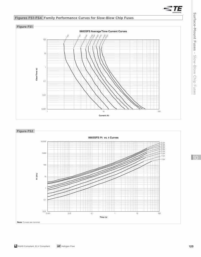
0603SFS Average Time Current Curves
1.0A
1.5A
2.0
A
2.5
A3.0
A
3.5
A4.0
A
4.5
A5.0
A
Figure FS1
I2t
(A2s)
10,000
1000
100
10
1
0.1
0.010.001 0.01 100.1 1 100
Time (s)
0603SFS I²t vs. t Curves
1.0A
1.5A
2.0A
2.5A3.0A3.5A4.0A4.5A5.0A
Figure FS2
Note: Curves are nominal.
Figures FS1-FS4 Family Performance Curves for Slow-Blow Chip Fuses
2013_CP_S10-Fuses-6-FS-SlowBlow.indd 123 8/3/13 11:00 AM
RoHS Compliant, ELV Compliant HF Halogen Free124
10
Cle
ar T
ime (
s)
100
10
1
0.1
0.01
0.001
10 100 10001
Current (A)
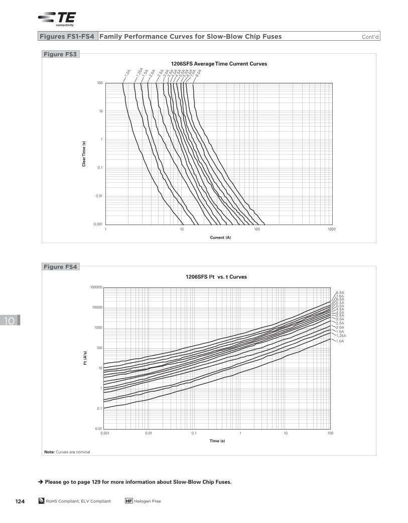
1206SFS Average Time Current Curves
1.0A
1.25A
1.5A
2.0
A
2.5
A3.0
A3.5
A4.0
A4.5
A5.0
A5.5
A6.0
A7.
0A
8.0
A
Figure FS3
I2t
(A2s)
100000
10000
1000
100
10
1
0.1
0.01
0.001 0.01 100.1 1 100
Time (s)
1206SFS I²t vs. t Curves
1.0A
1.5A
2.5A3.0A3.5A4.0A4.5A5.0A5.5A6.0A7.0A8.0A
2.0A
1.25A
Figure FS4
Note: Curves are nominal
Figures FS1-FS4 Family Performance Curves for Slow-Blow Chip Fuses Cont’d
Please go to page 129 for more information about Slow-Blow Chip Fuses.
2013_CP_S10-Fuses-6-FS-SlowBlow.indd 124 8/3/13 11:00 AM
Su
rface
-Mo
un
t Fu
se
s –
24
10 V
ery
Fast-A
ctin
g F
uses
RoHS Compliant, ELV Compliant HF Halogen Free 125
10
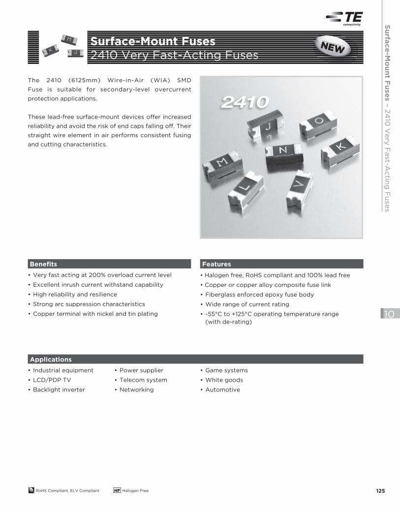
The 2410 (6125mm) Wire-in-Air (WIA) SMD
Fuse is suitable for secondary-level overcurrent
protection applications.
These lead-free surface-mount devices offer increased
reliability and avoid the risk of end caps falling off. Their
straight wire element in air performs consistent fusing
and cutting characteristics.
• Very fast acting at 200% overload current level
• Excellent inrush current withstand capability
• High reliability and resilience
• Strong arc suppression characteristics
• Copper terminal with nickel and tin plating
• Halogen free, RoHS compliant and 100% lead free
• Copper or copper alloy composite fuse link
• Fiberglass enforced epoxy fuse body
• Wide range of current rating
• -55°C to +125°C operating temperature range
(with de-rating)
• Industrial equipment
• LCD/PDP TV
• Backlight inverter
Benefits Features
Applications
• Power supplier
• Telecom system
• Networking
• Game systems
• White goods
• Automotive
Surface-Mount Fuses
2410 Very Fast-Acting FusesNEWNENENENEWWWWNEW
2013_CP_S10-Fuses-7-FV-2410-Very-Fast-Acting.indd 125 8/3/13 11:00 AM

RoHS Compliant, ELV Compliant HF Halogen Free126
10
% of Rated Current Clear Time at 25°C
100% 4 hrs (min)
200% (0.5A-10.0A) 0.01 s (min) 5 s (max)
200% (12.0A-20.0A) 0.01 s (min) 20 s (max)
2410 (6125mm) Very Fast-Acting Fuse
Shape and Dimensions
mm (in)
D
AC
B
Table SFV1 Clear Time Characteristics for 2410 Very Fast-Acting Fuses
Table SFV2Typical Electrical Characteristics, Dimensions and Recommended Pad Layout for 2410 Very Fast-Acting Fuses
Recommended Pad Layout
mm (Inch)
8.60(0.338)
2.80(0.110)
3.00(0.118)
A B C D
Min Max Min Max Min Max Min Max
mm 5.95 6.25 1.96 2.36 0.97 1.73 2.34 2.64
in (0.234) (0.246) (0.077) (0.093) (0.038) (0.068) (0.092) (0.104)
Part NumberMarking
CodeRated
Current (A)Interrupt Rating
Voltage Rating (V) Nominal Cold DC
Resistance (DCR) (Ω)*
Nominal I2t (A2s)AC DC
2410SFV0.50FM/125 C 0.5
UL:
0.5~2A
100A @ 250VAC
2.5~8A
50A @ 125VAC
0.5~8A
50A @ 125VDC
300A @ 32VDC
TUV:
0.5~2A
100A @ 250VAC
50A @ 125VDC
CQC:
0.5A, 1A, 2A
100A @ 250VAC
50A @ 125VDC
250 125 0.231 0.1
2410SFV0.63FM/125 S 0.63 250 125 0.174 0.16
2410SFV0.75FM/125 D 0.75 250 125 0.148 0.23
2410SFV1.00FM/125 E 1 250 125 0.093 0.59
2410SFV1.25FM/125 F 1.25 250 125 0.07 0.96
2410SFV1.50FM/125 G 1.5 250 125 0.062 1.19
2410SFV2.00FM/125 I 2 250 125 0.042 2.75
2410SFV2.50FM/125 J 2.5 125 125 0.031 1.21
2410SFV3.00FM/125 K 3 125 125 0.0249 1.73
2410SFV3.15FM/125 V 3.15 125 125 0.0232 2.2
2410SFV3.50FM/125 L 3.5 125 125 0.022 2.5
2410SFV4.00FM/125 M 4 125 125 0.0172 4.1
2410SFV5.00FM/125 N 5 125 125 0.0143 5.9
2410SFV6.30FM/125 O 6.3 125 125 0.01 12.5
2410SFV7.00FM/125 P 7 125 125 0.0094 14.2
2410SFV8.00FM/125 R 8 125 125 0.0086 20.3
2410SFV10.0FM/125 Q 10
UL:
35A @ 125VAC
50A @ 125VDC
300A @ 32VDC
125 125 0.0066 29.2
2410SFV12.0FM/065 X 12UL:
50A @ 65VAC
50A @ 65VDC
300A @ 32VDC
65 65 0.0053 49.2
2410SFV15.0FM/065 Y 15 65 65 0.0038 102.5
2410SFV20.0FM/065 Z 20
UL:
50A @ 65VAC
100A @ 65VDC
300A @ 32VDC
65 65 0.0034 126.2
* Measured at ≤10% of rated current and 25°C ambient
2013_CP_S10-Fuses-7-FV-2410-Very-Fast-Acting.indd 126 9/5/13 9:07 AM
Su
rface
-Mo
un
t Fu
se
s –
24
10 V
ery
Fast-A
ctin
g F
uses
RoHS Compliant, ELV Compliant HF Halogen Free 127
10
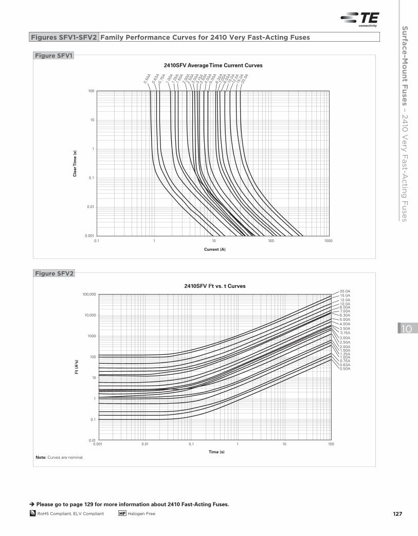
Please go to page 129 for more information about 2410 Fast-Acting Fuses.
Cle
ar T
ime (
s)
100
10
1
0.1
0.01
0.001
10 100010010.1
Current (A)
2410SFV Average Time Current Curves
0.6
3A
0.5
0A
0.7
5A
1.00A
1.25A
1.50A
2.0
0A
2.5
0A
3.0
0A
3.1
5A
3.5
0A
4.0
0A
5.0
0A
6.3
0A
7.00A
8.0
0A
10.0
A12
.0A
15.0
A20.0
A
Figure SFV1
I2t
(A2s)
100,000
10,000
1000
100
10
1
0.1
0.010.010.001 100.1 1 100
Time (s)
2410SFV I2t vs. t Curves
1.00A
0.50A0.63A0.75A
1.50A1.25A
2.00A
2.50A
3.00A
3.15A3.50A
4.00A
5.00A
7.00A8.00A10.0A12.0A
15.0A20.0A
6.30A
Figure SFV2
Figures SFV1-SFV2 Family Performance Curves for 2410 Very Fast-Acting Fuses
Note: Curves are nominal.
2013_CP_S10-Fuses-7-FV-2410-Very-Fast-Acting.indd 127 8/3/13 11:00 AM

RoHS Compliant, ELV Compliant HF Halogen Free128
10
2013_CP_S10-Fuses-7-FV-2410-Very-Fast-Acting.indd 128 8/3/13 11:00 AM
Su
rface
-Mo
un
t Fu
se
s - S
pecifi
catio
ns fo
r All F
uses
RoHS Compliant, ELV Compliant HF Halogen Free 129
10
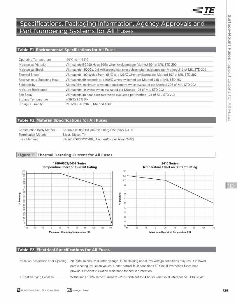
Specifications, Packaging Information, Agency Approvals and Part Numbering Systems for All Fuses
Operating Temperature -55°C to +125°C
Mechanical Vibration Withstands 5-3000 Hz at 30Gs when evaluated per Method 204 of MIL-STD-202
Mechanical Shock Withstands 1500Gs, 0.5 millisecond half-sine pulses when evaluated per Method 213 of MIL-STD-202
Thermal Shock Withstands 100 cycles from -65°C to +125°C when evaluated per Method 107 of MIL-STD-202
Resistance to Soldering Heat Withstands 60 seconds at +260°C when evaluated per Method 210 of MIL-STD-202
Solderability Meets 95% minimum coverage requirement when evaluated per Method 208 of MIL-STD-202
Moisture Resistance Withstands 10 cycles when evaluated per Method 106 of MIL-STD-202
Salt Spray Withstands 48-hour exposure when evaluated per Method 101 of MIL-STD-202
Storage Temperature #30°C/ 85% RH
Storage Humidity Per MIL-STD-202F, Method 106F
Construction Body Material Ceramic (1206/0603/0402); Fiberglass/Epoxy (2410)
Termination Material Silver, Nickel, Tin
Fuse Element Silver(1206/0603/0402); Copper/Copper Alloy (2410)
1206/0603/0402 SeriesTemperature Effect on Current Rating
2410 SeriesTemperature Effect on Current Rating
% D
era
tin
g
% D
era
tin
g
105
100
95
90
85
80
75
70
65
60
55
50
45
40
35
30
25
20
15
10
5
0
110
105
100
95
90
85
80
75
70
65
60
55
50
Maximum Operating Temperature (˚C) Maximum Operating Temperature (˚C)
-55 -35 -15 5 25 45 65 85 105 125 145 -55 -35 -15 5 25 45 65 85 105 125
Insulation Resistance after Opening 20,000Ω minimum @ rated voltage. Fuse clearing under low-voltage conditions may result in lower
post-clearing insulation values. Under normal fault conditions TE Circuit Protection fuses help
provide sufficient insulation resistance for circuit protection.
Current Carrying Capacity Withstands 100% rated current at +25°C ambient for 4 hours when evaluated per MIL-PRF-23419.
Table F1 Environmental Specifications for All Fuses
Table F2 Material Specifications for All Fuses
Figure F1 Thermal Derating Current for All Fuses
Table F3 Electrical Specifications for All Fuses
2013_CP_S10-Fuses-8-General.indd 129 8/3/13 11:00 AM
RoHS Compliant, ELV Compliant HF Halogen Free130
10
Recommended Conditions for Hand Soldering:
1. Using a hot air rework station that can reflow the solder on both terminations at the same time is strongly
recommended; do not directly contact the chip termination with the tip of soldering iron.
2. Preheating: 150°C, 60s (min)
Appropriate temperature (max) of soldering iron tip/soldering time (max): 280°C /10s or 350°C /3s.
0402 (1005) 10,000 178mm White Plastic 9.0 ± 0.5mm 8.00 ± 0.10mm Paper 5 1 to 10
0603 (1608) 4,000 178mm White Plastic 9.0 ± 0.5mm 8.00 ± 0.10mm Paper 5 1 to 10
0603SFV (1608) 6,000 178mm White Plastic 9.0 ± 0.5mm 8.00 ± 0.10mm Paper 5 1 to 10
1206 (3216) 3,000 178mm White Plastic 9.0 ± 0.5mm 8.00 ± 0.10mm Plastic 5 1 to 10
2410 (6125) 2,000 178mm White Plastic 13.4 ± 0.5mm 12.00 ± 0.10mm Plastic 4 1 to 10
SizeReel Quantity
(pcs) Reel Diameter Reel WidthCarrier
Tape Size Tape TypeReels per Outside
Shipment BoxOutside Shipment
Boxes per Overpack
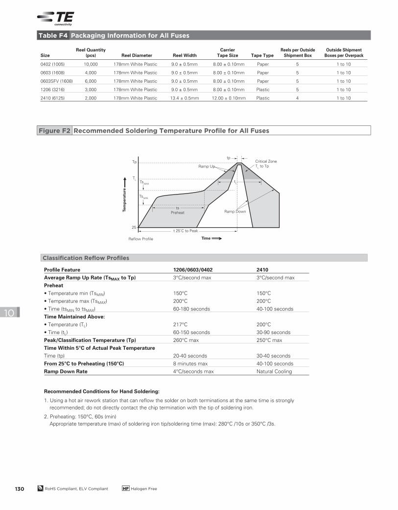
Table F4 Packaging Information for All Fuses
Figure F2 Recommended Soldering Temperature Profile for All Fuses
Profile Feature 1206/0603/0402 2410
Average Ramp Up Rate (TsMAX to Tp) 3°C/second max 3°C/second max
Preheat
• Temperature min (TsMIN) 150°C 150°C
• Temperature max (TsMAX) 200°C 200°C
• Time (tsMIN to tsMAX) 60-180 seconds 40-100 seconds
Time Maintained Above:
• Temperature (TL) 217°C 200°C
• Time (tL) 60-150 seconds 30-90 seconds
Peak/Classification Temperature (Tp) 260°C max 250°C max
Time Within 5°C of Actual Peak Temperature
Time (tp) 20-40 seconds 30-40 seconds
From 25°C to Preheating (150°C) 8 minutes max 40-100 seconds
Ramp Down Rate 4°C/seconds max Natural Cooling
Critical Zone
TL to TpRamp Up
t 25˚C to Peak
Reflow Profile Time
Ramp Downts
Preheat
TsMAX
TL
Tptp
25
TsMIN
tL
Tem
pera
ture
Classification Reflow Profiles
2013_CP_S10-Fuses-8-General.indd 130 8/3/13 11:00 AM
Su
rface
-Mo
un
t Fu
se
s - S
pecifi
catio
ns fo
r All F
uses
RoHS Compliant, ELV Compliant HF Halogen Free 131
10P
0
P0
P2
P1
P1
E1
E1
F
F
W
W
t
D0
D0
D1
D1
A0
A0
B0
K0
K0
B0
P2
Paper Carrier Tape Specifications
Plastic Carrier Tape Specifications
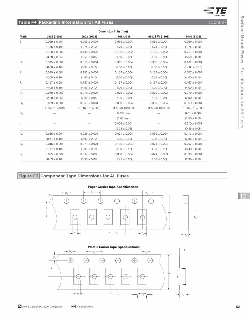
Figure F3 Component Tape Dimensions for All Fuses
Dimension in in (mm)
Mark 0402 (1005) 0603 (1608) 1206 (3216) 0603SFV (1608) 2410 (6125)
E1 0.069 ± 0.004 0.069 ± 0.004 0.069 ± 0.004 0.069 ± 0.004 0.069 ± 0.004
(1.75 ± 0.10) (1.75 ± 0.10) (1.75 ± 0.10) (1.75 ± 0.10) (1.75 ± 0.10)
F 0.138 ± 0.002 0.138 ± 0.002 0.138 ± 0.002 0.138 ± 0.002 0.217 ± 0.004
(3.50 ± 0.05) (3.50 ± 0.05) (3.50 ± 0.05) (3.50 ± 0.05) (5.50 ± 0.10)
W 0.315 ± 0.004 0.315 ± 0.004 0.315 ± 0.004 0.315 ± 0.004 0.472 ± 0.004
(8.00 ± 0.10) (8.00 ± 0.10) (8.00 ± 0.10) (8.00 ± 0.10) (12.00 ± 0.10)
P1 0.079 ± 0.004 0.157 ± 0.004 0.157 ± 0.004 0.157 ± 0.004 0.157 ± 0.004
(2.00 ± 0.10) (4.00 ± 0.10) (4.00 ± 0.10) (4.00 ± 0.10) (4.00 ± 0.10)
P0 0.157 ± 0.004 0.157 ± 0.004 0.157 ± 0.004 0.157 ± 0.004 0.157 ± 0.004
(4.00 ± 0.10) (4.00 ± 0.10) (4.00 ± 0.10) (4.00 ± 0.10) (4.00 ± 0.10)
P2 0.079 ± 0.002 0.079 ± 0.002 0.079 ± 0.002 0.079 ± 0.002 0.079 ± 0.004
(2.00 ± 0.05) (2.00 ± 0.05) (2.00 ± 0.05) (2.00 ± 0.05) (2.00 ± 0.10)
D0 0.059 ± 0.004 0.059 ± 0.004 0.059 ± 0.004 0.059 ± 0.004 0.059 ± 0.004
(1.50+0.10/-0.00) (1.50+0.10/-0.00) (1.50+0.10/-0.00) (1.50+0.10/-0.00) (1.50+0.10/-0.00)
D1 — — 0.039 max — 0.61 ± 0.004
(1.00 max) (1.55 ± 0.10)
t — — 0.009 ± 0.001 — 0.010 ± 0.002
(0.23 ± 0.02) (0.25 ± 0.05)
A0 0.026 ± 0.004 0.039 ± 0.004 0.071 ± 0.004 0.039 ± 0.004 0.112 ± 0.004
(0.67 ± 0.10) (0.98 ± 0.10) (1.80 ± 0.10) (0.98 ± 0.10) (2.85 ± 0.10)
B0 0.046 ± 0.004 0.071 ± 0.004 0.138 ± 0.004 0.071 ± 0.004 0.252 ± 0.004
(1.17 ± 0.10) (1.80 ± 0.10) (3.50 ± 0.10) (1.80 ± 0.10) (6.40 ± 0.10)
K0 0.025 ± 0.004 0.037 ± 0.003 0.050 ± 0.004 0.024 ± 0.003 0.093 ± 0.004
(0.63 ± 0.10) (0.95 ± 0.08) (1.27 ± 0.10) (0.60 ± 0.08) (2.35 ± 0.10)
Table F4 Packaging Information for All Fuses (Cont’d)
2013_CP_S10-Fuses-8-General.indd 131 8/3/13 11:00 AM
RoHS Compliant, ELV Compliant HF Halogen Free132
10
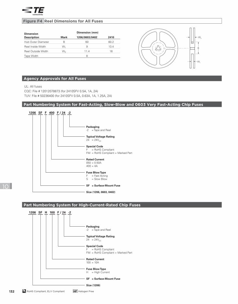
Dimension
Description Mark 1206/0603/0402 2410
Hub Outer Diameter B 60 60.2
Reel Inside Width W1 9 13.4
Reel Outside Width W2 11.4 16
Tape Width 8
B
W2
W1
Figure F4 Reel Dimensions for All Fuses
Agency Approvals for All Fuses
UL: All fuses
CQC: File # 12012078873 (for 2410SFV 0.5A, 1A, 2A)
TUV: File # 50236400 (for 2410SFV 0.5A, 0.63A, 1A, 1.25A, 2A)
Part Numbering System for Fast-Acting, Slow-Blow and 0603 Very Fast-Acting Chip Fuses
1206 SF F 400 F / 24 -2
Packaging-2 = Tape and Reel
Typical Voltage Rating24 = 24V
DC
Special CodeF = RoHS Compliant
FM = RoHS Compliant + Marked Part
Rated Current050 = 0.50A
400 = 4A
Fuse Blow TypeF = Fast Acting
S = Slow Blow
SF = Surface-Mount Fuse
Size (1206, 0603, 0402)
Part Numbering System for High-Current-Rated Chip Fuses
1206 SF H 100 F / 24 -2
Packaging-2 = Tape and Reel
Typical Voltage Rating24 = 24V
DC
Special CodeF = RoHS Compliant
FM = RoHS Compliant + Marked Part
Rated Current100 = 10A
Fuse Blow TypeH = High Current
SF = Surface-Mount Fuse
Size (1206)
Dimension (mm)
2013_CP_S10-Fuses-8-General.indd 132 8/3/13 11:00 AM
Su
rface
-Mo
un
t Fu
se
s - S
pecifi
catio
ns fo
r All F
uses
RoHS Compliant, ELV Compliant HF Halogen Free 133
10
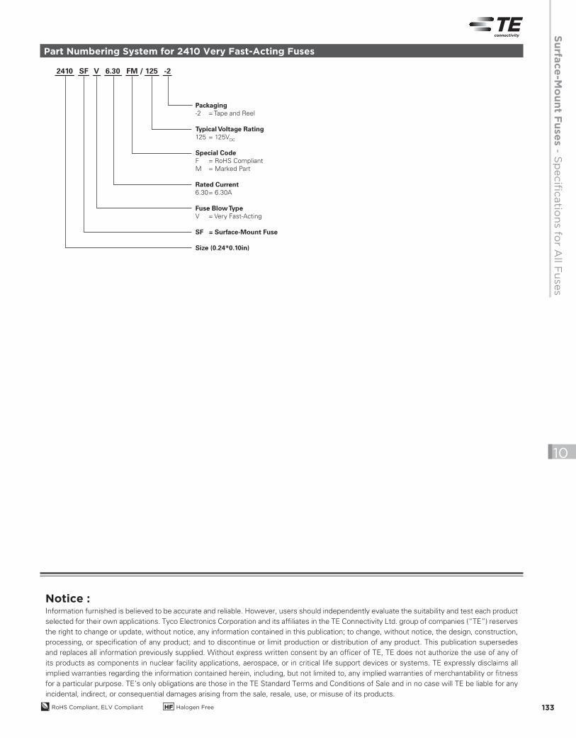
Part Numbering System for 2410 Very Fast-Acting Fuses
2410 SF V 6.30 FM / 125 -2
Packaging-2 = Tape and Reel
Typical Voltage Rating125 = 125V
DC
Special CodeF = RoHS Compliant
M = Marked Part
Rated Current6.30 = 6.30A
Fuse Blow TypeV = Very Fast-Acting
SF = Surface-Mount Fuse
Size (0.24*0.10in)
Notice :Information furnished is believed to be accurate and reliable. However, users should independently evaluate the suitability and test each product
selected for their own applications. Tyco Electronics Corporation and its affiliates in the TE Connectivity Ltd. group of companies (“TE”) reserves
the right to change or update, without notice, any information contained in this publication; to change, without notice, the design, construction,
processing, or specification of any product; and to discontinue or limit production or distribution of any product. This publication supersedes
and replaces all information previously supplied. Without express written consent by an officer of TE, TE does not authorize the use of any of
its products as components in nuclear facility applications, aerospace, or in critical life support devices or systems. TE expressly disclaims all
implied warranties regarding the information contained herein, including, but not limited to, any implied warranties of merchantability or fitness
for a particular purpose. TE’s only obligations are those in the TE Standard Terms and Conditions of Sale and in no case will TE be liable for any
incidental, indirect, or consequential damages arising from the sale, resale, use, or misuse of its products.
2013_CP_S10-Fuses-8-General.indd 133 8/3/13 11:00 AM