Embed Size (px)
Citation preview
Unit
Second
Surface Finishing Prof. Shashank S. Bhamble
Mechanical Engineering Department
Shri Sant Gajanan Maharaj College of Engineering, Shegaon
Advanced Manufacturing Techniques
Page | 1
HONING (METALWORKING)
Honing is a manufacturing process that produces a precision surface on a workpiece by scrubbing
an abrasive stone against it along a controlled path. Honing is primarily used to improve the
geometric form of a surface, but may also improve surface texture.
Honing stones
Honing is classified as an abrasive machining manufacturing process. As with all abrasive
machining processes, material is cut away from the workpiece using abrasive grains. In the case of
honing, the grains are bound together with an adhesive to form a honing stone (or hone). Generally,
honing grains are irregularly shaped and about 10 to 50 micrometers in diameter (300 to 1,500
mesh grit). Smaller grain sizes produce a smoother surface on the workpiece.
A honing stone is similar to a grinding wheel in many ways, but honing stones are usually more
friable so that they conform to the shape of the workpiece as they wear in. To counteract their
friability, honing stones may be treated with wax or sulfur to improve life; wax is usually preferred
for environmental reasons.[1]
Any abrasive material may be used to create a honing stone, but the most commonly used are
corundum, silicon carbide, CBN or diamond. The choice of abrasive material is usually driven by
the characteristics of the workpiece material. In most cases, corundum or silicon carbide are
acceptable, but extremely hard workpiece materials must be honed using superabrasives.
Process mechanics
Since honing stones look similar to grinding wheels, it is tempting to think of honing as a form of
low-stock removal grinding. Instead, it is better to think of it as a self-truing grinding process.
In grinding, the wheel follows a simple path. For example, in plunge grinding a shaft, the wheel
moves in towards the axis of the part, grinds it, and then moves back out. Since each slice of the
wheel repeatedly contacts the same slice of the workpiece, any inaccuracies in the geometric shape
of the grinding wheel will be transferred onto the part. Therefore, the accuracy of the finished
workpiece geometry is limited to the accuracy of the truing dresser. The accuracy becomes even
worse as the grind wheel wears, so truing must occur periodically to reshape it.
The limitation on geometric accuracy is overcome in honing because the honing stone follows a
complex path. In bore honing for example, the stone moves along two paths simultaneously. The
stones are pressed radially outward to enlarge the hole while they simultaneously oscillate axially.
Due to the oscillation, each slice of the honing stones touch a large area of the workpiece.
Therefore, imperfections in the honing stone's profile cannot transfer to the bore. Instead both the
bore and the honing stones conform to the average shape of the honing stones' motion, which in the
case of bore honing is a cylinder. This averaging effect occurs in all honing processes; both the
workpiece and stones erode until they conform to the average shape of the stones' cutting surface.
Since the honing stones tend to erode towards a desired geometric shape, there is no need to true
them. As a result of the averaging effect, the accuracy of a honed component often exceeds the
accuracy of the machine tool that created it.
The path of the stone is not the only difference between grinding and honing machines, they also
differ in the stiffness of their construction. Honing machines are much more compliant than
grinders. The purpose of grinding is to achieve a tight size tolerance. To do this, the grinding wheel
Advanced Manufacturing Techniques
Page | 2
must be moved to an exact position relative to the workpiece. Therefore a grinding machine must
be very stiff and its axes must move with very high precision.
A honing machine, ironically, is relatively inaccurate and compliant. Instead of relying on the
accuracy of the machine tool, it relies on the averaging effect between the stone and the workpiece.
In fact, compliance is a requirement of a honing machine that is necessary for the averaging effect
to occur. This leads to an obvious difference between the two machines: in a grinder the stone is
rigidly attached to a slide, while in honing the stone is actuated with pneumatic or hydraulic
pressure.
High-precision workpieces are usually ground and then honed. Grinding determines the size, and
honing improves the shape.
The difference between honing and grinding is not always distinct. Some grinders have complex
movements and are self-truing, and some honing machines are equipped with in-process gaging for
size control. Many through-feed grinding operations rely on the same averaging effect as honing.
Honing configurations
Track/Raceway honing
Spherical honing
OD through-feed honing (taper and straight)
Flat honing
Bore honing
Comparisons to grinding
Superfinishing is more expensive than grinding. Superfinishing has lower cutting efficiency
because of smaller chips. Superfinishing has lower material removal rate. Superfinishing stones are
softer and wear more quickly. Superfinishing stones don't need to be dressed. A superfinishing
machine must move the stone in a compound or orbital motion relative to the part surface. In
honing, the contact area between the abrasive and workpiece are larger than in grinding.[3]
Unlike polishing, superfinishing can improve the geometric form of an object. The primary purpose
of polishing is to improve surface finish without concern for form.
Economics
Since honing is a high precision process, it is also relatively expensive. Therefore it is only used in
components that demand the highest level of precision. It is typically the last manufacturing
operation before the part is shipped to a customer. The dimensional size of the object is established
by preceding operations, the last of which is usually grinding. Then the part is honed to improve a
form characteristic such as roundness, flatness, cylindricity, or sphericity.
Performance advantages of honed surfaces
Since honing is a relatively expensive manufacturing process, it can only be economically justified
for applications that require very good form accuracy. The improved shape after honing may result
in a quieter running or higher precision component.
Advanced Manufacturing Techniques
Page | 3
LAPPING
Lapping is a machining operation, in which two surfaces are rubbed together with an abrasive
between them, by hand movement or by way of a machine.
This can take two forms. The first type of lapping (traditionally called grinding), typically involves
rubbing a brittle material such as glass against a surface such as iron or glass itself (also known as
the "lap" or grinding tool) with an abrasive such as aluminum oxide, emery, silicon carbide,
diamond, etc., in between them. This produces microscopic conchoidal fractures as the abrasive
rolls about between the two surfaces and removes material from both.
The other form of lapping involves a softer material for the lap, which is "charged" with the
abrasive. The lap is then used to cut a harder material—the workpiece. The abrasive embeds within
the softer material which holds it and permits it to score across and cut the harder material. Taken
to the finer limit, this will produce a polished surface such as with a polishing cloth on an
automobile, or a polishing cloth or polishing pitch upon glass or steel.
Taken to the ultimate limit, with the aid of accurate interferometry and specialized polishing
machines or skilled hand polishing, lensmakers can produce surfaces that are flat to better than 30
nanometers. This is one twentieth of the wavelength of light from the commonly used 632.8 nm
helium neon laser light source. Surfaces this flat can be molecularly bonded (optically contacted)
by bringing them together under the right conditions. (This is not the same as the wringing effect of
Johansson blocks, although it is similar).
Operation
By way of example, a piece of lead may be used as the lap, charged with emery, and used to cut a
piece of hardened steel. The small plate shown in the first picture is that of a hand lapping plate.
That particular plate is made of cast iron. In use, a slurry of emery powder would be spread on the
plate and the workpiece simply rubbed against the plate, usually in a "figure-eight" pattern.
The second picture is that of a commercially available lapping machine which is needed for this
process. The lap or lapping plate in this machine is 30 cm (12") in diameter. For a commercial
machine that is about the smallest size available. At the other end of the size spectrum, machines
with eight to ten foot diameter plates are not uncommon and systems with tables 30 feet in diameter
have been constructed. Referring to the second picture again, the lap is the large circular disk on the
top of the machine. On top of the lap are two rings. The workpiece would be placed inside one of
these rings. A weight would then be placed on top of the workpiece. The weights can also be seen
in the picture along with two fiber spacer disks that are just used to even the load.
In operation, the rings stay in one location as the lapping plate rotates beneath them. In this
machine, a small slurry pump can be seen at the side, this pump feeds abrasive slurry onto the
rotating lapping plate.
When there is a requirement to lap very small specimens (from 3" down to a few millimetres), a
lapping jig can be used to hold the material while it is lapped (see Image 3, lapping machine and
jig). A jig allows precise control of the orientation of the specimen to the lapping plate and fine
adjustment of the load applied to the specimen during the material removal process. Due to the
dimensions of such small samples, traditional loads and weights are too heavy as they would
destroy delicate materials. The jig sits in a cradle on top of the lapping plate and the dial on the
front of the jig indicates the amount of material removed from the specimen.
Advanced Manufacturing Techniques
Page | 4
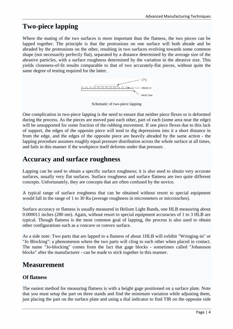
Two-piece lapping
Where the mating of the two surfaces is more important than the flatness, the two pieces can be
lapped together. The principle is that the protrusions on one surface will both abrade and be
abraded by the protrusions on the other, resulting in two surfaces evolving towards some common
shape (not necessarily perfectly flat), separated by a distance determined by the average size of the
abrasive particles, with a surface roughness determined by the variation in the abrasive size. This
yields closeness-of-fit results comparable to that of two accurately-flat pieces, without quite the
same degree of testing required for the latter.
Schematic of two-piece lapping
One complication in two-piece lapping is the need to ensure that neither piece flexes or is deformed
during the process. As the pieces are moved past each other, part of each (some area near the edge)
will be unsupported for some fraction of the rubbing movement. If one piece flexes due to this lack
of support, the edges of the opposite piece will tend to dig depressions into it a short distance in
from the edge, and the edges of the opposite piece are heavily abraded by the same action - the
lapping procedure assumes roughly equal pressure distribution across the whole surface at all times,
and fails in this manner if the workpiece itself deforms under that pressure.
Accuracy and surface roughness
Lapping can be used to obtain a specific surface roughness; it is also used to obtain very accurate
surfaces, usually very flat surfaces. Surface roughness and surface flatness are two quite different
concepts. Unfortunately, they are concepts that are often confused by the novice.
A typical range of surface roughness that can be obtained without resort to special equipment
would fall in the range of 1 to 30 Ra (average roughness in micrometers or microinches).
Surface accuracy or flatness is usually measured in Helium Light Bands, one HLB measuring about
0.000011 inches (280 nm). Again, without resort to special equipment accuracies of 1 to 3 HLB are
typical. Though flatness is the most common goal of lapping, the process is also used to obtain
other configurations such as a concave or convex surface.
As a side note: Two parts that are lapped to a flatness of about 1HLB will exhibit "Wringing-in" or
"Jo Blocking": a phenomenon where the two parts will cling to each other when placed in contact.
The name "Jo-blocking" comes from the fact that gage blocks - sometimes called "Johansson
blocks" after the manufacturer - can be made to stick together in this manner.
Measurement
Of flatness
The easiest method for measuring flatness is with a height gage positioned on a surface plate. Note
that you must setup the part on three stands and find the minimum variation while adjusting them,
just placing the part on the surface plate and using a dial indicator to find TIR on the opposite side
Advanced Manufacturing Techniques
Page | 5
of the part measures parallelism. Flatness is more easily measured with a co-ordinate measuring
machine. But neither of these methods can measure flatness more accurately than about 0.0001"
(2.5μm).
Another method that is commonly used with lapped parts is the reflection and interference of
monochromatic light.[1]
A monochromatic light source and an optical flat are all that are needed.
The optical flat – which is a piece of transparent glass that has itself been lapped and polished on
one or both sides – is placed on the lapped surface. The monochromatic light is then shone down
through the glass. The light will pass through the glass and reflect off the workpiece. As the light
reflects in the gap between the workpiece and the polished surface of the glass, the light will
interfere with itself creating light and dark fringes. Each fringe – or band – represents a change of
one half wavelength in the width of the gap between the glass and the workpiece. The light bands
display a contour map of the surface of the workpiece and can be readily interpreted for flatness. In
the past the light source would have been provided by a Helium lamp or tube, but nowadays a more
common source of monochromatic light is the low pressure sodium lamp. The picture to the right
shows a typical monochromatic light unit used in workshops and laboratories.
Of roughness
Surface roughness is defined by the minute variations in height of the surface of a given material or
workpiece. The individual variances of the peaks and valleys are averaged (Ra reading), or
quantified by the largest difference from peak-to-valley (Rz). Roughness is usually expressed in
microinches. A surface that exhibits an Ra of 8 consists of peaks and valleys that average no more
than 8 microinches over a given distance. Roughness may be also measured by comparing the
surface of the workpiece to a known sample. Calibration samples are available usually sold in a set
and usually covering the typical range of machining operations from about 125 Ra to 1 Ra.
Surface roughness is measured with a profilometer, an instrument that measures the minute
variations in height of the surface of a workpiece.
SUPERFINISHING
Superfinishing, also known as micromachining and short-stroke honing, is a metalworking
process that improves surface finish and workpiece geometry. This is achieved by removing just
the thin amorphous surface layer left by the last process with an abrasive stone; this layer is usually
about 1 μm in magnitude. Superfinishing, unlike polishing which produces a mirror finish, creates a
cross-hatch pattern on the workpiece.
The superfinishing process was developed by the Chrysler Corporation in 1934.
Process
After a metal piece is ground to an initial finish, it is superfinished with a finer grit solid abrasive.
The abrasive is oscillated or rotated while the workpiece is rotated in the opposite direction; these
motions are what causes the cross-hatching. The geometry of the abrasive depends on the geometry
of the workpiece surface; a stone (rectangular shape) is for cylindrical surfaces and cups and wheels
are used for flat and spherical surfaces. A lubricant is used to minimize heat production, which can
alter the metallurgical properties, and to carry away the swarf; kerosene is a common lubricant.
The abrasive cuts the surface of the workpiece in three phases. The first phase is when the abrasive
first contacts the workpiece surface the dull grains of the abrasive fracture and fall away, which
Advanced Manufacturing Techniques
Page | 6
produces a sharp new cutting surface. In the second phase the abrasive "self dresses", where a most
of the stock is removed. Finally, the abrasive grains dull, which improves the surface geometry.
The average rotational speed of abrasive wheel and/or workpiece is 1 to 15 surface m/min, with 6
to 14 m/min preferred; this is much slower compared to grinding speeds around 1800 to
3500 m/min. The pressure applied to the abrasive is very light, usually between 0.02 to 0.07 MPa
(3 to 10 psi), but can be as high as 2.06 MPa (299 psi). Honing is usually 3.4 to 6.9 MPa (490 to
1,000 psi) and grinding is between 13.7 to 137.3 MPa (1,990 to 19,910 psi). When a stone is used it
is oscillated at 200 to 1000 cycles with an amplitude of 1 to 5 mm (0.039 to 0.20 in).[3]
Superfinishing can give a surface finish of 0.01 μm.
Types There are three types superfinishing: Through-feed, plunge, and wheels.
Through-feed
This type of superfinishing is used for cylindrical workpieces. The workpiece is rotated
between two drive rollers, which also move the machine as well. Four to eight progressively
finer abrasive stones are used to superfinish the workpiece. The stones contact the
workpiece at a 90° angle and are oscillated axially. Examples of parts that would be
produced by process include tapered rolls, piston pins, shock absorber rods, shafts, and
needles.
Plunge
This type is used to finish irregularly shaped surfaces. The workpiece is rotated while the
abrasive plunges onto the desired surface.
Wheels
Abrasive cups or wheels are used to superfinish flat and spherical surfaces. The wheel and
workpiece are rotated in opposite directions, which creates the cross-hatching. If the two are
parallel then the result if a flat finish, but if the wheel is tilted slightly a convex or concave
surfaces will form.
Abrasives Common abrasives used for superfinishing include: aluminium oxide, silicon carbide, cubic boron
nitride (CBN), and diamond.
Aluminium oxide is used for "roughing" operations. Silicone carbide is harder than aluminium
oxide, so it is used for "finishing" operations. CBN and diamond are not as commonly used, but
find use with specialized materials, such as ceramics and M50. Note that graphite may be mixed
with other abrasives to add lubricity and to enhance the appearance of the finish.
Abrasive grains must be very fine to be used with superfinishing; usually 5–8 μm.
Advantages & disadvantages Advantages of superfinishing include: increasing part life, decreasing wear, closer tolerances,
higher load bearing surfaces, better sealing capabilities, and elimination of a break in period.
The main disadvantage is that superfinishing requires grinding or a hard turning operation
beforehand. This adds cost to the finished product.
Applications Common applications include: steering rack components, transmission components, fuel injector
components, camshaft lobes, hydraulic cylinder rods, bearing races, needle rollers, and sharpening
stones and wheels.
It has been proven that superfinishing certain parts makes them more durable. For example if the
teeth in a gear are superfinished they will last up to four times as long.
Advanced Manufacturing Techniques
Page | 7
BURNISH
Burnishing is a form of pottery treatment in which the surface of the pot is polished, using a hard
smooth surface such as a wooden or bone spatula, smooth stones, plastic, or even glass bulbs, while
it still is in a leathery 'green' state, i.e. before firing. After firing, the surface is extremely shiny.
Often the whole outer surface of the pot is thus decorated, but in certain ceramic traditions there is
'pattern burnishing' where the outside and, in the case of open bowls, the inside, are decorated with
burnished patterns in which some areas are left matte.
This technique can be applied to concrete masonry, creating a polished finish.
Burnishing can also be applied to wood. Hard woods are best to use with this. Rub them along one
another, the more important one should be rubbed down its grain, but cross ways will still work,
and shortly a glossy sheen will come up and the wood will become slick. Burnishing does not
protect the wood like a varnish does, but you do not have to wait for a burnished piece of wood to
dry as you would if you had varnished it.
If one wood has a dye in it, or is colored in some way, it may rub off onto the other wood, so
choose carefully and perform a test rub first. Burnishing can also apply to relief printing.
Burr (edge) A burr is a raised edge or small pieces of material remaining attached to a workpiece after a
modification process.[1]
It is usually an unwanted piece of material and when removed the process
is called deburring. Burrs are most commonly created after machining operations, such as
grinding, drilling, milling, engraving or turning. It may be present in the form of a fine wire on the
edge of a freshly sharpened tool or as a raised portion on a surface, after being struck a blow from
an equally hard, or heavy object.
Burr formation in machining accounts for a significant portion of machining costs for
manufacturers throughout the world. Drilling burrs, for example, are common when drilling almost
any material. The Boeing 747 airplane has approximately 1.3 million holes drilled in it, most of
which have to be deburred to some extent. As one could imagine, the cost and time needed to
perform these drilling and deburring operations is significant.
In addition to drilling, milling is also a source of burr formation in machining. One good example
of unwanted burrs is in the automotive industry where cylinder blocks, pistons and other engine
components are cast then milled to a specific dimension. With higher and higher demands placed
on accuracy and precision, burr formation is of critical importance because it can affect engine
performance, reliability, and durability. In the printmaking technique of drypoint, burr, which gives
a rich fuzzy quality to the engraved line, is highly desirable - the great problem with the drypoint
medium is that the burr rapidly diminishes after as few as ten impressions are printed.