Embed Size (px)
Citation preview
1
ThreeBond Technical News Issued July 1, 2006 67
Surface Crack Detection Coating Agent Introduction________________________________________________
The present state of the art for identifying surface cracks is less established than is generally believed. During on-site inspections, it is virtually impossible to detect surface cracks on the surfaces of components having complex shapes, such as weld areas. Given the constant possibility of overlooking surface cracks, a new method must be devised that can effectively assist unaided visual tests and improve detection rates.
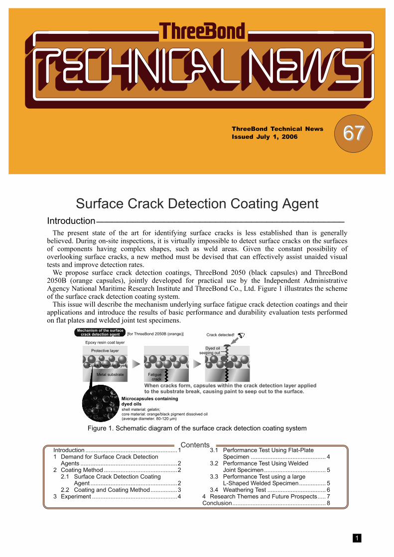
We propose surface crack detection coatings, ThreeBond 2050 (black capsules) and ThreeBond 2050B (orange capsules), jointly developed for practical use by the Independent Administrative Agency National Maritime Research Institute and ThreeBond Co., Ltd. Figure 1 illustrates the scheme of the surface crack detection coating system.
This issue will describe the mechanism underlying surface fatigue crack detection coatings and their applications and introduce the results of basic performance and durability evaluation tests performed on flat plates and welded joint test specimens.
shell material: gelatin; core material: orange/black pigment dissolved oil (average diameter: 80-120 μm)
Mechanism of the surface crack detection agent [for ThreeBond 2050B (orange)]
Epoxy resin coat layer
Microcapsules containing dyed oils
Fatigue crack
Crack detected!
Metal substrate
Protective layer Dyed oil seeping out
When cracks form, capsules within the crack detection layer applied to the substrate break, causing paint to seep out to the surface.
Crack detection layer
Figure 1. Schematic diagram of the surface crack detection coating system
Contents
Introduction .......................................................11 Demand for Surface Crack Detection
Agents ..........................................................2 2 Coating Method ............................................2
2.1 Surface Crack Detection Coating Agent ....................................................2
2.2 Coating and Coating Method................3 3 Experiment ...................................................4
3.1 Performance Test Using Flat-Plate Specimen ............................................. 4
3.2 Performance Test Using Welded Joint Specimen..................................... 5
3.3 Performance Test using a large L-Shaped Welded Specimen................ 5
3.4 Weathering Test ................................... 6 4 Research Themes and Future Prospects..... 7 Conclusion........................................................ 8
2
1 Demand for Surface Crack Detection Agents
Although several non-destructive testing methods have been proposed for identifying surface fatigue cracks in various structures including magnetic particle, penetrant, and eddy-current inspection methods, most approaches continue to rely on visual test. But the number of cracks that escape visual test is much greater than commonly thought, creating a demand for improved detection rates in visual tests.
Also needed is a test method that would enable inspectors to continuously and easily observe the crack growth to determine the appropriate time of repair work after crack detection. In addition, the method is rquired to veridate the repair work performed.
This issue presents a crack detection agent that meets these needs. Figure 2 illustrates its underlying mechanism.
Visual tests
crack- like forma- tion detected!
Full-fledged testing Magnetic particle inspection Eddy-current inspection Penetrant inspection
Left untreated:Observa- tion of status of growth
Facilitate verification by visual test
Verification of repair
Repair work Reinforcing plate Stop hole Gouging
Problem present!!
Difficulty in determining crack tip
Failure in detection
Enables easy observation of the status of crack growth.
Improved detection rates in visual tests
Difficult
Figure 2. Intended Use of Crack Detection Agent
In practice, detecting surface cracks that have formed on components with complex shapes such as welded joints is quite difficult. To give one example, such cracks are commonly encountered in hull inspections. Based on the results of a survey of maintenance and inspections of fatigue damage to bulk carriers, current test methods detect approximately 60% of existing cracks, rest of 40% unidentified. The results also indicate that approximately 30% of the surface cracks generated exceed 200 mm in length, while 10% grow to lengths exceeding 500 mm.1) One would expect similar crack detection failures in marine vessels other than bulk carriers, including crude oil carriers and passenger liners. So we should devise a new method that would provide effective assistance with on-site visual tests and improve detection rates.
In the 10 years subsequent to 1990, researchers at Lehigh University in the United States have studied crack detection technologies using a special coating agent called Smart Paint.2)
Smart Paint incorporates microcapsules containing pigments mixed into a normal epoxy
resin-based maintenance coating. When this coating is applied to a base metal, the formation and growth of cracks breaks the capsules, releasing the pigment and subsequently coloring the coating surface to facilitate detection of cracks. We have successfully developed just such a surface crack detection coating system and plan to market it as ThreeBond 2050 (black capsules) and ThreeBond 2050B (orange capsules), discussed in this issue.
Field tests on steel bridges and marine vessels were performed to validate the effectiveness of this coating, confirming coloring at the surface cracks.3)
Results from our laboratory experiment provided the effectiveness of the present surface crack detection coating. To verify the scope of applicability, we plan to perform testing to evaluate its conformity to actual structures.4)
2 Coating Method 2.1 Surface Crack Detection Coating Agent
The surface crack detection coatings, ThreeBond 2050 (black capsules) and ThreeBond 2050B (orange capsules), used in this study are epoxy resin-based anticorrosion coatings that incorporate pigment-filled microcapsules. The method for preparing the microcapsules, their coating characteristics, and coating procedures are described below.
2.1.1 Preparing the Microcapsules The core material is microfabricated by
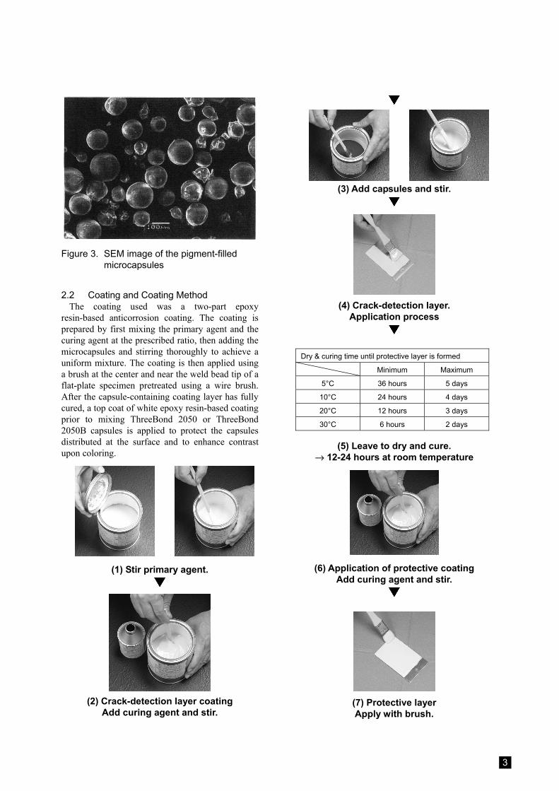
dissolving an orange organic pigment in spindle oil and encapsulating solution into the gelatin-forming shell material. The microcapsule is prepared by the coacervation method,5) then washed and dried. Figure 3 shows the finished microcapsule image observed by SEM (scanning electron microscope). Particle size distribution analysis shows average diameters of around 100 μm, with most particles plotting within the range of 80-120μm.
3
Figure 3. SEM image of the pigment-filled microcapsules
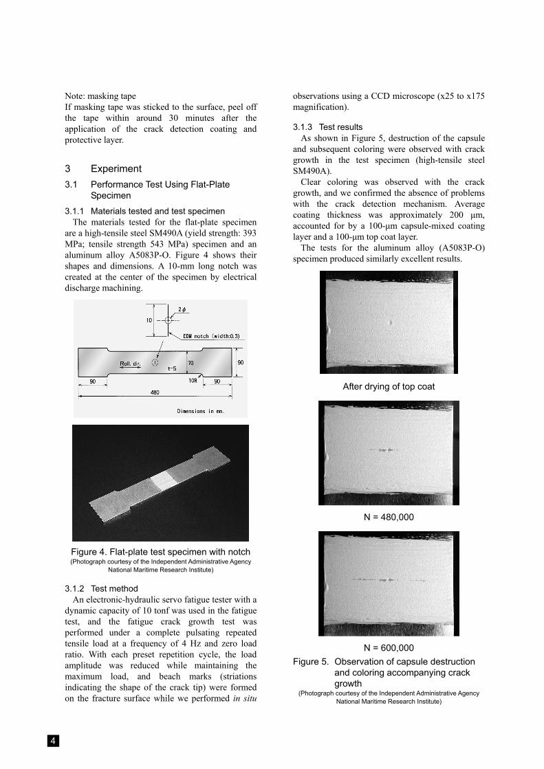
2.2 Coating and Coating Method The coating used was a two-part epoxy
resin-based anticorrosion coating. The coating is prepared by first mixing the primary agent and the curing agent at the prescribed ratio, then adding the microcapsules and stirring thoroughly to achieve a uniform mixture. The coating is then applied using a brush at the center and near the weld bead tip of a flat-plate specimen pretreated using a wire brush. After the capsule-containing coating layer has fully cured, a top coat of white epoxy resin-based coating prior to mixing ThreeBond 2050 or ThreeBond 2050B capsules is applied to protect the capsules distributed at the surface and to enhance contrast upon coloring.
(1) Stir primary agent.
(2) Crack-detection layer coating
Add curing agent and stir.
(3) Add capsules and stir.
(4) Crack-detection layer.
Application process
Dry & curing time until protective layer is formed
Minimum Maximum
5°C 36 hours 5 days
10°C 24 hours 4 days
20°C 12 hours 3 days
30°C 6 hours 2 days
(5) Leave to dry and cure. → 12-24 hours at room temperature
(6) Application of protective coating Add curing agent and stir.
(7) Protective layer Apply with brush.
4
Note: masking tape If masking tape was sticked to the surface, peel off the tape within around 30 minutes after the application of the crack detection coating and protective layer.
3 Experiment 3.1 Performance Test Using Flat-Plate
Specimen
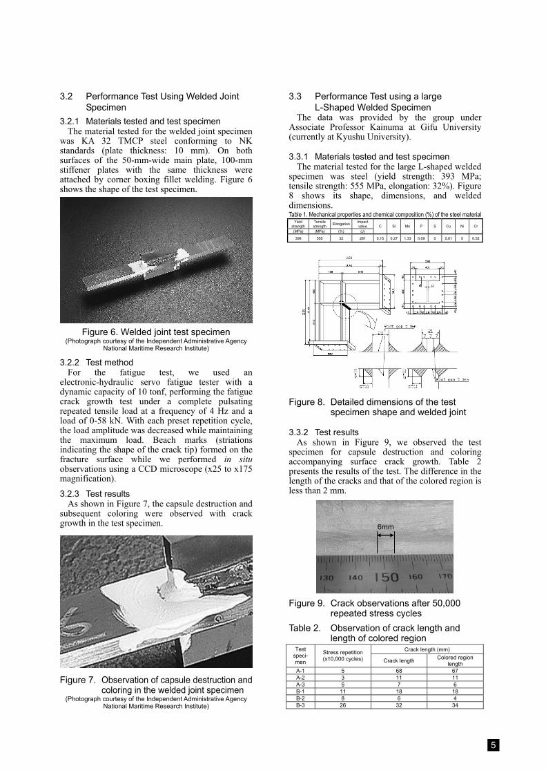
3.1.1 Materials tested and test specimen The materials tested for the flat-plate specimen
are a high-tensile steel SM490A (yield strength: 393 MPa; tensile strength 543 MPa) specimen and an aluminum alloy A5083P-O. Figure 4 shows their shapes and dimensions. A 10-mm long notch was created at the center of the specimen by electrical discharge machining.
Figure 4. Flat-plate test specimen with notch (Photograph courtesy of the Independent Administrative Agency
National Maritime Research Institute)
3.1.2 Test method An electronic-hydraulic servo fatigue tester with a
dynamic capacity of 10 tonf was used in the fatigue test, and the fatigue crack growth test was performed under a complete pulsating repeated tensile load at a frequency of 4 Hz and zero load ratio. With each preset repetition cycle, the load amplitude was reduced while maintaining the maximum load, and beach marks (striations indicating the shape of the crack tip) were formed on the fracture surface while we performed in situ
observations using a CCD microscope (x25 to x175 magnification).
3.1.3 Test results As shown in Figure 5, destruction of the capsule
and subsequent coloring were observed with crack growth in the test specimen (high-tensile steel SM490A).
Clear coloring was observed with the crack growth, and we confirmed the absence of problems with the crack detection mechanism. Average coating thickness was approximately 200 μm, accounted for by a 100-μm capsule-mixed coating layer and a 100-μm top coat layer.
The tests for the aluminum alloy (A5083P-O) specimen produced similarly excellent results.
After drying of top coat
N = 480,000
N = 600,000
Figure 5. Observation of capsule destruction and coloring accompanying crack growth
(Photograph courtesy of the Independent Administrative Agency National Maritime Research Institute)
5
3.2 Performance Test Using Welded Joint Specimen
3.2.1 Materials tested and test specimen The material tested for the welded joint specimen
was KA 32 TMCP steel conforming to NK standards (plate thickness: 10 mm). On both surfaces of the 50-mm-wide main plate, 100-mm stiffener plates with the same thickness were attached by corner boxing fillet welding. Figure 6 shows the shape of the test specimen.
Figure 6. Welded joint test specimen
(Photograph courtesy of the Independent Administrative Agency National Maritime Research Institute)
3.2.2 Test method For the fatigue test, we used an
electronic-hydraulic servo fatigue tester with a dynamic capacity of 10 tonf, performing the fatigue crack growth test under a complete pulsating repeated tensile load at a frequency of 4 Hz and a load of 0-58 kN. With each preset repetition cycle, the load amplitude was decreased while maintaining the maximum load. Beach marks (striations indicating the shape of the crack tip) formed on the fracture surface while we performed in situ observations using a CCD microscope (x25 to x175 magnification).
3.2.3 Test results As shown in Figure 7, the capsule destruction and
subsequent coloring were observed with crack growth in the test specimen.
Figure 7. Observation of capsule destruction and
coloring in the welded joint specimen (Photograph courtesy of the Independent Administrative Agency
National Maritime Research Institute)
3.3 Performance Test using a large L-Shaped Welded Specimen
The data was provided by the group under Associate Professor Kainuma at Gifu University (currently at Kyushu University).
3.3.1 Materials tested and test specimen The material tested for the large L-shaped welded
specimen was steel (yield strength: 393 MPa; tensile strength: 555 MPa, elongation: 32%). Figure 8 shows its shape, dimensions, and welded dimensions. Table 1. Mechanical properties and chemical composition (%) of the steel material
Yield strength
Tensile strength Elongation Impact
value (MPa) (MPa) (%) (J)
C Si Mn P S Cu Ni Cr
398 555 32 281 0.15 0.27 1.33 0.09 0 0.01 0 0.02
Figure 8. Detailed dimensions of the test
specimen shape and welded joint
3.3.2 Test results As shown in Figure 9, we observed the test
specimen for capsule destruction and coloring accompanying surface crack growth. Table 2 presents the results of the test. The difference in the length of the cracks and that of the colored region is less than 2 mm.
6mm
Figure 9. Crack observations after 50,000
repeated stress cycles Table 2. Observation of crack length and
length of colored region Crack length (mm) Test
speci- men
Stress repetition (x10,000 cycles) Crack length Colored region
length A-1 5 68 67 A-2 3 11 11 A-3 5 7 6 B-1 11 18 18 B-2 8 6 4 B-3 26 32 34
6
3.4 Weathering Test
3.4.1 Materials tested and test specimen The material tested was an aluminum plate
(A1050P) with dimensions of 1x60x100 mm (Figure 10). Both surface crack detection coatings, ThreeBond 2050 and ThreeBond 2050B, were used in the test.
Cut made by a small blade
Cut made by the back of a small blade (approx. 0.5 mm in width) Figure 10. Shape and dimension of the test
specimen for the weathering test
3.4.2 Test method The test specimen was exposed to an outdoor
environment for the time specified by JIS K-5600-7-6 or placed in a weather meter for a preset duration. The surface was then cut with a small blade for visual confirmation of coloring.
Exposure test condition: facing south at a 45° angle
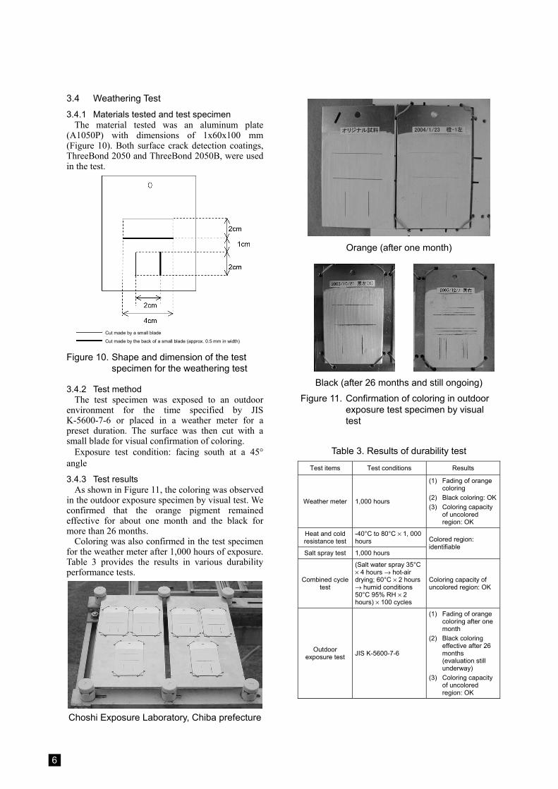
3.4.3 Test results As shown in Figure 11, the coloring was observed
in the outdoor exposure specimen by visual test. We confirmed that the orange pigment remained effective for about one month and the black for more than 26 months.
Coloring was also confirmed in the test specimen for the weather meter after 1,000 hours of exposure. Table 3 provides the results in various durability performance tests.
Choshi Exposure Laboratory, Chiba prefecture
Orange (after one month)
Black (after 26 months and still ongoing)
Figure 11. Confirmation of coloring in outdoor exposure test specimen by visual test
Table 3. Results of durability test
Test items Test conditions Results
Weather meter 1,000 hours
(1) Fading of orange coloring
(2) Black coloring: OK(3) Coloring capacity
of uncolored region: OK
Heat and cold resistance test
-40°C to 80°C × 1, 000 hours
Salt spray test 1,000 hours
Colored region: identifiable
Combined cycle test
(Salt water spray 35°C × 4 hours → hot-air drying; 60°C × 2 hours → humid conditions 50°C 95% RH × 2 hours) × 100 cycles
Coloring capacity of uncolored region: OK
Outdoor exposure test JIS K-5600-7-6
(1) Fading of orange coloring after one month
(2) Black coloring effective after 26 months (evaluation still underway)
(3) Coloring capacity of uncolored region: OK
7
4 Research Themes and Future Prospects
Our study confirmed that the two types of coatings used in this study, ThreeBond 2050 and ThreeBond 2050B, offer the basic performance required for a surface fatigue detection coating capable of assisting in visual tests by facilitating crack detection and potentially improving detection rates significantly. In future studies, we plan to challenge the following themes:
(1) Pigment weather resistance (2) Application to non-metal systems (3) Detection of micro surface fatigue cracks (4) Detection of stress distribution
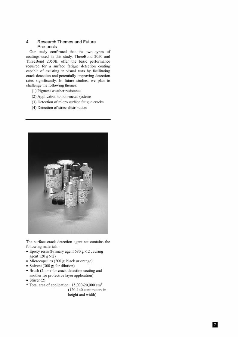
The surface crack detection agent set contains the following materials: • Epoxy resin (Primary agent 680 g × 2 , curing
agent 120 g × 2) • Microcapsules (200 g; black or orange) • Solvent (300 g; for dilution) • Brush (2; one for crack detection coating and
another for protective layer application) • Stirrer (2) * Total area of application: 15,000-20,000 cm2
(120-140 centimeters in height and width)
8
1456 Hazama-cho, Hachioji-shi, Tokyo 193-8533, JapanTel: 81-426-61-1333
Conclusion
Acknowledgements The research described here was undertaken as a joint development project with the Independent Administrative
Agency National Maritime Research Institute. We gratefully acknowledge the institute staff members as well as everyone who participated in the study.
In particular, we wish to thank Dr. Ichihiko Takahashi for his guidance and cooperation. We also wish to express our gratitude to Associate Professor Shigenobu Kainuma at Kyushu University for his
invaluable support and assistance as we performed our evaluations of surface crack detection coatings.
Hideki Takahashi Industrial Materials Development Division Development Department
Tomio Onoguchi Research Planning Division Research Department Research Center ThreeBond Co., Ltd.
Mitsuhiko Uchida R&D ThreeBond International, Inc. (Cincinnati)
References 1) The 226th meeting of the Shipbuilding, Research Association of Japan: Investigation of Rational Hull
Structure Design for Bulk Carriers-Final Report (in Japanese) (1996) 2) Roy R. Miron, Wayne Bilder and William Lademan, SmartPaint: A Structural Crack Monitoring Method,
NACE (National Association of Corrosion Engineers), Northern Area Eastern Conference, Ottawa (1999) 3) Ichihiko Takahashi, Michio Ushijima, Shigeru Akiyama, Atsushi Takada, and Noriyuki Kotani: Detection of
Fatigue Cracks with a Paint System for Inspections (in Japanese), Proceedings of the FY 2002 (2nd) Research Presentation Meeting of the Independent Administrative Agency National Maritime Research Institute, pp. 137-140 (2002)
4) Ichihiko Takahashi, Michio Ushijima, Shigeru Akiyama, Atsushi Takada, Tomio Onoguchi, and Mitsuhiko Uchida: Prototype and performance evaluations of a paint system for fatigue crack detection (in Japanese), Techno Marine – Journal of the Society of Naval Architects of Japan, vol. 871, pp. 70-73 (2003)
5) Tamotsu Kondo: Microcapsules (in Japanese) (Kyoritsu Shuppan Co., Ltd., Chemical One Point 13)


![A Soft Computing Approach to Crack Detection and Impact … · 2014. 4. 22. · the crack detection [1, 2]. The crack detection is done by measuring lamb wave signals using the dual](https://img.pdfslide.us/doc/110x75/60ec9be3b41124749d1a1a68/a-soft-computing-approach-to-crack-detection-and-impact-2014-4-22-the-crack.jpg)