Embed Size (px)
Citation preview


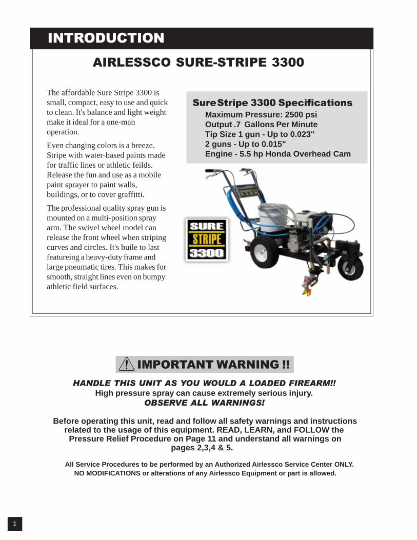


1. New Sprayer
Your Airlessco unit was factory tested in an antifreeze solution which was left in the pump. Beforeusing oil-base paint, flush with mineral spirits only. Before using water-base paint flush with soapywater, then do a clean water flush.
2. Changing Colors
Flush with a compatible solvent such as mineral spirits or water .
3. Changing from water-base to oil-base paint.Flush with soapy water, then mineral spirits.
4. Changing from oil-base to water-base paint.
Flush with mineral spirits, followed by soapy water, then do a clean water flush.
5. Storage
Oil-base paint: Flush with mineral spirits.
Water-base paint: Flush with water, then mineral spirits and leave the pump, hose and gun filled with mineral spirits. For longer storage, use mixture of mineral spirits and motor oil (half & half). Shut off the sprayer, follow Pressure Relief Procedure on page 11 to relieve pressure and make sure prime valve is left OPEN.
6. Start up after storage
Before using water-base paint, flush with soapy water and then do a clean water flush. When usingoil-base paint, flush out the mineral spirits with the material to be sprayed.
FLUSHINGRead prior to using your sprayer
6
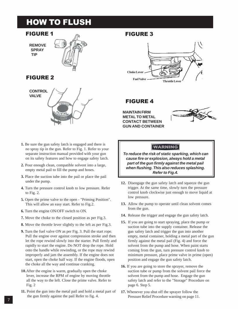
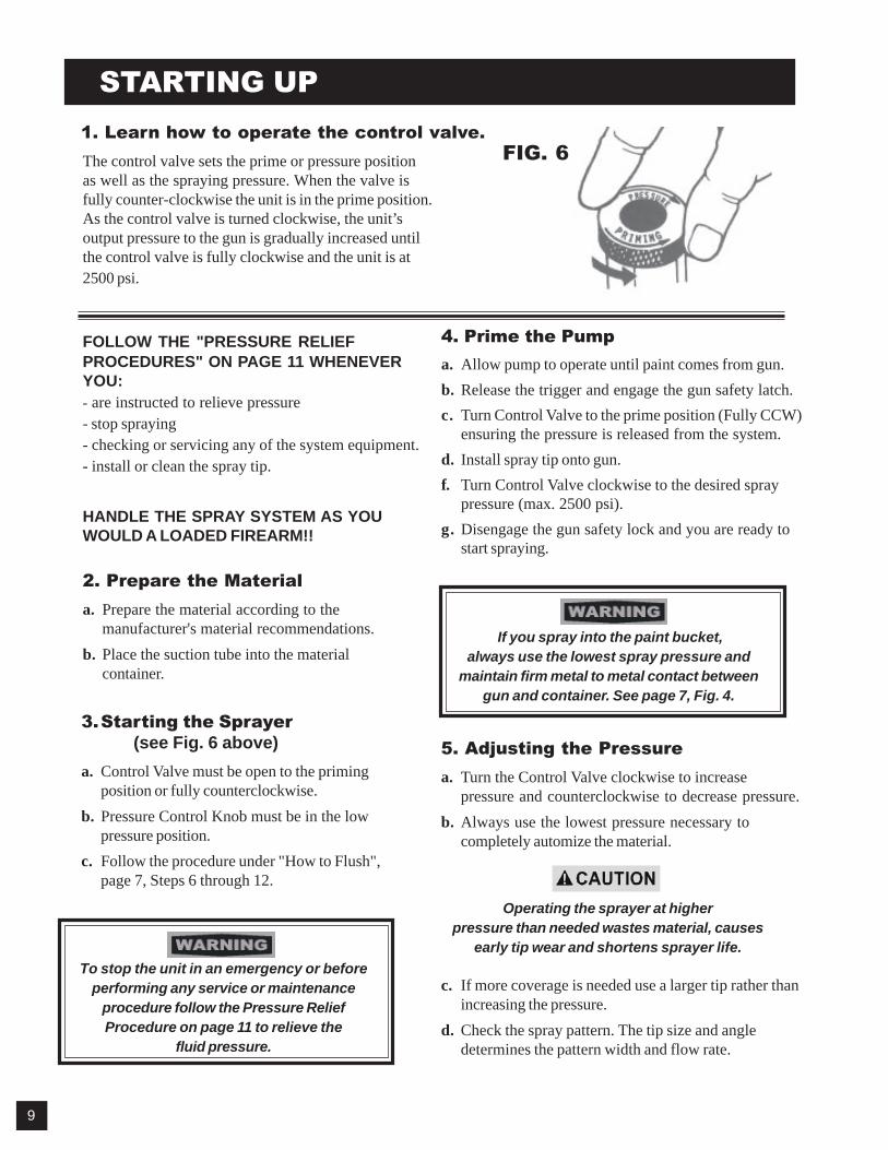
FIGURE 2
FIGURE 1
REMOVE SPRAY TIP
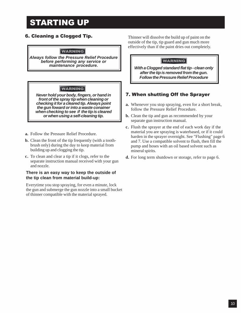
FIGURE 3
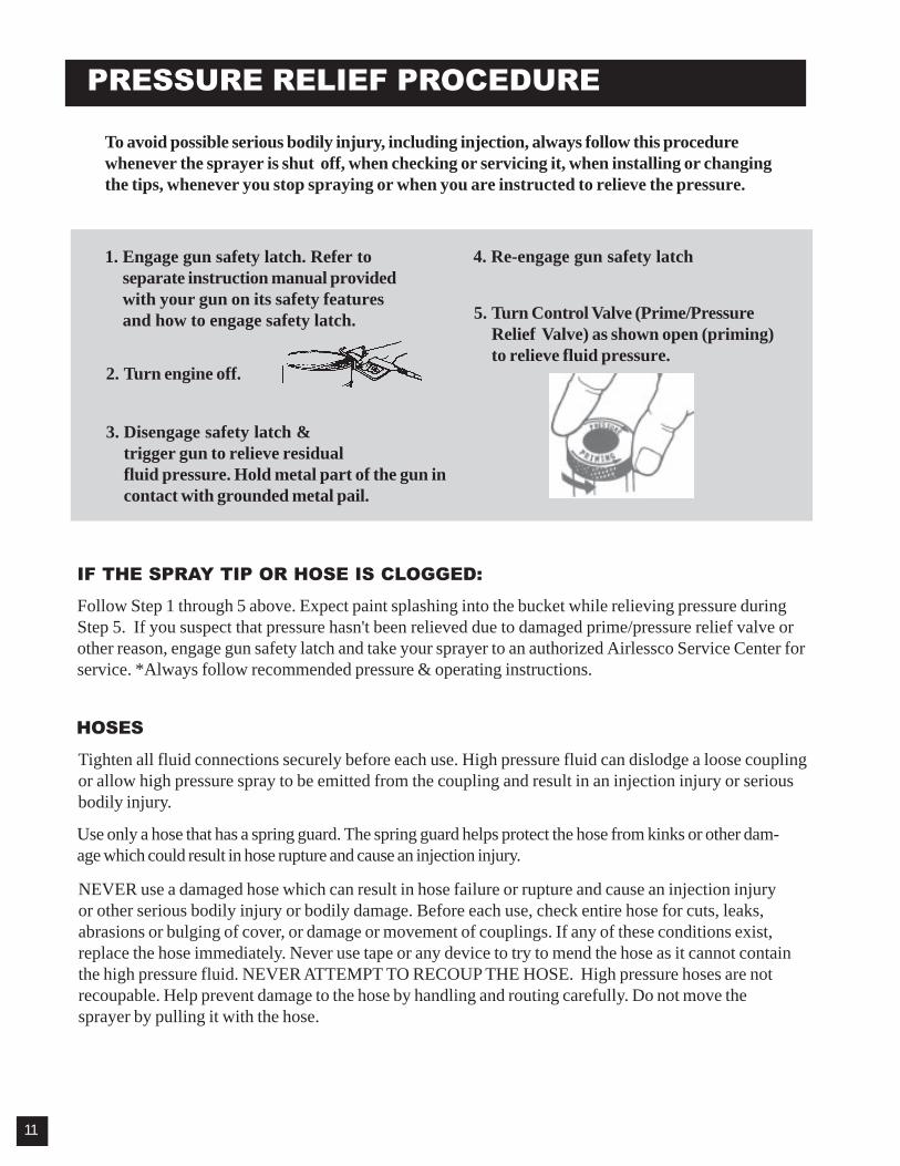
FIGURE 4
MAINTAIN FIRMMETAL TO METALCONTACT BETWEENGUN AND CONTAINER
1. Be sure the gun safety latch is engaged and there isno spray tip in the gun. Refer to Fig. 1. Refer to yourseparate instruction manual provided with your gunon its safety features and how to engage safety latch.
2. Pour enough clean, compatible solvent into a large,empty metal pail to fill the pump and hoses.
3. Place the suction tube into the pail or place the pailunder the pump.
4. Turn the pressure control knob to low pressure. Referto Fig. 2.
5. Open the prime valve to the open - "Priming Position".This will allow an easy start. Refer to Fig.2.
6. Turn the engine ON/OFF switch to ON.
7. Move the choke to the closed position as per Fig.3.
8. Move the throttle lever slightly to the left as per Fig.3.
9. Turn the fuel valve ON as per Fig. 3. Pull the start rope.Pull the engine over against compression stroke and thenlet the rope rewind slowly into the starter . Pull firmly andrapidly to start the engine. Do NOT drop the rope. Holdonto the handle while rewinding, or the rope may rewindimproperly and jam the assembly. If the engine does notstart, open the choke half way. If the engine floods, openthe choke all the way and continue cranking.
10.After the engine is warm, gradually open the chokelever, increase the RPM of engine by moving throttleall the way to the left. Close the prime valve. Refer toFig. 2
11. Point the gun into the metal pail and hold a metal part ofthe gun firmly against the pail Refer to fig. 4 .
12. Disengage the gun safety latch and squeeze the guntrigger. At the same time, slowly turn the pressurecontrol knob clockwise just enough to move liquid atlow pressure.
13. Allow the pump to operate until clean solvent comesfrom the gun.
14. Release the trigger and engage the gun safety latch.
15. If you are going to start spraying, place the pump orsuction tube into the supply container . Release thegun safety latch and trigger the gun into anotherempty, metal container, holding a metal part of the gunfirmly against the metal pail (Fig. 4) and force thesolvent from the pump and hose. When paint startscoming from the gun, turn pressure control knob tominimum pressure, place prime valve in prime (open)position and engage the gun safety latch.
16. If you are going to store the sprayer , remove thesuction tube or pump from the solvent pail force thesolvent from the pump and hose. Engage the gunsafety latch and refer to the "Storage" Procedure onpage 6. Step 5.
17. Whenever you shut off the sprayer follow thePressure Relief Procedure warning on page 11.
HOW TO FLUSH
To reduce the risk of static sparking, which cancause fire or explosion, always hold a metalpart of the gun firmly against the metal pail
when flushing. This also reduces splashing.Refer to Fig.4.
Choke Lever
Fuel ValveThrottle Lever
7
CONTROLVALVE

SETTING UP
3. Check the Engine Oil Level.a. Unscrew the oil fill plug. The dipstick is attached to
the plug.b. Without threading the plug into place, check to be
sure the oil is up to the top mark on the dipstick.c. If oil is needed, refer to
engine manual.
NOTE: Unit is shipped WITH OIL in engine and clutch.
5. Fill the Fuel Tank.
Fuel spilled on a hot surface can cause a fire or explosion and causeserious bodily injury and property damage. Always shut off the engine
and let it cool before filling the tank, and carefully follow Steps a-c below,being sure not to spill any fuel.
a. Close the fuel shutoff valve.b. Use only clean, fresh, well-known brands of
unleaded regular grade gasoline.c. Remove the fuel cap and fill tank, Be sure the air
vent in the fill cap is not plugged so fuel can flow tothe carburetor, then replace the cap.
6. Flush the sprayer.See "Flushing". Your new pump was factorytested in an ant-freeze solution and it must be flushedbefore using.
NOTE: Prior to striping, see LinestripingOperations (page 4) for correct gun arm set up, to get proper sized lines.
1. Attach handle assembly.Refer to Figure 5. Complete steps a - d for bothsides of the handle.
a. Slide plate (Item 1) over clamp (Item 2).b. Place clamp with plate attached over frame
(Item 4), so that the holes in the clamp are inalignment with the holes in the frame.
c. Put the handle (Item 5) down through theholes in the clamp and frame.
d. Set handle to desired height and tighten thescrew (Item 3) so that the plate is snugagainst the frame.
2. Install the gun arm assembly.Refer to Figure 6.
a. Choose which side of the frame to mount thegun arm.
b. Complete Steps a - c from attaching the handleassembly (above), except mounting the gunarm instead of the handle.
c. Set gun arm to desired height and tighten theadjustable handle (Item 3) until the plate issnug against the frame. Note: The adjustablehandle can be ratchet by lifting up on thehandle.
PlateClamp
Adjustable Handle
Frame
Gun Arm
Upper Limit
Lower Limit
FIGURE 5 FIGURE 6
FIGURE 7
FIGURE 8
PlateClamp
Screw
Frame
Handle
4. Check Clutch Oil Level.a. Complete steps a-c of Check the Engine Oil Level, except using the clutch dipstick.
8
STARTING UP
The control valve sets the prime or pressure positionas well as the spraying pressure. When the valve isfully counter-clockwise the unit is in the prime position.As the control valve is turned clockwise, the unit’soutput pressure to the gun is gradually increased untilthe control valve is fully clockwise and the unit is at2500 psi.
FOLLOW THE "PRESSURE RELIEFPROCEDURES" ON PAGE 11 WHENEVERYOU:- are instructed to relieve pressure- stop spraying- checking or servicing any of the system equipment.- install or clean the spray tip.
HANDLE THE SPRAY SYSTEM AS YOUWOULD A LOADED FIREARM!!
2. Prepare the Materiala. Prepare the material according to the
manufacturer's material recommendations.b. Place the suction tube into the material
container.
4. Prime the Pumpa. Allow pump to operate until paint comes from gun.b. Release the trigger and engage the gun safety latch.c. Turn Control Valve to the prime position (Fully CCW)
ensuring the pressure is released from the system.d. Install spray tip onto gun.f. Turn Control Valve clockwise to the desired spray
pressure (max. 2500 psi).g. Disengage the gun safety lock and you are ready to
start spraying.
To stop the unit in an emergency or beforeperforming any service or maintenance
procedure follow the Pressure ReliefProcedure on page 11 to relieve the
fluid pressure.
3.Starting the Sprayer(see Fig. 6 above)
a. Control Valve must be open to the primingposition or fully counterclockwise.
b. Pressure Control Knob must be in the lowpressure position.
c. Follow the procedure under "How to Flush",page 7, Steps 6 through 12.
5. Adjusting the Pressurea. Turn the Control Valve clockwise to increase
pressure and counterclockwise to decrease pressure.b. Always use the lowest pressure necessary to
completely automize the material.
c. If more coverage is needed use a larger tip rather thanincreasing the pressure.
d. Check the spray pattern. The tip size and angledetermines the pattern width and flow rate.
If you spray into the paint bucket,always use the lowest spray pressure and
maintain firm metal to metal contact betweengun and container. See page 7, Fig. 4.
Operating the sprayer at higherpressure than needed wastes material, causes
early tip wear and shortens sprayer life.
9
1. Learn how to operate the control valve.FIG. 6
6. Cleaning a Clogged Tip.
Always follow the Pressure Relief Procedurebefore performing any service or
maintenance procedure.
Never hold your body, fingers, or hand infront of the spray tip when cleaning or
checking it for a cleared tip. Always pointthe gun foward or into a waste conainer
when checking to see if the tip is clearedor when using a self-cleaning tip.
a. Follow the Pressure Relief Procedure.b. Clean the front of the tip frequently (with a tooth-
brush only) during the day to keep material frombuilding up and clogging the tip.
c. To clean and clear a tip if it clogs, refer to theseparate instruction manual received with your gunand nozzle.
There is an easy way to keep the outside ofthe tip clean from material build-up:
Everytime you stop spraying, for even a minute, lockthe gun and submerge the gun nozzle into a small bucketof thinner compatible with the material sprayed.
Thinner will dissolve the build up of paint on theoutside of the tip, tip guard and gun much moreeffectively than if the paint dries out completely.
With a Clogged standard flat tip - clean onlyafter the tip is removed from the gun.Follow the Pressure Relief Procedure
7. When shutting Off the Sprayer
a. Whenever you stop spraying, even for a short break,follow the Pressure Relief Procedure.
b. Clean the tip and gun as recommended by yourseparate gun instruction manual.
c. Flush the sprayer at the end of each work day if thematerial you are spraying is waterbased, or if it couldharden in the sprayer overnight. See "Flushing" page 6and 7. Use a compatible solvent to flush, then fill thepump and hoses with an oil based solvent such asmineral spirits.
d. For long term shutdown or storage, refer to page 6.
STARTING UP
10
PRESSURE RELIEF PROCEDURE
Tighten all fluid connections securely before each use. High pressure fluid can dislodge a loose couplingor allow high pressure spray to be emitted from the coupling and result in an injection injury or seriousbodily injury.
HOSES
2. Turn engine off.
3. Disengage safety latch &trigger gun to relieve residualfluid pressure. Hold metal part of the gun incontact with grounded metal pail.
4. Re-engage gun safety latch1. Engage gun safety latch. Refer toseparate instruction manual providedwith your gun on its safety featuresand how to engage safety latch. 5. Turn Control Valve (Prime/Pressure
Relief Valve) as shown open (priming)to relieve fluid pressure.
To avoid possible serious bodily injury, including injection, always follow this procedurewhenever the sprayer is shut off, when checking or servicing it, when installing or changingthe tips, whenever you stop spraying or when you are instructed to relieve the pressure.
IF THE SPRAY TIP OR HOSE IS CLOGGED:
Follow Step 1 through 5 above. Expect paint splashing into the bucket while relieving pressure duringStep 5. If you suspect that pressure hasn't been relieved due to damaged prime/pressure relief valve orother reason, engage gun safety latch and take your sprayer to an authorized Airlessco Service Center forservice. *Always follow recommended pressure & operating instructions.
NEVER use a damaged hose which can result in hose failure or rupture and cause an injection injuryor other serious bodily injury or bodily damage. Before each use, check entire hose for cuts, leaks,abrasions or bulging of cover, or damage or movement of couplings. If any of these conditions exist,replace the hose immediately. Never use tape or any device to try to mend the hose as it cannot containthe high pressure fluid. NEVER ATTEMPT TO RECOUP THE HOSE. High pressure hoses are notrecoupable. Help prevent damage to the hose by handling and routing carefully. Do not move thesprayer by pulling it with the hose.
Use only a hose that has a spring guard. The spring guard helps protect the hose from kinks or other dam-age which could result in hose rupture and cause an injection injury.
11
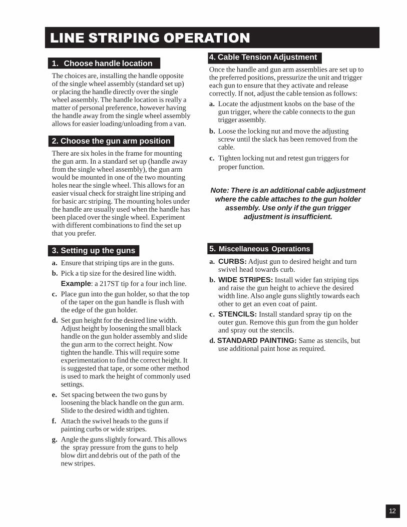
c. Tighten locking nut and retest gun triggers forproper function.
Note: There is an additional cable adjustmentwhere the cable attaches to the gun holder
assembly. Use only if the gun triggeradjustment is insufficient.
5. Miscellaneous Operations
a. CURBS: Adjust gun to desired height and turnswivel head towards curb.
b. WIDE STRIPES: Install wider fan striping tipsand raise the gun height to achieve the desiredwidth line. Also angle guns slightly towards eachother to get an even coat of paint.
c. STENCILS: Install standard spray tip on theouter gun. Remove this gun from the gun holderand spray out the stencils.
d. STANDARD PAINTING: Same as stencils, butuse additional paint hose as required.
LINE STRIPING OPERATION
1. Choose handle location
The choices are, installing the handle oppositeof the single wheel assembly (standard set up)or placing the handle directly over the singlewheel assembly. The handle location is really amatter of personal preference, however havingthe handle away from the single wheel assemblyallows for easier loading/unloading from a van.
2. Choose the gun arm position
There are six holes in the frame for mountingthe gun arm. In a standard set up (handle awayfrom the single wheel assembly), the gun armwould be mounted in one of the two mountingholes near the single wheel. This allows for aneasier visual check for straight line striping andfor basic arc striping. The mounting holes underthe handle are usually used when the handle hasbeen placed over the single wheel. Experimentwith different combinations to find the set upthat you prefer.
3. Setting up the guns
a. Ensure that striping tips are in the guns.b. Pick a tip size for the desired line width.
Example: a 217ST tip for a four inch line.c. Place gun into the gun holder, so that the top
of the taper on the gun handle is flush withthe edge of the gun holder.
d. Set gun height for the desired line width.Adjust height by loosening the small blackhandle on the gun holder assembly and slidethe gun arm to the correct height. Nowtighten the handle. This will require someexperimentation to find the correct height. Itis suggested that tape, or some other methodis used to mark the height of commonly usedsettings.
e. Set spacing between the two guns byloosening the black handle on the gun arm.Slide to the desired width and tighten.
f. Attach the swivel heads to the guns ifpainting curbs or wide stripes.
g. Angle the guns slightly forward. This allowsthe spray pressure from the guns to helpblow dirt and debris out of the path of thenew stripes.
4. Cable Tension Adjustment
Once the handle and gun arm assemblies are set up tothe preferred positions, pressurize the unit and triggereach gun to ensure that they activate and releasecorrectly. If not, adjust the cable tension as follows:a. Locate the adjustment knobs on the base of the
gun trigger, where the cable connects to the guntrigger assembly.
b. Loose the locking nut and move the adjustingscrew until the slack has been removed from thecable.
12
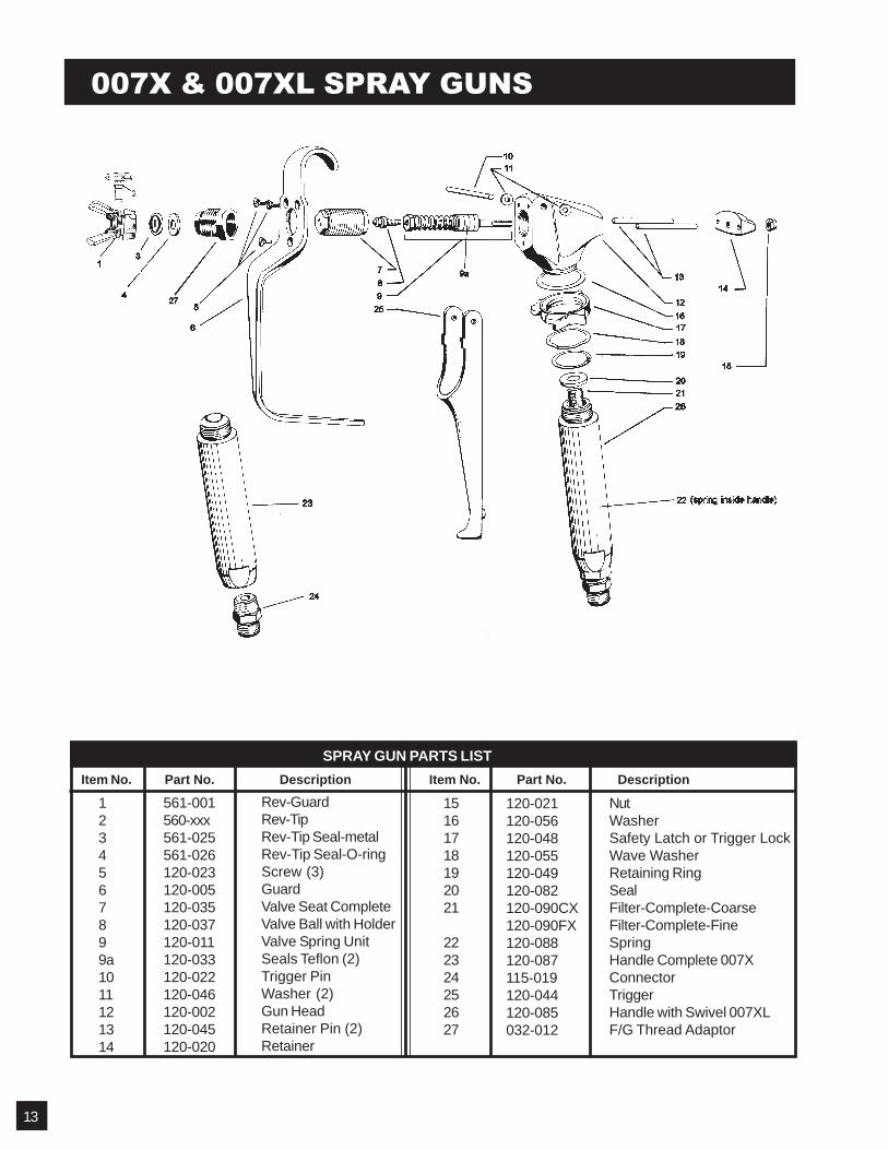
SPRAY GUN PARTS LIST
007X & 007XL SPRAY GUNS
Item No. Part No. Description Item No. Part No. Description
1234567899a1011121314
561-001560-xxx561-025561-026120-023120-005120-035120-037120-011120-033120-022120-046120-002120-045120-020
Rev-GuardRev-TipRev-Tip Seal-metalRev-Tip Seal-O-ringScrew (3)GuardValve Seat CompleteValve Ball with HolderValve Spring UnitSeals PTFE (2)Trigger PinWasher (2)Gun HeadRetainer Pin (2)Retainer
15161718192021
222324252627
120-021120-056120-048120-055120-049120-082120-090CX120-090FX120-088120-087115-019120-044120-085032-012
NutWasherSafety Latch or Trigger LockWave WasherRetaining RingSealFilter-Complete-CoarseFilter-Complete-FineSpringHandle Complete 007XConnectorTriggerHandle with Swivel 007XLF/G Thread Adaptor
13
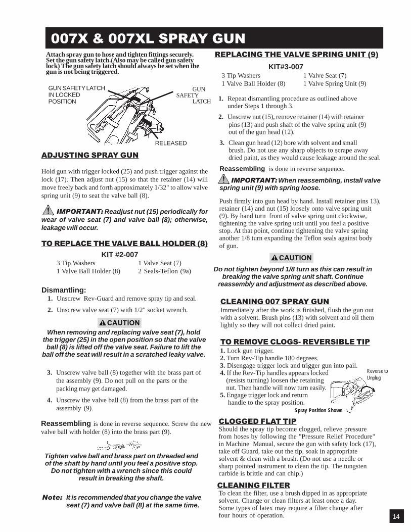
1. Lock gun trigger.2. Turn Rev-Tip handle 180 degrees.3. Disengage trigger lock and trigger gun into pail.4. If the Rev-Tip handles appears locked
(resists turning) loosen the retainingnut. Then handle will now turn easily.
5. Engage trigger lock and return handle to the spray position.
ADJUSTING SPRAY GUN
Hold gun with trigger locked (25) and push trigger against thelock (17). Then adjust nut (15) so that the retainer (14) willmove freely back and forth approximately 1/32" to allow valvespring unit (9) to seat the valve ball (8).
IMPORTANT: Readjust nut (15) periodically forwear of valve seat (7) and valve ball (8); otherwise,leakage will occur.
TO REPLACE THE VALVE BALL HOLDER (8) KIT #2-007
3 Tip Washers 1 Valve Seat (7)1 Valve Ball Holder (8) 2 Seals-PTFE (9a)
REPLACING THE VALVE SPRING UNIT (9) KIT#3-007
3 Tip Washers 1 Valve Seat (7)1 Valve Ball Holder (8) 1 Valve Spring Unit (9)
When removing and replacing valve seat (7), hold the trigger (25) in the open position so that the valve
ball (8) is lifted off the valve seat. Failure to lift theball off the seat will result in a scratched leaky valve.
3. Unscrew valve ball (8) together with the brass part ofthe assembly (9). Do not pull on the parts or thepacking may get damaged.
4. Unscrew the valve ball (8) from the brass part of theassembly (9).
Reassembling is done in reverse sequence. Screw the newvalve ball with holder (8) into the brass part (9).
Tighten valve ball and brass part on threaded endof the shaft by hand until you feel a positive stop.
Do not tighten with a wrench since this couldresult in breaking the shaft.
Note: It is recommended that you change the valveseat (7) and valve ball (8) at the same time.
1. Repeat dismantling procedure as outlined aboveunder Steps 1 through 3.
2. Unscrew nut (15), remove retainer (14) with retainerpins (13) and push shaft of the valve spring unit (9)out of the gun head (12).
3. Clean gun head (12) bore with solvent and smallbrush. Do not use any sharp objects to scrape awaydried paint, as they would cause leakage around the seal.
Reassembling is done in reverse sequence.
IMPORTANT: When reassembling, install valvespring unit (9) with spring loose.
CLEANING 007 SPRAY GUNImmediately after the work is finished, flush the gun outwith a solvent. Brush pins (13) with solvent and oil themlightly so they will not collect dried paint.
TO REMOVE CLOGS- REVERSIBLE TIP
Push firmly into gun head by hand. Install retainer pins 13),retainer (14) and nut (15) loosely onto valve spring unit(9). By hand turn front of valve spring unit clockwise,tightening the valve spring unit until you feel a positivestop. At that point, continue tightening the valve springanother 1/8 turn expanding the PTFE seals against bodyof gun.
CLEANING FILTERTo clean the filter, use a brush dipped in as appropriatesolvent. Change or clean filters at least once a day .Some types of latex may require a filter change afterfour hours of operation.
007X & 007XL SPRAY GUN
GUN SAFETY LATCHIN LOCKEDPOSITION
GUNSAFETY
LATCH
RELEASED
Attach spray gun to hose and tighten fittings securely.Set the gun safety latch.(Also may be called gun safetylock) The gun safety latch should always be set when thegun is not being triggered.
CLOGGED FLAT TIPShould the spray tip become clogged, relieve pressurefrom hoses by following the "Pressure Relief Procedure"in Machine Manual, secure the gun with safety lock (17),take off Guard, take out the tip, soak in appropriatesolvent & clean with a brush. (Do not use a needle orsharp pointed instrument to clean the tip. The tungstencarbide is brittle and can chip.)
Reverse toUnplug
Spray Position Shown
Do not tighten beyond 1/8 turn as this can result inbreaking the valve spring unit shaft. Continue
reassembly and adjustment as described above.Dismantling:
1. Unscrew Rev-Guard and remove spray tip and seal.
2. Unscrew valve seat (7) with 1/2" socket wrench.
14
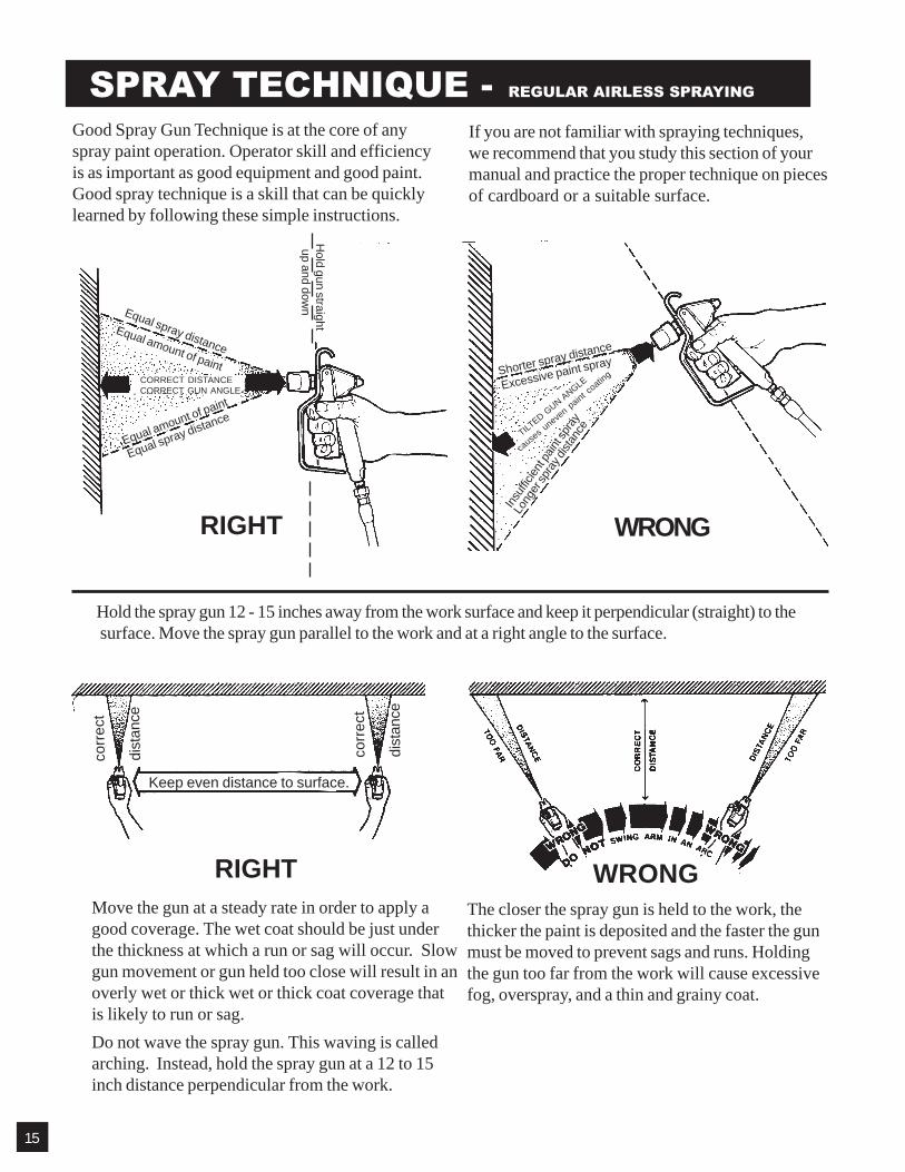
SPRAY TECHNIQUE - REGULAR AIRLESS SPRAYING
The closer the spray gun is held to the work, thethicker the paint is deposited and the faster the gunmust be moved to prevent sags and runs. Holdingthe gun too far from the work will cause excessivefog, overspray, and a thin and grainy coat.
Good Spray Gun Technique is at the core of anyspray paint operation. Operator skill and efficiencyis as important as good equipment and good paint.Good spray technique is a skill that can be quicklylearned by following these simple instructions.
If you are not familiar with spraying techniques,we recommend that you study this section of yourmanual and practice the proper technique on piecesof cardboard or a suitable surface.
RIGHT WRONG
Equal spray distanceEqual amount of paint
Equal amount of paint
Equal spray distance
Hold gun straight
up and down
TILTED G
UN ANGLE
cause
s uneve
n paint coatin
gShorter spray distance
Excessive paint spray
Insuff
icien
t pain
t spr
ay
Long
er sp
ray d
istan
ce
CORRECT DISTANCECORRECT GUN ANGLE
Hold the spray gun 12 - 15 inches away from the work surface and keep it perpendicular (straight) to the surface. Move the spray gun parallel to the work and at a right angle to the surface.
WRONGMove the gun at a steady rate in order to apply agood coverage. The wet coat should be just underthe thickness at which a run or sag will occur. Slowgun movement or gun held too close will result in anoverly wet or thick wet or thick coat coverage thatis likely to run or sag.Do not wave the spray gun. This waving is calledarching. Instead, hold the spray gun at a 12 to 15inch distance perpendicular from the work.
RIGHT
corr
ect
dist
ance
corr
ect
dist
ance
Keep even distance to surface.
15

SPRAY TECHNIQUE - REGULAR AIRLESS SPRAYING
"Inside" and "outside" corners can be sprayed.Aim the spray gun toward the center of the corner.The spray pattern is divided in half, and the edgesof the spray pattern on both walls are the same.
Always use the lowest pressure possible to obtaindesirable results.Test the spray pattern on a piece of cardboard orother surface.
It is important to "trigger" the gun after gun movement(arm movement) has started and release trigger (shutgun off) before gun movement ends. Gun movement isalways longer than actual paint (spray) stroke. In thatmanner, even blending and uniform paint coat thicknessis achieved over the entire surface. When the gun is inmotion as the trigger is pulled, it deposits an evenamount of paint.
Overlap the previous pass by half the width of thespray pattern. Aim at the bottom of the previous pass.
Spray with uniform strokes from left to right andfrom right to left, holding stroke speed, distance,lapping, and triggering as uniform as possible.
Adjust pressure control knob so that paint is com-pletely atomized from the spray gun. Insufficientpressure will result in "tailing".
Too much pressure will result in excess fog andoverspray, excessive tip wear, and increasedsprayer wear and tear.
16

AIRLESS SPRAY GUN OPERATIONDEFECTS CAUSE CORRECTION
Coarse spray Low pressure Increase the pressure.
Excessive fogging High pressure Reduce the pressure to satisfactory(overspray) pattern distribution.
Material too thin Use less thinner.
Pattern too wide Spray angle too large Use smaller spray angle tip.
Pattern too narrow Spray angle too small Use larger spray angle tip. (If coverage is OK, try tip in same nozzle group)
Too much material Nozzle too large Use next smaller nozzle.Material too thinPressure too high Reduce pressure.
Too little material Nozzle too small Use next larger nozzle.Material too thick
Thin distribution in Worn tip Change for new tip.center of pattern Wrong tip Use nozzle with a narrow spray angle."horns"
Thick skin on work Material too viscous Thin cautiously.Application too heavy Reduce pressure and/or use tip in next
smaller nozzle group.
Coating fails to Material too viscous Thin cautiously.close & smooth over
Spray pattern irreg- Orifice clogged Clean carefully.ular, deflected Tip damaged Replace with new tip.
Craters or pock Solvent balance Use 1 to 3% "short" solvents & themarks, bubbles remainder "longsolvents". (This is
most likely to happenwith material oflow viscosity, lacquers etc.)
Clogged screens Debris in paint Clean screenCoarse paint pigments Use coarse gun filter screen.Incompatible paint Use coarser screen for larger orifice tips.mixture & thinners. If thinner was added, test to see if a drop
on top of paint mixes or flattens out onthe surface. If not, try different thinner infresh batch of paint.
17
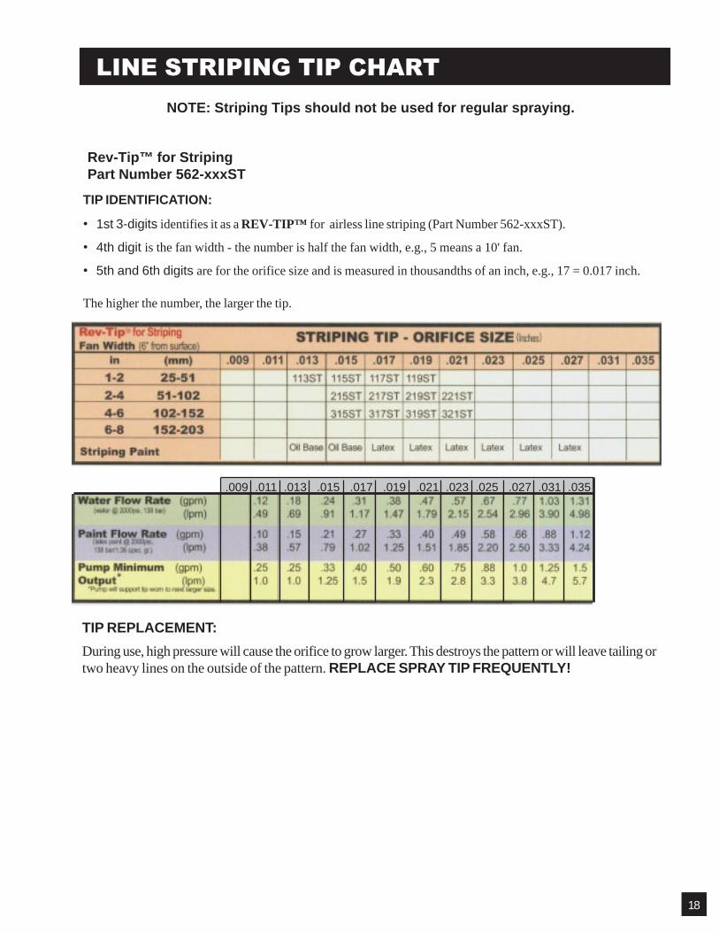
LINE STRIPING TIP CHARTNOTE: Striping Tips should not be used for regular spraying.
TIP REPLACEMENT:
During use, high pressure will cause the orifice to grow larger. This destroys the pattern or will leave tailing ortwo heavy lines on the outside of the pattern. REPLACE SPRAY TIP FREQUENTLY!
Rev-Tip™ for StripingPart Number 562-xxxST
TIP IDENTIFICATION:
• 1st 3-digits identifies it as a REV-TIP™ for airless line striping (Part Number 562-xxxST).
• 4th digit is the fan width - the number is half the fan width, e.g., 5 means a 10' fan.
• 5th and 6th digits are for the orifice size and is measured in thousandths of an inch, e.g., 17 = 0.017 inch.
The higher the number, the larger the tip.
.009 .011 .013 .015 .017 .019 .021 .023 .025 .027 .031 .035
18
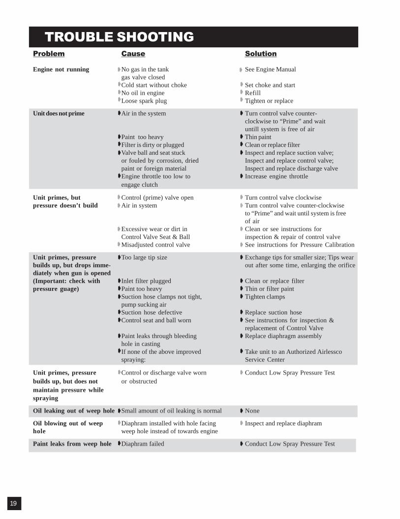
Problem Cause Solution
Engine not running No gas in the tank See Engine Manualgas valve closedCold start without choke Set choke and startNo oil in engine RefillLoose spark plug Tighten or replace
Unit does not prime Air in the system Turn control valve counter-clockwise to “Prime” and waituntill system is free of air
Paint too heavy Thin paintFilter is dirty or plugged Clean or replace filterValve ball and seat stuck Inspect and replace suction valve;or fouled by corrosion, dried Inspect and replace control valve;paint or foreign material Inspect and replace discharge valveEngine throttle too low to Increase engine throttleengage clutch
Unit primes, but Control (prime) valve open Turn control valve clockwisepressure doesn’t build Air in system Turn control valve counter -clockwise
to “Prime” and wait until system is freeof air
Excessive wear or dirt in Clean or see instructions forControl Valve Seat & Ball inspection & repair of control valveMisadjusted control valve See instructions for Pressure Calibration
Unit primes, pressure Too large tip size Exchange tips for smaller size; Tips wearbuilds up, but drops imme- out after some time, enlarging the orificediately when gun is opened(Important: check with Inlet filter plugged Clean or replace filterpressure guage) Paint too heavy Thin or filter paint
Suction hose clamps not tight, Tighten clampspump sucking airSuction hose defective Replace suction hoseControl seat and ball worn See instructions for inspection &
replacement of Control ValvePaint leaks through bleeding Replace diaphragm assemblyhole in castingIf none of the above improved Take unit to an Authorized Airlesscospraying: Service Center
Unit primes, pressure Control or discharge valve worn Conduct Low Spray Pressure Testbuilds up, but does not or obstructedmaintain pressure whilespraying
Oil leaking out of weep hole Small amount of oil leaking is normal None
Oil blowing out of weep Diaphram installed with hole facing Inspect and replace diaphramhole weep hole instead of towards engine
Paint leaks from weep hole Diaphram failed Conduct Low Spray Pressure Test
TROUBLE SHOOTING
19
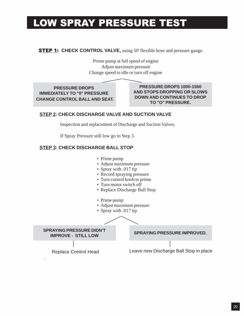
STEP 1: CHECK CONTROL VALVE, using 50' flexible hose and pressure gauge.
Prime pump at full speed of engineAdjust maximum pressure
Change speed to idle or turn off engine
PRESSURE DROPSIMMEDIATELY TO "0" PRESSURE
PRESSURE DROPS 1000-1500AND STOPS DROPPING OR SLOWSDOWN AND CONTINUES TO DROP
TO "O" PRESSURE.
STEP 2: CHECK DISCHARGE VALVE AND SUCTION VALVE
Inspection and replacement of Discharge and Suction Valves.
If Spray Pressure still low go to Step 3.
STEP 3: CHECK DISCHARGE BALL STOP
• Prime pump• Adjust maximum pressure• Spray with .017 tip• Record spraying pressure• Turn control knob to prime• Turn motor switch off• Replace Discharge Ball Stop
• Prime pump• Adjust maximum pressure• Spray with .017 tip
SPRAYING PRESSURE DIDN'TIMPROVE - STILL LOW
SPRAYING PRESSURE IMPROVED.
Replace Control Head .
Leave new Discharge Ball Stop in place
LOW SPRAY PRESSURE TEST
CHANGE CONTROL BALL AND SEAT.
20
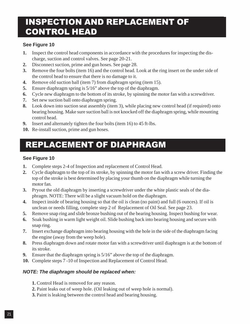
INSPECTION AND REPLACEMENT OFCONTROL HEAD
REPLACEMENT OF DIAPHRAGM
See Figure 10
1. Inspect the control head components in accordance with the procedures for inspecting the dis-charge, suction and control valves. See page 20-21.
2. Disconnect suction, prime and gun hoses. See page 28.3. Remove the four bolts (item 16) and the control head. Look at the ring insert on the under side of
the control head to ensure that there is no damage to it.4. Remove old suction ball (item 7) from diaphragm spring (item 15).5. Ensure diaphragm spring is 5/16” above the top of the diaphragm.6. Cycle new diaphragm to the bottom of its stroke, by spinning the motor fan with a screwdriver.7. Set new suction ball onto diaphragm spring.8. Look down into suction seat assembly (item 3), while placing new control head (if required) onto
bearing housing. Make sure suction ball is not knocked off the diaphragm spring, while mountingcontrol head.
9. Insert and alternately tighten the four bolts (item 16) to 45 ft-lbs.10. Re-install suction, prime and gun hoses.
See Figure 10
1. Complete steps 2-4 of Inspection and replacement of Control Head.2. Cycle diaphragm to the top of its stroke, by spinning the motor fan with a screw driver. Finding the
top of the stroke is best determined by placing your thumb on the diaphragm while turning themotor fan.
3. Pryout the old diaphragm by inserting a screwdriver under the white plastic seals of the dia-phragm. NOTE: There will be a slight vacuum hold on the diaphragm.
4. Inspect inside of bearing housing so that the oil is clean (no paint) and full (6 ounces). If oil isunclean or needs filling, complete step 2 of Replacement of Oil Seal. See page 23.
5. Remove snap ring and slide bronze bushing out of the bearing housing. Inspect bushing for wear.6. Soak bushing in warm light weight oil. Slide bushing back into bearing housing and secure with
snap ring.7. Insert exchange diaphragm into bearing housing with the hole in the side of the diaphragm facing
the engine (away from the weep hole).8. Press diaphragm down and rotate motor fan with a screwdriver until diaphragm is at the bottom of
its stroke.9. Ensure that the diaphragm spring is 5/16” above the top of the diaphragm.10. Complete steps 7 -10 of Inspection and Replacement of Control Head.
NOTE: The diaphragm should be replaced when:
1. Control Head is removed for any reason.2. Paint leaks out of weep hole. (Oil leaking out of weep hole is normal).3. Paint is leaking between the control head and bearing housing.
21

INSPECTION AND REPLACEMENT OFCONTROL VALVE, BALL AND SEAT
INSPECTION AND REPLACEMENT OFSUCTION VALVE
See Figure 10.
1. Use a wrench to unscrew the control valve (item 14) with ring seal (item 17).2. Make sure that the control valve knob turns freely and that its stem is not worn unevenly, mush-
roomed or otherwise damaged.3. Remove TC guide (item 18), verify that it is unbroken, clean and notch side is up.4. Remove control ball (item 12). Inspect for any cuts, scratches, chips, rust or other damage.5. Use a 7/16” allen wrench to unscrew the control seat (item 11) from the pump head (item 2).
Clean seat and inspect bevel edge for damage. Also ensure that the gasket on the underside ofthe seat is intact.
6. If no obvious damage to the control ball and seat, place ball into seat and fill with water. If waterleaks out between ball and seat, they must be replaced.
7. Replace control valve, ball, seat and/or TC guide as necessary.8. Clean and inspect pump head opening, where the control seat was installed.9. Grease pump head opening with multipurpose grease.10. Screw control seat into pump head and torque to 85 ft-lbs.11. Place TC guide into control seat with notched side up.12. Drop control ball into TC guide.13. Screw control valve with ring seal into pump head. Torque to 15 ft-lbs.14. If a new control valve, ball or seat is installed, complete the Pressure Calibration Procedure.
A repair kit with the control ball and seat is available as KIT-3-3100.
See Figure 10
1. Remove suction hose assembly from suction seat assembly (item 3) by loosening the hose clamp2. Place a small screwdriver into the suction seat assembly and onto the suction valve ball (item 7).
Turn the machine “ON”. The screwdriver should oscillate about 1/16” inch. This indicates that thebearing assembly and diaphragm are cycling correctly.
3. If the screwdriver does not oscillate, poke the suction ball to ensure it is not stuck to the suctionseat. If the screwdriver doesn’t start oscillating, troubleshoot diaphragm (Page 19) and bearingassembly . Otherwise spray light weight oil in the suction seat and onto the suction ball.Reattach suction hose and test unit.
4. If unit still fails to operate correctly, remove control head in according instructions on page 19.5. Inspect suction ball for any cuts, scratches, chips, rust or other damage. Inspect bevel edge of
suction seat for any damage.6. Replace suction seat and/or suction ball as required. However, if the suction seat requires re-
placement it is generally preferable to change the entire control head under the exchange program.7. Replace control head as instructed in Inspection and Replacement of Control Head.
22
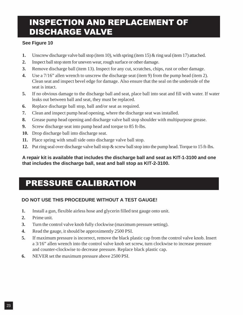
INSPECTION AND REPLACEMENT OFDISCHARGE VALVE
PRESSURE CALIBRATION
See Figure 10
1. Unscrew discharge valve ball stop (item 10), with spring (item 15) & ring seal (item 17) attached.2. Inspect ball stop stem for uneven wear, rough surface or other damage.3. Remove discharge ball (item 13). Inspect for any cut, scratches, chips, rust or other damage.4. Use a 7/16” allen wrench to unscrew the discharge seat (item 9) from the pump head (item 2).
Clean seat and inspect bevel edge for damage. Also ensure that the seal on the underside of theseat is intact.
5. If no obvious damage to the discharge ball and seat, place ball into seat and fill with water. If waterleaks out between ball and seat, they must be replaced.
6. Replace discharge ball stop, ball and/or seat as required.7. Clean and inspect pump head opening, where the discharge seat was installed.8. Grease pump head opening and discharge valve ball stop shoulder with multipurpose grease.9. Screw discharge seat into pump head and torque to 85 ft-lbs.10. Drop discharge ball into discharge seat.11. Place spring with small side onto discharge valve ball stop.12. Put ring seal over discharge valve ball stop & screw ball stop into the pump head. Torque to 15 ft-lbs.
A repair kit is available that includes the discharge ball and seat as KIT-1-3100 and onethat includes the discharge ball, seat and ball stop as KIT-2-3100.
DO NOT USE THIS PROCEDURE WITHOUT A TEST GAUGE!
1. Install a gun, flexible airless hose and glycerin filled test gauge onto unit.2. Prime unit.3. Turn the control valve knob fully clockwise (maximum pressure setting).4. Read the gauge, it should be approximently 2500 PSI.5. If maximum pressure is incorrect, remove the black plastic cap from the control valve knob. Insert
a 3/16” allen wrench into the control valve knob set screw, turn clockwise to increase pressureand counter-clockwise to decrease pressure. Replace black plastic cap.
6. NEVER set the maximum pressure above 2500 PSI.
23
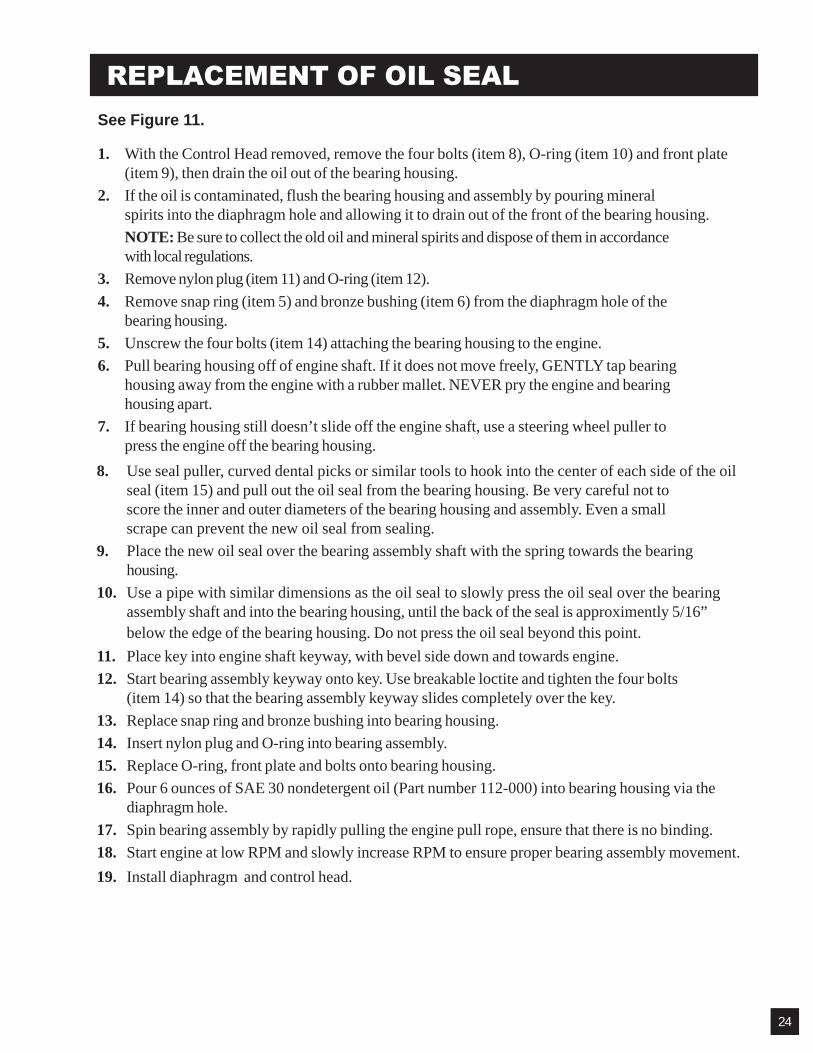
8. Use seal puller, curved dental picks or similar tools to hook into the center of each side of the oilseal (item 15) and pull out the oil seal from the bearing housing. Be very careful not toscore the inner and outer diameters of the bearing housing and assembly. Even a smallscrape can prevent the new oil seal from sealing.
9. Place the new oil seal over the bearing assembly shaft with the spring towards the bearinghousing.
10. Use a pipe with similar dimensions as the oil seal to slowly press the oil seal over the bearingassembly shaft and into the bearing housing, until the back of the seal is approximently 5/16”below the edge of the bearing housing. Do not press the oil seal beyond this point.
1. With the Control Head removed, remove the four bolts (item 8), O-ring (item 10) and front plate(item 9), then drain the oil out of the bearing housing.
2. If the oil is contaminated, flush the bearing housing and assembly by pouring mineralspirits into the diaphragm hole and allowing it to drain out of the front of the bearing housing.NOTE: Be sure to collect the old oil and mineral spirits and dispose of them in accordancewith local regulations.
3. Remove nylon plug (item 11) and O-ring (item 12).4. Remove snap ring (item 5) and bronze bushing (item 6) from the diaphragm hole of the
bearing housing.5. Unscrew the four bolts (item 14) attaching the bearing housing to the engine.6. Pull bearing housing off of engine shaft. If it does not move freely, GENTLY tap bearing
housing away from the engine with a rubber mallet. NEVER pry the engine and bearinghousing apart.
7. If bearing housing still doesn’t slide off the engine shaft, use a steering wheel puller topress the engine off the bearing housing.
REPLACEMENT OF OIL SEALSee Figure 11.
11. Place key into engine shaft keyway, with bevel side down and towards engine.12. Start bearing assembly keyway onto key. Use breakable loctite and tighten the four bolts
(item 14) so that the bearing assembly keyway slides completely over the key.13. Replace snap ring and bronze bushing into bearing housing.14. Insert nylon plug and O-ring into bearing assembly.15. Replace O-ring, front plate and bolts onto bearing housing.16. Pour 6 ounces of SAE 30 nondetergent oil (Part number 112-000) into bearing housing via the
diaphragm hole.17. Spin bearing assembly by rapidly pulling the engine pull rope, ensure that there is no binding.18. Start engine at low RPM and slowly increase RPM to ensure proper bearing assembly movement.19. Install diaphragm and control head.
24

PUMP HEAD ASSEMBLY - 115-101
123456789
115-101115-102115-105145-006115-107115-019115-022114-010115-004
Pump Head- Ass'yPump HeadSuction Seat Ass'ySeal WasherElbowFittingSuction Valve Ball 5/16"DiaSuction Valve Ball Stop *Discharge Valve Seat
10111213141516171819
115-007115-016115-017115-050115-024115-025115-027115-028115-031115-034
Discharge Valve Ball StopControl Valve SeatControl Ball 7/32" Dia.Discharge Ball 11/32" Dia.Pressure Control ValveSpring *ScrewRing SealT.C. GuidePlug
ITEM NO. PART NO. DESCRIPTION ITEM NO. PART NO. DESCRIPTION
FIGURE 10
* Not part of pump head assembly.
25

1 2 3 4*5*6*7*8
115-022115-025114-010114-001112-024112-006112-003112-009
Suction BallSpringSuction Ball StopDiaphragm (includes 2-3)
Snap RingBronze BushingBearing HousingScrew (4)
*9*10*11*12*13 14*15 16
Front PlateO-RingNylon PlugO-RingBearing Ass'yScrew (4)Oil SealKey (not shown)
112-007112-021112-052112-013139-070112-019139-039139-071
ITEM NO. PART NO. DESCRIPTION ITEM NO. PART NO. DESCRIPTION
FIGURE 11
BEARING HOUSE & DIAPHRAGM ASS'Y
17 139-038 Collar
*Complete Bearing House Part Number 139-043 (ITEMS *5,6,7,8,9,10,11,12,13 & 15)26
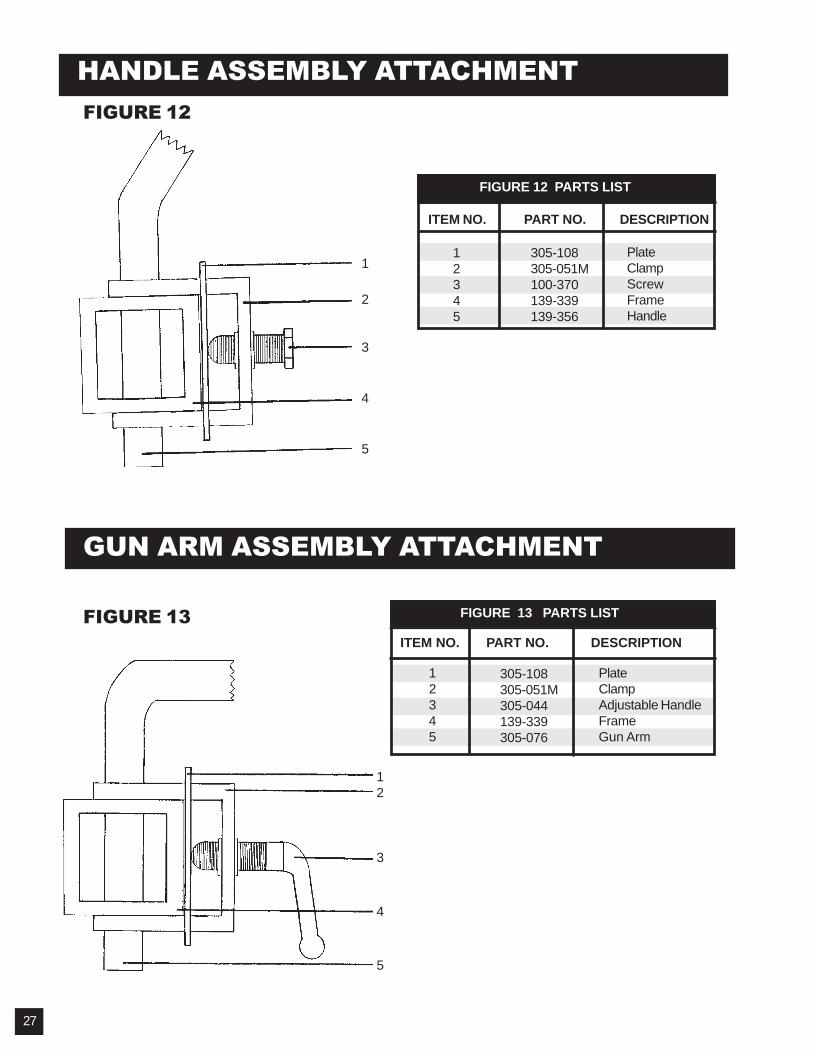
HANDLE ASSEMBLY ATTACHMENT
1
2
3
4
5
FIGURE 12 PARTS LIST
ITEM NO. PART NO. DESCRIPTION
12345
305-108305-051M100-370139-339139-356
GUN ARM ASSEMBLY ATTACHMENT
FIGURE 13 PARTS LIST
12345
305-108305-051M305-044139-339305-076
PlateClampAdjustable HandleFrameGun Arm
ITEM NO. PART NO. DESCRIPTION
12
3
4
5
FIGURE 12
FIGURE 13
PlateClampScrewFrameHandle
27

GUN ASSEMBLY - PN 305-167-99FIGURE 14
THROTTLE ASSEMBLYFIGURE 15
12345*
305-105136-023305-092-99136-136139-102
LeverCable End LugCable Ass'ySpringWasherPart of HandleEngine ThrottleLever
ITEM NO. PART NO. DESCRIPTION
FIGURE 15 PARTS LIST
28
(1) 136-218
(1) 305-150(1) 120-008
(1) 032-012
(1) 100-177(1) 120-000XL
(1) 032-028-55
561-029
(1) 561-002PART # DESCRIPTION PART # DESCRIPTION032-012 Gun Adapter032-028-55 Swivel Assembly100-177 90 Degree 1/4"120-000XL Basic 007 gun120-008 Tip Washer
136-218 Cable Guide305-150 Gun Holder Assembly561-002 Tip Guard561-029 Seal Kit for Tip Guard
ITEMNO.
PART NO. DESCRIPTIONITEMNO.
PART NO. DESCRIPTION
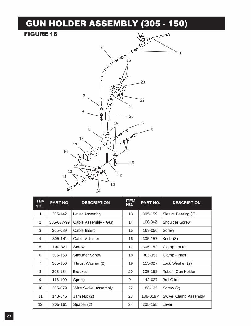
1 305-142 Lever Assembly 13 305-159 Sleeve Bearing (2)
2 305-077-99 Cable Assembly - Gun 14 305-160 Shoulder Screw
3 305-089 Cable Insert 15 169-050 Screw
4 305-141 Cable Adjuster 16 305-157 Knob (3)
5 100-321 Screw 17 305-152 Clamp - outer
6 305-158 Shoulder Screw 18 305-151 Clamp - inner
7 305-156 Thrust Washer (2) 19 113-027 Lock Washer (2)
8 305-154 Bracket 20 305-153 Tube - Gun Holder
9 116-100 Spring 21 143-027 Ball Glide
10 305-079 Wire Swivel Assembly 22 188-125 Screw (2)
11 140-045 Jam Nut (2) 23 136-019P Swivel Clamp Assembly
12 305-161 Spacer (2) 24 305-155 Lever
7
15
9
1617
18
12
3
420
2122
23
16
8
1413
11 12
10
19 56
GUN HOLDER ASSEMBLY (305 - 150)
24
FIGURE 16
ITEMNO.
PART NO. DESCRIPTION ITEMNO. PART NO. DESCRIPTION
29
100-342

FRAME ASSEMBLYFIGURE 17
30
2
3
410
11
12, 13, 14
15
16
17
26
1819
20,2122
23
24, 25, 2627
1
2
3
5
9
7, 84, 5, 6
1234567891011121314
305-150143-027139-353305-108305-051M100-370305-185100-373301-535139-356305-058305-138331-342120-021
Gun Holder Ass'yBall GuideArmPlate (2)Clamp (2)Screw (2)Brake Ass'yScrew (4)Rubber Pad (2)HandleRubber Grip (2)Cord Clamp (2)Screw (2)Nut (2)
1516171819202122232425262728
301-533119-026305-144143-029301-170112-058100-369301-165100-621305-108305-051M305-044139-360305-260
LidScrew (4)Bucket HolderSet Collar (2)AxleFlanged Bearing (2)Wave Washer (2)Wheel (2)Cap (4)PlateClampAdjustable HandleFrameRetrofit Kit
ITEMNO.
PART NO. DESCRIPTION ITEMNO.
PART NO. DESCRIPTION
28
SeeFigure 15
* 136-131 Chain* 100-011 1/4” x 50’ Airless Line
Not Shown

FIGURE 18
SWIVEL WHEEL ASSEMBLY - P.N. 305-260
SUCTION ASSEMBLY - P.N. 331-227FIGURE 19
31
100-318 Screw 5/16-18 x 3.75L100-393 Screw 6-32 x 2.0L100-394 Cap Screw 3/8 - 16x2.75L100-395 Cap Screw 3/8- 16 x 5.0L112-008 Flanged Bearing113-021 Cotter Pin119-035 Nut 3/8- 16136-223 Spring136-230 Axel 5/8 x 5.50L139-337A Wheel140-035 Washer .670 x .370140-053 Washer M18 x 3.0140-055 Washer .375 x 2.0143-029 Set Collar260-029 Castle Nut305-092 Cable Assembly305-105 Lever305-193 Spacer305-253 Swivel Clamp305-254 Swivel Frame305-255 Adjustment Sleeve305-256 Pivot Washer305-257 Swivel Lock Pin305-258 Swivel Lock305-259 End Lug305-261 Cable Holder