Embed Size (px)
Citation preview
TORNADO Technologies Inc. • 3236 - 50 Avenue SE, Calgary, Alberta, Canada T2B 3A3 • www.tornadotech.com
Tel: 403-244-3333 • Fax: 403-245-1821 • [email protected]
Sure Stop Detonation and Flame ArrestorsTechnical Data
Any ignition source (ie. flare or incinerator) creates an explosive opportunity for flame fronts to propogate back through lines, destroying facilities and causing injuries. An arrestor is a passive safety device designed to disperse a flame front, release its energy, and cool it to below the ignition point of that vapour. The following document will assist in choosing the correct arrestor for your application. Included are:
• Design Sheets
• General Dimensions & Weights
• Flow Capacity Curves
• DA Classifications
TORNADO Technologies Inc. • Tel: 403-244-3333 • Fax: 403-245-1821 • www.tornadotech.com
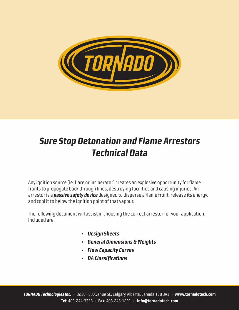
DESIGN INFORMATION
Type: � Detonation Arrestor � Inline Flame Arrestor � End-Of-Line Flame Arrestor
Installation: � Horizontal � Vertical � Other ° (angle)
Materials: Housing Element Housing Element
(Aluminum – 304L Stainless Steel – 316L Stainless Steel – Other)
Connections: Inlet Size: (NPT) Flange Pressure Rating: (ANSI 150 lb RF Standard)
Standard Detonation Arrestor confi guration comes with: 2 x Differential Pressure Ports
2 x Thermocouple Ports
2 x Drain Ports
Coating/Special Paint:
Additional Info:
PROCESS INFORMATION
* Please ensure details are complete and accurate so that our technical team can provide the best recommendation for product and installation.
Maximum Flow Rate: Inlet Pressure @ Max. Flow:
Normal Operating Flow: Normal Inlet Pressure:
Maximum Temperature: ° (C or F) Normal Operating Temperature: ° (C or F)
Molecular Weight/Specifi c Gravity: Does the stream have liquids? � Yes � No
NEC Gas Grouping: � A � B � C � D IEC Gas Grouping: � IIA � IIB � IIC
Gas/Vapor Composition (or complete page 2):
Desired Pressure Drop:
USCG Minimum Endurance Burn Protection: � Type 1 (2 hours) � Type 2 (15 minutes)
Distance of Installation From Potential Flame Source: Number of bends:
Additional Information:
Design Sheet – Page 1 of 2
Attention: Customer:
Company Name: General Location:
Phone: Project Reference:
Fax: Required By Date:
Email: Today’s Date:
Detonation and Flame ArrestorsDesign Sheet
TORNADO Technologies Inc. • Tel: 403-244-3333 • Fax: 403-245-1821 • www.tornadotech.com
Detonation and Flame ArrestorsDesign Sheet
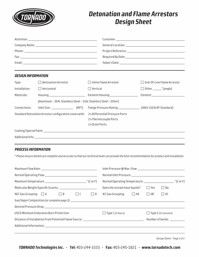
STREAM COMPOSITION
Component Mole Percent Mole Fraction
TOTALS:
LINE DIAGRAM* Please sketch layout as best as possible, including dimensions and distance from possible source of ignition.
Design Sheet – Page 2 of 2
TORNADO Technologies Inc. • 3236 - 50 Avenue SE, Calgary, Alberta, Canada T2B 3A3 • www.tornadotech.com
Tel: 403-244-3333 • Fax: 403-245-1821 • [email protected]
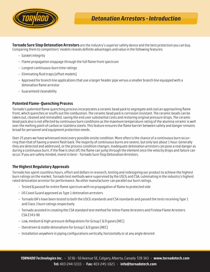
Tornado Sure Stop Detonation Arrestors are the industry’s superior safety device and the best protection you can buy. Comparing them to competitors’ models reveals defi nite advantages and value in the following features:
• Gasket integrity
• Flame propagation stoppage through the full fl ame front spectrum
• Longest continuous-burn time ratings
• Eliminating fl uid traps (offset models)
• Approved for branch line applications that use a larger header pipe versus a smaller branch line equipped with a detonation fl ame arrestor
• Guaranteed cleanability
Patented Flame–Quenching ProcessTornado’s patented fl ame quenching process incorporates a ceramic bead pack to segregate and cool an approaching fl ame front, which quenches or snuffs out the combustion. The ceramic bead pack is corrosion resistant. The ceramic beads can be taken out, cleaned and reinstalled, saving the end user substantial costs and restoring original pressure drops. The ceramic bead pack also is not affected by continuous burn conditions as the maximum temperature rating of the alumina ceramic is well over the melting point of carbon or stainless steels. This feature ensures the fl ame barrier between safety and danger remains broad for personnel and equipment protection needs.
Over 25 years we have witnessed most every possible onsite condition. More often is the chance of a continuous burn occur-ring than that of having a severe fl ash back. The majority of continuous burns are severe, but only last about 1 hour. Generally they are detected and addressed, or the process condition changes. Inadequate detonation arrestors can pose a real danger as during a continuous burn, if the fl ow is shut off, the fl ame can jump through the element once the velocity drops and failure can occur. If you are safety minded, invest in best – Tornado Sure Stop Detonation Arrestors.
The Highest Regulatory ApprovalsTornado has spent countless hours, effort and dollars in research, testing and redesigning our product to achieve the highest burn ratings on the market. Tornado test methods were supervised by the USCG and CSA, culminating in the industry’s highest rated detonation arrestor for performance. No other manufacturer can parallel our burn ratings.
• Tested & passed for entire fl ame spectrum with no propagation of fl ame to protected side
• US Coast Guard approved as Type 1 detonation arresters
• Tornado DA’s have been tested to both the USCG standards and CSA standards and passed the tests receiving Type 1 and Class 3 burn ratings respectively
• Tornado assisted in creating the CSA standard test method for Inline Flame Arresters and Firebox Flame Arresters CSA Z343-98
• Low, medium & high-pressure defl agrations for Group C & D gases (NEC)
• Overdriven & stable detonations for Group C & D gases (NEC)
• Installation anywhere in piping confi gurations vertically, horizontally or at any angle desired
Detonation Arrestors - Introduction
TORNADO Technologies Inc. • 3236 - 50 Avenue SE, Calgary, Alberta, Canada T2B 3A3 • www.tornadotech.com
Tel: 403-244-3333 • Fax: 403-245-1821 • [email protected]
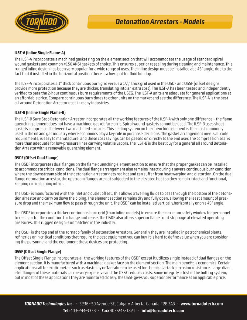
ILSF-A (Inline Single Flame-A)
The ILSF-A incorporates a machined gasket ring on the element section that will accommodate the usage of standard spiral wound gaskets and common #150 ANSI gaskets of choice. This ensures superior resealing during cleaning and maintenance. This rugged inline design has been very popular for a wide range of uses. The inline design must be installed at a 45° angle, due to the fact that if installed in the horizontal position there is a low spot for fl uid buildup.
The ILSF-A incorporates a 1” thick continuous burn grid versus a 11/2” thick grid used in the OSDF and OSSF (offset designs
provide more protection because they are thicker, translating into an extra cost). The ILSF-A has been tested and independently verifi ed to pass the 2-hour continuous burn requirements of the USCG. The ILSF-A units are adequate for general applications at an affordable price. Compare continuous burn times to other units on the market and see the difference. The ILSF-A is the best all-around Detonation Arrestor used in many industries.
ILSF-B (In line Single Flame-B)
The ILSF-B Sure Stop Detonation Arrestor incorporates all the working features of the ILSF-A with only one difference – the fl ame quenching element does not have a machined gasket face on it. Spiral wound gaskets cannot be used. The ILSF-B uses sheet gaskets compressed between two machined surfaces. This sealing system on the quenching element is the most commonly used in the oil and gas industry where economics play a key role in purchase decisions. The gasket arrangement meets all code requirements, is easy to manufacture, and these cost savings can be passed on directly to the end user. The compression seal is more than adequate for low-pressure lines carrying volatile vapors. The ILSF-B is the best buy for a general all around Detona-tion Arrestor with a removable quenching element.
OSDF (Offset Dual Flange)
The OSDF incorporates dual fl anges on the fl ame quenching element section to ensure that the proper gasket can be installed to accommodate critical conditions. The dual fl ange arrangement also remains intact during a severe continuous burn condition where the downstream side of the detonation arrestor gets red hot and can suffer from heat warping and distortion. On the dual fl ange detonation arrestor, the upstream fl anges are not subjected to the elevated heat so they remain intact and functional, keeping critical piping intact.
The OSDF is manufactured with the inlet and outlet offset. This allows travelling fl uids to pass through the bottom of the detona-tion arrestor and carry on down the piping. The element section remains dry and fully open, allowing the least amount of pres-sure drop and the maximum fl ow to pass through the unit. The OSDF can be installed vertically,horizontally or on a 45° angle.
The OSDF incorporates a thicker continuous burn grid (than inline models) to ensure the maximum safety window for personnel to react, or for the condition to change and cease. The OSDF also offers superior fl ame front stoppage at elevated operating pressures. This rugged design is unmatched in the industry.
The OSDF is the top end of the Tornado family of Detonation Arrestors. Generally they are installed in petrochemical plants, refi neries or in critical conditions that require the best equipment you can buy. It is hard to defi ne value when you are consider-ing the personnel and the equipment these devices are protecting.
OSSF (Offset Single Flange)
The Offset Single Flange incorporates all the working features of the OSDF except it utilizes single instead of dual fl anges on the element section. It is manufactured with a machined gasket face on the element section. The main benefi t is economics. Certain applications call for exotic metals such as Hastelloy or Tantalum to be used for chemical attack corrosion resistance. Large diam-eter fl anges of these materials can be very expensive and the OSSF reduces costs. Some integrity is lost in the bolting system, but in most of these applications they are monitored closely. The OSSF gives you superior performance at an applicable price.
Detonation Arrestors - Models
TORNADO Technologies Inc. • 3236 - 50 Avenue SE, Calgary, Alberta, Canada T2B 3A3 • www.tornadotech.com
Tel: 403-244-3333 • Fax: 403-245-1821 • [email protected]
Any technical data and the designs disclosed herein are the exclusive property of Tornado Technologies Inc. and/or contain the proprietary rights of others and are not to be used or disclosed to others without the written consent of Tornado Technologies Inc.
Detonation Arrestors (Inline)
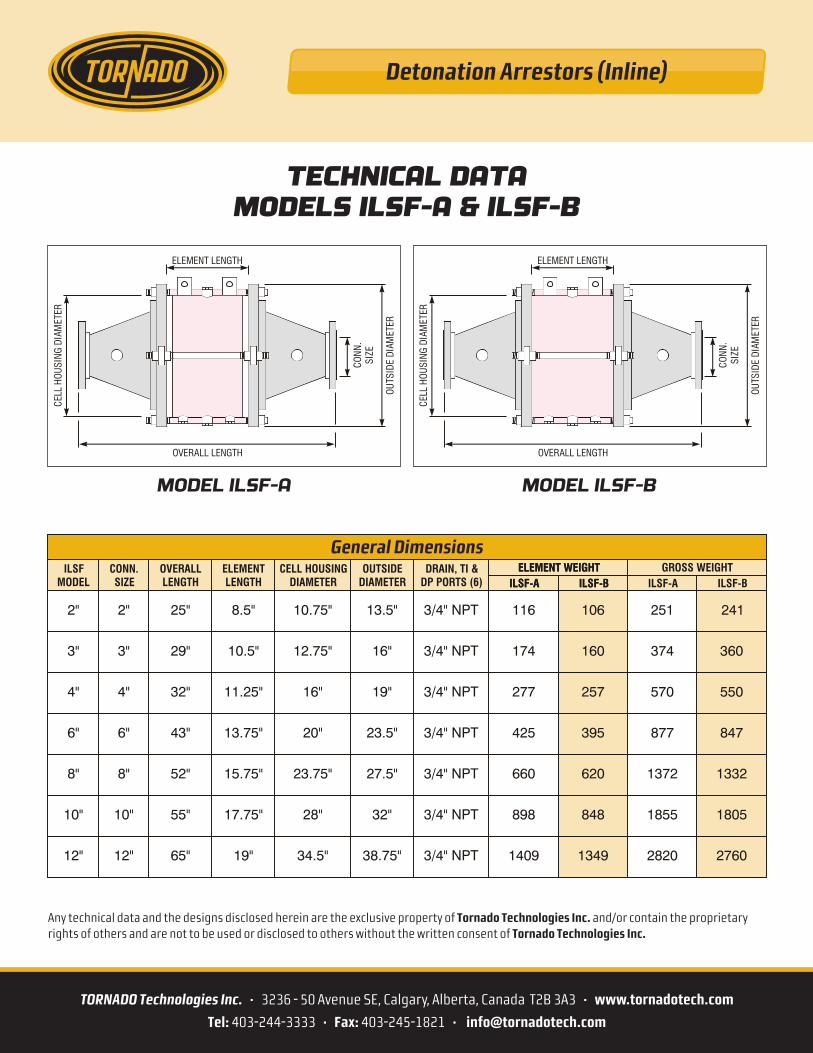
TECHNICAL DATAMODELS ILSF-A & ILSF-B
General DimensionsILSF
MODELCONN.SIZE
OVERALLLENGTH
ELEMENTLENGTH
CELL HOUSINGDIAMETER
OUTSIDEDIAMETER
DRAIN, TI &DP PORTS (6)
ELEMENT WEIGHTELEMENT WEIGHT GROSS WEIGHTILSF-A ILSF-AILSF-A ILSF-B ILSF-BILSF-B
2" 2" 25" 8.5" 10.75" 13.5" 3/4" NPT 116 106 251 241
3/4" NPT 174 160 374 360
3/4" NPT 277 257 570 550
3/4" NPT 425 395 877 847
3/4" NPT 660 620 1372 1332
3/4" NPT 898 848 1855 1805
3/4" NPT 1409 1349 2820 2760
3" 3" 29" 10.5" 12.75" 16"
4" 4" 32" 11.25" 16" 19"
6" 6" 43" 13.75" 20" 23.5"
8" 8" 52" 15.75" 23.75" 27.5"
10" 10" 55" 17.75" 28" 32"
12" 12" 65" 19" 34.5" 38.75"
MODEL ILSF-A MODEL ILSF-B
ELEMENT LENGTH
OVERALL LENGTH
OUTS
IDE
DIAM
ETE R
CON
N.
SIZE
CELL
HOUS
I NG
DIAM
E TER
ELEMENT LENGTH
OVERALL LENGTH
OUTS
IDE
DIAM
ETER
CON
N.
SIZE
CELL
HOUS
I NG
DIAM
E TER
Detonation Arrestors (Inline)
TORNADO Technologies Inc. • 3236 - 50 Avenue SE, Calgary, Alberta, Canada T2B 3A3 • www.tornadotech.com
Tel: 403-244-3333 • Fax: 403-245-1821 • [email protected]
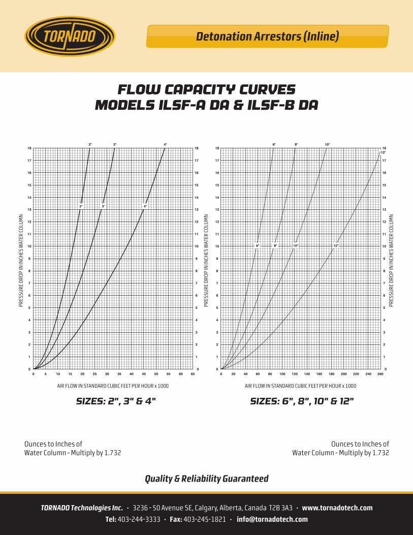
Ounces to Inches ofWater Column - Multiply by 1.732
Ounces to Inches ofWater Column - Multiply by 1.732
Quality & Reliability Guaranteed
12"
SIZES: 2", 3" & 4" SIZES: 6", 8", 10" & 12"
AIR FLOW IN STANDARD CUBIC FEET PER HOUR x 1000 AIR FLOW IN STANDARD CUBIC FEET PER HOUR x 1000
PRES
SURE
DRO
P IN
INCH
ES W
ATER
CO
LUM
N
PRES
SURE
DRO
P IN
INCH
ES W
ATER
CO
LUM
N
PRES
SURE
DRO
P IN
INCH
ES W
ATER
CO
LUM
N
18
17
16
15
14
13
12
11
10
9
8
7
6
5
4
3
2
1
00
18
17
16
15
14
13
12
11
10
9
8
7
6
5
4
3
2
1
05 10 15 20 25 3530 40 45 50 55 60 65
3" 4"2"
20 40 60 80 100 140120 160 180 200 220 240 260
18
17
16
15
14
13
12
11
10
9
8
7
6
5
4
3
2
1
00
18
17
16
15
14
13
12
11
10
9
8
7
6
5
4
3
2
1
0
8" 10"6"
8" 10"6" 12"
3"2"
FLOW CAPACITY CURVESMODELS ILSF-A DA & ILSF-B DA
4"
Detonation Arrestors (Offset)
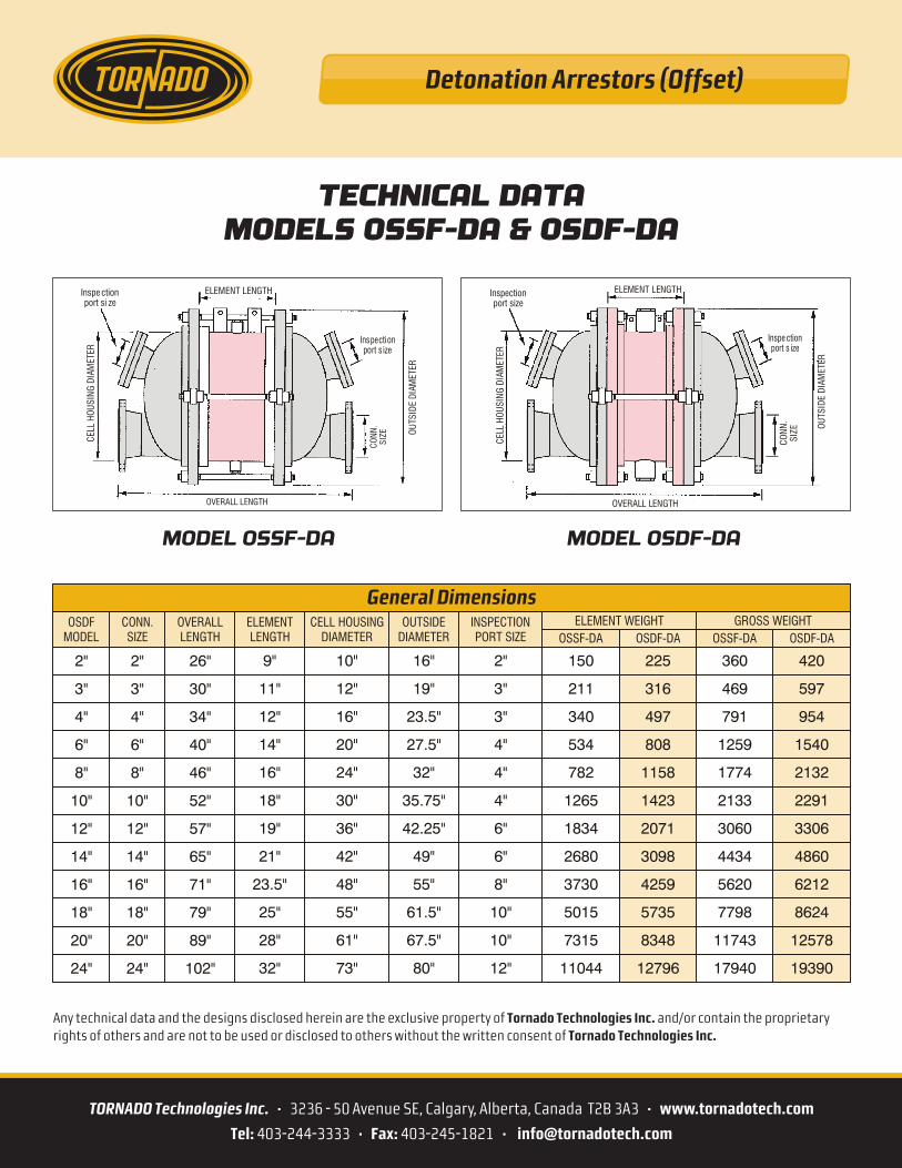
TECHNICAL DATAMODELS OSSF-DA & OSDF-DA
MODEL OSSF-DA MODEL OSDF-DA
TORNADO Technologies Inc. • 3236 - 50 Avenue SE, Calgary, Alberta, Canada T2B 3A3 • www.tornadotech.com
Tel: 403-244-3333 • Fax: 403-245-1821 • [email protected]
Any technical data and the designs disclosed herein are the exclusive property of Tornado Technologies Inc. and/or contain the proprietary rights of others and are not to be used or disclosed to others without the written consent of Tornado Technologies Inc.
General DimensionsOSDF
MODELCONN.SIZE
OVERALLLENGTH
ELEMENTLENGTH
CELL HOUSINGDIAMETER
OUTSIDEDIAMETER
INSPECTIONPORT SIZE
ELEMENT WEIGHT GROSS WEIGHTOSSF-DAOSSF-DA OSDF-DAOSDF-DA
2"
3"
4"
6"
8"
10"
12"
14"
16"
18"
20"
24"
2"
3"
4"
6"
8"
10"
12"
14"
16"
18"
20"
24"
26"
30"
34"
40"
46"
52"
57"
65"
71"
79"
89"
102"
9"
11"
12"
14"
16"
18"
19"
21"
23.5"
25"
28"
32"
10"
12"
16"
20"
24"
30"
36"
42"
48"
55"
61"
73"
16"
19"
23.5"
27.5"
32"
35.75"
42.25"
49"
55"
61.5"
67.5"
80"
2"
3"
3"
4"
4"
4"
6"
6"
8"
10"
10"
12"
150
211
340
534
782
1265
1834
2680
3730
5015
7315
11044
225
316
497
808
1158
1423
2071
3098
4259
5735
8348
12796
360
469
791
1259
1774
2133
3060
4434
5620
7798
11743
17940
420
597
954
1540
2132
2291
3306
4860
6212
8624
12578
19390
Inspectionport size
Inspe ctionport s ize
ELEMENT LENGTH
OVERALL LENGTH
OUTS
IDE
DIAM
ETER
CELL
HOUS
ING
DIAM
ETE R
CON
N.
SIZ E
Inspe ctionport si ze
Inspectionport s ize
ELEMENT LENGTH
OVERALL LENGTH
OUTS
IDE
DIAM
E TER
C ELL
HOUS
ING
DIA M
ETER
C ON
N.
S IZE

Detonation Arrestors (Offset)
TORNADO Technologies Inc. • 3236 - 50 Avenue SE, Calgary, Alberta, Canada T2B 3A3 • www.tornadotech.com
Tel: 403-244-3333 • Fax: 403-245-1821 • [email protected]
MODELS: 2", 3" & 4" MODELS: 6", 8" & 10"
AIR FLOW IN STANDARD CUBIC FEET PER HOUR x 1000 AIR FLOW IN STANDARD CUBIC FEET PER HOUR x 1000
PRES
SURE
DRO
P IN
INCH
ES W
ATER
CO
LUM
N
PRES
SURE
DRO
P IN
INCH
ES W
ATER
CO
LUM
N
PRES
SURE
DRO
P IN
INCH
ES W
ATER
CO
LUM
N
18
17
16
15
14
13
12
11
10
9
8
7
6
5
4
3
2
1
00
18
17
16
15
14
13
12
11
10
9
8
7
6
5
4
3
2
1
05 10 15 20 25 3530 40 45 50 55 60 65
3" 4"2"
20 40 60 80 100 140120 160 180 200 220 240 260
18
17
16
15
14
13
12
11
10
9
8
7
6
5
4
3
2
1
00
18
17
16
15
14
13
12
11
10
9
8
7
6
5
4
3
2
1
0
8" 10"6"
FLOW CAPACITY CURVESMODELS OSDF DA & OSSF DA
2" 3" 4" 8" 10"6"
Ounces to Inches ofWater Column - Multiply by 1.732
Ounces to Inches ofWater Column - Multiply by 1.732
Quality & Reliability Guaranteed
Detonation Arrestors (Offset)
TORNADO Technologies Inc. • 3236 - 50 Avenue SE, Calgary, Alberta, Canada T2B 3A3 • www.tornadotech.com
Tel: 403-244-3333 • Fax: 403-245-1821 • [email protected]
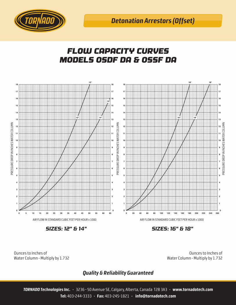
SIZES: 12" & 14" SIZES: 16" & 18"
AIR FLOW IN STANDARD CUBIC FEET PER HOUR x 1000 AIR FLOW IN STANDARD CUBIC FEET PER HOUR x 1000
PRES
SURE
DRO
P IN
INCH
ES W
ATER
CO
LUM
N
PRES
SURE
DRO
P IN
INCH
ES W
ATER
CO
LUM
N
PRES
SURE
DRO
P IN
INCH
ES W
ATER
CO
LUM
N
18
17
16
15
14
13
12
11
10
9
8
7
6
5
4
3
2
1
00
18
17
16
15
14
13
12
11
10
9
8
7
6
5
4
3
2
1
05 10 15 20 25 3530 40 45 50 55 60 65
12"
20 40 60 80 100 140120 160 180 200 220 240 260
18
17
16
15
14
13
12
11
10
9
8
7
6
5
4
3
2
1
00
18
17
16
15
14
13
12
11
10
9
8
7
6
5
4
3
2
1
0
18"16"
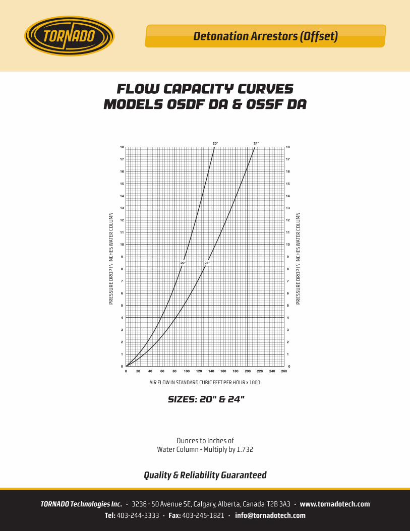
FLOW CAPACITY CURVESMODELS OSDF DA & OSSF DA
12" 14"
14"
18"16"
Ounces to Inches ofWater Column - Multiply by 1.732
Ounces to Inches ofWater Column - Multiply by 1.732
Quality & Reliability Guaranteed
Detonation Arrestors (Offset)
TORNADO Technologies Inc. • 3236 - 50 Avenue SE, Calgary, Alberta, Canada T2B 3A3 • www.tornadotech.com
Tel: 403-244-3333 • Fax: 403-245-1821 • [email protected]
SIZES: 20" & 24"
AIR FLOW IN STANDARD CUBIC FEET PER HOUR x 1000
PRES
SURE
DRO
P IN
INCH
ES W
ATER
CO
LUM
N
PRES
SURE
DRO
P IN
INCH
ES W
ATER
CO
LUM
N
20 40 60 80 100 140120 160 180 200 220 240 260
18
17
16
15
14
13
12
11
10
9
8
7
6
5
4
3
2
1
00
18
17
16
15
14
13
12
11
10
9
8
7
6
5
4
3
2
1
0
24"20"
FLOW CAPACITY CURVESMODELS OSDF DA & OSSF DA
24"20"
Ounces to Inches ofWater Column - Multiply by 1.732
Quality & Reliability Guaranteed
TORNADO Technologies Inc. • 3236 - 50 Avenue SE, Calgary, Alberta, Canada T2B 3A3 • www.tornadotech.com
Tel: 403-244-3333 • Fax: 403-245-1821 • [email protected]
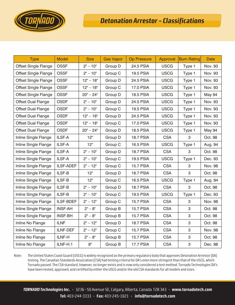
Note: The United States Coast Guard (USCG) is widely recognized as the primary regulatory body that approves Detonation Arrestor (DA) testing. The Canadian Standards Association (CSA) had testing criteria for DA’s even more stringent than that of the USCG, which Tornado passed. The CSA standard, however, no longer exists and is now only considered a test method. Tornado Technologies DA’s have been tested, approved, and certified by either the USCG and/or the old CSA standards for all models and sizes.
Detonation Arrestor – Classifications
Type Model Size Gas Vapor Op Pressure Approval Burn Rating Date
Offset Single Flange OSSF 2" – 10" Group D 24.5 PSIA USCG Type 1 Nov. 93
Offset Single Flange OSSF 2" – 10" Group C 19.5 PSIA USCG Type 1 Nov. 93
Offset Single Flange OSSF 12" – 18" Group D 24.5 PSIA USCG Type 1 Nov. 93
Offset Single Flange OSSF 12" – 18" Group C 17.0 PSIA USCG Type 1 Nov. 93
Offset Single Flange OSSF 20" – 24" Group D 18.5 PSIA USCG Type 1 May 94
Offset Dual Flange OSDF 2" – 10" Group D 24.5 PSIA USCG Type 1 Nov. 93
Offset Dual Flange OSDF 2" – 10" Group C 19.5 PSIA USCG Type 1 Nov. 93
Offset Dual Flange OSDF 12" – 18" Group D 24.5 PSIA USCG Type 1 Nov. 93
Offset Dual Flange OSDF 12" – 18" Group C 17.0 PSIA USCG Type 1 Nov. 93
Offset Dual Flange OSDF 20" – 24" Group D 18.5 PSIA USCG Type 1 May 94
Inline Single Flange ILSF-A 12" Group D 18.7 PSIA CSA 3 Oct. 98
Inline Single Flange ILSF-A 12" Group C 16.5 PSIA USCG Type 1 Aug. 94
Inline Single Flange ILSF-A 2" – 10" Group D 18.7 PSIA CSA 3 Oct. 98
Inline Single Flange ILSF-A 2" – 10" Group C 19.5 PSIA USCG Type 1 Dec. 93
Inline Single Flange ILSF-ADEF 2" – 12" Group C 15.7 PSIA CSA 3 Nov. 98
Inline Single Flange ILSF-B 12" Group D 18.7 PSIA CSA 3 Oct. 98
Inline Single Flange ILSF-B 12" Group C 16.5 PSIA USCG Type 1 Aug. 94
Inline Single Flange ILSF-B 2" – 10" Group D 18.7 PSIA CSA 3 Oct. 98
Inline Single Flange ILSF-B 2" – 10" Group C 19.5 PSIA USCG Type 1 Dec. 93
Inline Single Flange ILSF-BDEF 2" – 12" Group C 15.7 PSIA CSA 3 Nov. 98
Inline Single Flange INSF-AH 2" – 8" Group B 15.7 PSIA CSA 3 Oct. 98
Inline Single Flange INSF-BH 2" – 8" Group B 15.7 PSIA CSA 3 Oct. 98
Inline No Flange ILNF 2" – 12" Group D 18.7 PSIA CSA 3 Oct. 98
Inline No Flange ILNF-DEF 2" – 12" Group C 15.7 PSIA CSA 3 Nov. 98
Inline No Flange ILNF-H 2" – 8" Group B 15.7 PSIA CSA 3 Oct. 98
Inline No Flange ILNF-H.1 8" Group B 17.7 PSIA CSA 3 Dec. 98
TORNADO Technologies Inc. • 3236 - 50 Avenue SE, Calgary, Alberta, Canada T2B 3A3 • www.tornadotech.com
Tel: 403-244-3333 • Fax: 403-245-1821 • [email protected]
Flame Arrestor (Crimped Ribbon)
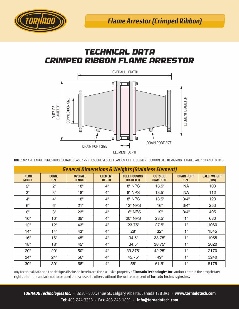
TECHNICAL DATACRIMPED RIBBON FLAME ARRESTOR
General Dimensions & Weights (Stainless Element)INLINEMODEL
CONN.SIZE
OVERALLLENGTH
ELEMENTDEPTH
CELL HOUSINGDIAMETER
OUTSIDEDIAMETER
DRAIN PORTSIZE
CALC. WEIGHT(LBS)
2"
3"
4"
6"
8"
10"
12"
14"
16"
18"
20"
24"
30"
2"
3"
4"
6"
8"
10"
12"
14"
16"
18"
20"
24"
30"
18"
18"
18"
21"
23"
35"
43"
43"
45"
45"
50"
56"
68"
4"
4"
4"
4"
4"
4"
4"
4"
4"
4"
4"
4"
4"
8" NPS
8" NPS
8" NPS
12" NPS
16" NPS
20" NPS
23.75"
28"
34.5"
34.5"
39.375"
45.75"
58"
13.5"
13.5"
13.5"
16"
19"
23.5"
27.5"
32"
38.75"
38.75"
42.25"
49"
61.5"
NA
NA
3/4"
3/4"
3/4"
1"
1"
1"
1"
1"
1"
1"
1"
103
112
123
253
405
680
1060
1545
1965
2020
2170
3240
5175
OUTS
IDE
DIAM
ETER
ELEM
ENT
DIAM
ETER
CONN
ECTI
ON S
IZE
DRAIN PORT SIZEDRAIN PORT SIZE
ELEMENT DEPTH
OVERALL LENGTH
NOTE: 16" AND LARGER SIZES INCORPORATE CLASS 175 PRESSURE VESSEL FLANGES AT THE ELEMENT SECTION. ALL REMAINING FLANGES ARE 150 ANSI RATING.
Any technical data and the designs disclosed herein are the exclusive property of Tornado Technologies Inc. and/or contain the proprietary rights of others and are not to be used or disclosed to others without the written consent of Tornado Technologies Inc.
Flame Arrestor (Crimped Ribbon)
TORNADO Technologies Inc. • 3236 - 50 Avenue SE, Calgary, Alberta, Canada T2B 3A3 • www.tornadotech.com
Tel: 403-244-3333 • Fax: 403-245-1821 • [email protected]
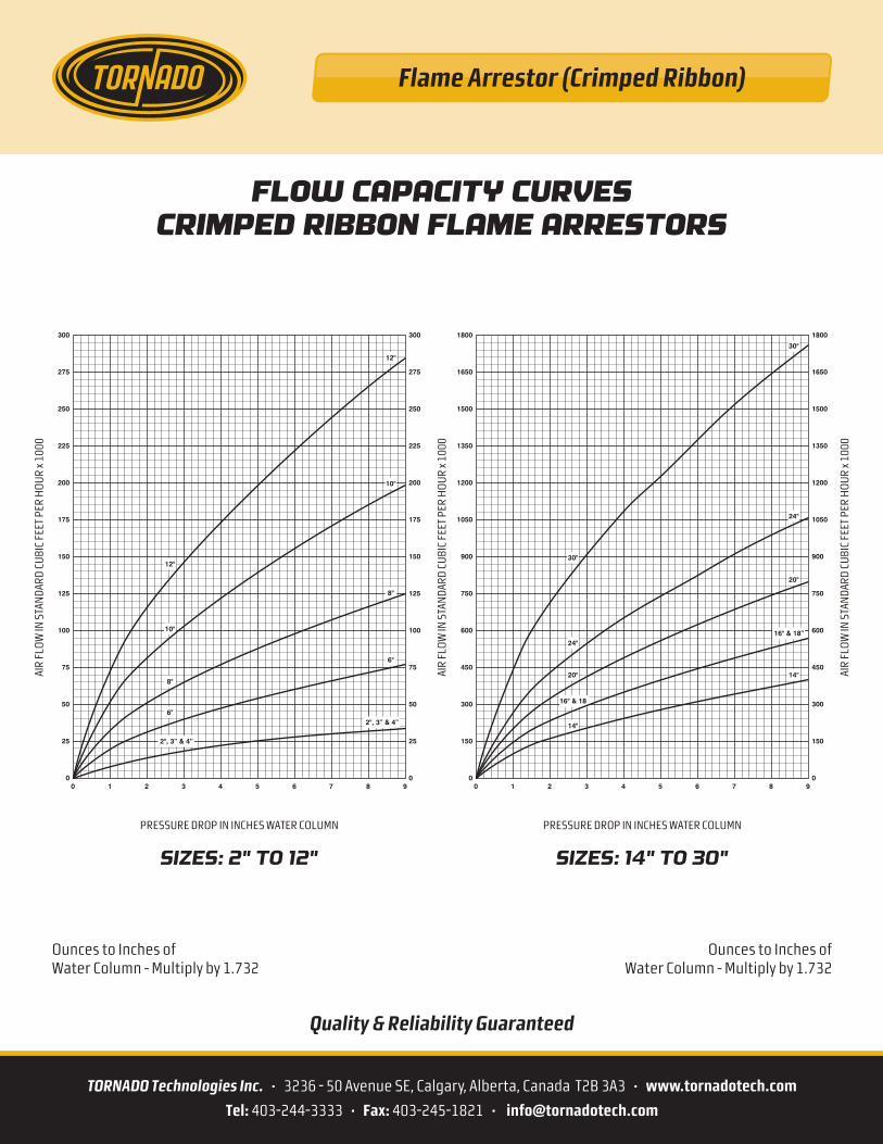
SIZES: 2" TO 12" SIZES: 14" TO 30"
PRESSURE DROP IN INCHES WATER COLUMN PRESSURE DROP IN INCHES WATER COLUMN
AIR
FLO
W IN
STA
ND
ARD
CU
BIC
FEET
PER
HO
UR
x 100
0
AIR
FLO
W IN
STA
ND
ARD
CU
BIC
FEET
PER
HO
UR
x 100
0
AIR
FLO
W IN
STA
ND
ARD
CU
BIC
FEET
PER
HO
UR
x 100
0
0
25
50
75
100
125
150
175
200
225
250
275
300
0
25
50
75
100
125
150
175
200
225
250
275
300
0 1 2 3 4 5 6 7 8 9
FLOW CAPACITY CURVESCRIMPED RIBBON FLAME ARRESTORS
12"
10"
8"
6"
6"
8"
10"
12"
2", 3” & 4”
2", 3” & 4”
0
150
300
450
600
750
900
1050
1200
1350
1500
1650
1800
0
150
300
450
600
750
900
1050
1200
1350
1500
1650
1800
0 1 2 3 4 5 6 7 8 9
30"
24"
20"
14"
16" & 18
14"
16" & 18”
20"
24"
30"
Ounces to Inches ofWater Column - Multiply by 1.732
Ounces to Inches ofWater Column - Multiply by 1.732
Quality & Reliability Guaranteed


![Flame Visualization and Mechanism of Fast Flame ... · gas infrared burners, fuel-reforming reactors and also flame arrestors [1, 2]. For sophisticated design and safe operation of](https://img.pdfslide.us/doc/110x75/5f0fa8227e708231d4453e46/flame-visualization-and-mechanism-of-fast-flame-gas-infrared-burners-fuel-reforming.jpg)