Embed Size (px)
Citation preview
TRANSACTIONS PAPER
SUPPLY-POLLUTION (SP) LOSS IN INDUCTION MOTOR
by John S. Hsu for the Oak Ridge National Laboratory pc [+ j i f ::;- ;d
July 1995
Issued by Lockheed Martin Energy Systems
The submitted manuscript has been authored by Oak Ridge National Laboratory, Oak Ridge, Tennessee 3783 1, managed by Lock Martin Energy Systems for the US. Department of Energy under contract No. DE-AC05-840R21400. Accordingly, the U.S. Government retains a nonexclusive, royalty-fiee license to publish or reproduce the published form of this contribution, or allow others to do so, for U.S. Government purposes.
Prepared by the Oak Ridge National Laboratory managed by LOCKHEED MARTIN ENERGY SYSTEMS for the U.S. DEPARTMENT OF ENERGY under contract DE-AC05-84)R21400.
Supply-Pollution (SP) Loss in Induction Motor John S. Hsu (Htsui)
Oak Ridge National Laboratory Post Office Box 2003, K-1008-F, MS 7258
Oak Ridge, Tennessee 37831-7258
Abstract: Power supply in the field is often noticeably polluted with various degrees of harmonics content and unbalanced voltages. In order to assess the energy loss caused by the supply pollution in the widely used induction motors, a method based on the air-gap torque power is discussed.
I. INTRODUCTION
Induction motors are the most commonly used motors. Ideally, the power supply for induction motors in the field should be balanced and without harmonics. In reality, it is not uncommon to notice that the supply is often polluted with various degrees of harmonics content and unbalanced voltages. The pollution may come from the power system and from the polluting loads within the plant, where some loads may not be balanced, or certain power electronics loads may not have proper filters to prevent their polluting the power supply.
The Project IEEE-519 [l] gives the IEEE recommended practices and requirements for harmonic control in electric power systems. It is a good resource to understand the power system pollution issue. It recommends the voltage distortion limits for a bus voltage 69 KV and below at PCC (point of common coupling with the consumer-utility interface) are 3.0% for the individual voltage distortion, and 5.0% for the total voltage distortion THD (total harmonic voltage distortion). The National Electrical Manufacturers Association (NEMA) standard [2] specifies the limits of variations from rated voltage and rated frequency. They are 210% of rated voltage with rated frequency, or 25% of rated frequency with rated voltage. The voltage unbalance at the motor terminals is limited to 1.0%. The IEEE 112 Standard [3] for the testing of polyphase induction motors specifies a narrower limit than that of the NEMA Standard [2] for the supply tolerance.
It is generally agreeable that the supply pollution results in energy loss in induction motors. Consequently, the motors run at a higher temperature with a shorter life expectancy, the user pays a higher electricity bill, and the public faces a stronger green house effect. However, this qualitative awareness must be further judged through a quantitative assessment of loss in induction motors caused by the power source pollution. This study serves this purpose by suggesting an assessment method through the air-gap torque.
In this information era, digital data acquisition techniques become accessible for those who can afford a personal computer, and the data acquisition cards added inside the computer. There are other more sophisticated data acquisition devices, such as the multiple channel digital storage oscilloscopes, available on the market. Through the data acquisition, the waveforms of terminal voltages and currents of an induction motor serving in the field cari be obtained. From these waveforms many analyses can be performed. This paper uses the similar data acquisition setup described in [4].
It should be noted that when the supply is polluted, the current and voltage waveforms of a cycle are not necessarily the same as their waveforms in an adjacent cycle. Therefore, for better accuracy, multiple cycles should be used for the supply pollution (SP) loss assessment.
This study identifies the useful torques that produce output power. The total input power from the supply, the fundamental positive-sequence stator copper loss, and the resultant synchronous air-gap torque power are used to assess the SP loss. It is an additional loss of the induction motor serving in the polluted field.
An earlier paper [4] that uses the air-gap torque to assess motor efficiency may have hidden a similar topic in its evaluation process. However, the supply pollution warrants a standalone discussion to focus on its damage in terms of loss and its assessment without going into the entire efficiency evaluation. This paper refers the relevant information to the reference to avoid repetition.
When an induction motor is fed by an inverter that may produce a certain content of harmonics, the same SP loss
1
assessment described in this paper can be used.
The SP losses were computed for several experimental motors that range from five to a hundred horsepower. Experimental results indicate that this loss cannot be ignored when induction motors are operating in the field.
II. Supply-Pollution Loss
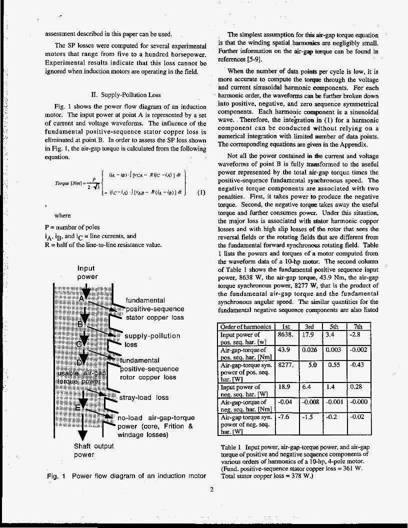
Fig. 1 shows the power flow diagram of an induction motor. The input power at point A is represented by a set of current and voltage waveforms. The influence of the fundamental positive-sequence stator copper loss is eliminated at point B. In order to assess the SP loss shown in Fig. 1, the air-gap torque is calculated from the following equation.
9
where
P = number of poles iA, ig, and i c = line currents, and R = half of the line-to-line resistance value.
Input power
positive-sequence stator copper loss
supply-pollution
o-load air-gap-torque ower (core, Frition &
Shaft output power
Fig. 1 Power flow diagram of an induction motor
The simplest assumption for this +-gap torque equation is that the winding spatial harmonics are negligibly small. Further information on the air-gap =que can be found in references [5-91.
When the number of data points per cycle is low, it is more accurate to compute the torque through the voltage and current sinusoidal harmonic csanponents. For each harmonic order, the waveforms can be further broken down into positive, negative, and zero sequence symmetrical components. Each harmonic component is a sinusoidal wave. Therefore, the inteiration in (1) for a harmonic component can be conducted without relying on a numerical integration with limited number of data points. The corresponding equations are given in the Appendix.
Not all the power contained in the current and voltage waveforms of point B is fully transformed to the useful power represented by the total air-gap torque times the positive-sequence fundamental synchronous speed. The negative torque components are associated with two penalties. First, it takes power to produce the negative torque. Second, the negative torque takes away the useful torque and further consumes power. Under this situation, the major loss is associated with stator harmonic copper losses and with high slip losses of the rotor that sees the reversal fields or the rotating fields that are different from the fundamental forward synchronous rotating field. Table 1 lists the powers and torques of a motor computed from the waveform data of a 10-hp motor. The second column of Table 1 shows the fundamental positive sequence input power, 8638 W, the air-gap torque- 43.9 Nm, the air-gap torque synchronous power, 8277 W, that is the product of the fundamental air-gap torque and the fundamental synchronous angular speed. The similar quantities for the fundamental negative sequence components are also listed
Order of harmonics Input power of pos. seq. har. [wl Air-gaptorque of pos. seq. har. [Nml Air-gap-torque syn. power of pos. seq. har. ywl Input power of neg. seq. har. [Wl Air-gap-torque of neg. seq. har. INml Air-gap torque syn. power of neg. seq. har. ywl
1 st 8638.
43.9
8277.
- -
18.9
-0.04
-7.6
- -
0.026 0.003 -0.002
0.55 -0.43
-0.008 -0.001 -0.000
-0.2 -0.02
Table 1 Input power, air-gap-torque power, and air-gap torque of positive and negative sequence components of various orders of harmonics of a Whp, 4-pole motor. (Fund. positive-sequence stator copper loss = 361 W. Total stator copper loss = 378 W.)
2
in the second column. They are 18.9 W for the fundamental negative sequence input power, -0.04 Nm for its air-gap torque, and -7.6 W for the air-gap torque synchronous power. All the synchronous powers in this table are referring to the fundamental positive-sequence synchronous speed, that is not the harmonic synchronous speed. The negative sequence torque rotates at the reversal synchronous speed. The negative torque not only requires 18.9 W to be produced but also takes away 7.6 W from the useful torque power. The total SP loss for the fundamental frequency is 18.9+7.6=26.5 W.
The third column of Table 1 gives the quantities of the same items as those in column 2. In a balanced supply the third harmonic phase currents are zero-sequence currents that do not produce torque. However, when the power is not symmetrically balanced, the third-harmonic components are not necessarily all zero sequence quantities.
From the energy standpoint, the SP loss is the input power less the fundamental positive-sequence stator copper loss, and minus the air-gap power that includes the no-load losses at the positive-sequence fundamental synchronous speed.
SP Loss= nput power - Fund. pos. seq. stator copper loss) [" - (A i r gap torque power at synchronous speed)
As an example: The input power is the sum of the input powers of all the harmonics including the fundamental. From Table 1 the input power = 8638 + 17.9 + 3.4 - 2.8 + 18.9 + 6.4 + 1.4 + 0.28 = 8683 W. The air-gap torque power at the fundamental synchronous speed is 8277 + 5 +
Substituting the numbers, 8683 W, 8273 W, and the 361 W of the fundamental positive-sequence stator copper loss into (2) gives the SP loss = 49 W for the sample motor.
Alternatively, from an energy standpoint the total SP loss can also be obtained by adding up all the harmonics input powers less their useful torque powers given in Table 1. The SP loss is (17.9-5) + (3.4-0.55) + (-2.8 + 0.43) + (18.9+7.6) + (641-1.5) + (1.44.2) + (0.28+0.02))= 49.7 W. The slight discrepancy from the 49 W is caused by the rounding up each item in the computation. A 49 W SP loss is approximately 0.7% of the 10-hp rating.
The power at point D is derived from point C by taking out the fundamental rotor copper loss that is roughly represented by the slip corresponding to the positive- sequence fundamental synchronous speed. The power at Point D includes the output power and the additional stray-
0.55 - 0.43 - 7.6 - 1.5 - 0.2 - 0.02 = 8273 W.
load loss. It also includes the core loss, friction and windage loss that are represented by the no load air-gap torque power.
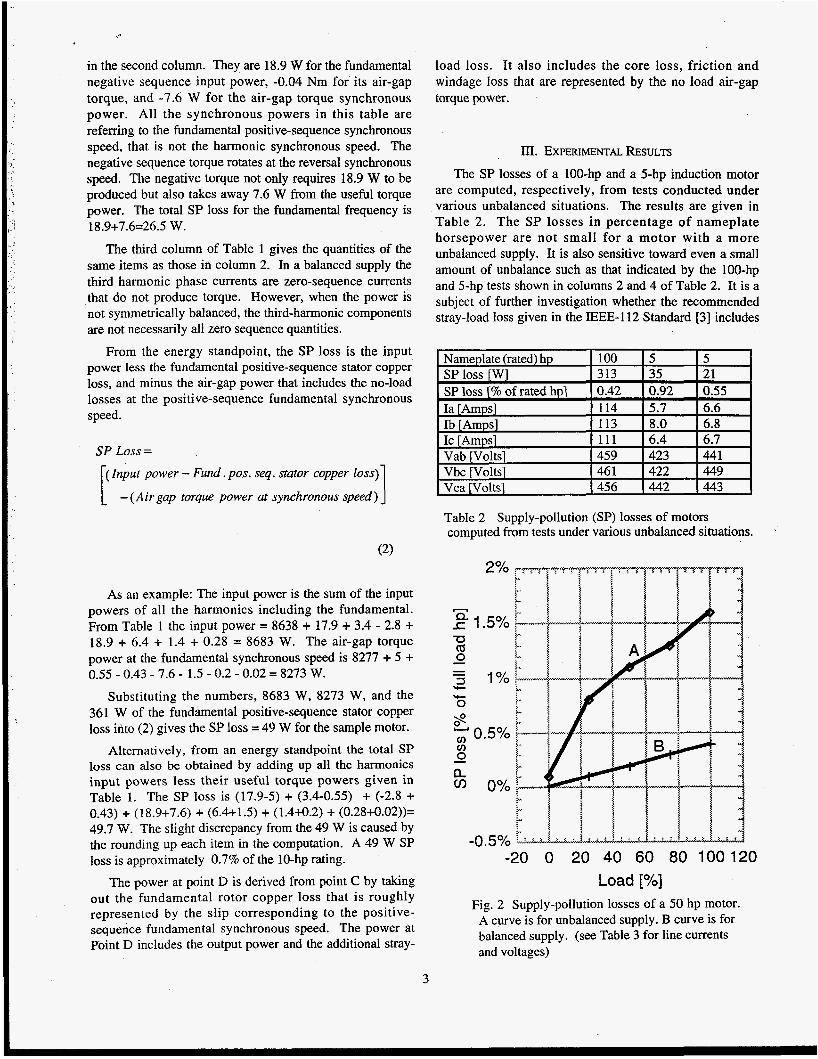
III. EXPERIMENTAL RESULTS The SP losses of a 100-hp and a 5-hp induction motor
are computed, respectively, from tests conducted under various unbalanced situations. The results are given in Table 2. The SP losses in percentage of nameplate horsepower are not small for a motor with a more unbalanced supply. It is also sensitive toward even a small amount of unbalance such as that indicated by the 100-hp and 5-hp tests shown in columns 2 and 4 of Table 2. It is a subject of further investigation whether the recommended stray-load loss given in the IEEE-112 Standard [3] includes
I Nameplate (rated) hp I
Table 2 Supply-pollution (SP) losses of motors computed from tests under various unbalanced situations. ~
-0.5% -20 0 20 40 60 80 100 120
Load E"/.] Fig. 2 Supply-pollution losses of a 50 hp motor.
A curve is for unbalanced supply. B curve is for balanced supply. (see Table 3 for line currents and voltages)
3
VI. ACKNOWLEDGMENTS
would like to thank the Office of Energy Renewable Energy, U.S. Department of , for partial financial support through the
Motor Challenge Program. Thanks are due to the Oak Ridge National Laboratory (ORNL) for the support staff and facilities provided for the research work. The author would like to express his appreciation to Paul Scheihing, DOE program manager, Mitchell Olszewski, ORNL program manager, and Donald Adams, group manager, for their support in this research as well. Appreciation is also extended to Donald Casada, John Kueck, Pedro Otaduy, and Leon Tolbert for their test data conducted on induction motors on which the author based his calculation, and for their suggestion of looking into multiple cycles of data obtained in the field.
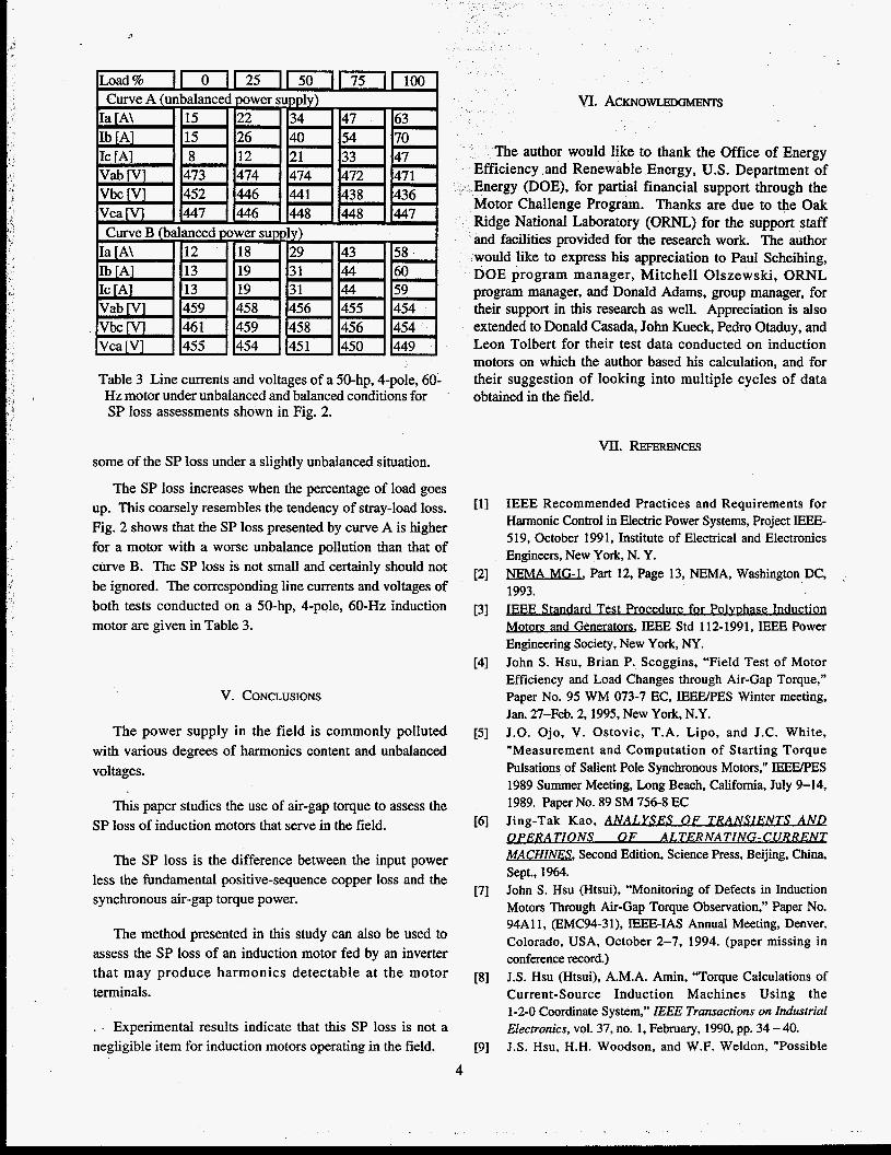
Table 3 Line currents and voltages of a 50-hp, 4-pole, 60- Hz motor under unbalanced and balanced conditions for SP loss assessments shown in Fig. 2.
some of the SP loss under a slightly unbalanced situation.
The SP loss increases when the percentage of load goes up. This coarsely resembles the tendency of stray-load loss. Fig. 2 shows that the SP loss presented by curve A is higher for a motor with a worse unbalance pollution than that of curve B. The SP loss is not small and certainly should not be ignored. The corresponding line currents and voltages of both tests conducted on a 50-hp, 4-pole, 6O-Hz induction motor are given in Table 3.
V. CONCLUSIONS
The power supply in the field is commonly polluted with various degrees of harmonics content and unbalanced voltages.
This paper studies the use of air-gap torque to assess the SP loss of induction motors that serve in the field.
The SP loss is the difference between the input power less the fundamental positive-sequence copper loss and the synchronous air-gap torque power.
The method presented in this study can also be used to assess the SP loss of an induction motor fed by an inverter that may produce harmonics detectable at the motor terminals.
. - Experimental results indicate that this SP loss is not a negligible item for induction motors operating in the field.
4
W. REFERENCES
IEEE Recommended Practices and Requirements for Harmonic Control in Electric Power Systems, Project IEEE- 519, October 1991, Institute of Electrical and Electronics Engineers, New York, N. Y. NEMA MG-1, Part 12, Page 13, NEMA, Washington DC, 1993. BEE Stands rd Test Procedu re for Polvphase Induction Motors and Generam, IEEE Std 112-1991, IEEE Power Engineering Society, New York, NY. John S. Hsu, Brian P. Scoggins, “Field Test of Motor Efficiency and Load Changes through Air-Gap Torque,” Paper No. 95 WM 073-7 EC, IEEEPES Winter meeting, Jan. 27-Feb. 2,1995, New York, N.Y. J.O. Ojo, V. Ostovic, T.A. Lipo, and J.C. White, ”Measurement and Computation of Starting Torque Pulsations of Salient Pole Synchronous Motors,” IEEIYPES 1989 Summer Meeting, Long Beach, California, July 9-14, 1989. Paper No. 89 SM 756-8 EC Jing-Tak Kao, ANAI.YSES O F TRANSIENTS A N D O P E R A T I O N S OF A L T E R N A T I N G - C U R R EN T MACHINES, Second Edition, Science Press, Beijing, China, Sept., 1964. John S. Hsu (Htsui), “Monitoring of Defects in Induction Motors Through Air-Gap Torque Observation,” Paper No. 94A11, (EMC94-3 I), IEEE-IAS Annual Meeting, Denver, Colorado, USA, October 2-7, 1994. (paper missing in conference record.) J.S. Hsu (Htsui), A.M.A. Amin, “Torque Calculations of Current-Source Induction Machines Using the 1-2-0 Coordinate System,” IEEE Transactions on Industrial Electronics, vol. 37, no. 1, February, 1990, pp. 34 - 40. J.S. Hsu, H.H. Woodson, and W.F. Weldon, “Possible
-Errors in Measurement of Air-Gap Torque Pulsations of Induction Motors,” IEEE Transactions on Energy Conversion , (Paper NO. 91 SM 390-5 EC)
[lo] John S. Hsu, Pedro J. Otaduy, John D. Kueck, “Efficiency and Reliability Assessments of Retrofitted High-Efficiency Motors,” IASIIEEE Annual Meeting, Orlando, Flordia, October 8-12,1995.
[l 1 J Hsu, J. S., Liou, S. P., Lin, B. T., Weldon, W. F., “Losses Influence by Third-Harmonic Flux in Induction Motor,” IEEE Transactions on Energy Conversion, Paper No. 91 Wh4 057-0 EC.
VIn. APPENDIX: POSITIVE AND NEGATIVE-SEQUENCE VOLTAGE AND CURRENT HARMONICS AND AIR-GAP TORQUE
COMPONENTS.
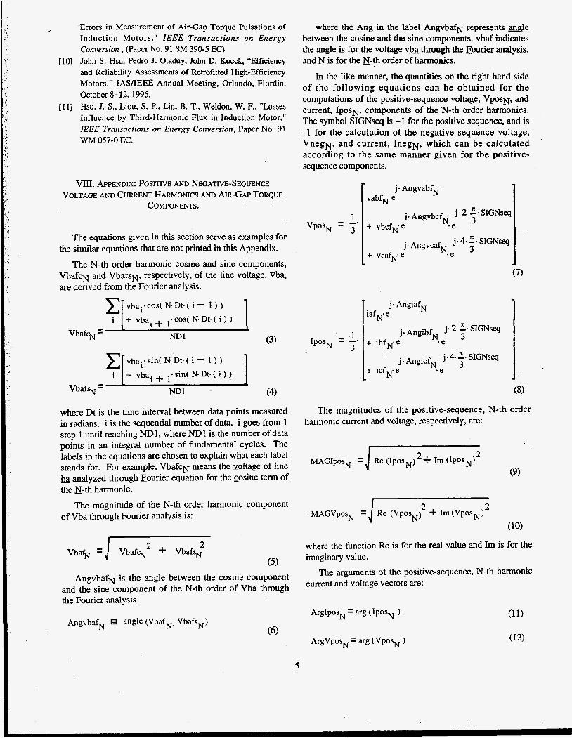
The equations given in this section serve as examples for the similar equations that are not printed in this Appendix.
The N-th order harmonic cosine and sine components, VbafcN and VbafsN, respectively, of the line voltage, vba, are derived from the Fourier analysis.
vbai.coS( N-Dt.( i - 1 ) )
(3) Vbaf% = ND 1
vbai’sin( Ne Dt. ( i - 1 ) )
VbafsN = ND1 (4)
where the Ang in the label AngvbafN represents -le between the cosine and the sine components, vbaf indicates the angle is for the voltage through the Fourier analysis, and N is for the E-th order of harmonics.
In the like manner, the quantities on the right hand side of the following equations can be obtained for the computations of the positive-sequence voltage, V~OSN, and current, IPOSN, components of the N-th order harmonics. The symbol SIGNseq is +1 for the positive sequence, and is -1 for the calculation of the negative sequence voltage, VnegN, and current, InegN, which can be calculated according to the same manner given for the positive- sequence components.
1 3 VposN = -.
’ - 1 3
IposN - --
1 j.AngvbcfN j .2- 2 + SIGNseq
+ VbCfN*e - e
+ vcafN.e . e j.AngvcafN j- 4.2. S I G N S ~
.b
(7)
j- AngiafN iafN.e
+ ibfN*e . e j. 2- SlGNsq
j. AngibfN 3
j. AngicfN j v 4. z. SIGNseq 3 + icfN- e .e
where Dt is the time interval between data points measured in radians. i is the sequential number of data. i goes from 1 step 1 until reaching ND1, where NDl is the number of data points in an integral number of fundamental cycles. The labels in the equations are chosen to explain what each label stands for. For example, V b a f c ~ means the voltage of line - ba analyzed through Fourier equation for the cosine term of the N-th harmonic.
The magnitude of the N-th order harmonic component of Vba through Fourier analysis is:
(10)
The magnitudes of the positive-sequence, N-th order harmonic current and voltage, respectively, are:
(9)
2 VbafN = / Vbafc; d- Vbafw where the function Re is for the real value and Im is for the
imaginary value. . .
The arguments of the positive-sequence, N-th harmonic AngvbafN is the angle between the cosine component and the sine component of the N-th order of Vba through current and vectors are:
the Fourier analysis
AngvbafN angle (Vbaf N, VbafSN) ArgIposN arg ( IposN )
5
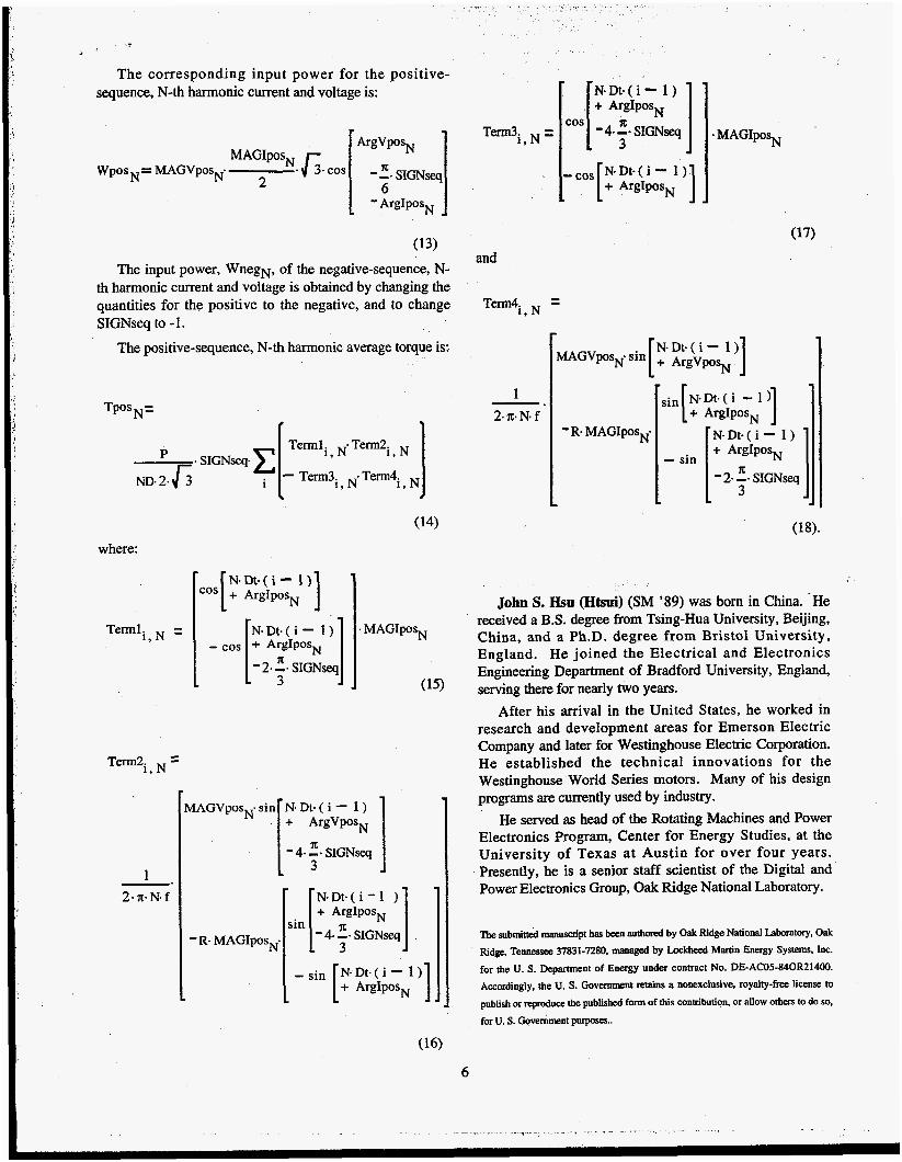
The corresponding input power for the positive- sequence, N-th harmonic current and voltage is:
ArgVposN
6
MAGI posN
2 WPOS = MAGVposN- . J;- cos - 2. SIGNseq
1 1 - ArgIposN
(13) The input power, WnegN, of the negative-sequence, N-
th harmonic current and voltage is obtained by changing the quantities for the positive to the negative, and to change SIGNseq to - 1.
The positive-sequence, N-th harmonic average torque is:
- S I G N S ~ ~ . C
ND. 2. $3 i
where:
Termli, =
T e d i , =
1 2-n-N*f
N-Dt.( i - 1) - cos + ArgIpos [ - 2. ;.
MAGVposN. sin 1 N.Dt.( i - 1 ) + ArgVposN
Tem13~, = MAGIposN
and
Tem4. = 1, N
1 2- IC* N- f -.
N- Dt- ( i - MAGVpsN' sin [ + ArgVposi '1 1 'R. MAGIposN* N.Dt-( i - 1 )
+ ArgIposN
- (18).
6
John S. J3su (Htsui) (SM '89) was born in China. -He received a B.S. degree from Tsing-Hua University, Beijing, China, and a Ph.D. degree from Bristol University, England. He joined the Electrical and Electronics Engineering Department of Bradford University, England, serving there for nearly two years.
After his arrival in the United States, he worked in research and development areas for Emerson Electric Company and later for Westinghouse Electric Corporation. He established the technical innovations for the Westinghouse World Series motors. Many of his design programs are currently used by industry.
He served as head of the Rotating Machines and Power Electronics Program, Center for Energy Studies, at the University of Texas at Austin for over four years. Presently, he is a senior staff scientist of the Digital and Power Electronics Group, Oak Ridge National Laboratory.
nK submitted manuscript has been authond by Oak Ridge National Laboratory, Oak Ridge, Tennessee 37831-7280, menaged by Lockheed Martin Energy Systems. hc. for the U. S. Department of Energy under contract No. DE-AC05-840R21400. Accordingly, the U. S. Government retains a nonexclusive, royalty-free license to publish or reproduce the published form of this contribution. or allow others to do so. for U. S. Government purposes..
- -_ . . . .. ._._ . .. ... ... - . . .- - .--- .... - . - . .. . .