Embed Size (px)
Citation preview
Corp. R&D
PURCHASE SPECIFICATION
GROUP : SAG/BHEL CORP R&D
SAG-535-48-01 REV NO: 00
PAGE : 1 OF 12
SAG/BHELR&D
COPY RIGHT AND CONFIDENTIAL The information on this document is the property of Bharat Heavy Electricals Limited.
It must not be used directly or indirectly in anyway detrimental to the interest to the company
SUPPLY OF BOS, PCU, ACDB AND E&C OF 30 kWp GRID CONNECTED FLOATING SPV
POWER PLANT
Corp. R&D
PURCHASE SPECIFICATION
GROUP : SAG/BHEL CORP R&D
SAG-535-48-01 REV NO: 00
PAGE : 2 OF 12
SAG/BHELR&D
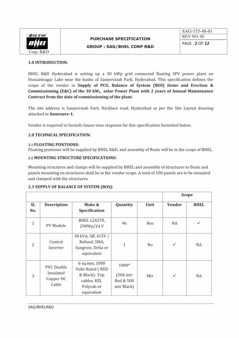
1.0 INTRODUCTION:
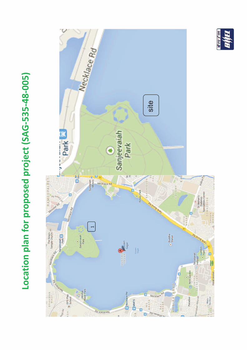
BHEL R&D Hyderabad is setting up a 30 kWp grid connected floating SPV power plant on
Hussainsagar Lake near the banks of Sanjeevaiah Park, Hyderabad. This specification defines the
scope of the vendor in Supply of PCU, Balance of System (BOS) items and Erection &
Commissioning (E&C) of the 30 kWp solar Power Plant with 2 years of Annual Maintenance
Contract from the date of commissioning of the plant.
The site address is Sanjeevaiah Park, Necklace road, Hyderabad as per the Site Layout drawing
attached in Annexure-1.
Vendor is required to furnish clause-wise response for this specification furnished below.
2.0 TECHNICAL SPECIFICATION:
2.1 FLOATING PONTOONS:
Floating pontoons will be supplied by BHEL R&D, and assembly of floats will be in the scope of BHEL.
2.2 MOUNTING STRUCTURE SPECIFICATIONS:
Mounting structures and clamps will be supplied by BHEL and assembly of structures to floats and
panels mounting on structures shall be in the vendor scope. A total of 100 panels are to be mounted
and clamped with the structures.
2.3 SUPPLY OF BALANCE OF SYSTEM (BOS):
Scope
Sl.
No.
Description Make &
Specification
Quantity Unit Vendor BHEL
1 PV Module
BHEL L24270,
290Wp/24 V 96 Nos NA ü
2 Central
Inverter
30 kVA, 3Ø, 415V /
Refusol, SMA,
Sungrow, Delta or
equivalent
1 No ü NA
3
PVC Double
Insulated
Copper DC
Cable
6 sq.mm, 1000
Volts Rated ( RED
& Black)- Top
cables, KEI,
Polycab or
equivalent
1000*
(500 mtr
Red & 500
mtr Black)
Mtr ü NA
Corp. R&D
PURCHASE SPECIFICATION
GROUP : SAG/BHEL CORP R&D
SAG-535-48-01 REV NO: 00
PAGE : 3 OF 12
SAG/BHELR&D
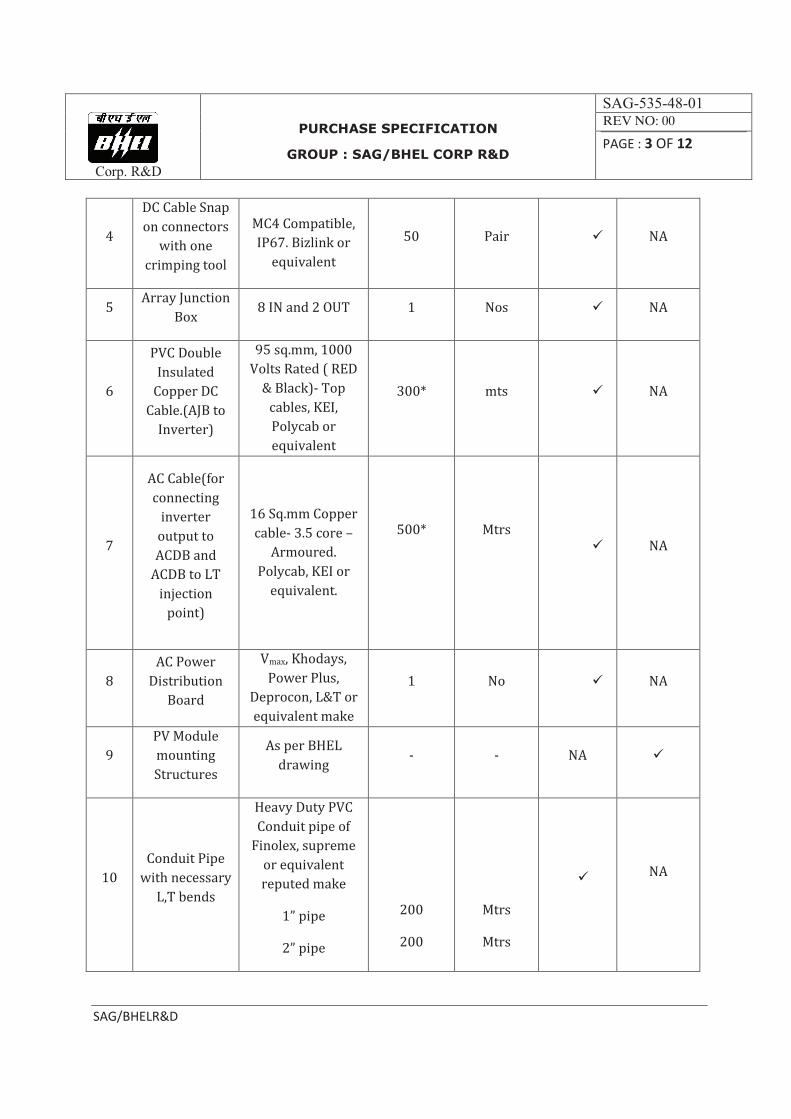
4
DC Cable Snap
on connectors
with one
crimping tool
MC4 Compatible,
IP67. Bizlink or
equivalent
50 Pair ü NA
5 Array Junction
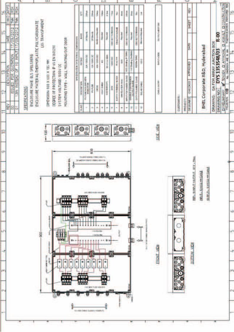
Box 8 IN and 2 OUT 1 Nos ü NA
6
PVC Double
Insulated
Copper DC
Cable.(AJB to
Inverter)
95 sq.mm, 1000
Volts Rated ( RED
& Black)- Top
cables, KEI,
Polycab or
equivalent
300* mts ü NA
7
AC Cable(for
connecting
inverter
output to
ACDB and
ACDB to LT
injection
point)
16 Sq.mm Copper
cable- 3.5 core –
Armoured.
Polycab, KEI or
equivalent.
500*
Mtrs
ü NA
8
AC Power
Distribution
Board
Vmax, Khodays,
Power Plus,
Deprocon, L&T or
equivalent make
1 No ü NA
9
PV Module
mounting
Structures
As per BHEL
drawing - - NA ü
10
Conduit Pipe
with necessary
L,T bends
Heavy Duty PVC
Conduit pipe of
Finolex, supreme
or equivalent
reputed make
1” pipe
2” pipe
200
200
Mtrs
Mtrs
ü
NA
Corp. R&D
PURCHASE SPECIFICATION
GROUP : SAG/BHEL CORP R&D
SAG-535-48-01 REV NO: 00
PAGE : 4 OF 12
SAG/BHELR&D
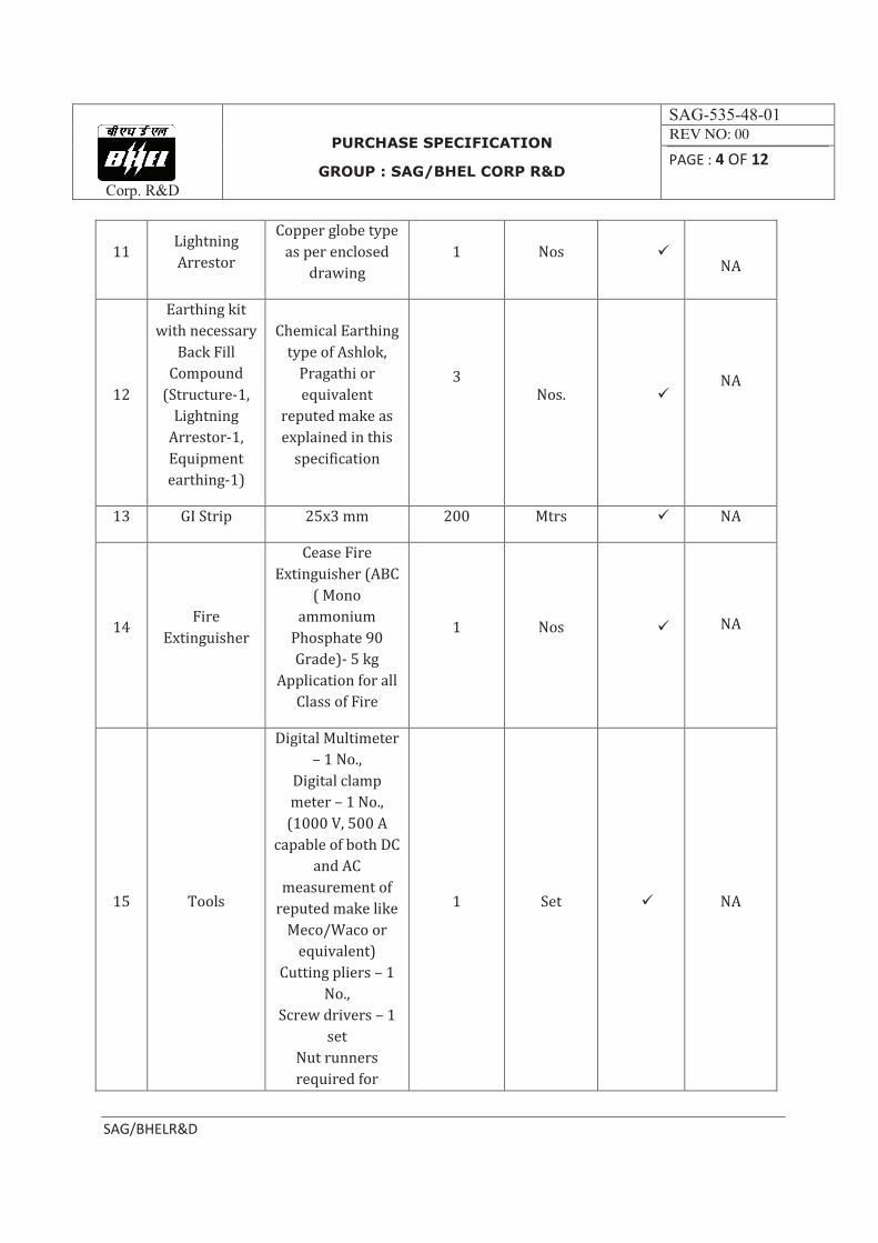
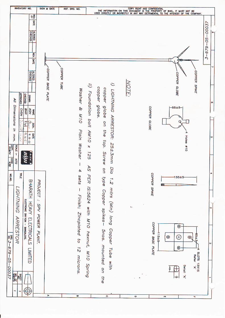
11 Lightning
Arrestor
Copper globe type
as per enclosed
drawing
1 Nos ü
NA
12
Earthing kit
with necessary
Back Fill
Compound
(Structure-1,
Lightning
Arrestor-1,
Equipment
earthing-1)
Chemical Earthing
type of Ashlok,
Pragathi or
equivalent
reputed make as
explained in this
specification
3
Nos. ü
NA
13 GI Strip 25x3 mm 200 Mtrs ü NA
14 Fire
Extinguisher
Cease Fire
Extinguisher (ABC
( Mono
ammonium
Phosphate 90
Grade)- 5 kg
Application for all
Class of Fire
1 Nos ü
NA
15 Tools
Digital Multimeter
– 1 No.,
Digital clamp
meter – 1 No.,
(1000 V, 500 A
capable of both DC
and AC
measurement of
reputed make like
Meco/Waco or
equivalent)
Cutting pliers – 1
No.,
Screw drivers – 1
set
Nut runners
required for
1 Set ü NA
Corp. R&D
PURCHASE SPECIFICATION
GROUP : SAG/BHEL CORP R&D
SAG-535-48-01 REV NO: 00
PAGE : 5 OF 12
SAG/BHELR&D
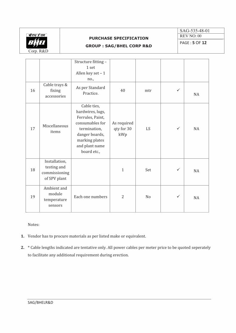
Structure fitting –
1 set
Allen key set – 1
no.,
16
Cable trays &
fixing
accessories
As per Standard
Practice. 40 mtr ü
NA
17 Miscellaneous
items
Cable ties,
hardwires, lugs,
Ferrules, Paint,
consumables for
termination,
danger boards,
marking plates
and plant name
board etc.,
As required
qty for 30
kWp
LS ü NA
18
Installation,
testing and
commissioning
of SPV plant
1 Set ü
NA
19
Ambient and
module
temperature
sensors
Each one numbers 2 No ü
NA
Notes:
1. Vendor has to procure materials as per listed make or equivalent.
2. * Cable lengths indicated are tentative only. All power cables per meter price to be quoted seperately
to facilitate any additional requirement during erection.
Corp. R&D
PURCHASE SPECIFICATION
GROUP : SAG/BHEL CORP R&D
SAG-535-48-01 REV NO: 00
PAGE : 6 OF 12
SAG/BHELR&D
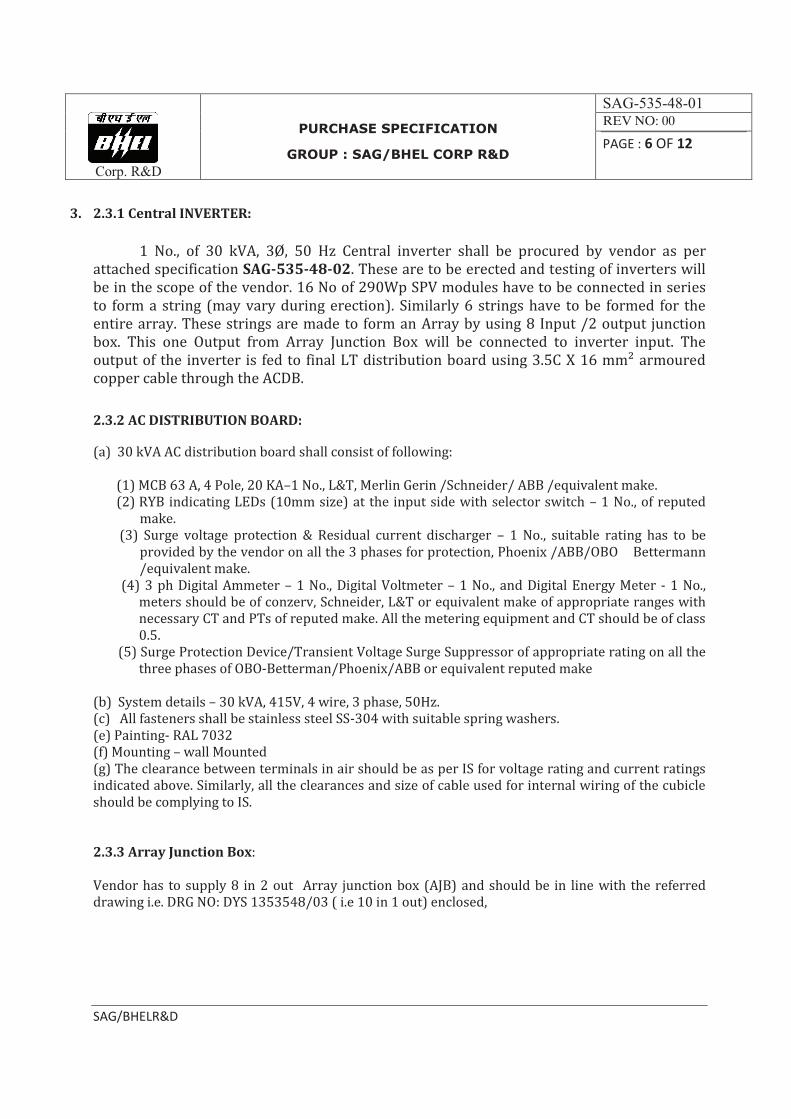
3. 2.3.1 Central INVERTER:
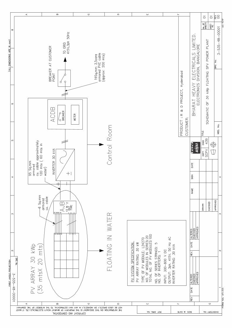
1 No., of 30 kVA, 3Ø, 50 Hz Central inverter shall be procured by vendor as per attached specification SAG-535-48-02. These are to be erected and testing of inverters will be in the scope of the vendor. 16 No of 290Wp SPV modules have to be connected in series to form a string (may vary during erection). Similarly 6 strings have to be formed for the entire array. These strings are made to form an Array by using 8 Input /2 output junction box. This one Output from Array Junction Box will be connected to inverter input. The output of the inverter is fed to final LT distribution board using 3.5C X 16 mm² armoured copper cable through the ACDB.
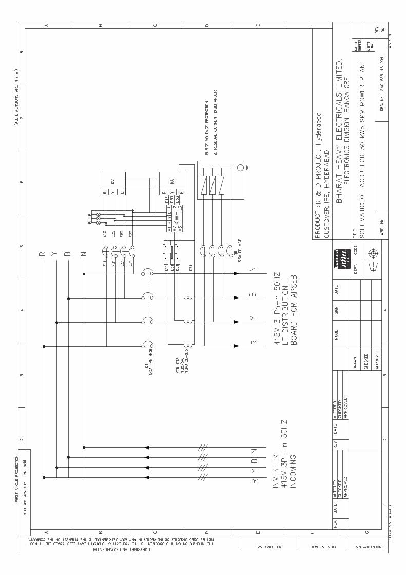
2.3.2 AC DISTRIBUTION BOARD:
(a) 30 kVA AC distribution board shall consist of following: (1) MCB 63 A, 4 Pole, 20 KA–1 No., L&T, Merlin Gerin /Schneider/ ABB /equivalent make.
(2) RYB indicating LEDs (10mm size) at the input side with selector switch – 1 No., of reputed make.
(3) Surge voltage protection & Residual current discharger – 1 No., suitable rating has to be provided by the vendor on all the 3 phases for protection, Phoenix /ABB/OBO Bettermann /equivalent make.
(4) 3 ph Digital Ammeter – 1 No., Digital Voltmeter – 1 No., and Digital Energy Meter - 1 No., meters should be of conzerv, Schneider, L&T or equivalent make of appropriate ranges with necessary CT and PTs of reputed make. All the metering equipment and CT should be of class 0.5.
(5) Surge Protection Device/Transient Voltage Surge Suppressor of appropriate rating on all the three phases of OBO-Betterman/Phoenix/ABB or equivalent reputed make
(b) System details – 30 kVA, 415V, 4 wire, 3 phase, 50Hz. (c) All fasteners shall be stainless steel SS-304 with suitable spring washers. (e) Painting- RAL 7032 (f) Mounting – wall Mounted (g) The clearance between terminals in air should be as per IS for voltage rating and current ratings indicated above. Similarly, all the clearances and size of cable used for internal wiring of the cubicle should be complying to IS. 2.3.3 Array Junction Box: Vendor has to supply 8 in 2 out Array junction box (AJB) and should be in line with the referred drawing i.e. DRG NO: DYS 1353548/03 ( i.e 10 in 1 out) enclosed,
Corp. R&D
PURCHASE SPECIFICATION
GROUP : SAG/BHEL CORP R&D
SAG-535-48-01 REV NO: 00
PAGE : 7 OF 12
SAG/BHELR&D
2.3.4 Power & Control Cables:
- Power Cables of adequate rating shall be required for interconnection of:
- Modules/panels within array
-PV array & Junction Box
-Junction Box & Inverter
-Inverter & ACDB
-ACDB & LT Panel.
ii. The power cable shall be 1.1kv grade, heavy duty, stranded copper/ aluminum conductor, PVC type A insulated, galvanized steel wire/strip armoured, flame retardant low smoke (FRLS) extruded PVC type ST-1 outer sheathed. The cables shall, in general conform to IS-1554 Part-I & other relevant standards.
iii. Control Cables: The cable shall be 1.1kv grades, heavy duty, stranded copper conductor, PVC type A insulated, galvanized steel wire/strip armoured, flame retardant low smoke (FRLS) extruded PVC type ST-1 outer sheathed. The cables shall, in general conform to IS-1554 Part-I & other relevant standards.
iv. The permissible voltage drop from the SPV Generator to the Charge controller shall not be more than 2% of peak power voltage of the SPV power source (generating system). In the light of this fact the cross-sectional area of the cable chosen is such that the voltage drop introduced by it shall be within 2% of the system voltage at peak power.
v. All connections should be properly terminated, soldered and/or sealed from outdoor and indoor elements. Relevant codes and operating manuals must be followed. Extensive wiring and terminations (connection points) for all PV components is needed along with electrical connection to lighting loads.
2.3.5 Communication Interface and SCADA:
a). The project envisages a communication interface which shall be able to support.
o Real time data logging o Event logging o Supervisory control o Operational modes o Set point editing
Corp. R&D
PURCHASE SPECIFICATION
GROUP : SAG/BHEL CORP R&D
SAG-535-48-01 REV NO: 00
PAGE : 8 OF 12
SAG/BHELR&D
o Software and communication compatibility: a) Optical port with RS 485/ ETHERNET compatible to transfer the data locally through CMRI & remote through Optical fiber link to the main computer.
b) The Supplier shall supply necessary Software required. The supplier shall also provide training for the use of software. The software should be compatible to Microsoft windows systems (Windows VISTA OR Higher Version system).
c) Copy of operation manual shall be supplied.
d) The Supplier shall provide meter reading protocols.
ii. The following parameters shall also be measured and displayed continuously.
a. Solar system (module) temperature.
b. Ambient temperature.
c. Should have provision for solar irradiation/isolation
d. DC current and Voltages
e. DC injection into the grid (one time measurement at the time of installation).
f. Efficiency of the inverter.
g. Solar system efficiency
h. Display of I-V curve of the solar system
i. Any other parameter considered necessary by supplier of the solar PV system based on rudent practice.
j. kW reading DC/AC i.e. input output (instantaneous power)
iii. Data logger/PC based monitoring system must record these parameters for study of effect of various environmental & grid parameters on energy generated by the solar system and various analyses would be required to be provided through bar charts, curves, tables.
iv. The communication interface shall be an integral part of inverter and shall be suitable to be connected to local computer and also remotely via the Web using either a standard modem or a GSM / WIFI modem.
Corp. R&D
PURCHASE SPECIFICATION
GROUP : SAG/BHEL CORP R&D
SAG-535-48-01 REV NO: 00
PAGE : 9 OF 12
SAG/BHELR&D
2.3.6 Fire Extinguishers:
An in indoor space of approximate area 16 sq mtr will be provided for the installation of PCU and associated items. This control room shall be provided with Portable fire extinguisher for fire caused by electrical short circuits. Apart from this Sand buckets shall be placed in relevant areas mandated by BIS. The installation of Fire Extinguishers should confirm to TAC regulations and BIS standards.The fire extinguishers shall be provided in the control room housing the PCUs as well as onthe roof top where the PV arrays have been installed.
2.3.7 Tools, Shackles
After completion of installation & Commissioning of the plant, necessary tools & shackles are to be provided free of cost by the supplier for the maintenance purpose.
2.3.8 Earthing Kit:
GOVERNING STANDARD: IS 3043 - 1987 The earthing for array, plant equipment and LT power system shall be required as per provisions of IS: 3043. The requirement of earthing system for the Plant shall be as furnished in the above table.
Installation of Chemical earth stations:
The Zinc electrode used for this will be of 3 m length & 80 mm diameter. So nearly 3.5 m depth & 0.5 Mtr dia hole to be drilled, 2 bags of 25 kgs of back fill compound to be filled along with electrode & water into the pit. Hence vendor has to organize the required machines & tools for earthing. .
The structures shall be inter-connected through interconnects and finally connected through 25 mm x 3 mm thick GI flat to the respective earth pits from roof top. This GI strip is to be properly routed from terrace to corresponding earthing pit through PVC pipe with bends properly by clamping to wall at regular intervals. Vendor has to make necessary arrangements to ensure proper routing and maintain the aesthetic look of the platform. Please note that GI flat to be painted by Asian paint 3 Mango type before lying.
GI flat is to be used for earthing the body of the LTDB & PCU to the earth pits. The GI flat has to be run all along the length of the cable trench through PVC conduits with bends till earthing points. The GI flat from equipment body earth is connected to this flat and is connected to the dedicated earthing pit. Masonry enclosure (identified with labels) with cast iron cover plate shall be provided for each earth pit.
Earth resistance of the earth pits shall be tested in presence of the representative of BHEL as per applicable IS before commissioning and value to be less than 3Ω for structures and to be less than 1Ω
for equipment body earthing for acceptance.
Corp. R&D
PURCHASE SPECIFICATION
GROUP : SAG/BHEL CORP R&D
SAG-535-48-01 REV NO: 00
PAGE : 10 OF 12
SAG/BHELR&D
2.3.9 Danger Boards, Marking & plant name board:
(1). Danger plates (200mmx150mm) shall be provided in solar array area. Suitable size of each Danger Notice plates shall be provided as per statutory requirement, made of mild steel of min 2 mm thick, and vitreous enameled RED on both sides and with inscription in signal WHITE color on front side as required. The inscriptions shall be in English and local language. (2) Marking plates/Sticker are to be made and should be attached to LAs, earthing pits, along the cable routing up to LT panel room for easier identification. The detailed size and matter to be inscribed will be given after installation.
(3) The name board of approx., 3 m x 1 m will contain brief description of the Power plant. The board
will be made of steel plate/Acrylic sheet. Letters on the board have to be with proper illumination
arrangement. The design and size of the sign board shall have to be befitting with Control Room and
should be submitted for prior approval of BHEL before ordering.
NOTE: The drawing WITH DIMENSIONS of the name boards & marking plates are to be submitted for prior approval to BHEL before procuring.
2.4 Erection & Commissioning of 30 kWp Floating system:
A) The shifting of all the materials to the assembly and erection point/control room from storage
location (BHEL R&D, Vikas Nagar) for erection will be in the scope of the vendor and he has to make
necessary arrangements for the same. The storage, watch & ward responsibility of all the materials
including BHEL supplies at site will be in vendor’s scope until the commissioning of the plant. Any
deficit occurring due to misplacement/mishandling will be borne by the vendor at no extra cost.
B) 96 Nos of 290 Wp SPV modules have to be assembled using structure materials as per drawing (will be provided in the due course). The PV modules are to be carefully mounted on this structure with the necessary clamps and fixtures. Earthing strip has to be run neatly through the PVC pipes and bends, should be connected to the earthing pits installed. Any activities requiring holes drilling, cutting for completing the installation and mounting of PV
modules on the structures and other works is in the vendor’s scope. Vendor has to make necessary
arrangement for the drilling machine/gas cutting machine, if required.
C) Before mounting the PV modules on to the structures, each PV module has to be tested during peak sunshine period. Short circuit current (Isc) & Open circuit voltage (Voc) of the module has to be checked & recorded using multimeter and Clamp meter. Ensure the modules are electrically OK and then only mount them on structures. D) 16 numbers of PV modules of each 290 Wp are to be connected in series using quick connects with cables supplied along with PV modules. +ve & -ve terminals of each string has to be routed to Array Junction Box. Vendor shall supply the MC4 type male / female connectors and the suitable crimping tool required for making interconnection. On either side and throughout the routing of the cables through pipes marking has to be done. The number of PV modules connected in series
Corp. R&D
PURCHASE SPECIFICATION
GROUP : SAG/BHEL CORP R&D
SAG-535-48-01 REV NO: 00
PAGE : 11 OF 12
SAG/BHELR&D
indicated above is tentative; this may vary depending on the make of PCU. This will be decided before commencement of work. Special crimping tools required for crimping to be arranged by Vendor as per this specification, have to be used to crimp 4 sq mm cables to quick connects for connecting output of series strings to inverter inputs. These crimping tools has to be kept at site permanently even after completion of project for O&M purpose.
E) Each string Open circuit Voltage & Short Circuit Current to be checked and recorded at site. F) The terminations at PCU, ACDB and customer LT panel will be in the scope of the vendor. The necessary Copper lugs of appropriate dimensions and hardware required for the termination have to be arranged by the vendor. Vendor has to ensure that terminations have been made without any over-tension and stress on the cable connected.
Note: Vendor have to carefully measure the exact length of 4 mm2 required for the connections between strings and PCU before cutting the cable from cable drum. Any short fall in length of cable arising out of vendor works should be borne by the vendor.
For 4 mm2 cable termination, appropriate marking with Ferrules and corresponding string numbers have to be done by the vendor. The necessary Ferrules have to be arranged by the vendor.
The DC cables from the array have to be terminated on the PCU with proper labeling.
G) The 3 phase output from the PCU is connected to ACDB by means of 3.5 C 16 sq.mm cable. All these cables have to be run through appropriate PVC pipes routed to ensure aesthetic look. Appropriate cable lugs and crimping tools for terminations have to be arranged by vendor.
H) The output cable from ACDB has to be routed to LT panel feeder terminals in the power house on the first platform by means of 1 run of 3.5C 16 mm2 copper cables and routed through PVC conduits. Termination up to LT panel is under vendor’s scope. Appropriate sized lugs should be supplied by the vendor and termination by proper crimping will be in the scope of vendor. Necessary crimping tools/tackles to be arranged by vendor at site.
I) Installation of the Lightning arrestor and 3 nos., of earthing pits will be in the scope of vendor. The necessary arrangements of digging and running the earthing strip from module array in water to the bank will be in the scope of vendor. Vendor has to neatly route the GI strip through PVC conduits, clamp the Pipe at regular intervals and should ensure aesthetic look of the platform. GI strip is to be painted with two coats of Aluminium paint of Asian 3 Mango type before installation.
J) Vendor shall associate with the other vendor’s (Floats and mooring, mounting structures, and control room) technical team during erection & pre-commissioning checks and in commissioning of the power plant.
K) The vendor has to receive BHEL/BHEL vendor’s material at the site. The vendor has to make
necessary arrangement to store the material and arrange for watch & ward very near to the site. The safe custody of all the materials until the completion of project and handing over will be in the scope of vendor.
Corp. R&D
PURCHASE SPECIFICATION
GROUP : SAG/BHEL CORP R&D
SAG-535-48-01 REV NO: 00
PAGE : 12 OF 12
SAG/BHELR&D
L) The left out quantity of material procured for the execution of this project shall be handed over to BHEL after completing the commissioning.
M) The contractor shall take all the necessary measures to prevent accidents. It is the responsibility of the contractor not to allow any worker to work in an unsafe condition, nor with unsafe equipment.
N) The contractor shall provide adequate and suitable Personal Protective Equipments (PPEs), wherever they are required, to all concerned personnel. The quality of this equipment’s shall conform to National (BIS) or International Standards.
2.5 Warranty:
· Vendor has to provide the on-site warranty (labour, parts) for a period of minimum 2 years
from the date of successful commissioning (for vendor’s scope of supply & work).
· Vendor shall attend the fault within 48 hours from the reporting time. Vendor shall furnish
the fault report by giving details of fault, action taken and steps to prevent occurrence.
· Vendor has to supply necessary spares including consumables for continuous operation of
plant for the warranty period for the successful commissioning.
2.6 Test Certificates:
· Warranty certificates shall be submitted for all bought-out items along with the shipment.
2.7 List of enclosures:
1. SLD of 30 kWp SPV plant. DRG No:3-535-48-00001
2. Floating pontoon drawing with structures drawing and PV array layout drawing (will be provided at the time of commencement of erection of the plant).
3. SPV Module Spec. No:CD-4-4001-106, R-01
4. Schematic of Lightning Arrestor. DRG No:3-679-05-00037
5. Reference Array junction box drawing: DYS 1353548/03 (i.e. 10 IN 1 Out)- for reference only
6. ACDB drawing No: DRG No: SAG-535-48-004
7. Compilation sheet: No: SAG-535-48-003
8. Site location drawing: SAG-535-48-005
---00---
Cor. R&D
PURCHASE SPECIFICATION
GROUP :SAG/48
PS-535-48-02
REV NO: 00
PAGE : 1 OF 8
SAG/48
TECHNICAL SPECIFICATIONS FOR SUPPLY, ERECTION & COMMISSIONING OF
GRID CONNECTED 30KW POWER CONDITIONING UNIT AT HUSSAIN SAGAR
HYDERABAD.
COPY RIGHT AND CONFIDENTIAL The information on this document is the property of Bharat Heavy Electricals Limited.
It must not be used directly or indirectly in anyway detrimental to the interest to the
Cor. R&D
PURCHASE SPECIFICATION
GROUP :SAG/48
PS-535-48-02
REV NO: 00
PAGE : 2 OF 8
SAG/48
1. INTRODUCTION:
BHEL Corp. R&D is setting up a 30kWp Grid Connected SPV Power Plant at HUSSAIN SAGAR
HYDERABAD near Sanjeevaiah Park. This technical specification provides details of supply of
Power Conditioning Unit (PCU), installation, system integration, pre-commissioning checks,
commissioning of the PCU along with data logger software, Comprehensive Annual Maintenance
Contract of the PCU for a period of two years from the date of commissioning. The scope also
includes providing PCU along with cabinet temperature and PV module surface temperature
sensor with adequate length cables.
2.0 ELIGIBILITY CRITERIA:
(a). Supply of Grid connected 30 KW central PCU.
(b).Vendor should have successfully supplied, installed and commissioned within the past one
year min. 30 kW and above rated Grid Connect PCUs for SPV Power Plant. Copy of Certificate of
completion issued by the end customer shall be furnished.
(c). Vendor should confirm that he has an established service center along with required spares
and manpower within India for maintenance of grid connected power conditioning units of rating
30 kVA and above.Details of such service centers shall be furnished.
(d). If vendor has business tie-up with a foreign manufacturer, a copy of the business agreement
shall be attached with the offer. Such business agreement shall be;
(i). in force on date,
(ii). Authorization from principal manufacturer to the vendor that;
(1). He is authorized to quote for Indian Territory
(2). He is authorized to erect, commission and service.
(3). Confirmation from the principal vendor, that vendor representatives have been
trained in for Erection & commissioning and repairs.
All the above conditions must be met in order to qualify.
(3). SCOPE OF SUPPLY, I & C, AND WARRANTY FOR 2 YEARS
This specification covers the design, manufacture, supply, installation, testing and commissioning
of 30kVA PCU at Sanjeevaiah Park Hyderabad. The vendor has to attend to any complaint/break
down within 48 hours from the date of complaint. Any component replaced and labour involved
during the 2 years on-site warranty period shall be free of cost. Warranty period shall start from
date of successful commissioning.
Cor. R&D
PURCHASE SPECIFICATION
GROUP :SAG/48
PS-535-48-02
REV NO: 00
PAGE : 3 OF 8
SAG/48
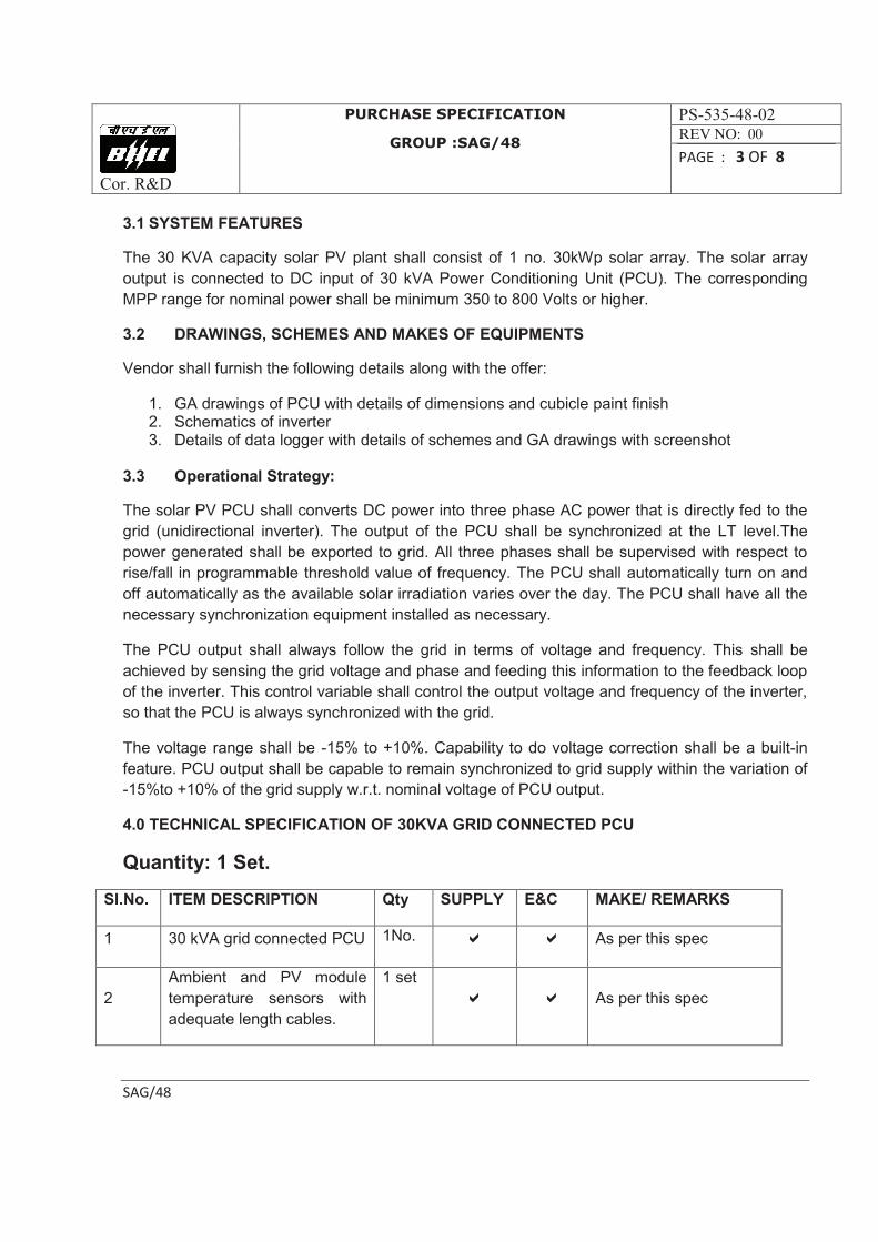
3.1 SYSTEM FEATURES
The 30 KVA capacity solar PV plant shall consist of 1 no. 30kWp solar array. The solar array
output is connected to DC input of 30 kVA Power Conditioning Unit (PCU). The corresponding
MPP range for nominal power shall be minimum 350 to 800 Volts or higher.
3.2 DRAWINGS, SCHEMES AND MAKES OF EQUIPMENTS
Vendor shall furnish the following details along with the offer:
1. GA drawings of PCU with details of dimensions and cubicle paint finish 2. Schematics of inverter 3. Details of data logger with details of schemes and GA drawings with screenshot
3.3 Operational Strategy:
The solar PV PCU shall converts DC power into three phase AC power that is directly fed to the
grid (unidirectional inverter). The output of the PCU shall be synchronized at the LT level.The
power generated shall be exported to grid. All three phases shall be supervised with respect to
rise/fall in programmable threshold value of frequency. The PCU shall automatically turn on and
off automatically as the available solar irradiation varies over the day. The PCU shall have all the
necessary synchronization equipment installed as necessary.
The PCU output shall always follow the grid in terms of voltage and frequency. This shall be
achieved by sensing the grid voltage and phase and feeding this information to the feedback loop
of the inverter. This control variable shall control the output voltage and frequency of the inverter,
so that the PCU is always synchronized with the grid.
The voltage range shall be -15% to +10%. Capability to do voltage correction shall be a built-in
feature. PCU output shall be capable to remain synchronized to grid supply within the variation of
-15%to +10% of the grid supply w.r.t. nominal voltage of PCU output.
4.0 TECHNICAL SPECIFICATION OF 30KVA GRID CONNECTED PCU
Quantity: 1 Set.
Sl.No. ITEM DESCRIPTION Qty SUPPLY E&C MAKE/ REMARKS
1 30 kVA grid connected PCU 1No. a a As per this spec
2
Ambient and PV module
temperature sensors with
adequate length cables.
1 set
a a As per this spec
Cor. R&D
PURCHASE SPECIFICATION
GROUP :SAG/48
PS-535-48-02
REV NO: 00
PAGE : 4 OF 8
SAG/48
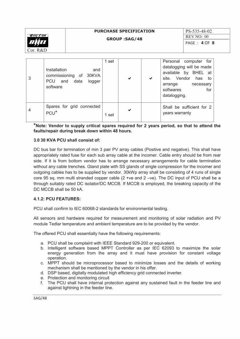
3
Installation and
commissioning of 30KVA
PCU and data logger
software
1 set
a a
Personal computer for
datalogging will be made
available by BHEL at
site. Vendor has to
arrange necessary
softwares for
datalogging.
4 Spares for grid connected
PCU*
1 set a
Shall be sufficient for 2
years warranty
*Note: Vendor to supply critical spares required for 2 years period, so that to attend the
faults/repair during break down within 48 hours.
3.0 30 KVA PCU shall consist of:
DC bus bar for termination of min 3 pair PV array cables (Positive and negative). This shall have
appropriately rated fuse for each sub array cable at the incomer. Cable entry should be from rear
side. If it is from bottom vendor has to arrange necessary arrangements for cable termination
without any cable trenches. Gland plate with SS glands of single compression for the incomer and
outgoing cables has to be supplied by vendor. 30kWp array shall be consisting of 4 runs of single
core 95 sq. mm multi stranded copper cable (2 +ve and 2 –ve). The DC input of PCU shall be a
through suitably rated DC isolator/DC MCCB. If MCCB is employed, the breaking capacity of the
DC MCCB shall be 50 kA.
4.1.2: PCU FEATURES:
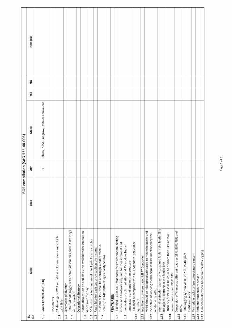
PCU shall confirm to IEC 60068-2 standards for environmental testing.
All sensors and hardware required for measurement and monitoring of solar radiation and PV
module Tedlar temperature and ambient temperature are to be provided by the vendor.
The offered PCU shall essentially have the following requirements:
a. PCU shall be complaint with IEEE Standard 929-200 or equivalent. b. Intelligent software based MPPT Controller as per IEC 62093 to maximize the solar
energy generation from the array and it must have provision for constant voltage operation.
c. MPPT should be microprocessor based to minimize losses and the details of working mechanism shall be mentioned by the vendor in his offer.
d. DSP based, digitally modulated high efficiency grid connected inverter. e. Protection and monitoring circuit f. The PCU shall have internal protection against any sustained fault in the feeder line and
against lightning in the feeder line.
Cor. R&D
PURCHASE SPECIFICATION
GROUP :SAG/48
PS-535-48-02
REV NO: 00
PAGE : 5 OF 8
SAG/48
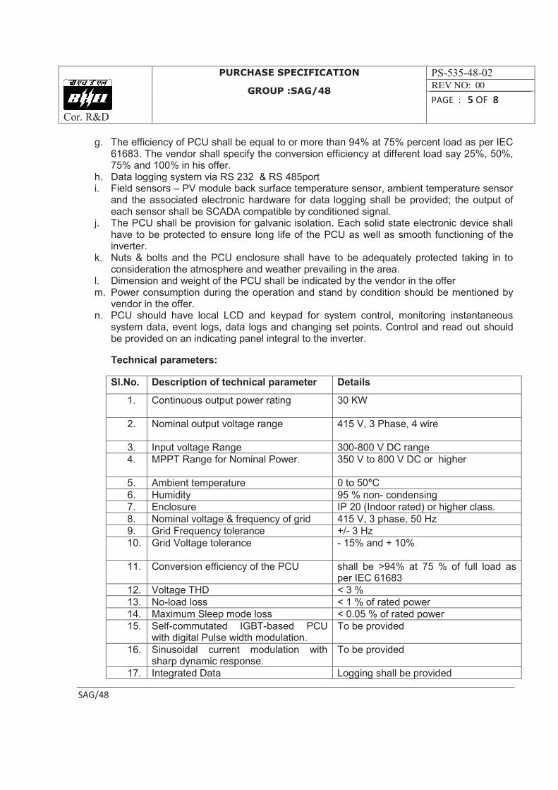
g. The efficiency of PCU shall be equal to or more than 94% at 75% percent load as per IEC 61683. The vendor shall specify the conversion efficiency at different load say 25%, 50%, 75% and 100% in his offer.
h. Data logging system via RS 232 & RS 485port i. Field sensors – PV module back surface temperature sensor, ambient temperature sensor
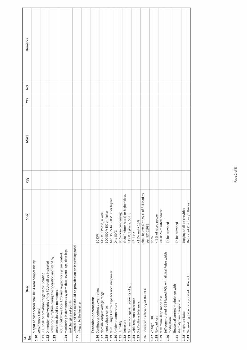
and the associated electronic hardware for data logging shall be provided; the output of each sensor shall be SCADA compatible by conditioned signal.
j. The PCU shall be provision for galvanic isolation. Each solid state electronic device shall have to be protected to ensure long life of the PCU as well as smooth functioning of the inverter.
k. Nuts & bolts and the PCU enclosure shall have to be adequately protected taking in to consideration the atmosphere and weather prevailing in the area.
l. Dimension and weight of the PCU shall be indicated by the vendor in the offer m. Power consumption during the operation and stand by condition should be mentioned by
vendor in the offer. n. PCU should have local LCD and keypad for system control, monitoring instantaneous
system data, event logs, data logs and changing set points. Control and read out should be provided on an indicating panel integral to the inverter.
Technical parameters:
Sl.No. Description of technical parameter Details
1. Continuous output power rating
30 KW
2. Nominal output voltage range 415 V, 3 Phase, 4 wire
3. Input voltage Range 300-800 V DC range
4. MPPT Range for Nominal Power.
350 V to 800 V DC or higher
5. Ambient temperature 0 to 50°C
6. Humidity 95 % non- condensing
7. Enclosure IP 20 (Indoor rated) or higher class.
8. Nominal voltage & frequency of grid 415 V, 3 phase, 50 Hz
9. Grid Frequency tolerance +/- 3 Hz
10. Grid Voltage tolerance
- 15% and + 10%
11. Conversion efficiency of the PCU shall be >94% at 75 % of full load as per IEC 61683
12. Voltage THD < 3 %
13. No-load loss < 1 % of rated power
14. Maximum Sleep mode loss < 0.05 % of rated power
15. Self-commutated IGBT-based PCU with digital Pulse width modulation.
To be provided
16. Sinusoidal current modulation with sharp dynamic response.
To be provided
17. Integrated Data Logging shall be provided
Cor. R&D
PURCHASE SPECIFICATION
GROUP :SAG/48
PS-535-48-02
REV NO: 00
PAGE : 6 OF 8
SAG/48
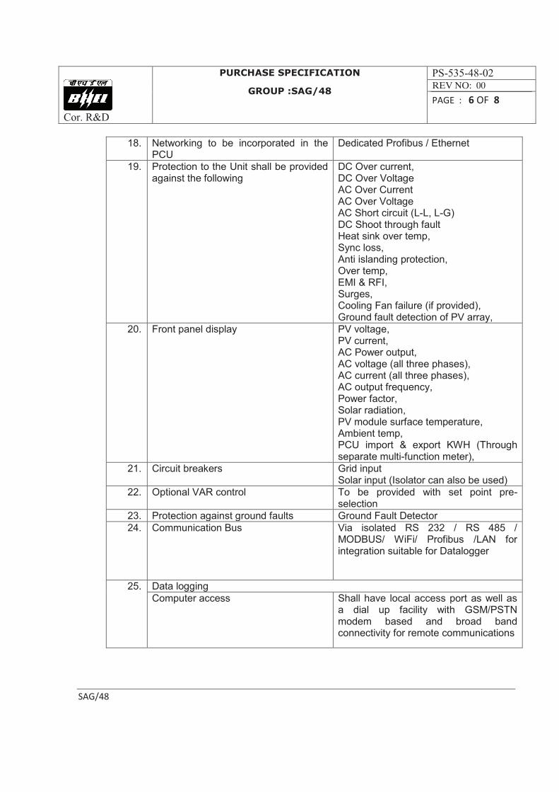
18. Networking to be incorporated in the PCU
Dedicated Profibus / Ethernet
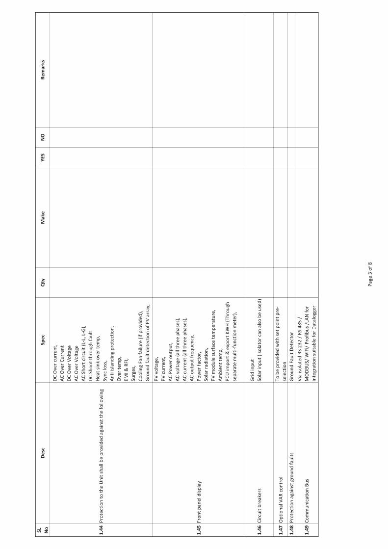
19. Protection to the Unit shall be provided against the following
DC Over current, DC Over Voltage AC Over Current AC Over Voltage AC Short circuit (L-L, L-G) DC Shoot through fault Heat sink over temp, Sync loss, Anti islanding protection, Over temp, EMI & RFI, Surges, Cooling Fan failure (if provided), Ground fault detection of PV array,
20. Front panel display PV voltage, PV current, AC Power output, AC voltage (all three phases), AC current (all three phases), AC output frequency, Power factor, Solar radiation, PV module surface temperature, Ambient temp, PCU import & export KWH (Through separate multi-function meter),
21. Circuit breakers Grid input Solar input (Isolator can also be used)
22. Optional VAR control To be provided with set point pre-selection
23. Protection against ground faults Ground Fault Detector
24. Communication Bus Via isolated RS 232 / RS 485 / MODBUS/ WiFi/ Profibus /LAN for integration suitable for Datalogger
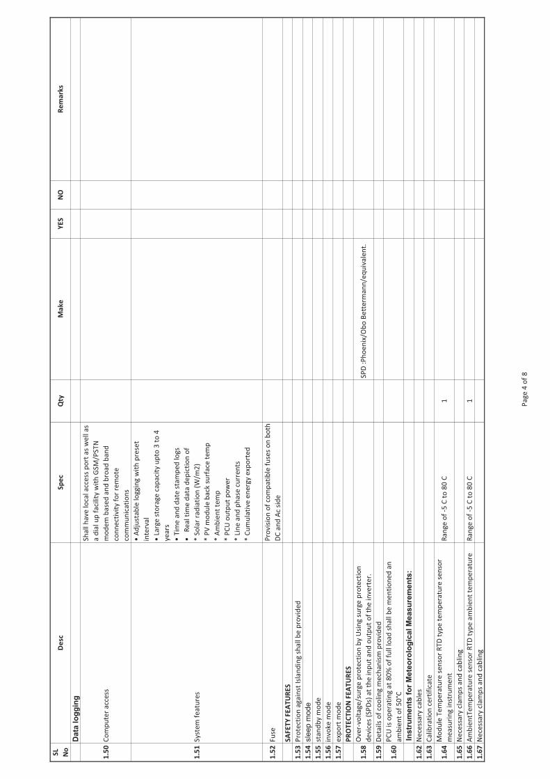
25. Data logging
Computer access Shall have local access port as well as a dial up facility with GSM/PSTN modem based and broad band connectivity for remote communications
Cor. R&D
PURCHASE SPECIFICATION
GROUP :SAG/48
PS-535-48-02
REV NO: 00
PAGE : 7 OF 8
SAG/48
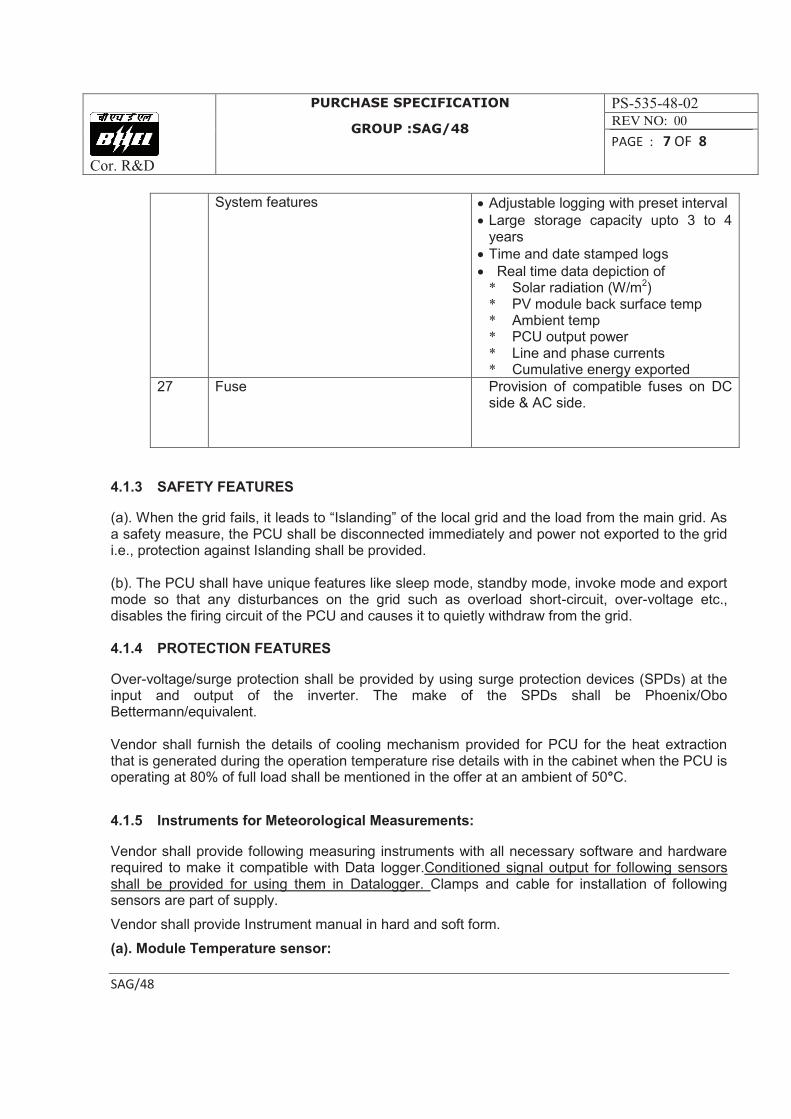
System features · Adjustable logging with preset interval
· Large storage capacity upto 3 to 4 years
· Time and date stamped logs
· Real time data depiction of * Solar radiation (W/m2) * PV module back surface temp * Ambient temp * PCU output power * Line and phase currents * Cumulative energy exported
27 Fuse Provision of compatible fuses on DC side & AC side.
4.1.3 SAFETY FEATURES
(a). When the grid fails, it leads to “Islanding” of the local grid and the load from the main grid. As a safety measure, the PCU shall be disconnected immediately and power not exported to the grid i.e., protection against Islanding shall be provided. (b). The PCU shall have unique features like sleep mode, standby mode, invoke mode and export mode so that any disturbances on the grid such as overload short-circuit, over-voltage etc., disables the firing circuit of the PCU and causes it to quietly withdraw from the grid. 4.1.4 PROTECTION FEATURES
Over-voltage/surge protection shall be provided by using surge protection devices (SPDs) at the input and output of the inverter. The make of the SPDs shall be Phoenix/Obo Bettermann/equivalent. Vendor shall furnish the details of cooling mechanism provided for PCU for the heat extraction that is generated during the operation temperature rise details with in the cabinet when the PCU is operating at 80% of full load shall be mentioned in the offer at an ambient of 50°C.
4.1.5 Instruments for Meteorological Measurements:
Vendor shall provide following measuring instruments with all necessary software and hardware required to make it compatible with Data logger.Conditioned signal output for following sensors shall be provided for using them in Datalogger. Clamps and cable for installation of following sensors are part of supply.
Vendor shall provide Instrument manual in hard and soft form.
(a). Module Temperature sensor:
Cor. R&D
PURCHASE SPECIFICATION
GROUP :SAG/48
PS-535-48-02
REV NO: 00
PAGE : 8 OF 8
SAG/48
Vendor shall also provide one RTD type temperature sensor measuring instrument at suitable place in PV array. Instrument shall have a range of -5o C to 80o C. Necessary clamps and cabling are part of supply.
(b). AmbientTemperature sensor:
Vendor shall also provide one RTD type ambient temperature measuring instrument at suitable place in PV array. Instrument shall have a range of -5o C to 80o C. Necessary clamps and cabling are part of supply.
5.0 TESTING AND INSPECTION:
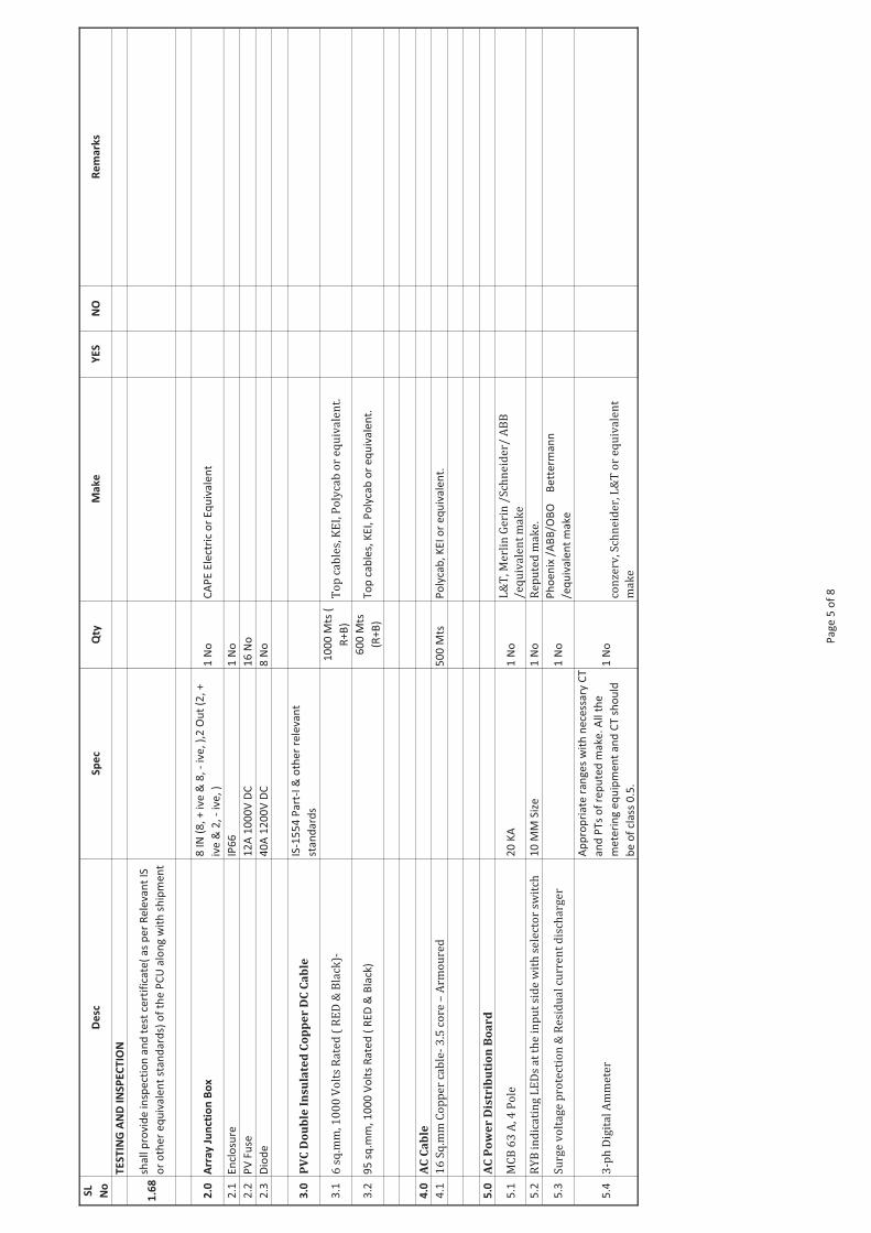
Vendor shall provide inspection and test certificate of the PCU along with shipment. Relevant IS or other equivalent standards shall be employed as the guideline for testing.
6.0 BREAKDOWN MAINTENANCE DURING WARRANTY PERIOD:
Vendor shall attend the fault within 48 hours from the reporting time. Vendor shall furnish the fault report by giving details of fault, action taken and steps to prevent occurrence.
---00---
SL
No
De
scS
pe
cQ
tyM
ak
eY
ES
NO
Re
ma
rks
1.0
Po
we
r C
on
tro
l U
nit
(PC
U)
1R
efu
sol,
SM
A,
Su
ng
row
, D
elt
a o
r e
qu
iva
len
t
Do
cum
en
ts
1.1
GA
dra
win
gs
of
PC
U w
ith
de
tail
s o
f d
ime
nsi
on
s a
nd
cu
bic
le
pa
int
fin
ish
1.2
Sch
em
ati
cs o
f in
ve
rte
r
1.3
De
tail
s o
f d
ata
lo
gg
er
wit
h d
eta
ils
of
sch
em
es
an
d G
A d
raw
ing
s
wit
h s
cre
en
sho
t
Op
era
tio
na
l S
tra
teg
y
1.4
Au
tom
ati
call
y t
urn
on
an
d o
ff a
s th
e a
va
ila
ble
so
lar
irra
dia
tio
n
va
rie
s o
ve
r th
e d
ay
1.5
DC
bu
s b
ar
for
term
ina
tio
n o
f m
in 3
pa
ir P
V a
rra
y c
ab
les
1.6
Ra
ted
fu
se f
or
ea
ch s
ub
arr
ay c
ab
le a
t th
e i
nco
me
r
1.7
DC
in
pu
t o
f P
CU
sh
all
be
a t
hro
ug
h s
uit
ab
ly r
ate
d D
C
iso
lato
r/D
C M
CC
B(B
rea
kin
g C
ap
aci
ty 5
0 K
A)
FE
AT
UR
ES
:
1.8
PC
U s
ha
ll I
EC
60
06
8-2
sta
nd
ard
s fo
r e
nvi
ron
me
nta
l te
stin
g
1.9
sen
sors
an
d h
ard
wa
re r
eq
uir
ed
fo
r m
ea
sure
me
nt
an
d
mo
nit
ori
ng
of
sola
r ra
dia
tio
n a
nd
PV
mo
du
le T
ed
lar
tem
pe
ratu
re a
nd
am
bie
nt
tem
pe
ratu
re
1.1
0P
CU
sh
all
be
co
mp
lain
t w
ith
IE
EE
Sta
nd
ard
92
9-2
00
or
eq
uiv
ale
nt
1.1
1 I
nte
llig
en
t so
ftw
are
ba
sed
MP
PT
Co
ntr
oll
er
1.1
2
MP
PT
sh
ou
ld b
e m
icro
pro
cess
or
ba
sed
to
min
imiz
e l
oss
es
an
d
the
de
tail
s o
f w
ork
ing
me
cha
nis
m s
ha
ll b
e m
en
tio
ne
d b
y th
e
ve
nd
or
in h
is o
ffe
r.
1.1
3in
tern
al
pro
tect
ion
ag
ain
st a
ny s
ust
ain
ed
fa
ult
in
th
e f
ee
de
r li
ne
an
d a
ga
inst
lig
htn
ing
in
th
e f
ee
de
r li
ne
1.1
4E
ffic
ien
cy o
f P
CU
sh
all
be
eq
ua
l to
or
mo
re t
ha
n 9
4%
at
75
%
pe
rce
nt
loa
d a
s p
er
IEC
61
68
3.
1.1
5C
on
vers
ion
eff
icie
ncy
at
dif
fere
nt
loa
d s
ay
25
%,
50
%,
75
% a
nd
10
0%
.
1.1
6D
ata
lo
gg
ing
syst
em
via
RS
23
2
& R
S 4
85
po
rt
Fie
ld s
en
so
rs
1.1
7P
V m
od
ule
ba
ck s
urf
ace
te
mp
era
ture
se
nso
r
1.1
8A
mb
ien
t te
mp
era
ture
se
nso
r
1.1
9A
sso
cia
ted
ele
ctro
nic
ha
rdw
are
fo
r d
ata
lo
gg
ing
BO
S c
om
pil
ati
on
(S
AG
-53
5-4
8-0
03
)
Pa
ge
1 o
f 8
SL
No
De
scS
pe
cQ
tyM
ak
eY
ES
NO
Re
ma
rks
1.2
0o
utp
ut
of
ea
ch s
en
sor
sha
ll b
e S
CA
DA
co
mp
ati
ble
by
con
dit
ion
ed
sig
na
l
1.2
1P
CU
sh
all
be
pro
vis
ion
fo
r g
alv
an
ic i
sola
tio
n
1.2
2D
ime
nsi
on
an
d w
eig
ht
of
the
PC
U s
ha
ll b
e i
nd
ica
ted
1.2
3P
ow
er
con
sum
pti
on
du
rin
g t
he
op
era
tio
n a
nd
sta
nd
by
con
dit
ion
sh
ou
ld b
e m
en
tio
ne
d
1.2
4
PC
U s
ho
uld
ha
ve
lo
cal
LCD
an
d k
eyp
ad
fo
r sy
ste
m c
on
tro
l,
mo
nit
ori
ng
in
sta
nta
ne
ou
s sy
ste
m d
ata
, e
ve
nt
log
s, d
ata
lo
gs
an
d c
ha
ng
ing
se
t p
oin
ts
1.2
5C
on
tro
l a
nd
re
ad
ou
t sh
ou
ld b
e p
rov
ide
d o
n a
n i
nd
ica
tin
g p
an
el
inte
gra
l to
th
e i
nv
ert
er
Tech
nic
al p
ara
mete
rs:
1.2
6C
on
tin
uo
us
ou
tpu
t p
ow
er
rati
ng
30
KW
1.2
7N
om
ina
l o
utp
ut
vo
lta
ge
ra
ng
e
41
5 V
, 3
Ph
ase
, 4
wir
e
1.2
8In
pu
t v
olt
ag
e r
an
ge
30
0-8
00
V D
C o
r h
igh
er
1.2
9M
PP
T R
an
ge
Co
ntr
ol
typ
e f
or
no
min
al
po
we
rM
in 3
50
V t
o 8
00
V D
C o
r h
igh
er
1.3
0A
mb
ien
t te
mp
era
ture
0 t
o 5
0°C
1.3
1H
um
idit
y9
5 %
no
n-
con
de
nsi
ng
1.3
2E
ncl
osu
re
IP 2
0 (
Ind
oo
r ra
ted
) o
r h
igh
er
cla
ss.
1.3
3N
om
ina
l v
olt
ag
e &
fre
qu
en
cy o
f g
rid
41
5 V
, 3
ph
ase
, 5
0 H
z
1.3
4G
rid
Fre
qu
en
cy t
ole
ran
ce
+/-
3 H
z
1.3
5G
rid
Vo
lta
ge
to
lera
nce
-
15
% a
nd
+ 1
0%
1.3
6C
on
vers
ion
eff
icie
ncy
of
the
PC
U
sha
ll b
e >
94
% a
t 7
5 %
of
full
lo
ad
as
pe
r IE
C 6
16
83
1.3
7V
olt
ag
e T
HD
<
3 %
1.3
8N
o-l
oa
d l
oss
<
1 %
of
rate
d p
ow
er
1.3
9M
axi
mu
m S
lee
p m
od
e l
oss
< 0
.05
% o
f ra
ted
po
we
r
1.4
0S
elf
-co
mm
uta
ted
IG
BT
-ba
sed
PC
U w
ith
dig
ita
l P
uls
e w
idth
mo
du
lati
on
.T
o b
e p
rov
ide
d
1.4
1S
inu
soid
al
curr
en
t m
od
ula
tio
n w
ith
sha
rp d
yna
mic
re
spo
nse
.T
o b
e p
rov
ide
d
1.4
2In
teg
rate
d D
ata
Lo
gg
ing
sh
all
be
pro
vid
ed
1.4
3N
etw
ork
ing
to
be
in
corp
ora
ted
in
th
e P
CU
De
dic
ate
d P
rofi
bu
s /
Eth
ern
et
Pa
ge
2 o
f 8
SL
No
De
scS
pe
cQ
tyM
ak
eY
ES
NO
Re
ma
rks
1.4
4P
rote
ctio
n t
o t
he
Un
it s
ha
ll b
e p
rov
ide
d a
ga
inst
th
e f
oll
ow
ing
DC
Ov
er
curr
en
t,
AC
Ov
er
Cu
rre
nt
DC
Ov
er
Vo
lta
ge
AC
Ov
er
Vo
lta
ge
AC
Sh
ort
cir
cuit
(L-
L, L
-G),
DC
Sh
oo
t th
rou
gh
fa
ult
He
at
sin
k o
ve
r te
mp
,
Syn
c lo
ss,
An
ti i
sla
nd
ing
pro
tect
ion
,
Ov
er
tem
p,
EM
I &
RF
I,
Su
rge
s,
Co
oli
ng
Fa
n f
ail
ure
(if
pro
vid
ed
),
Gro
un
d f
au
lt d
ete
ctio
n o
f P
V a
rra
y,
1.4
5F
ron
t p
an
el
dis
pla
y
PV
vo
lta
ge
,
PV
cu
rre
nt,
AC
Po
we
r o
utp
ut,
AC
vo
lta
ge
(a
ll t
hre
e p
ha
ses)
,
AC
cu
rre
nt
(all
th
ree
ph
ase
s),
AC
ou
tpu
t fr
eq
ue
ncy
,
Po
we
r fa
cto
r,
So
lar
rad
iati
on
,
PV
mo
du
le s
urf
ace
te
mp
era
ture
,
Am
bie
nt
tem
p,
PC
U i
mp
ort
& e
xpo
rt K
WH
(T
hro
ug
h
sep
ara
te m
ult
i-fu
nct
ion
me
ter)
,
1.4
6C
ircu
it b
rea
ke
rs
Gri
d i
np
ut
So
lar
inp
ut
(Iso
lato
r ca
n a
lso
be
use
d)
1.4
7O
pti
on
al
VA
R c
on
tro
lT
o b
e p
rov
ide
d w
ith
se
t p
oin
t p
re-
sele
ctio
n
1.4
8P
rote
ctio
n a
ga
inst
gro
un
d f
au
lts
Gro
un
d F
au
lt D
ete
cto
r
1.4
9C
om
mu
nic
ati
on
Bu
s
Via
iso
late
d R
S 2
32
/ R
S 4
85
/
MO
DB
US
/ W
iFi/
Pro
fib
us
/LA
N f
or
inte
gra
tio
n s
uit
ab
le f
or
Da
talo
gg
er
Pa
ge
3 o
f 8
SL
No
De
scS
pe
cQ
tyM
ak
eY
ES
NO
Re
ma
rks
Data
lo
gg
ing
1.5
0C
om
pu
ter
acc
ess
Sh
all
ha
ve
lo
cal
acc
ess
po
rt a
s w
ell
as
a d
ial
up
fa
cili
ty w
ith
GS
M/P
ST
N
mo
de
m b
ase
d a
nd
bro
ad
ba
nd
con
ne
ctiv
ity f
or
rem
ote
com
mu
nic
ati
on
s
1.5
1S
yst
em
fe
atu
res
• A
dju
sta
ble
lo
gg
ing
wit
h p
rese
t
inte
rva
l
• L
arg
e s
tora
ge
ca
pa
city
up
to 3
to
4
ye
ars
• T
ime
an
d d
ate
sta
mp
ed
lo
gs
•
Re
al
tim
e d
ata
de
pic
tio
n o
f
* S
ola
r ra
dia
tio
n (
W/m
2)
* P
V m
od
ule
ba
ck s
urf
ace
te
mp
* A
mb
ien
t te
mp
* P
CU
ou
tpu
t p
ow
er
* L
ine
an
d p
ha
se c
urr
en
ts
* C
um
ula
tiv
e e
ne
rgy e
xpo
rte
d
1.5
2F
use
Pro
vis
ion
of
com
pa
tib
le f
use
s o
n b
oth
DC
an
d A
c si
de
SA
FE
TY
FE
AT
UR
ES
1.5
3P
rote
ctio
n a
ga
inst
Isl
an
din
g s
ha
ll b
e p
rov
ide
d
1.5
4sle
ep m
ode
1.5
5st
an
db
y m
od
e
1.5
6in
vo
ke
mo
de
1.5
7e
xpo
rt m
od
e
PR
OT
EC
TIO
N F
EA
TU
RE
S
1.5
8O
ve
r-vo
lta
ge
/su
rge
pro
tect
ion
by
Usi
ng
su
rge
pro
tect
ion
de
vic
es
(SP
Ds)
at
the
in
pu
t a
nd
ou
tpu
t o
f th
e i
nv
ert
er.
S
PD
:P
ho
en
ix/O
bo
Be
tte
rma
nn
/eq
uiv
ale
nt.
1.5
9D
eta
ils
of
coo
lin
g m
ech
an
ism
pro
vid
ed
1.6
0P
CU
is
op
era
tin
g a
t 8
0%
of
full
lo
ad
sh
all
be
me
nti
on
ed
an
am
bie
nt
of
50
°C
Instr
um
en
ts f
or
Mete
oro
log
ical M
easu
rem
en
ts:
1.6
2N
ece
ssa
ry c
ab
les
1.6
3C
ali
bra
tio
n c
ert
ific
ate
1.6
4M
od
ule
Te
mp
era
ture
se
nso
r R
TD
typ
e t
em
pe
ratu
re s
en
sor
me
asu
rin
g i
nst
rum
en
t R
an
ge
of
-5 C
to
80
C1
1.6
5N
ece
ssa
ry c
lam
ps
an
d c
ab
lin
g
1.6
6A
mb
ien
tTe
mp
era
ture
se
nso
r R
TD
typ
e a
mb
ien
t te
mp
era
ture
R
an
ge
of
-5 C
to
80
C1
1.6
7N
ece
ssa
ry c
lam
ps
an
d c
ab
lin
g
Pa
ge
4 o
f 8
SL
No
De
scS
pe
cQ
tyM
ak
eY
ES
NO
Re
ma
rks
TE
ST
ING
AN
D I
NS
PE
CT
ION
1.6
8sh
all
pro
vid
e i
nsp
ect
ion
an
d t
est
ce
rtif
ica
te(
as
pe
r R
ele
van
t IS
or
oth
er
eq
uiv
ale
nt
sta
nd
ard
s) o
f th
e P
CU
alo
ng
wit
h s
hip
me
nt
2.0
Arr
ay
Ju
nct
ion
Bo
x8
IN
(8
, +
iv
e &
8,
- iv
e,
),2
Ou
t (2
, +
ive
& 2
, -
ive
, )
1 N
oC
AP
E E
lect
ric
or
Eq
uiv
ale
nt
2.1
En
clo
sure
IP6
61
No
2.2
PV
Fu
se1
2A
10
00
V D
C1
6 N
o
2.3
Dio
de
40
A 1
20
0V
DC
8 N
o
3.0
PV
C D
ou
ble
In
su
late
d C
op
pe
r D
C C
ab
leIS
-15
54
Pa
rt-I
& o
the
r re
leva
nt
sta
nd
ard
s
3.1
6 s
q.m
m, 1
00
0 V
olt
s R
ate
d (
RE
D &
Bla
ck)-
1
00
0 M
ts (
R+
B)
To
p c
ab
les,
KE
I, P
oly
cab
or
eq
uiv
ale
nt.
3.2
95
sq
.mm
, 1
00
0 V
olt
s R
ate
d (
RE
D &
Bla
ck)
60
0 M
ts
(R+
B)
To
p c
ab
les,
KE
I, P
oly
cab
or
eq
uiv
ale
nt.
4.0
AC
Ca
ble
4.1
16
Sq
.mm
Co
pp
er
cab
le-
3.5
co
re –
Arm
ou
red
50
0 M
tsP
oly
cab
, K
EI
or
eq
uiv
ale
nt.
5.0
AC
Po
we
r D
istr
ibu
tio
n B
oa
rd
5.1
MC
B 6
3 A
, 4 P
ole
20
KA
1 N
oL
&T
, Me
rlin
Ge
rin
/S
chn
eid
er/
AB
B
/e
qu
iva
len
t m
ak
e
5.2
RY
B i
nd
ica
tin
g L
ED
s a
t th
e i
np
ut
sid
e w
ith
se
lect
or
swit
ch
10
MM
Siz
e1
No
Re
pu
ted
ma
ke
.
5.3
Su
rge
vo
lta
ge
pro
tect
ion
& R
esi
du
al
curr
en
t d
isch
arg
er
1 N
oP
ho
en
ix /
AB
B/O
BO
Be
tte
rma
nn
/eq
uiv
ale
nt
ma
ke
5.4
3-p
h D
igit
al
Am
me
ter
Ap
pro
pri
ate
ra
ng
es
wit
h n
ece
ssa
ry C
T
an
d P
Ts
of
rep
ute
d m
ake
. A
ll t
he
me
teri
ng
eq
uip
me
nt
an
d C
T s
ho
uld
be
of
cla
ss 0
.5.
1 N
oco
nze
rv, S
chn
eid
er,
L&
T o
r e
qu
iva
len
t
ma
ke
Pa
ge
5 o
f 8
SL
No
De
scS
pe
cQ
tyM
ak
eY
ES
NO
Re
ma
rks
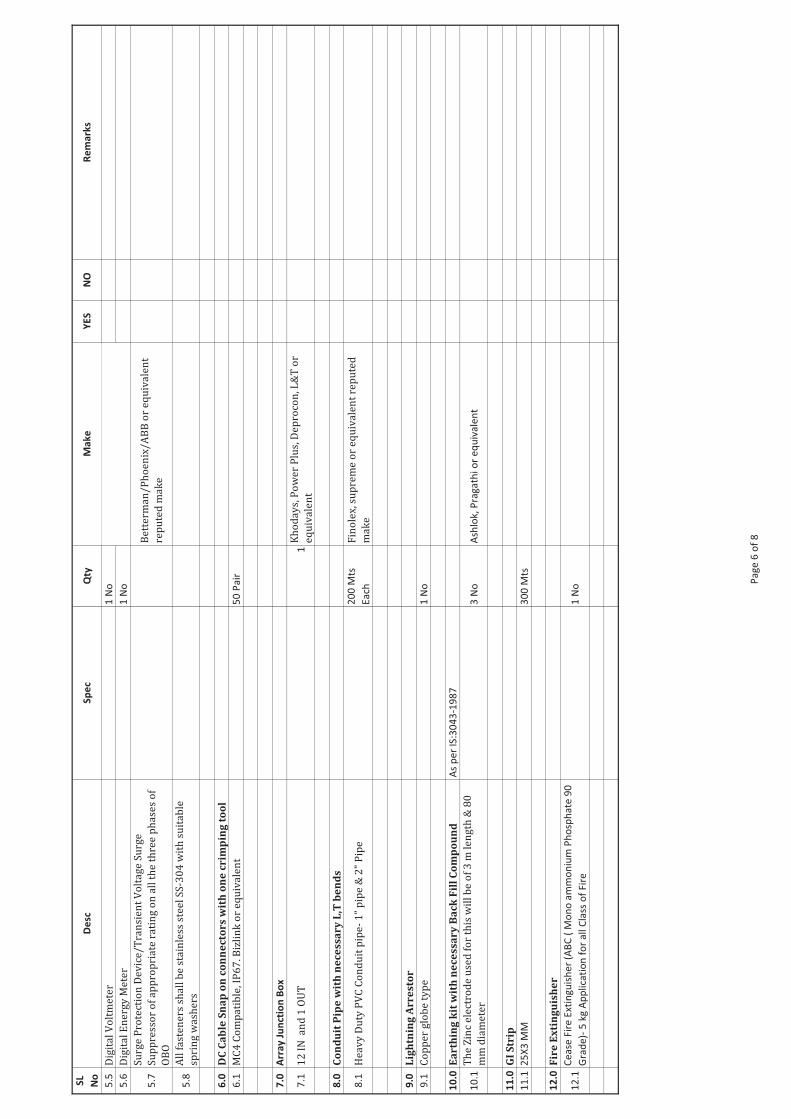
5.5
Dig
ita
l V
olt
me
ter
1 N
o
5.6
Dig
ita
l E
ne
rgy
Me
ter
1 N
o
5.7
Su
rge
Pro
tect
ion
De
vic
e/
Tra
nsi
en
t V
olt
ag
e S
urg
e
Su
pp
ress
or
of
ap
pro
pri
ate
ra
tin
g o
n a
ll t
he
th
ree
ph
ase
s o
f
OB
O
Be
tte
rma
n/
Ph
oe
nix
/A
BB
or
eq
uiv
ale
nt
rep
ute
d m
ak
e
5.8
All
fa
ste
ne
rs s
ha
ll b
e s
tain
less
ste
el
SS
-30
4 w
ith
su
ita
ble
spri
ng
wa
she
rs
6.0
DC
Ca
ble
Sn
ap
on
co
nn
ec
tor
s w
ith
on
e c
rim
pin
g t
oo
l
6.1
MC
4 C
om
pa
tib
le, I
P6
7. B
izli
nk
or
eq
uiv
ale
nt
50
Pa
ir
7.0
Arr
ay
Ju
nct
ion
Bo
x
7.1
12
IN
an
d 1
OU
T
1K
ho
da
ys,
Po
we
r P
lus,
De
pro
con
, L&
T o
r
eq
uiv
ale
nt
8.0
Co
nd
uit
Pip
e w
ith
ne
ce
ss
ar
y L
,T b
en
ds
8.1
He
av
y D
uty
PV
C C
on
du
it p
ipe
- 1
” p
ipe
& 2
" P
ipe
20
0 M
ts
Ea
ch
Fin
ole
x, s
up
rem
e o
r e
qu
iva
len
t re
pu
ted
ma
ke
9.0
Lig
htn
ing
Ar
re
sto
r
9.1
Co
pp
er
glo
be
ty
pe
1
No
10
.0E
ar
thin
g k
it w
ith
ne
ce
ss
ar
y B
ac
k F
ill
Co
mp
ou
nd
A
s p
er
IS:3
04
3-1
98
7
10
.1T
he
Zin
c e
lect
rod
e u
sed
fo
r th
is w
ill
be
of
3 m
le
ng
th &
80
mm
dia
me
ter
3 N
oA
shlo
k, P
rag
ath
i o
r e
qu
iva
len
t
11
.0G
I S
trip
11
.12
5X
3 M
M3
00
Mts
12
.0F
ire
Ex
tin
gu
ish
er
12
.1C
ea
se F
ire
Ext
ing
uis
he
r (A
BC
( M
on
o a
mm
on
ium
Ph
osp
ha
te 9
0
Gra
de
)- 5
kg
Ap
pli
cati
on
fo
r a
ll C
lass
of
Fir
e1
No
con
zerv
, Sch
ne
ide
r, L
&T
or
eq
uiv
ale
nt
ma
ke
Pa
ge
6 o
f 8
SL
No
De
scS
pe
cQ
tyM
ak
eY
ES
NO
Re
ma
rks
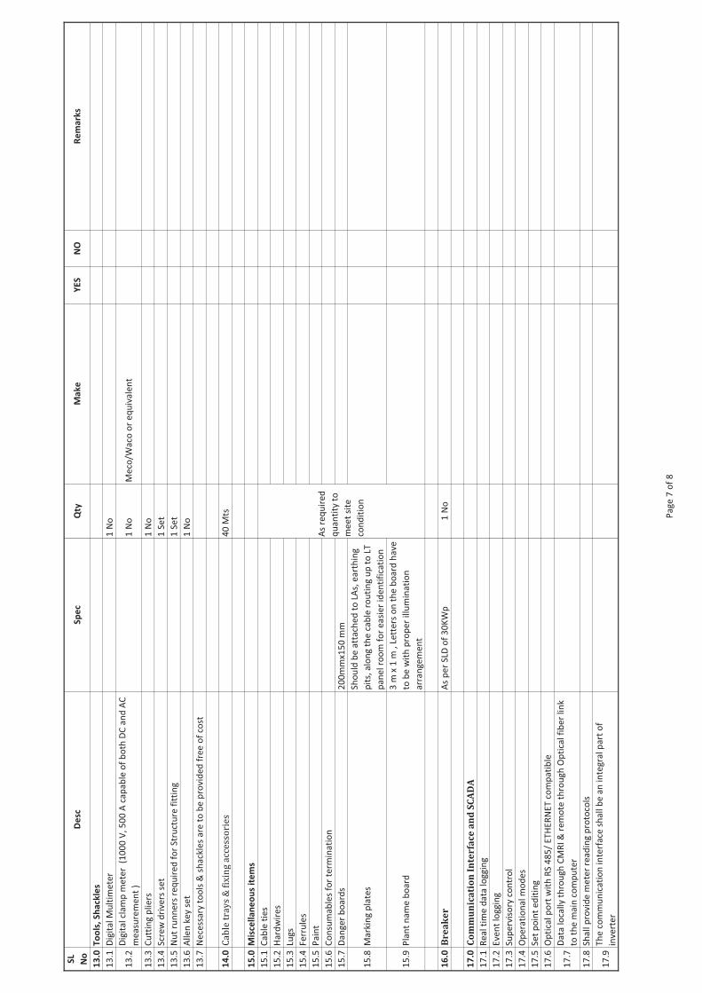
13
.0T
oo
ls,
Sh
ack
les
13
.1D
igit
al
Mu
ltim
ete
r 1
No
13
.2D
igit
al
cla
mp
me
ter
(1
00
0 V
, 5
00
A c
ap
ab
le o
f b
oth
DC
an
d A
C
me
asu
rem
en
t )
1 N
oM
eco
/Wa
co o
r e
qu
iva
len
t
13
.3C
utt
ing
pli
ers
1 N
o
13
.4S
cre
w d
rive
rs s
et
1 S
et
13
.5N
ut
run
ne
rs r
eq
uir
ed
fo
r S
tru
ctu
re f
itti
ng
1 S
et
13
.6A
lle
n k
ey s
et
1 N
o
13
.7N
ece
ssa
ry t
oo
ls &
sh
ack
les
are
to
be
pro
vid
ed
fre
e o
f co
st
14
.0C
ab
le t
ray
s &
fix
ing
acc
ess
ori
es
40
Mts
15
.0M
isce
lla
ne
ou
s it
em
s
15
.1C
ab
le t
ies
15
.2H
ard
wir
es
15
.3Lu
gs
15
.4F
err
ule
s
15
.5P
ain
t
15
.6C
on
sum
ab
les
for
term
ina
tio
n
15
.7D
an
ge
r b
oa
rds
20
0m
mx1
50
mm
15
.8M
ark
ing
pla
tes
Sh
ou
ld b
e a
tta
che
d t
o L
As,
ea
rth
ing
pit
s, a
lon
g t
he
ca
ble
ro
uti
ng
up
to
LT
pa
ne
l ro
om
fo
r e
asi
er
ide
nti
fica
tio
n
15
.9P
lan
t n
am
e b
oa
rd
3 m
x 1
m ,
Le
tte
rs o
n t
he
bo
ard
ha
ve
to b
e w
ith
pro
pe
r il
lum
ina
tio
n
arr
an
ge
me
nt
16
.0B
re
ak
er
As
pe
r S
LD o
f 3
0K
Wp
1 N
o
17
.0C
om
mu
nic
ati
on
In
ter
fac
e a
nd
SC
AD
A
17
.1R
ea
l ti
me
da
ta l
og
gin
g
17
.2E
ve
nt
log
gin
g
17
.3S
up
erv
iso
ry c
on
tro
l
17
.4O
pe
rati
on
al
mo
de
s
17
.5S
et
po
int
ed
itin
g
17
.6O
pti
cal
po
rt w
ith
RS
48
5/
ET
HE
RN
ET
co
mp
ati
ble
17
.7D
ata
lo
call
y t
hro
ug
h C
MR
I &
re
mo
te t
hro
ug
h O
pti
cal
fib
er
lin
k
to t
he
ma
in c
om
pu
ter
17
.8S
ha
ll p
rov
ide
me
ter
rea
din
g p
roto
cols
17
.9T
he
co
mm
un
ica
tio
n i
nte
rfa
ce s
ha
ll b
e a
n i
nte
gra
l p
art
of
inv
ert
er
As
req
uir
ed
qu
an
tity
to
me
et
site
con
dit
ion
Pa
ge
7 o
f 8
SL
No
De
scS
pe
cQ
tyM
ak
eY
ES
NO
Re
ma
rks
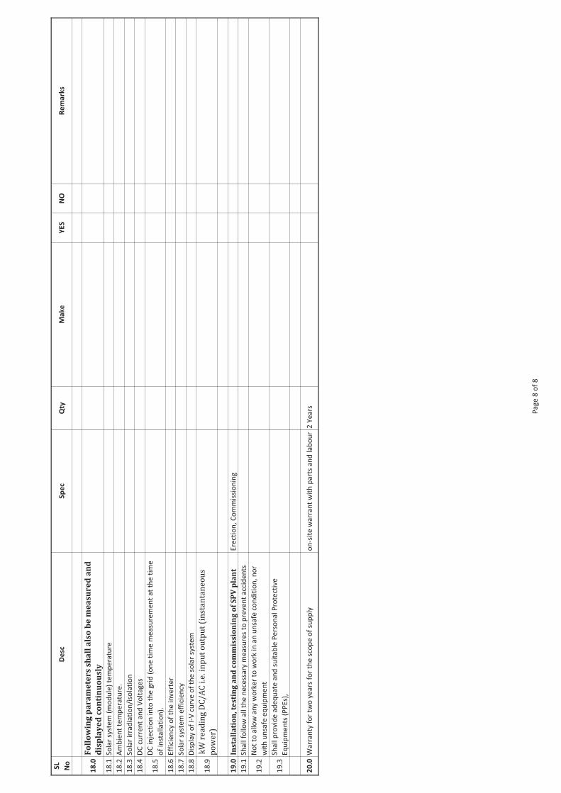
18
.0F
oll
ow
ing
pa
ra
me
ter
s sh
all
als
o b
e m
ea
sur
ed
an
d
dis
pla
ye
d c
on
tin
uo
usl
y
18
.1S
ola
r sy
ste
m (
mo
du
le)
tem
pe
ratu
re
18
.2A
mb
ien
t te
mp
era
ture
.
18
.3S
ola
r ir
rad
iati
on
/iso
lati
on
18
.4D
C c
urr
en
t a
nd
Vo
lta
ge
s
18
.5D
C i
nje
ctio
n i
nto
th
e g
rid
(o
ne
tim
e m
ea
sure
me
nt
at
the
tim
e
of
inst
all
ati
on
).
18
.6E
ffic
ien
cy o
f th
e i
nv
ert
er
18
.7S
ola
r sy
ste
m e
ffic
ien
cy
18
.8D
isp
lay o
f I-
V c
urv
e o
f th
e s
ola
r sy
ste
m
18
.9 k
W r
ea
din
g D
C/
AC
i.e
. in
pu
t o
utp
ut
(in
sta
nta
ne
ou
s
po
we
r)
19
.0In
sta
lla
tio
n, t
es
tin
g a
nd
co
mm
iss
ion
ing
of
SP
V p
lan
tE
rect
ion
, C
om
mis
sio
nin
g
19
.1S
ha
ll f
oll
ow
all
th
e n
ece
ssa
ry m
ea
sure
s to
pre
ve
nt
acc
ide
nts
19
.2N
ot
to a
llo
w a
ny w
ork
er
to w
ork
in
an
un
safe
co
nd
itio
n,
no
r
wit
h u
nsa
fe e
qu
ipm
en
t
19
.3S
ha
ll p
rov
ide
ad
eq
ua
te a
nd
su
ita
ble
Pe
rso
na
l P
rote
ctiv
e
Eq
uip
me
nts
(P
PE
s),
20
.0W
arr
an
ty f
or
two
ye
ars
fo
r th
e s
cop
e o
f su
pp
lyo
n-s
ite
wa
rra
nt
wit
h p
art
s a
nd
la
bo
ur
2 Y
ea
rs Pa
ge
8 o
f 8
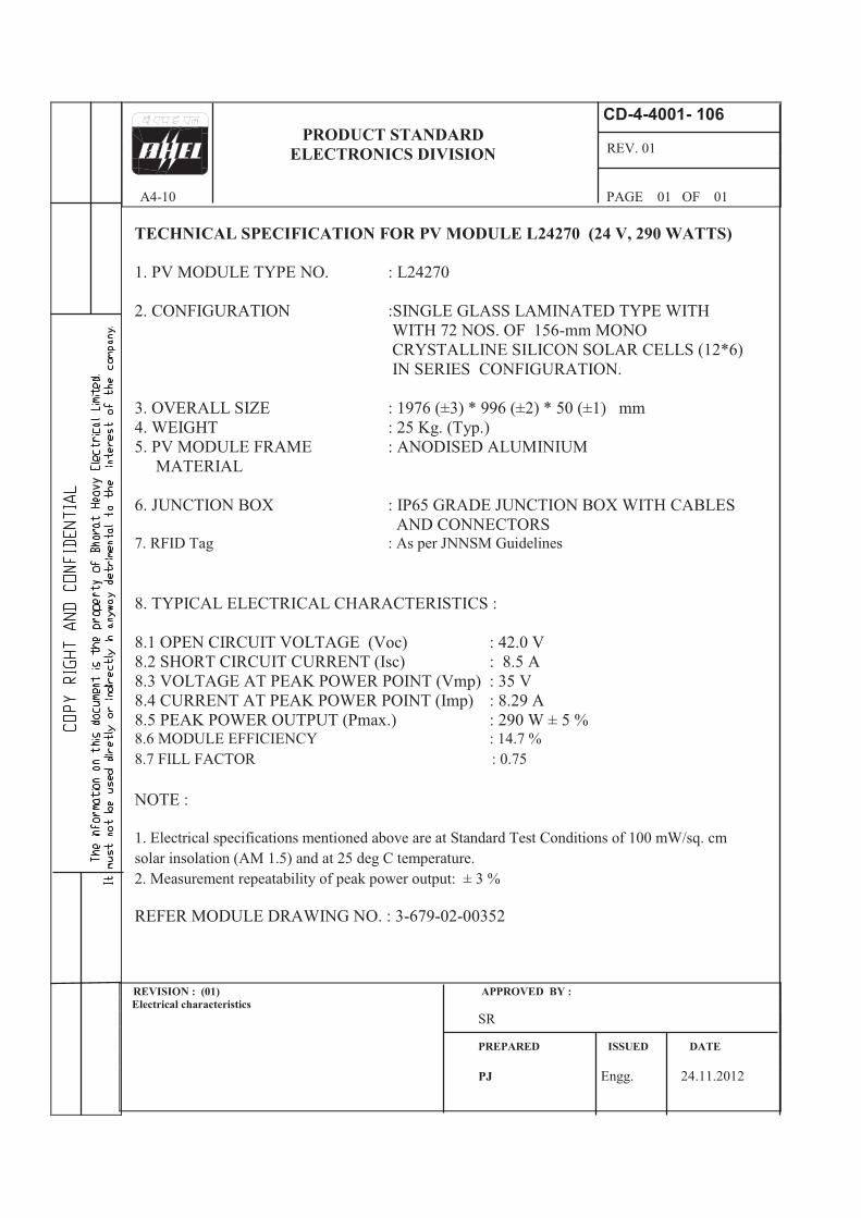
TECHNICAL SPECIFICATION FOR PV MODULE L24270 (24 V, 290 WATTS)
1. PV MODULE TYPE NO. : L24270
2. CONFIGURATION :SINGLE GLASS LAMINATED TYPE WITH
WITH 72 NOS. OF 156-mm MONO
CRYSTALLINE SILICON SOLAR CELLS (12*6)
IN SERIES CONFIGURATION.
3. OVERALL SIZE : 1976 (±3) * 996 (±2) * 50 (±1) mm
4. WEIGHT : 25 Kg. (Typ.)
5. PV MODULE FRAME : ANODISED ALUMINIUM
MATERIAL
6. JUNCTION BOX : IP65 GRADE JUNCTION BOX WITH CABLES
AND CONNECTORS 7. RFID Tag : As per JNNSM Guidelines
8. TYPICAL ELECTRICAL CHARACTERISTICS :
8.1 OPEN CIRCUIT VOLTAGE (Voc) : 42.0 V
8.2 SHORT CIRCUIT CURRENT (Isc) : 8.5 A
8.3 VOLTAGE AT PEAK POWER POINT (Vmp) : 35 V
8.4 CURRENT AT PEAK POWER POINT (Imp) : 8.29 A
8.5 PEAK POWER OUTPUT (Pmax.) : 290 W ± 5 % 8.6 MODULE EFFICIENCY : 14.7 %
8.7 FILL FACTOR : 0.75
NOTE :
1. Electrical specifications mentioned above are at Standard Test Conditions of 100 mW/sq. cm
solar insolation (AM 1.5) and at 25 deg C temperature.
2. Measurement repeatability of peak power output: ± 3 %
REFER MODULE DRAWING NO. : 3-679-02-00352
CD-4-4001- 106
REV. 01
A4-10 PAGE 01 OF 01
PRODUCT STANDARD
ELECTRONICS DIVISION
REVISION : (01) APPROVED BY :
Electrical characteristics
SR
PREPARED ISSUED DATE
PJ Engg. 24.11.2012
site