Embed Size (px)
Citation preview

Lockheed Martin Aeronautics Company
REVISION 30
CONTROLLED AND APPROVED BY:
Lockheed Martin Aeronautics Company
Supplier Quality Management
May 2016
IMPORTANT NOTICE: A hard copy of this document may not be the document currently in effect. The current version is ALWAYS the version on the LOCKHEED MARTIN network.
Supplier Tooling Manual
(Tool Manufacturing Specification - Material Control - 015)
TMS-MC-015
Applicable to
FORT WORTH – MARIETTA - PALMDALE
Sites
To the extent specified herein
TMS-MC-015 Revision 30
Page 2 of 104 01 April 2016
IMPORTANT NOTICE: A hard copy of this document may not be the document currently in effect. The current version is ALWAYS the version on the LOCKHEED MARTIN network.
* REVISED ** ADDED
_____________________________________________________________________________
TABLE OF CONTENTS
PART I. AIRCRAFT ITEMS AND TOOLING - SELLER REQUIREMENTS
*1.0 SCOPE Page 5
*2.0 TOOLING DEFINITIONS Page 6
*3.0 INTERCHANGEABLE-REPLACEABLE (I/R) Page 10
4.0 “TO MATCH” HOLE PATTERNS AND OTHER I/R FEATURES Page 10
*5.0 CONTROL OF RECORDS FOR BUYER FURNISHED TOOLING Page 10
*6.0 REPORTING REQUIREMENTS Page 11
*7.0 CONTROL OF BUYER-FURNISHED TOOLS Page 12
8.0 TOOL QUALITY CODE CATEGORIES Page 13 9.0 TOOL PROTECTION AND STORAGE REQUIREMENTS Page 14
*10.0 SHIPPING AND RECEIVING INSTRUCTIONS Page 14
*11.0 TOOLING PERIODIC INSPECTION AND RE-VERIFICATION Page 16
(PI/V)
*12.0 TOOLING PERIODIC INSPECTION AND RE-VERIFICATION Page 18
(PI/V) RECORDS 13.0 BUYER FURNISHED AND SELLER TO SELLER TRANSFER OF TOOLS Page 19 14.0 LOCKHEED MARTIN SUBCONTRACT SOURCE BOOKS Page 19
*15.0 BASIC PRINCIPLES FOR PRODUCTION USE OF TOOLING Page 19
PART II. MANUFACTURED SPECIAL TOOLING ONLY – SELLER REQUIREMENTS
1.0 GENERAL Page 20
*2.0 NON-RECURRING TOOL MANUFACTURING Page 20
3.0 SPECIAL TOOLING INSPECTION AND QUALITY REQUIREMENTS Page 21
*4.0 TOOL IDENTIFICATION AND SHIPPING REQUIREMENTS Page 23
5.0 PROCESS FOR TRANSFER OF TOOL DESIGNS FROM SELLER Page 24 TO BUYER 6.0 SEALING CRITICAL LOCATORS Page 24
*7.0 DUPLICATE TOOL MANUFACTURING Page 24
8.0 INTERCHANGEABLE- REPLACEABLE (I/R) DESIGN AND MANUFACTURING Page 24 9.0 NON (I/R) DESIGN AND MANUFACTURING Page 25
PART III. INTERNATIONAL SELLER REQUIREMENTS
1.0 GENERAL Page 26 2.0 CONTROL OF SUPPORT EQUIPMENT (SE), MANUFACTURING TEST EQUIPMENT (MTE) AND SPECIAL TEST EQUIPMENT (STE) Page 26 3.0 CHANGE AUTHORIZATION Page 27
*4.0 TOOLING PRACTICES FOR BUYER FURNISHED TOOLS Page 27
5.0 LISTINGS OF SELLER-FABRICATED/PROCURED ST OR STE Page 27 6.0 DRAWINGS, SKETCHES, TOOL DESIGNS, ETC. Page 27 7.0 CALIBRATION AND RE-CALIBRATION OF BUYER-FURNISHED Page 28 OR SELLER-FABRICATED STE 8.0 TOOLING USE AND TOLERANCE REQUIREMENTS Page 28

TMS-MC-015 Revision 30
Page 3 of 104 01 April 2016
IMPORTANT NOTICE: A hard copy of this document may not be the document currently in effect. The current version is ALWAYS the version on the LOCKHEED MARTIN network.
*9.0 QUALITY ASSURANCE REQUIREMENTS OF SELLER-OWNED Page 28
OR SELLER-FABRICATED PRODUCTION TOOLING
PART IV. APPENDICES APPENDIX A – REWORK, REPAIR AND COORDINATION GUIDE Page 29
APPENDIX A TABLE OF CONTENTS
*1.0 SCOPE Page 29
2.0 TOOLING PRECEDENCE OVER ENGINEERING STATEMENTS Page 29
*3.0 PRESERVATION OF BUYER FURNISHED TOOLS Page 33
4.0 STANDARD REPAIR TOLERANCES AND COORDINATION Page 36
5.0 STANDARD I/R IDENTIFICATION AND REWORK Page 39
6.0 “TO MATCH” HOLE PATTERNS AND OTHER I/R FEATURES Page 45
7.0 SHIPPING AND STORAGE CONTAINERS FOR BUYER FURNISHED TOOLS Page 46
8.0 BUYER FURNISHED TOOLING AND SELLER TO SELLER TRANSFER OF TOOLS Page 48
9.0 SET – UP PROCEDURE FOR FLOOR BASED ASSEMBLY JIGS Page 48
APPENDIX B – AIR FRAME TOOL CODES AND DEFINITION Page 51
LIST OF FIGURES
1. I/R TOOL DESIGN REQUIREMENTS Page 26
LIST OF FIGURES (Appendix A)
1. TYPICAL DS228 COMMON TOOL IDENTIFICATION PLAQUE Page 37 2. DOUBLE RAIL (INTERCHANGEABLE) Page 37 3. DOUBLE RAIL (REPLACEABLE, AND NON I/R, NET OR WITH EXCESS) Page 38 4. SINGLE RAIL SET-BACK TYPE (NON-I/R, NET OR WITH EXCESS) Page 38 5. PLUGGED TOOL HOLE EXAMPLE Page 39 6. TYPICAL TOOLING HOLE AND IDENTIFICATION OF TOOLING HOLES Page 39 7. TYPICAL PIN HOLE AND IDENTIFICATION OF PIN HOLES Page 39 8. DS-1017 I/R IDENTIFICATION LABEL Page 40 9. EXAMPLE OF I/R WEAR GROOVE INDICATORS Page 41 10. I/R HOLE IDENTIFICATION OPTIONS Page 41 11. I/R HOLE IDENTIFICATION EXAMPLE Page 42 12. PRODUCTION TOOL TO CONTROL TOOL Page 46 13. EXAMPLE OF “TO MATCH” HOLE PATTERNS AS DEFINED ON ENG. DRAWING Page 47 14. EXAMPLE OF TYPE I CONTAINER Page 48 15. EXAMPLE OF TYPE II-3 CONTAINER Page 48 16. EXAMPLE OF TYPE I-4 CONTAINER FOR LARGE TOOLS Page 49
TABLES (Appendix A)

TMS-MC-015 Revision 30
Page 4 of 104 01 April 2016
IMPORTANT NOTICE: A hard copy of this document may not be the document currently in effect. The current version is ALWAYS the version on the LOCKHEED MARTIN network.
UNPAINTED SURFACE COATING - Table 1.0 Page 35 COORDINATION PIN TOLERANCE – Table 2.0 Page 43 PRODUCTION ITEM TO PRODUCTION TOOL – Table 3.0 Page 44
APPLICABLE DOCUMENTS PM-4053 TOOLING MANUAL – Access limited due to Protected Data contained therein. Sellers contracted to fabricate or rework Special Tooling shall contact Buyer to submit access request. PM-4053 contains complete Buyer’s design, manufacturing and preservation requirements that are only briefly described or illustrated in this Manual. Seller shall refer to PM-4053 for complete specifications when this TMS Manual is imposed on a Purchase Order. See Part I, section 1.0. PURCHASE ORDER QUALITY APPENDIX “QX” – Supplier Quality Requirements PURCHASE ORDER QUALITY APPENDIX “QI” – Intra-Lockheed Martin Work Transfer Agreement (IWTA) Quality Requirements applicable to specific Lockheed Martin sites. FEDERAL AQUISITION REGULATION – FAR Subpart 2.101 Definitions “Special Tooling” FEDERAL AQUISITION REGULATION – FAR 52.245-1 Government Property FEDERAL AQUSITION REGULATION - DFAR 252.211-7003 IUID / RFID PART/DOCUMENT NUMBER POLICY (F-35 Program Standard) – 2YZA00996

TMS-MC-015 Revision 30
Page 5 of 104 01 April 2016
IMPORTANT NOTICE: A hard copy of this document may not be the document currently in effect. The current version is ALWAYS the version on the LOCKHEED MARTIN network.
PART I
AIRCRAFT ITEMS AND TOOLING - SELLER REQUIREMENTS
1.0 SCOPE
*1.1 This Tooling Manual “Manual” is applicable in its entirety when Quality Appendix QX or QI is
specified by this Purchase Order (PO). Any deviations from the requirements contained herein shall only be authorized by Buyer, in writing. This Manual contains the contractual requirements to properly control and maintain Seller Owned and Buyer Furnished Tooling in conjunction with all applicable documents listed or referenced in this Manual. The term Buyer Furnished Tooling comprises Special Tooling (ST), Support Equipment (SE), Manufacturing Support Equipment (MSE), Special Test Equipment (STE) and Manufacturing Test Equipment (MTE) for Buyer; as such terms are hereinafter defined in section 2.0, used to produce Items for Buyer. The term Seller Owned comprises any similar type tooling used in the manufacturing process for an item deliverable to Buyer. “Buyer’s assigned Quality Representative” shall mean the assigned Lockheed Martin Quality Representative responsible for on-site oversight of deliverable items, tool manufacturing, rework, repair, in-process acceptance and final acceptance of authorized tasks. 1.2 This Manual contains general and specific requirements that are applicable to airframe structural components as specified in this PO and other applicable documents. This manual is not applicable to Sellers of aircraft systems components that are subject to Automated Test Procedures (ATP). Tooling Manual PM-4053 takes precedence over all manufacturing and preservation requirements when conflicts exist between this Manual and PM-4053, if any. Right of access to PM-4053 is not necessary for all Sellers.
*1.2.1 Seller shall consult with Buyer and Buyer’s assigned Quality representative to determine
the need for PM-4053 access based upon PO requirements. Only Sellers contracted to perform airframe tooling task on a continual basis shall be granted access. Buyer may choose to forward hard copies of applicable sections from PM-4053 in lieu of granting access. 1.2.2 Seller shall perform authorized tool manufacturing, rework, alter, or repairs per this PO and this Manual. 1.2.3 The terms “Item” or its plural “Items”, “PO”, “Seller”, and “Buyer” as used herein, have the same meaning as the terms “Work”, “Contract”, “SELLER”, and “LOCKHEED MARTIN”, respectively.
*1.3 Seller shall immediately notify Buyer’s assigned Quality representative if and when Buyer authorizes
the manufacture, rework or repair of any ST to support delivery of Items as specified in this PO. Buyer’s assigned Quality representative shall determine the level of Buyer oversight required for in-process verification and or final acceptance of any such manufacturing, rework or repair of all tooling utilized in the manufacturing process for any deliverable Item. See Part II for Tool Manufacturing Requirements.
*1.4 Intra-Lockheed Martin Work Transfer Agreement (IWTA): The performing business unit (herein
referred to as Seller) shall be responsible for establishing and maintaining requirements, procedures and processes that ensure configuration control is maintained throughout the duration of this IWTA. See Part I, section 7.0 for specific Tool Control requirements.
*1.5 Seller’s quality management system shall ensure all Seller Owned Tooling, SE, MSE, STE and MTE
utilized for acceptance or validation of deliverable items to Buyer are calibrated and evidence of such calibration is maintained.

TMS-MC-015 Revision 30
Page 6 of 104 01 April 2016
IMPORTANT NOTICE: A hard copy of this document may not be the document currently in effect. The current version is ALWAYS the version on the LOCKHEED MARTIN network.
1.6 For the purpose of this Manual, “Parts Manufacturer” is defined as a Seller that manufactures parts, components, assemblies or items that are deliverable to the Buyer, LM Aero site, or facility. 1.7 For the purpose of this Manual “Tool Manufacturer” is defined as a Seller that manufactures aircraft tooling “only” that is deliverable to LM Aero sites, facilities, or as directed by PO. 2.0 TOOLING DEFINITIONS
*2.1. Special Tooling (ST) shall mean all jigs, dies, fixtures, molds, patterns, taps, gages or other
equipment and manufacturing aids, and replacements which are of such a specialized nature that without substantial modification or alteration, their use is limited to the development or production of particular supplies or Items thereof, or the performance of particular services. Reference FAR Subpart 2.101.
*2.1.2 Rework - Actions required on a tool when that tool fails to produce an acceptable feature
due to an out of tolerance condition or Buyer authorizes a modification to alter configuration.
*2.1.3 Repair - Actions required on a tool when that tool is broken, missing details or mechanisms
do not function properly.
*2.1.4 Non-Recurring Tools (NR) or Non-Recurring Engineering Tools (NRE) - tools authorized by
Buyer to facilitate manufacturing or delivery of Buyer items at a Parts Manufacturer and shall be considered Buyer Furnished Tooling when Buyer assigns an asset number for traceability. Access to PM-4053 is not granted for NR or NRE Tool manufacturing.
2.2 Modification Kit Tool (MKT) is categorized as ST and is used to update or modify aircraft assemblies and structures. 2.3 Tooling Tools means all gages used by Seller to control the fabrication or coordination of production tooling, holes, Interchangeable-Replaceable (I/R) features, critical mating points and surfaces or contours it represents. Tooling Tools are for tooling purposes only and shall not be used for production purposes. 2.4 Buyer Furnished Tooling means tooling that is either provided by Buyer or authorized by PO to be manufactured at Seller’s facility to support Buyer’s PO. Tooling that is authorized by PO to support delivery of items other than Tooling shall be considered Non-Recurring Tooling and shall be manufactured per this Manual in Part II, section 2.0, Non-Recurring Tool Manufacturing.
*2.5 Seller-Owned Tooling means all ST and Tooling Tools owned by Seller and used in the process of
fabricating, inspecting, assembling and coordinating of particular Items and/or tools as described in paragraphs 2.1 and 2.3. Seller-Owned Tooling is not to be confused with any form of Buyer Furnished Tooling. This is a tool owned by Seller and not owned by Lockheed Martin or Government agency.
*2.6 Special Test Equipment (STE) means either single or multipurpose integrated test items engineered,
designed, fabricated or modified to accomplish special purpose testing. STE consists of Items that are interconnected and interdependent so as to become a new functional entity for special testing purposes. STE excludes:
Consumable property
ST
Facility Items (except necessary improvements for installing STE)
Plant equipment Items used for general plant testing purposes
*2.7 Manufacturing Support Equipment (MSE) is equipment used in manufacturing operations to support,
manufacturer, test, or prove the functional operation of any end Item of Government Property. MSE consists of the following types of Items and shall be considered United States “U.S.” Government property:

TMS-MC-015 Revision 30
Page 7 of 104 01 April 2016
IMPORTANT NOTICE: A hard copy of this document may not be the document currently in effect. The current version is ALWAYS the version on the LOCKHEED MARTIN network.
*2.7.1 Support Equipment (SE) is equipment, required to make an Item operational in its intended
environment. SE includes the following:
Common and Standard SE – For use on more than one type item
Peculiar or Non-Standard SE – For use on a peculiar or specific item
*2.7.2 Manufacturing Test Equipment (MTE) is equipment, required for use in manufacturing
operations to conduct tests or prove the functional operation of a specific Item. MTE is peculiar to manufacturing in that it is not normally used by Buyer or customer to support the item in an operational environment.
*2.8 Control Media and Control Tools shall mean either electronic media or physical tools that control
configuration and typically are not used for production purposes. Such tools are categorized and may also control interchangeability or replaceability (I/R) of a specific feature or configuration. I/R Tooling is defined in Part I, section 3.0.
2.8.1 Master Tooling – Master tool gages used to establish dimensions and features during manufacture of Production Tools which control I/R and/or coordination points of production Items. Unless Buyer has provided Seller with prior specific written authorization to do so, Seller shall not use Master Tooling for production purposes, i.e., Item verification, drilling, trimming or forming.
2.8.2 Controlled Production Tooling – Tooling such as jigs and fixtures used to establish dimensions and features of Items and which control I/R and/or coordination points of those Items.
2.8.3 Electronic Data – Computer-generated electronic data used to establish dimensions and features during manufacture of production tools which control I/R and also used during fabrication of production Items for control of I/R features, e.g., trim, attach holes. 2.8.4 Inspection Gage/Fixture - Utilized to inspect features of parts or assemblies.
*2.8.5 Tooling Gage - Only used for dimensional control of other tooling.
*2.8.6 The following are additional types of Control Tools;
• COMG – Component Master Gage • FCGA – Facility Gage • MSFM/TOFM - Master Form/Tooling Form - For contour only. • MSFM/TOFM Lines shall be for reference only and Seller may revise or add these lines to
satisfy their production tool requirements without prior written authorization from Buyer. • MSGA – Master Gage, not to be used for Production “Part” validation • MSPE – Master Plate • PDSE – Production Samples (Tube) • TOGA – Tooling Gage • TOSE – Tooling Sample (Welded Tubes/Ducts) • Any tool identified by this PO and provided as a Control Tool
2.10 Manufacturing Engineering Data Model (MEDM) – An electronic Computer Aided Three-Dimensional Interactive Application “CATIA” model used to fabricate designed or non-designed tools. The MEDM may contain contour, reference lines, attach pattern, periphery, tooling holes, text, etc. in any combination for tool fabrication or the tool design. The MEDM may contain specific inspection points designated by Buyer. The inspection point coordinates can be recorded electronically and can be displayed on a paper plot of the MEDM. A Coordinate Measuring Machine “CMM” or other inspection device control program may be created from the MEDMs containing inspection point information defined by Buyer.
TMS-MC-015 Revision 30
Page 8 of 104 01 April 2016
IMPORTANT NOTICE: A hard copy of this document may not be the document currently in effect. The current version is ALWAYS the version on the LOCKHEED MARTIN network.
2.11 Production/Project Tools means jigs, fixtures, dies, and other tools made for use in manufacturing items in a production environment.
2.11.1 Convenience Tools are typically production tools and are Buyer Furnished Tools for the convenience of the Seller with an option to use for this PO. However, this type tool can also be a Tooling Tool to be used at the Seller’s convenience for tool coordination or production tool manufacturing. Seller shall validate condition and accuracy of such tools prior to use.
2.12 Electronic Supplier Problem and Resolution (e-SPaR) - This online system is available on the Buyer’s Supply Chain Management Homepage at http://www.lockheedmartin.com/us/aeronautics/materialmanagement.html and is the approved system for Seller to request information regarding PO requirements, including Engineering drawing clarifications, tool design clarifications and any related issue that does not pertain to a physical discrepancy within a tool.
2.12.1 Examples of such submittals or request, but are not limited to, request for Buyer to ship applicable coordinating tool to Seller for the purpose of accomplishing Production Tool to Master Tool coordination or clarifying language within this PO, Tool Design or Build Package.
2.13 Seller Aircraft Tooling Report (SATR) 2.13.1 A SATR is a document initiated by Seller to document a discrepant Buyer-furnished ST condition. Buyer shall reply with authorization for rework or repair, if required, of "out of engineering" discrepancies or conditions. 2.13.2 This online system is available on the Buyer’s Supply Chain Management Homepage and was created to provide Seller with a traceable electronic means of reporting ST discrepancies and achieving disposition authorization from Buyer’s program representative. 2.13.3 Access is granted by applying for an account on the Buyer’s Supply Chain Management Homepage at http://www.lockheedmartin.com/us/aeronautics/materialmanagement.html. Highlight “Quality Requirements” and select “Corrective Action”.
* 2.13.4 Seller shall initiate a SATR to document physical discrepancies, or requests for deviation
from specifications or special processes of Buyer-furnished or any Buyer authorized manufactured tool that is assigned an LM Aero asset number, including all rework, repair, or alter authorizations. See Part IV, Section 3.0 Preservation of Buyer Furnished Tools, for exceptions to SATR submittal.
*2.13.5 Seller shall make every attempt to correct any discrepancy discovered during any tool
manufacturing of Buyer Furnished tools to ensure any defect is corrected and the tool meets design requirements or manufacturing specifications and maintains contracted configuration, prior to submitting a SATR. The SATR shall affect Seller's Quality Rating.
2.13.5.1 SATR’s initiated to document the condition of tool upon receipt from Buyer or a worn or unusable condition shall not affect Seller’s Quality Rating.
2.13.6 SATR shall not be used to request deviation in materials specified per Tool Design of any ST. Material deviations shall be coordinated and authorized through Buyer and Program Representative prior to initiation of any manufacturing task.
2.14 Order of Precedence for Control Media
2.14.1 F-16 document 16PP1957 - "Order of Precedence for Control Media for Manufacture of the F-16" takes precedence over all engineering dimensional requirements where master tools conflict with engineering requirements.
TMS-MC-015 Revision 30
Page 9 of 104 01 April 2016
IMPORTANT NOTICE: A hard copy of this document may not be the document currently in effect. The current version is ALWAYS the version on the LOCKHEED MARTIN network.
2.14.2 F-22 document 5PD41327 – “Order of Precedence for Control Media for Manufacture of the F-22” provides direction for implementation and management of identified variations between engineering designs and F-22 Control Tooling. 2.14.3 F-35, C-130, C-5 and P-3 program documents for “Order of Precedence for Control Media” is illustrated in PM-4053, section 3.1. Seller shall request a hard copy from Buyer if access to PM-4053 is not granted.
2.14.4 Tooling precedence over engineering requirements for all Aeronautics programs is defined or illustrated in Part IV, section 2.0.
2.15 Tooling Manual PM-4053
2.15.1 Tooling Manual PM- 4053 is the Buyer’s Manufacturing Specifications for Tooling. PM-4053 is “Protected Information” and access can be granted only to Sellers authorized to perform manufacturing, rework or repair of “specific” Buyer Furnished tooling on a continual basis. Sellers authorized to perform manufacturing, rework or repair on a limited basis may not be granted access. Access can be granted as determined by Buyer’s Manufacturing Engineering organization. 2.15.2 To obtain access, Seller shall make a request to Buyer. Buyer will initiate the process of granting access by completing an internal Form # FWP5176 that is only found on the internal Intranet system. Buyer has the option to provide hard copies of applicable sections of PM-4053 as necessary to minimize the need for full access to this Protected Information by Parts Manufacturing Sellers if appropriate for minor rework, repair, alter, or manufacturing.
*2.15.3 Tool design and manufacturing requirements set forth in PM-4053 for tooling deliverable to
a Buyer are fully imposed when this Manual (TMS-MC-015) is referenced in a PO. 2.16 Tooling Used As a Media of Acceptance (MOA)
2.16.1 Any tool, including Shop Aid or Production Aid, Buyer Furnished, or Seller Owned, that is used to drill, locate, install, assemble, or used for product acceptance that does not have a subsequent dimensional inspection of the established feature within the same manufacturing sequence, shall be considered tooling used as a MOA and is subject to Periodic Inspection and Verification (PI/V) per Part I, section 11.
2.17 Key Characteristic (KC) is an attribute or feature whose variation has a significant effect on product fit, form, function, performance, service life or producability, which requires specific actions for the purpose of controlling variation.
*2.18 Sellers shall document all tooling used in the manufacturing process on the require FAI Inspection
Report, including Seller Owned, when Quality Clause Q2A, First Article Inspection is imposed on this PO, and shall report such tooling as required per Part I, sections 5.0 and 6.0 of this Manual.
*3.0 INTERCHANGEABLE- REPLACEABLE “I/R”
3.1 Seller shall comply with I/R requirements imposed by this PO or IWTA and shall place all production tools that controls an I/R feature into a periodic recall cycle as specified in this Manual. This is applicable to Buyer Furnished or Seller Owned tooling. Part IV of this Manual provides I/R and “To Match” coordination requirements. 3.2 Interchangeable Items – Items which are completely finished and have designed/controlled features which allow them to be installed, removed, or replaced without alteration, misalignment, or damage to installed or adjoining Items. Interchangeable Items require only attaching means (bolts, nuts, screws, pins,

TMS-MC-015 Revision 30
Page 10 of 104 01 April 2016
IMPORTANT NOTICE: A hard copy of this document may not be the document currently in effect. The current version is ALWAYS the version on the LOCKHEED MARTIN network.
etc.) to install. Interchangeable Items do not require any fabrication operations such as cutting, filing, drilling, hammering or forcing at the point of installation. 3.3 Replaceable Items – Items which are partially finished and have designed/controlled features which require alteration of the Items in addition to the normal application or methods of attachment at the point of installation. Such alterations are limited to specified areas and may include drilling, filing, trimming, bending, etc. 3.4 Interchangeable Category Items – Items which are typically designated Items which are attached by bolts or screws, readily removable and replaceable. Such Items are designed in such a manner that all like Items made within the engineering drawing tolerances will substitute one for another. Interchangeable Category Items are Items that are maintained by Seller through use of normal manufacturing methods and compliance with engineering drawing dimension tolerances, without the use of I/R Control Media. 3.5 Seller shall manufacture I/R production tooling, only from Buyer Furnished control media, e.g., Control Tools and Electronic Data, and shall identify all production tooling establishing an I/R feature of a deliverable item to Buyer as specified in Part IV of this Manual. 3.6 Seller shall place all I/R Production Tools into a Periodic Inspection recall cycle as specified in Part I, section 11.0 and 12.0 herein.
** 3.7 Marietta C-130 program utilizes “Production Design Outline” (PDO) in many manufacturing plans.
Producability Engineering utilizes the PDO, Form number GD1124 or GD1124a, to flow down specific controlled features for spares and IR requirements. PDO’s are not typically provided as part of an engineering package. PDO’s will establish the component Category (1-8) or Classification (I or R) along with specific controlled features, including initial tooling for both the item and interface planned at the time of creation. Tool Engineering and Planning Engineering interpret the PDO requirements in the creation of the special tooling and work instructions reflected in Production Operation Instruction Sheet (POIS) and Source Book documents. If a PDO is not provided, contact your Buyer via e-SPaR. Note: PDO may not be available for all detail parts and are not revised once created, thus a PDO may not reflect special tool revisions or changes since the creation of the PDO.
3.7.1 The tools specified in the POIS or Subcontract Source Book (SSB), if applicable, are considered the MOA, see par. 2.16 for MOA tool requirement and section 14.0 for SSB applications. The controlling feature of the tool is considered nominal unless identified otherwise. The acceptance tolerance falls into one of two situations based on engineering. If the part is shown as a singular component on the engineering drawing, the part feature is accepted to the engineering drawing tolerance in reference to the tool feature that produced it. If the part is shown as part of an installation on the engineering drawing, the part feature is accepted to one half of the installation tolerance in reference to the tool feature that produced it. There can be exceptions to these cases, but any exception is reflected by a Tool Set Up Drawing (TSUD) or special work instructions on the tool or from the POIS or Subcontract Source Book, as applicable. 3.7.2 C-130 hole-patterns or positions of singular holes are verified using applicable ‘bolt-to-hole’ tolerance analysis. For this method, calculations are based on Maximum Material Conditions (MMC) or the smallest hole-size and largest fastener diameter. Acceptance criteria is derived based on one half of the bolt to hole tolerance. For example; where the MMC bolt to hole-tolerance is .025” common to a mate joint, the maximum positional error for each mating component is .012”. Therefore, the hole in the singular part or assembly is verified to the MOA tool by means of a .025” undersized pin. This is equivalent to .012” on position. During this verification, the part or assembly is secured to the MOA tool with full sized pins at positions as far apart as practical to prevent movement. The most practical approach is to utilize check pins equivalent to the production fastener size through holes at minimum specified diameter. There can be exceptions to these guidelines, but these will be reflected to a Tool Set-up Drawing (TSUD) or special work instructions on the tool, from the POIS or Subcontract Source Book, as applicable.

TMS-MC-015 Revision 30
Page 11 of 104 01 April 2016
IMPORTANT NOTICE: A hard copy of this document may not be the document currently in effect. The current version is ALWAYS the version on the LOCKHEED MARTIN network.
4.0 “TO MATCH” HOLE PATTERNS AND OTHER I/R FEATURES 4.1 The term “To Match”, when specified on Buyer engineering drawings relative to hole locations, indicates that the dimensions including tolerances, even when met, may not necessarily ensure physical mating of Item hole patterns at the point of installation. Seller shall follow requirements in Part IV of this Manual.
5.0 CONTROL OF RECORDS FOR BUYER FURNISHED TOOLING 5.1 As a minimum requirement, Seller shall record the following information for property management control of Buyer Furnished tooling, or comply with FAR 52.245-1 if applicable to this PO:
Tool Number or Asset Number assigned by Buyer
Buyer-assigned Item number and “Also Use” Item number/dash number that the tool will fabricate
Tool Code
Purchase Order number (or other authorization) under which the tool was furnished to or fabricated by Seller
The Government or Commercial prime contract number indicated in this PO and, if applicable, type of Item (e.g., ST, STE, SE, MTE, etc.)
Serial number of the shipping document for tools received by Seller from Buyer or authorized party and all packing sheet information.
Tool location within “Seller’s” facility, Sub-Tier Seller’s facility, rework, progressive inspection, calibration, maintenance and acceptance dates
Copy of the completed Certified Property List CPL Form 11300 provided by Buyer (See Reporting Requirements in 6.0).
Indication that tool is accountable to Buyer
Authority for disposition of tools which are no longer in Seller’s possession
*5.2 Seller, on a current basis, shall maintain all Buyer furnished tool designs, sketches, photographs, and
schematic drawings used in the fabrication, testing, or calibration of tooling. Seller shall show tool manufacturing tolerances on the tool design. Seller shall provide Buyer disposition for this data, as requested, at the same time disposition for related tooling is given. 5.3 Prior to any tool fabrication, Seller shall notify Buyer assigned Quality representative, submit a copy of Seller’s tool designs or concepts for Seller-owned and supplemental tools, including casting and forging tools, to Buyer for review and approval of concept for applicable tooling. If Buyer deems it necessary, Buyer, through its program Manufacturing Engineering, will provide concept or design changes to Seller.
*6.0 REPORTING REQUIREMENTS
*6.1 In addition to FAR mandated inventory/survey requirements, Seller shall list only Buyer furnished
tools authorized by this PO on Buyer’s Certified Property List (CPL) Form 11300, which is available on the Buyer’s Supply Chain Management Homepage at http://www.lockheedmartin.com/us/aeronautics/materialmanagement.html under Quality Requirements. The CPL is the form utilized by Buyer to record the status and location of Buyer and Government owned property, all Seller Owned tools are exempt from being reported on the CPL Form.
TMS-MC-015 Revision 30
Page 12 of 104 01 April 2016
IMPORTANT NOTICE: A hard copy of this document may not be the document currently in effect. The current version is ALWAYS the version on the LOCKHEED MARTIN network.
6.1.1 CPL shall be processed as directed by Buyer whenever tooling is completed, received, reworked, or re-stamped, and when tooling is moved from the previously reported plant address. 6.1.2 The CPL shall be complete, current and include all Buyer furnished Tooling, e.g., Master Tools, Tooling Tools, Check Fixtures, Inspection Gages and Production Tools. Seller Owned tools are exempt from CPL reporting.
*6.1.2.1 For the F-35 program, the CPL shall also include the authorizing Production Non-
Recurring (PNR) number assigned by Buyer. See Part II, section 2.0 for tool identification requirements for PNR/NR type tooling.
6.1.3 The Seller shall sign and stamp the CPL and forward the completed Form to Buyer. 6.1.4 Invoices for tooling shall not be processed until CPL is provided to Buyer with identification completed per PO Appendix T (Special Tooling “All Programs” or FAR 52.245-1, whichever is applicable.
6.2 Certain types of tooling, as mutually determined by Seller and Buyer, are exempted from CPL reporting requirements. One example of exemption would be unique forging die tooling and potential Protected Seller designs and manufacturing processes. Refer to paragraphs 5.1 through 5.3 for inventory/record requirements.
*7.0 CONTROL OF BUYER-FURNISHED TOOLS
7.1 Seller shall acknowledge receipt of all tools, including ST, SE, MTE and STE, by the signature of an authorized representative of Seller on the CPL and return as requested by Buyer. Federal Acquisitions Regulation, FAR Part 45, 45.506, provides Sellers with specific instructions, as applicable to this PO.
7.1.1 Seller’s Quality Management System (QMS) shall provide calibration or testing procedures capable of verifying configuration control of Seller-owned or Buyer-furnished Tooling, SE, MTE and STE. 7.1.2 Seller’s QMS shall include identification and configuration control procedures for Buyer Furnished ST. 7.1.3 Seller shall provide verification of compliance upon request from Buyer or Buyer representative. 7.1.4 Seller shall control tool traceability by ensuring all tool identification labels, plaques and removable details of tool are stored, handled, used and transported appropriately to prevent loss of any items associated with Buyer Furnished Tooling.
**7.2 Seller shall manufacture, maintain and control tooling to the following requirements and other
requirements contained herein to control such tooling used to produce and maintain aircraft and aircraft components;
Property records of Buyer Furnished Tooling accurately maintained and identified.
Configuration of tooling must be maintained and documented.
Design and use of tooling must meet applicable Health and Safety requirements.
Tooling must be verified to design requirements prior to production use.
Non-conforming tooling must be controlled to prevent use without authorization.
Corrective action for non-conforming tooling must be completed in order to determine root cause of non-conformance.
Unauthorized alteration of tooling is not allowed.

TMS-MC-015 Revision 30
Page 13 of 104 01 April 2016
IMPORTANT NOTICE: A hard copy of this document may not be the document currently in effect. The current version is ALWAYS the version on the LOCKHEED MARTIN network.
Maintain records to provide evidence that the tooling meets applicable requirements.
Tooling must be properly stored in order to prevent damage.
Tooling with no manufacturing requirements (inactive) shall be processed for disposition through Buyer, if as applicable.
*7.3 Upon receipt of any Buyer furnished tool, Seller shall notify Buyer’s Quality Representative to witness
opening of container and visually inspect the tool and contents for completeness and/or damage. Sealed containers (Lead Wire Seal) indicate that the tool is a “Control Tool” and requires completing the accompanying documents inside the container.
7.3.1 Seller shall complete Form FWP-1209 “Tooling Gage Storage Record” accompanying Control Tools, Master Tools or Inspection Gages for Fort Worth furnished tools when opening or closing the container. 7.3.2 Seller shall make entry in “Tooling Inspection Record” (Form 1856-2) for Marietta Control Tools, Assembly Tools, or Master Tooling that are accompanied by such form. Note: Neither form is a requirement for inclusion with Production type Tools. Replacement form 1856-2 is accessible by hard copy only through a request from Buyer. 7.3.3 Seller shall enter discrepancies, if any, in the remarks column. If Seller does not receive the applicable form with the tool, Seller shall initiate an e-SPaR requesting the correct form. These forms are not available externally. Should one of these forms be missing from the container, Seller shall immediately make request for replacement forms from Buyer.
**7.3.4 In addition to completing the required form, Seller shall;
• Verify all details are placed accordingly in container • Verify tool is clean and free of rust or damaged • Verify all loose details are shored or secured accordingly • Verify all metal surfaces are oiled / prepared for storage
*7.4 In no case shall Seller attempt to rework, in any manner, Buyer furnished tooling without prior written
authorization from Buyer.
7.4.1 Seller shall review Buyer authorization (SATR disposition or PO revision) for repair and contact Buyer’s representative to discuss appropriate level of verification or oversight required by Buyer’s representative to ensure that rework has been completed. 7.4.2 All I/R tooling and tooling used as a media of acceptance/inspection shall require delta First Article Inspection (FAI) demonstrations upon completion of rework or repair, unless the reworked or repaired tool is coordinated to designated control media. Additional I/R and non-I/R repair, preservation and coordination guidance are provided, but not limited to, Part IV of this Manual.
*7.4.3 Seller shall initiate a SATR to receive Buyer authorization for any rework or repair of Buyer-
furnished ST. 7.5 Seller shall maintain Buyer Furnished tooling in a usable condition capable of producing the original, or any subsequent item configuration, including spares, unless changes made by Buyer’s engineering are retroactive to the original point of effectivity of Item. Seller shall accomplish this by fabricating other Control Media for its use, or from Buyer-furnished Control Media. 7.6 When Buyer authorizes rework or modification and when a tool is capable of producing earlier configurations, Seller shall re-identify the tool to the new configuration item number. When Buyer-authorized rework or modification will render a tool incapable of producing earlier configurations without
TMS-MC-015 Revision 30
Page 14 of 104 01 April 2016
IMPORTANT NOTICE: A hard copy of this document may not be the document currently in effect. The current version is ALWAYS the version on the LOCKHEED MARTIN network.
extensive alteration, Seller shall notify Buyer prior to continuing any rework and request additional specific instructions for tool rework, or for potentially manufacturing new additional tooling. 7.7 Seller shall request from Buyer, Form 11539 Loss, Theft, Damage & Destruction, (LTDD) when Government Property is lost, stolen, damaged, or destroyed and shall complete the form along with any supporting documentation.
*7.8 Seller shall submit an e-SPaR with itemized listing of any LTDD U.S. Government tooling to Buyer.
Seller shall also include the following information on the e-SPaR submission for LTDD tooling:
A narrative description of the incident and corrective action taken to prevent recurrence
Original Purchase Order number
Original Purchase Order line Item number
Original tool number – where applicable or for replacement of ST only
Original Tool Code – where applicable or for replacement of ST only
Original tool asset number (barcode number) – where applicable or for replacement of ST only
8.0 TOOL QUALITY CODE CATEGORIES 8.1 Seller shall fabricate all tools to the quality code stated in this PO. If no quality code is imposed or “Buyer Accept at Source” is not stated in this PO, Seller fabricated tools shall be quality Code 2 below and shall be identified as defined in Part II, paragraph 2.1.
8.1.1 Seller shall coordinate manufacturing of such tools with Buyer’s assigned Quality representative to establish applicable points of validation, inspection, coordination or verification, if any.
8.2 “Code 1” – These tools are made of the best and most durable practical materials available. They are capable of producing items with critical tolerances at an accelerated production rate without addition or changes in construction. However, duplicate tools may be required by Buyer in some cases. 8.3 “Code 2” – Incomplete or low production rate quality tools that can be revised at a later date to meet the needs of an accelerated production program (capable of being reworked to Code 1 tools). Combined operational tools comparable to Code 1 tools used for performing multiple operations. Tools that can be revised by separating them into items or sections to make one or more Code 1 tools if required by production scheduling. 8.4 “Code 3” – Permanent type tools made from moderately priced materials and used for low production rates or a limited number of ship requirements. These tools must be capable of holding blueprint tolerances. If production is greatly increased, it may be necessary to replace these tools when authorized to Code 1 or 2. 8.5 “Code 4” – Low production rate tools made of low cost materials. These tools are used for accomplishing emergency, temporary, or off-station production operations. They must be capable of making items or assemblies that will meet minimum quality control standards. When making Items with this type of tooling, a maximum amount of handwork, standard setups, layouts, etc. is permitted. 8.6 “Code 5” – Lowest cost tooling used for production operations. These tools are needed for making items or assemblies where it is impossible to make them by layout, handwork, standard tools, or setups. Use of handwork, standard clamps, etc., is permitted when finishing Items to meet engineering tolerances. 9.0 TOOL PROTECTION AND STORAGE REQUIREMENTS 9.1 Seller shall ensure its quality system maintains surveillance in order that Control Media is not abused or damaged while out of storage/shipping containers. Seller shall be responsible for Buyer Furnished

TMS-MC-015 Revision 30
Page 15 of 104 01 April 2016
IMPORTANT NOTICE: A hard copy of this document may not be the document currently in effect. The current version is ALWAYS the version on the LOCKHEED MARTIN network.
tooling while in Seller’s possession and shall take particular care when tools are being stored, handled, transported, loaded into and removed from jigs and fixtures. Preservation, storage and shipping container requirements are illustrated in Part IV of this Manual.
*10.0 SHIPPING AND RECEIVING INSTRUCTIONS
*10.1 Buyer shall specify shipping destination and mode of transportation for tools that are to be shipped
from any point of origin. 10.2 Seller shall contact Buyer’s Quality representative to schedule an appropriate time for witnessing the following;
Opening of tool packaging and container upon receipt of any Buyer furnished tool.
Packaging and closure of containers prior to shipment of any tool.
Seller’s QA or Buyer’s representative completing the Form FWP1209 or Form 1856-2 (Gage Storage Record) that accompanies Master Gages and specific Control Media.
10.2.1 If Buyer’s Quality representative is unavailable within two (2) business days to witness the opening or closure of any tool packaging or container, Seller’s QA shall fill out the Form FWP-1209 or Form 1856-2, if as applicable, on their behalf and pictures of tooling and packaging/containers shall be forwarded to Buyer’s Quality representative as proof of condition of each tool, packaging and containers.
*10.2.2 Seller shall completely fill out appropriate “Seller Airframe Tooling Declaration Form -
Receiving” and receive written concurrence from Buyer’s Quality representative that tools are in useable condition prior to being placed into service at Seller’s facility. (See NOTE below)
*10.2.3 Seller shall completely fill out appropriate “Seller Airframe Tooling Declaration Form -Shipping”
and receive written concurrence from Buyer’s Quality representative that tools are in useable condition prior to shipment from Seller’s facility. (See NOTE below) NOTE: The “Seller Airframe Tooling Declaration – Receiving” and “Seller Airframe Tooling Declaration – Shipping” forms are located on the external Supply Chain Management website at: http://www.lockheedmartin.com/us/aeronautics/materialmanagement.html under Quality Requirements > Forms. Note: FWP1209 or Form 1856-2 is not required for production type tools.
10.3 The following Master Tools and Gages require tool storage containers (wooden boxes) for storage and shipping and shall be sealed with wire lead seal stamped by Seller’s QA:
FCGA (Facility Gage)
FG/30E (Facility Gage) (MAR)
COMG (Component Master Gage)
MCG/24E (Master Control Gage) (MAR)
MG/14E (Master Gage) (MAR)
MHLT/26A (Master Hole Layout Template) (MAR)
MSPE (Master Plate)
MSGA (Master Gage)
COTG (Component Tooling Gage)
TOGA (Tooling Gage)
TOFM (Tooling Form)

TMS-MC-015 Revision 30
Page 16 of 104 01 April 2016
IMPORTANT NOTICE: A hard copy of this document may not be the document currently in effect. The current version is ALWAYS the version on the LOCKHEED MARTIN network.
10.4 Upon instructions from Buyer to prepare tools for shipment and prior to shipment, Seller shall note physical damage, if any, to any tool and shall document all such damage, if any, by submitting a SATR as specified in Part I, Paragraphs 2.12 and 2.13.
*10.5 Upon request from Buyer or Buyer’s Quality representative, Seller shall provide information relative
to the use of any Buyer furnished tool while in Seller’s possession. The following questions shall be required to be answered by Seller for each tool being shipped, prior to shipment;
1. Does the Seller use tooling for manufacturing or acceptance of product (yes/no). 2. Did the Seller digitize the tooling and subsequently use automated method of establishing
features, e.g., NC machine? 3. Did the Seller manufacture its own tooling to support or replace Buyer furnished tooling or digitized
data? 4. If any of the first three questions are yes, what product feature(s) does each tool control? 5. Is there any Buyer Furnished tooling that is not used in manufacturing or acceptance of product? 6. What is the current condition of the tooling? If damaged, was a SATR initiated? Is the SATR
open? Is the tooling being repaired, or refurbished, or is new tooling being manufactured? 7. Are the tools used to accomplish FAI and or Fit Check (if applicable), still utilized the same in the
manufacturing process at the end of contract? If no, explain all deviations. 10.6 Seller shall prepare tools for shipment utilizing the instructions throughout Part IV, Section 3.0 of this Manual. 10.7 Seller shall ensure tools are free of rust and appropriate rust preventives applied as specified in Part IV, Section 3.0 of this Manual. 10.8 Seller shall ensure container or packaging is appropriate per Part IV, Section 7.0 of this Manual. 10.8.1 Wired Lead Seals are required for all closures of Master or Control Tooling. 10.9 If movement of Control Media will affect Seller’s ability to meet a delivery schedule, Seller shall immediately notify Buyer. 10.10 Upon receipt of Buyer Furnished tools, Seller shall notify Buyer’s representative to witness any physical damage, if any, to any tool, and shall document all such damage, if any, by submitting a SATR as specified in Part I, Paragraphs 2.12 and 2.13.
*10.11 At such time as Buyer determines that Buyer-furnished tools located at Seller’s facility are to be
dispositioned; Buyer shall list the tools and forward the listing, as appropriate, to Seller and Property Management, Subcontract Control Department. Upon receipt of the completed listing, Seller shall process the listed tools as follows:
**10.11.1 Segregate the tools to a secured storage area. Notify Property Management
Subcontract Control of the specific location of the segregated tools and indicate the Seller representative that should be contacted regarding final disposition instructions.
10.12 Upon Buyer’s written notification and transfer of tool title from Buyer to Seller, Seller shall remove all evidence of ownership markings from tools and tool containers or render markings unrecognizable. This tooling identification removal includes, but is not limited to, the following:
Ownership markings on plaques
Barcodes
Steel stamping
Vibro-engrave etching
Paint markings

TMS-MC-015 Revision 30
Page 17 of 104 01 April 2016
IMPORTANT NOTICE: A hard copy of this document may not be the document currently in effect. The current version is ALWAYS the version on the LOCKHEED MARTIN network.
10.13 Seller shall reference FAR 45.506 - Identification for contractor requirements of U.S. Government-owned property. Seller shall exercise caution to ensure that Tool Code and part number identifications are not removed.
*11.0 TOOLING PERIODIC INSPECTION AND VERIFICATION (PI/V)
*11.1 PI/V shall be a Seller process comprising the cyclical verification of “Selected Tooling” used as a
media of acceptance for a feature(s) of an item. Seller shall document and complete PI/V, if such media exist, or as specified by PO. Once an item has completed a successful FAI or Fit Check, the PI/V cycle shall initiate. Exceptions to an annual re-verification requirement are defined in 11.5.
Selected Tooling is defined as any Buyer-furnished or Seller-owned tool used as a media of acceptance (inspection) for a feature of any item deliverable to Buyer, where the feature of the item established by this tool is not physically measured or inspected by other methods.
Example of Selected Tooling that would be placed into a PI/V recall cycle: A Drill Jig (production Tool) used to drill four holes in an aircraft part and subsequently this Drill Jig is also used to verify the same four holes spacing, location, diameter, and depth, and Seller is not employing any other verification or inspection method to verify these features in the aircraft part.
For the purpose of this Manual and specific to PI/V requirements, “annual” is defined as the duration of the PI/V cycle that shall not exceed one year from the previous date of PI/V.
Due to Legacy program manufacturing practices and variances between one Supplier’s equipment from another, some Non-Designed tools do not have designated control media and may fall into a PI/V category of visual verification. In this occurrence, Seller shall request appropriate instructions from Buyer and Program personnel to determine or validate the appropriate PI/V method for such tools via an e-SPaR. See Part IV of this Manual for additional Legacy tooling coordination information.
**Seller shall take appropriate actions to capture/record critical feature(s) of all Non-Designed
tools that do not have control media for PI/V if such tool is used as MOA. This data will aid in performing future PI/V.
Visual PI/V is defined in Section 11.5.
Example of, but not limited to, such tools appropriate for Visual PI/V would be ATT/19A, HRT/20A, DLT/11A, Form Block, Dies, or similar type tools.
11.1.1 Seller shall place all Buyer-furnished or Seller-owned Inspection Gages or Check Fixtures into a PI/V recall cycle, if such tools are used as the only means of acceptance for such features. An example of such tool would be an inspection/check gage that is used to validate contour, holes, cut-outs, etc., and is the sole source of validating that feature. 11.1.2 Seller shall place all tooling that controls I/R into a PI/V recall cycle. 11.1.3 Seller shall utilize the coordination tolerances provided in Part IV of this Manual and PM-4053 or applicable coordination tolerance between tools specified by Buyer’s Tool Design. 11.1.4 Seller shall place all tooling used as a media of acceptance that establish features with an engineering or tooling tolerance of +/- .XXX (.010) or tighter tolerance into a PI/V recall cycle.

TMS-MC-015 Revision 30
Page 18 of 104 01 April 2016
IMPORTANT NOTICE: A hard copy of this document may not be the document currently in effect. The current version is ALWAYS the version on the LOCKHEED MARTIN network.
Note: If tool design of “selected tooling” includes sheet with specific PI/V requirements, the features specified on the sheet shall be re-verified on an annual basis, including all other features established by the tool that are not verified by physical inspection or other measurement methods. 11.1.5 Seller shall place all tooling, designated by this PO to take precedence over engineering, into a PI/V recall cycle, and all critical features or Key Characteristics (KC’s) established by a tool shall be re-verified on an annual basis to maintain configuration control. See Part IV for precedence over engineering statements.
*11.1.6 Seller shall verify any feature of a tool, upon request by Buyer’s Quality representative, to
Tool Design or this PO requirement, if manufacturing discrepancies are documented and root cause and corrective action is requested by Buyer’s Quality representative. 11.1.7 Seller’s PI/V documentation shall be a unique record system controlling the annual re-verification of Buyer Furnished and Seller Owned production tools, check gages, and inspection gages. 11.1.8 Any deviations from these mandatory requirements for PI/V shall only be authorized by written authorization from Buyer by appropriate PO revision. 11.1.9 Seller shall verify the configuration integrity of Hammer Die’s, Form Die’s and other tools subject to high wear prior to and after each production run.
*11.2 Seller shall be responsible for establishing a PI/V procedure for Buyer-furnished or Seller-owned
tools used as a media of acceptance to produce Buyer items and present proof of administering these procedures to Buyer or Buyer’s Quality representative upon request. Tools designated by Buyer as Master Tooling or Tooling Tools and used for coordinating purposes only, do not require PI/V but do require unique preservation controls to ensure configuration and integrity of tools are maintained. Preservation, maintenance and standard repair specifications are illustrated in Part IV of this Manual.
11.2.1 Sellers working to an Intra-Lockheed Martin Work Transfer Agreement (IWTA) between Lockheed Martin Companies shall be responsible for establishing and maintaining PI/V requirements, a procedure and process that ensures configuration control is maintained throughout this IWTA.
11.3 Seller shall perform PI/V of Selected Tooling at Seller’s facility annually if specific instructions are not provided by PO or IWTA. Seller shall review tool history after each PI/V to determine whether tool performance has been such that subsequent periodic cycles can be increased, remain as scheduled or be reduced. Seller shall coordinate any deviations from the annual requirement through Buyer by initiating an e-SPaR and subsequently receiving authorization from Buyer’s Program Management. Seller shall receive deviation authorization only through PO revision.
11.3.1 Sellers working under an IWTA shall use Request for Engineering Action (REA) System, only if applicable. 11.3.2 Sellers working under an IWTA shall be responsible for control, preservation, PI/V and maintenance as defined in this manual and PM-4053 as applicable to Seller’s Quality Management System and IWTA.
11.4 Seller shall place all “Inactive” tooling used as a media of acceptance into storage and designate these tools as “Inactive”. Seller shall perform PI/V on all “Inactive” tools prior to their being returned to “Active” status. If inactive tools are no longer required, Seller shall notify Buyer and Property Management for disposition instructions.

TMS-MC-015 Revision 30
Page 19 of 104 01 April 2016
IMPORTANT NOTICE: A hard copy of this document may not be the document currently in effect. The current version is ALWAYS the version on the LOCKHEED MARTIN network.
11.5 With an exception to Sellers working to an IWTA, and only in the absence of designated Control Media, Seller shall accomplish PI/V by means of visual inspection in lieu of performing physical tooling coordination. Seller shall accomplish the visual PI/V using the below criteria:
Seller shall use “Fit Check Items” or originally manufactured Items to the maximum extent possible, if applicable.
Seller shall obtain an up-to-date quality history data file for items effected by applicable tooling, and perform a quality analysis relative to any discrepancies which may be tool related. Seller shall take appropriate action based on analysis results.
Seller shall perform a tool examination for obvious damage, excessive wear, and broken, loose, worn, or missing items, e.g., both integral and removable, bushings, pins, and clamps.
Seller shall immediately identify any adverse conditions revealed as a result of the above actions and request direction from Buyer by submitting a SATR or using the REA system, if applicable.
Seller shall determine any adverse effect on items in work in Seller’s inventory or delivered to Buyer; and take appropriate action to segregate, document, and notify Buyer.
Seller shall not consider shop floor planning operations, general review of tool prior to each use in a production environment or stamped off shop planning as evidence of performing PI/V.
11.6 Seller shall request from Buyer all necessary Tooling Tools to perform PI/V coordination to Control Media, if such Tooling Tools exist or if it is practical for movement for such coordination activity. 11.7 Seller’s digitization of Master Tooling or Tooling Tools is an acceptable alternative to Seller storing Master Tooling or Tooling Tools at Seller’s facility for coordination activity. Digitizing data is a method of retaining the Master Tooling features for coordination activity. Seller shall use this digitized data to perform acceptance of features of Buyer deliverable items. Digitized data, Master Tools, Tooling Tools, and Control Tools do not require PI/V. Digitized Data retains the same tolerances as the tool features it represents. CAUTION: Digitized data is acceptable for this PO only. Seller shall verify that any additional PO’s for the same deliverable items is to the latest revision for Master Tooling or Tooling Tools. Seller shall verify the digitized masters are to the latest configuration. When performing coordination or verification of a physical tool to digitized data, applicable tolerances apply as if performing a tool-to-tool coordination. Tolerance requirements are illustrated in Part IV of this Manual.
*12.0 TOOLING PERIODIC INSPECTION AND RE-VERIFICATION (PI/V) RECORDS
*12.1 Seller shall maintain a unique record for all tools requiring PI/V. Such record shall list:
Tool Ownership (Buyer Furnished/Seller Owned)
Buyer or Seller Tool Number
Buyer or Seller Tool Code, if available
Buyer-assigned part number
Next PI/V recall date
Quality acceptance verification (i.e., stamp)
Control Media used, if applicable, shall be recorded in the PI/V record
History of previous PI/V
Date of PI/V
PI/V check sheet (if applicable)
Inactive tools, if applicable
TMS-MC-015 Revision 30
Page 20 of 104 01 April 2016
IMPORTANT NOTICE: A hard copy of this document may not be the document currently in effect. The current version is ALWAYS the version on the LOCKHEED MARTIN network.
*12.2 Upon Buyer or Buyer’s Quality representative’s request, Seller shall present the PI/V record.
12.3 Seller shall update or revise the data in its PI/V record to meet the requirements of 12.1 on the next PI/V cycle of each tool. 13.0 BUYER FURNISHED TOOLING AND SELLER TO SELLER TRANSFER OF TOOLS 13.1 Sellers authorized by Buyer to ship tools to another Seller shall ship tools according to Buyer’s authorization and Part I, section 10.0 of this Manual. 13.2 Sellers authorized by Buyer to receive tools from another Seller shall re-verify Buyer transferred or Buyer Furnished tooling per tool type requirements in Part IV of this Manual and Part I, section 10.0 of this Manual. 14.0 LOCKHEED MARTIN SUBCONTRACT SOURCE BOOK 14.1 Subcontract Source Books (SSB) are unique and are only applicable to LM Aero-Marietta’s C-130 Program if specified by this PO and Buyer’s Statement of Work (SOW). Otherwise, the TMS Manual is fully imposed and shall take precedence when discrepancies exist between this Manual and the SSB, when Quality Appendix QX or QI is imposed, referenced, or declared by this PO. 14.2 Any deviation or exceptions shall be authorized only by C-130 Program Management and shall be incorporated by PO revision or amendment. Clarification or deviation request shall be submitted as illustrated in Part I, section 2.12.
*15.0 BASIC PRINCIPLES FOR PRODUCTION USE OF TOOLING
*15.1 Seller shall take action to ensure the following principles are followed;
Do Not Cut Lanyards or Remove Attached Details without authorization.
Do Not Alter Tools (e.g., No Tape, No Writing, No Plugging Holes Etc.).
Do Not Store Tools Anywhere Other Than Their Intended Location.
Do Not Store any Buyer furnished Tool outside without applying protective coatings and placed in appropriate container, if applicable.
Do Use Only Tools Approved For Production.
Do not use Master Tools For Production Use.
Do Not Use Broken or Incomplete Tools.
Do Not Mishandle or Damage Tools.
Do Not Use A Tool Unless Called Out In Shop Work Instructions.
Do Submit SATR for disposition of any worn, damaged, or Out of Tolerance condition.
END PART I

TMS-MC-015 Revision 30
Page 21 of 104 01 April 2016
IMPORTANT NOTICE: A hard copy of this document may not be the document currently in effect. The current version is ALWAYS the version on the LOCKHEED MARTIN network.
PART II
MANUFACTURED SPECIAL TOOLING - SELLER REQUIREMENTS
1.0 GENERAL – Part II of this Manual is applicable to all domestic and international Sellers that manufacture, rework, or repair ST, and is in addition to requirements defined in Part I. 1.1Buyer’s tool design and manufacturing specifications are defined in PM-4053. Only Sellers authorized by PO to perform manufacturing, rework, or repair of Buyer furnished tools are granted access to this Protected Data website. Seller shall contact Buyer for access authorization. See Part I, section 2.15 for instructions. 1.2 Design and manufacturing requirements for configuration control of F-35 tooling is strictly controlled through Program document 2YZA00996. Unique positioning of alpha and numeric characters within the part numbering designate specific information that should be used as instructions for applicability of such tools and part numbers. 1.3 International applicability of tool identification, the using country, and the control of configuration are defined within Program Document 2YZA00996.
*2.0 NON-RECURRING (NR) TOOL MANUFACTURING
* 2.1 Parts Manufacturers authorized to manufacture or procure tooling that facilitate delivery of items for
this PO, i.e., parts, components or assemblies, shall permanently identify all such tools as illustrated below. Item Unique Identification (IUID) and Radio frequency Identification (RFID) are required when imposed by this PO. If specific identification and ownership requirements are not defined by this PO, then Seller shall submit an e-SPaR to Buyer requesting assigned Asset number(s) and identify such tools per the following examples;
Buyer Part Number/Dash Number: Example – 16B1944-29, 5HF45776-103, 2WSJ12345A1
Buyer Asset Number: Example - D12345, M081234, J1234501 or as directed by this PO.
Ownership: Lockheed Martin or U.S. Government (as applicable) by this PO.
IUID or RFID per DFAR 252.211-7003 or as specified in this PO for F-35 Program only Note: If an authorized NR tool consists of multiple loose items, details or supplemental tools, Seller shall identify such items with the same asset number followed by appropriate “Part 1 of X”, etc. to minimize separation and loss of details. The use of DS228 Tool Identification Plaque’s for identifying such tools is prohibited.
*2.1.1 Seller owned tools shall be identified per Seller’s tool identification procedure and listed on
FAI Report per AS9102 and Buyer’s Q2A requirements.
**2.1.2 All NR tooling that controls features of Buyer’s deliverable item shall be listed on the FAI
Report per AS9102 and Buyer’s Q2A requirements. 2.2. All Special Tooling, tool sketches, diagrams and designs covered by this PO, whether furnished to Seller or acquired or manufactured by Seller or its Subcontractor(s), is the property of Buyer or the U.S. Government and shall not be used in the production, manufacture, or design of any article for any other use, unless Buyer consents in writing. Buyer shall not consent to the use of Government-owned Special Tooling without prior written U.S. Government consent.

TMS-MC-015 Revision 30
Page 22 of 104 01 April 2016
IMPORTANT NOTICE: A hard copy of this document may not be the document currently in effect. The current version is ALWAYS the version on the LOCKHEED MARTIN network.
2.3. Careful consideration should be used in determining NR tool types for this PO. Special Tooling should be limited to Quality Code 2 through 5 as defined in Part I, section 8.0, as Low Dollar, Non-Critical, Non-Complex, Non-I/R, or Non-designed, to minimize any potential manufacturing risk.
*2.4 Parts Manufacturers authorized to manufacture any tooling, shall immediately notify Buyer’s Quality
representative to determine appropriate level of Buyer Quality representative oversight throughout manufacturing and acceptance regardless of complexity or function listed below:
Complex/Controls Configuration - Example of a complex tool would be a tool used to establish a feature, e.g., Holes, I/R Holes, or surface or close tolerance dimensions. Example of a Control Tool would be a tool used for coordinating other tools that are used in the manufacturing process or a tool used directly as a gage or inspection media. Supplier shall coordinate manufacturing of such tools with Buyer’s Quality representative to determine appropriate level of oversight required during manufacturing and or final acceptance, if necessary, and such tools shall be placed into a PI/V recall cycle. Controls Interchangeability/Replaceability (I/R) –All I/R Tools require Seller to coordinate the manufacturing and I/R demonstration/validation prior to release for production use. Seller shall coordinate manufacturing of such tools with the use of Buyer Furnished Master Tool or Control Tool and Buyer’s Quality representative, to determine appropriate level of oversight required during manufacturing and final acceptance. Trial Run/Proof Load Required - Example would be a tool used at assembly and would require validation that it performs as designed to locate, clamp, attach, or support multiple flyable details or assembly hardware items as planned. Seller shall coordinate manufacturing and validation of such tools with Buyer’s Quality representative, if applicable. Non Complex Tools/Non (I/R)/Low Dollar, all similar categories – Example would be a holding or vacuum fixture used on a NC milling machine that is not used in establishing a feature. This fixture is simply used to hold an alloy billet while machining. Work Scaffolding or Work Stands, shop aids, etc. shall be considered Non Complex Tools. The manufacturing and application of such tools should still be reviewed by Buyer’s Quality representative during initial manufacturing planning, but formal or final acceptance is not required. Minimum Manufacturing Requirements Imposed Upon Seller-Built, Non Complex Tools – are specified in this Manual, located on the SCM External Home page under >Quality Requirements > Control Spec’s. http://www.lockheedmartin.com/us/aeronautics/materialmanagement.html
** REMAINING SECTION’S OF PART II ARE REQUIREMENTS APPLICABLE ONLY TO A SELLER
THAT DESIGNS AND BUILDS AIRFRAME TOOLING AND DELIVERABLE TO A LOCKHEED MARTIN
AERONAUTICS SITE FOR USE AT LOCKHEED MARTIN SITES. **
3.0 SPECIAL TOOLING INSPECTION AND QUALITY REQUIREMENTS – DELIVERABLE TOOLING 3.1 Seller shall comply with stress relief, annealing, welding, and non-destructive inspection (NDI) operations in accordance with PM-4053. Seller shall flow the following instructions in Purchase Orders to their sub-tiers:
Buyer identification number for Seller
Buyer identification number for Seller’s sub-tier (if applicable)
All applicable Buyer-imposed specifications
3.2 Unless otherwise stated in Buyer’s Build-to-Package “BTP”, CMM, theodolite, photogrammetry, calibrated machine probe, or laser tracking are the only acceptable methods for contour verification, and are the preferred methods for hole pattern verification. CMM inspection is the overall preferred method for verification. Exception: If the CMM output data is such that the data is not electronically transmittable to a

TMS-MC-015 Revision 30
Page 23 of 104 01 April 2016
IMPORTANT NOTICE: A hard copy of this document may not be the document currently in effect. The current version is ALWAYS the version on the LOCKHEED MARTIN network.
CATIA model for review, or calculations must be performed manually in order to complete the inspection activity (e.g., vector data must be manually calculated for hole locations), the use of theodolites or laser tracking when the data can be readily uploaded electronically to CATIA are then the preferred methods of inspection. 3.3 Inspection Grid Pattern: Unless otherwise stated in Buyer’s BTP or specified in PM-4053, Seller shall inspect surfaces requiring verification using the following grid pattern:
3.3.1 A maximum distance of two (2) inches between points along contour for complex and/or compound surfaces. There are no minimum distance requirements. 3.3.2 A maximum distance of six (6) inches between points for planar surfaces. There are no minimum distance requirements. 3.3.3 All authorized Tool Design activity shall be coordinated and reviewed as outlined for Sellers and Co-Producers in PM-4053, Section 2.5.
3.4 Seller shall not proceed to the next verification milestone without prior written authorization by Buyer’s Quality representative in the Progressive Inspection Log “PIL”, or an equivalent log. 3.5 Seller shall establish and maintain a quality system which requires the inspection of all dimensions of a tool. Seller’s QA shall log all three (3) place dimensions (2 place for metric) or any dimensions specifically identified for inclusion in Buyer’s BTP, into the PIL, but is not required to log one (1) and two (2) place dimensions, (1 place for metric) in the PIL. 3.6 Seller shall include a statement in the PIL to document inspection and acceptance of all one and two place dimensions (1 place for metric). 3.7 Seller shall document tooling anomalies, requests for deviation or waiver, and other non-conformances, if any, identified during or subsequent to Seller’s tool manufacturing and acceptance process by submitting a SATR. 3.8 Seller shall plan the following criteria as inspection points and milestones that Seller shall present or provide as verification to Buyer’s Quality representative prior to final acceptance, final approval or final certification, or as otherwise specified by this PO. The following criteria are not all inclusive and shall be reviewed and discussed between Seller’s and Buyer’s representatives upon Seller’s receipt of this PO.
Verify closure of all SATR’s and e-SPaR’s
Verify 95% Tool Design approval from Buyer, if applicable
Verify Tool Plaque is stamped in the correct blocks releasing the tool for Trial Run or Production use per PM-4053
Verify Special Processes, if applicable, are performed per PM-4053, i.e., NDI, Heat Treat, etc.
Verify paint application per PM-4053
Verify flow-down of requirements to sub-tier suppliers per Appendix QX
Verify the applicability of a “Delta” FAI or Fit Check requirement for all rework or repair authorizations
Verify coordination of tool, if applicable, to Control Tools per Tool Design and PM-4053
Verify all inspection data, electronic and mechanical, have been documented and prepared for shipment with tool, if applicable
Verify Tool identification is per this PO and PM-4053 as applicable
Verify ownership marking is per this PO and PM-4053 as applicable
Verify loose details are stored and shored per PM-4053
Verify loose details are identified per program requirements per PM-4053
Verify I/R markings are per PM-4053 and that Tool Design clearly identifies I/R features and flag notes are used for identifying these features per this Manual in Part II, section 8.0 for production tools

TMS-MC-015 Revision 30
Page 24 of 104 01 April 2016
IMPORTANT NOTICE: A hard copy of this document may not be the document currently in effect. The current version is ALWAYS the version on the LOCKHEED MARTIN network.
Verify I/R identification on tool contains mandatory I/R statement per PM-4053
Verify if PI/V identification is noted on tool plaque, if applicable
Verify Heat Thermal Survey applicability per PM-4053
Verify material certifications and Certificates of Conformance (CoC)
Verify PIL’s have been completed as required in this Manual
Verify applicable leak checks have been performed per PM-4053, as applicable
Verify fiberglass plies and resin are per PM-4053 requirements, if applicable
Verify potting compounds are used for bushing placement per PM-4053, if applicable
Verify all potted bushings coordinate to coordinating tool per PM-4053
Verify all hole and drill bushing identification is per Tool Design
Verify Shipping/Storage container per Tool Design and PM-4053, if applicable
Verify Shipping documents are correct per this Manual and Buyer’s Shipping Requirement PM-5010, or as specified by Buyer in this PO
Verify tool protection requirements have been accomplished per PM-4053 for shipment to final designation, e.g., Overseas, Domestic.
Verify a copy of Tooling General Purpose Record (TGPR) has been stamped as evidence of completion of rework instructions, if a TGPR was provided as instructions for rework task.
Verify IUID or RFID per DFARS 252.211-7003 and PM-4053 if applicable or as specified in this PO for F-35 Program only. See paragraph 4.2.1 below.
3.9 Seller shall stamp the DS228 Tool Identification Plaque as defined in PM-4053 for tool identification by placing Seller’s quality stamp and date in the Trial Run block if Trial Run Type I, II or III are specified on this PO. If Trial Run Type IV is specified on this PO, Seller shall place “N/A” in the Trial Run block and place Seller’s quality stamp and date in the Production block. Tool identification plaque requirements are fully illustrated in PM-4053, section 3.8. Trial Run is the process of verification that the tool functions as necessary to produce a part or assembly per engineering requirements in a production environment. 3.10 When this PO specifies that a Trial Run is to be accomplished either at Seller’s facility or site, Seller shall stamp the tool identification plaque as listed below. See Fig. 1. “Typical DS228 Common Tool Identification Plaque” in Part IV, section 3.0 of this Manual.
Type I Trial Run Required, Stamp/Date the Trial Run Block and leave Prod. Block blank
Type II Trial Run Required, Stamp/Date the Trial Run Block and leave Prod. Block blank
Type III Trial Run Required, Stamp/Date the Trial Run Block and leave Prod. Block blank
Type IV Trial Run Not Required, Stamp/Date the Prod. Block, enter “N/A” in Trial Run Block
Type V Trial Run Required at Co-producer facility, Stamp/Date as indicated above similar to Type I or II, leaving the Prod. Block blank until successful Trial Run has been completed.
3.11 Trial Run Type descriptions are as follows;
Type I - Verification that a tool, work instructions and required equipment produce a part/assembly to engineering requirements in a production environment. Verification is accomplished by using conventional inspection equipment (e.g., scales, calipers, micrometers).
Type II - Verification of the tool, work instructions and required equipment at critical operation steps. Used for tools that produce part features that are not verifiable by the use of conventional measuring equipment. Part features are normally verified to the tool that produced them. Tool function is verified (e.g., vacuum, clamps) to assure the tool functions as intended in a production environment.
Type III - Verify all parts fit in the tool without fouling or the tool applies to the part/assembly (formerly called “Proof Load” in Fort Worth).
Type IV – None required.
Type V – Trial run required at co-producer. This Trial Run type is accomplished by a co-producer using the co-producer’s processes to validate that a tool, work instructions and required equipment produces a part/assembly to engineering requirements in a production environment. No action is required by LM Aero to coordinate, manage, or implement this trial run type at the co-producer.

TMS-MC-015 Revision 30
Page 25 of 104 01 April 2016
IMPORTANT NOTICE: A hard copy of this document may not be the document currently in effect. The current version is ALWAYS the version on the LOCKHEED MARTIN network.
3.12 When Tool Trial Run is required for tools which have associated equipment (example: portable power equipment), Tool Trial Run of the equipment is required also.
*4.0 TOOL IDENTIFICATION AND SHIPPING REQUIREMENTS – DELIVERABLE TOOLING
4.1 Tool identification for Buyer tooling is controlled by PM-4053. Seller shall check for the latest revision of PM-4053 requirements by visiting the on-line revision history link located on the Buyer’s BTP website. 4.2 Seller shall identify each Seller-manufactured ST in a conspicuous place using a permanent method such as stamping, engraving, etching, stenciling, etc., as required, per PM-4053.
**4.2.1 When imposed by PO, Seller shall identify tooling with applicable IUID marking per
PM-4053 Section 3.8. See example illustration below;
IUID Example:
*4.3 To ensure applicable inspection data and acceptance reports remain with the tool once received at
Buyer’s facilities, Seller shall secure all technical, inspection and acceptance data reports in a sealed envelope. The sealed envelope shall include the following note on the outside of the envelope: “These documents to Remain with Tool – Do Not Remove”. 4.4 Seller shall package, preserve, and protect all tooling designated to be shipped overseas as directed in this PO and PM-4053, section 3.16. 5.0 PROCESS FOR TRANSFERRING TOOL DESIGNS FROM SELLER TO BUYER 5.1 Digital Data Transfer – The transfer of digital data between Seller and Buyer is controlled through Buyer’s BTP Computer Aided Design/Computer Aided Manufacturing (CAD/CAM) Engineering Data
DS957-2 Metal Frame
2-D data matrix; Incorporating Format 12 “TEI”
Lockheed Martin Provided
TMS-MC-015 Revision 30
Page 26 of 104 01 April 2016
IMPORTANT NOTICE: A hard copy of this document may not be the document currently in effect. The current version is ALWAYS the version on the LOCKHEED MARTIN network.
Transfer Group. Buyer shall identify Seller’s Points Of Contact (POC) for setup of digital data transfer capabilities and forward this information to Buyer’s BTP CAD/CAM Engineering Data Transfer Group. Buyer’s BTP CAD/CAM Engineering Data Transfer Group shall contact Seller’s POCs and identify required capabilities, data transfer site information, (including passwords, directory information, email notifications, and access controls), and how Seller will be notified of data transfer activities. 5.2 Hardcopy Data Transfer – Seller shall coordinate all hard copy transfer of designs through Buyer if required by this PO. 6.0 SEALING CRITICAL LOCATORS 6.1 Torque seal requirements for sealing tooling locators are defined by site and program as follows:
Fort Worth requirements: F-22A tooling – Pink All other tooling – Purple Marietta requirements: All Programs Tooling – Pink Palmdale requirements: All Programs Tooling – Pink
All torque seal applications that are not for sealing locators or critical locating features can be White.
*7.0 DUPLICATE TOOL MANUFACTURING
*7.1 Seller shall manufacture duplicates of Buyer’s tools, when authorized by Buyer, and shall verify that
the original Buyer tool matches the original tool design before proceeding with duplication task. 7.2 Seller shall notify Buyer if discrepancies exist between Tool and Tool Design as required in Part I, section 2.13.
8.0 INTERCHANGEABLE-REPLACEABLE “I/R” DESIGN AND MANUFACTURING 8.1 Seller shall design and manufacture all tooling containing I/R features as defined in PM-4053. 8.2 Seller of Buyer authorized “design and build” tooling shall design I/R tools as illustrated in Figure 1 and PM-4053 Section 2.4.

TMS-MC-015 Revision 30
Page 27 of 104 01 April 2016
IMPORTANT NOTICE: A hard copy of this document may not be the document currently in effect. The current version is ALWAYS the version on the LOCKHEED MARTIN network.
Figure 1. I-R Tool Design Requirements
9.0 NON INTERCHEABLE OR REPLACEABLE (I/R), DESIGN AND MANUFACTURING 9.1 Seller shall receive written authorization to design and manufacture tools, once submittal of design, sketch, drawing, concept or schematics have been approved by Buyer’s program personnel. 9.2 Seller shall notify Buyer’s Quality representative when written authorization has been received. Seller’s Buyer Quality representative shall jointly develop an applicable validation process of all special processes, critical dimensions, leak checks, or any unique point in the manufacturing process.
END PART II
TMS-MC-015 Revision 30
Page 28 of 104 01 April 2016
IMPORTANT NOTICE: A hard copy of this document may not be the document currently in effect. The current version is ALWAYS the version on the LOCKHEED MARTIN network.
PART III
INTERNATIONAL SELLER REQUIREMENTS
1.0 GENERAL 1.1 Part III is applicable to programs in which Buyer furnishes Seller with items or material to support Buyer’s BTP, and is in addition to the requirements of Part I and Part II of this manual.
*1.2 Fabrication requirements of ST, STE, and MKT by Seller or Seller’s sub-tiers to produce Buyer-
designed items and aircraft modifications, as specifically contracted by this PO, are defined in Part II of this Manual and controlled by PM-4053, Section 10.0. 2.0 CONTROL OF SE, MTE AND STE 2.1 Receipt of SE – Seller shall return a stamped copy of SE receiver to Buyer within five (5) working days upon receipt of SE.
2.1.1 Maintenance and repair parts for SE – Seller shall requisition maintenance and repair parts for the SE provided as MSE from Buyer. 2.1.2 Modification of SE provided as MSE peculiar modification of SE – Seller shall receive a tool order, a peculiar modification kit and written Buyer authorization. Upon completion of modification, Seller will return the stamped off / approved copy of the tool order to Buyer. 2.1.3 Time Compliance Tech Order “TCTO” modification of SE – Seller shall receive a TCTO modification kit and written authorization from Buyer authorizing Seller to install the kit. Upon completion of kit installation, Seller shall return a completed Letter of Certification “LOC” to Buyer.
2.2 Receipt of MTE – Seller shall acknowledge receipt of the CPL by signing and returning the original CPL to Buyer.
2.2.1 Maintenance and Repair parts for MTE – Seller shall requisition maintenance and repair parts for the MTE from Buyer. 2.2.2 Modification of MTE – Seller shall not perform modification on MTE without prior written authorization from Buyer.
2.3 Receipt, Maintenance and Modification of STE other than MTE Receipt – Seller shall acknowledge receipt of STE, if any, by signing and returning the original CPL to Buyer within five (5) working days after receipt of STE.
2.3.1 Maintenance and Repair Parts – Seller shall requisition maintenance and repair parts for STE from Buyer. 2.3.2 Modification – Seller shall not perform modification of STE without prior written authorization and direction from Buyer.
2.4 Disposition of SE, MTE and STE – Seller shall request disposition instructions from Buyer when SE, MTE, and STE become surplus or obsolete. 2.5 Seller shall verify condition of all ST, SE, STE, MTE, MSE and MKT upon receipt for damage and contents and immediately inform Buyer and Buyer’s Quality Representative of any damage or missing contents, e.g., loose details, designs, records or Forms.

TMS-MC-015 Revision 30
Page 29 of 104 01 April 2016
IMPORTANT NOTICE: A hard copy of this document may not be the document currently in effect. The current version is ALWAYS the version on the LOCKHEED MARTIN network.
2.6 Seller shall notify Buyer’s Quality representative as illustrated in Part I, section 10.0 (Shipping and Receiving Instructions) prior to receipt or shipment of any Buyer furnished tooling or equipment. 2.7 Seller shall Trial Run applicable ST as directed by this PO or as illustrated in Part II, section 3.0 of this Manual. Buyer may elect to provide hard copies of applicable sections of PM-4053 or PM-9003, section 20.41 for specific instructions. 3.0 CHANGE AUTHORIZATION 3.1 Seller shall not rework, repair, or in any way alter control tools without prior Buyer written authorization in this PO or in a SATR disposition with a revised CPL and tool drawings, if required, to rework or re-stamp control tools per PM-4053, section 10.0.
*3.2 Seller shall return to Buyer the stamped and signed Tool Rework Form document and revised CPL
upon completion of Buyer authorized rework or repair per PM-4053, section 10.0.
*4.0 TOOLING PRACTICES FOR BUYER-FURNISHED TOOLS – Category “A” tools are control tools
that establish dimensions and features of production tools which control I/R or coordination points of other production tools. Seller shall use these tools as Control Media only to fabricate production and inspection tools. The following is a list of the affected tools:
COMG – Component Master Gage
FCGA – Facility Gage
MSFM/TOFM - Master Form/Tooling Form. For contour only. Lines on MSFM/TOFM are for reference only and
Seller may revise or add these lines to satisfy their production tool requirements without prior written authorization from Buyer.
MSGA – Master Gage
MSPE – Master Plate
PDSE – Production Samples (Tube)
TOGA – Tooling Gage
TOSE – Tooling Sample (Welded Tubes/Ducts)
Any tool identified by this PO and provided as a control tool 5.0 LISTINGS OF SELLER-FABRICATED/PROCURED ST OR STE 5.1 Seller shall establish and maintain a part list and tool list, by manufacturer’s part number, of ST or STE fabricated or procured by Seller, as required by Buyer. Seller shall not include any Buyer-furnished ST or STE in the list(s). 5.2 Seller shall produce and maintain listings of all tools required to fabricate Federal Identification Item Number (FIIN) spare Items. 6.0 DRAWINGS, SKETCHES, TOOL DESIGNS, ETC. 6.1 Seller shall maintain Seller-owned or Buyer-furnished current tool designs, sketches, photographs, and schematic drawings used in the fabrication, testing, or calibration of tooling. Seller shall provide a disposition of this data at the same time disposition for related tooling is given, as requested by Buyer. 6.2 Seller shall ensure Seller’s STE drawings of any electrical, electronic, hydraulic or pneumatic type, at a minimum, consist of a schematic with component parts called out by characteristics or part number, including adequate calibration and operation instructions.

TMS-MC-015 Revision 30
Page 30 of 104 01 April 2016
IMPORTANT NOTICE: A hard copy of this document may not be the document currently in effect. The current version is ALWAYS the version on the LOCKHEED MARTIN network.
7.0 CALIBRATION AND RE-CALIBRATION OF BUYER-FURNISHED OR SELLER-FABRICATED STE 7.1 Seller shall develop and maintain a schedule for maintaining calibration of Buyer-furnished or Seller-fabricated STE. Seller’s schedule is subject to approval of Buyer’s representative and Seller shall ensure such schedule includes the following:
Name and function of test equipment
Serial or identification number of test equipment
Criteria or standard to which test equipment is checked
Frequency of test 7.2 Buyer shall determine mode of transportation for STE and make arrangements for shipment, when STE is required at another location. 8.0 TOOLING USE AND TOLERANCE REQUIRMENTS – Seller shall comply with the tool usage and tolerance requirements as defined in PM-4053, unless unique requirements are otherwise specified on the Statement of Work “SOW”, BTP, or this PO.
*9.0 QUALITY ASSURANCE REQUIREMENTS OF SELLER-OWNED OR SELLER-FABRICATED
PRODUCTION TOOLING
*9.1 Seller shall submit applicable data of all Seller-fabricated or Seller-owned production tooling to
Buyer’s Program Management for review and approval prior to release of tool for trial run or FAI. Such data may include, but is not limited to, engineering data, drawings, designs, Master Layouts (MEL), etc. In addition, Seller shall use data generated by Trial Run to satisfy Buyer’s FAI requirement, if witnessed by Buyer’s Quality representative or designated alternate. 9.2 Seller shall inspect all Seller-fabricated production tooling, which has been manufactured utilizing Buyer-furnished Control Media, by utilizing applicable tooling tolerances defined in PM-4053. 9.3 Seller shall inspect or re-verify subsequent parts produced utilizing Seller-fabricated production tooling to the criteria defined in PM-4053. 9.4 Seller shall ensure each Item manufactured with Seller-fabricated ST and STE is identified in a conspicuous place with the current part number and dash number, Tool Code, any peculiar tool number, the “Also Use” current part number (if applicable), or Engineering Change Notice “ECN”. Seller shall identify STE and MKT as “Property of USGOVT” and ST as “Property of Seller”, or as directed by this PO.
END OF PART III

TMS-MC-015 Revision 30
Page 31 of 104 01 April 2016
IMPORTANT NOTICE: A hard copy of this document may not be the document currently in effect. The current version is ALWAYS the version on the LOCKHEED MARTIN network.
* REVISED ** ADDED _____________________________________________________________________________
PART IV APPENDICES
APPENDIX A – REWORK, REPAIR AND COORDINATION GUIDE
APPENDIX TABLE OF CONTENTS
1.0 SCOPE
2.0 TOOLING PRECEDENCE OVER ENGINEERING STATEMENTS
3.0 PRESERVATION OF BUYER FURNISHED TOOLS
4.0 STANDARD REPAIR TOLERANCES AND COORDINATION
5.0 STANDARD I/R IDENTIFICATION AND REWORK
6.0 “TO MATCH” HOLE PATTERNS AND OTHER I/R FEATURES
7.0 SHIPPING AND STORAGE CONTAINERS FOR BUYER FURNISHED TOOLS
8.0 BUYER FURNISHED TOOLING AND SELLER TO SELLER TRANSFER OF TOOLS
9.0 SET – UP PROCEDURE FOR FLOOR BASED ASSEMBLY JIGS
**************************************************************************************
*1.0 SCOPE
1.1 Appendix A is applicable for all programs at all sites and is included in this Manual as specification guidance for the preservation, alter, rework, repair and coordination of Buyer-furnished tools when authorized by PO, and to define applicability of Special Tooling for specific Legacy aircraft parts, components, and assemblies.
*1.2 Appendix A is not all inclusive of tool maintenance, alter, rework, repair, and coordination
requirements. This Manual section is intended to be utilized in conjunction with the requirements set forth in PM-4053 when applicable. If Seller does not have access to PM-4053, Buyer is authorized to furnish hard copies of applicable sections for Seller’s use, only when necessary. 2.0 TOOLING PRECEDENCE OVER ENGINEERING STATEMENTS 2.1 References to PM-4053 within this section are provided herein for such use by Seller. Buyer may furnish hard copies of applicable sections of PM-4053 or referenced Program Documents. Any hard copy distribution shall be limited to and applicable to this PO only. 2.2 For C-130 and P-3 Programs, Control Tools shall define the nominal configuration for the features they represent. In most cases, the C-130 and C-5 Programs manage configuration control of Interchangeable and Replaceable (I-R) features by means of Master Control Tools. Upon manufacture and acceptance, these Master Control Tools establish the master product definition and take precedence over the Engineering Drawings for the features they represent. Production tooling produced and coordinated to such Master Control Tooling serves as the primary means for creating and accepting controlled product features. Reference PM-4053, section 3.1.3.5.

TMS-MC-015 Revision 30
Page 32 of 104 01 April 2016
IMPORTANT NOTICE: A hard copy of this document may not be the document currently in effect. The current version is ALWAYS the version on the LOCKHEED MARTIN network.
2.3 “For C-130 and C-5 programs, the furnished Special (Project) Tools shall be considered the Engineering definition of the features they control unless otherwise noted in this PO. Example of such tools would be an ATT, STFB, DJ, etc. If through usage, rejection and subsequent investigation, any such tool feature is found to produce results non-conforming to Engineering Drawing specifications, then the same must be reviewed for corrective action as necessary, unless it is created by program Master Control Tooling”. Reference PM-4053, section 3.1.3.5.
2.3.1 When a project tool is specified by this PO to control a feature of deliverable item(s) to Buyer, the same tool shall be considered the Media of Acceptance for that feature and configuration.
2.4 Order of Precedence for Manufacture of the P-3/CP-140 ASLEP Kit (LG05ER0167) provides direction for the implementation and management of variation between Engineering Drawings and Tooling (Control Media) for the P-3/CP-140 aircraft. Specifically, this document provides direction for policies and processes to resolve dimensional conflicts between Engineering Drawings and accountable Special (Project) Tools for all P-3 and P-3 derivative programs, including CP-140. This document is applicable to P-3/CP-140 ASLEP kit manufacturing at all LM Aero facilities and suppliers. Reference PM-4053, section 3.1.3.6.

TMS-MC-015 Revision 30
Page 33 of 104 01 April 2016
IMPORTANT NOTICE: A hard copy of this document may not be the document currently in effect. The current version is ALWAYS the version on the LOCKHEED MARTIN network.
2.5 Order of Precedence for Control Media for Manufacturing of the F-16 (16PP1957) defines the traceability established from released engineering design to the completed aircraft for the F-16 Program. In addition to describing this process, this document provides the policy and guidance for continued inspection to tooling media and continued corrective action wherein exterior and interior lines and surfaces of components of the aircraft are involved.

TMS-MC-015 Revision 30
Page 34 of 104 01 April 2016
IMPORTANT NOTICE: A hard copy of this document may not be the document currently in effect. The current version is ALWAYS the version on the LOCKHEED MARTIN network.
2.6 Order of Precedence for Control Media for Manufacture of the F-22. See document number 5PD41327, which defines the Order of Precedence to be utilized for control, acceptance, and corrective actions of F-22 designs, tooling, and parts.

TMS-MC-015 Revision 30
Page 35 of 104 01 April 2016
IMPORTANT NOTICE: A hard copy of this document may not be the document currently in effect. The current version is ALWAYS the version on the LOCKHEED MARTIN network.
2.7 Order of Precedence for Control Media for Manufacture of the F-35, which defines the Order of Precedence to be utilized for control, acceptance, and corrective actions of F-35 designs, tooling, and parts.
3.0 PRESERVATION OF BUYER-FURNISHED TOOLS
* 3.1 To ensure the preservation of Buyer furnished tools, Seller shall:
Provide adequate storage space to ensure Buyer furnished tooling is not abused, stacked, constrained, or uncontrolled in a manner that may contribute to a loss of configuration.
Maintain all Buyer furnished tools in a rust-free or non-contaminated condition before shipping, storing, or placing into production.
Prior to each use Seller shall check and replace worn or damaged bolts, nuts, washers, gaskets,
seals, missing or lost items without initiating a SATR, at no cost to Buyer.

TMS-MC-015 Revision 30
Page 36 of 104 01 April 2016
IMPORTANT NOTICE: A hard copy of this document may not be the document currently in effect. The current version is ALWAYS the version on the LOCKHEED MARTIN network.
Repot or replace loose or worn drill bushings and resurface worn or damaged Non I-R router guide
surfaces while in Seller’s possession when such conditions exist, at no cost to Buyer. Seller shall
not initiate a SATR for such anomalies or conditions unless directed by Buyer via a response to
eSPaR.
Submittal of an eSPaR or SATR shall only be required if the rework or repair task is excessive and
outside the expectations on normal tool maintenance and preservation or if a specified control tool
is required for coordination of a controlled feature of a Buyer furnished tool.
Use and store inside a building and handle with care at all times all fiberglass and composite tooling to prevent accidental damage to critical points, surfaces, holes, etc.
For fiberglass and composite tools stored in a controlled area other than 75 degrees +/- 10 degrees, Seller shall protect such tools from excessive adverse conditions of heat, cold, sunlight, and moisture. In addition, when fiberglass and composite tools are subject to temperatures outside these limits, use such tools only after a period of temperature stabilization.
Ensure a period of 24 hours stabilization for each 10 degree change from 75 degrees which is necessary to bring the tool back within the approved temperature limits, not to exceed 72 hours.
Fiberglass and composite tools in production shall have the caution label (DS-938) applied at the next rework or Periodic Inspection/Verification (PI/V) if applicable.
Apply a MIL-C-16173 Grade 2 (light machine oil) protective coating or equivalent to unpainted alloy surfaces if stored sheltered from the elements, and a MIL-C-16173 Grade 1 (cosmolene) protective coating or equivalent if stored exposed to the elements. This does not apply to F-35 Program when Conex Containers are used for overseas shipments.
3.2 Cleaning of tool surfaces prior to coating unpainted surfaces shall be by spraying the area to be cleaned with "Break-Free" cleaning solution (water base, soap, and alcohol solution), or moisten cheesecloth or clean cotton waste cloth with Break-Free and remove grease, oil, and other contamination from tool surfaces. Dry the tool with a clean cloth, or use dry compressed air on inaccessible areas. Finally wipe the area to be protected with cleaning solvent. Protective coating must be applied within 24 hours after cleaning. 3.3 Rust may be removed from "non-critical" tool surfaces by grinding, sanding, wire brushing, or Jet-Blast cleaned with dry ice. Rust may be removed from "critical" tool surfaces with a coarse cloth (Scotch-Bright). Wipe the residue from the affected surfaces with a clean cloth. 3.4 Seller shall comply with the following requirements from the Table for Unpainted Surface Coating for tool storage:
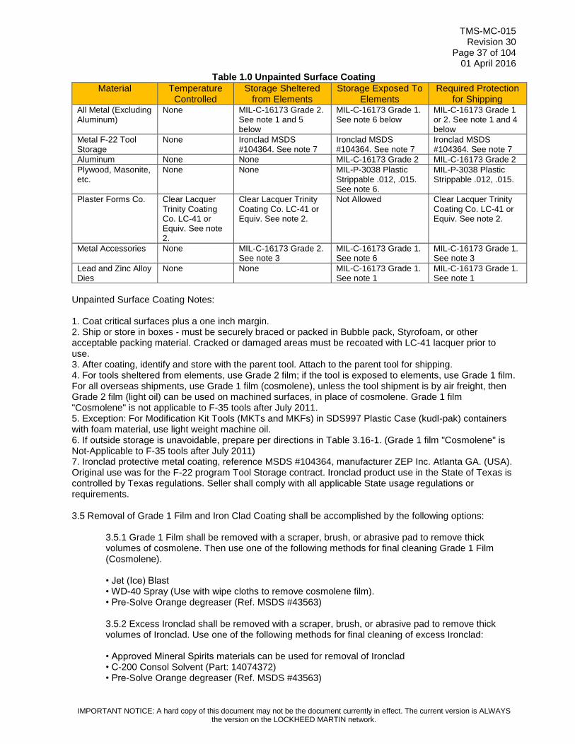
TMS-MC-015 Revision 30
Page 37 of 104 01 April 2016
IMPORTANT NOTICE: A hard copy of this document may not be the document currently in effect. The current version is ALWAYS the version on the LOCKHEED MARTIN network.
Table 1.0 Unpainted Surface Coating
Material
Temperature Controlled
Storage Sheltered from Elements
Storage Exposed To Elements
Required Protection for Shipping
All Metal (Excluding Aluminum)
None MIL-C-16173 Grade 2. See note 1 and 5 below
MIL-C-16173 Grade 1. See note 6 below
MIL-C-16173 Grade 1 or 2. See note 1 and 4 below
Metal F-22 Tool Storage
None Ironclad MSDS #104364. See note 7
Ironclad MSDS #104364. See note 7
Ironclad MSDS #104364. See note 7
Aluminum None None MIL-C-16173 Grade 2 MIL-C-16173 Grade 2
Plywood, Masonite, etc.
None None MIL-P-3038 Plastic Strippable .012, .015. See note 6.
MIL-P-3038 Plastic Strippable .012, .015.
Plaster Forms Co. Clear Lacquer Trinity Coating Co. LC-41 or Equiv. See note 2.
Clear Lacquer Trinity Coating Co. LC-41 or Equiv. See note 2.
Not Allowed Clear Lacquer Trinity Coating Co. LC-41 or Equiv. See note 2.
Metal Accessories None MIL-C-16173 Grade 2. See note 3
MIL-C-16173 Grade 1. See note 6
MIL-C-16173 Grade 1. See note 3
Lead and Zinc Alloy Dies
None None MIL-C-16173 Grade 1. See note 1
MIL-C-16173 Grade 1. See note 1
Unpainted Surface Coating Notes: 1. Coat critical surfaces plus a one inch margin. 2. Ship or store in boxes - must be securely braced or packed in Bubble pack, Styrofoam, or other acceptable packing material. Cracked or damaged areas must be recoated with LC-41 lacquer prior to use. 3. After coating, identify and store with the parent tool. Attach to the parent tool for shipping. 4. For tools sheltered from elements, use Grade 2 film; if the tool is exposed to elements, use Grade 1 film. For all overseas shipments, use Grade 1 film (cosmolene), unless the tool shipment is by air freight, then Grade 2 film (light oil) can be used on machined surfaces, in place of cosmolene. Grade 1 film "Cosmolene" is not applicable to F-35 tools after July 2011. 5. Exception: For Modification Kit Tools (MKTs and MKFs) in SDS997 Plastic Case (kudl-pak) containers with foam material, use light weight machine oil. 6. If outside storage is unavoidable, prepare per directions in Table 3.16-1. (Grade 1 film "Cosmolene" is Not-Applicable to F-35 tools after July 2011) 7. Ironclad protective metal coating, reference MSDS #104364, manufacturer ZEP Inc. Atlanta GA. (USA). Original use was for the F-22 program Tool Storage contract. Ironclad product use in the State of Texas is controlled by Texas regulations. Seller shall comply with all applicable State usage regulations or requirements. 3.5 Removal of Grade 1 Film and Iron Clad Coating shall be accomplished by the following options:
3.5.1 Grade 1 Film shall be removed with a scraper, brush, or abrasive pad to remove thick volumes of cosmolene. Then use one of the following methods for final cleaning Grade 1 Film (Cosmolene). • Jet (Ice) Blast • WD-40 Spray (Use with wipe cloths to remove cosmolene film). • Pre-Solve Orange degreaser (Ref. MSDS #43563) 3.5.2 Excess Ironclad shall be removed with a scraper, brush, or abrasive pad to remove thick volumes of Ironclad. Use one of the following methods for final cleaning of excess Ironclad: • Approved Mineral Spirits materials can be used for removal of Ironclad • C-200 Consol Solvent (Part: 14074372) • Pre-Solve Orange degreaser (Ref. MSDS #43563)

TMS-MC-015 Revision 30
Page 38 of 104 01 April 2016
IMPORTANT NOTICE: A hard copy of this document may not be the document currently in effect. The current version is ALWAYS the version on the LOCKHEED MARTIN network.
3.6 Seller shall provide storage containers for all Master Tooling and Inspection Gages fabricated with Buyer assigned tool numbers. Seller shall provide containers to specifications identified on the tool design. Seller shall ensure the containers provide adequate support and protection of tools from the environment and mishandling during movement. 3.7 Buyer furnished tooling identified per PM-4053 identification requirements prior to February 1, 2006 shall be acceptable indefinitely unless rework or repair authorization specifies attachment of a new DS228 Common Tool Identification Plaque for Fort Worth and Palmdale tools. The TNP001 Plaque is applicable for Marietta tools, if applicable per PM-4053, section 3.8. Such authorization will require the removal and discarding of any previous identification plaques or stickers with the following exceptions for Legacy Programs (C-130, C-5, P-3, F-16, etc.):
3.7.1 The use of multiple tool identification plaques on tools will be acceptable only if authorized by ESPaR request and disposition. Some Legacy Programs require the historical data contained in sequential tool identification plaques to remain attached to the tool indefinitely. 3.7.2 In all cases, the tool identification plaque with the most current information must be legible. If current tool identification plaque is worn and not readable, then a new common tool identification plaque would be required, if applicable by tool type and usage. Reference PM-4053, section 3.8 for specific information required in each block of plaque.
Fig. 1. Typical DS228 Common Tool Identification Plaque
(Highlighted blocks shall require an appropriate entry for each program)
4.0 STANDARD REPAIR TOLERANCES AND COORDINATION 4.1 For standard repair tolerances and coordination of Buyer-furnished tools, Seller shall:
Maintain allowable production tolerances on interchangeable Items produced/verified with controlled production tooling as illustrated in Figure 2.
Utilize a check pin for all I/R hole patterns to ensure patterns are made in accordance with the tool coordination tolerance tables included herein.
Utilize controlled production tooling to check and verify allowable production tolerances on interchangeable Items are from .010 smaller to .010 larger than the tool, as illustrated in Figure 8.
Utilize a check pin to check and verify the I/R hole pattern is made in accordance with the tool coordination tolerance tables included herein.

TMS-MC-015 Revision 30
Page 39 of 104 01 April 2016
IMPORTANT NOTICE: A hard copy of this document may not be the document currently in effect. The current version is ALWAYS the version on the LOCKHEED MARTIN network.
Figure 2. DOUBLE RAIL (INTERCHANGEABLE)
Verify replaceable and non-I/R part perimeters produced with production trim tools or check fixtures have allowable production tolerances from a maximum of .030 smaller, to a maximum of .030 larger than the tool, relative to the engineering drawing applicable feature tolerance as illustrated in Figure 3 and 4.
Verify perimeters are plus or minus .030 tolerances, unless otherwise stated on face of drawing. Example: An E.O.P. dimensioned as +.015, -.030 from a F.S., W.L., B.L. would apply. A "Tab" dimensioned as + or -.010 for overall width, would apply if stated on the drawing.
Utilize a check pin to verify all I/R hole patterns are made in accordance with the tool coordination tolerance table.
The use of supplemental tooling such as plaster splashes, fiberglass lay-ups and/or metal tools is authorized when a coordination tool is not available and such use is approved by program disposition via an e-SPaR. Such authorized tools shall require Limited First Run and or FAI article acceptance of the production items.
Figure 3. DOUBLE RAIL (REPLACEABLE, AND NON I/R, NET OR WITH EXCESS)
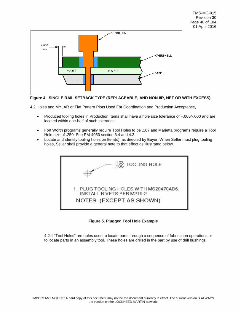
TMS-MC-015 Revision 30
Page 40 of 104 01 April 2016
IMPORTANT NOTICE: A hard copy of this document may not be the document currently in effect. The current version is ALWAYS the version on the LOCKHEED MARTIN network.
Figure 4. SINGLE RAIL SETBACK TYPE (REPLACEABLE, AND NON I/R, NET OR WITH EXCESS)
4.2 Holes and MYLAR or Flat Pattern Plots Used For Coordination and Production Acceptance,
Produced tooling holes in Production Items shall have a hole size tolerance of +.005/-.000 and are located within one-half of such tolerance.
Fort Worth programs generally require Tool Holes to be .187 and Marietta programs require a Tool Hole size of .250. See PM-4053 section 3.4 and 4.3.
Locate and identify tooling holes on Item(s), as directed by Buyer. When Seller must plug tooling holes, Seller shall provide a general note to that effect as illustrated below.
Figure 5. Plugged Tool Hole Example
4.2.1 “Tool Holes” are holes used to locate parts through a sequence of fabrication operations or to locate parts in an assembly tool. These holes are drilled in the part by use of drill bushings.

TMS-MC-015 Revision 30
Page 41 of 104 01 April 2016
IMPORTANT NOTICE: A hard copy of this document may not be the document currently in effect. The current version is ALWAYS the version on the LOCKHEED MARTIN network.
Figure 6. Typical Tooling Hole and Identification of Tooling Holes
4.2.2 “Pin Holes” are used in sheet metal parts for the purpose of locating part to perform necessary operations. Normally these holes are in a “tab” or in the excess area of a part. Size is “F” (.257) diameter unless otherwise specified.
Figure 7. Typical Pin Hole and Identification of Pin Holes
4.2.3 “Construction Holes” are holes placed in the tool for construction and/or inspection of the tool. These holes must be "soft plugged" in any tool which will be used for a drilling operation, before released for production use. Identified by painting green. Per Color Code Chart in PM-4053, section 4.3.
4.3 Mylar’s or any Buyer furnished Engineering Plot shall be utilized as directed by this PO, and tolerances shall be measured from the center of the plotted line the entire circumference of the part or feature within the part. Tolerance shall be the width of the line, regardless of line width for non-I/R tooling. Line width is usually .020 in width. I/R tooling tolerance shall be as noted on Tool Design or Engineering Drawing.
4.3.1. With this method of inspection, set the contour first with specified restraint in the established plane, if necessary, and then verify the Edge of Part (EOP) or feature to furnished Mylar or Plot. 4.3.2. The Plotted Line is the total tolerance for Non-I/R parts.
*5.0 STANDARD I/R IDENTIFICATION AND REWORK
5.1 Seller shall manufacture, rework, or repair I/R production tooling, only from Buyer Furnished control media, e.g., Control Tools and Electronic Data, and identify all production tooling establishing an I/R feature of a deliverable Item to Buyer as follows:
I/R shall be fabricated per applicable program I/R program document for production tools
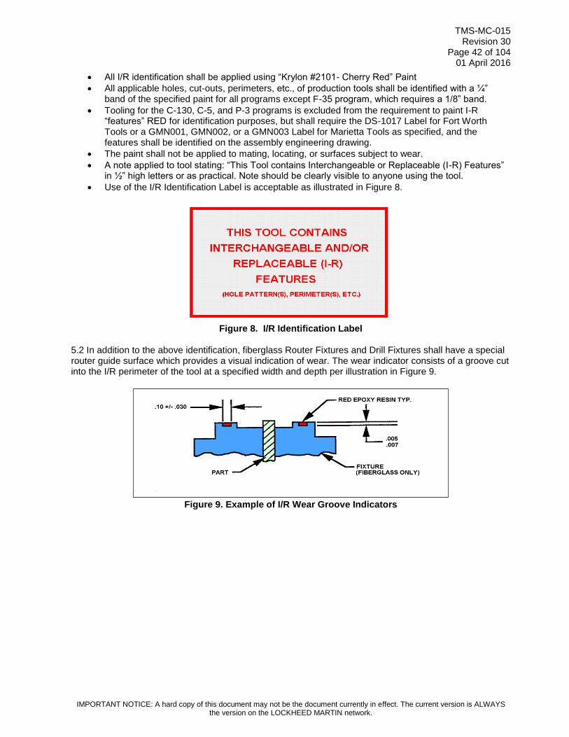
TMS-MC-015 Revision 30
Page 42 of 104 01 April 2016
IMPORTANT NOTICE: A hard copy of this document may not be the document currently in effect. The current version is ALWAYS the version on the LOCKHEED MARTIN network.
All I/R identification shall be applied using “Krylon #2101- Cherry Red” Paint
All applicable holes, cut-outs, perimeters, etc., of production tools shall be identified with a ¼” band of the specified paint for all programs except F-35 program, which requires a 1/8” band.
Tooling for the C-130, C-5, and P-3 programs is excluded from the requirement to paint I-R “features” RED for identification purposes, but shall require the DS-1017 Label for Fort Worth Tools or a GMN001, GMN002, or a GMN003 Label for Marietta Tools as specified, and the features shall be identified on the assembly engineering drawing.
The paint shall not be applied to mating, locating, or surfaces subject to wear.
A note applied to tool stating: “This Tool contains Interchangeable or Replaceable (I-R) Features” in ½” high letters or as practical. Note should be clearly visible to anyone using the tool.
Use of the I/R Identification Label is acceptable as illustrated in Figure 8.
Figure 8. I/R Identification Label
5.2 In addition to the above identification, fiberglass Router Fixtures and Drill Fixtures shall have a special router guide surface which provides a visual indication of wear. The wear indicator consists of a groove cut into the I/R perimeter of the tool at a specified width and depth per illustration in Figure 9.
Figure 9. Example of I/R Wear Groove Indicators

TMS-MC-015 Revision 30
Page 43 of 104 01 April 2016
IMPORTANT NOTICE: A hard copy of this document may not be the document currently in effect. The current version is ALWAYS the version on the LOCKHEED MARTIN network.
5.3 Seller shall identify F-35 I/R Holes with a 1/8” band of red paint around each hole or group of holes as illustrated in Figure 10 and Figure 11.
Figure 10. I/R Hole identification Options (All Fort Worth, Marietta: F-35 only)
Figure 11. I/R Hole Identification Example Only
5.4 Unique Tolerances for Legacy Program Tool Holes and Excess Material as specified below.
Non-Designed C-130 and P-3 tools that are controlled by Tooling Tools, shall have a hole size tolerance of +.001 to -.000, and Pin tolerance for such tools shall be -.0025 to -.0030 per PM-4053

TMS-MC-015 Revision 30
Page 44 of 104 01 April 2016
IMPORTANT NOTICE: A hard copy of this document may not be the document currently in effect. The current version is ALWAYS the version on the LOCKHEED MARTIN network.
or as specified by this PO or Tool Design, if any, or as directed by Buyers Program Engineering. Seller shall submit an e-SPaR when discrepancies exist.
Tooling holes may be authorized for detail parts manufacturing or location control during assembly and may or may not appear on engineering drawing. Sellers shall place tooling holes in detail parts only after authorization from Buyer’s Program Engineering to avoid potential interference with subsequent installations.
Material excess tolerance shall be per PM-4053 specification or as Buyer authorized through this PO to allow deviation from standard tolerance for part manufacturing. Standard tolerance of +.060/-.030 when material excess call out is .100 up to .250. For material excess greater than .250, the tolerance shall be +.100/-.060.
5.5 For Control Tool to Production Tool Coordination – Seller shall pin the control tool to the tool being coordinated with .0000 to .0005 undersize pins at four (4) locations reasonably close to the corners of the control tool. Seller shall inspect the remaining holes in accordance with pin tolerances shown in Table 2.0 for “Coordination Check of Control Tools”. 5.6 For Control Tool to Control Tool Coordination (Make New) – Seller shall install new control tool bushings utilizing pins with +.0000/-.0002 tolerance on diameter (Ref.: Transfer of hole pattern, Table 2.0). 5.7 For Control Tool to Control Tool Coordination (Rework) – During rework of control tools bushing, Seller shall install bushings utilizing pins with +.0000/-.0002 tolerance on diameter. (Ref.: Table 2.0, Transfer of hole pattern). 5.8 For Control Tool to Control Tool (Coordination Check Only) – Seller shall check the control tool back to the tool it was made from. During coordination checks of control tools, (Example: MSGA to TOGA), Seller shall pin four corner holes utilizing pins with +.0000/-.0002 undersize diameter. Ninety percent (90%) of the remaining holes are acceptable with .0000 to .0010 undersize diameter pins, and the remaining ten percent (10%) of the holes are acceptable with +.0000/-.0025 undersize diameter pins. 5.9 For Cross-Coordination of Control Tools – When duplicate control tools are fabricated, Seller shall cross-coordinate control tools in accordance with Table 2.0 "Coordination Check of Control Tools" to ensure compatibility. 5.10 For Bushing Installation – During the manufacture of new tools and reworks, Seller shall utilize tooling pins with +.0000/-.0002 tolerance to install all tooling bushings (ref.: Table 2.0 and Table 3.0, Transfer of hole pattern). 5.11For Inspection of Control Tool Bushing Wear – Seller shall inspect control tool bushings to ensure the maximum wear is limited in accordance with Table 1.0 and Table 2.0. Seller shall not use any control tools where bushing wear exceeds the maximum wear tolerance of +.0010 on the inside diameter. 5.12 For tool inspection requirements of I/R tool coordination (applicable to new make, rework, and coordination orders), Seller shall only utilize check pins which are AISI01 tool steel with a heat treat callout of RC 55-65 for pins with a diameter of .2500 or larger, and a RC 38-48 for pins with diameters smaller than .2500.
*5.13 I/R features shall be identified on the Tool Design with flag notes. For I/R tools designed after
01/01/2006, the I/R features will be shown or referenced on the last sheet of the Tool Design to facilitate tool fabrication, rework, and Periodic Inspection/Verification (PI/V). For the C-130, C-5, and P-3 Programs, I/R features that are controlled by the tool will be identified by the Production Design Outline (PDO) and will not be identified on the Tool Design. See Part I, Section 3.0, par 3.7.

TMS-MC-015 Revision 30
Page 45 of 104 01 April 2016
IMPORTANT NOTICE: A hard copy of this document may not be the document currently in effect. The current version is ALWAYS the version on the LOCKHEED MARTIN network.
Table 2.0 Coordination Check of Control Tools
Table 2.0 Coordination Check of Production Tools
HOLES UNDER .250 STRAIGHT PINS HOLES .250 AND OVER
Nominal +.0001/+.0004
Nominal +.0000/-.0002
Nominal +.0001/+.0010
Nominal -.0015/-.0020
Transfer of Hole Pattern
Bushing I.D. Tolerance
Pin Tolerance
Cross Coordination /
Coord. Check of
Control Tools
Bushing I.D. Tolerance
Pin Tolerance
Nominal +.0001/+.0006
Nominal +.0000/-.0002
Nominal +.0001/+.0010
Nominal -.0020/-.0025
STEP PINS
Nominal +.0001/+.0004
Nominal +.0000/-.0002
Nominal +.0000/-.0002
.0005 Max
Nominal +.0001/+.0010
Nominal -.0000/-.0002
Nominal -.0015/-.0020
Transfer of Hole Pattern
(New Make)
Bushing I.D. Tolerance
Lg. Dia. Pin Tolerance
Sm. Dia. Pin Tolerance
Concentricity
Cross Coordination /
Coord. Check of
Control Tools
Bushing I.D. Tolerance
Lg. Dia. Pin Tolerance
Sm. Dia. Pin Tolerance
Nominal +.0001/+.0006
Nominal +.0000/-.0002
Nominal +.0000/-.0002
.0005 Max
Nominal +.0001/+.0010
Nominal -.0000/-.0002
Nominal -.0020/-.0025

TMS-MC-015 Revision 30
Page 46 of 104 01 April 2016
IMPORTANT NOTICE: A hard copy of this document may not be the document currently in effect. The current version is ALWAYS the version on the LOCKHEED MARTIN network.
Table 2.0 Coordination Check of Production Tools
Table 2.0 Coordination Check of Production Tools (continued)
HOLES UNDER .250 STRAIGHT PINS HOLES .250 AND OVER
Nominal +.0001/+.0004
Nominal +.0000/-.0002
Nominal +.0001/+.0004
Nominal +.0001/+.0010
Nominal -.0020/-.0025
Transfer of Hole Pattern
(New Make)
C/T Bushing I.D. Tolerance
Pin Tolerance
P/T Bushing I.D. Tolerance
Coordination Check of
Control Tools to Prod. Tools
Bushing I.D. Tolerance
Pin Tolerance
Nominal +.0001/+.0006
Nominal +.0000/-.0002
Nominal +.0001/+.0006
Nominal +.0001/+.0010
Nominal -.0030/-.0035
STEP PINS
Nominal +.0001/+.0004
Nominal +.0001/+.0004
Nominal +.0000/-.0002
Nominal +.0000/-.0002
.0005 Max
Nominal +.0001/+.0010
Nominal +.0000/-.0002
Nominal -.0020/-.0025
.0005 Max
Transfer of Hole Pattern
(New Make)
C/T Bushing I.D. Tolerance
P/T Bushing I.D. Tolerance
Lg. Dia. Pin Tolerance
Sm. Dia. Pin Tolerance
Concentricity
Coordination Check of
Control Tools to Prod. Tools
Bushing I.D. Tolerance
Lg. Dia. Pin Tolerance
Sm. Dia. Pin Tolerance
Concentricity
Nominal +.0001/+.0006
Nominal +.0000/-.0006
Nominal +.0000/-.0002
Nominal +.0000/-.0002
.0005 Max
Nominal +.0001/+.0010
Nominal +.0000/-.0002
Nominal -.0030/-.0035
.0005 Max
Nominal +.0000/-.0002
Nominal +.0001/+.0004
.0003
Nominal +.0000/-.0002
Nominal -.0010/-.0012
.0005 Max
Additional Production Tool
Tolerances
O/D of Slip Bushing
I/D of Slip Bushing
Concentricity O/D to I/D
Hinge Line Tool Tolerances
Pins for End Hinges
Pins for Middle Hinges
Concentricity (end & middle)
Nominal +.0000/-.0002
Nominal +.0001/+.0006
.0003
Nominal +.0000/-.0002
Nominal -.0010/-.0012
.0005 Max

TMS-MC-015 Revision 30
Page 47 of 104 01 April 2016
IMPORTANT NOTICE: A hard copy of this document may not be the document currently in effect. The current version is ALWAYS the version on the LOCKHEED MARTIN network.
5.14 Seller shall utilize step pins, as illustrated in Table 3.0, to perform a verification check of production Items to productions tools. Seller shall ensure the check-pin diameter is made to the low engineering range of the hole diameter being checked with the pin diameter tolerance as shown in Table 3.0.
Table 3.0 COORDINATION CHECK OF PRODUCTION TOOLS
C/T - CONTROL TOOL I/D - INSIDE DIAMETER
P/T - PRODUCTION TOOL O/D - OUTSIDE DIAMETER
*5.15 Seller shall verify I/R tooling tolerances are as follows:
Master Tooling is net (nominal).
Master Tooling to Production Tooling for contour shall be +/- .015 over 80% of gauging surface and +/- .020 over 20% of the surface per PM-4053. I/R Production Tool Design will specify features that are coordinated to Master Tooling. All other Tool Design specifications are to be maintained per I/R Tool Design.
Production Tool to production Item tolerance for contour is .000 to +.020.
o Note: This tolerance is a tooling application which recognizes the engineering drawing tolerance of +/- .010, unless otherwise specified, for sheet metal Item contour relative to Item being placed against a solid tool surface for checking. The tooling application also recognizes restraint in the tool, in accordance with the engineering drawing.
Indenture tool development does not exceed +/- .005 total back to the master.
Buyer-furnished Master Control Tooling is not used for production purposes, i.e., Item verification, trimming, drilling, and forming.
5.16 Seller shall verify non-I/R tooling perimeter, holes, and contour tolerances are as follows:
Non I-R Tooling Tools are net to engineering, unless otherwise identified on tool, i.e., excess on a tooling sample. Excess tolerance shall be per PM-4053 specification or as Buyer authorized through this PO to allow deviation from standard tolerance.
Surface tolerance from tooling tool to controlled production tooling is +/- .015” tolerance allowable over 80% of the gauging surface, and +/- .020” over 20% of the gauging surface as illustrated in Figure 12.
Tolerance from controlled production tooling to production Item equals +/- the engineering drawing tolerance, for edge and/or cutout trim and holes.
HOLES UNDER .250 STEP PINS HOLES .250 AND OVER
Nominal +.0001/+.0010
Nominal +.0000/-.0002
Nominal +.0000/-.0030
.0005 Max
Coordination of Production
Parts to Production Tools
(Using Step Pins)
P/T Bushing I/D Tolerance
Lg. Dia. Pin in Tool
Sm. Dia. Pin in Part
Concentricity
Nominal +.0001/+.0010
Nominal +.0000/-.0002
Nominal +.0000/-.0030
.0005 Max

TMS-MC-015 Revision 30
Page 48 of 104 01 April 2016
IMPORTANT NOTICE: A hard copy of this document may not be the document currently in effect. The current version is ALWAYS the version on the LOCKHEED MARTIN network.
Controlled production tool to production Item tolerance for contour is .000 to +.020.
Figure 12. Production Tool to Control Tool
5.17 Seller shall verify Seller-developed tools yield an Item not to exceed +/- .010 variance from applicable Master Control Tooling or Buyer Furnished Tool for the purpose of Seller development or production tool manufacturing. 5.18 Seller shall verify coordinated tool holes are direct pinning without undue interference. 5.19 I/R Tooling tolerance examples:
+/- .005 (MASTER TOOL TO PROD. TOOL)
+/- .010 (PROD. TOOL TO PROD. ITEM)
6.0 “TO MATCH” HOLE PATTERNS AND OTHER I/R FEATURES 6.1 The term “To Match”, when specified on Buyer engineering drawings relative to hole locations, indicates that the dimensions including tolerances, even when met, may not necessarily ensure physical mating of Item hole patterns at the point of installation. This is true even though from a dimensional standpoint, the features are within engineering drawing tolerance limits. “To Match” features are physically established, within engineering drawing tolerance limits, through the use of Master Tooling. Once Seller physically establishes the features, Seller must maintain the actual positions to achieve and sustain “To Match” capability (example in Figure 13).
.005 .005 M. Tool P. Tool
P. Tool .010 .010 P. Part
MASTER TOOLING
TO PRODUCTION
TOOLING
PRODUCTION
TOOLING
TO PRODUCTION
PART

TMS-MC-015 Revision 30
Page 49 of 104 01 April 2016
IMPORTANT NOTICE: A hard copy of this document may not be the document currently in effect. The current version is ALWAYS the version on the LOCKHEED MARTIN network.
6.2 Buyer’s Tooling specification, relative to Item features requiring physical control for configuration management purposes, is to provide Control Media, e.g., master gage, tooling gage, master plate, MEDM, or other Electronic Data, to establish and maintain those Item features requiring control, over and above only the engineering drawing dimensions and their associated tolerances. If the Item feature requiring control has a critical configuration relationship requirement to other Item features, the Control Media will also establish those Item feature relationships, one to the other. Additionally, even though Item features may be within engineering drawing dimension tolerance band for those features, if an actual feature location does not comply with applicable Control Media allowed tolerance deviation, the feature location is not acceptable.
6.3 Buyer’s Control Media drawing, if applicable, will denote maximum tool deviations permitted in feature location or relation to critical features that are acceptable on finished Items.
Figure 13. Example of “To Match” hole patterns as defined on engineering drawings.
7.0 SHIPPING AND STORAGE CONTAINERS FOR BUYER FURNISHED TOOLS 7.1 Domestic shipping and storage containers can be one in the same for Control Media Tooling, e.g., Master Gage, or Inspection Gage if appropriate. 7.2 Seller shall request from Buyer, a hard copy of the appropriate Container specifications applicable to this PO when Seller has not been granted access to PM-4053. Containers that will serve a dual purpose of shipping and storage shall also be identified as required in PM-4053, section 3.8, and manufactured per requirements in section 3.16, or as specified by Tool Design or this PO. 7.3 The following Tools require a wood shipping and storage container manufactured per PM-4053, section 3.16.4;
• FCGA (Facility Gage) • FG/30E (Facility Gage) (MAR) • COMG (Component Master Gage) • MCG/24E (Master Control Gage) (MAR) • MG/14E (Master Gage) (MAR) • MHLT/26A (Master Hole Layout Template) (MAR) • MSPE (Master Plate) • MSGA (Master Gage) • COTG (Component Tooling Gage) • TOGA (Tooling Gage)
7.4 The following Tools do not require a storage container, but Seller shall store and ship in a manner that will prevent damage, unless otherwise instructed by this PO.

TMS-MC-015 Revision 30
Page 50 of 104 01 April 2016
IMPORTANT NOTICE: A hard copy of this document may not be the document currently in effect. The current version is ALWAYS the version on the LOCKHEED MARTIN network.
•FTP/21E (Fabricated Tooling Pattern) (MAR) • MM/13E (Master Model) (MAR) • MSFM (Master Form) • MSTP (Master Template) • MTT/33A (Master Tooling Template) (MAR) • PM/20E (Plaster/Plastic Model) (MAR) • TOFA (Tooling Form) • TOFB (Tooling Form) • TOFM (Tooling Form) • TOPA (Tooling Pattern • TOSE (Tooling Sample) • TOTP (Tooling Template)
7.5 Shipping containers for Control Tools shipped to International Coproduce or overseas shipment shall be Type I or Type II-3 or Plastic SDS997 containers when appropriate for smaller tools per PM-4053, section 3.16.4 and 3.16.5. 7.6 Production Tool (non-gage tool) containers shall require Type I, II, or III containers for tools. F-35 program specifies unique shipping and container requirements in PM-4053, section, 3.16.5.
Figure 14. Example of Type I Container

TMS-MC-015 Revision 30
Page 51 of 104 01 April 2016
IMPORTANT NOTICE: A hard copy of this document may not be the document currently in effect. The current version is ALWAYS the version on the LOCKHEED MARTIN network.
Figure 15. Example of Type II-3 Container
7.7 Larger Tools shall require containers unique to their specific size and shall be manufactured per requirements for Type I-4 containers.
Figure 16. Example of Type I-4 Container for Large Tools
8.0 BUYER FURNISHED TOOLING AND SELLER TO SELLER TRANSFER OF TOOLS 8.1 Sellers authorized by Buyer to ship tools to another Seller shall ship tools according to Buyer authorization and Part I, section 10.0 of this Manual. 8.2 Sellers authorized by Buyer to receive tools from another Seller shall re-verify Buyer transferred or Buyer Furnished tooling in addition to the requirements set forth in this Manual for receipt of tooling in Part I, section 6.0. 8.3 As part of the receiving requirements, Seller shall be responsible for documenting condition of Control Tools upon receipt, including completing accompanying records within the container per Part I, section 10.3. 9.0 SET–UP PROCEDURE FOR FLOOR BASED ASSEMBLY JIGS

TMS-MC-015 Revision 30
Page 52 of 104 01 April 2016
IMPORTANT NOTICE: A hard copy of this document may not be the document currently in effect. The current version is ALWAYS the version on the LOCKHEED MARTIN network.
9.1 Seller shall utilize the following guidelines for Major Assembly Jigs and Gages utilized for assembly as re-verification criteria upon receipt. Conformance to the following criteria, Tool Design drawing, PM-4053 and the specific Jig reference system values shall constitute satisfactory acceptance criteria;
Visually inspect the jig upon receipt for obvious signs of damage sustained during shipment. All discrepancies or damage shall be documented and submitted to Buyer for rework/repair disposition, via Supplier Aircraft Tooling Report (SATR).
Continue to locate the jig into position, if applicable, taking care to secure areas of the rough structure and avoid contact with locating features. Verify that the jig rests on all jack screws and jig feet provided.
Rough level the jig using a conventional optical level and the leveling buttons located along the peripheral rough-structure near each jack screw. Allow the jig to sit overnight (24 hours) to normalize to the environmental conditions under its own weight. Temperature and humidity readings shall be documented throughout the process if Laser verification is utilized for this process.
Remove grease or other preservation treatments from the jig and loosen any pins and/or bushings that may have corroded during shipment.
Install permanent details such as counter-balances, etc., that were temporarily removed for shipping and check to ensure proper function.
Remove and establish storage means for removable details for each jig.
Level the jig (horizontal plane) as necessary to maintain +/- .005 inches tolerance.
Verify the plumb (vertical plane) of the jig to within +/- .005 inches tolerance. Use buttons where they are provided or the candlestick mounts common to the jig Lines Of Sight (LOS) for this purpose.
Note: It is sometimes necessary to adjust the level of the jig slightly in favor of the plumb in order to avoid excessive twist.
Set-up and establish the jig reference system using the Laser Tracker targeting system (or equivalent) based on the coordinates provided on the jig. Target points and identification tags with values are stamped on each jig for this purpose.
Measure the position of the candle-stick mounts, if applicable, per Tool Design drawing. Typically, there are four (4) mounts. Work from forward to aft along the Basic (lower) Line-Of-Sight (LOS), and then along the Auxiliary (upper) LOS. Observe squareness of the points and maintain within 005-inches total tolerance reading. The Auxiliary LOS is allowed run-out in the Z-axis (Water Line), but not in the X-axis (Buttock Line).
Measure the position and alignment of the end-plates on the respective jigs to the basic and auxiliary LOS criteria per Tool Design drawing.
Measure and create a y-axis (Fuselage Station) plane on the forward end-plate. The y-value should correspond to the nominal value shown on the tool design drawing and be planer within .010-inch total tolerance reading.
Measure and create a y-axis (Fuselage Station) plane on the aft-ward end-plate as in the previous step. The y-value should correspond to the nominal value shown on the Tool Design drawing and be planer within .010-inch total reading. Observe the overall length of the jig between the end-plates and verify parallelism to +/- .010 inches tolerance.

TMS-MC-015 Revision 30
Page 53 of 104 01 April 2016
IMPORTANT NOTICE: A hard copy of this document may not be the document currently in effect. The current version is ALWAYS the version on the LOCKHEED MARTIN network.
Anchor jig to floor as specified and illustrated in PM-4053, if applicable to tool type.
Document all readings or damaged conditions noted in the steps per Part I, section 7.0 of this Manual.
Submit SATR forms to document damage and out-of-tolerance conditions for rework/repair authorization, if any is required.
Rework or repair any damaged tool details and out-of-tolerance conditions dispositioned by Buyer according to tool design drawing or special instructions. For C-130 and P-3 program, Seller shall make note of the completion of all verification points, inspection data, and rework or repairs within the “Tooling Inspection Record” Form 1856-2 accompanying each jig.
Perform additional inspection/verification items as requested by Buyer’s Representative, if applicable.
Establish periodic inspection points and records for future dimensional stability checks by verifying these key features during this initial set-up process. See Part I, section 11.0 of this Manual for PI/V requirements.
Verify or install a new DS-228 Tool Identification Tag, if required on all tools per PM-4053, section 3.8. Stamping and dating of Tool Identification Tag shall be accomplished as directed by Buyer’s Representative.
Tool shall be placed into use for Trial Run/Tool Proof/FAI activity only.
Tool shall not be released for Production service until successful Tool proofing activity is completed.
END OF APPENDIX A
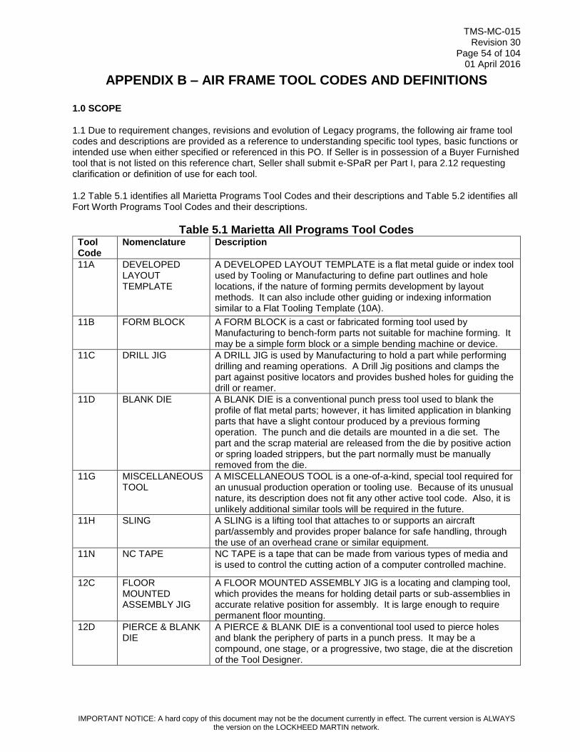
TMS-MC-015 Revision 30
Page 54 of 104 01 April 2016
IMPORTANT NOTICE: A hard copy of this document may not be the document currently in effect. The current version is ALWAYS the version on the LOCKHEED MARTIN network.
APPENDIX B – AIR FRAME TOOL CODES AND DEFINITIONS
1.0 SCOPE 1.1 Due to requirement changes, revisions and evolution of Legacy programs, the following air frame tool codes and descriptions are provided as a reference to understanding specific tool types, basic functions or intended use when either specified or referenced in this PO. If Seller is in possession of a Buyer Furnished tool that is not listed on this reference chart, Seller shall submit e-SPaR per Part I, para 2.12 requesting clarification or definition of use for each tool. 1.2 Table 5.1 identifies all Marietta Programs Tool Codes and their descriptions and Table 5.2 identifies all Fort Worth Programs Tool Codes and their descriptions.
Table 5.1 Marietta All Programs Tool Codes Tool Code
Nomenclature Description
11A DEVELOPED LAYOUT TEMPLATE
A DEVELOPED LAYOUT TEMPLATE is a flat metal guide or index tool used by Tooling or Manufacturing to define part outlines and hole locations, if the nature of forming permits development by layout methods. It can also include other guiding or indexing information similar to a Flat Tooling Template (10A).
11B FORM BLOCK A FORM BLOCK is a cast or fabricated forming tool used by Manufacturing to bench-form parts not suitable for machine forming. It may be a simple form block or a simple bending machine or device.
11C DRILL JIG A DRILL JIG is used by Manufacturing to hold a part while performing drilling and reaming operations. A Drill Jig positions and clamps the part against positive locators and provides bushed holes for guiding the drill or reamer.
11D BLANK DIE A BLANK DIE is a conventional punch press tool used to blank the profile of flat metal parts; however, it has limited application in blanking parts that have a slight contour produced by a previous forming operation. The punch and die details are mounted in a die set. The part and the scrap material are released from the die by positive action or spring loaded strippers, but the part normally must be manually removed from the die.
11G MISCELLANEOUS TOOL
A MISCELLANEOUS TOOL is a one-of-a-kind, special tool required for an unusual production operation or tooling use. Because of its unusual nature, its description does not fit any other active tool code. Also, it is unlikely additional similar tools will be required in the future.
11H SLING A SLING is a lifting tool that attaches to or supports an aircraft part/assembly and provides proper balance for safe handling, through the use of an overhead crane or similar equipment.
11N NC TAPE NC TAPE is a tape that can be made from various types of media and is used to control the cutting action of a computer controlled machine.
12C FLOOR MOUNTED ASSEMBLY JIG
A FLOOR MOUNTED ASSEMBLY JIG is a locating and clamping tool, which provides the means for holding detail parts or sub-assemblies in accurate relative position for assembly. It is large enough to require permanent floor mounting.
12D PIERCE & BLANK DIE
A PIERCE & BLANK DIE is a conventional tool used to pierce holes and blank the periphery of parts in a punch press. It may be a compound, one stage, or a progressive, two stage, die at the discretion of the Tool Designer.

TMS-MC-015 Revision 30
Page 55 of 104 01 April 2016
IMPORTANT NOTICE: A hard copy of this document may not be the document currently in effect. The current version is ALWAYS the version on the LOCKHEED MARTIN network.
Tool Code
Nomenclature Description
12E SAMPLE PART A SAMPLE PART is a Manufacturing or Tooling aid provided as a project tool. It is a dummy of a part or assembly and its configuration varies according to intended use. It is used by Manufacturing to make standard setups on machines and by Tooling to fabricate other tools.
12H SUPPORT FIXTURE
A SUPPORT FIXTURE is a holding tool used by Manufacturing to support an assembly in a position suitable to perform additional work in an out-of-jig position.
13A ABBREVIATED FLAT TEMPLATE
An ABBREVIATED FLAT TEMPLATE is a flat pattern of a portion or portions of a part. The template may include joggles, end detail, trim detail, external cutout detail fabrication lines, production hole patterns, pin holes and tooling holes.
13B HYDRO BLOCK A HYDRO BLOCK is a forming tool used by Manufacturing to form a part by direct application of hydraulic pressure against forming surfaces. The block is in fact a punch upon and around which metallic parts are formed.
13C ASSEMBLY TRIM JIG
An ASSEMBLY TRIM JIG is a profiling guide tool used by Manufacturing to trim a large or complex part or assembly.
13D STEEL RULE DIE A STEEL RULE DIE is a length of spring steel tape used for marking drill holes or locating points across large parts or assemblies. The steel tape contains marks which have been applied in accordance with a tool design, and those marks indicate the points where scribe lines or punch indentations are to be applied.
13E MASTER MODEL A MASTER MODEL is a control tool used by Tooling as a reference master for constructing various project tools. These tools will be constructed from the model within tooling transfer limits. It is a full-scale replica of a contoured portion of an airplane. It is built as close to the Engineering data as is practical and represents the theoretical Engineering data after its completion. The model represents basic criteria which has no tolerance. The model has a reference system (butt lines, station lines, water lines, etc.) and often uses basic lines of sight as the origin of the reference system.
13F RESISTANCE WELD JIG
A RESISTANCE WELD JIG is a locating and clamping tool consisting of a framework with sufficient clamping and locating means to hold two or more parts in accurate relative position and to provide access for spot or resistance welding.
13H DOLLY A DOLLY is rolling equipment used to transport heavy parts, sub-assemblies, assemblies and tools.
14A RADIAL DRILL TEMPLATE
A RADIAL DRILL TEMPLATE is a flat metal guide or index tool used by Tooling or Manufacturing to define part outlines and hole locations, if the nature of forming permits development by layout methods. It can also include other guiding or indexing information, if specified, enabling operations such as piercing, drilling, spot facing, countersinking and dimpling.
14C AUTOMATIC - RIVETING JIG
An AUTOMATIC - RIVETING JIG is an assembly tool used by Manufacturing to position and hold an assembly during an automatic riveting operation. It can be either a portable semi-automatic type (manipulated by hand); or a stationary fully-automatic type (mounted in a fixed position on a machine-controlled bed). The ARJ/14C holds two or more parts in proper relation to each other while an automatic riveting machine punches or drills a hole and inserts and heads a rivet.

TMS-MC-015 Revision 30
Page 56 of 104 01 April 2016
IMPORTANT NOTICE: A hard copy of this document may not be the document currently in effect. The current version is ALWAYS the version on the LOCKHEED MARTIN network.
Tool Code
Nomenclature Description
14D HAMMER DIE A HAMMER DIE is a forming tool used by Manufacturing to form sheet metal parts. It consists of a punch and a die which is mounted in a drop hammer. The punch is usually male, made to the inside of the part, and the die is female, make to the outside of the part.
14E MASTER GAGE A MASTER GAGE is a control tool. It is used by Tool Manufacturing and Tool Inspection to control production tooling for inter-changeable/replaceable end items such as access panels, ailerons, doors, flaps, etc. It is normally a partial replica of the critical mating points (holes, hinge center lines, surfaces, contours, edges) of the item it represents.
14F WELD JIG A WELD JIG is a locating and clamping tool used to hold two or more parts in accurate relative position and provide access for flame or arc welding. It consists of a framework with sufficient clamping and locating means to hold the parts and is made of any suitable material.
15A SET-UP TEMPLATE
A SET-UP TEMPLATE is a flat metal template type tool used by Manufacturing to spot spray rivet locations or to position details on the standard scribe tables for the layout of Chem-Milled parts.
15B FORMED PIN ROUTER BLOCK
A FORMED PIN ROUTER BLOCK is a profiling tool, used on a pin router by Manufacturing. The tool has Guide slots on the underside of the base which controls the movement of part past the router bit as the tool is moved for the cut. The part is guided against a pin on the router table which is in line with the router bit. The tool consists of a base plate, nesting blocks, suitable clamps and tool-handling handles.
15D FORM DIE A FORM DIE, FD/15D, is normally a single operation forming tool used primarily as a bending tool, although drawing or stretching might occur. It may be designed for various forming methods such as punch or hydraulic press, brake press, hydro press, electric discharge, electro-magnetic, etc. The forming action can be by impact or application of controlled pressure.
15E TOOLING MODEL PART
A TOOLING MODEL PART is a tool that is a replica of a part or assembly (which may be abbreviated) used in the tool shop for coordination purposes only.
15H FLOORBOARD A FLOORBOARD is a portable protective covering that is used as a walkway or work platform on or in an aircraft assembly.
16A CHEM-MILL TEMPLATE
A CHEM-MILL TEMPLATE is a tool used as a guide in removing the neoprene or plastic maskant from production parts in the area to be chemically milled.
16B RADIAL-ARM ROUTER BLOCK
A RADIAL-ARM ROUTER BLOCK is a flat guide block used by Manufacturing to profile part blanks. It is used on a standard radial-arm-routing setup, which consists of fastening the block over the material and to the router table; hold-down screws through pin holes within the part or in tabs outside the part are used.
16D DRAW DIE A DRAW DIE is a double-action forming tool and is used by Manufacturing to draw-form sheet metal parts. It consists of a punch made to the inside of part contour, a die made to the outside of part contour, and a draw ring or pressure pad which is spring, air or hydraulically loaded.
16F LOCATING FIXTURE
A LOCATING FIXTURE is an installation tool that indexes to pre-established surfaces and/or holes and provides locating and clamping devices for performing additional assembly operations.
16H HOIST A HOIST is a lifting tool such as a windlass, winch or elevator, and is usually air or electrically powered.

TMS-MC-015 Revision 30
Page 57 of 104 01 April 2016
IMPORTANT NOTICE: A hard copy of this document may not be the document currently in effect. The current version is ALWAYS the version on the LOCKHEED MARTIN network.
Tool Code
Nomenclature Description
17A ANGLE TEMPLATE
An ANGLE TEMPLATE can hold two or more parts in relative position for checking or assembly. It can also serve as a tooling tool to be used in the fabrication of other special tooling.
17B PIN ROUTER BLOCK
A PIN ROUTER BLOCK is a flat guide tool used by Manufacturing to profile flat part blanks on a pin router or shaper. It is made to the net profile of the part blank. The part blank is stacked on top of the block and clamped, using standard router clamps.
17D STRETCH FORM DIE
A STRETCH FORM DIE is a male forming tool used by Manufacturing to form parts by stretching sheet stock, under tension, around the tool profile. The tool, or punch, is made to the inside contour of the part.
17E JIG DRILL PLATE A JIG DRILL PLATE is a guide tool for hand and/or portable power positive feed drilling of hole patterns in sub-assemblies. It may contain features for indexing and for clamping to another tool, or, to a production assembly. It may be a template, flat plate, fiberglass lay-up or a framework, and is made in accordance with best tooling practices.
17F SAW FIXTURE A SAW FIXTURE is a guide tool used to nest and clamp parts or assemblies in a definite relationship to a saw or abrasive cut-off wheel. It is made from any suitable material and is generally
18A APPLY TRIM-&-DRILL TEMPLATE
An APPLY TRIM-&-DRILL TEMPLATE is a flat or formed nesting guide tool. While essentially a guide tool (applied to a part while operations are being performed), it can also be built as an index tool (setting stops or guides of machines or tools).
18B SHAPER BLOCK A SHAPER BLOCK is a guide block used by Manufacturing to profile formed sheet metal or extruded parts on a spindle shaper. The edges of the block guide the profiling cut by moving against a guide collar on the shaper. It has nest blocks, locators, end stops and clamps for locating and securing the part.
18C ASSEMBLY CEMENTING FIXTURE
An ASSEMBLY CEMENTING FIXTURE is a tool that holds two or more product parts in proper relation to each other while they are joined by cementing or adhesives. This tool includes features to locate the parts and details to provide mechanical clamping action when necessary to retain the parts being assembled.
18E CHECK FIXTURE A CHECK FIXTURE is a tool which is used to physically inspect and control formed parts or assemblies within specified dimensions and tolerances. It can be a nest type tool, a base with contour locators, a sheet metal template or any configuration needed to check the part or assembly. It also may include provisions for scribing end of part.
18F MILL FIXTURE A MILL FIXTURE is a locating and clamping tool used to locate a part or parts in a definite relationship to a milling machine table and cutters. It has part locators and clamps, or a clamping device such as a vacuum chuck, and may include cutter set blocks or a touch-off button. Clamps to machine table.
19A APPLY TRIM-&-DRILL TEMPLATE
An APPLY TRIM-&-DRILL TEMPLATE is a flat or formed nesting guide tool. While essentially a guide tool (applied to a part while operations are being performed), it can also be built as an index tool (setting stops or guides of machines or tools).
19B STRETCH FORM BLOCK
A STRETCH FORM BLOCK is a forming tool that may include supporting tooling units such as stretch jaw inserts (set), joggle forming devices, and snakes (flexible filler tool to maintain the shape of certain cross-sections of extrusions or brake formed parts during the forming operation). These blocks are always made to a convex contour and usually to a net contour, but some blocks may require "spring back" allowance incorporated in them.

TMS-MC-015 Revision 30
Page 58 of 104 01 April 2016
IMPORTANT NOTICE: A hard copy of this document may not be the document currently in effect. The current version is ALWAYS the version on the LOCKHEED MARTIN network.
Tool Code
Nomenclature Description
19E MISCELLANEOUS PATTERN EQUIPMENT
A Misc. Pattern Equipment is a pattern fabricated of wood and metal which is use to impress a shape in sand to create the cavity in which to pour molten aluminum.
19F LATHE FIXTURE A LATHE FIXTURE is a centering and clamping tool, used for machining cylindrical or spherical surfaces on a part or parts. These may be internal, external, eccentric or any combination of these. It consists of a base or frame which is adapted to a lathe spindle, lathe chuck, face plate or chuck jaws. It has facilities for locating and gripping the part by nesting and by locators or pins.
19G CUTTING TOOL STANDARD TYPE
A CUTTING TOOL STANDARD TYPE is used by Manufacturing to perform cutting operations which cannot be accomplished by available standard cutters. Normally these tools are made by altering standard tools.
20A HORN ROUTER TEMPLATE
A HORN ROUTER TEMPLATE is a flat or formed nesting guide tool. While essentially a guide tool (applied to a part while operations are being performed), it can also be built as an index tool (setting stops or guides of machines or tools).
20D BLANK DIE - TYPE "D"
A BLANK DIE - TYPE "D" is a profiling tool used by Manufacturing to blank, pierce, slot, trim or any combination of these operations, to produce flat pattern parts. It may consist of (1) cutting or shearing blades and an anvil to equalize and distribute pressure to the cutting blades, or (2) a punch and die with back-up plates and stripping features, used with a standard die set.
20E PLASTER MODEL A PLASTER MODEL is a male or female reference tool used to make other project tools. It is a full-scale model of an airplane part or assembly. It may be modified to allow for shrinkage or draft and shall contain information such as trim lines, beads, traps, etc.
20F GRINDING FIXTURE
A GRINDING FIXTURE is a locating and clamping tool, used for staging a part to a grinding wheel so that a surface can be ground relative to other features of the part. It has various locators and clamps affixed to a base, or it may be a mandrel type fixture for cylindrical grinds on flimsy parts.
20H ACCESS MEANS An ACCESS MEANS is a work stand or platform, ramp, ladder, walkway, or stairway used by Manufacturing to support workers and their tools during the construction or maintenance of an airplane. It is usually built of steel and wood and may contain air and electrical outlets.
21A FORM BLOCK TEMPLATE
A FORM BLOCK TEMPLATE is a flat guide or index tool made to the inside mold line of a formed sheet metal part. It is used by Tooling as a guide in making form blocks or to index jig or check tool details.
21D CUTOFF & PIERCE DIE
A CUTOFF & PIERCE DIE is a conventional punch press tool used to progressively pierce holes in flat strip or coil stock and then cut the part to the desired length.
21E FABRICATED TOOLING PATTERN
FABRICATED TOOLING PATTERN is a wooden, metallic, or composite model suitable for establishing the shape of a fabrication tool detail by making an impression in casting sand, plastic or other casting mediums, or for the fabrication of expandable cauls (MST'S) used in conjunction with lay-up tools for non-metallic parts.
21F BORING FIXTURE A BORING FIXTURE is a locating and holding tool. It has an indicating hole by which the fixture is aligned with the centerline of the machine spindle. The part is located and held by means of locators and clamps affixed to a base, so that the centerline of the hole to be bored is aligned accurately with the spindle of the machine.

TMS-MC-015 Revision 30
Page 59 of 104 01 April 2016
IMPORTANT NOTICE: A hard copy of this document may not be the document currently in effect. The current version is ALWAYS the version on the LOCKHEED MARTIN network.
Tool Code
Nomenclature Description
21H BOX A BOX is a reusable shipping or storage container that is built to hold a particular part or parts. It is usually made from plywood.
22A CONTOUR TEMPLATE
A CONTOUR TEMPLATE is a flat metal male or female index tool whose working edge contacts a specific point on a typical cross section of a curved part or tool. It is used by Manufacturing or Tooling as a checking template to determine conformance of a part to specifications of a curved mold, or heel line, or to establish ends of a part in relation to contour.
22B STRETCH FORM BLOCK
A STRETCH FORM BLOCK is a forming tool that may include supporting tooling units such as stretch jaw inserts (set), joggle forming devices, and snakes (flexible filler tool to maintain the shape of certain cross-sections of extrusions or brake formed parts during the forming operation). These blocks are always made to a convex contour and usually to a net contour, but some blocks may require "spring back" allowance incorporated in them.
22D CUT-OFF DIE A CUT-OFF DIE is a conventional punch press tool used to cut flat strip or coil stock to part length. The die is mounted into a die set. It is a high production, low maintenance tool.
22E PERMANENT MOLD EQUIPMENT
A Permanent Mold Equipment is a mold, usually made of steel, in two pieces that are bolted together to form a cavity into which molten aluminum is poured.
22G FABRICATION TOOL-STANDARD TYPE
A STANDARD-TYPE FABRICATION TOOL is used to fabricate parts to non-standard shapes as required. Not used for machined parts.
23A Box Contour Template
A Box Contour Template consists of a series of individual templates each of which is made to the contour of an engineering part or assembly at a specific station, contour, etc. These templates, when assembled and affixed to a common base, will have a relation which collectively reproduces the contour of the part or assembly.
23D TRIM DIE A TRIM DIE is a conventional-type punch press tool used to trim flat or formed sheet metal parts.
23E BAR DUPLICATING PATTERN
A BAR DUPLICATING PATTERN is a tool which guides the tracer control system of a duplicating machine. It may be composed of one or more sections, according to the length of the part to be machined, and represents the part outline.
23H PROTECTIVE COVER
A PROTECTIVE COVER is a means of covering a specific aircraft part or component to protect it from weather or personnel. The cover can be made of any suitable material.
24A CROSS SECTION TEMPLATE
A CROSS-SECTION TEMPLATE is a flat sheet metal index tool, either male or female, used by Tooling or Manufacturing to check part or tool cross section for conformance to angular and dimensional tolerances.
24D COMBINATION DIE
A COMBINATION DIE is a conventional type punch press tool which combines forming operations with piercing, blanking or trimming. The punch and die units for forming and piercing, blanking or trimming, as well as draw rings and features for releasing the part and scrap material from the die, are all mounted in a common die set.
24E MASTER CONTROL GAGE
MASTER CONTROL GAGE is a tooling tool for the control of critical mating points, holes, surfaces and contours of a Master Gage (MG), or gages, when authorized by Tooling and Manufacturing Technical Directive (TMTD) or Project Tool Engineering Specification (PTES).
24F SPINDLE SHAPER A SPINDLE SHAPER is a custom designed tool, made of common tooling material, used in conjunction with a shaper block to profile formed sheet metal or extruded parts.
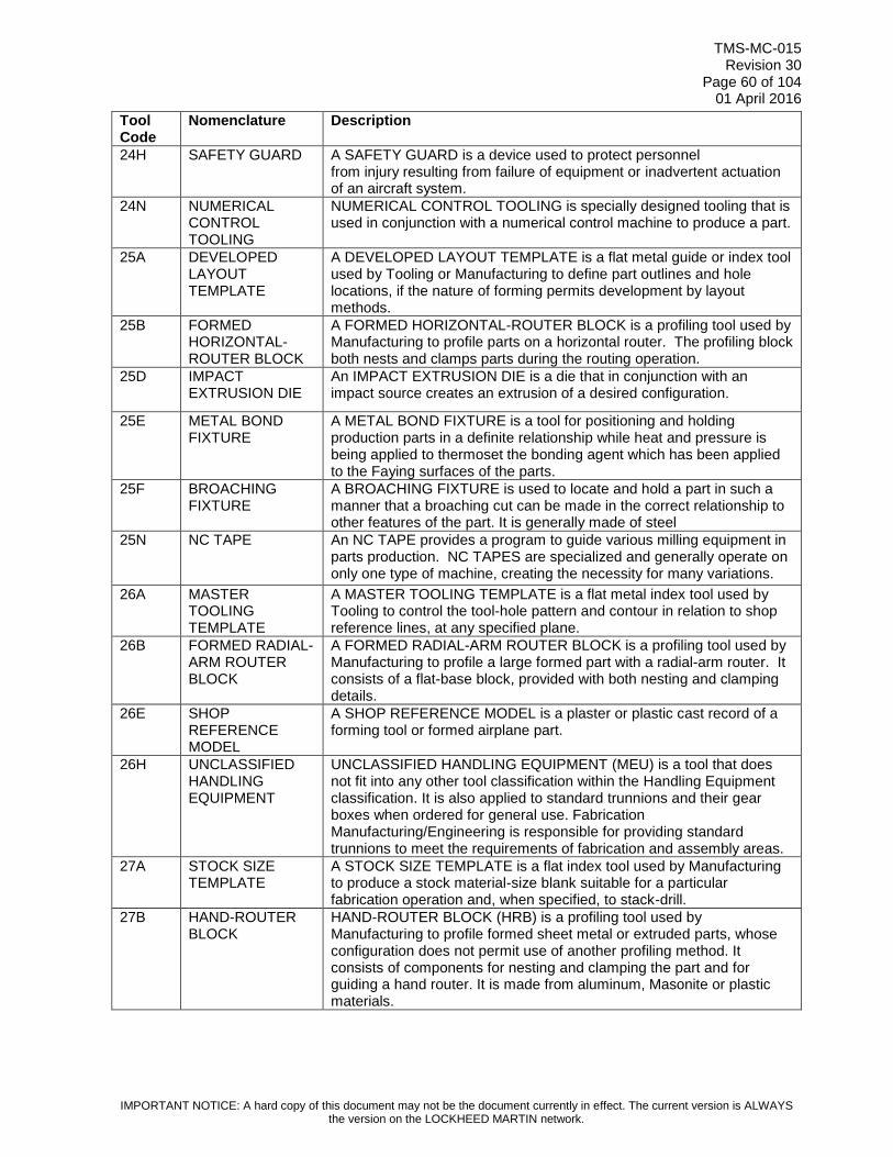
TMS-MC-015 Revision 30
Page 60 of 104 01 April 2016
IMPORTANT NOTICE: A hard copy of this document may not be the document currently in effect. The current version is ALWAYS the version on the LOCKHEED MARTIN network.
Tool Code
Nomenclature Description
24H SAFETY GUARD A SAFETY GUARD is a device used to protect personnel from injury resulting from failure of equipment or inadvertent actuation of an aircraft system.
24N NUMERICAL CONTROL TOOLING
NUMERICAL CONTROL TOOLING is specially designed tooling that is used in conjunction with a numerical control machine to produce a part.
25A DEVELOPED LAYOUT TEMPLATE
A DEVELOPED LAYOUT TEMPLATE is a flat metal guide or index tool used by Tooling or Manufacturing to define part outlines and hole locations, if the nature of forming permits development by layout methods.
25B FORMED HORIZONTAL-ROUTER BLOCK
A FORMED HORIZONTAL-ROUTER BLOCK is a profiling tool used by Manufacturing to profile parts on a horizontal router. The profiling block both nests and clamps parts during the routing operation.
25D IMPACT EXTRUSION DIE
An IMPACT EXTRUSION DIE is a die that in conjunction with an impact source creates an extrusion of a desired configuration.
25E METAL BOND FIXTURE
A METAL BOND FIXTURE is a tool for positioning and holding production parts in a definite relationship while heat and pressure is being applied to thermoset the bonding agent which has been applied to the Faying surfaces of the parts.
25F BROACHING FIXTURE
A BROACHING FIXTURE is used to locate and hold a part in such a manner that a broaching cut can be made in the correct relationship to other features of the part. It is generally made of steel
25N NC TAPE An NC TAPE provides a program to guide various milling equipment in parts production. NC TAPES are specialized and generally operate on only one type of machine, creating the necessity for many variations.
26A MASTER TOOLING TEMPLATE
A MASTER TOOLING TEMPLATE is a flat metal index tool used by Tooling to control the tool-hole pattern and contour in relation to shop reference lines, at any specified plane.
26B FORMED RADIAL-ARM ROUTER BLOCK
A FORMED RADIAL-ARM ROUTER BLOCK is a profiling tool used by Manufacturing to profile a large formed part with a radial-arm router. It consists of a flat-base block, provided with both nesting and clamping details.
26E SHOP REFERENCE MODEL
A SHOP REFERENCE MODEL is a plaster or plastic cast record of a forming tool or formed airplane part.
26H UNCLASSIFIED HANDLING EQUIPMENT
UNCLASSIFIED HANDLING EQUIPMENT (MEU) is a tool that does not fit into any other tool classification within the Handling Equipment classification. It is also applied to standard trunnions and their gear boxes when ordered for general use. Fabrication Manufacturing/Engineering is responsible for providing standard trunnions to meet the requirements of fabrication and assembly areas.
27A STOCK SIZE TEMPLATE
A STOCK SIZE TEMPLATE is a flat index tool used by Manufacturing to produce a stock material-size blank suitable for a particular fabrication operation and, when specified, to stack-drill.
27B HAND-ROUTER BLOCK
HAND-ROUTER BLOCK (HRB) is a profiling tool used by Manufacturing to profile formed sheet metal or extruded parts, whose configuration does not permit use of another profiling method. It consists of components for nesting and clamping the part and for guiding a hand router. It is made from aluminum, Masonite or plastic materials.

TMS-MC-015 Revision 30
Page 61 of 104 01 April 2016
IMPORTANT NOTICE: A hard copy of this document may not be the document currently in effect. The current version is ALWAYS the version on the LOCKHEED MARTIN network.
Tool Code
Nomenclature Description
27D COMBINATION DIE
A COMBINATION DIE is a conventional type punch press tool which combines forming operations with piercing, blanking or trimming. The punch and die units for forming and piercing, blanking or trimming, as well as draw rings and features for releasing of the part and scrap material from the die, are all mounted in a common die set.
27F TEST FIXTURE The TEST FIXTURE is a tool used to hold a production part during the application of a test load.
28B HAND-ROUTER BLOCK
A HAND-ROUTER BLOCK is a profiling tool used by Manufacturing to profile formed sheet metal or extruded parts, whose configuration does not permit use of another profiling method. It consists of components for nesting and clamping the part and for guiding a hand router.
28D EXPLOSIVE FORM DIE
An EXPLOSIVE FORM DIE is primarily used to produce sheet metal product parts such as domes, hemispheres, conical shapes, beaded or sculptured panels and for bulge forming tubular metal parts. A secondary function of this tool is its use as a preform die or sizing die.
28E BAR DUPLICATING PATTERN
A BAR DUPLICATING PATTERN is a tool which guides the tracer control system of a duplicating machine. It may be composed of one or more sections, according to the length of the part to be machined, and represents the part outline.
29F Transporting Fixture
A Transporting Fixture is a tool used to move large sections of the aircraft prior to installation of the landing gear and wheels.
30D MOLD DIE PLASTIC CERAMIC
A MOLD DIE-PLASTIC/CERAMIC is a forming tool used on a low-pressure, electrically heated-platen press for molding plastic or resin parts
30E FACILITY GAGE A FACILITY GAGE is a control tool. It is used to control production tooling for critical manufacturing joints/interfaces and receiving structure features common to interchangeability and replaceability (I & R) end items such as access panels, ailerons, doors, flaps, etc.
31F FORMING FIXTURE
A FORMING FIXTURE is a tool for forming (or preforming) a production part.
32F WELD JIG A WELD JIG is a locating and clamping tool used to hold two or more parts in accurate relative position and provide access for flame or arc welding.
33A MASTER TOOLING TEMPLATE
A MASTER TOOLING TEMPLATE is a flat metal index tool used by Tooling to control the tool-hole pattern and contour in relation to shop order reference lines.
33F HEAT TREAT FIXTURE
A HEAT TREAT FIXTURE is a tool used to hold an engineering part or assembly during heat-treating operations. The fixture prevents warpage or distortion due to stresses set up by the temperature changes encountered in heat-treating processes. It has sufficient clamping means to hold the part in accurate position while being annealed, stress relieved, normalized or hardened.
34F FIXTURE ATTACHING BASE
A FIXTURE ATTACHING BASE is an accessory tool used only as an intermediate base between a prime tool(s) and a machine.
34G QUALITY CONTROL GAGE
A QUALITY CONTROL GAGE is a custom gage made of common tooling material for the use of quality control personnel to verify critical dimension(s) of a specific part.
34H MISCELLANEOUS DEVICE - FUNCTIONAL TEST
A MISCELLANEOUS DEVICE - FUNCTIONAL TEST is a rack, cart, shelf, handle or restraint created to secure associated equipment during the functional testing of hydraulic or electrical components.

TMS-MC-015 Revision 30
Page 62 of 104 01 April 2016
IMPORTANT NOTICE: A hard copy of this document may not be the document currently in effect. The current version is ALWAYS the version on the LOCKHEED MARTIN network.
Tool Code
Nomenclature Description
35A TOOLING MASTER LAYOUT
Soft tooling – (TLMO) is a full scale layout of a part or assembly. It is used by Tooling as a photographic master to show Tooling or Manufacturing details needed to supplement Engineering requirements. From the photographic master, dimensional control data can be determined or reproductions for tool shop use can be produced. It is made on dimensionally stable material (Mylar film), according to Engineering or Tooling Information.
37A HEAT TREAT FIXTURE
A HEAT TREAT FIXTURE is a tool used to hold an engineering part or assembly during heat-treating operations. The fixture prevents warpage or distortion due to stresses set up by the temperature changes encountered in heat-treating processes. It has sufficient clamping means to hold the part in accurate position while being annealed, stress relieved, normalized or hardened.
40C ASSEMBLY JIG An ASSEMBLY JIG is a locating and clamping tool, providing the means for holding two or more parts in accurate relative position for assembly. It is a portable tool, small enough to be stored in a tool crib. It is made from any suitable tooling material.
41B SPIN BLOCK A SPIN BLOCK is a forming tool for concentric parts whose size, shape and configuration are adaptable to this method of forming. It is used by Manufacturing on a spinning lathe for forming and trimming operations and also may be used for a pre-form operation prior to die forming in order to minimize stretch or thinning.
41E LAY-UP BLOCK A LAY-UP BLOCK is a male or female molding tool used by Manufacturing to fabricate reinforced laminated plastic parts. It has a working surface which represents the inside or outside of a plastic part.
42C Floor Mounted Riveting Jig
A FLOOR MOUNTED RIVETING JIG is a holding and clamping tool used by Manufacturing to prevent important attach points and contours on the production assembly from moving and distorting while being drilled and riveted. It is floor mounted in a specific location because of the size and complexity of the production assembly. It is made from any suitable tooling material.
42E MOLDING DIE A MOLDING DIE is a forming tool consisting of a male punch and a female die. The punch is made to inside part contour and the die is made to outside part contour. It has alignment pins to align the punch and die and depth stops to control part thickness.
43A DEVELOPED BLANK TEMPLATE
A DEVELOPED BLANK TEMPLATE is a flat pattern development to enable Manufacturing to produce blanks suitable for forming operations. The development includes material allowances as required to compensate for the shrinking, stretching, or flowing of material during the forming operation.
43D JOGGLE DIE A JOGGLE DIE is a single action forming tool used to offset any portion of a part. It consists of a punch and die which may be solid or in several pieces, with separations at the bend lines of the part.
43E MOLDING DIE A MOLDING DIE is a forming tool consisting of a male punch and a female die. The punch is made to inside part contour and the die is made to outside part contour. It has alignment pins to align the punch and die and depth stops to control part thickness.
44E METAL BOND FIXTURE
A METAL BOND FIXTURE is a tool for positioning and holding production parts in a definite relationship while heat and pressure is being applied to thermoset the bonding agent which has been applied to the Faying surfaces of the parts.
46E THERMO-PLASTIC FORM BLOCK
A THERMO-PLASTIC FORM BLOCK is a forming tool, used with a transit-topped heat table, which holds and forms thermo-setting plastic materials after the localized application of heat.
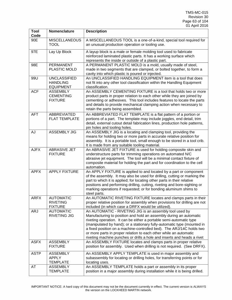
TMS-MC-015 Revision 30
Page 63 of 104 01 April 2016
IMPORTANT NOTICE: A hard copy of this document may not be the document currently in effect. The current version is ALWAYS the version on the LOCKHEED MARTIN network.
Tool Code
Nomenclature Description
90E MISCELLANEOUS TOOL
A MISCELLANEOUS TOOL is a one-of-a-kind, special tool required for an unusual production operation or tooling use.
97E Lay Up Block A layup block is a male or female molding tool used to fabricate reinforced laminated plastic parts. It has a working surface which represents the inside or outside of a plastic part.
98E PERMANENT PLASTIC MOLD
A PERMANENT PLASTIC MOLD is a mold, usually made of steel, made in two segments that are clamped, or bolted together, to form a cavity into which plastic is poured or injected.
99U UNCLASSIFIED HANDLING EQUIPMENT
An UNCLASSIFIED HANDLING EQUIPMENT item is a tool that does not fit into any other tool classification within the Handling Equipment classification.
ACF ASSEMBLY CEMENTING FIXTURE
An ASSEMBLY CEMENTING FIXTURE is a tool that holds two or more product parts in proper relation to each other while they are joined by cementing or adhesives. This tool includes features to locate the parts and details to provide mechanical clamping action when necessary to retain the parts being assembled.
AFT ABBREVIATED FLAT TEMPLATE
An ABBREVIATED FLAT TEMPLATE is a flat pattern of a portion or portions of a part. The template may include joggles, end detail, trim detail, external cutout detail fabrication lines, production hole patterns, pin holes and tooling holes.
AJ ASSEMBLY JIG An ASSEMBLY JIG is a locating and clamping tool, providing the means for holding two or more parts in accurate relative position for assembly. It is a portable tool, small enough to be stored in a tool crib. It is made from any suitable tooling material.
AJFX ABRASIVE JET FIXTURE
An ABRASIVE JET FIXTURE is used for holding composite skin and understructure parts for trimming operations on automated N/C abrasive jet equipment. The tool will be a minimal contact fixture of composite material for holding the part and for coordination to the cell automation.
APFX APPLY FIXTURE An APPLY FIXTURE is applied to and located by a part or component of the assembly. It may also be used for drilling, cutting or marking the part to which it is applied; for locating other parts in their relative positions and performing drilling, cutting, riveting and bore-sighting or marking operations if requested; or for bonding aluminum shims to steel parts.
ARFX AUTOMATIC RIVETING FIXTURE
An AUTOMATIC RIVETING FIXTURE locates and clamps parts in their proper relative position for assembly when provisions for drilling are not included (in which case a DRFX would be utilized).
ARJ AUTOMATIC RIVETING JIG
An AUTOMATIC - RIVETING JIG is an assembly tool used by Manufacturing to position and hold an assembly during an automatic riveting operation. It can be either a portable semi-automatic type (manipulated by hand); or a stationary fully-automatic type (mounted in a fixed position on a machine-controlled bed). The ARJ/14C holds two or more parts in proper relation to each other while an automatic riveting machine punches or drills a hole and inserts and heads a rivet
ASFX ASSEMBLY FIXTURE
An ASSEMBLY FIXTURE locates and clamps parts in proper relative position for assembly. Used when drilling is not required. (See DRFX).
ASTP ASSEMBLY APPLY TEMPLATE
An ASSEMBLY APPLY TEMPLATE is used in major assembly and subassembly for locating or drilling holes, for transferring points or for locating uses.
AT ASSEMBLY TEMPLATE
An ASSEMBLY TEMPLATE holds a part or assembly in its proper position in a major assembly during installation while it is being drilled.
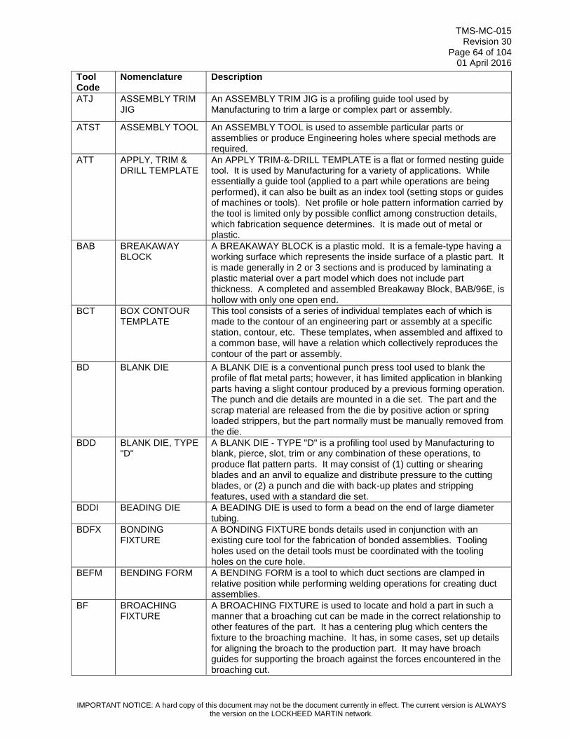
TMS-MC-015 Revision 30
Page 64 of 104 01 April 2016
IMPORTANT NOTICE: A hard copy of this document may not be the document currently in effect. The current version is ALWAYS the version on the LOCKHEED MARTIN network.
Tool Code
Nomenclature Description
ATJ ASSEMBLY TRIM JIG
An ASSEMBLY TRIM JIG is a profiling guide tool used by Manufacturing to trim a large or complex part or assembly.
ATST ASSEMBLY TOOL An ASSEMBLY TOOL is used to assemble particular parts or assemblies or produce Engineering holes where special methods are required.
ATT APPLY, TRIM & DRILL TEMPLATE
An APPLY TRIM-&-DRILL TEMPLATE is a flat or formed nesting guide tool. It is used by Manufacturing for a variety of applications. While essentially a guide tool (applied to a part while operations are being performed), it can also be built as an index tool (setting stops or guides of machines or tools). Net profile or hole pattern information carried by the tool is limited only by possible conflict among construction details, which fabrication sequence determines. It is made out of metal or plastic.
BAB BREAKAWAY BLOCK
A BREAKAWAY BLOCK is a plastic mold. It is a female-type having a working surface which represents the inside surface of a plastic part. It is made generally in 2 or 3 sections and is produced by laminating a plastic material over a part model which does not include part thickness. A completed and assembled Breakaway Block, BAB/96E, is hollow with only one open end.
BCT BOX CONTOUR TEMPLATE
This tool consists of a series of individual templates each of which is made to the contour of an engineering part or assembly at a specific station, contour, etc. These templates, when assembled and affixed to a common base, will have a relation which collectively reproduces the contour of the part or assembly.
BD BLANK DIE A BLANK DIE is a conventional punch press tool used to blank the profile of flat metal parts; however, it has limited application in blanking parts having a slight contour produced by a previous forming operation. The punch and die details are mounted in a die set. The part and the scrap material are released from the die by positive action or spring loaded strippers, but the part normally must be manually removed from the die.
BDD BLANK DIE, TYPE "D"
A BLANK DIE - TYPE "D" is a profiling tool used by Manufacturing to blank, pierce, slot, trim or any combination of these operations, to produce flat pattern parts. It may consist of (1) cutting or shearing blades and an anvil to equalize and distribute pressure to the cutting blades, or (2) a punch and die with back-up plates and stripping features, used with a standard die set.
BDDI BEADING DIE A BEADING DIE is used to form a bead on the end of large diameter tubing.
BDFX BONDING FIXTURE
A BONDING FIXTURE bonds details used in conjunction with an existing cure tool for the fabrication of bonded assemblies. Tooling holes used on the detail tools must be coordinated with the tooling holes on the cure hole.
BEFM BENDING FORM A BENDING FORM is a tool to which duct sections are clamped in relative position while performing welding operations for creating duct assemblies.
BF BROACHING FIXTURE
A BROACHING FIXTURE is used to locate and hold a part in such a manner that a broaching cut can be made in the correct relationship to other features of the part. It has a centering plug which centers the fixture to the broaching machine. It has, in some cases, set up details for aligning the broach to the production part. It may have broach guides for supporting the broach against the forces encountered in the broaching cut.

TMS-MC-015 Revision 30
Page 65 of 104 01 April 2016
IMPORTANT NOTICE: A hard copy of this document may not be the document currently in effect. The current version is ALWAYS the version on the LOCKHEED MARTIN network.
Tool Code
Nomenclature Description
BOF BORING FIXTURE A BORING FIXTURE is a locating and holding tool. It has an indicating hole by which the fixture is aligned with the centerline of the machine spindle. The part is located and held by means of locators and clamps affixed to a base, so that the centerline of the hole to be bored is aligned accurately with the spindle of the machine.
BORF BORING FIXTURE A BORING FIXTURE is a locating and holding tool. It has an indicating hole by which the fixture is aligned with the centerline of the machine spindle. The part is located and held by means of locators and clamps affixed to a base, so that the centerline of the hole to be bored is aligned accurately with the spindle of the machine.
BUP BACK-UP PLATE A BACK-UP PLATE is used in lieu of a fixture for machining production components. It serves as a spacer between the bed of the machine tool and the component being machined, establishing the component at a definite distance from the machine bed. This established distance lessens the possibility of the cutter being run into the machine tool.
CD COMBINATION DIE
A COMBINATION DIE is a conventional type punch press tool which combines forming operations with piercing, blanking or trimming. The punch and die units for forming and piercing, blanking or trimming, as well as draw rings and features for releasing the part and scrap material from the die, are all mounted in a common die set.
CDTO COMPOSITE DEBULK TOOL
A COMPOSITE DEBULK TOOL is used for the layup and cold debulk of an understructure detail part prior to loading it into a curing tool. The tool consists of multiple NC-machined details with a base plate.
CF CHECK FIXTURE A CHECK FIXTURE is a tool which is used to physically inspect and control formed parts or assemblies within specified dimensions and tolerances. It can be a nest type tool, a base with contour locators, a sheet metal template or any configuration needed to check the part or assembly. It also may include provisions for scribing end of part.
CKG CHECK GAGE A CHECK GAGE is a tool which verifies inside dimensions, outside dimensions, lengths, weights or volumes during the production or inspection of production parts or project or standard tools.
CKGA CHECK GAGE A CHECK GAGE is a tool which verifies inside dimensions, outside dimensions, lengths, weights or volumes during the production or inspection of production parts or project or standard tools.
CKTP CHECK TEMPLATE
A CHECK TEMPLATE is a flat pattern used to compare or check contours or angles. This template can be used to check a tool or to compare production parts.
CMDU Color Multi-Function Display Unit
A personal computer (PC) based piece of special test equipment (STE) used to perform acceptance testing, diagnostics, and reprogramming of CMDU, a cockpit display.
CMF COMPOSITE MOLD FIXTURE
A COMPOSITE MOLDING FIXTURE is a forming tool used for molding resin impregnated and pre impregnated composite parts. It generally is an open mold with pressure control in an autoclave. The tool consists of metal and/or rubber forming mandrels, metal or graphite base and cover plates, or bonding fixtures with conventional bagging or envelop bagging. The tool sometimes utilizes air pad overlays for precise pressure control.
COFX COMPONENT FIXTURE
A COFX is used to hold, position, and/or transport the whole component after structural assembly is complete. A Tool Design drawing is required. The tool indexes to and maintains dimensional control of previously established points that are essential in order to control the accuracy of the components.
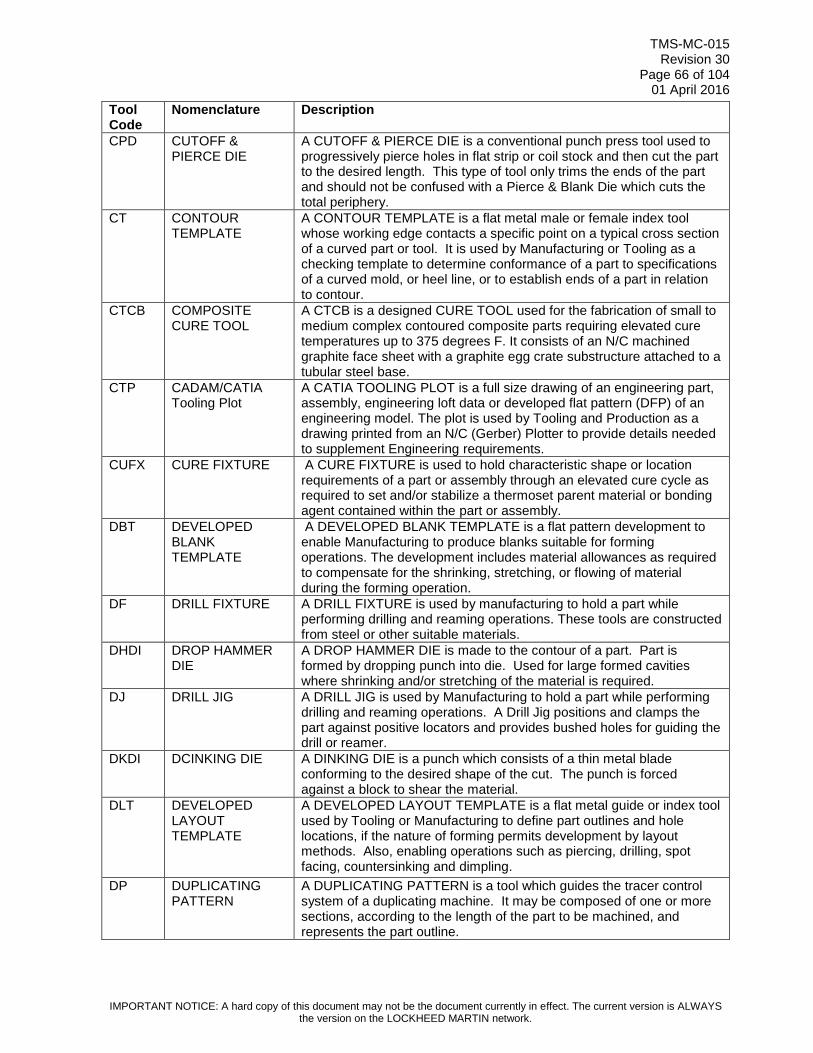
TMS-MC-015 Revision 30
Page 66 of 104 01 April 2016
IMPORTANT NOTICE: A hard copy of this document may not be the document currently in effect. The current version is ALWAYS the version on the LOCKHEED MARTIN network.
Tool Code
Nomenclature Description
CPD CUTOFF & PIERCE DIE
A CUTOFF & PIERCE DIE is a conventional punch press tool used to progressively pierce holes in flat strip or coil stock and then cut the part to the desired length. This type of tool only trims the ends of the part and should not be confused with a Pierce & Blank Die which cuts the total periphery.
CT CONTOUR TEMPLATE
A CONTOUR TEMPLATE is a flat metal male or female index tool whose working edge contacts a specific point on a typical cross section of a curved part or tool. It is used by Manufacturing or Tooling as a checking template to determine conformance of a part to specifications of a curved mold, or heel line, or to establish ends of a part in relation to contour.
CTCB COMPOSITE CURE TOOL
A CTCB is a designed CURE TOOL used for the fabrication of small to medium complex contoured composite parts requiring elevated cure temperatures up to 375 degrees F. It consists of an N/C machined graphite face sheet with a graphite egg crate substructure attached to a tubular steel base.
CTP CADAM/CATIA Tooling Plot
A CATIA TOOLING PLOT is a full size drawing of an engineering part, assembly, engineering loft data or developed flat pattern (DFP) of an engineering model. The plot is used by Tooling and Production as a drawing printed from an N/C (Gerber) Plotter to provide details needed to supplement Engineering requirements.
CUFX CURE FIXTURE A CURE FIXTURE is used to hold characteristic shape or location requirements of a part or assembly through an elevated cure cycle as required to set and/or stabilize a thermoset parent material or bonding agent contained within the part or assembly.
DBT DEVELOPED BLANK TEMPLATE
A DEVELOPED BLANK TEMPLATE is a flat pattern development to enable Manufacturing to produce blanks suitable for forming operations. The development includes material allowances as required to compensate for the shrinking, stretching, or flowing of material during the forming operation.
DF DRILL FIXTURE A DRILL FIXTURE is used by manufacturing to hold a part while performing drilling and reaming operations. These tools are constructed from steel or other suitable materials.
DHDI DROP HAMMER DIE
A DROP HAMMER DIE is made to the contour of a part. Part is formed by dropping punch into die. Used for large formed cavities where shrinking and/or stretching of the material is required.
DJ DRILL JIG A DRILL JIG is used by Manufacturing to hold a part while performing drilling and reaming operations. A Drill Jig positions and clamps the part against positive locators and provides bushed holes for guiding the drill or reamer.
DKDI DCINKING DIE A DINKING DIE is a punch which consists of a thin metal blade conforming to the desired shape of the cut. The punch is forced against a block to shear the material.
DLT DEVELOPED LAYOUT TEMPLATE
A DEVELOPED LAYOUT TEMPLATE is a flat metal guide or index tool used by Tooling or Manufacturing to define part outlines and hole locations, if the nature of forming permits development by layout methods. Also, enabling operations such as piercing, drilling, spot facing, countersinking and dimpling.
DP DUPLICATING PATTERN
A DUPLICATING PATTERN is a tool which guides the tracer control system of a duplicating machine. It may be composed of one or more sections, according to the length of the part to be machined, and represents the part outline.

TMS-MC-015 Revision 30
Page 67 of 104 01 April 2016
IMPORTANT NOTICE: A hard copy of this document may not be the document currently in effect. The current version is ALWAYS the version on the LOCKHEED MARTIN network.
Tool Code
Nomenclature Description
DPDI DYNAPAK DIE A DYNAPAK DIE is a punch and die used for producing a close tolerance forging from a billet or bar with DYNAPAK equipment. It may also forcibly extrude material through an aperture with a punch.
DRD DRAW DIE A DRAW DIE is a double-action forming tool and is used by Manufacturing to draw-form sheet metal parts. It consists of a punch made to the inside of part contour, a die made to the outside of part contour, and a draw ring or pressure pad which is spring, air or hydraulically loaded.
DRFX DRILL FIXTURE A DRILL FIXTURE is a tool in which parts are located and clamped for assembly with the location of holes determined by the position of bushings or plates.
DRJI DRILL JIG A DRILL JIG is a tool in which a part is located and clamped while drilling, reaming, counter boring, countersinking or similar operations are performed. The tool is provided with hardened bushings or other means for guiding the cutting tools.
DRLJ DRILL JIG A DRILL JIG is used by manufacturing to hold a part while performing drilling and reaming operations. A DRILL JIG positions and clamps the part against positive locators and provides bushed holes for guiding the drill bit or reamer.
DRPE DRILL PLATE A DRILL PLATE is a flat piece of material provided with bushings or adapter size holes, used for drilling and/or reaming a hole or a pattern of holes in part. Tool is indexed to the part by means of pins or by using the edges of the plate for alignment.
DUPA DUPLICATING PATTERN
A DUPLICATING PATTERN is a cam of variable width or irregular shape used to control the direction of travel and/or depth of cutting tool in machining a surface and/or perimeter of a part.
DWDI DRAW DIE A DRAW DIE is a tool in which the punch is to the desired inside shape of a part and the die section is to outside shape with proper clearance. The material is held by pressure pads and the punch draws the material into the die.
DWFM DRAW FORM A DRAW FORM is a punch and draw die ring used in forming a part on Hi-Draw machines.
ENMO ENCAPSULATION MOLD
An ENCAPSULATION MOLD is a permanent type mold used to surround a part during casting.
FAB FIXTURE ATTACHING BASE
A FIXTURE ATTACHING BASE is an accessory tool used only as an intermediate base between a prime tool(s) and a machine.
FAJ FLOOR-MOUNTED ASSEMBLY JIG
A FLOOR MOUNTED ASSEMBLY JIG is a locating and clamping tool, which provides the means for holding detail parts or sub-assemblies in accurate relative position for assembly.
FB FORM BLOCK A FORM BLOCK is a cast or fabricated forming tool used by Manufacturing to bench-form parts not suitable for machine forming. It may be a simple form block or a simple bending machine or device.
FBT FORM BLOCK TEMPLATE
A FORM BLOCK TEMPLATE is a flat guide or index tool made to the inside mold line of a formed sheet metal part. It is used by Tooling as a guide in making form blocks or to index jig or check tool details.
FD FORM DIE A FORM DIE, FD, is normally a single operation forming tool used primarily as a bending tool, although drawing or stretching might occur. It may be designed for various forming methods such as punch or hydraulic press, brake press, hydro press, electric discharge, electro-magnetic, etc. The forming action can be by impact or application of controlled pressure.

TMS-MC-015 Revision 30
Page 68 of 104 01 April 2016
IMPORTANT NOTICE: A hard copy of this document may not be the document currently in effect. The current version is ALWAYS the version on the LOCKHEED MARTIN network.
Tool Code
Nomenclature Description
FFD FLUID FORMING DIE
A FLUID FORMING DIE is a metal-forming tool which utilizes hydraulic pressure to replace a conventionally-shaped punch.
FG FACILITY GAGE A FACILITY GAGE is a control tool. It is used to control production tooling for critical manufacturing joints/interfaces and receiving structure features common to interchangeability and replaceability (I & R) end items such as access panels, ailerons, doors, flaps, etc. Also, it may be used as an optical tooling aid to control features relative to tar-gets/lines of sight.
FGD FORGING DIE A FORGING DIE provides a rough cavity for forging aluminum or steel castings. Castings which have been forged are then machined as required to provide critical surfaces.
FLTP FLAT TOOLING TEMPLATE
A FLAT TOOLING TEMPLATE is a flat metal guide or index tool used by tooling or manufacturing to define part outlines and hole locations, if the nature of forming permits development by layout methods. It can also include other guiding or indexing information if specified, enabling operations such as piercing, drilling, spot facing, countersinking and dimpling.
FMM FORM MALE MOLD
FORM MALE MOLD is a master tool.
FMTO FORM TOOL A FORM TOOL can be (1) a piece of steel or other hard material having a cutting edge shaped to the form desired on a finished turned part, or (2) a tool which forms by exerting pressure on one relatively small section of the part at a time.
FPML Fiber Placement Mandrel
FIBER PLACEMENT MANDREL - A segmented tool that provides interface to the fiber placement machinery for the automated tow placement process and elevated temperature cure.
FPRB FORMED PIN-ROUTER BLOCK
A FORMED PIN ROUTER BLOCK is a profiling tool, used on a pin router by Manufacturing. The tool has build slots on the underside of the base which controls the movement of part past the router bit as the tool is moved for the cut. The part is guided against a pin on the router table which is in line with the router bit.
FRJ FLOOR-MOUNTED RIVETING JIG
A FLOOR MOUNTED RIVETING JIG is a holding and clamping tool used by Manufacturing to prevent important attach points and contours on the production assembly from moving and distorting while being drilled and riveted.
FRMD FORM DIE A FORM DIE is normally a single operation forming tool used primarily as a bending tool, although drawing or stretching might occur. It may be designed for various forming methods such as punch or hydraulic press, brake press, hydra press, electric discharge, electro-magnetic, etc. The forming action can be by impact or application of controlled pressure.
FRRB FORMED RADIAL ARM ROUTER BLOCK
A FORMED RADIAL-ARM ROUTER BLOCK is a profiling tool used by Manufacturing to profile a large formed part with a radial-arm router. It consists of a flat-base block, provided with both nesting and clamping details.
FTP FABRICATED TOOLING PATTERN
A FABRICATED TOOLING PATTERN is a wooden, metallic, or composite model suitable for establishing the shape of a fabrication tool detail by making an impression in casting sand, plastic or other casting mediums.
GF GRINDING FIXTURE
A GRINDING FIXTURE is a locating and clamping tool, used for staging a part to a grinding wheel so that a surface can be ground relative to other features of the part.

TMS-MC-015 Revision 30
Page 69 of 104 01 April 2016
IMPORTANT NOTICE: A hard copy of this document may not be the document currently in effect. The current version is ALWAYS the version on the LOCKHEED MARTIN network.
Tool Code
Nomenclature Description
HB HYDRO BLOCK A HYDRO BLOCK is a forming tool used by Manufacturing to form a part by direct application of hydraulic pressure against forming surfaces.
HD HAMMER DIE A HAMMER DIE is a forming tool used by Manufacturing to form sheet metal parts. It consists of a punch and a die which is mounted in a drop hammer.
HDP HYDROFORM PATTERN
A HYDROFORM PATTERN is utilized in forming and/or modeling plastic parts. Usually made of plaster.
HF HOLDING FIXTURE
A HOLDING FIXTURE captures and aligns a production part during machining, welding or drilling operations.
HRB HAND ROUTER BLOCK
A HAND-ROUTER BLOCK is a profiling tool used by Manufacturing to profile formed sheet metal or extruded parts, whose configuration does not permit use of another profiling method.
HRT HORN ROUTER TEMPLATE
A HORN ROUTER TEMPLATE is a flat of formed nesting guide tool. While essentially a guide tool (applied to a part while operations are being performed), it can also be built as an index tool (setting stops or guides of machines or tools.
HTF HEAT TREAT FIXTURE
A HEAT TREAT FIXTURE is a tool used to hold an engineering part or assembly during heat treating operations. The fixture prevents warpage or distortion due to stresses set up by the temperature changes encountered in heat treating processes. It has sufficient clamping means to hold the part in accurate position while being annealed, stress relieved, normalized or hardened. It is made from metal or ceramics.
IJMO INJECTION MOLD An INJECTION MOLD is a closed-cavity matched die mold into which material is injected under pressure from an outside source.
INFX Inspection Fixture INSPECTION FIXTURE - A check fixture for castings and forgings.
INGA Inspection Gauge INSPECTION GAGE - A tool used for checking parts. A Tool Design drawing is required.
INSJ INSPECTION FIXTURE
An INSPECTION FIXTURE is a tool which is used to physically inspect and control formed part or assemblies within specified dimensions and tolerances. It can be a nest type of tool, a base with contour locators, a sheet metal template or any configuration needed to check the part or assembly. It also may include provisions for scribing end of the part.
JDP TEJIG DRILL PLA A JIG DRILL PLATE is a guide tool for hand and/or portable power positive feed drilling of hole patterns in sub-assemblies.
LAF LATHE FIXTURE A LATHE FIXTURE is a centering and clamping tool, used for machining cylindrical or spherical surfaces on a part or parts.
LATP LAMINATE TEMPLATE
A LAMINATE TEMPLATE is a template or set of templates made of stable translucent material and used to control laminate fiber direction, perimeter (with excess as required) and indexing provisions to relate the laminates to each other and to common reference points.
LF LOCATING FIXTURE
A LOCATING FIXTURE is an installation tool that indexes to pre-established surfaces and/or holes and provides locating and clamping devices for performing additional assembly operations.
LTHF/LATF
LATHE FIXTURE A LATHE FIXTURE is a centering and clamping tool, used for machining cylindrical or spherical surfaces on a part or parts.
LUB LAYUP BLOCK A LAY-UP BLOCK is a male or female molding tool used by Manufacturing to fabricate reinforced laminated plastic parts. It has a working surface which represents the inside or outside of a plastic part.
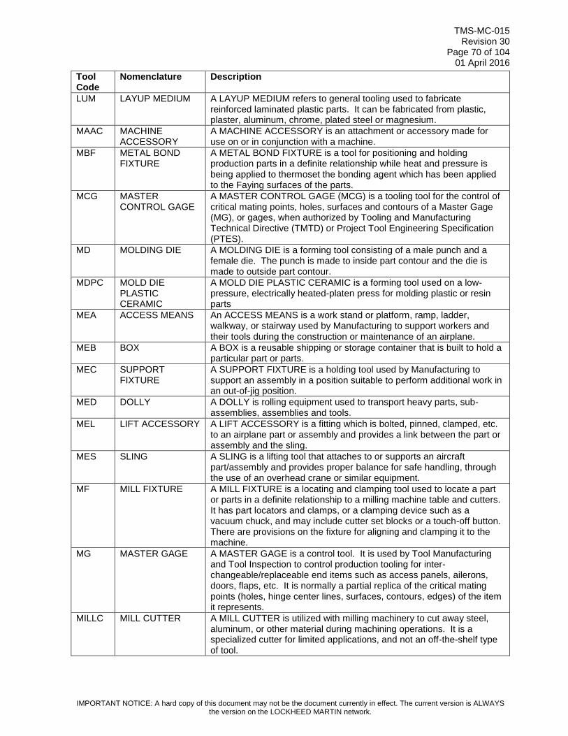
TMS-MC-015 Revision 30
Page 70 of 104 01 April 2016
IMPORTANT NOTICE: A hard copy of this document may not be the document currently in effect. The current version is ALWAYS the version on the LOCKHEED MARTIN network.
Tool Code
Nomenclature Description
LUM LAYUP MEDIUM A LAYUP MEDIUM refers to general tooling used to fabricate reinforced laminated plastic parts. It can be fabricated from plastic, plaster, aluminum, chrome, plated steel or magnesium.
MAAC MACHINE ACCESSORY
A MACHINE ACCESSORY is an attachment or accessory made for use on or in conjunction with a machine.
MBF METAL BOND FIXTURE
A METAL BOND FIXTURE is a tool for positioning and holding production parts in a definite relationship while heat and pressure is being applied to thermoset the bonding agent which has been applied to the Faying surfaces of the parts.
MCG MASTER CONTROL GAGE
A MASTER CONTROL GAGE (MCG) is a tooling tool for the control of critical mating points, holes, surfaces and contours of a Master Gage (MG), or gages, when authorized by Tooling and Manufacturing Technical Directive (TMTD) or Project Tool Engineering Specification (PTES).
MD MOLDING DIE A MOLDING DIE is a forming tool consisting of a male punch and a female die. The punch is made to inside part contour and the die is made to outside part contour.
MDPC MOLD DIE PLASTIC CERAMIC
A MOLD DIE PLASTIC CERAMIC is a forming tool used on a low-pressure, electrically heated-platen press for molding plastic or resin parts
MEA ACCESS MEANS An ACCESS MEANS is a work stand or platform, ramp, ladder, walkway, or stairway used by Manufacturing to support workers and their tools during the construction or maintenance of an airplane.
MEB BOX A BOX is a reusable shipping or storage container that is built to hold a particular part or parts.
MEC SUPPORT FIXTURE
A SUPPORT FIXTURE is a holding tool used by Manufacturing to support an assembly in a position suitable to perform additional work in an out-of-jig position.
MED DOLLY A DOLLY is rolling equipment used to transport heavy parts, sub-assemblies, assemblies and tools.
MEL LIFT ACCESSORY A LIFT ACCESSORY is a fitting which is bolted, pinned, clamped, etc. to an airplane part or assembly and provides a link between the part or assembly and the sling.
MES SLING A SLING is a lifting tool that attaches to or supports an aircraft part/assembly and provides proper balance for safe handling, through the use of an overhead crane or similar equipment.
MF MILL FIXTURE A MILL FIXTURE is a locating and clamping tool used to locate a part or parts in a definite relationship to a milling machine table and cutters. It has part locators and clamps, or a clamping device such as a vacuum chuck, and may include cutter set blocks or a touch-off button. There are provisions on the fixture for aligning and clamping it to the machine.
MG MASTER GAGE A MASTER GAGE is a control tool. It is used by Tool Manufacturing and Tool Inspection to control production tooling for inter-changeable/replaceable end items such as access panels, ailerons, doors, flaps, etc. It is normally a partial replica of the critical mating points (holes, hinge center lines, surfaces, contours, edges) of the item it represents.
MILLC MILL CUTTER A MILL CUTTER is utilized with milling machinery to cut away steel, aluminum, or other material during machining operations. It is a specialized cutter for limited applications, and not an off-the-shelf type of tool.
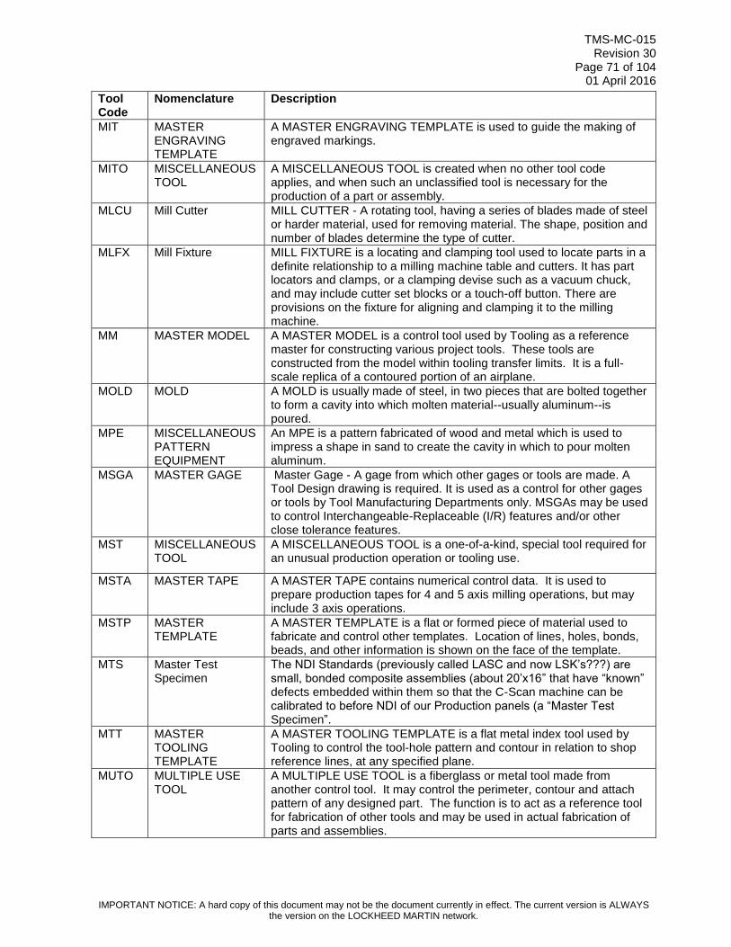
TMS-MC-015 Revision 30
Page 71 of 104 01 April 2016
IMPORTANT NOTICE: A hard copy of this document may not be the document currently in effect. The current version is ALWAYS the version on the LOCKHEED MARTIN network.
Tool Code
Nomenclature Description
MIT MASTER ENGRAVING TEMPLATE
A MASTER ENGRAVING TEMPLATE is used to guide the making of engraved markings.
MITO MISCELLANEOUS TOOL
A MISCELLANEOUS TOOL is created when no other tool code applies, and when such an unclassified tool is necessary for the production of a part or assembly.
MLCU Mill Cutter MILL CUTTER - A rotating tool, having a series of blades made of steel or harder material, used for removing material. The shape, position and number of blades determine the type of cutter.
MLFX Mill Fixture MILL FIXTURE is a locating and clamping tool used to locate parts in a definite relationship to a milling machine table and cutters. It has part locators and clamps, or a clamping devise such as a vacuum chuck, and may include cutter set blocks or a touch-off button. There are provisions on the fixture for aligning and clamping it to the milling machine.
MM MASTER MODEL A MASTER MODEL is a control tool used by Tooling as a reference master for constructing various project tools. These tools are constructed from the model within tooling transfer limits. It is a full-scale replica of a contoured portion of an airplane.
MOLD MOLD A MOLD is usually made of steel, in two pieces that are bolted together to form a cavity into which molten material--usually aluminum--is poured.
MPE MISCELLANEOUS PATTERN EQUIPMENT
An MPE is a pattern fabricated of wood and metal which is used to impress a shape in sand to create the cavity in which to pour molten aluminum.
MSGA MASTER GAGE Master Gage - A gage from which other gages or tools are made. A Tool Design drawing is required. It is used as a control for other gages or tools by Tool Manufacturing Departments only. MSGAs may be used to control Interchangeable-Replaceable (I/R) features and/or other close tolerance features.
MST MISCELLANEOUS TOOL
A MISCELLANEOUS TOOL is a one-of-a-kind, special tool required for an unusual production operation or tooling use.
MSTA MASTER TAPE A MASTER TAPE contains numerical control data. It is used to prepare production tapes for 4 and 5 axis milling operations, but may include 3 axis operations.
MSTP MASTER TEMPLATE
A MASTER TEMPLATE is a flat or formed piece of material used to fabricate and control other templates. Location of lines, holes, bonds, beads, and other information is shown on the face of the template.
MTS Master Test Specimen
The NDI Standards (previously called LASC and now LSK’s???) are small, bonded composite assemblies (about 20’x16” that have “known” defects embedded within them so that the C-Scan machine can be calibrated to before NDI of our Production panels (a “Master Test Specimen”.
MTT MASTER TOOLING TEMPLATE
A MASTER TOOLING TEMPLATE is a flat metal index tool used by Tooling to control the tool-hole pattern and contour in relation to shop reference lines, at any specified plane.
MUTO MULTIPLE USE TOOL
A MULTIPLE USE TOOL is a fiberglass or metal tool made from another control tool. It may control the perimeter, contour and attach pattern of any designed part. The function is to act as a reference tool for fabrication of other tools and may be used in actual fabrication of parts and assemblies.

TMS-MC-015 Revision 30
Page 72 of 104 01 April 2016
IMPORTANT NOTICE: A hard copy of this document may not be the document currently in effect. The current version is ALWAYS the version on the LOCKHEED MARTIN network.
Tool Code
Nomenclature Description
MYTT MYLAR TRANSFER TOOL
A MYLAR TRANSFER TOOL is a Mylar duplication of engineering configuration which is used to transfer hole patterns, show part location or orientation. Used for assembly of details and/or installation of details or assemblies. Made from an engineering flat pattern development or manufacturing engineering tooling model.
NCPA NUMERICAL CONTROL PATTERN
A NUMERICAL CONTROL PATTERN is used for digitizing a master tape for numerical control machines.
NHDI NOTCH DIE A NOTCH DIE is used for cutting a notch or cutout in the edge of a part.
PADI STEEL RULE DIE A STEEL RULE DIE is a length of spring steel tape used for marking drill holes or locating points across large parts or assemblies. The steel tape contains marks which have been applied in accordance with a tool design, and those marks indicate the points where scribe lines or punch indentations are to be applied.
PAEQ MISCELLANEOUS PATTERN EQUIPMENT
Miscellaneous Pattern Equipment describes patterns fabricated of wood and metal which are used to impress shapes in sand to create the cavities into which molten aluminum is poured to make cast parts.
PBD PIERCE & BLANK DIE
A PIERCE & BLANK DIE is a conventional tool used to pierce holes and blank the periphery of parts in a punch press.
PCDI PIERCE DIE A PIERCE DIE is used for piercing a hole or pattern of holes in a part.
PD PIERCE DIE A PIERCE DIE is a conventional punch-press tool used to pierce holes in metallic and non-metallic materials.
PDBH PRODUCTION BROACH
A PRODUCTION BROACH is an internal or external broach having a series of stepped cutting edges. It is pushed or pulled through a part to remove material.
PDDY PRODUCTION DOLLY
A PRODUCTION DOLLY is a movable dolly usually on wheels or casters which is used to hold, position, and/or transport any assembly which is not a component assembly. This dolly indexes to and maintains dimensional control of previously established points that are essential in order to control the accuracy of the assembly.
PDMD PLASTIC DRAW MOLD DIE
The PLASTIC DRAW MOLD DIE is a shape or form imparting tool. It may be either male (punch like) or female (a cavity) in configuration. The tool incorporates features to utilize a vacuum source, define part trim and/or EOP lines, or related edges of other engineering parts.
PDMO PRODUCTION MOLD
Any PRODUCTION MOLD for producing molded rubber, plastic, or metal. This includes auxiliary tooling such as investment mold dies.
PDMU Production Mock Up
A PRODUCTION MOCKUP is a dummy part or assembly which is used in the airplane in place of a production part or assembly to determine clearance relative to adjacent parts. PDMUs are usually made of wood and painted. No Tool Design drawing required.
PI PRODUCTION ILLUSTRATION
A PRODUCTION ILLUSTRATION is a pictorial or orthographic drawing prepared by the Tool Design Illustration Group and used by Engineering, Planning, Tooling and Manufacturing for instruction, layout, rigging, print interpretation, tool fabrication, part assembly, installation and machine set-up
PKD PANCAKE DIE A Pancake Die is a conventional type punch press tool which combines forming operations with piercing, blanking, or trimming.

TMS-MC-015 Revision 30
Page 73 of 104 01 April 2016
IMPORTANT NOTICE: A hard copy of this document may not be the document currently in effect. The current version is ALWAYS the version on the LOCKHEED MARTIN network.
Tool Code
Nomenclature Description
PM PLASTER MODEL A PLASTER MODEL is a male or female reference tool used to make other project tools. It is a full-scale model of an airplane part or assembly. It may be modified to allow for shrinkage or draft and shall contain information such as trim lines, beads, traps, etc.
PME PERMANENT MOLD EQUIPMENT
A Permanent Mold Equipment is a mold, usually made of steel, in two pieces that are bolted together to form a cavity into which molten aluminum is poured.
PP PRODUCTION PATTERN
A PRODUCTION PATTERN can be a flat or three-dimensional representation of a production part, or portion of a part, which maintains tolerances and shapes to facilitate the manufacturing process.
PRB PIN ROUTER BLOCK
A PIN ROUTER BLOCK is a flat guide tool used by Manufacturing to profile flat part blanks on a pin router or shaper.
PRDA UNCLASSIFIED HANDLING EQUIPMENT
UNCLASSIFIED HANDLING EQUIPMENT encompasses a variety of devices which are intended to facilitate the lifting or movement of large or heavy tools or parts. Such devices are generally designed and built to be used in conjunction with specific items, and would not be classified as standard-type equipment.
PRM Permanent Mold A permanent mold is usually made of steel or aluminum, and has a cavity in which rubber or plastic is injected or poured to form a given shape.
RATF ROTATE ACCESS TRANSPORT FIXTURE
ROTATE ACCESS AND TRANSPORT FIXTURE - Used to hold assembly fixtures for moving from station to station as well as raise, lower and rotate for best ergonomic positioning.
REFP PLASTER MODEL A PLASTER MODEL is a male or female reference tool used to make other project tools. It is a full-scale model of an airplane part or assembly. It may be modified to allow for shrinkage or draft and shall contain information such as trim lines, beads, traps, etc.
RJ RIVETING JIG A RIVETING JIG is a holding and clamping tool used by Manufacturing to prevent important attach points and contours on the production assembly from moving and distorting while being drilled and riveted.
RRB RADIAL ARM ROUTER BLOCK
A RADIAL-ARM ROUTER BLOCK is a flat guide block used by Manufacturing to profile part blanks.
RTM RESIN TRANSFER MOLD
A RESIN TRANSFER MOLD is a multi-segmented heated steel mold in which resin is injected to form a part under a combination of heat and pressure.
RWJ RESISTANCE WELD JIG
A RESISTANCE WELD JIG is a locating and clamping tool consisting of a framework with sufficient clamping and locating means to hold two or more parts in accurate relative position and to provide access for spot or resistance welding.
SB SPIN BLOCK A SPIN BLOCK is a forming tool for concentric parts whose size, shape and configuration are adaptable to this method of forming.
SF SAW FIXTURE A SAW FIXTURE is a guide tool used to nest and clamp parts or assemblies in a definite relationship to a saw or abrasive cut-off wheel.
SHB SHAPER BLOCK A SHAPER BLOCK is a guide block used by Manufacturing to profile formed sheet metal or extruded parts on a spindle shaper. The edges of the block guide the profiling cut by moving against a guide collar on the shaper.
SMT SPACEMATIC TEMPLATE
A SPACEMATIC TEMPLATE is a metal tool used to locate a hole pattern in a production part or assembly for drilling or drilling-countersinking.

TMS-MC-015 Revision 30
Page 74 of 104 01 April 2016
IMPORTANT NOTICE: A hard copy of this document may not be the document currently in effect. The current version is ALWAYS the version on the LOCKHEED MARTIN network.
Tool Code
Nomenclature Description
SP SAMPLE PART A SAMPLE PART is a Manufacturing or Tooling aid provided as a project tool. It is a dummy of a part or assembly and its configuration varies according to intended use. It is used by Manufacturing to make standard setups on machines and by Tooling to fabricate other tools.
SRD STEEL RULE DIE A STEEL RULE DIE is a length of spring steel tape used for marking drill holes or locating points across large parts or assemblies. The steel tape contains marks which have been applied in accordance with a tool design, and those marks indicate the points where scribe lines or punch indentations are to be applied.
SRM SHOP REFERENCE MODEL
A SHOP REFERENCE MODEL is a plaster or plastic cast record of a forming tool or formed airplane part.
SST STOCK SIZE TEMPLATE
A STOCK SIZE TEMPLATE is a flat index tool used by Manufacturing to produce a stock material-size blank suitable for a particular fabrication operation and, when specified, to stack-drill.
STF STRAIGHTENING FIXTURE
A STRAIGHTENING FIXTURE is used to bring molded parts into intended configuration. Because of the heat involved, mold dies tend to warp the parts they have created, necessitating the employment of this tool. It is a tool of narrow application, usually dedicated to one mold die and, hence, one part number.
STFB STRETCH FORM BLOCK
A STRETCH FORM BLOCK is a forming tool that may include supporting tooling units such as stretch jaw inserts (set), joggle forming devices, and snakes (flexible filler tool to maintain the shape of certain cross sections of extrusions or brake formed parts during the forming operation).
SUT SET-UP TEMPLATE
A SET-UP TEMPLATE is a flat metal template type tool used by Manufacturing to spot spray rivet locations or to position details on the standard scribe tables for the layout of Chem-Milled parts.
TF TEST FIXTURE The TEST FIXTURE is a tool used to hold a production part during the application of a test load.
TFA TEST FIXTURE AID
The TEST FIXTURE AID is a tool used to hold a production part during the application of a test load.
TFVA TRIM TOOL A TRIM TOOL is made of aluminum and designed to be used on a multi-axis machine. The tool will include a vacuum system to hold the part in place; used to trim medium sized flat composite parts.
TFVB TRIM TOOL A TRIM TOOL is made of aluminum, and designed to be used on a multi-axis machine. The tool will include a vacuum system to hold the part in place; used to trim small to medium sized contoured parts.
TFVC TRIM TOOL A TRIM TOOL is made of aluminum, and designed to be used on a multi-axis machine. The tool will include a vacuum system to hold the part in place. The tool face will be supported by an eggcrate backup structure and base. The tool is used to trim large contoured parts.
TFVD TRIM FIXTURE VACUUM ASSISTED
A VACUUM ASSISTED TRIM FIXTURE is used for N/C trimming and/or drilling of composite parts. It consists of a fiberglass tool face, vacuum system, egg crate substructure and steel base. Tooling holes index the part to the tool contour and a vacuum system holds the part in place. The tool vacuum system consists of pads that lie between fastener patterns and trim lines to ensure vacuum integrity during trimming and drilling operations.
THGA THREAD GAGE A THREAD GAGE is used for checking pitch diameter, lead and/or thread form of internal or external threaded parts.

TMS-MC-015 Revision 30
Page 75 of 104 01 April 2016
IMPORTANT NOTICE: A hard copy of this document may not be the document currently in effect. The current version is ALWAYS the version on the LOCKHEED MARTIN network.
Tool Code
Nomenclature Description
TLTP TOOL LOCATING TEMPLATE
A TOOL LOCATING TEMPLATE may be a single tool or a set of tools made of stable translucent material developed from a manufacturing engineering tooling model. The tool controls fiber direction of the unidirectional tape, and includes indexing provisions.
TMCM Tooling Machine Control Medium
Tooling Machine Control Medium
TMD TRIM DIE A TRIM DIE is a conventional-type punch press tool used to trim flat or formed sheet metal parts.
TMLO TOOLING MASTER LAYOUT
Soft tooling - Mylar
TMP TOOLING MODEL PART
A TOOLING MODEL PART is a tool that is a replica of a part or assembly (which may be abbreviated) used in the tool shop for coordination purposes only.
TOAC TOOLING ACCESSORY
A TOOLING ACCESSORY is used on or in conjunction with another tool.
TOFA TOOLING FORM A TOOLING FORM is constructed of modeling board, such as Ren 450. Used for fabricating and inspecting various tools.
TRF TURNING FIXTURE
A TURNING FIXTURE holds a production part during lathe, jig bore or milling operations. It is used to rotate the part freely or into predetermined attitudes for the performance of required operations.
TSJ TEST-SYSTEM ELECTRONICS
TEST_SYSTEM ELECTRONICS is special contract tooling used for testing parts, assemblies, or systems on a specific airplane project. It is used to ensure functional compliance with all Engineering and customer specifications. Mechanical, hydraulic, pneumatic, optical electric or electronic means are used for testing.
TTA TEST TOOL ACCESSORY
A TEST TOOL ACCESSORY is any component of a TEST TOOL used for the calibration or verification of electronic equipment.
TUFX Turning Fixture A TURNING FIXTURE is used to locate and clamp a part in a position relative to a cutting tool while turning the part. A Tool Design drawing is required.
VJ VICE JAWS VICE JAWS are custom-fitted to the contours of production parts in order to hold them securely or without damaging them during machining or drilling operations.
WJ WELD JIG A WELD JIG is a locating and clamping tool used to hold two or more parts in accurate relative position and provide access for flame or arc welding.
WT Web Template WEB REAR BEAM 65-584 for P3

TMS-MC-015 Revision 30
Page 76 of 104 01 April 2016
IMPORTANT NOTICE: A hard copy of this document may not be the document currently in effect. The current version is ALWAYS the version on the LOCKHEED MARTIN network.
Table 5.2 All Fort Worth Programs Tool Codes
Fort Worth All Programs Tool Codes
TOOL
CODE
F-
16
F-
22
F-
35
F-
2
DESIGN
Y = Yes
N = No
O = Option
CONTROL
TOOL
Y = Yes
N = No
DESCRIPTION
ABFX X Y N ASSEMBLY BORING FIXTURE - A tool that indexes to an aircraft component to bore critical holes that are inaccessible to the PMM machine.
ADDS X N N
AUTO DRILL DATA SET - Verified and controlled digital data set used by Marietta Auto Drill NC machinery for drilling, boring, countersinking or other type machining operations in structural assemblies.
ADTA X N N AUTO DRILL TAPE - Verified and controlled digital data used by Numerical Control for drilling, boring and countersink operations.
AJFX X Y N
ABRASIVE JET FIXTURE: A tool used for holding composite skin and understructure parts for trimming operations on automated N/C abrasive jet equipment. The tool will be a minimal contact fixture of composite material for holding the part and for coordination to the cell automation.
AJTF X Y N
ASSEMBLY JIG AND TRANSPORT FIXTURE - Major component tool used to locate and hold parts and subassemblies in place for drilling, assembly, and autodrill. Used for major components with unique SWBS number. Same as an AJFX but has the added features for line transfer and re-index to another component station.
APFX X X X X Y N
APPLY FIXTURE: A fixture which is applied to and located by a part or component of the assembly. It may also be used for drilling, cutting or marking the part to which it is applied; for locating other parts in their relative positions and performing drilling, cutting, riveting and bore-sighting or marking operations if requested; or for bonding aluminum shims to steel parts. For the F/A-22 Program, a tool design is not required for APFX's which are a flat plane and can be made from Engineering dimensions. Hole coordination can be referenced to control tools or the production tools. Apply fixtures used in conjunction with PMMRs, require designs regardless of their simplicity.
ARFX X Y N
AUTOMATIC RIVETING FIXTURE: A fixture to locate and clamp parts in their proper relative position for riveting. If provisions for drilling are included, use DRFX.
ASFX X X X X Y N ASSEMBLY FIXTURE: A fixture to locate and clamp parts in their proper relative position for assembly. If provisions for drilling are included, use DRFX.
ASMT X O N
ASSEMBLY TEMPLATE - A tool used in bench assembly, subassembly, and major assembly for locating or drilling holes, for transferring points, or for locating uses.

TMS-MC-015 Revision 30
Page 77 of 104 01 April 2016
IMPORTANT NOTICE: A hard copy of this document may not be the document currently in effect. The current version is ALWAYS the version on the LOCKHEED MARTIN network.
Fort Worth All Programs Tool Codes
TOOL
CODE
F-
16
F-
22
F-
35
F-
2
DESIGN
Y = Yes
N = No
O = Option
CONTROL
TOOL
Y = Yes
N = No
DESCRIPTION
ASTP X X X O N
ASSEMBLY APPLY TEMPLATE: A tool used in major assembly and subassembly for locating or drilling holes, for transferring points or for locating uses.
BDDI X Y N BEADING DIE: A tool used to form a bead on the end of large diameter tubing.
BEFM X Y N BENDING FORM: A tool to which the part is clamped and then bent to desired shape.
BHFX X Y N BROACHING FIXTURE: A device in which a part is clamped and located in relation to the cutting teeth of an internal or external broach.
BITO X O N BURNISHING TOOL: A tool used to smooth a surface by compressing the outer layer of metal.
BKDI X Y N BRAKE DIE: A tool used on a power brake or similar equipment for bending metal in straight line.
BLDI X O N BLANK DIE: A die which by shearing action cuts or blanks the outline of a part in flat pattern. Tool Design is required for F-35 Program.
BNFM X X X O N
BONDING FORM: A form or fixture used to hold an assembly of parts while being metal bonded, Epoxy bonded, etc. Tool Design is required for F-35 Program.
BNFX X X X X Y N BONDING FIXTURE: A fixture used to locate and hold details for secondary bonding.
BOBR X X Y N BORING BAR: A tool for holding one or more cutters in the proper position for enlarging a hole.
BOFX X X X X Y N BORING FIXTURE: A device used to properly locate and clamp work in relation to the cutting tool used for boring the part.
BUBK X N Y
BLUE BLOCK: A tool that is required to blue in other tools. This can be made from plaster, fiberglass, etc., and can be ordered as a supplemental or permanent tool as determined by degree of difficulty or repetitive usage. Formerly used only for permanent tools. Also, previously called CKFMs for bluing Dhows.
BZBK X N N
BRAZING BLOCK: A graphite block used to maintain the shape of lower surface of brazed panels during brazing operations (to be ordered as process aids only).
BZBX X O N
BRAZING BOX: Shall contain the assembly and brazing form under vacuum controlled atmospheric conditions. This box is made of stainless steel and is designed to maintain structural stability at temperatures in excess of 1850° F. (to be ordered as process aids only).
BZFM X Y N BRAZING FORM: Platen to maintain surface shape during the brazing operation. The brazing form may include accessories such as shims, spacers, cover

TMS-MC-015 Revision 30
Page 78 of 104 01 April 2016
IMPORTANT NOTICE: A hard copy of this document may not be the document currently in effect. The current version is ALWAYS the version on the LOCKHEED MARTIN network.
Fort Worth All Programs Tool Codes
TOOL
CODE
F-
16
F-
22
F-
35
F-
2
DESIGN
Y = Yes
N = No
O = Option
CONTROL
TOOL
Y = Yes
N = No
DESCRIPTION
sheets, and locators (to be ordered as process aids only).
CCJW X Y N CHUCK JAWS: A set of shaped blocks fastened to a chuck and used for clamping a part while cutting operations are being formed.
CDTO X X X Y N
COMPOSITE DEBULK TOOL: A tool used for the lay-up and cold debulk of an understructure detail part, prior to loading into a curing tool. The tool will consist of multiple NC machined details with a base plate.
CKFM X X X O N CHECK FORM: A tool used to check a part after forming or after heat treating and straightening.
CKGA X X X X Y N CHECK GAGE: A gage used to check position or spacing of objects or holes in relation to other objects or holes.
CKTP X X X O N CHECK TEMPLATE: A flat or formed piece of material used to check the shape of a part and/or joggles, holes, trim, etc.
CLAD X Y N COLLET ADAPTER: A special collet or pads for collet.
CMFX X X Y N CORE MILL FIXTURE: A tool to locate and hold core while removing excess material with a mill cutter.
CNDI X O N
COMBINATION DIE: Any die combining two or more operations, such as piercing and blanking, blanking and forming, etc. Die may be either progressive or compound. Constructions similar to blank die or form die.
COFX X X X Y N
COMPONENT FIXTURE: A tool to hold, position and/or transport the whole component after structural assembly is complete. The tool indexes to and maintains dimensional control of previously established points that are essential in order to control the accuracy of the components.
COJI X X X Y N
COMPONENT JIG: A tool used to locate and hold parts and/or assemblies in their proper relative position for drilling and/or assembly. COJI is the same as DRFX or ASFX except that it is used to build a major component.
COMG X X X X Y Y
COMPONENT MASTER GAGE - A COMG is the same as a MSGA except that it is used to make and control tools that are directly related to the manufacture of major (O.I.L.) components. The COMG simulates the OML of understructure of the aircraft (e.g. bulkheads, longerons, spars, ribs, hinge points). They control the I-R hole pattern (and perimeters for F-35 only) of I-R panels and covers.
COTA X X X X N N
COMPOSITE TAPE: Tapes on which Numerical Control data is stored. Used by Numerical Control to prepare production tapes for the CAE (Composite Broadgoods Cutter).

TMS-MC-015 Revision 30
Page 79 of 104 01 April 2016
IMPORTANT NOTICE: A hard copy of this document may not be the document currently in effect. The current version is ALWAYS the version on the LOCKHEED MARTIN network.
Fort Worth All Programs Tool Codes
TOOL
CODE
F-
16
F-
22
F-
35
F-
2
DESIGN
Y = Yes
N = No
O = Option
CONTROL
TOOL
Y = Yes
N = No
DESCRIPTION
COTG X X X Y Y
COMPONENT TOOLING GAGE: A COTG is the same as a TOGA except that it is used to control tools that are directly related to the manufacture of major (OIL) components.
CRRL X Y N CONTOUR ROLLS: A set of rolls used to form a contour or change an angle in drawn or extruded section.
CSTL X X O N CORE STEP TOOL: A tool used for marking the location of core step cuts and for core separation.
CSTO X X X Y N
COMPOSITE SKIN TOOL: A tool used for curing composite skin parts. The tool will consist of a graphite face and understructure with a hard caul sheet for internal pressure.
CTA@ X Y N
COMPOSITE CURE TOOL, ALUMINUM - A tool for the fabrication of composite parts requiring elevated cure temperatures. Tool is NC machined from plate or billet, secured to a base plate, and has casters for mobility. A CTA@ for smaller parts may be NC machined from plate and used on a project plate. The @ indicator is a placeholder for the letters "A" through "L" (NOTE: Complexity Codes M thru X are FWT) which provide a twelve point value system as defined by 5-4.14.6 F-35 Tool Code Complexity Definition Table.
CTI@ X Y N
COMPOSITE CURE TOOL, INVAR - A tool for the fabrication of composite parts requiring elevated cure temperatures. It is of a welded construction including an NC machined face sheet, eggcrate structure, tubular base for stability, and may contain casters for mobility. For parts up to 400 degrees F., the tool shall be constructed of a 36 percent nickel alloy steel (Invar 36 or equivalent). For parts with cure temperatures that exceed 400 degrees F., the tool shall be constructed of a 42 percent nickel alloy steel (Invar 42 or equivalent). The @ indicator is a placeholder for the letters "M" through "X" (NOTE: Complexity Codes M thru X are FWT) which provide a twelve point value system as defined by the JSF Tool Code Size and Complexity Table.
CTCA X Y N
COMPOSITE CURE TOOL: Used for the fabrication of large, extremely complex contoured composite parts requiring elevated cure temperatures up to 375° Fahrenheit. The tool consists of an N/C machined face sheet, eggcrate substructure, tubular steel base and casters. The tool face sheet and eggcrate substructure are of laminated graphite construction and are permanently attached to the tubular steel base to improve its dimensional stability during service.

TMS-MC-015 Revision 30
Page 80 of 104 01 April 2016
IMPORTANT NOTICE: A hard copy of this document may not be the document currently in effect. The current version is ALWAYS the version on the LOCKHEED MARTIN network.
Fort Worth All Programs Tool Codes
TOOL
CODE
F-
16
F-
22
F-
35
F-
2
DESIGN
Y = Yes
N = No
O = Option
CONTROL
TOOL
Y = Yes
N = No
DESCRIPTION
CTCB X Y N
COMPOSITE CURE TOOL for the fabrication of small to medium complex composite parts requiring elevated cure temperatures up to 375° F. It consists of an N/C machined face sheet, eggcrate substructure and tubular steel base. The tool face sheet and eggcrate substructure are of laminated graphite construction and are permanently attached to the tubular steel base to improve its dimensional stability during service.
CTIA X N N NICKEL IRON ALLOY CURE TOOL for the fabrication of small to medium size planar composite parts requiring elevated cure temperatures.
CTIB X N N
NICKEL IRON ALLOY CURE TOOL for the fabrication of small to medium size composite parts requiring elevated cure temperatures. For F/A-22, the usage of this tool is limited to parts with a flange (open angle or 90°) shorter than 2 inches in length and contoured surfaces.
CTIC X Y N
NICKEL IRON ALLOY CURE TOOL for the fabrication of small to medium size composite parts requiring elevated cure temperatures. For F/A-22, the usage of this tool is limited to parts with flange (closed angle or longer than 2 inches) and parts with complex contour.
CTID X Y N
NICKEL IRON ALLOY CURE TOOL for the fabrication of medium size composite parts requiring elevated cure temperatures. For F/A-22, use for planar parts only.
CTIE X Y N
NICKEL IRON ALLOY CURE TOOL for the fabrication of medium to large size composite parts for F/A-22 requiring elevated cure temperatures. For F/A-22, the usage of this tool is limited to parts with a flange and parts with complex contour.
CTIF X Y N
NICKEL IRON ALLOY CURE TOOL for the fabrication of large composite parts for F/A-22 requiring elevated cure temperatures. For F/A-22, the usage of this tool is limited to parts with a flange and parts with complex contour.
CTIG X Y N
NICKEL IRON ALLOY CURE TOOL for the fabrication of composite parts requiring elevated cure temperatures. For F/A-22 usage is limited to long, narrow composite parts.
CTIM X Y N
A CURE TOOL for planer or very mildly contoured parts, less than 3 ft. in length and width. The tool shall be constructed of a 36 percent nickel iron alloy plate stock with a cure temperature of up to 400 degrees F. For F-35: tool dimensions = < 1 M; size = small; complexity = simple (planar or very mild contour).
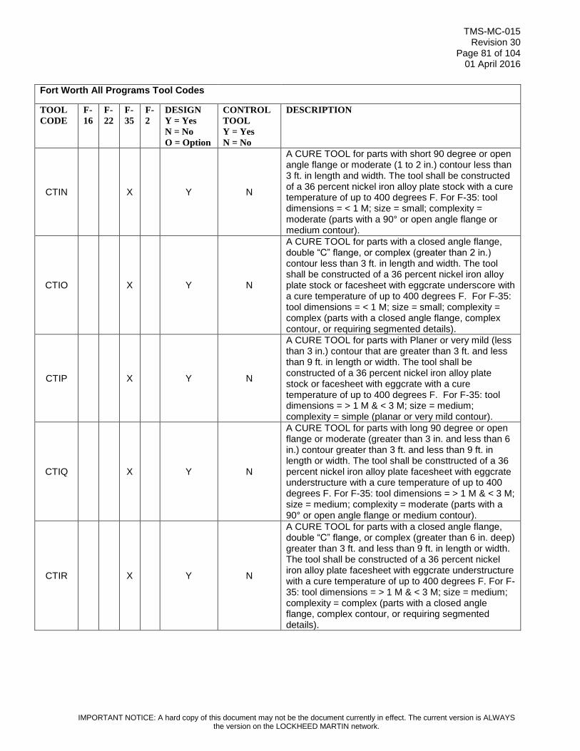
TMS-MC-015 Revision 30
Page 81 of 104 01 April 2016
IMPORTANT NOTICE: A hard copy of this document may not be the document currently in effect. The current version is ALWAYS the version on the LOCKHEED MARTIN network.
Fort Worth All Programs Tool Codes
TOOL
CODE
F-
16
F-
22
F-
35
F-
2
DESIGN
Y = Yes
N = No
O = Option
CONTROL
TOOL
Y = Yes
N = No
DESCRIPTION
CTIN X Y N
A CURE TOOL for parts with short 90 degree or open angle flange or moderate (1 to 2 in.) contour less than 3 ft. in length and width. The tool shall be constructed of a 36 percent nickel iron alloy plate stock with a cure temperature of up to 400 degrees F. For F-35: tool dimensions = < 1 M; size = small; complexity = moderate (parts with a 90° or open angle flange or medium contour).
CTIO X Y N
A CURE TOOL for parts with a closed angle flange, double “C” flange, or complex (greater than 2 in.) contour less than 3 ft. in length and width. The tool shall be constructed of a 36 percent nickel iron alloy plate stock or facesheet with eggcrate underscore with a cure temperature of up to 400 degrees F. For F-35: tool dimensions = < 1 M; size = small; complexity = complex (parts with a closed angle flange, complex contour, or requiring segmented details).
CTIP X Y N
A CURE TOOL for parts with Planer or very mild (less than 3 in.) contour that are greater than 3 ft. and less than 9 ft. in length or width. The tool shall be constructed of a 36 percent nickel iron alloy plate stock or facesheet with eggcrate with a cure temperature of up to 400 degrees F. For F-35: tool dimensions = > 1 M & < 3 M; size = medium; complexity = simple (planar or very mild contour).
CTIQ X Y N
A CURE TOOL for parts with long 90 degree or open flange or moderate (greater than 3 in. and less than 6 in.) contour greater than 3 ft. and less than 9 ft. in length or width. The tool shall be consttructed of a 36 percent nickel iron alloy plate facesheet with eggcrate understructure with a cure temperature of up to 400 degrees F. For F-35: tool dimensions = > 1 M & < 3 M; size = medium; complexity = moderate (parts with a 90° or open angle flange or medium contour).
CTIR X Y N
A CURE TOOL for parts with a closed angle flange, double “C” flange, or complex (greater than 6 in. deep) greater than 3 ft. and less than 9 ft. in length or width. The tool shall be constructed of a 36 percent nickel iron alloy plate facesheet with eggcrate understructure with a cure temperature of up to 400 degrees F. For F-35: tool dimensions = > 1 M & < 3 M; size = medium; complexity = complex (parts with a closed angle flange, complex contour, or requiring segmented details).

TMS-MC-015 Revision 30
Page 82 of 104 01 April 2016
IMPORTANT NOTICE: A hard copy of this document may not be the document currently in effect. The current version is ALWAYS the version on the LOCKHEED MARTIN network.
Fort Worth All Programs Tool Codes
TOOL
CODE
F-
16
F-
22
F-
35
F-
2
DESIGN
Y = Yes
N = No
O = Option
CONTROL
TOOL
Y = Yes
N = No
DESCRIPTION
CTIS X Y N
A CURE TOOL for parts with Planar or very mild (less than 4 in. deep) contour that are larger than 9 ft. and less than 30 ft. in length or width. The tool shall be constructed of a 36 percent nickel iron alloy plate facesheet with eggcrate understructure with a cure temperature of up to 400 degrees F. For F-35: tool dimensions = > 3 M & < 10 M; size = large; complexity = simple (planar or very mild contour).
CTIT X Y N
A CURE TOOL for parts with long 90 degree or open angle flange or moderate (greater than 4 in. and less than 12 in. deep) contours greater than 9 ft. and less than 30 ft. in length or width. The tool shall be constructed of a 36 percent nickel iron alloy plate facesheet with eggcrate understructure with a cure temperature of up to 400 degrees F. For F-35: tool dimensions = > 3M & < 10 M; size = large; complexity = moderate (parts with a 90° or open angle flange or medium contour).
CTIU X Y N
A CURE TOOL for parts with a closed angle flange, double “C” flange,or complex (greater than 12 in. deep) contour greater than 9 ft. in length or width. The tool shall be constructed of a 36 percent nickel iron alloy plate facesheet with eggcrate understructure with a cure temperature of up to 400 degrees F. For F-35: tool dimensions = > 3M & < 10 M; size = large; complexity = complex (parts with a closed angle flange, complex contour, or requiring segmented details).
CTIV X Y N
A CURE TOOL for parts with Planar or very mild (less than 6 in. deep) contour greater than 30 ft. in length or width. The tool shall be constructed of a 36 percent nickel iron alloy plate facesheet with eggcrate understructure with a cure temperature of up to 400 degrees F. For F-35: tool dimensions = > 10 M; size = very large; complexity = simple (planar or very mild contour).
CTIW X Y N
A CURE TOOL for parts with 90 degree or open angle flange or moderate (greater than 6 in. and less than 24 in. deep) contour greater than 30 ft. in length or width. The tool shall be constructed of a 36 percent nickel iron alloy plate facesheet with eggcrate understructure with a cure temperature of up to 400 degrees F. For F-35: tool dimensions = > 10 M; size = very large; complexity = moderate (parts with a 90° or open angle flange or medium contour).
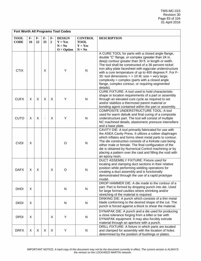
TMS-MC-015 Revision 30
Page 83 of 104 01 April 2016
IMPORTANT NOTICE: A hard copy of this document may not be the document currently in effect. The current version is ALWAYS the version on the LOCKHEED MARTIN network.
Fort Worth All Programs Tool Codes
TOOL
CODE
F-
16
F-
22
F-
35
F-
2
DESIGN
Y = Yes
N = No
O = Option
CONTROL
TOOL
Y = Yes
N = No
DESCRIPTION
CTIX X Y N
A CURE TOOL for parts with a closed angle flange, double “C” flange, or complex (greater than 24 in. deep) contour greater than 30 ft. in length or width. The tool shall be constructed of a 36 percent nickel iron alloy plate facesheet with eggcrate understructure with a cure temperature of up to 400 degrees F. For F-35: tool dimensions = > 10 M; size = very large; complexity = complex (parts with a closed angle flange, complex contour, or requiring segmented details).
CUFX X X X X Y N
CURE FIXTURE: A tool used to hold characteristic shape or location requirements of a part or assembly through an elevated cure cycle as required to set and/or stabilize a thermoset parent material or bonding agent contained within the part or assembly.
CUTO X X X Y N
COMPOSITE UNDERSTRUCTURE TOOL: A tool used for warm debulk and final curing of a composite understructure part. The tool will consist of multiple NC machined details, elastomeric pressure intensifiers and a base plate.
CVDI X O N
CAVITY DIE: A tool primarily fabricated for use with the ASEA Cavity Press. It utilizes a rubber diaphragm which inflates and forms sheet metal parts to contour. The die construction consists of a Kirksite cast being either male or female. The final configuration of the die is obtained by Numerical Control machining or by placing a pattern over the cast and filling the void with an epoxy resin.
DAFX X X X O N
DUCT ASSEMBLY FIXTURE: Fixture used for locating and clamping duct sections in their relative position while performing welding operations for creating a duct assembly and is functionally demonstrated through the use of a rapid prototype model.
DHDI X N N
DROP HAMMER DIE: A die made to the contour of a part. Part is formed by dropping punch into die. Used for large formed cavities where shrinking and/or stretching of the material is required.
DKDI X N N
DINKING DIE: A punch which consists of a thin metal blade conforming to the desired shape of the cut. The punch is forced against a block to shear the material.
DPDI X X Y N
DYNAPAK DIE: A punch and a die used for producing a close tolerance forging from a billet or bar with DYNAPAK equipment. It may also forcibly extrude material through an aperture with a punch.
DRFX X X X X Y N DRILL FIXTURE: A fixture in which parts are located and clamped for assembly with the location of holes determined by the position of bushings or plates.

TMS-MC-015 Revision 30
Page 84 of 104 01 April 2016
IMPORTANT NOTICE: A hard copy of this document may not be the document currently in effect. The current version is ALWAYS the version on the LOCKHEED MARTIN network.
Fort Worth All Programs Tool Codes
TOOL
CODE
F-
16
F-
22
F-
35
F-
2
DESIGN
Y = Yes
N = No
O = Option
CONTROL
TOOL
Y = Yes
N = No
DESCRIPTION
DRJI X X X X Y N
DRILL JIG: A jig in which a part is located and clamped while drilling, reaming, counterboring, countersinking or similar operations are performed. The tool is provided with hardened bushings or other means for guiding the cutting tools.
DRPE X X X X O N
DRILL PLATE: A flat piece of material provided with bushings or adapter size holes, used for drilling and/or reaming a hole or a pattern of holes in part. Tool is indexed to the part by means of pins or by using the edge(s) of the plate for alignment. Tool Design is required for F-35 Program.
DUPA X X O N
DUPLICATING PATTERN: A cam of variable width or irregular shape used to control the direction of travel and/or depth of cutting tool in machining a surface and/or perimeter of a part.
DWDI X Y N
DRAW DIE: A die in which the punch is to the desired inside shape of a part and the die section is to outside shape with proper clearance. The material is held by pressure pads and the punch draws the material into the die.
DWFM X N N DRAW FORM: A punch and a draw ring used in forming a part on the Hi-Draw machines.
EMAS X Y N
ELECTRONIC MATE AND ALIGNMENT SYSTEM - An electronic aircraft mating and alignment system which includes jacks, laser tracker, computers, and software.
ENMO X Y N ENCAPSULATION MOLD: A permanent type form mold used to encapsulate harness connectors or electronic modules.
ETTP X X O N
ETCH TEMPLATE: A tool used in trimming the masking on parts prior to chemical etching. The tool will match the interior or exterior curvature of the parts and will contain coordinated locating holes. The interior and/or exterior edges of this tool exactly locate the lines to which the mask is to be trimmed. The edges of the tool will be color coded to indicate sequenced trimming operation, and will incorporate allowance for etch back on part during the etching. Tool Design is required for F-35 Program.
FABT X N N
FINISHES ASSEMBLY BOOT TEMPLATE - A mylar or template duplication of engineering or process specification configuration which is used to define flat pattern sizes of Finishes Boots. Used for cutting, kitting, and positioning of bonded detailed boot pieces applied to Aircraft Assemblies. Derived from an engineering 3D data model, flat pattern development, or Manufacturing Engineering Data Model (MEDM) which will also contain a dataset configured for an

TMS-MC-015 Revision 30
Page 85 of 104 01 April 2016
IMPORTANT NOTICE: A hard copy of this document may not be the document currently in effect. The current version is ALWAYS the version on the LOCKHEED MARTIN network.
Fort Worth All Programs Tool Codes
TOOL
CODE
F-
16
F-
22
F-
35
F-
2
DESIGN
Y = Yes
N = No
O = Option
CONTROL
TOOL
Y = Yes
N = No
DESCRIPTION
automated flatbed cutter. Dataset will also be configured to enable planning graphics.
FCGA X X X X Y Y
FACILITY GAGE: A tool used for the fabrication of tools, to establish intermediate or related points employing optical tooling methods. Used for tool fabrication and reference information.
FDBT X N N
FINISHES DETAIL BOOT TEMPLATE - A mylar or template duplication of engineering or process specification configuration which is used to define flat pattern sizes of Finishes Boots. Used for cutting, kitting, and bonding of detailed boot pieces applied to Detail Parts or Components. Derived from an engineering 3D data model, flat pattern development, or Manufacturing Engineering Data Model (MEDM) which will also contain a dataset configured for an automated flatbed cutter. Dataset will also be configured to enable planning graphics.
FFTO X N N
FACED FORM TOOL: A tool used to draw form simple, thin gage material, parts on the Hydro-Press. (A non-designed tool made of Masonite, Richlite, aluminum, etc., with a plastic face. May be single or multiple action).
FGDI X X Y N FORGING DIE: A punch and a die used for producing a forging from a billet or bar. It may also forcibly extrude material through an aperture with a punch.
FITA X N N FINISH TAPE - Verified and controlled digital data for cutting component or aircraft finish materials on the Gerber cutting machine for finish applications.
FLTP X X X X O N
FLAT TEMPLATE: A flat piece of material, the perimeter of which is the shape of the part in flat pattern. Location of lines, holes, bends and other information as required are shown on the face of template. Holes may be actual or adapter size depending on use. May be used to trim perimeter of core material.
FMCA X N N FORMING CAM: A template used to control the rate of bend (radius of parts fabricated with stretcher forms on cam operated stretch presses).
FMDI X X Y N
FORM DIE: A die, consisting of punch and die, used for forming a part to a desired shape. Die may be made to form more than one part at a time. Template for the blank part is developed from the die.
FMMD X O N FORM MANDREL: A mandrel used to support a part during swage, bend, form, stretch, or wipe operations.
FMRL X Y N
FORM ROLL: A set of rolls which progressively form the desired cross section shape of a part. (Guide bars, mandrels, spacers, etc. will be a part of the basic tool.)

TMS-MC-015 Revision 30
Page 86 of 104 01 April 2016
IMPORTANT NOTICE: A hard copy of this document may not be the document currently in effect. The current version is ALWAYS the version on the LOCKHEED MARTIN network.
Fort Worth All Programs Tool Codes
TOOL
CODE
F-
16
F-
22
F-
35
F-
2
DESIGN
Y = Yes
N = No
O = Option
CONTROL
TOOL
Y = Yes
N = No
DESCRIPTION
FMST X Y N FILM SET: Consists of a master negative plus working negatives and positives (both single and multiple), for producing parts by the photo-etch process.
FMTO X Y N
FORM TOOL: (1) A piece of steel or some harder material having a cutting edge shaped to the form desired on a finished turned part, (2) a tool which forms by exerting pressure on a relative small section of the part at one time.
FPML X Y N
FIBER PLACEMENT MANDREL - A segmented tool that provides interface to the fiber placement machinery for the automated tow placement process and elevated temperature cure.
FRDI X Y N FLARING DIE: A die in which a part is clamped and flared by means of the action of a punch or roller.
FXFM X Y N
FIXTURE FRAME - A floor based or floor anchored dock for mounting moveable assembly tools such as an AJTF or ASTF. Generally does not have parts locators but does provide index points for the moving assembly jig. These fixtures frequently contain utilities such as air, electrical, and lighting.
GRFX X Y N GRINDING FIXTURE: A fixture used to locate and clamp a part in a position relative to a grinding wheel.
HFDI X Y N HOT FORM DIE: A heated die for hot forming metal.
HFHT X Y N HANDLING FIXTURE HOIST TOOL - A part or assembly specific lifting device.
HFIA X Y N
HOLDING FIXTURE INTEGRATION & ASSEMBLY - A floor based tool that supports an aircraft component during systems and equipment installation and check out. Generally this tool will not provide part or subassembly locators.
HFLA X Y N
HOLDING FIXTURE LINE ACCESSORY - Used in a lean production environment to move tools through the production line. Eliminates the need for overhead handling. Normally a wheel based dolly.
HFLD X Y N
HANDLING FIXTURE LINE DOLLY - Used in a lean production environment to move large parts such as skins. Eliminates the need for overhead handling. Normally a wheel based dolly which is designed to allow part transfer to major components or fixtures.
HJTF X Y N
HOLDING JIG and TRANSPORT FIXTURE - Tool used to locate and hold major tools (AJFX, AJTF, or ASTF) and subassemblies in place for drilling, assembly, precision milling, and autodrill. Typically a large superstructure which also mates or completes major airframe parts.
HNFM X O N HAND FORM: A block shaped to the inside or outside of a part which is to be formed by hand.

TMS-MC-015 Revision 30
Page 87 of 104 01 April 2016
IMPORTANT NOTICE: A hard copy of this document may not be the document currently in effect. The current version is ALWAYS the version on the LOCKHEED MARTIN network.
Fort Worth All Programs Tool Codes
TOOL
CODE
F-
16
F-
22
F-
35
F-
2
DESIGN
Y = Yes
N = No
O = Option
CONTROL
TOOL
Y = Yes
N = No
DESCRIPTION
HOFX X X X X Y N
HOLDING FIXTURE: A fixture used for clamping and/or locating parts for machining. Limited to specific applications such as N/C drilling, EDM, etc. Used only when other Tool Codes will not suffice. May be a floor based tool that supports an aircraft component during final component assembly for F-35.
HPFM X X O N
HYDRO-PRESS FORM: A block made to the size and shape of a part. The part is made by pressure or rubber against the sheet stock from which the part is made, causing the part to be formed and/or cut to the size and shape of the form block. Part should be nested or located on the form block. Tool Design is required for F-35 Program.
HRBD X X O N
HARNESS BOARD: A tool used for the fabrication of electrical harnesses showing length of wire, location of connectors, and all other information needed to fabricate harnesses. Tool Design is required for F-35 Program.
HRTO X X X Y N
HAND ROUTER TOOL: A tool used for holding and/or positioning the work piece and also for guiding the hand routers during the hand routing operations. This includes both conventionally hand routing and skate routing. Typically for routing only with no other features.
HTBK X Y N HOT BLOCK: A heated block for holding the temperature of extrusions or sheet metal cross section while being stretched.
HTFM X Y N HOT FORM: A heated form for holding the temperature of sheet metal skins being stretched.
HTFX X X Y N
HEAT TREAT FIXTURE: A fixture in which parts are held during heat treating, normalizing, quenching, tempering or straightening, and in which a part may be checked after heat treating or straightening operation.
HXBF Y N HEXPLY BONDING FIXTURE - An aluminum tool used to bond a stabilizing ply to honeycomb core.
IFCT X X Y Y INTERFACE CONTROL TOOL: A tool used to control contour, penetrations and all other features used to mate major components or subassemblies.
IJMO X X Y N INJECTION MOLD: Closed cavity-type matched die mold into which material is injected under pressure from an outside source.
INFX X Y N INSPECTION FIXTURE - A check fixture for castings and forgings.
INGA X X X Y N INSPECTION GAGE: Any tool used by the Inspection Department for checking parts or assemblies.
IPFM X X N N IMPACT FORM: A block shaped to the part which is formed or cut by rubber under heavy impact on the drop hammer or some similar type of press. Part
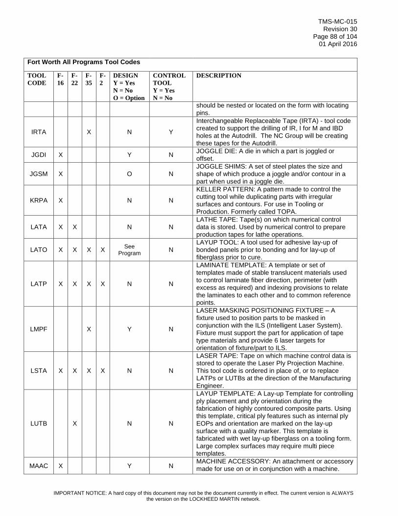
TMS-MC-015 Revision 30
Page 88 of 104 01 April 2016
IMPORTANT NOTICE: A hard copy of this document may not be the document currently in effect. The current version is ALWAYS the version on the LOCKHEED MARTIN network.
Fort Worth All Programs Tool Codes
TOOL
CODE
F-
16
F-
22
F-
35
F-
2
DESIGN
Y = Yes
N = No
O = Option
CONTROL
TOOL
Y = Yes
N = No
DESCRIPTION
should be nested or located on the form with locating pins.
IRTA X N Y
Interchangeable Replaceable Tape (IRTA) - tool code created to support the drilling of IR, I for M and IBD holes at the Autodrill. The NC Group will be creating these tapes for the Autodrill.
JGDI X Y N JOGGLE DIE: A die in which a part is joggled or offset.
JGSM X O N JOGGLE SHIMS: A set of steel plates the size and shape of which produce a joggle and/or contour in a part when used in a joggle die.
KRPA X N N
KELLER PATTERN: A pattern made to control the cutting tool while duplicating parts with irregular surfaces and contours. For use in Tooling or Production. Formerly called TOPA.
LATA X X N N LATHE TAPE: Tape(s) on which numerical control data is stored. Used by numerical control to prepare production tapes for lathe operations.
LATO X X X X See
Program N
LAYUP TOOL: A tool used for adhesive lay-up of bonded panels prior to bonding and for lay-up of fiberglass prior to cure.
LATP X X X X N N
LAMINATE TEMPLATE: A template or set of templates made of stable translucent materials used to control laminate fiber direction, perimeter (with excess as required) and indexing provisions to relate the laminates to each other and to common reference points.
LMPF X Y N
LASER MASKING POSITIONING FIXTURE – A fixture used to position parts to be masked in conjunction with the ILS (Intelligent Laser System). Fixture must support the part for application of tape type materials and provide 6 laser targets for orientation of fixture/part to ILS.
LSTA X X X X N N
LASER TAPE: Tape on which machine control data is stored to operate the Laser Ply Projection Machine. This tool code is ordered in place of, or to replace LATPs or LUTBs at the direction of the Manufacturing Engineer.
LUTB X N N
LAYUP TEMPLATE: A Lay-up Template for controlling ply placement and ply orientation during the fabrication of highly contoured composite parts. Using this template, critical ply features such as internal ply EOPs and orientation are marked on the lay-up surface with a quality marker. This template is fabricated with wet lay-up fiberglass on a tooling form. Large complex surfaces may require multi piece templates.
MAAC X Y N MACHINE ACCESSORY: An attachment or accessory made for use on or in conjunction with a machine.

TMS-MC-015 Revision 30
Page 89 of 104 01 April 2016
IMPORTANT NOTICE: A hard copy of this document may not be the document currently in effect. The current version is ALWAYS the version on the LOCKHEED MARTIN network.
Fort Worth All Programs Tool Codes
TOOL
CODE
F-
16
F-
22
F-
35
F-
2
DESIGN
Y = Yes
N = No
O = Option
CONTROL
TOOL
Y = Yes
N = No
DESCRIPTION
MAKM X N N
Masking Kit Model - is defined as a "MEDM" Mfg. Engr. Data Model developed and defined by Manufacturing Engineering. The Model will consist of a flat pattern developed with locating tabs, overlaps, gaps, etc. as required by the Manufacturing Engineer. The MEDM must be named with Part Number and Tool number to identify the model configuration. The completed model will be used to create a "Stencil Configuration Kit," which will consist of a ".DFX" file (made from the MEDM) to drive the automated cutting machine to cut the masking material kit, to be used during paint operations. Note: This masking tool template to be issued to shop orders.
MATO X X X N N
MASKING TOOL: A tool used for the masking of certain areas of a part during operations such as shot peen or other operations where partial masking is required to prevent bonding cement, paint, etc., from being applied to a specific area.
MATP X X N N MASKING TEMPLATE: A template which covers specific surfaces of a part to prevent bonding cement, paint, etc., from being applied to these specific areas.
MCTO X X X Y N METAL COMPOSITE TOOL: An MCTO is a tool used in curing composite skin parts. The tool will consist of a metal face and metal understructure.
MEXT Y N
MANDREL EXTRACTION TOOL - A tool used to extract mandrel segments from a cured composite part. Consists of tool attachment details and a method to counterbalance the cure fixture segments.
MFSE X X X N N
MANUFACTURING SUPPORT EQUIPMENT: Tooling controlled manufacturing support equipment. This code will be used for consistency in tooling records and will not appear on the equipment identification plaque.
MITO X X X X O N
MISCELLANEOUS TOOL: A tool which is necessary for the production of a part or an assembly. This tool code is to be used only when no other tool code applies.
MITP X N N
MINIATURE TEMPLATE: A flat or formed piece of material with either length or width (or both) dimensions shorter than the corresponding dimensions on the part. Actual dimensions of the part are to be stamped on the tool.
MKTA X N N MARKING TAPE - Verified and controlled digital program used by multi-axis NC machinery for marking clip and bracket location on primary structure.
MLCU X X X Y N MILL CUTTER: A rotating tool, having a series of blades made of steel or harder material, used for

TMS-MC-015 Revision 30
Page 90 of 104 01 April 2016
IMPORTANT NOTICE: A hard copy of this document may not be the document currently in effect. The current version is ALWAYS the version on the LOCKHEED MARTIN network.
Fort Worth All Programs Tool Codes
TOOL
CODE
F-
16
F-
22
F-
35
F-
2
DESIGN
Y = Yes
N = No
O = Option
CONTROL
TOOL
Y = Yes
N = No
DESCRIPTION
removing material. The shape, position, and number of blades determine the type of cutter.
MLFX X X X Y N MILL FIXTURE: A fixture used to locate and clamp a part or an assembly in proper relation to the mill cutter(s).
MPTP X X X N N
MULTI-PURPOSE TEMPLATE: A template normally fabricated from sheet metal that is developed to include locating of multiple secondary brackets, holes and/or cut-outs for attachment of multiple aircraft systems or equipment items to a structural part or subassembly.
MRFM X O N MACHINE ROUTER FORM: Locates and holds part and provides a profiling pattern for use on machine routers.
MRFX X X O N MACHINE ROUTER FIXTURE: Locates and holds parts and provides a profiling pattern for use on machine routers.
MRTO X X X X O Y
MISCELLANEOUS REFERENCE TOOL: A tool used for the fabrication of tools, to establish intermediate or related point. Used for fabrication or reference only. (Use only when no other tool code is applicable.) Formerly called TOAC or a supplemental tool.
MSCT X X X O Y
MASTER CONTROL TOOL: An MSCT controls the air surface, OML, or may be made to IML for application purposes. A Master Dimension Database (MDDB) or Manufacturing Engineering Tooling Model (METM) will control the MSCT for contour and reference information and may control part EOP, cutouts, tooling and fastener holes.
MSFM X X X N Y MASTER FORM: A form made full size of a portion of an airplane. Used to control tooling form or production mockup.
MSGA X X X X Y Y MASTER GAGE: A gage from which other gages or tools are made. It is used as a control for other gages or tools by Tool Manufacturing Departments only.
MSPE X X X X Y Y
MASTER PLATE: A plate in which a pattern of holes is accurately controlled. Used by Tool Manufacturing Departments only for control of other tools. May include information such as mold line, perimeter of part, location of cutouts, reference lines, etc.
MSTA X X X X N Y
MASTER TAPE: Tape(s) on which numerical control data is stored. Used by Tool Manufacturing Departments to prepare production tapes for 4 & 5 axis milling operations, may include 3 axis operations.
MSTP X X X N Y
MASTER TEMPLATE: A flat or formed piece of material used by Tool Manufacturing Departments to fabricate and control other templates. Location of lines, holes, bonds, beads, and other information are shown on the face of the template.

TMS-MC-015 Revision 30
Page 91 of 104 01 April 2016
IMPORTANT NOTICE: A hard copy of this document may not be the document currently in effect. The current version is ALWAYS the version on the LOCKHEED MARTIN network.
Fort Worth All Programs Tool Codes
TOOL
CODE
F-
16
F-
22
F-
35
F-
2
DESIGN
Y = Yes
N = No
O = Option
CONTROL
TOOL
Y = Yes
N = No
DESCRIPTION
MTFX X Y N
MATE FIXTURE - A fixture to locate and hold two or more tools and/or components in their relative position to each other to enable them to be pinned, bolted or mated together.
MUTO X X X O N
MULTIPLE USE TOOL: A MUTO is a fiberglass or metal tool made from an MSCT or other control tools. A MUTO may control the perimeter, contour and attach pattern of any designated part. The function of a MUTO is to act as a reference tool for fabrication of other tools and may be used in actual fabrication of parts and assembly.
MWFM X X X O N
MACHINED WELD FORM: A wooden form (NC) machined from Engineering dataset for nesting tube details in design engineering coordinates for fabrication tack welding. Tool shall have scribe information for weld joints and EOPs.
MYTT X X X X N N
MYLAR TRANSFER TOOL: A mylar duplication of engineering configuration which is used to transfer hole patterns, show part location or orientation. Used for assembly of details and/or installation of details or assemblies. Made from an engineering flat pattern development or Manufacturing Engineering Tooling Model (METM).
NCPA X X N N NUMERICAL CONTROL PATTERN: A pattern used for digitizing a master tape for Numerical Control Machines.
NHDI X O N NOTCH DIE: A die used for cutting a notch or cutout in the edge of a part.
OPTA X X X X N N
Data file(s) optical laser projection data is stored. This data is to be used by Assembly Line Departments developed from Engineering Geometry to locate require features by the using Department.
PCDI X O N PIERCE DIE: A die used for piercing a hole or pattern of holes in a part.
PCFX X Y N
POST CURE FIXTURE - A tool used to hold a BMI composite part during the elevated temperature post cure process. Purpose is to eliminate geometric deformation by effectively securing the part.
PCHF X Y N PAINT CELL HOLDING FIXTURE - Used to position components in relation to the robotic paint delivery system. Also used for hand spray applications.
PCLD X Y N
PAINT CELL LOCATING DOLLY - A cart or dolly used in conjunction with a PCHF to position components in relation to the robotic paint delivery system. The cart is pinned in a position within the robotic cell to provide a definable, repeatable and reconfigurable array of parts for robotic spraying.

TMS-MC-015 Revision 30
Page 92 of 104 01 April 2016
IMPORTANT NOTICE: A hard copy of this document may not be the document currently in effect. The current version is ALWAYS the version on the LOCKHEED MARTIN network.
Fort Worth All Programs Tool Codes
TOOL
CODE
F-
16
F-
22
F-
35
F-
2
DESIGN
Y = Yes
N = No
O = Option
CONTROL
TOOL
Y = Yes
N = No
DESCRIPTION
PDBH X Y N PRODUCTION BROACH: An internal or external broach having a series of stepped cutting edges that is pushed or pulled through a part to remove material.
PDDY X X Y N
PRODUCTION DOLLY: A movable dolly usually on wheels or casters which is used to hold, position, and/or transport any assembly which is not a component assembly. This dolly indexes to and maintains dimensional control of previously established points that are essential in order to control the accuracy of the assembly. If the assembly is an OIL/AOIL component, use COFX.
PDLO X X N N PRODUCTION LAYOUT: A computer generated layout (Mylar) of a flat configured sheet metal parts that are fabricated on the Wiedematic.
PDMO X X X O N PRODUCTION MOLD: Any mold for producing molded rubber, plastic or metal. This includes ancillary tooling such as investment mold dies.
PDMU X X X N N PRODUCTION MOCKUP: A replica of a part or assembly, whether complete or a part thereof, used to determine position of adjacent parts.
PDPA X N N PRODUCTION PATTERN: A pattern used to control the surfaces of a part. May be oversized to allow for part shrinkage.
PDSE X X X N Y (N)
PRODUCTION SAMPLE: A production part which is used as a sample for producing all identical production parts. This may also be a weld assembly simulation to be used for fixture fabrication and set up purposes. For CTD: PDSEs for tubes are control tools “Y”. PDSEs for non-tubes are not control tools “N”.
PDSM X X X X O Y
PRODUCTION SIMULATION - A PDSM is a Production Simulation tool of rigid construction. A PDSM simulates selected configurations and dimensions of a production part or assembly. A PDSM can be used as: (1) A control tool for hole pattern size. (2) A control tool for fabricating other tools. (3) An inspection unit to verify fit and function on the next assembly. (4) A means for providing rigidity to the mating components of the part while installing these mating components. A Tool Design is optional. Note: Dept. 06H3 manufactures simulations/mock-ups of “black boxes” with electrical connectors for fitting purposes (LRU's). Though some LRU's may not have tool numbers, they are still called and identified as PDSMs and these LRU PDSMs do not require a Tool Design.
PFFX X X X Y N
PROFILE FIXTURE: A fixture for locating and clamping a part in relation to a follower guide which controls a direction of travel of a cutting tool. Used for cutting irregular profile shapes.
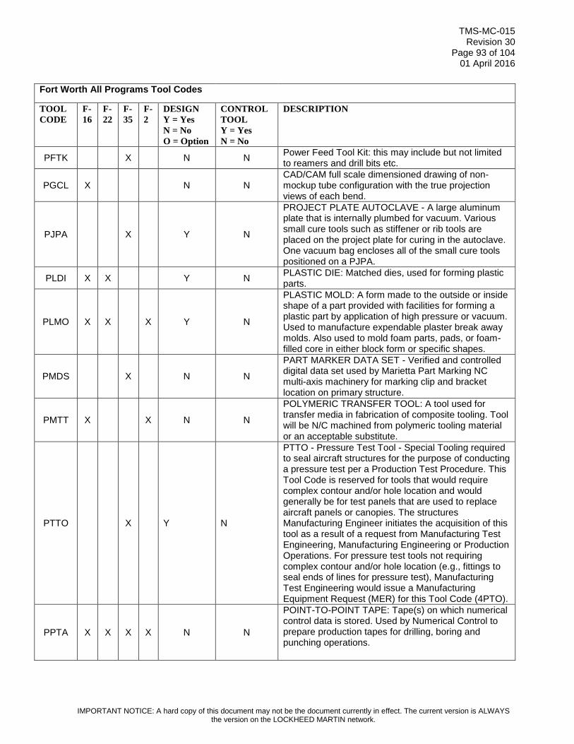
TMS-MC-015 Revision 30
Page 93 of 104 01 April 2016
IMPORTANT NOTICE: A hard copy of this document may not be the document currently in effect. The current version is ALWAYS the version on the LOCKHEED MARTIN network.
Fort Worth All Programs Tool Codes
TOOL
CODE
F-
16
F-
22
F-
35
F-
2
DESIGN
Y = Yes
N = No
O = Option
CONTROL
TOOL
Y = Yes
N = No
DESCRIPTION
PFTK X N N Power Feed Tool Kit: this may include but not limited to reamers and drill bits etc.
PGCL X N N CAD/CAM full scale dimensioned drawing of non-mockup tube configuration with the true projection views of each bend.
PJPA X Y N
PROJECT PLATE AUTOCLAVE - A large aluminum plate that is internally plumbed for vacuum. Various small cure tools such as stiffener or rib tools are placed on the project plate for curing in the autoclave. One vacuum bag encloses all of the small cure tools positioned on a PJPA.
PLDI X X Y N PLASTIC DIE: Matched dies, used for forming plastic parts.
PLMO X X X Y N
PLASTIC MOLD: A form made to the outside or inside shape of a part provided with facilities for forming a plastic part by application of high pressure or vacuum. Used to manufacture expendable plaster break away molds. Also used to mold foam parts, pads, or foam-filled core in either block form or specific shapes.
PMDS X N N
PART MARKER DATA SET - Verified and controlled digital data set used by Marietta Part Marking NC multi-axis machinery for marking clip and bracket location on primary structure.
PMTT X X N N
POLYMERIC TRANSFER TOOL: A tool used for transfer media in fabrication of composite tooling. Tool will be N/C machined from polymeric tooling material or an acceptable substitute.
PTTO X Y N
PTTO - Pressure Test Tool - Special Tooling required to seal aircraft structures for the purpose of conducting a pressure test per a Production Test Procedure. This Tool Code is reserved for tools that would require complex contour and/or hole location and would generally be for test panels that are used to replace aircraft panels or canopies. The structures Manufacturing Engineer initiates the acquisition of this tool as a result of a request from Manufacturing Test Engineering, Manufacturing Engineering or Production Operations. For pressure test tools not requiring complex contour and/or hole location (e.g., fittings to seal ends of lines for pressure test), Manufacturing Test Engineering would issue a Manufacturing Equipment Request (MER) for this Tool Code (4PTO).
PPTA X X X X N N
POINT-TO-POINT TAPE: Tape(s) on which numerical control data is stored. Used by Numerical Control to prepare production tapes for drilling, boring and punching operations.

TMS-MC-015 Revision 30
Page 94 of 104 01 April 2016
IMPORTANT NOTICE: A hard copy of this document may not be the document currently in effect. The current version is ALWAYS the version on the LOCKHEED MARTIN network.
Fort Worth All Programs Tool Codes
TOOL
CODE
F-
16
F-
22
F-
35
F-
2
DESIGN
Y = Yes
N = No
O = Option
CONTROL
TOOL
Y = Yes
N = No
DESCRIPTION
PRFX X X X Y N
PREFIT FIXTURE: A fixture used to prefit details of a bonded or brazed assembly, to assure proper relation of parts during bonding or brazing operations. May include provisions for tack welding or drilling for tack rivets.
PRTA X X X X N N
PROFILE TAPE: Tape(s) on which numerical control data is stored. Used by Numerical Control to prepare production tapes for 2 & 3 axis and surface milling operations.
PTFX X X X O N PLATING FIXTURE: A fixture in which parts are held during plating. Used for chrome, cadmium, etc. plating.
RATF X Y N
ROTATE ACCESS AND TRANSPORT FIXTURE - Used to hold assembly fixtures for moving from station to station as well as raise, lower and rotate for best ergonomic positioning.
RCCS X Y N RUBBER CAST CAUL SHEET - A cast or poured rubber sheet used as a caul sheet in composite fabrication.
RCTA X N N ROBOTIC COATING TAPE - NC Tape used to control the path of a robot to apply coatings of paint to aircraft components or structure.
REPD X X N N
REPRODUCTION: A full scale reproduction of engineering information, basic loft lines, master design layouts, etc. To be used only to identify reproduction of the above engineering information which is sent to vendors. DO NOT ASSIGN TOOL NUMBER.
RGTP X N N
ROUGH TEMPLATE: A flat piece of material, the perimeter of which shows the rough shape of a part with allowance for forming. May include provisions for drilling holes.
RPMT X X X X Y N
RAPID PROTOTYPE MULTI-USE TOOL: A tool is produced by the Fused Deposition Modeling (FDM) process. The tool is for locating and hand drilling hole patterns in detail parts, assemblies and sub-assys.
RSTP X O N RIVET SPRAY TEMPLATE: A thin metal or fiberglass template or shell used for spray marking rivet patterns.
RTCU X Y N ROUTER CUTTER: A high speed rotating tool used for removing material from a part.
RTFM X X N N
ROUTER FORM: A tool shaped to hold a part (or a stack of identical parts) and having contours or cutouts to act as a guide for the router cutter that is used to remove excess material.
RTFX X X X Y N
ROUTER FIXTURE: A tool used to locate and clamp assemblies in position while excess material is removed with a router. May also be used to perform drilling or other operations.

TMS-MC-015 Revision 30
Page 95 of 104 01 April 2016
IMPORTANT NOTICE: A hard copy of this document may not be the document currently in effect. The current version is ALWAYS the version on the LOCKHEED MARTIN network.
Fort Worth All Programs Tool Codes
TOOL
CODE
F-
16
F-
22
F-
35
F-
2
DESIGN
Y = Yes
N = No
O = Option
CONTROL
TOOL
Y = Yes
N = No
DESCRIPTION
RTSH X X X N N ROUTER SHELL: A shell similar to a TRSH except includes a surface which can be used as a router guide (3/8 inch or more in thickness).
RTTP X X N N
ROUTER TEMPLATE: A flat piece of material, the perimeter of which is the shape of the part. It is made undersize to allow for the router guide, except in areas which the part is not to be routed in which areas the template will be made the actual size of the part.
RVFX X Y N RIVET FIXTURE: A fixture to locate and hold parts in their relative position for riveting. Use for manual as well as automatic riveting.
SAFX X X O N
SAW FIXTURE: A fixture used to locate and clamp a part in position while cutting to size or removing excess material with a saw. May include a guide. Tool Design is required for F-35 Program.
SCTO X X O Y
SUPPLIER CONTROL TOOL: An SCTO is a reverse splash, made of fiberglass or plaster, made from MSCT. The SCTO will control all the part panel EOPs and other information that suppliers building purchased parts outside LM Aero facility may need.
SGDI X Y N
SWAGING DIE: A die consisting of a pair of steel blocks made smaller than a part in its original condition, which, by repeated blows reduce the part to the desired size and shape. If a forming mandrel (FMMD) is required, it should be given a separate tool number.
SMTO N N SHOP MADE TOOL: CANCELLED - DO NOT USE FOR NEW TOOLS EFFECTIVE SEPT. 1999
SPFD X O N
SUPER-PLASTIC FORM DIE: A tool used to form titanium or aluminum on a Super-Plastic Forming (SPF) press. The tool is made from high temperature ceramic and is cast from an N/C cut PMTT. Vendor dies may be made of steel. The tool and material are heated in the press prior to forming to allow super-plastic material deformation. Tool Design is required for F-35 Program.
SPMC X X Y N SPECIAL MACHINE: A device consisting of a power-supplying unit and accompanying details necessary to perform the required operations.
SPRM X X Y N
SPECIAL REAMER: A rotating tool, having a series of blades made of steel or harder material, used for enlarging a hole to achieve a close tolerance and/or finish.
SRVB X X X N N
Silicone Rubber Vacuum Bag: A Conformal Silicone Rubber Bag for use in Autoclave Cures and Debulking. Engineering Part Number to be Parent Tool Code and Number.

TMS-MC-015 Revision 30
Page 96 of 104 01 April 2016
IMPORTANT NOTICE: A hard copy of this document may not be the document currently in effect. The current version is ALWAYS the version on the LOCKHEED MARTIN network.
Fort Worth All Programs Tool Codes
TOOL
CODE
F-
16
F-
22
F-
35
F-
2
DESIGN
Y = Yes
N = No
O = Option
CONTROL
TOOL
Y = Yes
N = No
DESCRIPTION
SSCU X X T N SPOTFACING CUTTER: A cutting tool with radial blades, used for finishing a surface perpendicular to the centerline of a hole.
STBK X O N STRETCHER BLOCK: A stretcher block is a form made of plate stock around which a part is stretched to form simple or varying degree contours.
STDI X O N
STRETCHER DIE: A matched two piece die with opened ends for forming shapes in extrusions and sheet metal cross sections by pulling the part by each end until material reaches a plastic state and held until die is closed. STDIs are made of steel and using guide pins require a Tool Design Drawing.
STDW X O N
STRETCH DRAW: A matched die made of kirksite with or without plastic faced punch and/or die. Used to form sheet stock by stretching to a plastic state and then die forming.
STFM X X O N STRETCHER FORM: A stretcher form is a cast form over which a sheet of material or part is stretched to form compound or varying degree contours.
STJW X Y N STRETCHER JAWS: A set of blocks or jaws used for holding or clamping a part with a non-standard cross section while it is being stretched, formed or drawn.
SWFX X O N SPOTWELD FIXTURE: A fixture used to locate and clamp parts and/or assemblies in their relative position while performing spot weld operations.
SUPL X X X X O N
Supplemental/SUPL Tool - Tool Order issued by manufacturing Planners to support Production activity as relates to Quality Assurance Reports (QARs), (F35) Advanced Engineering Authorization (AEAs) Temporary Deviation Authorizations (TDAs) and Work-Arounds (WAPAs). The overall process refer to PM9003 20.19 Supplemental & Manufacturing Assist Tool Orders.
TFC@ X Y N
TRIM FIXTURE, CLAMP ASSISTED - Fixture in which parts are located and secured for NC trimming and drilling. A metal tool with mechanical clamping provisions for holding of part. The @ indicator is a placeholder for the letters "M" through "X" (NOTE: Complexity Codes M Thru X are FWT) which provide a twelve point value system as defined by the JSF Tool Code Size and Complexity Table.
TFCA X Y N
TRIM TOOL: Tool made of aluminum, designed to be used on a multi axis machine. This tool is typically used to trim small composite parts with simple flanges, channels or straps that can be held in place with clamps.

TMS-MC-015 Revision 30
Page 97 of 104 01 April 2016
IMPORTANT NOTICE: A hard copy of this document may not be the document currently in effect. The current version is ALWAYS the version on the LOCKHEED MARTIN network.
Fort Worth All Programs Tool Codes
TOOL
CODE
F-
16
F-
22
F-
35
F-
2
DESIGN
Y = Yes
N = No
O = Option
CONTROL
TOOL
Y = Yes
N = No
DESCRIPTION
TFV@ X Y N
TRIM FIXTURE, VACUUM ASSISTED - Fixture in which parts are located and secured for NC trimming and drilling. A metal tool plumbed for vacuum assisted holding of part. The @ indicator is a placeholder for the letters "E" through "L" and "M" through "X" (NOTE: Complexity Codes M Thru X are FWT) which provide a twelve point value system as defined by the JSF Tool Code Size and Complexity Table.
TFVA X Y N
TRIM FIXTURE: Tool made of aluminum, designed to be used on a multi-axis machine. This tool will include a vacuum system to hold the part in place; used to trim small to medium sized flat composite parts.
TFVB X Y N
TRIM FIXTURE: Tool made of aluminum, designed to be used on a multi-axis machine. This tool will include a vacuum system to hold the part in place; used to trim small to medium sized contoured parts.
TFVC X Y N
TRIM FIXTURE: Tool made of aluminum, designed to be used on a multi-axis machine. This tool will include a vacuum system to hold the part in place. This tool will be used to trim large F/A-22 contoured parts.
TFVD X Y N TRIM FIXTURE VACUUM ASSISTED: A vacuum assisted Trim Fixture used for N/C trimming and/or drilling of composite parts.
TFVE X Y N
TRIM FIXTURE, VACUUM ASSISTED: After and assembly is bonded together, the net trim and attached hole patterns and sometimes part contour need to be machined into the bond assembly. A Trim Fixture, Vacuum Assisted tool has various levels of complexity as noted by the last letter used in the tool code.
TFVF X Y N
TRIM FIXTURE, VACUUM ASSISTED: After and assembly is bonded together, the net trim and attached hole patterns and sometimes part contour need to be machined into the bond assembly. A Trim Fixture, Vacuum Assisted tool has various levels of complexity as noted by the last letter used in the tool code.
TFVG X Y N
TRIM FIXTURE, VACUUM ASSISTED: After and assembly is bonded together, the net trim and attached hole patterns and sometimes part contour need to be machined into the bond assembly. A Trim Fixture, Vacuum Assisted tool has various levels of complexity as noted by the last letter used in the tool code.
TFVH X Y N
TRIM FIXTURE, VACUUM ASSISTED: After and assembly is bonded together, the net trim and attached hole patterns and sometimes part contour need to be machined into the bond assembly. A Trim

TMS-MC-015 Revision 30
Page 98 of 104 01 April 2016
IMPORTANT NOTICE: A hard copy of this document may not be the document currently in effect. The current version is ALWAYS the version on the LOCKHEED MARTIN network.
Fort Worth All Programs Tool Codes
TOOL
CODE
F-
16
F-
22
F-
35
F-
2
DESIGN
Y = Yes
N = No
O = Option
CONTROL
TOOL
Y = Yes
N = No
DESCRIPTION
Fixture, Vacuum Assisted tool has various levels of complexity as noted by the last letter used in the tool code.
TFVI X Y N
TRIM FIXTURE, VACUUM ASSISTED: After and assembly is bonded together, the net trim and attached hole patterns and sometimes part contour need to be machined into the bond assembly. A Trim Fixture, Vacuum Assisted tool has various levels of complexity as noted by the last letter used in the tool code.
TFVJ X Y N
TRIM FIXTURE, VACUUM ASSISTED: After and assembly is bonded together, the net trim and attached hole patterns and sometimes part contour need to be machined into the bond assembly. A Trim Fixture, Vacuum Assisted tool has various levels of complexity as noted by the last letter used in the tool code.
TFVK X Y N
TRIM FIXTURE, VACUUM ASSISTED: After and assembly is bonded together, the net trim and attached hole patterns and sometimes part contour need to be machined into the bond assembly. A Trim Fixture, Vacuum Assisted tool has various levels of complexity as noted by the last letter used in the tool code.
TFVL X Y N
TRIM FIXTURE, VACUUM ASSISTED: After and assembly is bonded together, the net trim and attached hole patterns and sometimes part contour need to be machined into the bond assembly. A Trim Fixture, Vacuum Assisted tool has various levels of complexity as noted by the last letter used in the tool code.
TFVM X Y N
A TRIM FIXTURE, VACUUM ASSISTED made of aluminum for the use on the Flexible Overhead Gantry (FOG). This tool is used to trim the EOPs and IML surface and drill fastener holes in parts with planar or very mild (less than 1 in. deep) contour that are less than 3 ft. in length or width. For F-35: tool dimensions = < 1 M; size = small; complexity = simple (planar or very mild contour).
TFVN X Y N
A TRIM FIXTURE, VACUUM ASSISTED made of aluminum for the use on the Flexible Overhead Gantry (FOG). This tool is used to trim the EOPs and IML surface and drill fastener holes in parts with short 90 degree or open angle flange or moderate (greater than 1 in. and less than 2 in. deep) contour that is less than 3 ft. in length or width. For F-35: tool dimensions = < 1 M; size = small; complexity = moderate (parts with a 90° or open angle flange or medium contour).

TMS-MC-015 Revision 30
Page 99 of 104 01 April 2016
IMPORTANT NOTICE: A hard copy of this document may not be the document currently in effect. The current version is ALWAYS the version on the LOCKHEED MARTIN network.
Fort Worth All Programs Tool Codes
TOOL
CODE
F-
16
F-
22
F-
35
F-
2
DESIGN
Y = Yes
N = No
O = Option
CONTROL
TOOL
Y = Yes
N = No
DESCRIPTION
TFVO X Y N
A TRIM FIXTURE, VACUUM ASSISTED made of aluminum for the use on the Flexible Overhead Gantry (FOG). This tool is used to trim the EOPs and IML surface and drill fastener holes in parts with a closed angle flange, double “C”, or complex (greater than 2 in. deep) contour that is less than 3 ft. in length or width. For F-35: tool dimensions = < 1 M; size = small; complexity = complex (parts with a closed angle flange, complex contour, or requiring segmented details).
TFVP X Y N
A TRIM FIXTURE, VACUUM ASSISTED made of aluminum for the use on the Flexible Overhead Gantry (FOG). This tool is used to trim the EOPs and IML surface and drill fastener holes in parts with planar or very mild (less than 3 in. deep) contour that are greater than 3 ft., but less than 9 ft. in length or width. For F-35: tool dimensions = > 1 M & < 3 M; size = medium; complexity = simple (planar or very mild contour).
TFVQ X Y N
A TRIM FIXTURE, VACUUM ASSISTED made of aluminum or fiberglass with an eggcrate understructure for the use on the Flexible Overhead Gantry (FOG). This tool is used to trim the EOPs and IML surface and drill fastener holes in parts with long 90 degree or open angle flange or moderate (greater than 3 in. and less than 6 in. deep) contour that is less than 3 ft. but less than 9 ft. in length or width. For F-35: tool dimensions = < 1 M & < 3 M; size = small; complexity = moderate (parts with a 90° or open angle flange or medium contour).
TFVR X Y N
A TRIM FIXTURE, VACUUM ASSISTED made of aluminum or fiberglass for use on the Flexible Overhead Gantry (FOG). This tool is used to trim the EOPs and IML surface and drill fastener holes in parts with a closed angle flange, double “C” flange, or complex (greater than 6 in. deep) contour that are greater than 3 ft. but less than 9 ft. in length or width. For F-35: tool dimensions = > 1 M & < 3 M; size = medium; complexity = complex (parts with a closed angle flange, complex contour, or requiring segmented details).
TFVS X Y N
A TRIM FIXTURE, VACUUM ASSISTED made of aluminum or fiberglass for use on the Flexible Overhead Gantry (FOG). This tool is used to trim the EOPs and IML surface and drill fastener holes in parts with planar or very mild (less than 4 in. deep) contour that are greater than 9 ft. but less than 30 ft. in length or width. For F-35: tool dimensions = > 3M & < 10 M;
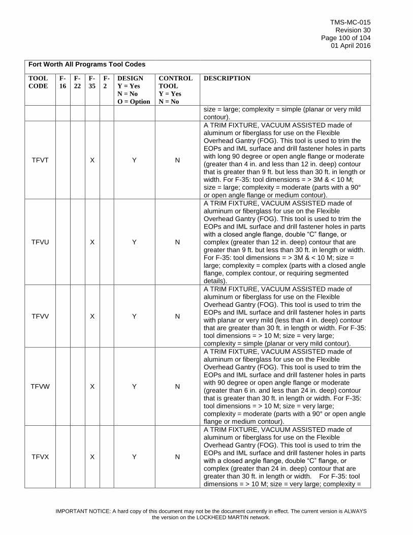
TMS-MC-015 Revision 30
Page 100 of 104 01 April 2016
IMPORTANT NOTICE: A hard copy of this document may not be the document currently in effect. The current version is ALWAYS the version on the LOCKHEED MARTIN network.
Fort Worth All Programs Tool Codes
TOOL
CODE
F-
16
F-
22
F-
35
F-
2
DESIGN
Y = Yes
N = No
O = Option
CONTROL
TOOL
Y = Yes
N = No
DESCRIPTION
size = large; complexity = simple (planar or very mild contour).
TFVT X Y N
A TRIM FIXTURE, VACUUM ASSISTED made of aluminum or fiberglass for use on the Flexible Overhead Gantry (FOG). This tool is used to trim the EOPs and IML surface and drill fastener holes in parts with long 90 degree or open angle flange or moderate (greater than 4 in. and less than 12 in. deep) contour that is greater than 9 ft. but less than 30 ft. in length or width. For F-35: tool dimensions = > 3M & < 10 M; size = large; complexity = moderate (parts with a 90° or open angle flange or medium contour).
TFVU X Y N
A TRIM FIXTURE, VACUUM ASSISTED made of aluminum or fiberglass for use on the Flexible Overhead Gantry (FOG). This tool is used to trim the EOPs and IML surface and drill fastener holes in parts with a closed angle flange, double “C” flange, or complex (greater than 12 in. deep) contour that are greater than 9 ft. but less than 30 ft. in length or width. For F-35: tool dimensions = > 3M & < 10 M; size = large; complexity = complex (parts with a closed angle flange, complex contour, or requiring segmented details).
TFVV X Y N
A TRIM FIXTURE, VACUUM ASSISTED made of aluminum or fiberglass for use on the Flexible Overhead Gantry (FOG). This tool is used to trim the EOPs and IML surface and drill fastener holes in parts with planar or very mild (less than 4 in. deep) contour that are greater than 30 ft. in length or width. For F-35: tool dimensions = > 10 M; size = very large; complexity = simple (planar or very mild contour).
TFVW X Y N
A TRIM FIXTURE, VACUUM ASSISTED made of aluminum or fiberglass for use on the Flexible Overhead Gantry (FOG). This tool is used to trim the EOPs and IML surface and drill fastener holes in parts with 90 degree or open angle flange or moderate (greater than 6 in. and less than 24 in. deep) contour that is greater than 30 ft. in length or width. For F-35: tool dimensions = > 10 M; size = very large; complexity = moderate (parts with a 90° or open angle flange or medium contour).
TFVX X Y N
A TRIM FIXTURE, VACUUM ASSISTED made of aluminum or fiberglass for use on the Flexible Overhead Gantry (FOG). This tool is used to trim the EOPs and IML surface and drill fastener holes in parts with a closed angle flange, double “C” flange, or complex (greater than 24 in. deep) contour that are greater than 30 ft. in length or width. For F-35: tool dimensions = > 10 M; size = very large; complexity =

TMS-MC-015 Revision 30
Page 101 of 104 01 April 2016
IMPORTANT NOTICE: A hard copy of this document may not be the document currently in effect. The current version is ALWAYS the version on the LOCKHEED MARTIN network.
Fort Worth All Programs Tool Codes
TOOL
CODE
F-
16
F-
22
F-
35
F-
2
DESIGN
Y = Yes
N = No
O = Option
CONTROL
TOOL
Y = Yes
N = No
DESCRIPTION
complex (parts with a closed angle flange, complex contour, or requiring segmented details).
THGA X X Y N THREAD GAGE: A gage used for checking pitch diameter, lead and/or thread form of internal or external threaded parts.
TLTP X X N N
TOOL LOCATING TEMPLATE: A template or a set of templates made of stable translucent material developed from a Manufacturing Engineering Tooling Model (METM). The tool will control fiber direction of the unidirectional tape, indexing provisions, and relate the plies laminates to each other and to common reference points.
TMFX X N N
TEMPORARY MOD FIXTURE: A non-designed, limited use tool manufactured from engineering data that will be used on a temporary basis to drill, locate or trim aircraft structure during non-production aircraft modifications. Requirements for the Temporary Mod Fixture (TMFX) will be determined by manufacturing engineering in order to support non- production Mod operations. TMFX tools will be utilized as a temporary solution to accomplish Mod assembly operations for a limited number of ship effectivities when permanent tooling is not available. Use of the TMFX is Limited to non-I-R applications. TMFX tools may be manufactured from any of the approved tooling materials listed in the PM-4053 Tooling Manual. If required, solid models must be vaulted in PDM. Tool Verification – dimensional verification by use of conventional measurement equipment. Trial Run required.
TOAC X X X X Y N TOOLING ACCESSORY: A tool made for use on or in conjunction with another tool.
TOFA X N Y
TOOLING FORM: An N/C machined Tooling Form constructed with modeling board (such as Ren 450). The tool is used for fabricating and inspecting various tools such as lay-up templates, flat pattern plies and production samples. A TOFA will be mounted on an aluminum plate base. Typically used for small to medium parts without significant contour.

TMS-MC-015 Revision 30
Page 102 of 104 01 April 2016
IMPORTANT NOTICE: A hard copy of this document may not be the document currently in effect. The current version is ALWAYS the version on the LOCKHEED MARTIN network.
Fort Worth All Programs Tool Codes
TOOL
CODE
F-
16
F-
22
F-
35
F-
2
DESIGN
Y = Yes
N = No
O = Option
CONTROL
TOOL
Y = Yes
N = No
DESCRIPTION
TOFB* X X N Y
TOOLING FORM: An N/C machined Tooling Form constructed with modeling board (such as Ren 450). The tool is used for fabricating and inspecting various tools such as lay-up templates, flat pattern plies and production samples. Construction of the tool may be hollow or solid. A TOFB will be mounted on a welded steel base. Typically used for medium to large parts or those parts having significant contour. *For F-35: Per F-35 Management direction, TOFB should not be ordered for I-R control effective T/V/Ship 2AF-0001 and on, for CTOL, 2BH-0001 and on for STOVL, and 2CF-0001 and on for CV. Use COMG in lieu of TOFB.
TOFM X X X N Y TOOLING FORM: A plaster, wood or fiberglass form made full size of an airplane part or assembly. Used for making and/or checking other tools.
TOGA X X X X Y Y TOOLING GAGE: A gage used by Tool Manufacturing Departments only for dimensional control of other tools.
TOMO X X X X O Y
TOOLING MOLD: Any permanent type mold required for repetitive molding of tooling materials into controlled shapes for use as tool details of a standard or peculiar design, of an expendable nature. It also may be used as a reference tool to produce other tools. Tool Design is required for F-35 Program.
TOPA X X N Y TOOLING PATTERN: A pattern used for casting purposes in making other tools. Pattern is made oversize to allow for shrinkage.
TOPE X X Y Y TOOLING PLATE: A tool used to accurately control a pattern of holes and line-of-sight. Used by Tool Manufacturing Department only.
TOSE X X X N Y TOOL SAMPLE: A complete or partial simulation of a part made to fit an assembly, used for fabrication or checking other tools.
TOTA X X X X N Y TOOLING TAPE: A tape on which data is stored for the operation of a machine. Used for the production to tooling details.
TOTP X X X O Y
TOOLING TEMPLATE: A flat piece of material that shows hole patterns, mold lines and other information by means of holes in the template or lines or markings on the face of the template. The perimeter is cut to the shape of the part and may be actual size of increased or diminished in scale. The template is used for fabrication and/or checking other tools.
TRDI X O N TRIM DIE: A punch and a die used for trimming a part after it is formed or for trimming the ends of a strip.
TRSH X X X N N
TRIM SHELL: A thin shell made to the exact size and shape of either the inside or outside of a part on which it fits. Used for marking, drilling, cutting or any combination of these operations on a part.

TMS-MC-015 Revision 30
Page 103 of 104 01 April 2016
IMPORTANT NOTICE: A hard copy of this document may not be the document currently in effect. The current version is ALWAYS the version on the LOCKHEED MARTIN network.
Fort Worth All Programs Tool Codes
TOOL
CODE
F-
16
F-
22
F-
35
F-
2
DESIGN
Y = Yes
N = No
O = Option
CONTROL
TOOL
Y = Yes
N = No
DESCRIPTION
TRTF X Y N
TURN AROUND TRANSPORT FIXTURE - A tool that indexes to and supports an aircraft component in order to remove the AJTF and present the second side of the component to the PMM or autodrill machines. The TRTF indexes to an HJTF.
TSTO X X Y N TESTING TOOL: A tool used to check a production part or assembly mechanically, electrically, hydraulically or pneumatically.
TTAC X X Y N
TEST TOOL ACCESSORIES: A tool used in conjunction with test equipment to assist the test equipment or make it adaptable to a number of parts, assemblies or systems. May involve mechanical, electronic, electrical, hydraulic or pneumatic principles.
TUCA X O N
TURNING CAM: A cam used on lathes, screw machines, etc., to control the position of the cutting tool or when used in a series to control the cycle of operations performed on a part.
TUFX X X Y N TURNING FIXTURE: A fixture used to locate and clamp a part in a position relative to a cutting tool while turning the part.
VCTO X X O Y
VENDOR CONTROL TOOL: A VCTO is a reverse splash made of fiberglass or plaster, made from a MSCT. The VCTO will control all the part panel EOPs and other information that suppliers building purchased parts outside LM-Aero facility may need.
VFBX X O N
VACUUM FORM BOX: A box for holding vacuum and/or air pressure to either vacuum draw or billow the heated sheet prior to contracting the sheet with a male VFMO. Must be made adaptable to the thermoplastic vacuum forming machine.
VFMO X O N
VACUUM FORM MOLD: A form made to the inside or outside of a thermoplastic part, provided with facilities for adaptation to the thermoplastic vacuum forming machine. Tool to have vacuum, air pressure, heating and cooling provisions as may be required.
VFPA X O N
VACUUM FORM PLUG ASSIST: A male type plug to pre-stretch the hot sheet of thermoplastic material, in a uniform manner, to approximate size, before vacuum is applied to the VFMO for final shape. Tool may require heating and cooling provisions as necessary.
VSJW X O N VISE JAWS: A set of shaped jaws or blocks mounted in a vise. Used for clamping or locating a part while performing the required operation(s).
WJFX X X Y N WATER JET FIXTURE - A fixture which holds the part in relation to the abrasive water jet for trimming operations.
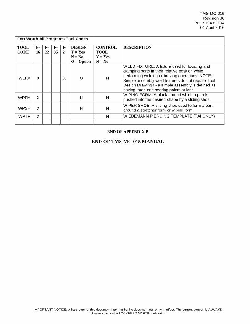
TMS-MC-015 Revision 30
Page 104 of 104 01 April 2016
IMPORTANT NOTICE: A hard copy of this document may not be the document currently in effect. The current version is ALWAYS the version on the LOCKHEED MARTIN network.
Fort Worth All Programs Tool Codes
TOOL
CODE
F-
16
F-
22
F-
35
F-
2
DESIGN
Y = Yes
N = No
O = Option
CONTROL
TOOL
Y = Yes
N = No
DESCRIPTION
WLFX X X O N
WELD FIXTURE: A fixture used for locating and clamping parts in their relative position while performing welding or brazing operations. NOTE: Simple assembly weld features do not require Tool Design Drawings - a simple assembly is defined as having three engineering points or less.
WPFM X N N WIPING FORM: A block around which a part is pushed into the desired shape by a sliding shoe.
WPSH X N N WIPER SHOE: A sliding shoe used to form a part around a stretcher form or wiping form.
WPTP X N WIEDEMANN PIERCING TEMPLATE (TAI ONLY)
END OF APPENDIX B
END OF TMS-MC-015 MANUAL