Embed Size (px)
Citation preview
SupplementaryMaterials
First-principlesstudyofcrystallographicslipmodesin𝝎-ZrAnilKumar1,M.ArulKumar2,andIreneJ.Beyerlein3
1TheoreticalDivision,LosAlamosNationalLaboratory,LosAlamos,NM87545
2MaterialsScienceandTechnologyDivision,LosAlamosNationalLaboratory,LosAlamos,NM87545
3MechanicalEngineeringDepartment,MaterialsDepartment,UniversityofCaliforniaatSantaBarbara,SantaBarbara,CA93106
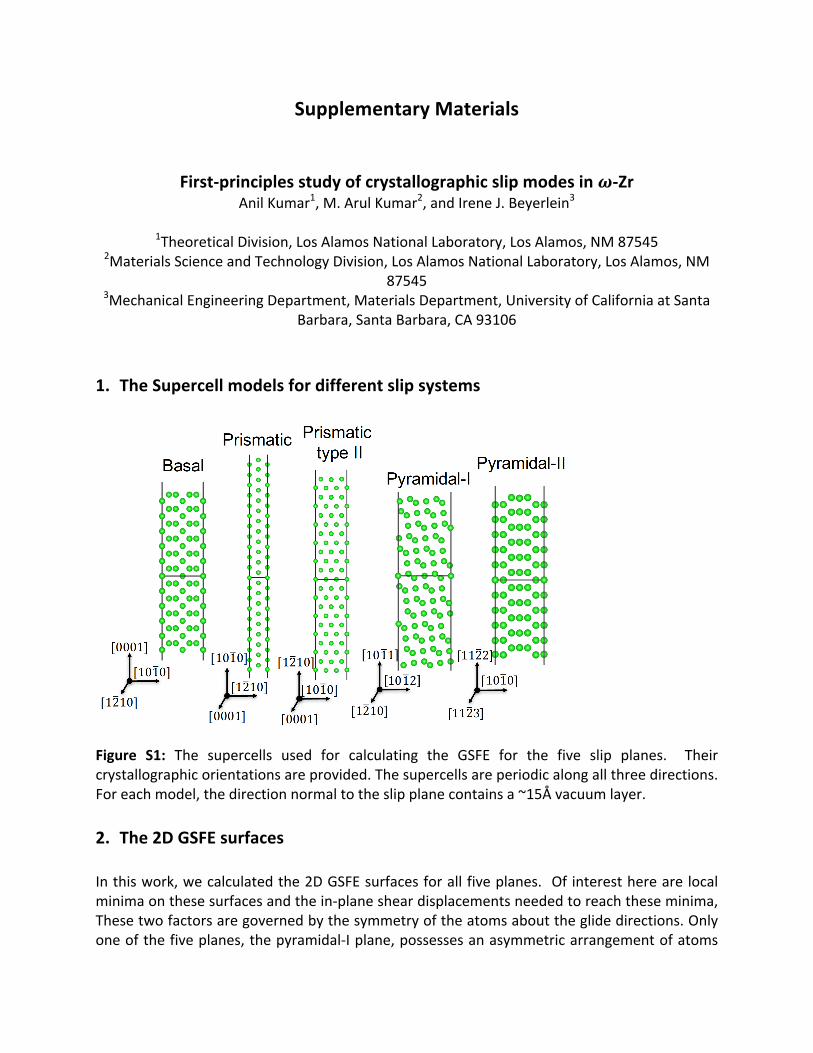
1. TheSupercellmodelsfordifferentslipsystems
Figure S1: The supercells used for calculating the GSFE for the five slip planes. Theircrystallographicorientationsareprovided.Thesupercellsareperiodicalongallthreedirections.Foreachmodel,thedirectionnormaltotheslipplanecontainsa~15Åvacuumlayer.2. The2DGSFEsurfacesInthiswork,wecalculatedthe2DGSFEsurfacesforallfiveplanes. Ofinterestherearelocalminimaonthesesurfacesandthein-planesheardisplacementsneededtoreachtheseminima,Thesetwofactorsaregovernedbythesymmetryoftheatomsabouttheglidedirections.Onlyoneofthefiveplanes,thepyramidal-Iplane,possessesanasymmetricarrangementofatoms
within the glide plane, and for this reason,we choose to include the full 2D surface for thisplaneinthemaintext.Fortheotherfourplanes,theatomicarrangementissymmetricalaboutthe theoretical shear direction and hence the low energy pathway corresponds to thetheoretical sheardirection. It, therefore, is sufficient toshow in themain text,only theGSFEcurve along this direction. However to be complete, in this supplement, in Figs. S2 and S3below,wepresentthe2Dsurfaceswecalculatedusingthesamemethodforthesefourplanes.
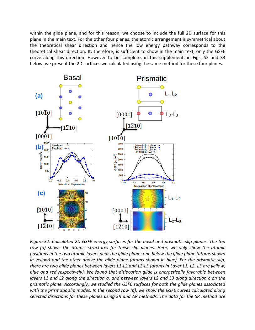
FigureS2:Calculated2DGSFEenergysurfacesforthebasalandprismaticslipplanes.Thetoprow (a) shows the atomic structures for these slip planes. Here, we only show the atomicpositionsinthetwoatomiclayersneartheglideplane:onebelowtheglideplane(atomsshownin yellow) and the other above the glide plane (atoms shown in blue). For the prismatic slip,therearetwoglideplanesbetweenlayersL1-L2andL2-L3[atomsinLayerL1,L2,L3areyellow,blueand red respectively].We found thatdislocationglide isenergetically favorablebetweenlayersL1andL2alongthedirectiona,andbetween layersL2andL3alongdirectioncontheprismaticplane.Accordingly,westudiedtheGSFEsurfacesforboththeglideplanesassociatedwiththeprismaticslipmodes.Inthesecondrow(b),weshowtheGSFEcurvescalculatedalongselecteddirectionsfortheseplanesusingSRandARmethods.ThedatafortheSRmethodare
shownbytheopensymbolsanddatafortheARmethodareshownbythefilledsymbols.Forthestructures, where the SR and the AR methods give the same GSFE, we only see the filledsymbols.Thethird-row(c)showsthe2DGSFEsurfacecalculatedusingDFTonagridforthetwoslipplanes.
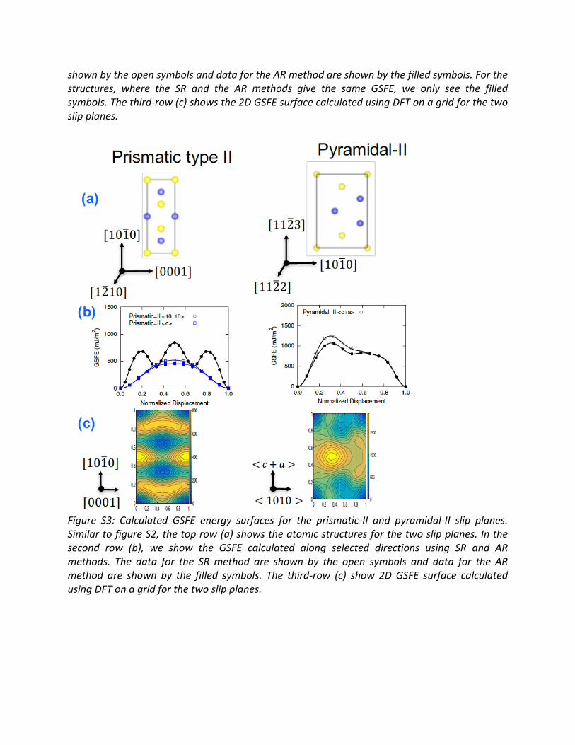
Figure S3: Calculated GSFE energy surfaces for the prismatic-II and pyramidal-II slip planes.SimilartofigureS2,thetoprow(a)showstheatomicstructuresforthetwoslipplanes.Inthesecond row (b), we show the GSFE calculated along selected directions using SR and ARmethods. The data for the SRmethod are shown by the open symbols and data for the ARmethod are shown by the filled symbols. The third-row (c) show 2D GSFE surface calculatedusingDFTonagridforthetwoslipplanes.
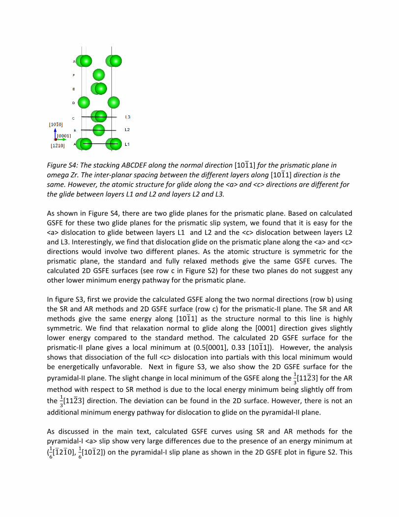
FigureS4:ThestackingABCDEFalongthenormaldirection[1011]fortheprismaticplaneinomegaZr.Theinter-planarspacingbetweenthedifferentlayersalong[1011]directionisthesame.However,theatomicstructureforglidealongthe<a>and<c>directionsaredifferentfortheglidebetweenlayersL1andL2andlayersL2andL3.AsshowninFigureS4,therearetwoglideplanesfortheprismaticplane.BasedoncalculatedGSFEforthesetwoglideplanesfortheprismaticslipsystem,wefoundthat it iseasyforthe<a>dislocation toglidebetween layersL1 andL2andthe<c>dislocationbetween layersL2andL3.Interestingly,wefindthatdislocationglideontheprismaticplanealongthe<a>and<c>directions would involve two different planes. As the atomic structure is symmetric for theprismatic plane, the standard and fully relaxed methods give the same GSFE curves. Thecalculated2DGSFEsurfaces(seerowc inFigureS2) forthesetwoplanesdonotsuggestanyotherlowerminimumenergypathwayfortheprismaticplane.InfigureS3,firstweprovidethecalculatedGSFEalongthetwonormaldirections(rowb)usingtheSRandARmethodsand2DGSFEsurface(rowc)fortheprismatic-IIplane.TheSRandARmethods give the same energy along [1011] as the structure normal to this line is highlysymmetric. We find that relaxation normal to glide along the [0001] direction gives slightlylower energy compared to the standard method. The calculated 2D GSFE surface for theprismatic-II plane gives a local minimum at (0.5[0001], 0.33 [1011]). However, the analysisshowsthatdissociationofthefull<c>dislocation intopartialswiththis localminimumwouldbe energetically unfavorable. Next in figure S3, we also show the 2D GSFE surface for thepyramidal-IIplane.TheslightchangeinlocalminimumoftheGSFEalongthe#
$[1123]fortheAR
methodwithrespecttoSRmethodisduetothelocalenergyminimumbeingslightlyofffromthe#
$[1123]direction.Thedeviationcanbefoundinthe2Dsurface.However,thereisnotan
additionalminimumenergypathwayfordislocationtoglideonthepyramidal-IIplane.As discussed in the main text, calculated GSFE curves using SR and AR methods for thepyramidal-I<a>slipshowverylargedifferencesduetothepresenceofanenergyminimumat(#'[1210],#
'[1012])onthepyramidal-Islipplaneasshowninthe2DGSFEplotinfigureS2.This
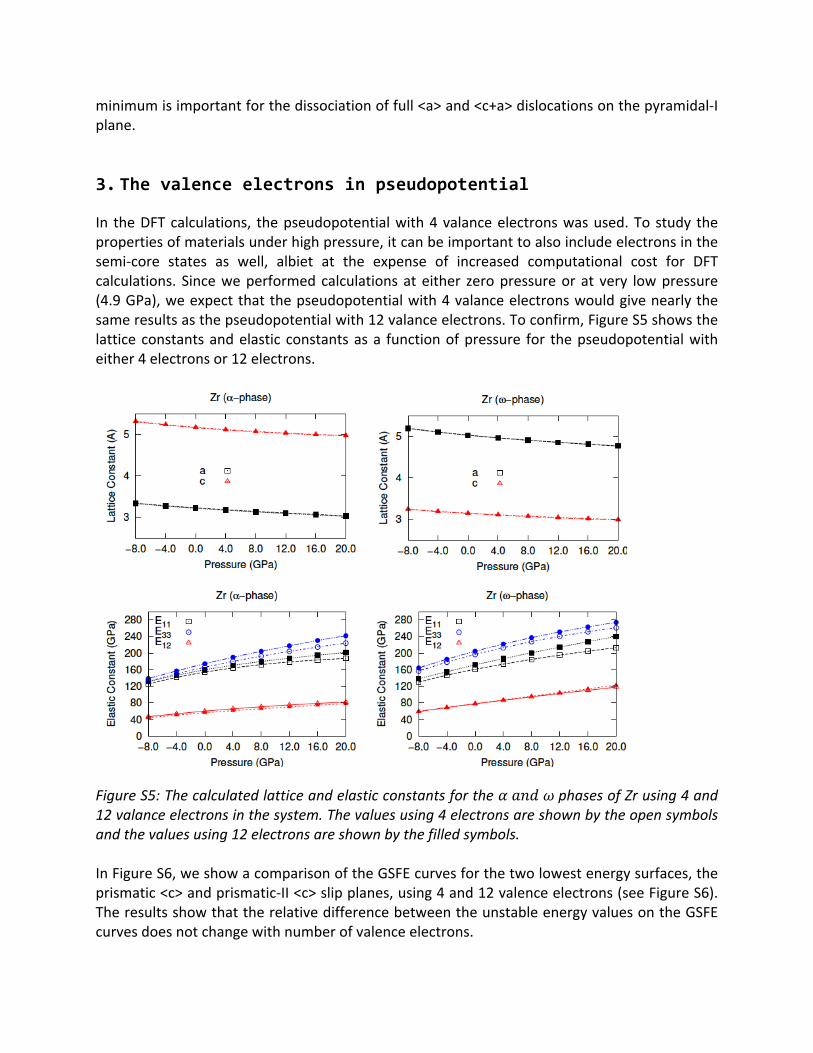
minimumisimportantforthedissociationoffull<a>and<c+a>dislocationsonthepyramidal-Iplane.3. The valence electrons in pseudopotential In theDFTcalculations, thepseudopotentialwith4valanceelectronswasused.Tostudy thepropertiesofmaterialsunderhighpressure,itcanbeimportanttoalsoincludeelectronsinthesemi-core states as well, albiet at the expense of increased computational cost for DFTcalculations. Sinceweperformedcalculationsateither zeropressureorat very lowpressure(4.9GPa),weexpectthatthepseudopotentialwith4valanceelectronswouldgivenearlythesameresultsasthepseudopotentialwith12valanceelectrons.Toconfirm,FigureS5showsthelatticeconstantsandelastic constantsasa functionofpressure for thepseudopotentialwitheither4electronsor12electrons.
FigureS5:Thecalculatedlatticeandelasticconstantsforthe𝛼𝑎𝑛𝑑𝜔phasesofZrusing4and12valanceelectronsinthesystem.Thevaluesusing4electronsareshownbytheopensymbolsandthevaluesusing12electronsareshownbythefilledsymbols.InFigureS6,weshowacomparisonoftheGSFEcurvesforthetwolowestenergysurfaces,theprismatic<c>andprismatic-II<c>slipplanes,using4and12valenceelectrons(seeFigureS6).TheresultsshowthattherelativedifferencebetweentheunstableenergyvaluesontheGSFEcurvesdoesnotchangewithnumberofvalenceelectrons.
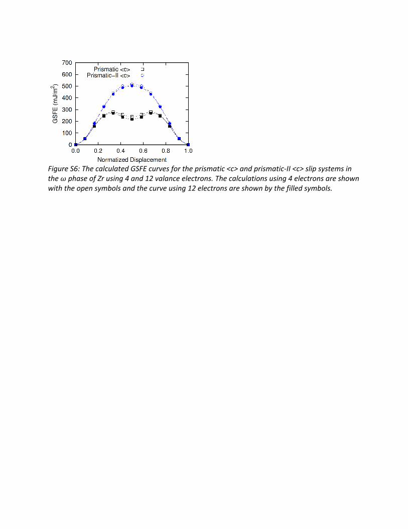
FigureS6:ThecalculatedGSFEcurvesfortheprismatic<c>andprismatic-II<c>slipsystemsinthe𝜔phaseofZrusing4and12valanceelectrons.Thecalculationsusing4electronsareshownwiththeopensymbolsandthecurveusing12electronsareshownbythefilledsymbols.