Embed Size (px)
Citation preview
robotics.sciencemag.org/cgi/content/full/4/36/eaay3493/DC1
Supplementary Materials for
Bioinspired dual-morphing stretchable origami
Woongbae Kim, Junghwan Byun, Jae-Kyeong Kim, Woo-Young Choi, Kirsten Jakobsen, Joachim Jakobsen,
Dae-Young Lee, Kyu-Jin Cho*
*Corresponding author. Email: [email protected]
Published 27 November 2019, Sci. Robot. 4, eaay3493 (2019)
DOI: 10.1126/scirobotics.aay3493
The PDF file includes:
Note S1. Dual morphing in nature Note S2. Design comparison between dual-morphing stretchable origami and conventional origami Note S3. Scaling relationship of dual-morphing stretchable origami Note S4. Parent origami frames and structural modification Note S5. Analytic evaluation of the deployment behavior of a Miura-ori polyhedron Note S6. Definition of the module, deployment ratio (λ), and angle (ϕ) of the dual-morphing M-ori Fig. S1. Layer molds and a stacking order for three different dual-morphing origami architectures. Fig. S2. Fabrication process of dual-morphing origami architectures: A layer stacking method. Fig. S3. Scaling relationship of dual-morphing stretchable origami. Fig. S4. Parent origami frames and arrangement of dual-morphing stretchable origami unit cells. Fig. S5. Kinematics of pelican eel and dual-morphing P-ori. Fig. S6. Comparison between conventional fluidic bending actuators and M-ori. Fig. S7. Parametric study of dual-morphing M-ori. Fig. S8. Geometry-dominant, origami-like morphing of dual-morphing M-ori with different α values. Fig. S9. Dynamic behavior of the two-module M-ori. Fig. S10. Strain-dominant soft robotic morphing of dual-morphing M-ori with programmed material disposition. Fig. S11. Deployment ratio (λ) and angle (ϕ) of dual-morphing M-ori. Fig. S12. Tip force of the six-module inner bending M-ori. Fig. S13. A dual-morphing M-ori gripper. Fig. S14. Architecture of material stiffness distribution in the soft robotic eye tentacle. Fig. S15. Dual-morphing Y-ori with programmability. Fig. S16. A dual-morphing human-interactive soft robot.
Other Supplementary Material for this manuscript includes the following: (available at robotics.sciencemag.org/cgi/content/full/4/36/eaay3493/DC1)
Movie S1 (.mp4 format). Dual-morphing behavior of a pelican eel. Movie S2 (.mp4 format). Pelican eel–like morphing of a stretchable origami fish base. Movie S3 (.mp4 format). Dual-morphing stretchable M-ori. Movie S4 (.mp4 format). Deployable soft gripper. Movie S5 (.mp4 format). Dual-morphing stretchable M-ori in the ground. Movie S6 (.mp4 format). Deployable soft crawler. Movie S7 (.mp4 format). Underwater soft tentacle. Movie S8 (.mp4 format). Dual-morphing stretchable Y-ori. Movie S9 (.mp4 format). Dual-morphing human-interactive soft robot for hugging. Movie S10 (.mp4 format). Dual-morphing stretchable Y-ori soft caging gripper. Movie S11 (.mp4 format). Layer mold stacking method.
Note S1. Dual morphing in nature
We define dual morphing as structurally embodied shape morphing driven by two different
principles. One principle is rotation, generally induced by folds, creases or joints, and the other is
the stretching of the skin and/or soft body. These two morphing modes usually appear to be
combined for the morphing of the entire body in a manner that lengthens it. Typical examples
include a skin that stretches with the help of embedded wrinkles and plant cells that grow via
both rotation and swelling (1).
On the other hand, for some dual-morphing systems found in nature, each morphing
mode takes different function. For example, the spreading tentacles of snail that roles as
olfactory epithelium use two different types of motion when morphing: (i) a local inverting
movement (twitching) for the removal of odor molecules or protection and (ii) a lateral
movement of extended tentacles (quivering) for expanding odor sense (3). Our recent
observation of pelican eel also shows that the morphing behavior of its inflating head is
characterized by two functionally decoupled modes, unfolding for spreading the mouth and
stretching for extreme volume increase, although no in-depth study has been conducted (23).
Note S2. Design comparison between dual-morphing stretchable origami and conventional
origami
Conventional origami consists of easily foldable crease lines with the connected rigid or
compliant facets (19-21). In general, the bending stiffness of the crease line is engineered to be
low enough to be negligible in comparison with the facets. Therefore, rotation occurs intensively
at the crease lines when the force is applied to the origami structure, resulting in easy folding or
unfolding. Previous approaches to design the low bending stiffness of the crease lines include the
use of mechanical hinges, embedment of flexible materials such as fabrics or films, and pre-
plastic deformation (e.g., paper folding).
In contrast, our dual-morphing origami is made entirely of soft and stretchable elastomers
and facets and crease lines are not distinguished by material stiffness. Because the bending
stiffness of both facets and crease lines are very low, facets as well as crease lines would easily
fold. Therefore, to create origami-like morphing of entire soft origami architecture, a new design
strategy that allows rotation to occur intensively at the crease line similar to the conventional
origami should be explored while the unique properties of elastomers (hyperelasticity, high
flexibility and stretchability) are also considered in design. Details on the design rule for dual-
morphing origami are as follows:
(i) A crease line of a dual-morphing origami unit cell is defined by a kinematically
arranged C-channel shaped geometry with the clamped facets (Fig. 1C). When fluid
pressure is applied, the direction of the pressure is distributed preferentially to create
rotational moment with respect to the clamped facets. As a result, the unfolding of the
dual-morphing origami unit cell, which is induced by the bending of the clamped facets,
takes precedence over the stretching (Fig. 1E).
(ii) In general, the crease line of conventional origami is designed as a very thin line, thus
its thickness (or width) and the corresponding rotational stiffness are considered to be
negligible. By contrast, that of dual-morphing origami should be designed to have a
sufficient width in order to withstand material stretching when morphing. Therefore, we
designed the crease line as a C-channel shaped deployable kinematic structure that has a
specific width (w), which also affects the rotational stiffness as discussed in the
manuscript and Fig. 4B.
(iii) In some cases, the folding of crease lines in conventional origami can be replaced with
the bending of flexible facets. Therefore, when designing dual-morphing origamis, it is
possible to combine multiple facets into a single facet by removing the crease lines that
do not affect the deployment behavior of the dual-morphing origami. In the case of
dual-morphing M-ori, for example, bending occurs around the center line of the concave
hexagon shaped facets, replacing the function of the original crease lines of the Miura-
ori polyhedron (fig. S4, C and D).
(iv) Due to the hyperelasticity of elastomers, it is impossible to fabricate dual-morphing
origami through pre-plastic deformation by folding. Different from conventional
origami that folds in the plane in order to create a three-dimensional structure, dual-
morphing origami architectures were fabricated by a ‘layer stacking method’ in which
dozens of flat layer molds were sequentially stacked together with the pouring of
elastomer (fig. S1 and S2).
(v) Elastomeric crease lines of dual-morphing origami have high elasticity. Thus, the
energy stored in the crease lines causes the restoring force to return to the initial state
when the applied external pressure is removed. The tendency of restoration becomes
larger as the width of the crease line, the thickness of the facets, and the stiffness of the
material increases.
(vi) Pneumatic actuation intrinsically requires the enclosure of the stretchable origami.
Origami geometries that can be easily (or by itself) enclosed such as cylindrical or
spherical (e.g. Yoshimura origami cylinder and origami magic ball) and double-layered
structures (e.g. Miura-ori polyhedron, double-layered origami fish base) are the
representative candidates of the allowable geometry. In addition, the pneumatic
actuation is proper for the fully folded geometry of origami in which volume increases
as unfolded. As a result, the initial state of dual-morphing origami was formed into a
fully folded geometry of parent origami.
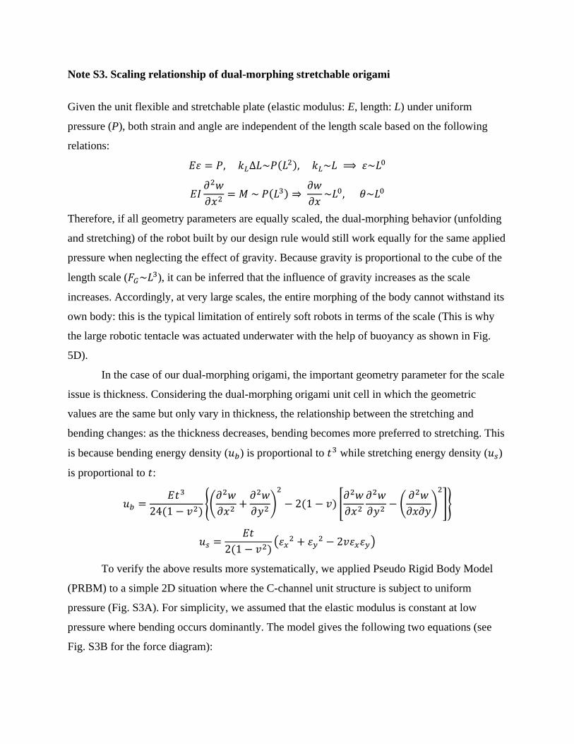
Note S3. Scaling relationship of dual-morphing stretchable origami
Given the unit flexible and stretchable plate (elastic modulus: E, length: L) under uniform
pressure (P), both strain and angle are independent of the length scale based on the following
relations:
𝐸𝜀 = 𝑃, 𝑘𝐿∆𝐿~𝑃(𝐿2), 𝑘𝐿~𝐿 ⟹ 𝜀~𝐿0
𝐸𝐼𝜕2𝑤
𝜕𝑥2= 𝑀 ~ 𝑃(𝐿3) ⇒
𝜕𝑤
𝜕𝑥~𝐿0, 𝜃~𝐿0
Therefore, if all geometry parameters are equally scaled, the dual-morphing behavior (unfolding
and stretching) of the robot built by our design rule would still work equally for the same applied
pressure when neglecting the effect of gravity. Because gravity is proportional to the cube of the
length scale (𝐹𝐺~𝐿3), it can be inferred that the influence of gravity increases as the scale
increases. Accordingly, at very large scales, the entire morphing of the body cannot withstand its
own body: this is the typical limitation of entirely soft robots in terms of the scale (This is why
the large robotic tentacle was actuated underwater with the help of buoyancy as shown in Fig.
5D).
In the case of our dual-morphing origami, the important geometry parameter for the scale
issue is thickness. Considering the dual-morphing origami unit cell in which the geometric
values are the same but only vary in thickness, the relationship between the stretching and
bending changes: as the thickness decreases, bending becomes more preferred to stretching. This
is because bending energy density (𝑢𝑏) is proportional to 𝑡3 while stretching energy density (𝑢𝑠)
is proportional to 𝑡:
𝑢𝑏 =𝐸𝑡3
24(1 − 𝑣2){(
𝜕2𝑤
𝜕𝑥2+
𝜕2𝑤
𝜕𝑦2)
2
− 2(1 − 𝑣) [𝜕2𝑤
𝜕𝑥2
𝜕2𝑤
𝜕𝑦2− (
𝜕2𝑤
𝜕𝑥𝜕𝑦)
2
]}
𝑢𝑠 =𝐸𝑡
2(1 − 𝑣2)(𝜀𝑥
2 + 𝜀𝑦2 − 2𝑣𝜀𝑥𝜀𝑦)
To verify the above results more systematically, we applied Pseudo Rigid Body Model
(PRBM) to a simple 2D situation where the C-channel unit structure is subject to uniform
pressure (Fig. S3A). For simplicity, we assumed that the elastic modulus is constant at low
pressure where bending occurs dominantly. The model gives the following two equations (see
Fig. S3B for the force diagram):
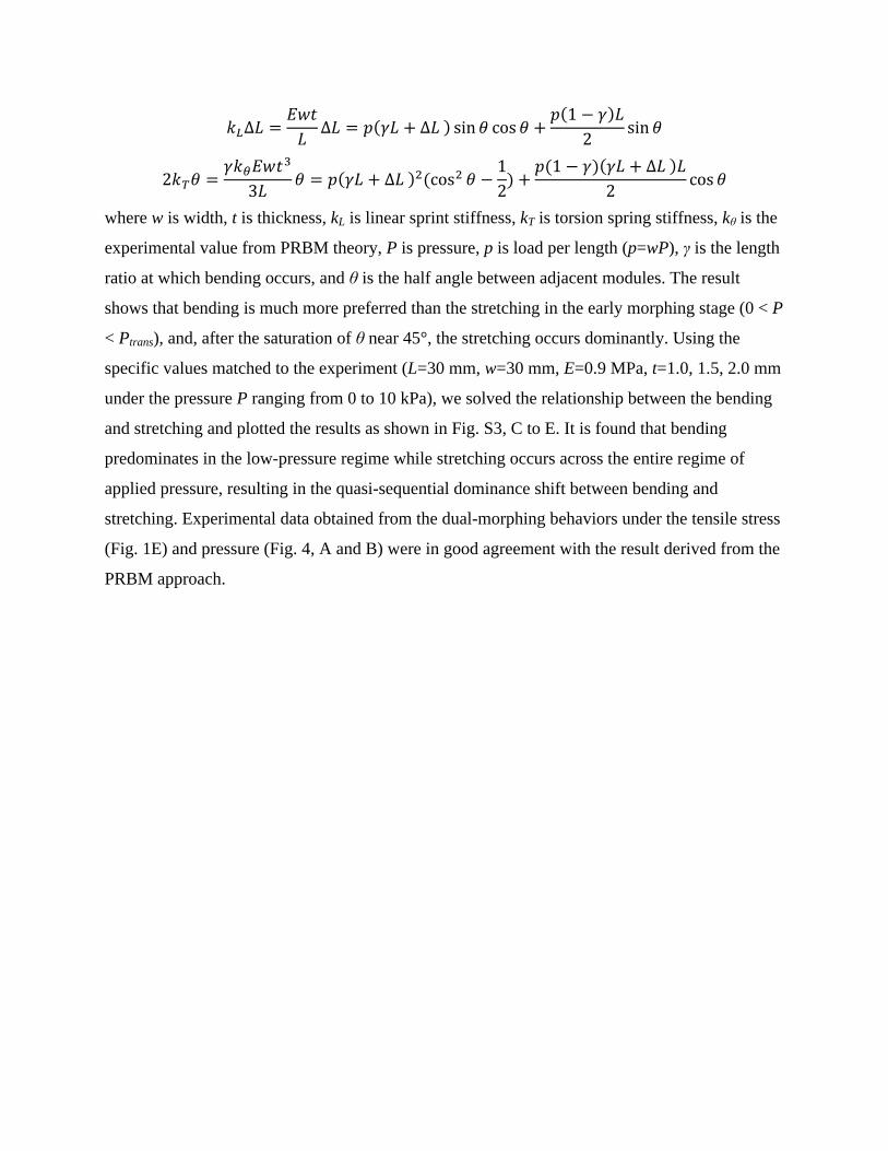
𝑘𝐿∆𝐿 =𝐸𝑤𝑡
𝐿∆𝐿 = 𝑝(𝛾𝐿 + ∆𝐿 ) sin 𝜃 cos 𝜃 +
𝑝(1 − 𝛾)𝐿
2sin 𝜃
2𝑘𝑇𝜃 =𝛾𝑘𝜃𝐸𝑤𝑡3
3𝐿𝜃 = 𝑝(𝛾𝐿 + ∆𝐿 )2(cos2 𝜃 −
1
2) +
𝑝(1 − 𝛾)(𝛾𝐿 + ∆𝐿 )𝐿
2cos 𝜃
where w is width, t is thickness, kL is linear sprint stiffness, kT is torsion spring stiffness, kθ is the
experimental value from PRBM theory, P is pressure, p is load per length (p=wP), γ is the length
ratio at which bending occurs, and θ is the half angle between adjacent modules. The result
shows that bending is much more preferred than the stretching in the early morphing stage (0 < P
< Ptrans), and, after the saturation of θ near 45°, the stretching occurs dominantly. Using the
specific values matched to the experiment (L=30 mm, w=30 mm, E=0.9 MPa, t=1.0, 1.5, 2.0 mm
under the pressure P ranging from 0 to 10 kPa), we solved the relationship between the bending
and stretching and plotted the results as shown in Fig. S3, C to E. It is found that bending
predominates in the low-pressure regime while stretching occurs across the entire regime of
applied pressure, resulting in the quasi-sequential dominance shift between bending and
stretching. Experimental data obtained from the dual-morphing behaviors under the tensile stress
(Fig. 1E) and pressure (Fig. 4, A and B) were in good agreement with the result derived from the
PRBM approach.
Note S4. Parent origami frames and structural modification
Origami fish base: A pelican eel origami architecture is the modified form of one of the most
classic origami patterns, ‘origami fish base’. The origami fish base is originally single-sheet-
foldable and generally used as a starting point for origami fish. By folding the reverse side of the
origami fish base backward along its center line, we built the shape of a pelican eel with a short
triangular mouth and a long triangular jaw (fig. S4A). When the mouth part of the origami
structure is pulled up and down, the entire structure unfolds and the facets spread sideways
similar to the geometric morphing of a natural pelican eel’s mouth in which the jaw spreads
sideways during its opening (Fig. 1A). By overlapping two origami fish layers, dual-morphing P-
ori with the skin (outer layer, highlighted in green in fig. S4B) and the frame (inner layer,
highlighted in blue in fig. S4B) was constructed. The skin layer was made of Ecoflex0010, while
the frame layer was made of Dragonskin30 with the additional rigid acrylic padding to prevent
buckling.
Miura origami: Miura origami is a tessellation comprised only of parallelograms that are
patterned in mirror symmetry (26). When two mirrored Miura origami with the same number of
parallelograms are connected along the boundary lines, a polyhedron-shaped origami structure is
constructed (fig. S4C). This Miura-ori polyhedron can be rigidly folded into the flat shape of the
stacked layers in which each of them consists of two parallelograms. Thus, the Miura-ori
polyhedron can be fully defined by three parameters of the parallelogram: the length of each side
(a and b) and the included angle (α) (fig. S4, C and D). Because of its asymmetric geometry
(connected in a zigzag shape), it is possible to make a large deployment ratio. By compositing
dual-morphing stretchable origami unit cells based on the Miura-ori polyhedron, we developed
dual-morphing M-ori. For fluidic actuation and desired dual-morphing behaviors, we modified
the Miura-ori polyhedron: A fold line shared by two parallelograms of the facet was removed in
order to avoid structural interference during the second strain-dominant morphing mode (fig.
S4C, a red dotted line in the inset image). The resulting design was a concave hexagon shaped
facet (fig. S4D). During the first origami-like morphing, the pre-removed crease line (centerline
of the hexagon shaped facet) behaved like a virtual crease line and therefore the facets bent
around this line. In addition, the diamond shaped crease lines at both ends of the dual-morphing
M-ori were enclosed by the plates with the same shape for sealing. In general, one of them was
bonded to the rigid surface to fix the dual-morphing M-ori.
Yoshimura origami: Yoshimura origami is a famous buckling pattern that appears when an axial
compression load is applied to a thin tube-shaped cylinder, in which triangles and inverted
triangles are connected continuously (27). The structure is not rigidly foldable, but can be
compressed into the flat shape when made of compliant materials (e.g. paper, fabric). When
folded, the structure, from the top view, is shaped into a polygon surrounded by triangles. The
cylinder is radially symmetric, so that its deployment is characterized by linear motion in the
height direction. Also, the triangle tessellation can be modified to the trapezoid tessellation (also
known as an accordion pattern or a bellows pattern), which is relatively more foldable than the
original one (fig. S4E). When all isosceles trapezoid tessellations are designed to be equal, the
structure can be fully defined by the length of the upper (c) and lower sides (d) of the isosceles
trapezoid and its angle (β). β is determined by the number of facets (n) that lie in the same plane
when fully folded.
𝛽 =90°
𝑛
For n=2 as shown in figure S4C, β has a value of 45°. The difference between the parent
Yoshimura origami cylinder and dual-morphing Y-ori is the width (w) and flat plates that were
attached at both the top and bottom place for fluidic actuation (fig. S4F).
Note S5. Analytic evaluation of the deployment behavior of a Miura-ori polyhedron
A Miura-ori polyhedron deploys in a way that maximizes its internal volume. A 1-module
Miura-ori polyhedron is composed of parallelograms with side lengths of a and b and the
subtended angle (α). Let ψ is a half of the included angle of two sides (length a) of different
parallelograms that contact in another side (length b) (fig. S8A). The inner volume of the 1-
module Miura-ori polyhedron (V) is represented as follows:
𝑉 = 2𝑎2𝑏 𝑠𝑖𝑛 𝜓 √𝑐𝑜𝑠2 𝜓 − 𝑐𝑜𝑠2 𝛼
We can find ψ that maximizes V by differentiating V with ψ
𝑑𝑉
𝑑𝜓= 2𝑎2𝑏
𝑐𝑜𝑠 𝜓
√𝑐𝑜𝑠2 𝜓 − 𝑐𝑜𝑠2 𝛼(2 𝑐𝑜𝑠2 𝜓 − 𝑐𝑜𝑠2 𝛼 − 1) = 0
cos 𝜓 =√2 + 2cos2 𝛼
2
When the included angle between the side (length b) and a line that equally divides two sides
(length a) is defined as 𝜃1𝑚𝑜𝑑𝑢𝑙𝑒, the following condition is satisfied.
cos 𝜃1𝑚𝑜𝑑𝑢𝑙𝑒 =cos 𝛼
cos 𝜓
𝜃1𝑚𝑜𝑑𝑢𝑙𝑒 = cos−1(2 cos 𝛼
√2 + 2cos2(𝛼))
Finally, the angle between the adjacent modules (θ) can be derived as:
𝜃 = 2𝜃1𝑚𝑜𝑑𝑢𝑙𝑒
𝜃 = 2 cos−1(2 cos 𝛼
√2 + 2cos2(𝛼))
From the equation, it is noted that the deployment behavior of a Miura-ori polyhedron
characterized by θ is defined only by the geometric parameter α (fig. S8B), and experimental
demonstration of dual-morphing M-ori with different α values (50, 65, 80°) verifies this
relationship (Fig. 4A and fig. S8C).
Note S6. Definition of the module, deployment ratio (λ), and angle (ϕ) of the dual-morphing
M-ori
We defined a unit module of dual-morphing M-ori as the structure consisting of a flat hexagon
shaped air chamber enclosed by two parallel facets. Multiple modules can be connected via a
diamond-shaped end loop of crease lines, so that a multi-module dual-morphing M-ori can be
easily formed by stacking (figs. S1 and S2). To define the deployment ratio (λ) and angle (ϕ) of
the dual-morphing M-ori, we expressed the module as a tetragon where its vertexes are located at
the joints of the fluidic channel from a cross-section view (fig. S11A). The center of each
module, ground, and ceiling are connected in straight segments, and the total length of the line is
defined as a length of the robot (L). According to the definition, the initial length (L0) is the
shortest length from the bottom to top of dual-morphing M-origami, and λ is defined as follows:
𝜆 =𝐿
𝐿0
To define the deployment angle (ϕ), two points are selected; one from the top facet and
the other from the bottom facet of the dual-morphing M-ori (fig. S11B). The point at the top
facet is the vertex of hexagon that is farthest from the adjacent air channel, which is the end-
point of the dual-morphing M-origami. Another point is a corresponding vertex at the bottom
facet. The deployment angle (ϕ) is defined as the angle between z-axis and the connected line of
the two points, and therefore, according to the definition, the initial deployment angle (ϕ0) is 0°.
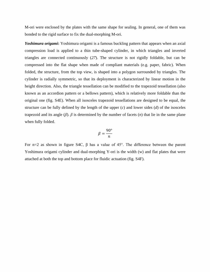
Fig. S1. Layer molds and a stacking order for three different dual-morphing origami
architectures. (A and B) Dual-morphing P-ori. (C and D) Dual-morphing M-ori. (E and F)
Dual-morphing Y-ori.
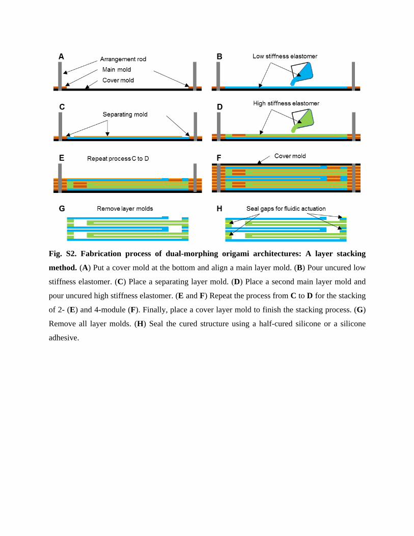
Fig. S2. Fabrication process of dual-morphing origami architectures: A layer stacking
method. (A) Put a cover mold at the bottom and align a main layer mold. (B) Pour uncured low
stiffness elastomer. (C) Place a separating layer mold. (D) Place a second main layer mold and
pour uncured high stiffness elastomer. (E and F) Repeat the process from C to D for the stacking
of 2- (E) and 4-module (F). Finally, place a cover layer mold to finish the stacking process. (G)
Remove all layer molds. (H) Seal the cured structure using a half-cured silicone or a silicone
adhesive.
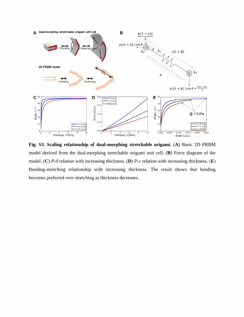
Fig. S3. Scaling relationship of dual-morphing stretchable origami. (A) Basic 2D PRBM
model derived from the dual-morphing stretchable origami unit cell. (B) Force diagram of the
model. (C) P-θ relation with increasing thickness. (D) P-ε relation with increasing thickness. (E)
Bending-stretching relationship with increasing thickness. The result shows that bending
becomes preferred over stretching as thickness decreases.
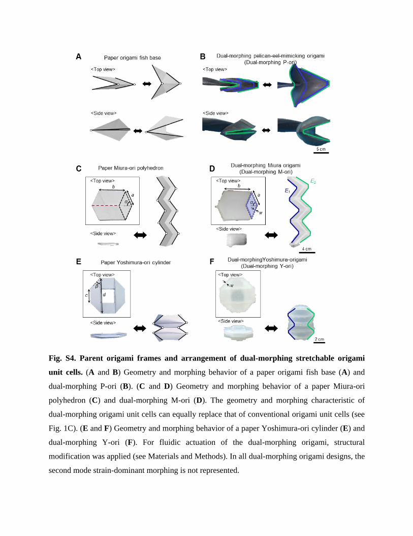
Fig. S4. Parent origami frames and arrangement of dual-morphing stretchable origami
unit cells. (A and B) Geometry and morphing behavior of a paper origami fish base (A) and
dual-morphing P-ori (B). (C and D) Geometry and morphing behavior of a paper Miura-ori
polyhedron (C) and dual-morphing M-ori (D). The geometry and morphing characteristic of
dual-morphing origami unit cells can equally replace that of conventional origami unit cells (see
Fig. 1C). (E and F) Geometry and morphing behavior of a paper Yoshimura-ori cylinder (E) and
dual-morphing Y-ori (F). For fluidic actuation of the dual-morphing origami, structural
modification was applied (see Materials and Methods). In all dual-morphing origami designs, the
second mode strain-dominant morphing is not represented.
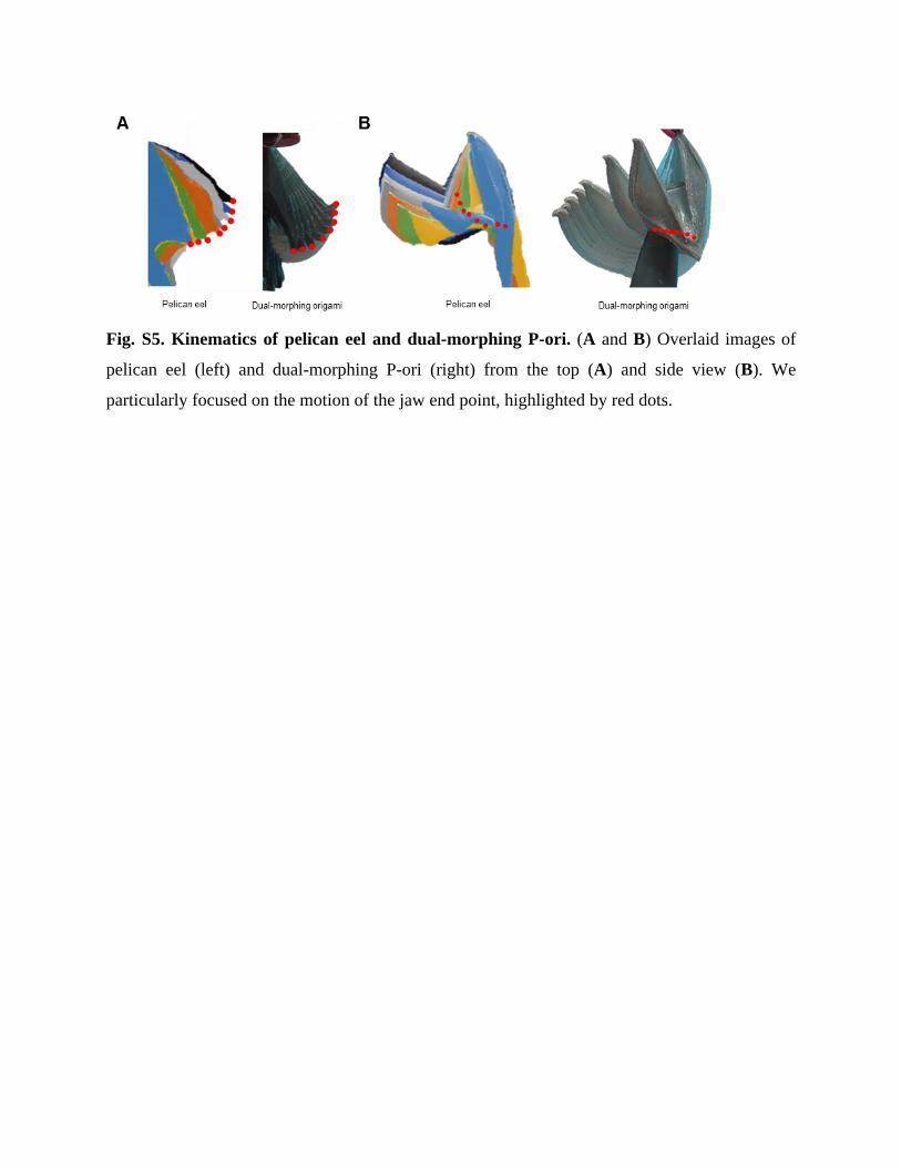
Fig. S5. Kinematics of pelican eel and dual-morphing P-ori. (A and B) Overlaid images of
pelican eel (left) and dual-morphing P-ori (right) from the top (A) and side view (B). We
particularly focused on the motion of the jaw end point, highlighted by red dots.
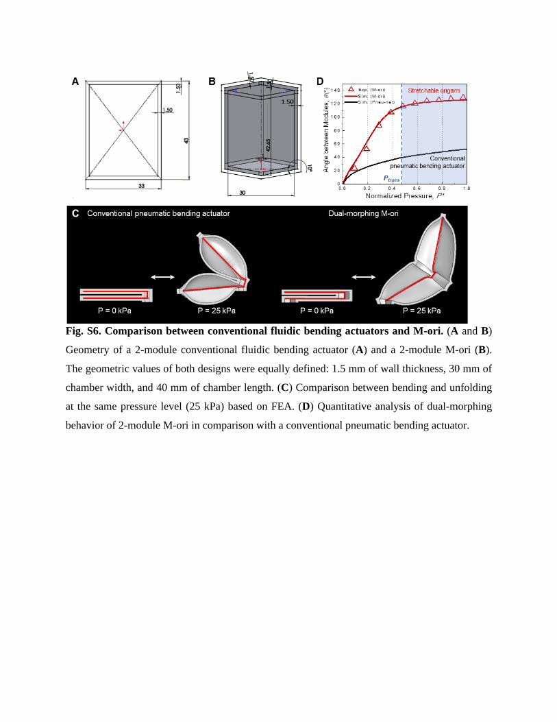
Fig. S6. Comparison between conventional fluidic bending actuators and M-ori. (A and B)
Geometry of a 2-module conventional fluidic bending actuator (A) and a 2-module M-ori (B).
The geometric values of both designs were equally defined: 1.5 mm of wall thickness, 30 mm of
chamber width, and 40 mm of chamber length. (C) Comparison between bending and unfolding
at the same pressure level (25 kPa) based on FEA. (D) Quantitative analysis of dual-morphing
behavior of 2-module M-ori in comparison with a conventional pneumatic bending actuator.
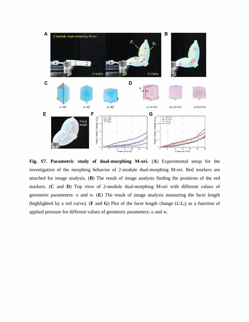
Fig. S7. Parametric study of dual-morphing M-ori. (A) Experimental setup for the
investigation of the morphing behavior of 2-module dual-morphing M-ori. Red markers are
attached for image analysis. (B) The result of image analysis finding the positions of the red
markers. (C and D) Top view of 2-module dual-morphing M-ori with different values of
geometric parameters: α and w. (E) The result of image analysis measuring the facet length
(highlighted by a red curve). (F and G) Plot of the facet length change (L/L0) as a function of
applied pressure for different values of geometric parameters: α and w.
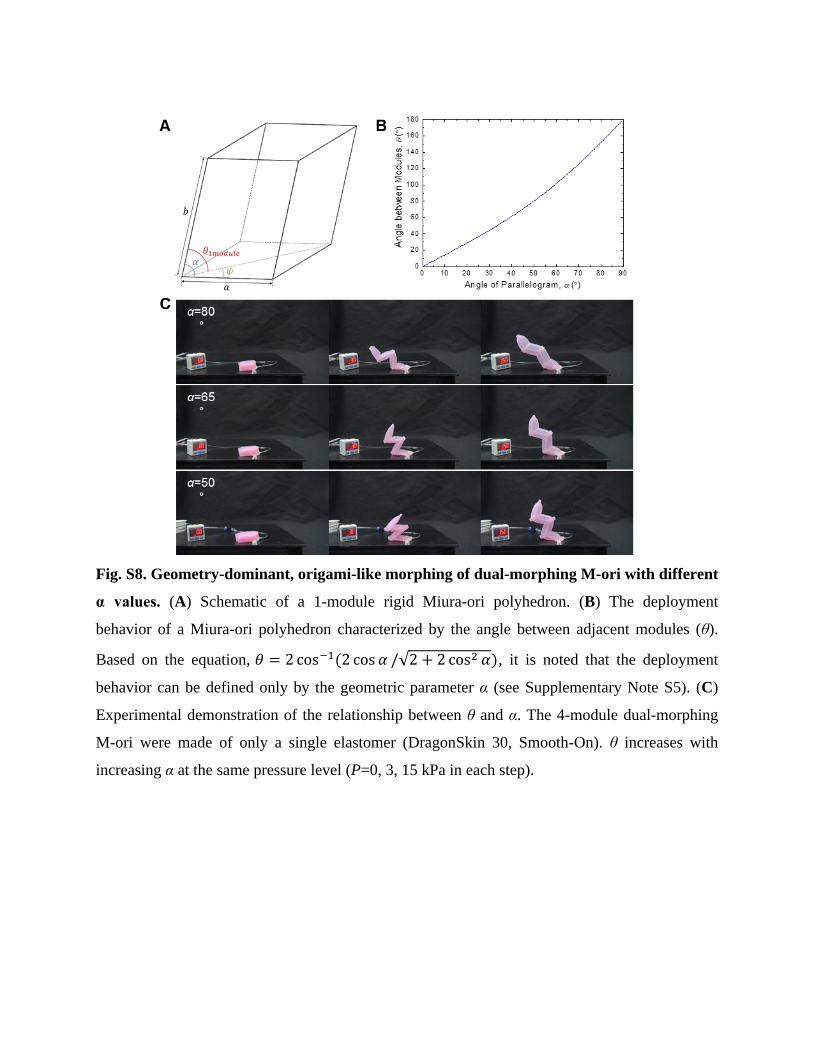
Fig. S8. Geometry-dominant, origami-like morphing of dual-morphing M-ori with different
α values. (A) Schematic of a 1-module rigid Miura-ori polyhedron. (B) The deployment
behavior of a Miura-ori polyhedron characterized by the angle between adjacent modules (θ).
Based on the equation, 𝜃 = 2 cos−1(2 cos 𝛼 /√2 + 2 cos2 𝛼), it is noted that the deployment
behavior can be defined only by the geometric parameter α (see Supplementary Note S5). (C)
Experimental demonstration of the relationship between θ and α. The 4-module dual-morphing
M-ori were made of only a single elastomer (DragonSkin 30, Smooth-On). θ increases with
increasing α at the same pressure level (P=0, 3, 15 kPa in each step).
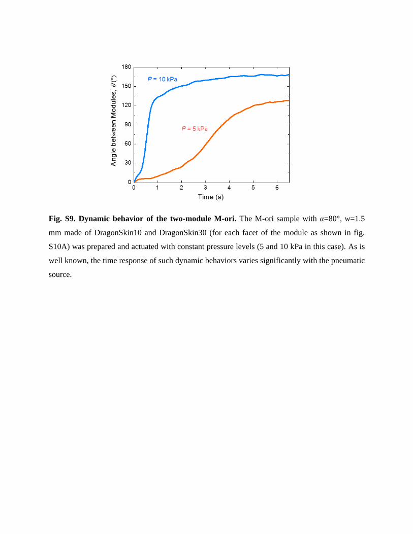
Fig. S9. Dynamic behavior of the two-module M-ori. The M-ori sample with α=80°, w=1.5
mm made of DragonSkin10 and DragonSkin30 (for each facet of the module as shown in fig.
S10A) was prepared and actuated with constant pressure levels (5 and 10 kPa in this case). As is
well known, the time response of such dynamic behaviors varies significantly with the pneumatic
source.
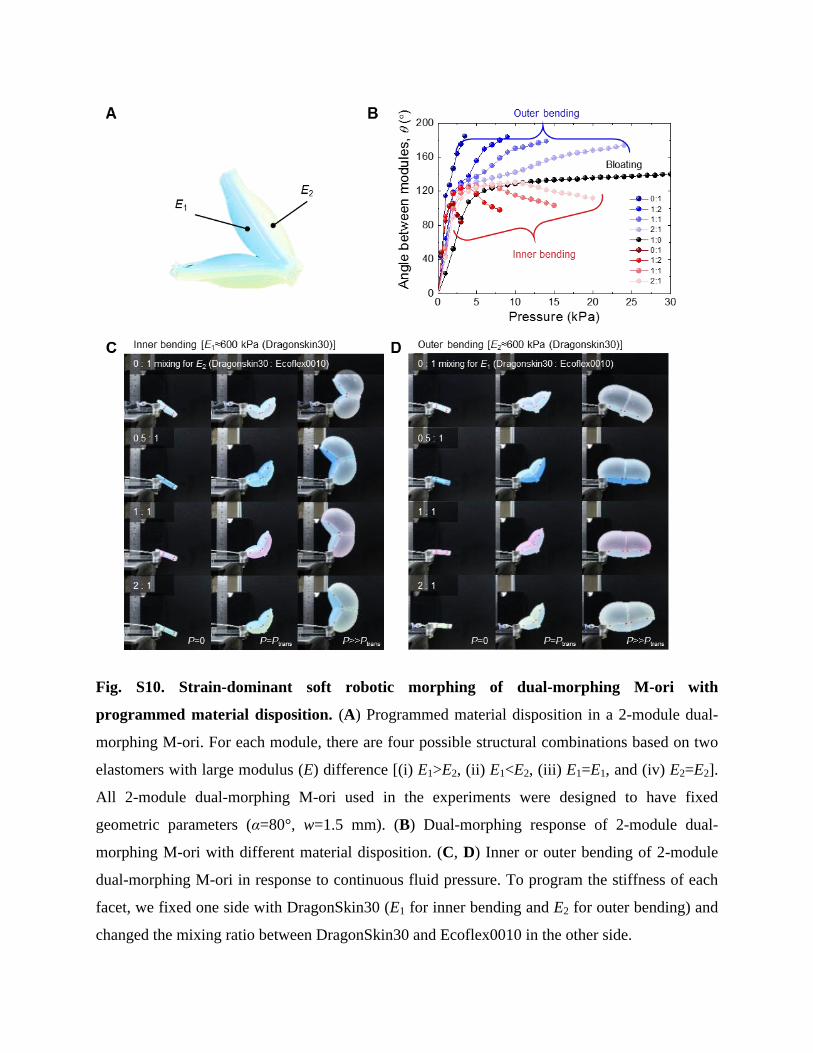
Fig. S10. Strain-dominant soft robotic morphing of dual-morphing M-ori with
programmed material disposition. (A) Programmed material disposition in a 2-module dual-
morphing M-ori. For each module, there are four possible structural combinations based on two
elastomers with large modulus (E) difference [(i) E1>E2, (ii) E1<E2, (iii) E1=E1, and (iv) E2=E2].
All 2-module dual-morphing M-ori used in the experiments were designed to have fixed
geometric parameters (α=80°, w=1.5 mm). (B) Dual-morphing response of 2-module dual-
morphing M-ori with different material disposition. (C, D) Inner or outer bending of 2-module
dual-morphing M-ori in response to continuous fluid pressure. To program the stiffness of each
facet, we fixed one side with DragonSkin30 (E1 for inner bending and E2 for outer bending) and
changed the mixing ratio between DragonSkin30 and Ecoflex0010 in the other side.
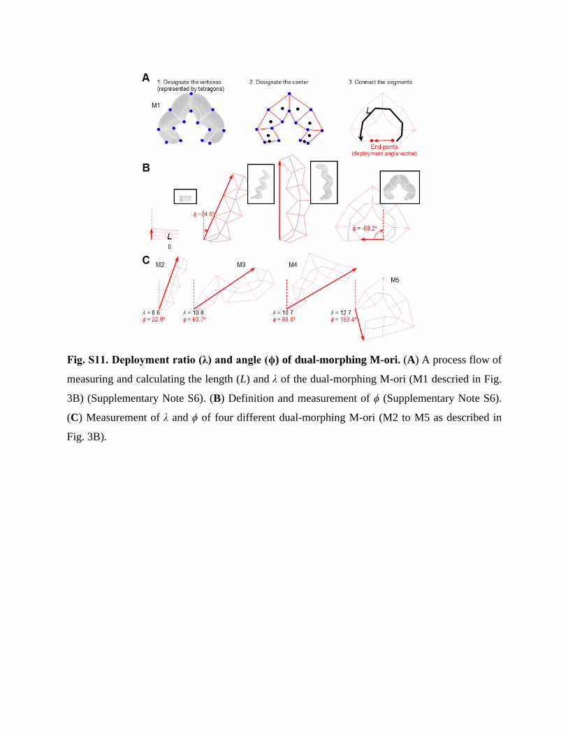
Fig. S11. Deployment ratio (λ) and angle (ϕ) of dual-morphing M-ori. (A) A process flow of
measuring and calculating the length (L) and λ of the dual-morphing M-ori (M1 descried in Fig.
3B) (Supplementary Note S6). (B) Definition and measurement of ϕ (Supplementary Note S6).
(C) Measurement of λ and ϕ of four different dual-morphing M-ori (M2 to M5 as described in
Fig. 3B).
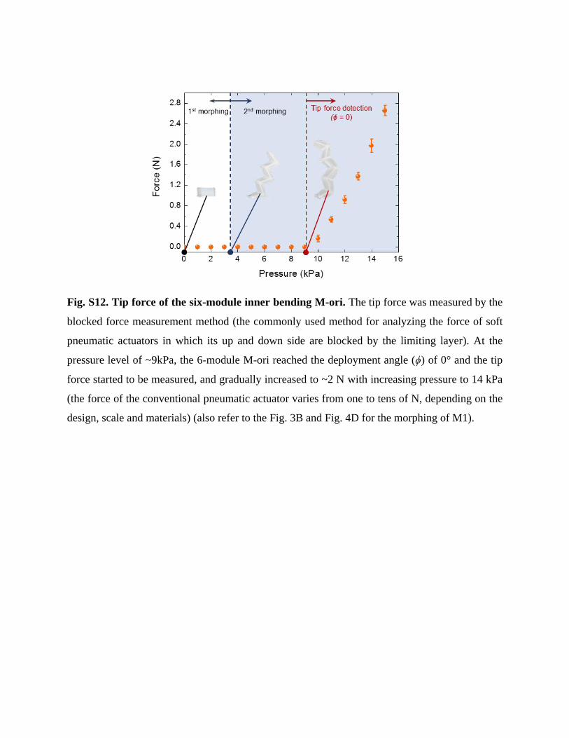
Fig. S12. Tip force of the six-module inner bending M-ori. The tip force was measured by the
blocked force measurement method (the commonly used method for analyzing the force of soft
pneumatic actuators in which its up and down side are blocked by the limiting layer). At the
pressure level of ~9kPa, the 6-module M-ori reached the deployment angle (ϕ) of 0° and the tip
force started to be measured, and gradually increased to ~2 N with increasing pressure to 14 kPa
(the force of the conventional pneumatic actuator varies from one to tens of N, depending on the
design, scale and materials) (also refer to the Fig. 3B and Fig. 4D for the morphing of M1).
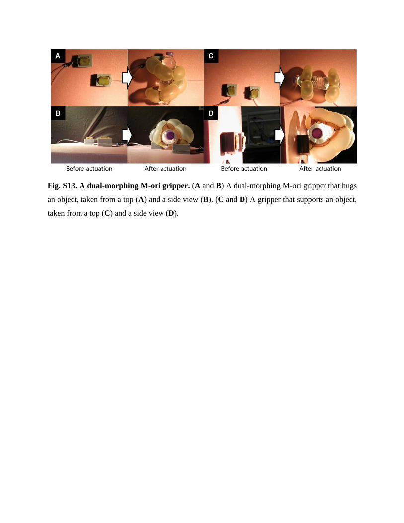
Fig. S13. A dual-morphing M-ori gripper. (A and B) A dual-morphing M-ori gripper that hugs
an object, taken from a top (A) and a side view (B). (C and D) A gripper that supports an object,
taken from a top (C) and a side view (D).
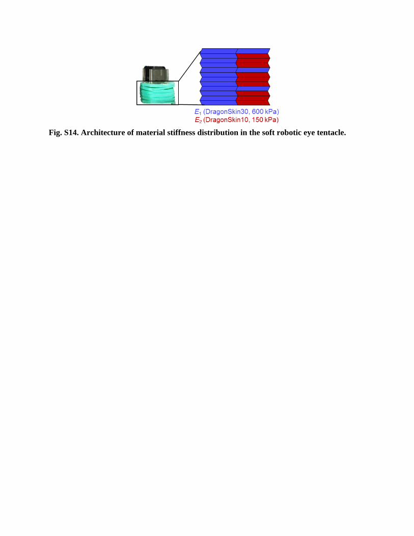
Fig. S14. Architecture of material stiffness distribution in the soft robotic eye tentacle.
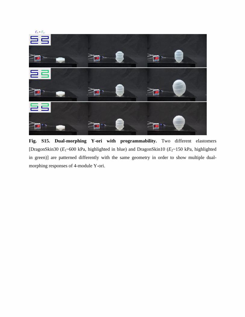
Fig. S15. Dual-morphing Y-ori with programmability. Two different elastomers
[DragonSkin30 (E1~600 kPa, highlighted in blue) and DragonSkin10 (E2~150 kPa, highlighted
in green)] are patterned differently with the same geometry in order to show multiple dual-
morphing responses of 4-module Y-ori.
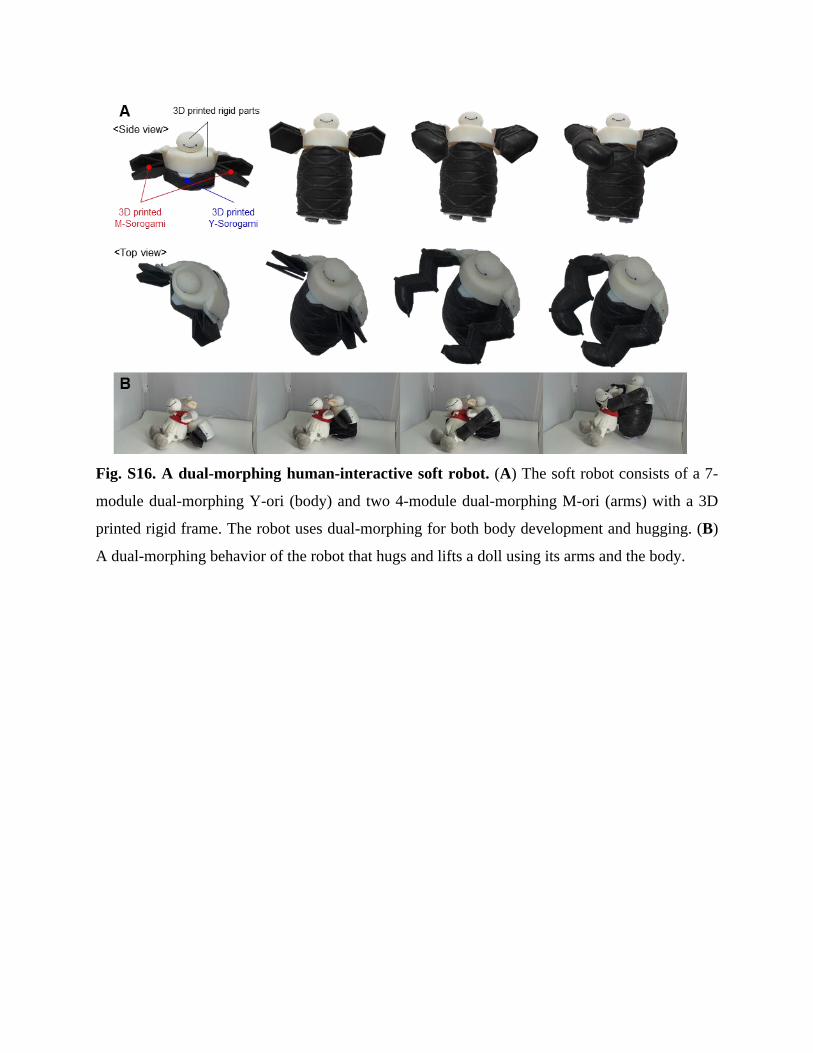
Fig. S16. A dual-morphing human-interactive soft robot. (A) The soft robot consists of a 7-
module dual-morphing Y-ori (body) and two 4-module dual-morphing M-ori (arms) with a 3D
printed rigid frame. The robot uses dual-morphing for both body development and hugging. (B)
A dual-morphing behavior of the robot that hugs and lifts a doll using its arms and the body.