Embed Size (px)
Citation preview

delta® Solenoid Metering PumpControl Module delta®
Supplementary instructions
Target group for these supplementary instructions: trained and qualified personnelThree sets of operating instructions are required for the safe, correct and proper operation of the metering pumps: Thesesupplementary instructions, the "General operating instructionsProMinent® solenoid metering pumps" and the "Operatinginstructions for the delta® solenoid metering pump with regulated solenoid drive optoDrive®". These are only valid whenread together.
Original Operating Instructions (2006/42/EC)Part no. 986236 BA DE 025 08/12 EN
Please carefully read these operating instructions before use! · Do not discard!The operator shall be liable for any damage caused by installation or operating errors!
Technical changes reserved.

986236, 2, en_GB
© 2012
ProMinent Dosiertechnik GmbHIm Schuhmachergewann 5 - 1169123 HeidelbergTelephone: +49 6221 842-0Fax: +49 6221 842-419email: [email protected]: www.prominent.com
2

In order to make it easier to read, this document uses the male form ingrammatical structures but with an implied neutral sense. It is aimedequally at both men and women. We kindly ask female readers for theirunderstanding in this simplification of the text.
Please read the supplementary information in its entirety.
The following are highlighted separately in the document:
n Enumerated lists
Instructions
ð Outcome of the instructions
Information
This provides important information relating to the correctoperation of the device or is intended to make your workeasier.
Safety information
The safety information includes detailed descriptions of the hazardous sit‐uation.
General non-discriminatory approach
Supplementary information
Supplemental instructions
3

Table of contents1 Introduction...................................................................................... 6
1.1 Safety and responsibility......................................................... 61.1.1 General Safety Information.................................................. 61.1.2 Specific safety instructions for the control module delta® .... 71.1.3 Correct and proper use........................................................ 8
2 Functional description...................................................................... 92.1 Application example control module delta®........................... 102.2 Connection in controlled pump operation.............................. 112.3 Electrical interfaces............................................................... 12
3 Installation..................................................................................... 163.1 Installation (hydraulic)........................................................... 163.2 Hydraulic test run after installation........................................ 173.2.1 Set the flow meter switching point...................................... 173.3 Commissioning sensors........................................................ 173.3.1 Run-in time......................................................................... 183.4 Switching of inductive loads.................................................. 18
4 Commissioning.............................................................................. 204.1 Initial Commissioning............................................................ 204.1.1 Selecting the operating language....................................... 204.1.2 Selection of the Measured Variable and Measuring
Range................................................................................. 20
5 Operating diagram/ Display Symbols............................................ 215.1 Overview of device / operating elements.............................. 225.1.1 Key functions...................................................................... 235.2 Continuous display add-on, control module delta®............... 235.3 Secondary display control module delta®.............................. 235.4 Activate/deactivate control module delta®............................. 245.5 Selection of the Measured Variable and Measuring Range.. 255.6 Setting the Limits................................................................... 265.7 Setting the basic load............................................................ 285.8 Setpoint adjustment.............................................................. 285.9 Checkout time adjustment..................................................... 305.10 Setting the delta® Control Module....................................... 325.11 Factory Settings of the control module delta®..................... 345.12 Setting up "Two pump operation"........................................ 355.12.1 Setting the controller pulse of the second pump.............. 365.13 Use of the current output of the delta®®............................. 375.14 Scaling the Output Value of the Analog Value.................... 38
6 Measured variables control module delta®.................................... 396.1 Calibrating the sensor for chlorine........................................ 406.1.1 Preparing the calibration of the sensor for chlorine ........... 406.1.2 Calibration of Zero Point and Gradient............................... 416.2 Sensor pH calibration............................................................ 436.3 Calibrating the sensor for Redox........................................... 44
7 Troubleshooting............................................................................. 457.1 Fault Status Display.............................................................. 467.2 Error control module delta® .................................................. 467.3 Warning Status Display......................................................... 477.4 Warnings control module delta® ........................................... 477.5 LED status displays of the control module delta®................. 48
8 Technical Data, Maintenance, Disposal........................................ 49
9 Index.............................................................................................. 50
Table of contents
4

1 Introduction
These operating instructions describe the technical data and functions ofthe control module delta®.
1.1 Safety and responsibility
1.1.1 General Safety Information
WARNING!Live parts!Possible consequence: Fatal or very serious injuries
– Measure: Disconnect the mains power supply prior toopening the housing
– De-energise damaged, defective or manipulated units bydisconnecting the mains plug
WARNING!Unauthorised access!Possible consequence: Fatal or very serious injuries
– Measure: Ensure that there can be no unauthorisedaccess to the unit
WARNING!Operating errors!Possible consequence: Fatal or very serious injuries
– The unit should only be operated by adequately qualifiedand technically expert personnel
– Please also observe the operating instructions for con‐trollers and fittings and any other component groups,such as sensors, measuring water pumps ...
– The operator is responsible for ensuring that personnelare qualified
CAUTION!Electronic malfunctionsPossible consequence: Material damage to destruction of theunit
– The mains connection cable and data cable should notbe laid together with cables that are prone to interfer‐ence
– Measure: Take appropriate interference suppressionmeasures
Introduction
5

NOTICE!Correct and proper useDamage to the product or its surroundings
– The unit is not intended to measure or regulate gaseousor solid media
– The unit may only be used in accordance with the tech‐nical details and specifications provided in these oper‐ating instructions and in the operating instructions for theindividual components
NOTICE!Correct sensor operation / Run-in timeDamage to the product or its surroundings
– Correct measuring and dosing is only possible if thesensor is working perfectly
– It is imperative that the run-in times of the sensors areadhered to
– The run-in times should be allowed for when planninginitial operation
– It may take a whole working day to run-in the sensor– Please read the operating instructions for the sensor
NOTICE!Correct sensor operationDamage to the product or its surroundings
– Correct measuring and dosing is only possible if thesensor is working perfectly
– Check and calibrate the sensor regularly
NOTICE!Compensation of control deviationsDamage to the product or its surroundings
– This controller cannot be used in control circuits whichrequire rapid compensation (< 30 s)
1.1.2 Specific safety instructions for the control module delta®
WARNING!Emergency stop switchPossible consequence: Fatal or very serious injuries
An emergency stop switch on the complete system. Thisshould enable the complete system to be switched off inevent of an emergency in such a way that the completesystem is stopped in a safe condition.
Introduction
6

WARNING!– Hazardous substances– Danger resulting from contact, breathing in or other con‐
taminations with / from substances or media– Observe the safety data sheet of the substances / media
used– The system operator must ensure that these safety data
sheets are available and that they are kept up to date
WARNING!– Unexpected starting after a failure, malfunction of the
controller / power supply or as an action wanted due to acontrol process
– Danger due to unexpected actions of the system– In event of a failure / malfunction of the controller or
power supply, the measuring / control station must bedisconnected from the power supply. For further informa‐tion, read the operating instructions of the devices andsensors used
NOTICE!– Secure the measuring / control station against unauthor‐
ised access– Please also observe the operating instructions for con‐
trollers and fittings and any other component groups,such as sensors, sample water pumps ...
– Observe the resistance of the wetted materials for allmodules (see also, e.g. also the ProMinent resistancelist in the product equipment catalogue or at www.promi‐nent.com)
– Protect the measuring / control station against directsunlight and other UV sources
– Observe the basic rules for ergonomic principles
1.1.3 Correct and proper use
NOTICE!Compensation for control deviationsDamage to the product or its surroundings
– The controller can be used in processes, which requirecompensation of > 30 seconds
NOTICE!Correct and proper useThe unit is intended to measure and regulate liquid media.The marking of the measured variables is located on thecontroller and is absolutely binding.
The unit may only be used in accordance with the technicaldetails and specifications provided in this operating manualand in the operating manuals for the individual components(such as, for example, sensors, fittings, calibration devices,metering pumps etc.).
Any other uses or modifications are prohibited.
Introduction
7

2 Functional description
The control module delta® expands the delta® pump series to includemeasurement dependent metering pumps. The control module delta®hasan active 4-20 mA input for combination with the measuring transducerspHV1, RHV1 or the chlorine sensor CLE-3mA. The control module delta®
has PID control characteristics so that the delta® solenoid metering pumpcan be optimally matched to process requirements. If a two-sided controlis required, a second pump can be controlled via the optional pacing relay.
For the [controlled pump] operating mode, the control module delta® mustbe connected to the DulcoFlow® DFMa ultrasonic flow meter. Both devicesare connected by the 4 ... 20 mA interface. The DulcoFlow® DFMa ultra‐sonic flow meter must be set to [controlled pump] operating mode; refer tothe operating instructions of the DulcoFlow® DFMa ultrasonic flow meter.
Table of measured variables: Assignment of the measured variable to the measuring input of the control module delta®
Measured variable mA input Part no. of the measuring transducer
Chlorine X
pH X* 809126
Redox X* 809127
Volume X**
Flow X**
*with measuring transducer
** with a flow meter
Brief functional description
Functional description
8

2.1 Application example control module delta®
7
8
6
5
1
3
4
2
A0345
Fig. 1: Application example of pH or redox system for one-sided control1. Sample water feed (30 - 60 l/h)2. Flow sensor (part of DGMA)3. pH sensor (PHEP 112SE) or redox sensor (e.g.
RHEP-Pt-SE)4. pH measuring transducer (pHV1 / 809126) or redox
measuring transducer (RHV1 / 809127)
5. Universal control cable (e.g. 1001300)6. External cable (2-pole / e.g. 707702)7. Tank with two-stage lance8. Relay cable (optional part of the delta® solenoid
metering pump)
Functional description
9

7
8
65
1
3
42
10
14
11
13
15
12
9
A0346
11
Fig. 2: Application example of pH or redox system for two-sided controlI. First pump delta® with control module delta®
II. Second pump e.g. Beta®
1. Sample water feed (30 - 60 l/h)2. Flow sensor (part of DGMA)3. pH sensor (e.g. PHEP 112SE) or redox sensor (e.g.
RHEP-Pt-SE)4. pH measuring transducer (pHV1 / 809126) or redox
measuring transducer (RHV1 / 809127)5. Universal control cable (e.g. 1001300)6. External cable (2-pole / e.g. 707702)7. Tank with two-stage lance
8. Optional relay cable (part of the delta® solenoidmetering pump)
9. Junction box 110. External cable (2-pole / e.g. 707702)11. Relay cable (3-conductor, part of the external pump)12. Junction box 213. Diaphragm rupture cable14. Suction lance15. Collective alarm
2.2 Connection in controlled pump operation
Connect the output of the flow meter (4 ... 20 mA round plug) to the inputof the delta®control module (4 ... 20 mA).
Functional description
10

2.3 Electrical interfaces
1.
2.
3.
I.
II.
III.
IV.
A0341
V.
VI.
Fig. 3: Connector box 1 (IP 65)1. Relay cable, 4 pin2. External cable for the second pump3. Fault indicating relay = external group alarm (max. load 24 V / 100
mA)I. White (pacing relay)II Brown (pacing relay)III. Yellow (fault indicating relay)IV. Green (fault indicating relay)V. WhiteVI. Brown
Connect the external pump using a 4 pin relay cable
A0342
Fig. 4: Connection of the flow sensorA. 5 pin universal cableI. BlackII. BrownIII. Blue (remains inactive)IV. Grey (remains inactive)V. White (remains inactive)
Functional description
11

Functional description: As soon as the flow rate drops below a setthreshold, the contact is opened and the delta® solenoid metering pumpswitches to ‘PAUSE’ .
1.
2.
I.
II.
III.
IV.
V.
VI.
VII.A0343
3.
Fig. 5: Connector box 2 (IP 65)1. Relay cable, 3 pin beta2. Delta diaphragm rupture cable3. Resistance 300 ΩI. White (open)II. Green (NC)III. Brown (C)IV. White (open)V. Blue (signal)VI. Black (ground)VII. Brown (5 V)
Connecting the alarm relay of the external pump to the input of the dia‐phragm rupture indicator of the delta® solenoid metering pump. As soon asthe external pump reports a fault, this fault is passed on to the delta® viathe input of the diaphragm rupture indicator. The delta® solenoid meteringpump stops and issues a group alarm.
Functional description
12

A0344
Fig. 6: Connection of the sensor or measuring transducer; 2-conductorexternal cableI. WhiteII. Brown
5-conductor universal cableHowever, when using a 5-conductor universal cable: I. black+ brown, bridged; and II. white
1
54
2
3
P_BE_0014_SW
Fig. 7: Control module assignments1 free2 Supply voltage approx. 25.5 volt3 GND4 Current input5 free
Functional description
13

2
45
1
3
P_BE_0015_SW
Fig. 8: Assignment on cable / 2-conductor external cable1 free2 Brown / supply voltage approx. 25.5 volt3 free4 White / current input5 free
Functional description
14

3 Installation
NOTICE!Mounting position and conditions– Ensure that there is unimpeded access for operation– Secure, low-vibration fixing– Avoid direct sunlight– Permissible ambient temperature at fixing position:
-10 ... + 45 °C at max. 95% relative air humidity (non-condensing)
NOTICE!Operating instructions for all components usedPossibility of material damage due to incorrect installation.
When installing the system also observe the operatinginstructions for all components used.
Read-off and operating position– Install the device at a favourable position for reading-off
and operating (preferably at eye level)
The control module delta® is fully integrated in the delta® solenoidmetering pump and does not require separate installation.
3.1 Installation (hydraulic)
CAUTION!– Observe the maximum permissible operating parameter
for the entire installation of the measuring / control sta‐tion (e.g. pressure, temperature, flow)
– In the process, observe the lowest maximum permissibleoperating parameter of the parts of the measuring / con‐trol and the sensors installed (see their operating instruc‐tions)
– Please also observe the operating instructions for con‐trollers and fittings and any other component groups,such as sensors, sample water pumps ...
– Observe the flow direction of the measured water.– One pressure reducer must be installed.– Danger resulting from media under pressure.– Before working with hydraulic parts of the measuring /
control station, this must be depressurised in a con‐trolled manner via the sampling cock.
– Wear protective goggles
Fittings
The bypass fitting (flow gauge) used depends particularly on the meas‐ured water, in some cases also from the measured variable or or the com‐bination of the measured variables. The type DGMA with flow controller isalways used for all clear water types and the type DLG III for contaminatedwater is also used for upstream flow controlling.
Hydraulic connection, pipework
Installation
15

With the DGMa, the hydraulic connection of the measured water is carriedout using an 8 x 5 mm hose connection. A shut-off ball valve is installedbefore and after the bypass fitting. The optionally available measuringwater filter is installed before the bypass fitting. Each of the bypass fittingshave a mounted sampling cock.
3.2 Hydraulic test run after installation
A hydraulic test run of the measuring / control station is necessary aftersuccessful installation.
n The sampling cock must be closed! Otherwise measured water willescape
n Check all screw connections before the initial commissioningn Open the shut-off ball valve on the inlet and outlet ends.n The system must now be hydraulically tight. No fluid must leak out.
If fluid should leak out, the reason for this must be determined and elimi‐nated.
3.2.1 Set the flow meter switching point 1. For testing, reduce the flow - the delta® Solenoid metering pump
must indicate ‘Pause’2. Check the screw connection for leaks.
The flow gauge DGMa:
Goal: Reduction in flow should switch - ‘Pause’ on thedelta® solenoid metering pump when the inlet is closed
1. Set the flow using the ball valve.
2. Set value: 40 l/h
3. Test value: 30 to 60 l/h (read-off from the top edge of the float)
4. Loosen the flow gauge.
5. Push the flow gauge upwards in the rail until thedelta® Solenoid metering pump switches to ‘Pause’ .
6. Push the flow gauge down far enough until ‘Pause’ on thedelta® solenoid metering pump has just cancelled.
7. Fasten the flow gauge.
8. For testing, reduce the flow
ð - the delta® Solenoid metering pump must switch to ‘Pause’ .
3.3 Commissioning sensors
WARNING!– Hazardous substances– Danger resulting from contact, breathing in or other con‐
taminations with / from substances or media– Observe the safety data sheet of the substances / media
used– The system operator must ensure that these safety data
sheets are available and that they are kept up to date
Installation
16

CAUTION!– The sampling cock must be closed! Otherwise measured
water will escape– The measured water must be free of air bubbles to guar‐
antee a reliable measurement and control! If air has tobe carried along in the measuring water due to theprocess, the air must be discharged using a suitabletechnical method.
– Please also observe the operating instructions for con‐trollers and fittings and any other component groups,such as sensors, sample water pumps ...
1. Retighten all screw connections and check for leaks.
2. Check the position of all shut-off valves. The position of the shut-offvalves must guarantee that the measuring / control station is tightand the flow of the measured water is given.
3. Commission the measuring / control station
3.3.1 Run-in time
A run-in time must be observed for the chlorine sensor. Depending on thesensor, this may vary between 1 hour and 24 hours. For this purpose, therespective sensor must be located in the measured water to be measuredand connected electrically. This measured water must already contain themeasured variables in a quality and quantity sufficient for the process.
The running-in of the sensors is described in the operating instructions ofthe sensor.
3.4 Switching of inductive loads
If you connect an inductive load, i.e. a consumer which usesa coil (e.g. an alpha motorised pump), then you must protectyour controller with a protective circuit. If in doubt, consult anelectrical technician for advice.
The RC member protective circuit is a simple, but nevertheless very effec‐tive, circuit. This circuit is also referred to as a snubber or Boucherotmember. It is primarily used to protect switching contacts.
When switching off, the connection in series of a resistor and capacitormeans that the current can fade out in a damped oscillation.
Also when switching on, the resistor acts as a current limiter for the capac‐itor charging process. The RC member protective circuit is highly suited toAC voltage supplies.
The magnitude of the resistance R of the RC member is determinedaccording to the following equation:
R=U/IL(U= Voltage divided by the load // IL = load current)
Units: R = Ohm; U = Volt; IL = Ampere; C = µF
Preparation
Installation
17
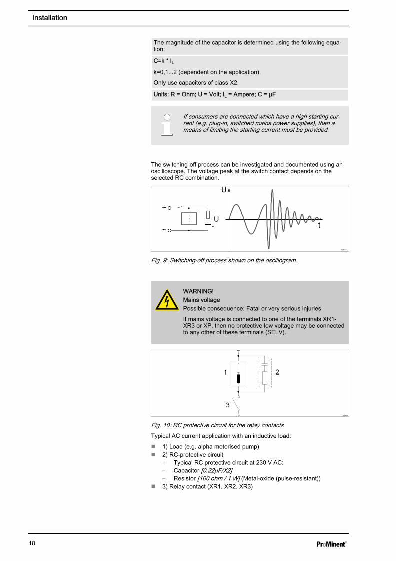
The magnitude of the capacitor is determined using the following equa‐tion:
C=k * ILk=0,1...2 (dependent on the application).
Only use capacitors of class X2.
Units: R = Ohm; U = Volt; IL = Ampere; C = µF
If consumers are connected which have a high starting cur‐rent (e.g. plug-in, switched mains power supplies), then ameans of limiting the starting current must be provided.
The switching-off process can be investigated and documented using anoscilloscope. The voltage peak at the switch contact depends on theselected RC combination.
A0842
Fig. 9: Switching-off process shown on the oscillogram.
WARNING!Mains voltagePossible consequence: Fatal or very serious injuries
If mains voltage is connected to one of the terminals XR1-XR3 or XP, then no protective low voltage may be connectedto any other of these terminals (SELV).
A0835
Fig. 10: RC protective circuit for the relay contactsTypical AC current application with an inductive load:
n 1) Load (e.g. alpha motorised pump)n 2) RC-protective circuit
– Typical RC protective circuit at 230 V AC:– Capacitor [0.22µF/X2]– Resistor [100 ohm / 1 W] (Metal-oxide (pulse-resistant))
n 3) Relay contact (XR1, XR2, XR3)
Installation
18

4 Commissioning
WARNING!Run-in time of sensorsThis can result is hazardous incorrect metering
Take into consideration run-in times when commissioning
– Correct measuring and metering is only possible if thesensor is working perfectly
– It is imperative that the run-in times of the sensors areadhered to
– The run-in times should be allowed for when planninginitial operation
– It may take a whole working day to run-in the sensor– Please read the operating manual for the sensor
4.1 Initial Commissioning
The control module delta® has the same language settings as the controlmodule delta® connected to the delta® solenoid metering pump.
4.1.1 Selecting the operating language
Setting the operating language is carried out via the setting menu of theconnected delta® solenoid metering pump.
4.1.2 Selection of the Measured Variable and Measuring Range
WARNING!Incorrect metering due to incorrect metering rangePossible consequence: Fatal or serious injuries
– The measuring range of the sensor is essential for themeasuring range!
– If the assignment of the measuring range is modified, thesettings must be checked in all menus
– If the assignment of the measuring range is changed,the sensor must be recalibrated
Commissioning
19
5 Operating diagram/ Display Symbols
Operation of the delta® solenoid metering pump with regu‐lated solenoid drive optoDrive®
The delta® solenoid metering pump with regulatedsolenoid drive optoDrive® operating instructions are availablefor basic operation of the delta® solenoid metering pump.The control module delta® operating instructions describe theadvanced operating options of the control module delta®
used in conjunction with the delta® solenoid metering pump.
Access to the settings for the control module delta®
To gain access to the settings of the control module delta®
you must stop the delta® solenoid metering pump using keySTOPSTART . The symbols and appear in the display. Only nowdo you have access to the settings for the control moduledelta®.
Operating diagram/ Display Symbols
20

5.1 Overview of device / operating elements
Contents of the LCD displayThe content of the LCD display can vary depending on theIdentcode of the delta® solenoid metering pump.
1
2
3
4
567
8
9
10
11
12
13
14
15
A0311
1617
Fig. 11: Operating elements of the delta® solenoid metering pump1 LCD display2 Stroke length adjustment knob3 UP key4 DOWN key5 Control module delta®
6 Device LED7 Connecting LED8 Relay insert (optional)9 Mains power
10 Terminal for the additional functions11 Sensor connection12 STOP / START key13 P key14 i key15 Operating indicator (green)16 Warning indicator (yellow)17 Fault indicator (red)
Operating diagram/ Display Symbols
21

5.1.1 Key functions
Key Operation In continuous displays
(Operation)
In setting mode
(Settings)
STOP / START key
STOPSTART
briefly pressed
(0.2 - 1 s)
stop pump
start pump
stop pump
start pump
P key briefly pressed
(0.2 - 1 s)
start batch (only in oper‐ating mode "Batch")
Confirm entry - Jump tonext menu option or in thecontinuous display
2 s pressed go to setting mode ----
3 s pressed ---- Return [ESCAPE] to thecontinuous display
i key
ibriefly pressed
(0.2 - 1 s)
toggle between the contin‐uous displays
----
long pressed
(> 1 s)
go to the second level of thecontinuous display
----
Arrow keys UP or DOWN individually pressed (untildouble arrows appear)
change directly adjustablevariables
select another setting.
change individual figure ornumber.
at the upper end of a selec‐tion, effect similar to theESC key
simultaneously pressed suction (in continuous dis‐play "stroke frequency")
----
5.2 Continuous display add-on, control module delta®
In the main display, extra displays for the control module delta® can beinserted in addition to the delta® solenoid metering pump displays.
The control module delta® displays are the values for the setpoint andactual values of the control module delta®.
n I. Setpoint A0950 (of the control module delta®) in very large portrayal(12x24 pixels) in the selected unit (ppm, pH, l/h or mV)
n II. Actual value [i] (Input value for the control module delta®) in verylarge portrayal (12x24 pixels) in the selected unit (ppm, pH, l/h or mV)
n III. Existing continuous displays of the delta® solenoid metering pump
Format for the main displays:
n A0950 = Setpointn Chlorine: A0950 XXX.YY ppmn pH: A0950 XX.YY pHn Redox: A0950 XXX mV
Display: Only the measured value is displayed = Actual value
Display: Measured value with a A0950 in front of it = Setpoint
5.3 Secondary display control module delta®
Both the setpoint value and the current actual value of the control moduledelta® are displayed In the secondary display.
A0950
Fig. 12: Setpoint symbol (12x24 pixels)
Operating diagram/ Display Symbols
22

n I. Setpoint A0951 (of the control module delta®) in the selected unit (ppm,pH, l/h or mV)
n II. Actual value [i] (input value of the control module delta®®) in theselected units (ppm, pH or mV)
n III. Current value (input value of the control module delta®) in xx.xx mAn IV. Existing continuous displays of the delta® solenoid metering pump
Format for the secondary displays
n ( A0951 = Setpoint):n Chlorine: A0951 XXX.YY ppmn pH: A0951 XX.YY pHn Redox: A0951 XXX mVn Flow rate: A0951 XX.XX l/h
Display: Only the measured value is displayed = Actual value
Display: Measured value with a A0951 in front of it = Setpoint
5.4 Activate/deactivate control module delta®
The following menu is used to place the delta® solenoid metering pump incontrol module delta® operating mode.
A0312
Clear
Main
proControlSet
P P
P
Active
proControlInactive
Active
proControlInactive
Operation
Fig. 14: Activate/deactivate control module delta®
If the control module delta® is ‘switched’ to active then regulation or con‐trol of the delta® solenoid metering pump is carried out by thecontrol module delta®. This independent of which operating mode thedelta® solenoid metering pump was previously in. If the control moduledelta® is switched to ‘inactive’ , then the delta® solenoid metering pumpreturns to its original operating status.
In the inactive state, no error or warning messages are transferred to thedelta® solenoid metering pump.
If the control module delta® was ‘switched’ to active then the symbol appears in the operating indicator of the delta® solenoid metering pump tosignal that the control module delta® is working in active mode. At the same time,the ‘Connection LED’ switches to green in control mode.
The [display text] for the operating mode displays the text ‘↑ increase’ or ‘↓ decrease’ .In the [controlled pump] operating mode, [flow] is shown.
A0951
Fig. 13: Setpoint symbol (8x8 points)
Operating diagram/ Display Symbols
23

5.5 Selection of the Measured Variable and Measuring Range
The delta® control module has a 4 - 20 mA input. A sensor can be con‐nected to this input. The control parameters, the menus and the contin‐uous display are sensor-specific.
A0320
Clear
MainproControlSetSet ControllerController
SetSensor calibr.
Concentration
Controller
Sensor typeSensor type2. Pump
pH pH Sensor type
Sensor typeMeas.Range = [10.0] ppm
ChlorineRedox
pH Sensor type
ChlorineChlorineRedox
pH Sensor type
ChlorineRedoxRedox
Language Aux.
Hardware calib.Reg. work set
Sensor TypeChlorine
DulcoFlowDulcoFlowRedox
Fig. 15: Selection of the Measured Variable and Measuring RangeYou can select the appropriate sensor under the menu option ‘Sensortype’ . You can also select the different variants or measuring ranges of thesensors in this menu option.
Operating diagram/ Display Symbols
24

Sensors Types
Redox Only one sensor variant, is operated with the "RhV1" measuring transducer.
n 1000 mV 20 mAn 0 mV 4 mA
Chlorine n Measuring range from 0 ... 20 ppm
pH Only one sensor variant, is operated with the "pHV1" measuring transducer.
n -500 mV ~ pH 0 20 mAn 500 mV ~ pH 14 4 mA
DulcoFlow® The [controlled pump] operating mode only works together with the DulcoFlow® flow meter. It ispossible to select between different operating modes:
n [Controlled pump], when the pump is operated in [manual] mode.– 0.01 ... 80.00 l/h
n [Volume metering], when the pump is operated in [batch] mode.– 0.01 ... 10.00 l/h
"Controlled pump" operating modeIn the [controlled pump] operating mode (volume metering),the minimum stroke frequency of the pump is 4 strokes; themetered quantity (volume) must always be set so that thepump requires ≧ 4 pump strokes for this quantity. Oncemetering of a quantity has started, this can be stopped withthe [Start/Stop] key; volume metering is then stopped.
5.6 Setting the Limits
HysteresisBuilt-in hysteresis ensures that the control module delta®
does not continuously switch between control and base loadmetering in the limit value range.The hysteresis is approx 2 % of the measuring range:– ( ‘upper limit value’ minus ‘lower limit value’ ) * 2 %
Valid limit values can be set for the control of each sensor type. The con‐trol is adjusted when a measured value is outside of the limit value. In thiscase, only basic load control is active.
If the measured value is outside of the limit value, a warning is emitted andthe symbol ! is output to the status display of the delta® solenoidmetering pump.
Operating diagram/ Display Symbols
25

A0313
Clear
Main
proControlSet
Controller
SetSensor calibr.
low: 0.0 ppm
Limit valuehigh: 10.0 ppm
Concentration
Chlorine sensor
Limit value
Controller
Basic loadParameter
or
or
pH sensor
Redox sensor
low: 3.0 pH
Limit valuehigh: 12.0 pH
low: 200 mV
Limit valuehigh: 700 mV
Operation
Aux.
Setpoint
low: 0.0 ppm
Limit valuehigh: [10.0] ppm
Chlorine sensor
or
or
pH sensor
Redox sensor
low: 3.0 pH
Limit valuehigh: [12.0] pH
low: 200 mV
Limit valuehigh: [700] mV
Fig. 16: Setting the Limits
Sensor Factory setting Settings
upper lower
Chlorine 0 ppm 20 ppm 0 ppm to the maximum value of the sensor In steps of 0.1 ppm
pH 0 pH 14 pH 0 pH to 14 pH. In steps of 0.1 pH
Redox 0 mV 1000 mV 0 mV to 1000 mV. In steps of 1 mV
Flow -- -- No limit values can be set for this.
Volume -- --
Operating diagram/ Display Symbols
26

5.7 Setting the basic load
Basic loadIt may be necessary to meter the feed chemical with a basicload.
You can switch the basic load control on or off using this menu. Youswitch the basic load on by entering a percentage proportion of the max‐imum set value.
A0314
Clear
Main
proControlSet Controller
SetSensor calibr.
[ 5 ] %
Basic load
Concentration
Basic load
ControllerSetpoint
Limit value
Operation
Aux.
Parameter
Fig. 17: Setting the basic load
Basic load Settings
Setting values 0 % to 100 % in increments of 1 %. Start value of 0 %. 0% = Basic load off.
5.8 Setpoint adjustment The setpoint can be set from this menu. In the continuous display a A0951 isplaced in front of the setpoint display value.
A0363
Clear
Main
proControlSet Controller
SetSensor calibr.
[ 500 ] mV
Setpoint
Concentration
Basic load
ControllerSetpoint
Limit value
Operation
Aux.
Parameter
Fig. 18: Setpoint adjustment
Operating diagram/ Display Symbols
27

Setting Possible values
Display Starting value Increment Lower value Upper value Remark
mV 500 mV 1 mV 0 mV 999 mV Redox
pH 7,00 pH 0,01 pH 0,00 pH 14,00 pH
Chlorine 5.00 ppm 0.01 ppm 0 ppm 20 ppm
The upper and lower value can only be set within the range of the set limit values, see Ä Chapter 5.6 ‘Setting theLimits’ on page 25. The values in the table show the maximum possible range.
Settings for the "controlled pump" operating mode
Setting Possible values
Display Starting value Increment Lower value Upper value Remark
l/h 0 10 ml/h 0.01 l/h 80.00 l/h In ‘Manual’ operatingmode:
l 0 10 ml 0.01 l 10.00 l In ‘Batch’ operatingmode:
Operating diagram/ Display Symbols
28

5.9 Checkout time adjustment
Monitoring of the control pathThe checkout time monitors the control path. The checkouttime mechanism permits detection of possible defective sen‐sors.
A0315
Clear
Main
proControlSet
Controller
SetSensor calibr.
[120] min
Check out time
Concentration
Check out time
Controller
Limit valueBasic load
Operation
Aux.
Parameter
Fig. 19: Checkout time adjustment
Determining the dead time and setting the checkout time
Each control path has a dead time. The dead time is the time, which thecontrol path requires to detect a change or addition of metered chemicalsusing its own instrumentation.
You must select the checkout time so that it is greater than the dead time.You can determine the dead time, by operating the metering pump inmanual mode and, for example, metering acid.
NOTICE!Dead time determinationYou should only determine the dead time if the currentprocess cannot be negatively influenced by manualmetering.
You must determine the time, which the control path (i.e. the entirety ofcontrollers, sensors, measurement water, in-line probe housings, etc.)requires to detect a first change in the measured value starting from thebeginning of metering. This time is the ‘dead time’ . A safety margin, e.g.25%, must be added to this dead time. You must allocate an appropriatesafety margin for your own particular process. If after the checkout timehas elapsed, the setpoint is not reached, see Ä Chapter 5.8 ‘Setpointadjustment’ on page 27, the metering pump switches to base loadmetering.
If the control module delta® has not reached the defined thresholds oncethe checkout time has elapsed, then the control module delta® switchesover to base load operation. In the higher-level system, in this case thedelta® solenoid metering pump, a warning is emitted and the symbol isoutput to the status display of the delta® solenoid metering pump.
In [controlled pump] operating mode, the symbol indicates that therequired flow rate (setpoint) has not been reached. It may be that the set‐point flow rate is too high or that the pump capacity is too low. However,the delta® solenoid metering pump does not switch to basic load on thisfault message (in [controlled pump] operating mode), but continues towork in normal mode.
Operating diagram/ Display Symbols
29

The threshold value equals 90 % of the setpoint. This value(90 % of the setpoint) must be achieved within the checkouttime.
set-up Comment
set-up 1 min to 999 min in 1 min steps
Starting value Off = 0 min)
If the control module delta® is in ‘checkout time’ mode, then base loadmetering is active. However it you want to return to normal control mode,then the control time must be restarted. To restart the control time, the STOP
START
key must be pressed.
Resetting after activation of the checkouttime
Operating diagram/ Display Symbols
30

5.10 Setting the delta® Control Module
"Controlled pump" operating modeThis setting menu does not exist in[controlled pump] oper‐ating mode. These control parameters are set in the factoryin [controlled pump] operating mode.
The control path can be set in this menu. First, the feed chemical to bemetered out must be selected, e.g. "increase" or "decrease".
A0316
Clear
Main
proControlSet
Controller
SetSensor calibr.
Concentration Basic load
Controller
Parameter
Limit value
↓Lower
Parameter↑Raise
↓Lower
Parameter↑Raise
Chlorine sensor
pH sensor
Redox sensor
↑Raise
↑Raise
↑Raise
Xp = [1.0] ppmTn = 10 secTv = 10 sec
Xp = [1.0] pHTn = 10 secTv = 10 sec
Xp = [1.0] mVTn = 10 sec
↑RaiseXp = 1.0 ppmTn = [10] secTv = 10 sec
↑RaiseXp = 1.0 ppmTn = 10 secTv = [10] sec
Operation
Aux.
Setpoint
Tv = 10 sec
Fig. 20: Setting the control module delta®
The parameters for the control path can then be set. These are:
n Xp KP (reciprocal proportional coefficient)n Ti is the reset time of the I-controller (integral controller) in seconds.n Tv is the derivative action time of the D-controller in seconds.
Operating diagram/ Display Symbols
31

Ti Td Controller
0 0 P controller
>0 0 PI controller
0 >0 PD controller
>0 >0 PID controller
Sensor Parameter Comment
Chlorine Setpoint 0.01 ppm to the upper limit of the measuring range. In steps of 0.01 ppm. Initialvalue: 50 % of the measuring range
Xp 0 to measuring range in steps of 0.01 ppm. Initial value: 10 % of the measuringrange
Ti 0 s to 9999 s in steps of 1s. Initial value 0 s.
Td 0 s to 9999 s in steps of 1s. Initial value 0 s.
pH Setpoint pH 0.01 pH to 14 pH in steps of 0.01 pH. Initial value 50 % of measuring range
Xp 0 pH to the measuring range in steps of 0.01 pH. Initial value: 10 % of the meas‐uring range
Ti 0 s to 9999 s in steps of 1s. Initial value 0 s.
Td 0 s to 9999 s in steps of 1s. Initial value 0 s.
Redox Setpoint 0 mV to 1000 mV in steps of 1 mV. Initial value: 50 % of the measuring range
Xp 0 mV to 1000 mV in steps of 1 mV. Initial value: 10 % of the measuring range
Ti 0 s to 9999 s in steps of 1s. Initial value 0 s.
Td 0 s to 9999 s in steps of 1s. Initial value 0 s.
Operating diagram/ Display Symbols
32
5.11 Factory Settings of the control module delta®
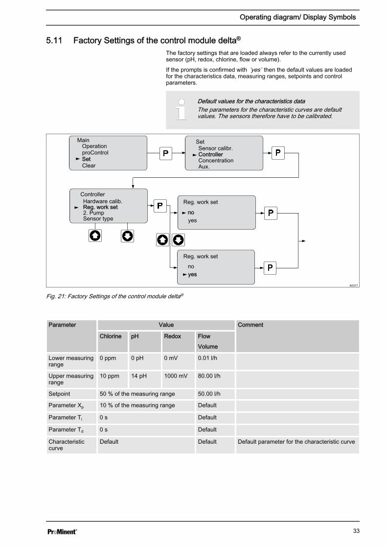
The factory settings that are loaded always refer to the currently usedsensor (pH, redox, chlorine, flow or volume).
If the prompts is confirmed with ‘yes’ then the default values are loadedfor the characteristics data, measuring ranges, setpoints and controlparameters.
Default values for the characteristics dataThe parameters for the characteristic curves are defaultvalues. The sensors therefore have to be calibrated.
A0317
Clear
Main
proControlSet
Controller
SetSensor calibr.
Concentration
Reg. work set
Controller
Sensor type2. Pump
yesno
yesno
Reg. work set
Reg. work set
Operation
Aux.
Hardware calib.
Fig. 21: Factory Settings of the control module delta®
Parameter Value Comment
Chlorine pH Redox Flow
Volume
Lower measuringrange
0 ppm 0 pH 0 mV 0.01 l/h
Upper measuringrange
10 ppm 14 pH 1000 mV 80.00 l/h
Setpoint 50 % of the measuring range 50.00 l/h
Parameter Xp 10 % of the measuring range Default
Parameter Ti 0 s Default
Parameter Td 0 s Default
Characteristiccurve
Default Default Default parameter for the characteristic curve
Operating diagram/ Display Symbols
33

5.12 Setting up "Two pump operation"
"Controlled pump" operating modeThis function is not supported in [controlled pump] operatingmode.
The control module delta® can also be operated in two pump operation. Todo this different parameters can be entered for the second pump.
Clear
Main menu
proControlSet-up
Controller
Set-upsensor. calibr.
Concentration
checkout timeController
res. fact. Set. 2nd pump
2nd pumpactivate
no
activateyes
spm: [120]
2nd pumpactivate
volume 25.0 l/h
2nd pumpactivatespm: 120volume [25.0 l/h]
no
activateyes
A0324
Operation
Aux.
hardware calib. spm: 120volume 25.0 l/h
2nd pumpactivatespm: 120
Dead zone : 0,2 pH
Dead zone : 0,2 pH
volume 25.0 l/hDead zone : 0,3 pH
Fig. 22: Setting up "Two pump operation"The control module delta® now directly controls the second pump via therelay output of the delta® solenoid metering pump.
set-up Comment
Activate The control is only active if the control relay in the delta® solenoid metering pump has been acti‐vated.
Strokes/min. Pump stroke rate in strokes/minute. Maximum 180/min.
Volume Volume in l/hour
Dead zone During switching over of metering from pump 1 to pump 2 there is an interval during which nopump is metering. This interval is the dead zone.
Operating diagram/ Display Symbols
34

5.12.1 Setting the controller pulse of the second pump
NOTICE!Calibrating the delta® solenoid metering pumpTo enable the second pump to be controlled by thedelta ® solenoid metering pump, thedelta® solenoid metering pump must have been calibrated.Notes for this purpose: Operating instructions "Solenoidmetering pump delta® with controlled solenoid drive opto‐Drive®", chapter ‘Settings for the function “Calibration”(CALIBRATION menu)’
Depending on the pump type that should be connected to the control relayof the delta® solenoid metering pump, it is necessary to set the controllerpulse accordingly. The controller pulse can be a growing or a falling pulseof the controller relay. Take note that this menu can only be called upwhen a control relay has been installed in thedelta® solenoid metering pump.
A0319
Clear
Main
proControlSet Relay
Set
Metering
System
Relay 2
Relay
WarningRelay 2
Option
Relay 2[100] /min at 100 %
Warning+error
Operation Calibrate
Relay 1
Pulse
Fig. 23: Menu for adjusting the controller pulse of the second pump
Operating diagram/ Display Symbols
35

5.13 Use of the current output of the delta®®
It is possible, using the current output of the delta® to output the currentwhich is measured at the control module current input. To enable thisfunction, the control relay with current output must be installed in thedelta®.
Hence this menu can only be called in the display if a controlrelay with current output is installed in the delta®.
Clear
Main menu
proControlSet upSet up
Analog outputAnalog output
Set upMeteringRelay
Analog output
Measured value module%Measured value module%A0952
Operation
Bleeding
strokes /hl/h * stroke lengthPower at 20 mA
Fig. 24: Current output activation menu
Operating diagram/ Display Symbols
36

5.14 Scaling the Output Value of the Analog Value
You can control the control module of the delta® with the analog module ofthe delta®.
Security
Main menu
proControlset-up
Controller
Set-upCont. calib. I
Concentration
Basic loadController
Analog scaling
Analog scaling
Analog scaling
Analog scaling
A1181
Operation
Checkout time upper:
Analog scaling
lower:
upper: lower:
upper: lower:
upper: lower:
Fig. 25: Scaling the Output Value of the Analog ValueI. Chlorine sensorII. pH sensor
III. ORP sensorIV. DulcoFlow®
By scaling the output value of the analog value, you can assign the meas‐ured value to be output for a given current value (0 mA value= lowermeasured value / 20 mA value = upper measured value)
Scaling values can be set for each sensor type:
Factory settings
Sensor Lower value Upper value Adjustment range
Chlorine 0 ppm 20 ppm 0 ppm to the maximum value of the sensor in steps of 0.1 ppm
pH 0,00 pH 14,00 pH 0 ... 14 pH in steps of 0.1 pH
mV 0 mV 1000 mV 0 ... 1000 mV in steps of 1 mV
DulcoFlow® 0.00 l/h 10 l/h 0.00 ... 80.00 l/h in steps of 10 ml/h
Operating diagram/ Display Symbols
37

6 Measured variables control module delta®
WARNING!Danger of incorrect meteringThis can result in hazardous incorrect metering
During initial commissioning, the measured variable and themeasuring range of the sensor must be set prior to calibra‐tion.
During all work on or with the sensors, also observe the rele‐vant technical documentation of the sensors.
Sensor measuring rangeYou must match the controller measuring range to the meas‐uring range of the chlorine sensor used.
Measured variable Default measuring range
Chlorine 10 ppm
The measuring ranges can be continuously adjusted from 0.5 ... 20 ppm.
pH Measured variable Typical measuring range
Measuring range 0 ... 20 mA
Display range At least pH -1.45 … 15.45
Reference temperature + 25 °C
Resolution 0,01 pH
Redox measured variable Typical measuring range
Measuring range 0 mV ... + 1000 mV
Resolution 1 mV
DFMa measured variable Typical measuring range
Measured variables control module delta®
38

6.1 Calibrating the sensor for chlorine
Clear
Main
proControlSet
Controller
SetSensor calibr.
Concentration
Calibr. values
Sensor calibr.
DPD adjustAdj.zero point.
Z. point [4.10] mA
DPD: [3.00] ppmDPD adjust
Calibr. values
Sensor calibr.
DPD adjustAdj.zero point.
Calibr. values
Sensor calibr.
DPD adjustAdj.zero point.
Adj.zero point.
Z. point 4.10 mASlope 1.18 mA/ppm
DPD adjust
Calibr. valuesZ. point [4.10] mASlope 1.18 mA/ppm
A0321
Operation
Aux.
continue with P
Adjust. valuesZ. point 4.10 mASlope 1.18 mA/ppm
Fig. 26: Calibrating the sensor for chlorine
6.1.1 Preparing the calibration of the sensor for chlorine
CAUTION!Correct sensor operation / Run-in timeDamage to the product or its surroundings
– Correct measuring and metering is only possible if thesensor is working perfectly
– Please read the operating manual for the sensor– Please also read the operating manuals for the fittings
and other components used– It is imperative that the run-in times of the sensors are
adhered to– The run-in times should be allowed for when planning
initial operation– It may take a whole working day to run-in the sensor
Necessity of calibrating the zero pointCalibration of the zero point is not generally necessary. Cali‐bration of the zero point is only necessary if the sensor isoperated at the lower limit of the measuring range or if the0.5 ppm sensor version is used.
Measured variables control module delta®
39

During the calibration, the control module delta® sets the actuating outputsto ‘0’ . The mA standard signal outputs are frozen. The reading frozen atthe start of calibration is suggested as a DPD value. The DPD value canbe set using the arrow keys.
6.1.2 Calibration of Zero Point and Gradient
NOTICE!Prerequisites for correct calibration of the sensor gradient– The DPD method required by the metering medium
employed will be used– The run-in time for the sensor has been adhered to– There is permitted and constant flow at the flow gauge– There is temperature equalisation between the sensor
and the sample water– There is a constant pH value in the permitted range
The sensor is fitted, flushed with sample water and connected electricallyto the control module delta® and run-in.
There has to be adequate metering medium in the sample water for cali‐bration (> 2% of the measuring range of the sensor).
Remove sample water directly at the measuring point and using an appro‐priate reference method (e.g. DPD, titration etc.), determine the content ofmetering medium in the sample water in ‘ppm’ . Enter this value in thecontrol module delta® as follows:
1. Select the calibration menu [Sensor Calibration]. The press thebutton
2. Take a sample of water and perform a reference measurementimmediately.
3. Select the unit ‘DPD adjust’ to be calibrated using the buttons or
4. The press the button
ð The current reading will now be frozen.
5. When necessary, adapt the ppm value determined using keys and
ð The ppm value of the sensor shown in this display now corre‐sponds to the reading in ‘ppm’ .
6. The press the button
ð The display now shows the value determined for the zero pointand gradient. Refer to the Error Message table should an errorbe displayed
Necessity of calibrating the zero pointCalibration of the zero point is not generally necessary. Cali‐bration of the zero point is only necessary if the sensor isoperated at the lower limit of the measuring range or if the0.5 ppm sensor version is used.
Calibrating the chlorine sensor: slope
Measured variables control module delta®
40

A container with water, which is free of additives that could falsify themeasured result, is needed for calibration. Immerse the sensor removedthat is still connected to the control module delta® electrically into thiswater. Stir the sensor around the water for approx. 5 minutes until thereading on the on the control module delta® is displayed steady and closeto ‘0’ .1. Select the calibration menu [Sensor Calibration]. The press the
button
2. Select the unit ‘Adj. zero point’ to be calibrated using the buttons or
3. Continue with
ð A prompt is shown in the display
4. Adapt the ‘ Zero point’ value displayed during the calibration usingthe buttons or and when necessary, accept the value usingthe button
ð Refer to the Error Message table should an error be displayed
NOTICE!Then definitively calibrate the gradient with a suitable refer‐ence method (e.g. DPD. titration etc.).
Calibrating the chlorine sensor: Zero point
Measured variables control module delta®
41

6.2 Sensor pH calibration
Security
Main menuOperation
Set-up Controller
Set-upsensor. calibr.
Concentration
sensor. calibr.
sensor. calibr.
calib pHactual values
calib pHprobe in buffer 1
calib pHcal. runs4,00 pH
calib pHBuffer 1: 4,00 pHTemp: 25.0 °C
calib pH
probe in buffer 2
calib pHcal. runs 7,00 pH
calib pHBuffer 2: 12,00 pHTemp: 25.0 °C
calib pH
continue with P
calib pHactual values
calib pH zero point [10,0] mVslope at 25 °C- 59,0 mV/pH
A0322
proControl
Aux.
continue with P
continue with P
continue with P
actual valueszero point [10,0] mVslope at 25 °C- 59,0 mV/pH
Fig. 27: Sensor pH calibration
Measured variables control module delta®
42

6.3 Calibrating the sensor for Redox
Main
proCONTROLSet
SetSensor calibr.
Sensor calibr.Calibr. Redox
Calibr. RedoxBuffer 1: 220 mVBuffer 2: 465 mV
Buffer 220 mV
Meas.Value 225 mV
Adjust noAdjust yes
Clear
ControllerConcentration
Calibr. RedoxBuffer 1: 200 mVBuffer 2: 465 mV
Buffer 465 mV
A0323
Operation
Aux.
Offset: 0 mV
Meas.Value 465 mV
Adjust noAdjust yesOffset: 0 mV
Fig. 28: Calibrating the sensor for Redox
Measured variables control module delta®
43

7 Troubleshooting
Operating display
Main display
Sub-display Unit
Display status
Sta
tus
disp
lay
Uni
t, w
hen
app.
ad
ditio
nal i
nfo
Priority
Prio
rity
Error symbol
Err
or s
ymbo
l
Fig. 29: Overview of the operating indicator of the delta® solenoid metering pump
Operating indicator con‐trol module
Standard indicator in control mode. If the control module delta® is not acti‐vated, then the symbol is not displayed.
Troubleshooting
44

7.1 Fault Status Display
In the inactive state of the delta® control module, no fault or warning mes‐sages are transferred to the delta® solenoid metering pump.
The symbol appears in the LCD display. The corresponding faultsymbol flashes in the main display. If several faults are incoming thenthese are shown in order of their occurrence.
Image Fault Description
! Control module A fault/error was detected in the control module delta®
n EEProm faultn Data errorn If the ! symbol is also displayed in the ‘status display’ field, then a fault
has been detected when calibrating the redox sensor (deviation from buf‐fered value >+/- 40 mV)
i < 4 mA Control module A value less than 4 mA is measured at the current input.
i > 20 mA Control module A value greater than 20 mA is measured at the current input.
20 mA! Control module The 20 mA interface has been set to fault status
n Short circuitn Overcurrent (> approx. 50 mA)n Countervoltage (< 0 V)
Missing controlmodule
Missing optional module or no communication established with the optionalmodule
If the optional "control module" was switched to active condition, then the delta®
solenoid metering pump expects the control module delta® to register. Thissymbol is shown if it does not register
DulcoFlow®
errorThis error symbol is displayed when:
n The flow meter is not connected electrically to the control module.n There is a fault in the flow meter (e.g. air in the measuring head)n The flow meter is not in ‘controlled pump’ operating mode
7.2 Error control module delta®
Error Description
Hardware error A hardware error has been detected
n Access error to EEPromn Overcurrent / undercurrent sensorn Communication error
Software / data Configuration values cannot be used, e.g. the control parameters (XP, TV, TN) are all set tozero.
Troubleshooting
45

7.3 Warning Status Display
The display flashes The bottom line gives an explanation of the warning.In this condition the control module delta® is still operational.
Image Warning Description
! Control module A warning from the control module delta®) has been detected
n Feedforward control error (control module delta®) continues to worknevertheless)
n Overflow of the control module output value (control module delta®)continues to work nevertheless)
n A communication error between the pump ® and control module delta®
has been detected. The connection LED illuminates in red.
Checkout time A warning from the control module delta®) has been detected
n Checkout time elapsed (control module delta®) works in basic load)
! Limit The limit has been exceeded/undershot
n The delta® control module is in basic load control mode
! Calibration A calibration error has been detected
If an error has been detected, the calibration data are not adopted. Opera‐tion continues with the old calibration data. This relates to the calibrationfor the current interface and the sensors. If a warning is displayed during asensor calibration, then this may refer to sensor error.
DulcoFlow® This warning is displayed when a fault that has previously occurred hasnow disappeared. This can happen, e.g. when gas bubbles have formedthat have cleared themselves.
7.4 Warnings control module delta®
Warning Description
Communication A continuous communication error has been determined
Software / data n Configuration values are inconsistentn Communication error (unknown reply, wrong checksum)
Controllers n Limit value undershot / exceededn Checkout time elapsed
Troubleshooting
46

7.5 LED status displays of the control module delta®
The LED status displays signal the current operating status of the controlmodule delta®. There are different LED status displays: The devices LEDand the Connection LED. The LED status displays do not have a flashingmode.
Devices LED
LED Status
Green Operating indicator
Red Fault display
n Internal hardware errorn Sensor error
Orange Warning indicator
n Configuration errorn limit valuen Checkout time
Connection LED
LED Status
- Passive controller operation, otherwise OK
Green Active control operation
Red No connection to the pump
Communication error
Troubleshooting
47

8 Technical Data, Maintenance, Disposal
Current input
Value
Measuring range 0/4 mA - 25 mA (at 50 ohms measuring resistance)
Accuracy After calibration, ± 0.5% of the upper range value at calibration temperature
Resolution 10-12 bit
Current input protected against pole reversal and feedback up to ± 30 V.
Accuracy in controlled pump operation
Value
Accuracy ± 3 % *
* Accuracy of the control module 2 % + transmission path
Switchable voltage output
Value
Output voltage 22.5 V-26 V load-dependent, < 50 ohms; maximum 50 mA
Output voltage protected against pole reversal and feedback up to ± 30 V.
Electrical isolation to the delta® front panel board. Load current limited toapprox. 55mA (51 mA - 58 mA).
In case of a short circuit (approx. 70 mA), switch off by foldback and bysoftware. Reactivation by software.
The control module delta® is maintenance free.
NOTICE!Regulations governing disposal of used parts– Note the current national regulations and legal standards
which apply in your country
ProMinent Dosiertechnik, Heidelberg/Germany is prepared to take backdecontaminated and clean used parts.
You can find the currently valid decontamination declaration for downloadunder www.prominent.com.
Electrical data
Maintenance
Disposal of Used Parts
Technical Data, Maintenance, Disposal
48

9 Index
AActuating outputs.......................................................... 40Adj. zero point............................................................... 39Adjusting the setpoint.................................................... 27Alarm equipment........................................................... 16CCurrent input................................................................. 48DDecontamination declaration......................................... 48Disposal........................................................................ 48Disposal of used parts................................................... 48EElectrical data ............................................................... 48FFlow direction................................................................ 15Flow gauge.................................................................... 16Foldback........................................................................ 48GGeneral non-discriminatory approach............................. 3
LLoad current limitation................................................... 48MMaintenance.................................................................. 48NNon-discriminatory approach.......................................... 3PProtective goggles......................................................... 15RReduction in flow........................................................... 16Run-in times.................................................................. 39SSafety data sheet.......................................................... 17Sensor function............................................................. 39Short circuit................................................................... 48Standard signal outputs................................................ 40Switchable voltage output............................................. 48VVoltage output............................................................... 48
Index
49