Embed Size (px)
Citation preview
457
S U P P L E M E N T A R Y C H A P T E R 1 5
Wireless
What is essential is invisible to the eye.
Antoine de Saint-Exupéry, Le petit prince, Ch. 21
OverviewWireless networking has gained rapid popularity since its introduction in the late 1990s. Virtually every laptop computer sold since the early 2000s is capable of wireless networking. There are various kinds of wireless networks available today, each serving a specific user need. This chapter introduces the enabling legal provisions that make free wireless networking possible, and the different kinds of wireless networks. At the end of this chapter you should know:
• the business impact of wireless networking• the special features of frequency bands that are used for wireless networking• how wireless local-area networks work• the types of wireless local-area networks• how wireless personal-area networks work• how wireless metropolitan-area networks work
IntroductionWireless networks are computer networks that use the ISM wireless frequency bands for signal transmission. Wireless networks have become enormously popular among both computer users and businesses since the early years of the 21st century. Many cities have experimented with city-wide wireless networks to provide free or inexpensive Internet access to citizens. Reasons for the popularity of wireless networks include their convenience and ease of deployment. On battery-powered laptops, wireless networking allows users to compute and communicate without any power or network cords. Businesses like wireless networking because setting up a basic wireless network in a small office requires nothing more than an inexpensive wireless router. By comparison, wired networking requires cables to be drawn through ceilings, floors, and walls. Wireless networking is becoming so popular that many organizations are
458 • Supplementary Chapter 15 / Wireless
finding that more than half of the Ethernet ports in the organization are unused because users prefer wireless networks over wired networks.1 Wireless networking may be one of those rare services loved by both businesses and employees.
Wireless networking introduces some important concerns and limitations that users and businesses should be aware of. The most visible concern is information security. Wired networks have wall outlets in specific locations that can only be reached by users with access to the building. By contrast, wireless signals spread out in all directions and can easily bleed outside the organization’s boundaries. Without adequate security, malicious users can easily access the organization’s computer network through an improperly secured wireless access point.
In a well-publicized example, in 2006, the retail chain T.J. Maxx became the target of a hack when attackers were able to drive to the parking lot of a Marshalls store in Minnesota and sniff the passwords of store managers as they logged into the network. Because of other weaknesses in T.J. Maxx’s network, these hackers were able to retrieve most of the credit card information stored on T.J. Maxx’s computers. More than 45 million credit card records were stolen. The breach is estimated to have cost the company $250 million, including costs to settle lawsuits resulting from the breach. All this began with just an improperly secured wireless LAN at one of its stores.
Another potentially important issue is related to health. As we will see in our discussion of the frequency bands at which wireless networks operate, the 2.4 GHz frequency used by most wireless LANs is absorbed very efficiently by water. Water is one of the biggest components of human bodies. Though the signals generated by wireless access points have very low energy and there is no evidence yet of health hazards from these signals, our knowledge of the health hazards of exposure to wireless signals is limited. Wireless LANs have only been around for about a decade. It is possible that exposure to wireless signals over longer durations could have adverse health effects.
One final point is the limitation of wireless networks. Wireless networks are generally slower and less reliable than wired networks. Most wireless networks share bandwidth with other applications, such as cordless telephones, and are affected by environmental conditions. Connection drop-offs are common with wireless networks. This is not a major concern for browsing, e-mail, and other light applications. However, when continuity or speed of the connection is essential, wired networks are still greatly preferable to wireless networks.
1 J. Cox, “Is It Time to Cut Back on Now-Idle Ethernet?” Network World, 26 (2009): 1.
Wi-Fi in stadiumsWi-Fi is becoming the standard mechanism to supplement cell phone capacity in dense areas. At Super Bowl 50 in 2016, the 10 terabyte Wi-Fi data-transfer mark in a single game was crossed for the first time. 70,000 fans used more than 1,300 Wi-Fi access points and more than 1,200 Bluetooth beacons to send selfies and messages to friends around the world.
ISM Frequency Bands • 459
ISM Frequency BandsFree or inexpensive wireless networking is possible because of the existence of a very special category of wireless frequencies. Before we look at wireless technologies, it is useful to become aware of these enabling frequencies.
The special signal frequencies that enable wireless networking are called ISM frequencies. ISM frequencies or ISM bands are radio frequencies available internationally for free use for industrial, scientific, and medical applications. The terms industrial and scientific are interpreted very broadly, and ISM frequencies may be put to almost any use by anybody without permission from anyone or payments of license fees to anyone. These frequencies are therefore also called unregulated frequencies. Cordless phones, remote-controlled cars, microwave ovens, wireless keyboards, and mice are other applications that use ISM frequencies.
Wireless frequencies have become big business for government. We know from the physical layer discussion that for distinct separation at the receiving end, there must be only one sine wave at a specific frequency in any given location. Since there are many users who would like to use sine waves for wireless transmissions, but only one user can transmit at any given frequency, some coordination and allocation is necessary to determine who can transmit at a specific frequency. In the US, this coordination is done by the Federal Communications Commission (FCC). In the early days, the FCC did not charge fees for the privilege of using specific frequencies for transmission. Instead, frequency bands were allocated based on technological requirements. However, beginning in 1994, the FCC realized that operators of cell phones and other services would be willing to pay for access to specific frequencies. Accordingly, the FCC began spectrum auctions to allocate frequency bands for specific commercial services to the highest bidders offering these services.
Why are ISM frequencies available for free use when cell phone operators pay billions of dollars to use other frequencies? One reason is that regulators recognize the need for wireless frequencies for experimentation and amateur use. The specific frequencies that have been selected for ISM use are generally not very useful for commercial use. ISM frequencies generally have poor transmission properties and are unlikely to fetch meaningful
Bill: What did the Vikings use to communicate secretly?Jill: I don’t know.Bill: The Norse code!
Source: Boys’ Life magazine, 2013
Italian inventor Guglielmo Marconi started wireless communications in 1895 by sending a Morse message over a distance of a mile. Marconi was awarded the Nobel Prize in physics in 1909 for his contributions towards the development of wireless telegraphy.
460 • Supplementary Chapter 15 / Wireless
prices at auctions. For example, signals at the 2.45 GHz band are strongly absorbed by water. Microwave ovens operate at this frequency since almost 75% of food mass is made of water. By quickly transferring energy to the water in food, microwave ovens are able to heat and cook quickly and with very high efficiency. Similarly, water vapor in the atmosphere absorbs signals in the 2.45 GHz band, resulting in a very short range for these signals. ISM frequencies are also absorbed by walls and foliage. Commercial operators are unlikely to pay for signals that have poor transmission properties.
Safety of wireless signalsThe best available research suggests that the radiation from wireless devices and cell phones is harmless to humans. However, concerns remain and research into the effects of long-term sustained exposure to wireless signals is ongoing. A study at USF on the possible adverse effects of exposure to cell phone radiation attracted a lot of attention.2 Another paper identified an approximately 8% increase in brain activity in regions closer to the antenna,3 though the clinical significance of this finding is yet unknown. In 2013, a student experiment suggested that Wi-Fi routers stinted plant growth in their vicinity.4
In recent history, however, many of the best minds the world has ever known have been lost to radiation exposure because the scientists working with radioactive materials were unaware of the dangers at the time. The casualty list includes Prof. Richard Feynman, Nobel Prize-winner in physics, whose lectures are extremely famous5 and who helped identify the cause of the Challenger disaster; Marie Curie, who discovered radium and its medical use for taking x-rays; and Rosalind Franklin, who took the x-rays of DNA that led to the discovery of the double-helix model of DNA. Prof. Feynman is believed to have been exposed to fatal radiation from a ball of uranium he kept on his desk while working on the Manhattan project; Marie Curie carried radium in her pockets while traveling and working; and Rosalind Franklin spent hundreds of hours working with x-rays to take the sharp pictures that led to the DNA model.6 Until the end of her days, Marie Curie refused to believe that x-rays, which were otherwise so beneficial, could cause death. Her papers are so toxic with radioactive smudges that they are kept in special containers and require special permissions and protections to access.7
2 http://electromagnetichealth.org/pdf/FINAL-Alzheimers-Mouse-Study-Do-We-Smell-A-Rat.pdf3 N.D. Volkow, D. Tomasi, G. Wang, et al., “Effects of Cell Phone Radiofrequency Signal Exposure on Brain Glucose Metabolism,” JAMA, 305(8) (2011): 808–813.4 Jenn Savedge, “Student science experiment finds plants won’t grow near wifi router,” Mother Nature Network, May 23, 2013.5 http://www.feynmanlectures.info/. 6 https://en.wikipedia.org/wiki/Photo_51.7 http://www.openculture.com/2015/07/marie-curies-research-papers-are-still-radioactive-100-years-later.html.
ISM Frequency Bands • 461
Percy Spencer, the inventor of microwave ovens8
Percy Spencer was a self-educated inventor, who supported himself and his aunt from the age of seven. In the Navy, he became fascinated with wireless signals after learning about the wireless operators aboard the Titanic. While working at Raytheon on a radar project for the US Department of Defense, he noticed that the chocolate bar in his pocket melted when he got close to the radar equipment. Investigating this further led to the commercial development of the microwave oven.
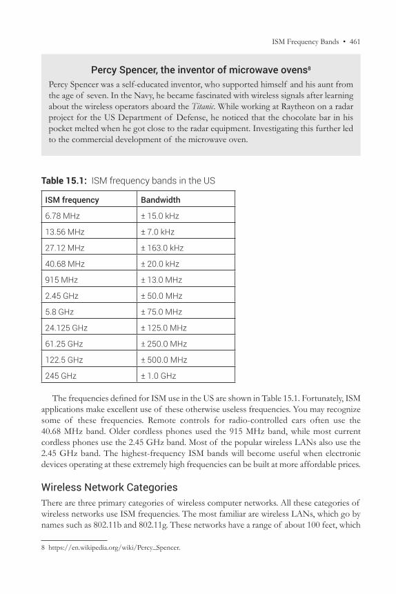
Table 15.1: ISM frequency bands in the US
ISM frequency Bandwidth
6.78 MHz ± 15.0 kHz
13.56 MHz ± 7.0 kHz
27.12 MHz ± 163.0 kHz
40.68 MHz ± 20.0 kHz
915 MHz ± 13.0 MHz
2.45 GHz ± 50.0 MHz
5.8 GHz ± 75.0 MHz
24.125 GHz ± 125.0 MHz
61.25 GHz ± 250.0 MHz
122.5 GHz ± 500.0 MHz
245 GHz ± 1.0 GHz
The frequencies defined for ISM use in the US are shown in Table 15.1. Fortunately, ISM applications make excellent use of these otherwise useless frequencies. You may recognize some of these frequencies. Remote controls for radio-controlled cars often use the 40.68 MHz band. Older cordless phones used the 915 MHz band, while most current cordless phones use the 2.45 GHz band. Most of the popular wireless LANs also use the 2.45 GHz band. The highest-frequency ISM bands will become useful when electronic devices operating at these extremely high frequencies can be built at more affordable prices.
Wireless Network CategoriesThere are three primary categories of wireless computer networks. All these categories of wireless networks use ISM frequencies. The most familiar are wireless LANs, which go by names such as 802.11b and 802.11g. These networks have a range of about 100 feet, which
8 https://en.wikipedia.org/wiki/Percy_Spencer.
462 • Supplementary Chapter 15 / Wireless
is enough to cover an average suburban home or small office. The second category of wireless networks is Bluetooth, which is called a personal-area network. This technology is used for connectivity within about 10 feet, which is ideal for connecting peripheral devices such as wireless keyboards and cameras in the immediate vicinity of a computer. Finally, we have an emerging category of wireless networks called metropolitan-area networks, which can provide coverage over a range of about 20 miles, enough to cover many metropolitan towns. In the rest of this chapter, we will look at the technologies and features of each of these categories of wireless networks.
Wireless Local-area Networks (the 802.11 series)Wireless local-area networks are the most familiar of the three categories of wireless networks. Most college campuses now have blanket wireless LAN coverage, and many college students use laptops with built-in wireless LAN capability to access the Internet. The technologies used in wireless LANs are specified in the 802.11 series of IEEE standards such as 802.11b, 802.11g, 802.11a, and 802.11n. Wireless LANs are often known as Wi-Fi.
Technologically, wireless LANs share many similarities with Ethernet, which is a wired network and was discussed in detail in the context of the data-link layer. For example, the frame structure of wireless LANs is almost identical to the frame structure of Ethernet. Also, wireless LANs use the 48-bit MAC addresses discussed with Ethernet.
There are, however, some important differences between Ethernet and wireless LANs. The most important difference is that wireless LANs have no defined boundaries. Wall jacks define the end-points for Ethernet. An Ethernet wall jack is hardwired to a specific port on a specific switch. As a result, a network administrator can control every aspect of the network traffic that flows through the wall jack and to the computer connected to the jack. When you connect to the network through a wall jack, you become part of a well-defined network. Typically one area of an office is served by one switch, and most users have no choice but to become a member of the Ethernet network that is closest to them.
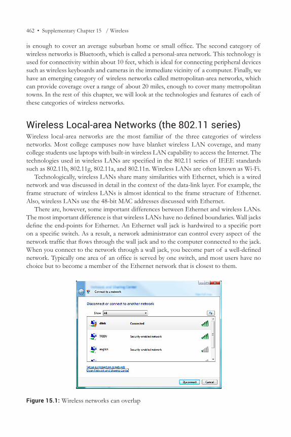
Figure 15.1: Wireless networks can overlap
Wireless Local-area Networks (the 802.11 series) • 463
On the other hand, wireless networks can overlap and they often do. At home, if you open up your “connect to network” dialog (right-click on the wireless icon in your system tray → connect to a network), you are likely to see wireless networks from many of your neighbors, as shown in Figure 15.1. If any of these wireless networks is not security enabled, you can use it to connect to the Internet. At the airport, you are likely to see overlapping wireless networks from the airport operator, Starbucks, mobile-phone companies, etc. Again, if any of these is not security enabled, you can use it to get Internet access.
Therefore, whereas geographical location uniquely defines network membership in Ethernet, it does not define network membership in wireless LANs. The technical implication is that, whereas the signal strength of a wired connection always meets Ethernet standards, the signal strength, and hence the network experience of a wireless connection, cannot be specified. The network performance of a wireless connection depends upon the distance of the host from the access point. A user who is very far from an access point will get very weak signals. To best serve users at different distances, wireless LAN standards specify different signal-modulation schemes for users at different distances from access points. Users who are close to an access point are served by faster-changing signals that can carry higher data rates but need strong signal strength for reliable detection. Users who are farther away from access points are served by signals that can only provide lower data rates but are easier to detect in the presence of noise. (You may be able to relate this to the discussion on signal detection, especially relating to signal reception in the presence of noise.)
Another difference between wireless LANs and wired LANs is that, whereas wired networks are extremely reliable, wireless is an inherently unreliable medium. Wireless networks are hurt by adverse weather, humidity, temperature, and other environmental conditions. As a result, the boundaries of a wireless network are not stable and keep shifting as environmental conditions change. Also, wireless networks are unprotected from competing signals from other devices such as cordless phones, walkie-talkies, fluorescent lamps, car ignitions, etc. By contrast, Ethernet cables do not carry any signals besides data, thus providing excellent signal-transmission properties.
Yet another difference concerns multiplexing. Ethernet does not use multiplexing because it uses all the available bandwidth in the medium to transmit signals. This is possible because Ethernet cables are not used for other applications. But wireless LANs share the bandwidth in the air with other users and have to send signals in specified signal bands. Therefore, wireless LANs use multiplexing. To use the available bandwidth efficiently, multiple channels have been defined within the 2.4 and 5.8 GHz bands. Since stations may be transmitting on any of these channels, wireless stations have to scan all the available channels to locate transmissions.
One last factor that makes wireless networks different from Ethernet is that, whereas all stations on an Ethernet can hear every transmission, stations at two opposite ends of a wireless LAN may not be able to hear each other. As a result, collision detection may be unsuccessful in wireless LANs. Wireless LANs therefore do not use CSMA/CD for medium-access control. Instead, wireless LANs use collision avoidance, and the medium-access control (MAC) mechanism used in wireless networks is called carrier sense multiple access with collision avoidance (CSMA/CA). What this means is that a waiting wireless station does not start transmitting immediately after a previous transmission ends. This is because the station knows that this is the time when other waiting stations are also likely
464 • Supplementary Chapter 15 / Wireless
to try to transmit and therefore the chances of a collision are highest at this time. Wireless stations wait for a certain time after a transmission ends before attempting to transmit data.
The primary implication of all these differences between wireless LANs and Ethernet is that wireless LANs require far greater error-detection capabilities than Ethernet. We will see that this is manifested in the physical layer of wireless LANs, which adds error protection over and above the CRC error detection introduced in Ethernet. This relates to the discussion about the physical layer and the impact of the transmission medium on data communication technologies. The primary challenge in wireless networks is the increased noise level. The technology response is to increase error protection in wireless LANs compared to Ethernet.
Wireless LAN ArchitectureLike Ethernet, wireless LANs are a data-link layer technology. Technology standards for both Ethernet and wireless LANs are defined by the 802 group at IEEE. The IEEE 802 group defines standards for local-area networks. As a result of this common origin, the frame structure of wireless LANs is almost identical to the frame structure of Ethernet. The differences between wireless and wired media discussed in the previous section are handled by differences in the physical layer. To account for the greater need for error detection in wireless media, the physical layer in wireless LANs adds header fields that help the receiver in error detection. We will see these fields later in this section.
To facilitate mobility, the designers of wireless LAN technologies planned wireless LANs in such a way that larger wireless LANs can be built from smaller wireless LANs. The smallest component unit of a wireless LAN is the area covered by a single access point. A wireless access point is a device that allows wireless hosts to connect to a wired network using wireless LAN technologies such as Wi-Fi. The area covered by an access point is called a basic service area (BSA). The basic service area and the access point covering that area together are called a basic service set (BSS).
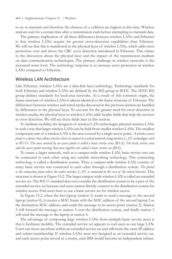
To create a larger network, such as a campus-wide wireless LAN, basic service sets can be connected to each other using any suitable networking technology. This connecting technology is called a distribution system. Thus, a campus-wide wireless LAN consists of many basic service sets connected to each other through a distribution system. The portal is the connection point where the entire wireless LAN is connected to the rest of the wired Internet. This structure is shown in Figure 15.2. The larger campus-wide wireless LAN is called an extended service set. The 802.11 standard does not consider the distribution system to be a part of the extended service set because end users cannot directly connect to the distribution system for wireless access. End users have to use a basic service set for wireless access.
In Figure 15.2, when the first laptop (station 1) wants to send a message to the second laptop (station 4), it creates a MAC frame with the MAC address of the second laptop 2 as the destination MAC address, and sends the message to its access point (station 2). Station 2 will forward the message to station 3 over the distribution system, and finally station 3 will send the message to the laptop at station 4.
The advantage of composing large wireless LANs from multiple basic service areas is that it facilitates mobility. The extended service set appears to end users as one large LAN. Users can move anywhere within an extended service set and still retain the same IP address and subnet membership. If wireless LANs were not designed as an extended service set, and each access point served as a router, each BSS would become an independent subnet.
Wireless Local-area Networks (the 802.11 series) • 465
Each time a user moved from one access point to the next, he would connect to a different subnet. This would potentially give him a different IP address and gateway router address. This address reallocation would stop any ongoing transfers and could also potentially disturb the network connectivity of some applications. With the concept of an extended service set, when users move from one access point to another, there is no change to any network setting, and ongoing network transfers can continue without interruption.
Within an organization, basic service sets may be placed as appropriate to deliver the required coverage and reliability. For example, in high-traffic areas, basic service sets may overlap to provide redundancy and to share traffic. If areas requiring network coverage are far from each other, basic service sets may be organized as in Figure 15.2, where they are separated from each other.
On one extended service set, a host needs to get associated with one access point through which it will send and receive messages. The distribution system uses this association information to deliver messages for a host to the correct access point.
The 802.11 standard does not specify how the distribution system should send messages between access points. Any local-area network technology can be used for the purpose. It is common for network administrators to use Ethernet for the distribution system.
The portal acts as the gateway between the extended service set and the rest of the Internet. When a message is sent to a host that is not in the extended service set, the distribution system sends the message to the portal. The portal performs all necessary packet format changes required for the message to be transported on the neighboring network. For example, in Figure 15.2, the portal transforms the outgoing message from the wireless 802.11 frame format to the 802.3 Ethernet frame format.
Figure 15.2: Structure of a campus-wide wireless LAN
466 • Supplementary Chapter 15 / Wireless
Most likely, your home network is built using one wireless router. This router acts as the access point as well as the portal. Depending upon the technologies used by your Internet service provider, this router may transform packets from 802.11 format to 802.3 format, or from 802.11 to the WAN frame format used by the ISP.
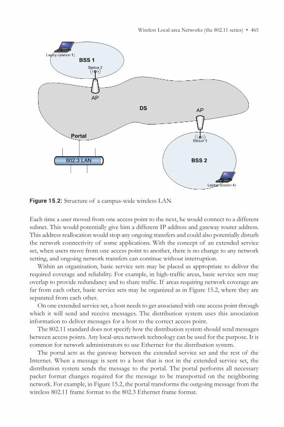
802.11 Frame MAC Layer Frame FormatThe general MAC layer frame format for wireless LANs is shown in Figure 15.3. You may note that it has many similarities with the Ethernet frame format. However, the wireless frame is more complex than Ethernet. Extra fields are necessary to identify the basic service set and access points, and to provide reliable transmission in the presence of noise. Also, most wireless LAN packets do not have all the fields in the general frame structure shown in Figure 15.3.
As in Ethernet, the wireless LAN frame format includes the source and destination MAC addresses, a frame check sequence, and data from the IP layer. These fields perform the same functions as in Ethernet—addressing, error detection, and data transfer. However, we see that wireless LANs also have some additional fields such as frame control, sequence control, QoS control, and duration/ID.
There are also four possible address fields (recall that Ethernet frames only have two address fields). We also see that the preamble and SFD fields of the Ethernet MAC frame are missing in the wireless LAN frame. The missing fields are the simplest to understand. These are moved to the physical layer header and retain their positions as the earliest fields of incoming frames. It is the additional MAC-header fields that are more complex to describe and to understand. These additional fields help in identifying the access points and in improving reliability. Their functions are described below:
Frame control This field describes attributes of the frame. For example, does the frame carry data, or does it report the status of the network? Is the frame going toward an AP? Is it being sent by an AP?
Duration/ID This field announces the expected amount of time required to transmit this frame. All listening stations will wait for this duration before attempting to send data.
Figure 15.3: 802.11 frame format
2 bytes2 bytes
6 bytes 6 bytes 6 bytes 2 bytes 6 bytes 2 bytes 4 bytes
0-2304 bytes
Direction of data flow
6 bytes6 bytes
Wireless Local-area Networks (the 802.11 series) • 467
Sending/receiving access-point addresses (address 1–address 4) Since wireless LAN packets need to pass through access points, the MAC addresses of the sending or receiving access points are added to the frame as required. Packets leaving an access point have the sending AP address, and packets sent to an AP have the receiving access point address.
QoS control This field specifies the desired type of service. The available types of service include best effort, voice, and video.
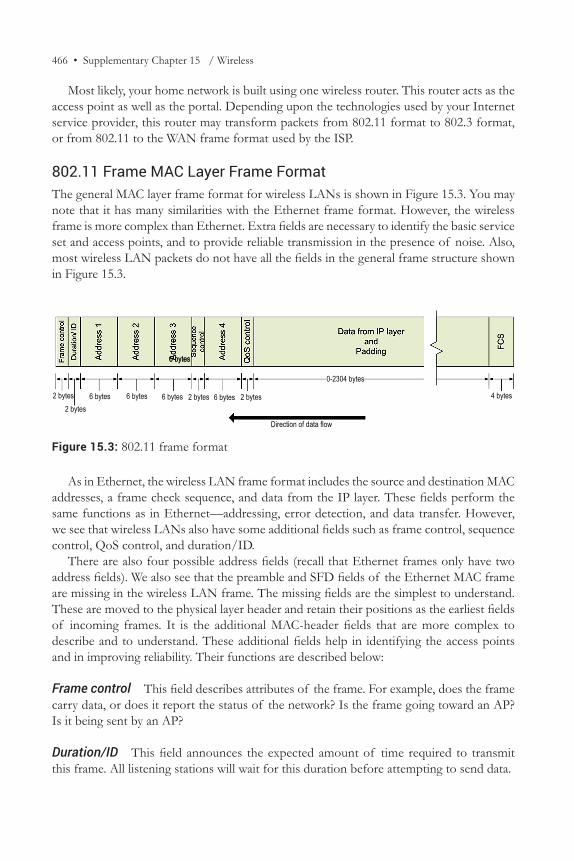
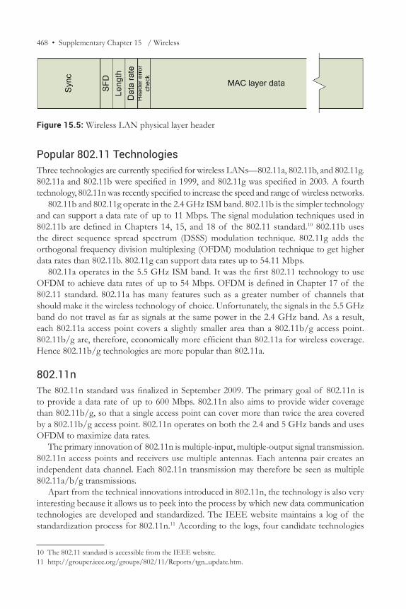
802.11 Frame Physical layer FormatRecall that the physical layer in Ethernet added no header fields to the frame. It simply converted the frame to a signal. However, the wireless LAN physical layer does add fields to the frame header. The wireless LAN physical layer header is shown in Figure 15.5. The primary function of the physical layer header is to add error protection to the frame header. It also specifies the data rate being used in the transmission.
Figure 15.4 shows the header fields in a captured wireless packet.9
9 At this point, it is highly recommended to check out the quick technical tutorial on 802.11 by Pablo Brenner, “A technical tutorial on the IEEE 802.11 protocol,” http://www.sss-mag.com/pdf/802_11tut.pdf (accessed Dec. 2015).
Figure 15.4: Header fields in a captured wireless frame
468 • Supplementary Chapter 15 / Wireless
Popular 802.11 TechnologiesThree technologies are currently specified for wireless LANs—802.11a, 802.11b, and 802.11g. 802.11a and 802.11b were specified in 1999, and 802.11g was specified in 2003. A fourth technology, 802.11n was recently specified to increase the speed and range of wireless networks.
802.11b and 802.11g operate in the 2.4 GHz ISM band. 802.11b is the simpler technology and can support a data rate of up to 11 Mbps. The signal modulation techniques used in 802.11b are defined in Chapters 14, 15, and 18 of the 802.11 standard.10 802.11b uses the direct sequence spread spectrum (DSSS) modulation technique. 802.11g adds the orthogonal frequency division multiplexing (OFDM) modulation technique to get higher data rates than 802.11b. 802.11g can support data rates up to 54.11 Mbps.
802.11a operates in the 5.5 GHz ISM band. It was the first 802.11 technology to use OFDM to achieve data rates of up to 54 Mbps. OFDM is defined in Chapter 17 of the 802.11 standard. 802.11a has many features such as a greater number of channels that should make it the wireless technology of choice. Unfortunately, the signals in the 5.5 GHz band do not travel as far as signals at the same power in the 2.4 GHz band. As a result, each 802.11a access point covers a slightly smaller area than a 802.11b/g access point. 802.11b/g are, therefore, economically more efficient than 802.11a for wireless coverage. Hence 802.11b/g technologies are more popular than 802.11a.
802.11nThe 802.11n standard was finalized in September 2009. The primary goal of 802.11n is to provide a data rate of up to 600 Mbps. 802.11n also aims to provide wider coverage than 802.11b/g, so that a single access point can cover more than twice the area covered by a 802.11b/g access point. 802.11n operates on both the 2.4 and 5 GHz bands and uses OFDM to maximize data rates.
The primary innovation of 802.11n is multiple-input, multiple-output signal transmission. 802.11n access points and receivers use multiple antennas. Each antenna pair creates an independent data channel. Each 802.11n transmission may therefore be seen as multiple 802.11a/b/g transmissions.
Apart from the technical innovations introduced in 802.11n, the technology is also very interesting because it allows us to peek into the process by which new data communication technologies are developed and standardized. The IEEE website maintains a log of the standardization process for 802.11n.11 According to the logs, four candidate technologies
10 The 802.11 standard is accessible from the IEEE website.11 http://grouper.ieee.org/groups/802/11/Reports/tgn_update.htm.
Figure 15.5: Wireless LAN physical layer header
Wireless Local-area Networks (the 802.11 series) • 469
were proposed for 802.11n in November 2004. The TGn technology that will be used in 802.11n obtained the required level of support from the standards committee in March 2007. In late 2008–early 2009, the technical and editorial issues in the standard were being fixed. Since technology vendors already knew most details of the 802.11n technology, and only editorial changes were expected in the standards document, draft 802.11n products became available in the market in 2008, even before the final standards document had been published.
802.11acThe 802.11ac standard was designed to improve upon 802.11n technologies to support transmission of multiple channels of HD video streams in homes and support many users per access point in enterprises. The standard was finalized in January 2014. 802.11ac achieves these higher data rate design objectives primarily by making three refinements to 802.11n: (1) moving from the 2.4 GHz band to the 5 GHz band; (2) refining technologies such as MIMO introduced with 802.11n; and (3) capitalizing on the improved sensitivity of affordable electronics by packing in more information over the same bandwidth.
Moving from the 2.4 GHz band to the 5 GHz band is one of the primary drivers of improved 802.11ac performance. You may recall from the discussion on the physical layer that data rates are directly proportional to bandwidth. The 2.4 Ghz band, used by 802.11n, includes frequencies in the range 2.4 GHz–2.5 GHz, for a total of 100 MHz. In conventional use, these are split into three non-overlapping channels of 22 MHz each. The 5 GHz band includes frequencies ranging from 5.15 GHz to 5.35 GHz, for a total of 200 MHz, or twice the bandwidth of the 2.4 GHz band. 802.11ac can split this band into two non-overlapping bands of 80 MHz each, providing almost four times the bandwidth per channel compared to 802.11n.
Multiple-input, multiple-output (MIMO) is a very recent development (in the 2000s) that allows transmitters to send multiple streams of data at the same frequency to the same receiver, but through different paths so that the conflicting signals never overlap. 802.11n allowed up to 4 MIMO paths, and 802.11ac allows up to 8 MIMO paths. By doubling the number of channels, where such MIMO benefits are possible, 802.11ac can provide twice the overall data capacity as 802.11n.
Finally, 802.11ac tries to talk faster than 802.11n (256 QAM instead of 64 QAM), packing more information over a single transmission than 802.11n.
The benefits of 802.11ac come with trade-offs. The total transmission power in ISM bands is regulated. When an 802.11ac transmitter uses the 80 MHz channel, the available power is distributed over four times the bandwidth compared to a 22 MHz channel. Reduced power means that the signal covers a shorter distance before it becomes indistinguishable from noise. Reduced power also means that the fast-talking technique (256 QAM) can only be used when the transmitter and receiver are in fairly close proximity (typically about 15 feet), and without any obstacles. To visualize this, imagine talking to a friend. As you try talking faster, your friend will have greater difficulty keeping up, and the same level of noise will be more disruptive than when you were speaking slowly.
For these reasons, 802.11ac is most useful in high-density areas such as lecture halls and cafeterias, where users can have a clear line-of-sight to the 802.11ac access point.
470 • Supplementary Chapter 15 / Wireless
These locations were very challenging to 802.11a/b/g technologies anyway because the 2.4 GHz band used by these technologies only supported three slower non-overlapping channels in a given space. By supporting two high-speed, non-overlapping channels in the same space, 802.11ac can allow network designers to serve high-density areas more conveniently.
Most data communication technologies go through this process of standardization. The standardization process begins with the recognition of a need. In the case of 802.11n and 802.11ac, it was the need for a high-speed, long-range wireless technology. A neutral standards-making body takes the lead in organizing an expert group to identify technical solutions that meet the need. In the case of 802.11, this body was the IEEE, which has led the standardization of all local-area network standards. Any interested persons from universities, technical companies, and even members of the public can become members of the group. The group develops proposals and votes on them until one technology solution receives overwhelming support. Finally, the technology is described in adequate detail in a standards document so that any interested vendor can use the standards document to create an implementation of the standard. The standardization process assures users that equipment they buy from one vendor will always be compatible with equipment sold by other vendors. In the case of 802.11, for example, you can buy a network interface card from Broadcom and be assured that it will work with access points sold by Linksys.
It is also hoped that the formal standardization process will lead to the adoption of the best possible technical solutions to meet requirements.
Personal-area Networks (the 802.15 series)The previous section described wireless local-area networks. These networks use an access point and provide high-speed connectivity to any hosts within a radius of about 100 feet. Hosts typically use wireless LANs for Internet access.
While wireless LANs are extremely useful, there are many connectivity applications where wireless access would be very useful but where Internet access is not necessary. An important example is replacing on desktops the short wires that are used for data transfer at low speeds, for example, to connect keyboards and mice to the desktop. This is where personal-area networks (PANs) come in. PANs, specified by the IEEE 802.15 standard, are designed to remove these wires that clutter desktops and make many devices cumbersome to use. Personal-area networks are computer networks designed for data transmission among devices in close proximity, typically owned by the same individual.
DLNAThe ubiquity of wireless LANs has created a strong desire among users to exchange content among home devices, for example, to stream music from smart phones to the home stereo, watch home security-camera footage on smart phones, etc. The digital living network alliance (DLNA) is an industry consortium aiming to achieve this interoperability.
Personal-area Networks (the 802.15 series) • 471
Personal-area networks like Bluetooth have been developed to provide communication over short distances, usually within 30 feet. This distance is sometimes called the personal operating space because people and devices within this range are usually in visual range. By limiting itself to this range, Bluetooth is designed to serve a small group of participating devices, usually carried by one person. Apart from keyboards and mice, other devices that use Bluetooth include cell phone headsets and digital cameras (to transfer pictures to computers).
The focus of Bluetooth is to develop extremely small, inexpensive, and low-power connectivity solutions. This makes it easy for electronics manufacturers to add Bluetooth capabilities to virtually any electronic device, even headsets and telephones, which are not traditionally considered computers. Since many of these devices are very small and can carry only a limited amount of battery power, power efficiency is an extremely important requirement for Bluetooth. Since signal transmission requires power, and more power is needed to send signals to greater distances, power efficiency concerns are the reason why Bluetooth devices have very short communication ranges.
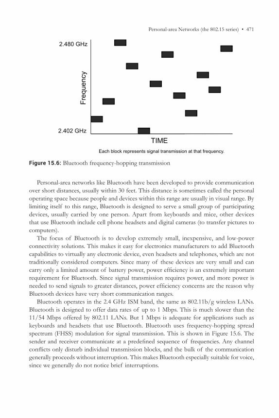
Bluetooth operates in the 2.4 GHz ISM band, the same as 802.11b/g wireless LANs. Bluetooth is designed to offer data rates of up to 1 Mbps. This is much slower than the 11/54 Mbps offered by 802.11 LANs. But 1 Mbps is adequate for applications such as keyboards and headsets that use Bluetooth. Bluetooth uses frequency-hopping spread spectrum (FHSS) modulation for signal transmission. This is shown in Figure 15.6. The sender and receiver communicate at a predefined sequence of frequencies. Any channel conflicts only disturb individual transmission blocks, and the bulk of the communication generally proceeds without interruption. This makes Bluetooth especially suitable for voice, since we generally do not notice brief interruptions.
Figure 15.6: Bluetooth frequency-hopping transmission
Each block represents signal transmission at that frequency.
TIME
2.480 GHz
2.402 GHz
Freq
uenc
y
472 • Supplementary Chapter 15 / Wireless
Though Bluetooth has some similarities with wireless LANs, there are some important distinctions between the two, such as:
1. Wireless LANs are largely used by computing devices such as laptops. Bluetooth is designed to be used by any electronic device to communicate with any other Bluetooth-capable electronic device.
2. Wireless LANs are typically used to obtain Internet connectivity. Bluetooth is typically used to connect to other nearby devices, for example a keyboard to a desktop, or a headset to a cell phone. As a result, while high data rate is a very important requirement for wireless LANs, it is less important for Bluetooth.
3. Wireless LANs require an infrastructure of access points. Bluetooth requires no such infrastructure. In fact, each Bluetooth device is capable of acting as a Bluetooth access point. Bluetooth devices automatically locate other Bluetooth devices in their vicinity.
4. Devices using wireless LANs are typically connected to power outlets and there are no special power-efficiency concerns in wireless LANs. Bluetooth devices are almost always driven by battery power and long battery life is an important concern for Bluetooth.
5. Finally, since Bluetooth is often used by devices that are relatively inexpensive, it is important for Bluetooth solutions to be extremely inexpensive, generally costing less than $10.
Swedish origins of the term “Bluetooth”The development of Bluetooth was initiated in 1994 by the Swedish mobile phone company Ericsson, to help laptops make calls using cell phones. The rather unusual name comes from King Harald “Bluetooth” Blaatand II of Denmark (940–981 a.d.). The nickname came from the king’s love for blueberries, which eventually stained his teeth. King Bluetooth unified Denmark and Norway during his reign. Ericsson hoped that the technology would similarly unite the communication and computing industries.12
Ericsson also created another well-known technology product in widespread use today—the MySQL database. The motivation was to create a small database engine to store contact information on cell phones.
Bluetooth ArchitectureThe basic unit of a Bluetooth network is the piconet. A piconet is a collection of devices connected to each other using Bluetooth. On the piconet, one master device connects with up to seven other active slave devices. A Bluetooth piconet serves a function similar to the basic service set (BSS) in 802.11 LANs. However, whereas an 802.11 BSS has a dedicated device called an access point that performs various management functions in the BSS, any device in a Bluetooth piconet can perform the management functions of a piconet. The device that
12 Elias M. Awad, Electronic Commerce: From Vision to Fulfillment, 3rd ed. (Pearson, 2007).
Personal-area Networks (the 802.15 series) • 473
performs this function is called the master. All other devices in the piconet are called slaves. The master provides a synchronization clock that helps all other devices in the piconet remain in sync with each other. Whereas a device may be a slave on multiple piconets at the same time, it can only be a master on one piconet at a time.
Many piconets may coexist in the same location. All the co-located piconets are called a scatternet. Think of a gathering of tech-savvy students in a classroom, with many students carrying Bluetooth-capable cell phones and music players. Each such student forms a piconet and the entire classroom becomes a scatternet. Devices connected to two different piconets in a scatternet do not have to route packets between the piconets.
Piconets are the personal-area equivalent of the basic service set. However, there are some major differences between basic service sets and piconets. The basic service set has a fixed location defined by the geographic area covered by the signals from the access point. The piconet, on the other hand, has no defined location. The piconet exists wherever the Bluetooth devices go. For example, the Bluetooth devices in a car form a piconet. As the car hurtles down the highway, the piconet moves along with it. Also, whereas the basic service set can support tens or even hundreds of devices, a piconet can connect at most eight devices.
To enable interference-free communication within co-located piconets, Bluetooth has mechanisms that enable each piconet to operate on a different physical channel. Recall from Chapter 2 that only one signal may be transmitted at a given frequency at a given location. Since all Bluetooth transmissions are in the 2.4 GHz ISM band, Bluetooth needs to create mechanisms whereby multiple transmissions can occur at the same frequency.
Bluetooth creates multiple communication channels at the same frequency by enabling devices to transmit at different time slots. Though only one device may transmit at a given time in a given location at a specified frequency, different devices may transmit at different time slots on the same frequency. Stations keep hopping from frequency to frequency in a systematic manner within the 2.4 GHz ISM band. This is called frequency hopping. Devices in each piconet use a different hopping sequence, thereby reducing chances of collisions. Finally, to maintain confidentiality, devices in each piconet use a different access code and header encoding to ensure that even if their signals are received by devices in other piconets, the data is unreadable.
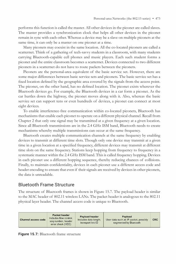
Bluetooth Frame StructureThe structure of Bluetooth frames is shown in Figure 15.7. The payload header is similar to the MAC header of 802.11 wireless LANs. The packet header is analogous to the 802.11 physical layer header. The channel access code is unique to Bluetooth.
Figure 15.7: Bluetooth frame structure
474 • Supplementary Chapter 15 / Wireless
You may note that the Bluetooth frame has some fields such as flow control, sequence number, and channel access code that are absent in wireless LANs. These fields help Bluetooth devices operate within a scatternet without interfering with each other. These fields also help Bluetooth provide reliable signal transmission for voice applications.
Bluetooth Device DiscoveryA very special capability of Bluetooth is device discovery. Two Bluetooth devices in close proximity to each other will automatically discover each other. If you have used a Bluetooth-enabled keyboard, you may have noticed this behavior when bringing the keyboard near your desktop. Your computer becomes aware of the presence of the keyboard and instantly pairs up with it. Device discovery makes Bluetooth extremely user-friendly and eliminates configuration-related problems for end users. The devices seem to become aware of each other as if by magic.
To enable device discovery, Bluetooth defines a special channel for inquiry requests and responses. Devices that are looking for nearby devices are called inquiring devices. Inquiring devices send out inquiry requests on the special inquiry channel. Devices willing to be found are called discoverable devices. Discoverable devices listen on the inquiry channel for inquiry requests and respond to these requests. Once the two devices become aware of each other, the inquiry procedure ends and the connection procedure begins.
In the connection procedure, one of the devices must be willing to receive a connection request from the other device. This device is called the connectable device. The connecting device sends a connection request to the connectable device on a connection channel specified by the connectable device. According to the Bluetooth standard, the device initiating the connection becomes the master for the connection.
If you think about it, you may notice that the Bluetooth device discovery and connection procedure is almost identical to the connection procedures used on social networks such as LinkedIn or Facebook. The websites act as the inquiry channel. Without websites such as Facebook or LinkedIn, you would not know where to search for your old friends. People willing to be found create profiles. People with profiles become discoverable. People searching for friends inquire of (search) the social-network site to see if their friend has a profile on the site. If the profile is found, the inquiry procedure is over.
Device discovery—LANs vs. PANsDevice discovery is not needed in wireless LANs because in most cases user intervention is necessary to determine the LAN to connect to. There are also security issues associated with wireless LAN membership, as a result of which, network administrators like to have control over the users who have access to the LAN. However, once a laptop successfully joins a wireless LAN, most laptops offer to join the network in the future without user intervention. Therefore, subsequent wireless LAN connections do operate in a manner similar to the device discovery procedure.
Personal-area Networks (the 802.15 series) • 475
Device discovery in other contexts—the MH 370 disaster13
This principle of requiring a discoverable device sending out a specific signal whose properties are known in advance is common across most contexts. A notable incident where this procedure received worldwide attention was associated with the discovery of the flight data recorder of the doomed flight MH 370, which vanished without a trace on March 8, 2014. Immediately following the accident, search efforts focused on detecting the signals emanating from the flight data recorders (black boxes) at 37.5 kHz. The black boxes are designed to send out this signal for 30 days at enough strength so they can be detected from a distance of up to a mile. Unfortunately, the devices could not be located within the appointed time, after which the batteries eventually would have died, ending the signal transmission.
For the connection procedure, you need to send a special connection-request message (friend request or invitation) to your friend. If the friend is connectable (responds favorably) and accepts your invitation, the two of you become connected.
WLAN and WPAN CoexistenceWireless LANs and Bluetooth operate at the same ISM band (2.45 GHz). Therefore, there is a high possibility that the signals from the two technologies may interfere with each other. Since Bluetooth is the more recent of the two technologies, it is only natural that the designers of Bluetooth had the responsibility of ensuring that Bluetooth minimized interference with the existing wireless LAN technology. Therefore, the Bluetooth standard defines two mechanisms to minimize interference between 802.11 and 802.15.
The first of these two mechanisms is collaborative and occurs where Bluetooth and 802.11 communicate with each other. This is possible when both 802.11 and 802.15 are present on one device, such as a laptop with both 802.11 and 802.15 capability. In the collaborative mechanism, Bluetooth avoids transmission during an ongoing 802.11 transmission. Alternately, Bluetooth transmits signals on a different channel than the channel on which the ongoing 802.11 communication is taking place.
The second mechanism is non-collaborative. The non-collaborative method is used when communication between 802.11 and 802.15 systems is not possible. For example, Bluetooth keyboards do not have 802.11 capability and the Bluetooth system on the keyboard has no way to collaborate with 802.11. In the non-collaborative method, the 802.15 system senses
13 https://en.wikipedia.org/wiki/Malaysia_Airlines_Flight_370.
NFCAnother technology for communication among proximate devices is called near-field communication (NFC). NFC is intended for communication among devices closer than 10 cm from each other. Example applications include smartphone payments and smartphone check-in.
476 • Supplementary Chapter 15 / Wireless
the medium before transmitting. It tries to find a channel in the 2.45 GHz ISM band that is not very busy and transmits signals on that channel.
Bluetooth CategoriesThe early Bluetooth specification supported data rates of up to 1 Mbps. However, as Bluetooth grew in popularity, newer applications for the technology were identified, each with slightly different requirements. As a result, additional categories of Bluetooth have been defined as subcategories of Bluetooth. The traditional Bluetooth specification is now called 802.15.1.
The first additional Bluetooth category supports higher data rates. It is useful to be able to transfer pictures from digital cameras to computers without the need to take out the picture card or connect the camera to the computer using a wire. Since digital images can get very large (a compressed picture from a 4-megapixel camera is about 1.5 MB), high data rates are very useful for image transfers. Accordingly, the high-data-rate Bluetooth specification, 802.15.3, supports data-transfer rates of up to 25 Mbps. This is accomplished by improving the efficiency at which the physical layer encodes data into signals, so that more data can be sent using the same bandwidth. Currently, higher data rates are becoming possible by integrating Wi-Fi with Bluetooth.
The second additional category of Bluetooth is for remote-control devices such as the remote controls for TVs, door openers, fans, lights, etc. These devices need very low data rates because, after all, the only data these remotes send is “ON” or “OFF” or “CHANNEL = 2.” However, we expect the batteries in remote controls to work for at least a couple of years. A unique feature of remote controls is that they are idle most of the time, used only for a few seconds in a day to operate remote devices. In almost every case, it is also true that the remote control does not need to be a connectable device. Only the controlled device, which usually is connected to a power outlet, needs to be connectable. To meet the requirements of remote controls, the 802.15.4 standard supports very low data rates, up to 250 Kbps. But to achieve long battery life, 802.15.4 devices are not in a connectable state (are switched off) when they are not being used. As a result, they do not lose power by scanning the medium, listening for other devices that may be interested in connecting to them.
802.16—Wireless Metropolitan-area NetworksThe final category of wireless networks operating in the ISM band is wireless metropolitan-area networks (MANs). A wireless metropolitan-area network (MAN) is a moderately high-speed computer network that usually spans a city or large enterprise campus. It is commonly used to interconnect LANs within its coverage area to each other and to the Internet.
Though these networks aren’t well known yet, wireless MANs are being pushed by leading computer manufacturers. The professional organization of the wireless MAN industry is called the Worldwide Interoperability for Microwave Access (WiMAX). Accordingly, wireless MANs are often known as WiMAX networks.
Wireless MANs have been standardized by the IEEE 802.16 group and, accordingly, these networks are also called IEEE 802.16 networks. The 802.16 network was initially designed to serve as an alternative to data connections by ISPs over cable and DSL.
802.16—Wireless Metropolitan-area Networks • 477
Since ISPs connect to homes from a central office to a fixed, wired router in the home, 802.16 was designed to provide connectivity between a fixed-base station (similar to cell phone towers) and stationary subscriber stations (similar to TV antennas at some homes). The technology was designed to support data rates exceeding 20 Mbps to a range of up to 10 miles. With the evolution of technology, in 2005 support for mobile stations was added to WiMAX as 802.16e. This is a very promising development because 802.16 networks can now be used to create wireless “metro zones” to cover large cities and provide metro-wide mobile Internet access. Broadband wireless access could be made available to mobile users anywhere within the “metro zone,” just as 802.11 enables wireless access in a BSS.
Most efforts to create city-wide LANs using 802.11 technologies have failed due to the high costs of maintaining the large number of 802.11 access points required to provide city-wide coverage. 802.16 will enable wireless coverage over the same area using just one base station. Perhaps 802.16 will enable the vision of city-wide LANs after all.
In some developing countries, WiMAX has been used successfully to provide phone connectivity to far-flung rural areas. Pulling a wire from a phone company central office to a remote rural switch is extremely expensive. Instead, WiMAX can be used to wirelessly connect a small rural phone switch to the central office. Homes can be connected to the switch using the traditional twisted pair. These links are affordable because they are short.
In a typical data-communication application, 802.16 provides data rates up to 40 Mbps per channel to stations as far as six miles away from a base station. A very popular data rate for small businesses is 1.5 Mbps. 802.16 data rates are sufficient to support hundreds of such small businesses from a single base station. Alternately, each 802.16 base station can be used to support thousands of homes with high-speed Internet access.
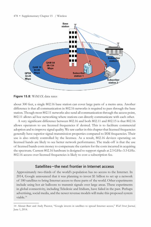
802.16 Data RatesFigure 15.8 shows the theoretical data rates supported by 802.16 as a function of distance. It also shows the modulation techniques used to achieve the data rates. As expected, stations close to the base station can receive the highest data rates (up to 134 Mbps). As the station gets farther away, the data rates fall to 90 Mbps. The farthest stations can expect data rates of up to 45 Mbps. These are theoretical data rates; actual data rates may be lower. Stations closer to the base station use quadrature amplitude modulation (QAM) and farther stations use quadrature phase shift keying. You may recall that amplitude modulation generally supports high data rates but is very susceptible to noise. It is therefore suitable near the base station where signals are strong. Phase modulation offers high immunity to noise but at the expense of slower data rates using the same bandwidth. It is useful at longer distances.
802.16 vs. 802.11802.16 networks are likely to be used in a similar manner as 802.11 networks—to obtain Internet connectivity on mobile laptops. The two technologies also share other similarities. Both are standardized by the IEEE. Both use ISM frequency bands. 802.11 uses the 2.4 GHz and 5.5 GHz bands; 802.16 networks can use either of these bands.
In spite of these similarities, there are some significant differences between 802.11 and 802.16. The primary difference is that, whereas 802.11 access points cover only a radius of
478 • Supplementary Chapter 15 / Wireless
about 300 feet, a single 802.16 base station can cover large parts of a metro area. Another difference is that all communication in 802.16 networks is required to pass through the base station. Though most 802.11 networks also send all communication through the access point, 802.11 allows ad hoc networking where stations can directly communicate with each other.
A very significant difference between 802.16 and both 802.11 and 802.15 is that 802.16 allows operators to use licensed frequencies if desired. This is to facilitate commercial adoption and to improve signal quality. We saw earlier in this chapter that licensed frequencies generally have superior signal-transmission properties compared to ISM frequencies. Their use is also strictly controlled by the licensee. As a result, 802.16 devices operating on licensed bands are likely to see better network performance. The trade-off is that the use of licensed bands costs money to compensate the carriers for the costs incurred in acquiring the spectrum. Current 802.16 hardware is designed to support signals at 2.5 GHz–3.5 GHz. 802.16 access over licensed frequencies is likely to cost a subscription fee.
Satellites—the next frontier in Internet accessApproximately two-thirds of the world’s population has no access to the Internet. In 2014, Google announced that it was planning to invest $1 billion to set up a network of 180 satellites to bring Internet access to these parts of the world. Other experiments include using hot air balloons to transmit signals over large areas. These experiments in global connectivity, including Teledesic and Iridium, have failed in the past. Perhaps advertising, social media, and the newer revenue models will make this proposed system viable.14
14 Alistair Barr and Andy Pasztor, “Google invests in satellites to spread Internet access,” Wall Street Journal, June 1, 2014.
Figure 15.8: WiMAX data rates
Example Case—The Oil Industry • 479
EXAMPLE CASE—The Oil IndustryWhen gas prices rose rapidly in recent years, oil companies earned record profits during 2007–2008. When the economy slowed down in late 2008, oil companies experienced slumping demand for the first time in years. Improved supply-chain management using computer networks is helping oil companies deal with these boom-and-bust cycles and also to lower oil prices.
Integrated petroleum firms are some of the largest companies in the world. The industry had sales of $1.99 trillion in 2008, comparable to US government tax revenues of $2.54 trillion in 2008. The industry is very volatile, however, with estimated net sales in 2009 of $1.28 trillion—a drop of more than 35% compared to 2008, due to falling prices and reduced demand resulting from weaknesses in the economy. The industry also has very low profit margins, with net margins of only 8.1% in 2008. With political sensitivities and customer behavior limiting price increases, the way to improve profitability in the industry is to lower costs.
We saw in the Wal-Mart case that utilizing point-of-sale data to optimize distribution and manufacturing can eliminate inventory accumulation, reduce waste, and lower costs. In most industries, this requires information sharing between many companies that complete the supply chain. But the petroleum industry has a unique advantage. It is probably the only industry still dominated by vertically integrated firms. Vertical integration refers to a single firm controlling all aspects of a product’s manufacture, from raw materials to distribution. The major oil companies such as Exxon-Mobil, British Petroleum, Shell, and Chevron own or control all factors of production starting from the oil fields where oil is drilled from the ground to the gas stations where drivers fill their cars.
Whereas retailers such as Wal-Mart have to work out legal and technical barriers to protect their intellectual property from being stolen by business partners with whom they share information, vertically integrated oil companies have a unique advantage. With the right systems, they can share point-of-sale data from company-owned gas stations all the way up the supply chain to company-owned or company-controlled oil rigs and refineries, thereby optimizing drilling, distribution, and storage to lower costs. Publicly available information indicates that Chevron is a leader in its industry.
A large distribution company such as Chevron has a number of places where unnecessary costs can add up. For safety reasons, containers such as oil tankers and trucks do not deliver unless they can be emptied fully. Ships waiting for storage space to accept their crude can pay port charges as high as $30,000 per day. Delivery charges for a truckload of gas can be as high as $150. If a truck returns because the gas station is not empty enough to receive the entire load of fuel (retain), the company incurs an unnecessary expense. On the other hand, if the gas station is out of fuel when a customer arrives (run-out), Chevron could lose the customer and earn a bad reputation.
Chevron uses wireless and satellite networks in many parts of the company to manage its supply chain. Many of its gas stations are linked by a satellite network to a central dispatch center. These stations have electronic level monitors in the underground gas tanks to monitor fuel levels in real time. A wired network in the gas station transports the data to the satellite dish on top of the station from where the data is sent to the dispatch station. Using this real-time data, the dispatch station is able to optimally schedule fuel deliveries
480 • Supplementary Chapter 15 / Wireless
from terminals located on the outskirts of major metros, minimizing unsuccessful deliveries (retains) and stock-outs (run-outs). Chevron can also use the computer network to monitor fuel levels in the terminal tanks to schedule oil tanker deliveries so that tankers do not have to wait at ports to make deliveries.
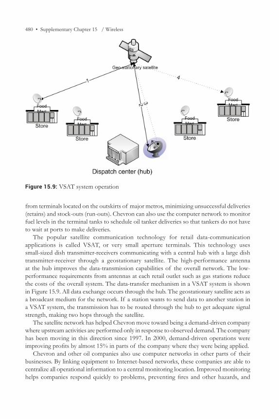
The popular satellite communication technology for retail data-communication applications is called VSAT, or very small aperture terminals. This technology uses small-sized dish transmitter-receivers communicating with a central hub with a large dish transmitter-receiver through a geostationary satellite. The high-performance antenna at the hub improves the data-transmission capabilities of the overall network. The low-performance requirements from antennas at each retail outlet such as gas stations reduce the costs of the overall system. The data-transfer mechanism in a VSAT system is shown in Figure 15.9. All data exchange occurs through the hub. The geostationary satellite acts as a broadcast medium for the network. If a station wants to send data to another station in a VSAT system, the transmission has to be routed through the hub to get adequate signal strength, making two hops through the satellite.
The satellite network has helped Chevron move toward being a demand-driven company where upstream activities are performed only in response to observed demand. The company has been moving in this direction since 1997. In 2000, demand-driven operations were improving profits by almost 15% in parts of the company where they were being applied.
Chevron and other oil companies also use computer networks in other parts of their businesses. By linking equipment to Internet-based networks, these companies are able to centralize all operational information to a central monitoring location. Improved monitoring helps companies respond quickly to problems, preventing fires and other hazards, and
Figure 15.9: VSAT system operation
References • 481
improving the uptime of pipelines and storage tanks. Industry experts believe that the benefit from these efforts is equivalent to adding 2% to 5% refining capacity.
Wireless networks are particularly useful to Chevron in its drilling operations. As new oilfields are becoming difficult to find, oil companies are focused on improving the productivity of existing oil fields. Installing wireless sensors on pumps and other equipment allows operators to access maintenance data on all equipment in a location directly from their trucks, significantly improving their productivity. Equipment defects that may have gone undetected for months can now be attended to in days.
At remote oil fields, Chevron has used a type of wireless network called a “mesh” network to monitor its oil wells. Unlike traditional 802.11 networks where dedicated devices act as base stations and routers, in mesh networks each field device acts as both a sensor and a wireless router. By placing devices suitably close to each other, each device in a mesh network requires very little power because the radio signal from the device has to travel only a short distance to the nearby node. The devices can also be designed to transmit only when needed, further reducing power requirements and allowing sensor batteries to last for up to seven years. For many sensor-deployment projects, wiring costs can be up to 75% of the cost of the project. Wireless technologies can eliminate this huge cost.
References 1. Davis, A. “Job Losses Cut into U.S. Driving.” Wall Street Journal, Jan. 2, 2010, A3. 2. Malik, N.S. “Refiners Keep Tab with Real-Time Monitoring.” Wall Street Journal,
Dec. 23, 2009, B2. 3. Mir, R.M. “Satellite Data Networks.” http://www.cse.wustl.edu/~jain/cis788-97/ftp/
satellite_data.pdf (accessed Apr. 9, 2016). 4. Pister, K., and G. LaFramboise. “Wired Warriors.” www.isa.org. 5. Value Line, Industry Report. “Integrated Petroleum Firms.” 6. Worthen, B. “Drilling for Every Drop of Value.” CIO, June 1, 2002.
SummaryWireless networks enable mobility and have become extremely popular in homes and businesses. Wireless networks enable inexpensive Internet access in many homes and offices. Most wireless networking technologies use ISM frequency bands. Frequencies in these bands can be used without cost or licensing restrictions. To meet the requirements of different applications that benefit from wireless access, three different categories of wireless technologies have been defined.
The best-known wireless technology is the 802.11 wireless LAN technology, sometimes also called Wi-Fi. Wireless LANs use access points to provide high-speed Internet access within a range of about 300 feet from the access point. Multiple access points can be connected using a distribution system to provide wireless LAN coverage over an arbitrarily large area. There are three wireless LAN standards popular today: 802.11a, 802.11b, and 802.11g. 802.11 technologies can provide network connection speeds of up to 54 Mbps.
482 • Supplementary Chapter 15 / Wireless
The newest wireless LAN technology, 802.11n, is expected to provide data rates of up to 600 Mbps.
The second category of wireless networks is personal-area networks, better known as Bluetooth. These are standardized by the IEEE as 802.15 networks. Bluetooth provides data rates of up to 1 Mbps within a radius of about 30 feet. Bluetooth helps eliminate wire clutter created by peripheral devices such as keyboards and mice. The primary design goal of Bluetooth is to provide adequate data connectivity while maximizing battery life and minimizing costs.
The last category of wireless networks is IEEE 802.16 wireless metropolitan-area networks, also known as WiMAX. These networks can substitute for cable and DSL connections and provide high-speed connectivity to fixed receivers at large distances. Mobile functionality has recently been added to WiMAX. WiMAX is likely to be offered as a paid service in many metro areas in the coming years.
About the ColophonThe line in the colophon was uttered by the fox to the little prince in French aviator Antoine de Saint-Exupéry’s most famous novella, The Little Prince. The novella is believed to have been inspired by the aviator’s real-life experiences in the Sahara desert. It is one of the best-selling books ever—80 million copies—and has been translated into more than 180 languages. Though written and illustrated for children, the book makes many thoughtful observations about life. One of the best known of these is “On ne voit bien qu’avec le cœur. L’essentiel est invisible pour les yeux,” which translates as, “It is only with the heart that one can see rightly. What is essential is invisible to the eye.”
Computers and networks have no heart. At the heart of their operations though, are properties of the universe that are invisible to the eye. Computer networks do not need a visible medium to transport data. The properties required from nature to support signal transmission are invisible to the naked eye. The invisible outer space can transport data just as effectively as visible wired networks. In an earlier age, this ability of the universe to carry electronic signals was given a name—ether.
REVIEW QUESTIONS 1. What are wireless networks? Why are they useful? 2. Some cities took up projects to set up wireless LANs all over the city. Read about the
project taken up by one such city. Was the project a success? Why or why not? 3. What are some of the concerns with using wireless networks? 4. What are ISM frequency bands? Why are they useful? 5. What are some differences between wired and wireless LANs? How do they impact
the design of the wireless LAN header? 6. What is a basic service set? A basic service area? 7. What is an access point? What are some reasons why you would prefer access points to
wireless routers when creating a wireless network in your organization? 8. What is a distribution system in wireless LANs? 9. What is an extended service set?
Example Case Questions • 483
10. What is a portal in a wireless LAN?11. What are some differences between the physical layers in wireless and wired LANs?12. What are the common wireless LAN categories? What are the important differences
between them?13. What is 802.11n? What are some likely advantages of 802.11n over the traditional
wireless LANs? How does 802.11n obtain these advantages?14. What are personal area networks? How are they different from LANs?15. What are some important characteristics of Bluetooth?16. What is a piconet? What are some differences between a piconet and a basic service set?17. What are master and slave devices in a piconet?18. What is a scatternet?19. What are some advantages of having distinct physical channels in Bluetooth?20. Why is device discovery useful in Bluetooth? How is device discovery accomplished?
Why is device discovery not needed in wireless LANs?21. Describe the mechanisms that have been defined for WLANs and WPANs to coexist
at the same frequency bands without interfering with each other.22. What are the different categories of Bluetooth? What are they used for?23. What are wireless MANs? What are their primary uses?24. What data rates and ranges are likely to be available on wireless MANs?25. What are the differences between wireless LANs and wireless MANs?
EXAMPLE CASE QUESTIONS 1. What are the different kinds of wireless data communication technologies used in the
case? 2. What is a retain in the context of supply chains? 3. What is a run-out in the context of supply chains? 4. What is a mesh network in the context of wireless sensor networks? What are its
advantages and disadvantages? (Wikipedia is a good resource.) 5. Why do companies with a nationwide footprint often use satellite-based data networks
for data transmission instead of wired networks such as DSL? 6. A leading provider of satellite-based data communication services is DirecPC. Visit the
company’s website and write a short (one-paragraph) report on the services offered by the company based on information provided at the website. Include information such as data rates, plan prices, and other information relevant to new subscribers.
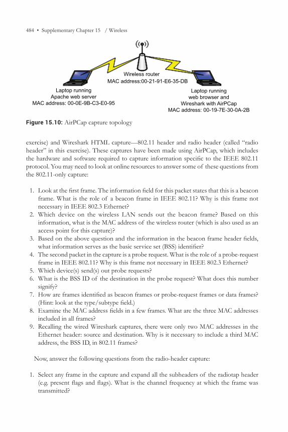
HANDS-ON EXERCISE—AirPCap Wireshark CapturesYou have used Wireshark to capture packets on your local computer. In this exercise, you will use two Wireshark captures on the wireless interface to visualize the operation of IEEE 802.11 networks. Both captures show the download of a web page over a wireless LAN. The network topology of the setup for the capture is shown in Figure 15.10.
The two captures are included in the readings for this chapter on the companion website—Wireshark HTML capture—802.11-header only (called “802.11 only” in this
484 • Supplementary Chapter 15 / Wireless
exercise) and Wireshark HTML capture—802.11 header and radio header (called “radio header” in this exercise). These captures have been made using AirPCap, which includes the hardware and software required to capture information specific to the IEEE 802.11 protocol. You may need to look at online resources to answer some of these questions from the 802.11-only capture:
1. Look at the first frame. The information field for this packet states that this is a beacon frame. What is the role of a beacon frame in IEEE 802.11? Why is this frame not necessary in IEEE 802.3 Ethernet?
2. Which device on the wireless LAN sends out the beacon frame? Based on this information, what is the MAC address of the wireless router (which is also used as an access point for this capture)?
3. Based on the above question and the information in the beacon frame header fields, what information serves as the basic service set (BSS) identifier?
4. The second packet in the capture is a probe request. What is the role of a probe-request frame in IEEE 802.11? Why is this frame not necessary in IEEE 802.3 Ethernet?
5. Which device(s) send(s) out probe requests? 6. What is the BSS ID of the destination in the probe request? What does this number
signify? 7. How are frames identified as beacon frames or probe-request frames or data frames?
(Hint: look at the type/subtype field.) 8. Examine the MAC address fields in a few frames. What are the three MAC addresses
included in all frames? 9. Recalling the wired Wireshark captures, there were only two MAC addresses in the
Ethernet header: source and destination. Why is it necessary to include a third MAC address, the BSS ID, in 802.11 frames?
Now, answer the following questions from the radio-header capture:
1. Select any frame in the capture and expand all the subheaders of the radiotap header (e.g. present flags and flags). What is the channel frequency at which the frame was transmitted?
Figure 15.10: AirPCap capture topology
Wireless routerMAC address:00-21-91-E6-35-DB
Laptop runningweb browser and
Wireshark with AirPCapMAC address: 00-19-7E-30-0A-2B
Laptop runningApache web server
MAC address: 00-0E-9B-C3-E0-95
Critical-Thinking Exercise—Ubiquitous Wi-Fi • 485
2. Briefly describe the channels used by 802.11b/g. 3. Why is channel 6 one of the recommended channels for transmitting 802.11 wireless
LAN data? 4. Was the frame transmitted using FHSS (Frequency Hopping Spread Spectrum) or
OFDM (Orthogonal Frequency Division Multiplexing)?
CRITICAL-THINKING EXERCISE—Ubiquitous Wi-Fi 1. Technologies such as 802.11ac are bringing wireline speeds to Wi-Fi. Do you think
Wi-Fi will eliminate the need for wired LANs within the next decade? Why or why not?
IT INFRASTRUCTURE DESIGN EXERCISE—Add Wi-FiThe employees at the Amsterdam service center use laptops for work and need wireless coverage throughout the two floors of the building. The company has therefore decided to install a wireless LAN at this location. (In general, the company will also create an additional subnet for this wireless network, but you can ignore this detail for this class.)
Answer the following questions:
1. What wireless technology would you recommend to create the wireless LAN—IEEE802.11a, IEEE802.11b, IEEE803.11g, or IEEE802.11n? Justify your choice.
2. Assume that both floors of the building have the same dimensions. Making typical assumptions about the needed work space for each employee, what is the total area in the building that needs wireless coverage?
3. Given your technology choice and the area calculated above, how many access points would you need to provide satisfactory coverage, where needed, on both floors?
4. Update your network diagram to include the portal for the wireless network in Amsterdam.
_____________________________________________________________________
Chapters 15 and 16 are online supplements to Business Data Communications and IT Infrastructures, 2nd Edition, by Manish Agrawal & Rekha Sharma. © 2017, Prospect Press

487
S U P P L E M E N T A R Y C H A P T E R 1 6
Phone Networks
Mr. Watson—come here—I want to see you.
Alexander Graham Bell
OverviewThe earlier chapters have focused on the technologies that enable the Internet. However, a large volume of information exchange occurs over a more humble technology—the telephone. Toward the end of the 20th century, phone networks also served as the precursors of modern WAN networks. In recent years, the telephone has evolved with the introduction of cell phones, which add mobility to phone technology. Given the importance of the technology for modern businesses, it is useful to know about the technologies that underlie land and cellular phone networks. At the end of this chapter you should know about:
• the architecture and components of landline phone networks• the signals used in phone networks• DSL—an early technology developed by phone companies to offer high-speed
Internet access• the architecture and components of cellular networks• the evolution of cell phone networks• code division multiple access—the signaling scheme used in modern cell phone
networks
IntroductionPhone networks served as the early access mechanism for the Internet. In the 1990s, as Internet service providers such as AOL were perfecting their business models and technologies (recall the reference to AOL’s growth), the phone network served as the medium over which most residents obtained their Internet connections. Only in the early years of the 21st century have carriers installed dedicated networks for Internet service. It is therefore useful to have a high-level understanding of the architecture of phone networks.
The phone network is best seen as an analog information-transmission system. Signals are not digitized or packetized by landline phones. Instead, signals are simply allowed to flow
488 • Supplementary Chapter 16 / Phone Networks
over the wires in the same form in which they are generated at the source. In this chapter, we will look at the components of the phone system, and some significant events that helped the phone system evolve to its current form.
The data communication timeline shows that for more than 100 years (1840–1969), the only technologies available for long-distance information exchange were the telegraph and the telephone. Of the two, the telephone continues to be widely used globally. The basic technology underlying the phone system is quite simple. When a user dials a phone number, the switches in the phone network establish a dedicated circuit from the sender to the receiver so that signals can flow uninterrupted between the sender and the receiver. As long as the call is in progress, the network resources allocated to the call are unavailable to other callers. This mechanism of connecting users is called circuit switching. Circuit switching is a process that, on demand, connects two or more communicating devices and permits the exclusive use of a data circuit between them until the connection is released.
Once the circuit is established, a microphone in the handset converts the talker’s voice to electronic signals. These signals are carried over the phone network from the sender to the receiver. A speaker in the receiver handset converts these signals to voice that is heard by the receiver.
Since the phone technology is so simple, particularly compared to the more complex packet-switched technologies used on the Internet, the phone network is sometimes also called plain old telephone service (POTS), with the term “plain old” implying that the phone is a plain vanilla kind of service. However, such descriptions should not lead us to underestimate the importance of phone service. Though the phone technology is quite simple, it is one of the most important technologies for businesses. Figure 16.1 shows the levels of adoption of landline phones in different parts of the world.1 As seen in the figure, over the last decade, landline adoption has been relatively steady around the world. Assuming three inhabitants per family, there would be approximately 35 families for every 100 inhabitants (100/3) and with about 50 phones for every 35 families, the figure shows that on average, there is more than one phone line per family in the developed world.2
Phone Network ComponentsThe phone network is called the public-switched telephone network (PSTN). For basic understanding, the components of the network are shown in Figure 16.2. The PSTN terminates on the walls of end-user homes and offices. Customers maintain the phone
1 www.itu.int/ITU-D/ict/statistics/ict/2 Since the statistics also include business phones, it is fair to say that most homes in the developed world have a landline phone connection.
Why didn’t the telephone pass eighth grade?Because it wasn’t a “Smart Phone.”
Source: Boys’ Life magazine, July 2012
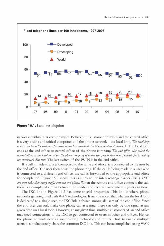
Phone Network Components • 489
networks within their own premises. Between the customer premises and the central office is a very visible and critical component of the phone network—the local loop. The local loop is a circuit from the customer premises to the last switch of the phone company’s network. The local loop ends at the end office or central office of the phone company. The end office, also called the central office, is the location where the phone company operates equipment that is responsible for providing the customer’s dial tone. The last switch of the PSTN is in the end office.
If a call is made to a user connected to the same end office, it is connected to the user by the end office. The user then hears the phone ring. If the call is being made to a user who is connected to a different end office, the call is forwarded to the appropriate end office for completion. Figure 16.2 shows this as a link to the interexchange carrier (IXC). IXCs are networks that carry traffic between end offices. When the remote end office connects the call, there is a completed circuit between the sender and receiver over which signals can flow.
The IXC link in Figure 16.2 has some special properties. This link is where phone networks get integrated with WAN technologies. It may be noted that whereas the local loop is dedicated to a single user, the IXC link is shared among all users of the end office. Since the end user can only make one phone call at a time, there can only be one signal at any given time on a local loop. However, at any given time, multiple customers of an end office may need connections to the IXC to get connected to users in other end offices. Hence, the phone network needs a multiplexing technology in the IXC link to enable multiple users to simultaneously share the common IXC link. This can be accomplished using WAN
Figure 16.1: Landline adoption
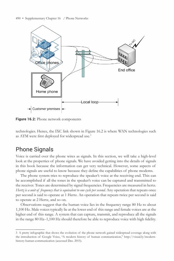
490 • Supplementary Chapter 16 / Phone Networks
technologies. Hence, the IXC link shown in Figure 16.2 is where WAN technologies such as ATM were first deployed for widespread use.3
Phone SignalsVoice is carried over the phone wires as signals. In this section, we will take a high-level look at the properties of phone signals. We have avoided getting into the details of signals in this book because the information can get very technical. However, some aspects of phone signals are useful to know because they define the capabilities of phone modems.
The phone system tries to reproduce the speaker’s voice at the receiving end. This can be accomplished if all the tones in the speaker’s voice can be captured and transmitted to the receiver. Tones are determined by signal frequencies. Frequencies are measured in hertz. Hertz is a unit of frequency that is equivalent to one cycle per second. Any operation that repeats once per second is said to operate at 1 Hertz. An operation that repeats twice per second is said to operate at 2 Hertz, and so on.
Observations suggest that the human voice lies in the frequency range 80 Hz to about 1,100 Hz. Male voices typically lie at the lower end of this range and female voices are at the higher end of this range. A system that can capture, transmit, and reproduce all the signals in the range 80 Hz–1,100 Hz should therefore be able to reproduce voice with high fidelity.
3 A pretty infographic that shows the evolution of the phone network gained widespread coverage along with the introduction of Google Voice, “A modern history of human communication,” http://visual.ly/modern- history-human-communication (accessed Dec. 2015).
Figure 16.2: Phone network components
Legal Developments • 491
The phone system has been designed to transmit signals in the 300 Hz–3,400 Hz range. Since 3,400 is greater than 1,100, the high end of the range captures all human voice at high frequencies. However, the cutoff at the low end, at 300 Hz, causes some loss of information. So, why does the phone system not capture the signals in the frequency range 80 Hz–300 Hz? Why are we willing to lose the information in these frequencies? The reason to eliminate lower-frequency signals is that the power line transmits power at 60 Hz. Filtering away signals below 300 Hz eliminates the strong hum that is likely to be created in the phone receiver by the power line and its harmonics. Transmitting signals within the frequency band of 300 Hz–3,400 Hz has been found to be adequate to convey the human voice over the telephone. While this does not create a high-fidelity (hi-fi) reproduction of the sender’s voice, the sender’s voice is clearly recognizable over the phone network.
The phone system only needs to transmit a signal within a relatively narrow bandwidth of about 3 kHz (3,400 Hz - 300 Hz = 3,100 Hz). The transmission of phone signals does not require a very high quality of wire in the local loop. As a result, the phone network was built using relatively inexpensive copper cables (inferior in quality even to Cat3 cables) in the local loop. This kept costs low and served the phone network well throughout the 20th century. By comparison, Ethernet signals require thousands of times the bandwidth for signal transmission. When customers began to demand broadband connections in the last decade of the 20th century, the poor signal-carrying properties of Cat3 phone cables in the local loop became a stumbling block for phone companies. Serving high data rates requires transmission of high-bandwidth signals, something the local loop could not do. To overcome this limitation, phone companies could either invest in a new local loop or figure out a way to do the best they could with the existing local loop. Phone companies therefore developed DSL, a technology that allowed high-data-rate signals to be carried over phone lines for short distances.
Legal DevelopmentsThe evolution of the phone network in the United States has been influenced not just by competitive forces, but also by legal action taken by the government.4 Alexander Graham Bell had created AT&T to commercialize his invention of the telephone. Over the years, AT&T invested in creating a nationwide telephone network. Many residents were located in remote areas. Even though it was very expensive to connect these users to the telephone network, AT&T provided these customers with phone service at the same rates as urban customers. To facilitate these investments, in the early years of the 20th century, the US government allowed AT&T to operate as a regulated monopoly. The monopoly status guaranteed the company suitable returns on its investments in developing a national network that provided phone service to all residents in the United States. This was a lot like the way most states allow gas and electric utilities to operate as regulated monopolies. The utilities agree to invest in providing services to all residents, however inaccessible they might be.
4 For a very informative graphic that shows the evolution of the phone network in the United States, from Graham Bell to the contemporary cell phone providers, please see the graphic, “A tangled family tree,” Wall Street Journal, Mar. 29, 2011, http://www.wsj.com/articles/SB10001424052748704471904576229250860034510 (accessed Feb. 2016).
492 • Supplementary Chapter 16 / Phone Networks
In return, the state protects them from competition (monopoly) and allows them to earn reasonable (regulated) profits.
1984—Competition in Long-distance Phone Service and the Modified Final JudgmentBy the mid 1970s, technological innovations had led to the emergence of a number of competitors providing long-distance phone service. There was no longer any need to provide monopoly protection to AT&T in long-distance phone service. To level the playing field for competitors in the long-distance phone business, the US government filed an anti-trust lawsuit against AT&T in 1974. The lawsuit ended in 1982 when AT&T and the US government agreed on the terms of a solution to enable competition in long-distance phone service. As part of the agreement, seven regional phone companies that offered local phone service were divested (separated) out of the old AT&T. AT&T continued in business as a long-distance phone company, competing with other firms such as MCI. The seven local phone companies were called Regional Bell Operating Companies (RBOCs). These RBOCs were granted regulated monopoly status in providing local phone service, as the government believed that this was necessary to ensure continued investments in operating the local loop. The RBOCs were prohibited from providing long-distance service. This new structure was put in place effective January 1, 1984. Figure 16.3 shows a map of the operating areas of the seven RBOCs in the United States after the breakup of AT&T.
Early mis-evaluations of telephony technologyIn 1876, Western Union, the largest American telegraph company, refused to buy Graham Bell’s patent for $100,000, arguing that people are not savvy enough to handle a phone: “Bell expects that the public will use his instrument without the aid of trained operators. Any telegraph engineer will at once see the fallacy of this plan. The public simply cannot be trusted to handle technical communications equipment.”
A group of British experts thought somewhat differently: “The telephone may be appropriate for our American cousins, but not here, because we have an adequate supply of messenger boys.”5
Note: These statements were written so beautifully in the original, they have not been paraphrased.
The judgment that led to the divestiture of the seven RBOCs in 1984 is sometimes called the modified final judgment. The name relates to a judgment in 1956 from an earlier anti-trust lawsuit filed against AT&T. As a result of the 1956 judgment, AT&T agreed to restrict its activities to running the national telephone system and performing other government work. The 1956 judgment is referred to in the industry as the final judgment. The decision in 1984 modified the final judgment from 1956, and is therefore called the “modified final judgment” in the telecom industry.
5 Gerd Gigerenzer, Risk Savvy: How to Make Good Decisions (Penguin, 2015).
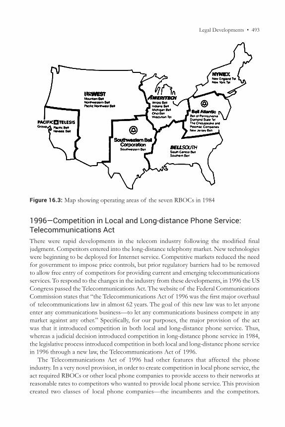
Legal Developments • 493
1996—Competition in Local and Long-distance Phone Service: Telecommunications ActThere were rapid developments in the telecom industry following the modified final judgment. Competitors entered into the long-distance telephony market. New technologies were beginning to be deployed for Internet service. Competitive markets reduced the need for government to impose price controls, but prior regulatory barriers had to be removed to allow free entry of competitors for providing current and emerging telecommunications services. To respond to the changes in the industry from these developments, in 1996 the US Congress passed the Telecommunications Act. The website of the Federal Communications Commission states that “the Telecommunications Act of 1996 was the first major overhaul of telecommunications law in almost 62 years. The goal of this new law was to let anyone enter any communications business—to let any communications business compete in any market against any other.” Specifically, for our purposes, the major provision of the act was that it introduced competition in both local and long-distance phone service. Thus, whereas a judicial decision introduced competition in long-distance phone service in 1984, the legislative process introduced competition in both local and long-distance phone service in 1996 through a new law, the Telecommunications Act of 1996.
The Telecommunications Act of 1996 had other features that affected the phone industry. In a very novel provision, in order to create competition in local phone service, the act required RBOCs or other local phone companies to provide access to their networks at reasonable rates to competitors who wanted to provide local phone service. This provision created two classes of local phone companies—the incumbents and the competitors.
Figure 16.3: Map showing operating areas of the seven RBOCs in 1984
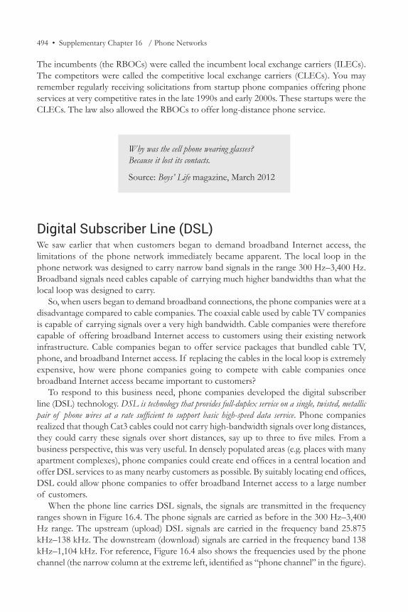
494 • Supplementary Chapter 16 / Phone Networks
The incumbents (the RBOCs) were called the incumbent local exchange carriers (ILECs). The competitors were called the competitive local exchange carriers (CLECs). You may remember regularly receiving solicitations from startup phone companies offering phone services at very competitive rates in the late 1990s and early 2000s. These startups were the CLECs. The law also allowed the RBOCs to offer long-distance phone service.
Digital Subscriber Line (DSL)We saw earlier that when customers began to demand broadband Internet access, the limitations of the phone network immediately became apparent. The local loop in the phone network was designed to carry narrow band signals in the range 300 Hz–3,400 Hz. Broadband signals need cables capable of carrying much higher bandwidths than what the local loop was designed to carry.
So, when users began to demand broadband connections, the phone companies were at a disadvantage compared to cable companies. The coaxial cable used by cable TV companies is capable of carrying signals over a very high bandwidth. Cable companies were therefore capable of offering broadband Internet access to customers using their existing network infrastructure. Cable companies began to offer service packages that bundled cable TV, phone, and broadband Internet access. If replacing the cables in the local loop is extremely expensive, how were phone companies going to compete with cable companies once broadband Internet access became important to customers?
To respond to this business need, phone companies developed the digital subscriber line (DSL) technology. DSL is technology that provides full-duplex service on a single, twisted, metallic pair of phone wires at a rate sufficient to support basic high-speed data service. Phone companies realized that though Cat3 cables could not carry high-bandwidth signals over long distances, they could carry these signals over short distances, say up to three to five miles. From a business perspective, this was very useful. In densely populated areas (e.g. places with many apartment complexes), phone companies could create end offices in a central location and offer DSL services to as many nearby customers as possible. By suitably locating end offices, DSL could allow phone companies to offer broadband Internet access to a large number of customers.
When the phone line carries DSL signals, the signals are transmitted in the frequency ranges shown in Figure 16.4. The phone signals are carried as before in the 300 Hz–3,400 Hz range. The upstream (upload) DSL signals are carried in the frequency band 25.875 kHz–138 kHz. The downstream (download) signals are carried in the frequency band 138 kHz–1,104 kHz. For reference, Figure 16.4 also shows the frequencies used by the phone channel (the narrow column at the extreme left, identified as “phone channel” in the figure).
Why was the cell phone wearing glasses?Because it lost its contacts.
Source: Boys’ Life magazine, March 2012
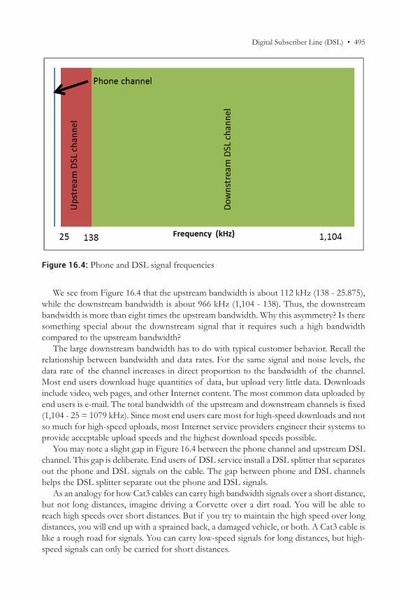
Digital Subscriber Line (DSL) • 495
We see from Figure 16.4 that the upstream bandwidth is about 112 kHz (138 - 25.875), while the downstream bandwidth is about 966 kHz (1,104 - 138). Thus, the downstream bandwidth is more than eight times the upstream bandwidth. Why this asymmetry? Is there something special about the downstream signal that it requires such a high bandwidth compared to the upstream bandwidth?
The large downstream bandwidth has to do with typical customer behavior. Recall the relationship between bandwidth and data rates. For the same signal and noise levels, the data rate of the channel increases in direct proportion to the bandwidth of the channel. Most end users download huge quantities of data, but upload very little data. Downloads include video, web pages, and other Internet content. The most common data uploaded by end users is e-mail. The total bandwidth of the upstream and downstream channels is fixed (1,104 - 25 = 1079 kHz). Since most end users care most for high-speed downloads and not so much for high-speed uploads, most Internet service providers engineer their systems to provide acceptable upload speeds and the highest download speeds possible.
You may note a slight gap in Figure 16.4 between the phone channel and upstream DSL channel. This gap is deliberate. End users of DSL service install a DSL splitter that separates out the phone and DSL signals on the cable. The gap between phone and DSL channels helps the DSL splitter separate out the phone and DSL signals.
As an analogy for how Cat3 cables can carry high bandwidth signals over a short distance, but not long distances, imagine driving a Corvette over a dirt road. You will be able to reach high speeds over short distances. But if you try to maintain the high speed over long distances, you will end up with a sprained back, a damaged vehicle, or both. A Cat3 cable is like a rough road for signals. You can carry low-speed signals for long distances, but high-speed signals can only be carried for short distances.
Figure 16.4: Phone and DSL signal frequencies
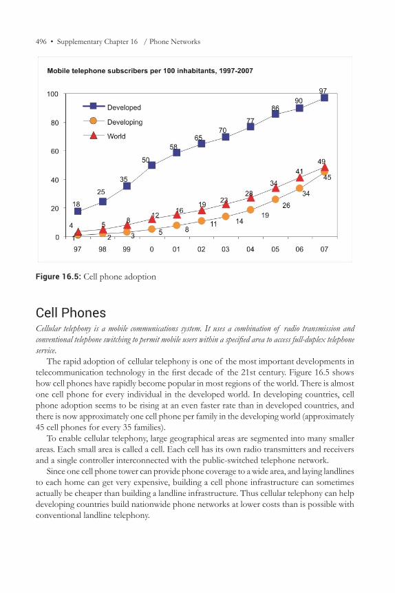
496 • Supplementary Chapter 16 / Phone Networks
Cell PhonesCellular telephony is a mobile communications system. It uses a combination of radio transmission and conventional telephone switching to permit mobile users within a specified area to access full-duplex telephone service.
The rapid adoption of cellular telephony is one of the most important developments in telecommunication technology in the first decade of the 21st century. Figure 16.5 shows how cell phones have rapidly become popular in most regions of the world. There is almost one cell phone for every individual in the developed world. In developing countries, cell phone adoption seems to be rising at an even faster rate than in developed countries, and there is now approximately one cell phone per family in the developing world (approximately 45 cell phones for every 35 families).
To enable cellular telephony, large geographical areas are segmented into many smaller areas. Each small area is called a cell. Each cell has its own radio transmitters and receivers and a single controller interconnected with the public-switched telephone network.
Since one cell phone tower can provide phone coverage to a wide area, and laying landlines to each home can get very expensive, building a cell phone infrastructure can sometimes actually be cheaper than building a landline infrastructure. Thus cellular telephony can help developing countries build nationwide phone networks at lower costs than is possible with conventional landline telephony.
Figure 16.5: Cell phone adoption
Cell Phones • 497
Cell Phone Technology EvolutionCommercial cell phone networks have been available in different parts of the world from the early 1980s. Since then, there has been steady evolutionary improvement in the technology. There have also been two clearly identifiable revolutionary improvements in cell phone technologies. Each revolutionary improvement in cell phone technology is labeled as a generation in the telecommunications industry. Figure 16.6 shows the key features of each generation of cell phones.6
The earliest cell phone networks were built starting around 1980 and are now called first-generation cell phone networks. These phones used analog signals, using frequency modulation to transmit the speaker’s voice over the allocated carrier frequency. This is a very simple technology that had been used for more than 50 years for wireless communication in applications such as car radios. Though the phones using this technology were heavy and unwieldy, did not support data transmission, and used wireless frequencies very inefficiently, the first generation set the stage for future development of the technologies and markets. First-generation cellular phone networks were popular throughout the 1980s.
In the first revolutionary change, digital signals replaced analog signals to carry voice. Networks and equipment using this technology are called second-generation cell phone networks. The primary advantage of using digital signals is that using data-compression techniques, it is possible to send multiple digital signals using the same bandwidth used by one analog signal. Thus, second-generation networks made more efficient utilization of bandwidth compared to the first-generation cell phone networks. Second-generation networks began to be deployed just after 1990. Since the second generation used digital signals, second-generation networks also added packet-data service, enabling cell phones to be used as data modems at data rates of approximately 15 Kbps.
The current cell phone networks are called third-generation cell phone networks. Specifications for the third generation of cell phone networks were defined under the leadership of the International Telecommunications Union (ITU) in 2000. The revolutionary feature of third-generation cell phone networks compared to second-generation networks is much higher data rates. Both second- and third-generation cell phone networks use digital signals and both support voice and data. Thus, the distinction between second-generation and third-generation cell phone networks is not as distinct as the distinction between the first and second generation of cell phones. However, as the ITU states, the
6 M. Agrawal, K. Chari, and R. Sankar, “Demystifying Wireless Technologies: Navigating Through the Wireless Technology Maze,” Communications of the AIS, 12 (2003): 166–182. (Excerpt used with permission from the Association for Information Systems, Atlanta, GA. All rights reserved.)
Ethan: Two antennas met on a roof, fell in love, and got married.Grace: How was the ceremony?Ethan: I don’t know, but the reception was terrific!
Source: Boys’ Life magazine, July 2014
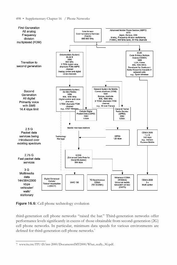
498 • Supplementary Chapter 16 / Phone Networks
third-generation cell phone networks “raised the bar.” Third-generation networks offer performance levels significantly in excess of those obtainable from second-generation (2G) cell phone networks. In particular, minimum data speeds for various environments are defined for third-generation cell phone networks.7
7 www.itu.int/ITU-D/imt-2000/DocumentsIMT2000/What_really_3G.pdf.
Figure 16.6: Cell phone technology evolution
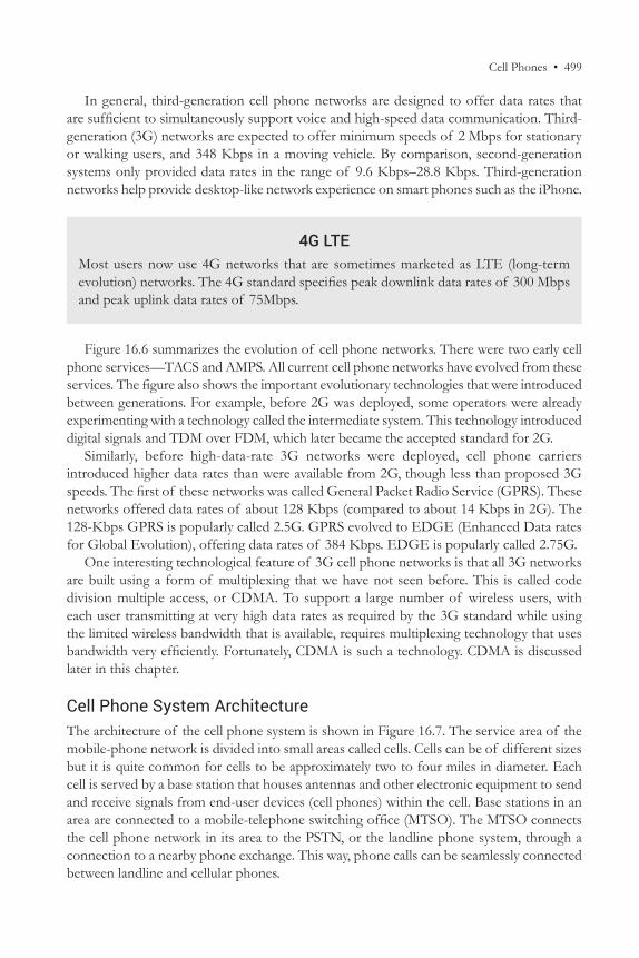
Cell Phones • 499
In general, third-generation cell phone networks are designed to offer data rates that are sufficient to simultaneously support voice and high-speed data communication. Third-generation (3G) networks are expected to offer minimum speeds of 2 Mbps for stationary or walking users, and 348 Kbps in a moving vehicle. By comparison, second-generation systems only provided data rates in the range of 9.6 Kbps–28.8 Kbps. Third-generation networks help provide desktop-like network experience on smart phones such as the iPhone.
Figure 16.6 summarizes the evolution of cell phone networks. There were two early cell phone services—TACS and AMPS. All current cell phone networks have evolved from these services. The figure also shows the important evolutionary technologies that were introduced between generations. For example, before 2G was deployed, some operators were already experimenting with a technology called the intermediate system. This technology introduced digital signals and TDM over FDM, which later became the accepted standard for 2G.
Similarly, before high-data-rate 3G networks were deployed, cell phone carriers introduced higher data rates than were available from 2G, though less than proposed 3G speeds. The first of these networks was called General Packet Radio Service (GPRS). These networks offered data rates of about 128 Kbps (compared to about 14 Kbps in 2G). The 128-Kbps GPRS is popularly called 2.5G. GPRS evolved to EDGE (Enhanced Data rates for Global Evolution), offering data rates of 384 Kbps. EDGE is popularly called 2.75G.
One interesting technological feature of 3G cell phone networks is that all 3G networks are built using a form of multiplexing that we have not seen before. This is called code division multiple access, or CDMA. To support a large number of wireless users, with each user transmitting at very high data rates as required by the 3G standard while using the limited wireless bandwidth that is available, requires multiplexing technology that uses bandwidth very efficiently. Fortunately, CDMA is such a technology. CDMA is discussed later in this chapter.
Cell Phone System ArchitectureThe architecture of the cell phone system is shown in Figure 16.7. The service area of the mobile-phone network is divided into small areas called cells. Cells can be of different sizes but it is quite common for cells to be approximately two to four miles in diameter. Each cell is served by a base station that houses antennas and other electronic equipment to send and receive signals from end-user devices (cell phones) within the cell. Base stations in an area are connected to a mobile-telephone switching office (MTSO). The MTSO connects the cell phone network in its area to the PSTN, or the landline phone system, through a connection to a nearby phone exchange. This way, phone calls can be seamlessly connected between landline and cellular phones.
4G LTEMost users now use 4G networks that are sometimes marketed as LTE (long-term evolution) networks. The 4G standard specifies peak downlink data rates of 300 Mbps and peak uplink data rates of 75Mbps.
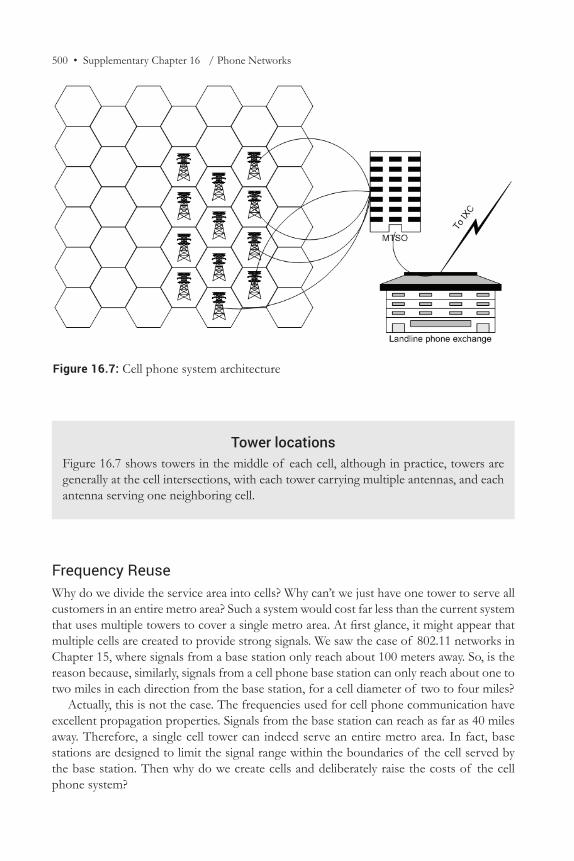
500 • Supplementary Chapter 16 / Phone Networks
Frequency ReuseWhy do we divide the service area into cells? Why can’t we just have one tower to serve all customers in an entire metro area? Such a system would cost far less than the current system that uses multiple towers to cover a single metro area. At first glance, it might appear that multiple cells are created to provide strong signals. We saw the case of 802.11 networks in Chapter 15, where signals from a base station only reach about 100 meters away. So, is the reason because, similarly, signals from a cell phone base station can only reach about one to two miles in each direction from the base station, for a cell diameter of two to four miles?
Actually, this is not the case. The frequencies used for cell phone communication have excellent propagation properties. Signals from the base station can reach as far as 40 miles away. Therefore, a single cell tower can indeed serve an entire metro area. In fact, base stations are designed to limit the signal range within the boundaries of the cell served by the base station. Then why do we create cells and deliberately raise the costs of the cell phone system?
Figure 16.7: Cell phone system architecture
Tower locationsFigure 16.7 shows towers in the middle of each cell, although in practice, towers are generally at the cell intersections, with each tower carrying multiple antennas, and each antenna serving one neighboring cell.
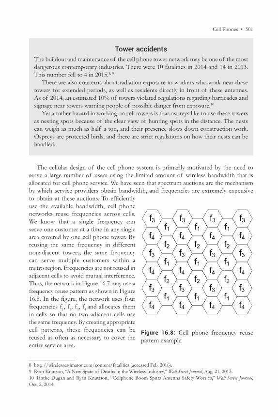
Cell Phones • 501
Tower accidentsThe buildout and maintenance of the cell phone tower network may be one of the most dangerous contemporary industries. There were 10 fatalities in 2014 and 14 in 2013. This number fell to 4 in 2015.8, 9
There are also concerns about radiation exposure to workers who work near these towers for extended periods, as well as residents directly in front of these antennas. As of 2014, an estimated 10% of towers violated regulations regarding barricades and signage near towers warning people of possible danger from exposure.10
Yet another hazard in working on cell towers is that ospreys like to use these towers as nesting spots because of the clear view of hunting spots in the distance. The nests can weigh as much as half a ton, and their presence slows down construction work. Ospreys are protected birds, and there are strict regulations on how their nests can be handled.
The cellular design of the cell phone system is primarily motivated by the need to serve a large number of users using the limited amount of wireless bandwidth that is allocated for cell phone service. We have seen that spectrum auctions are the mechanism by which service providers obtain bandwidth, and frequencies are extremely expensive to obtain at these auctions. To efficiently use the available bandwidth, cell phone networks reuse frequencies across cells. We know that a single frequency can serve one customer at a time in any single area covered by one cell phone tower. By reusing the same frequency in different nonadjacent towers, the same frequency can serve multiple customers within a metro region. Frequencies are not reused in adjacent cells to avoid mutual interference. Thus, the network in Figure 16.7 may use a frequency reuse pattern as shown in Figure 16.8. In the figure, the network uses four frequencies f1, f2, f3, f4 and allocates them in cells so that no two adjacent cells use the same frequency. By creating appropriate cell patterns, these frequencies can be reused as often as necessary to cover the entire service area.
8 http://wirelessestimator.com/content/fatalities (accessed Feb. 2016).9 Ryan Knutson, “A New Spate of Deaths in the Wireless Industry,” Wall Street Journal, Aug. 21, 2013.10 Ianthe Dugan and Ryan Knuttson, “Cellphone Boom Spurs Antenna Safety Worries,” Wall Street Journal, Oct. 2, 2014.
Figure 16.8: Cell phone frequency reuse pattern example
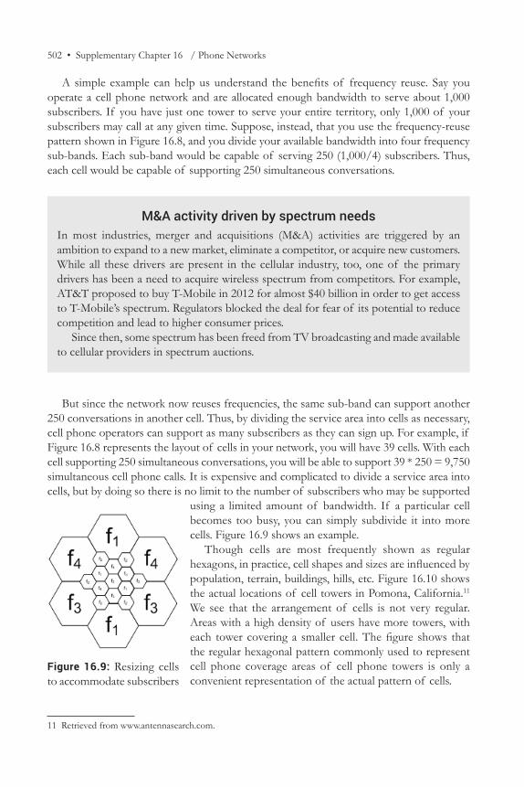
502 • Supplementary Chapter 16 / Phone Networks
A simple example can help us understand the benefits of frequency reuse. Say you operate a cell phone network and are allocated enough bandwidth to serve about 1,000 subscribers. If you have just one tower to serve your entire territory, only 1,000 of your subscribers may call at any given time. Suppose, instead, that you use the frequency-reuse pattern shown in Figure 16.8, and you divide your available bandwidth into four frequency sub-bands. Each sub-band would be capable of serving 250 (1,000/4) subscribers. Thus, each cell would be capable of supporting 250 simultaneous conversations.
But since the network now reuses frequencies, the same sub-band can support another 250 conversations in another cell. Thus, by dividing the service area into cells as necessary, cell phone operators can support as many subscribers as they can sign up. For example, if Figure 16.8 represents the layout of cells in your network, you will have 39 cells. With each cell supporting 250 simultaneous conversations, you will be able to support 39 * 250 = 9,750 simultaneous cell phone calls. It is expensive and complicated to divide a service area into cells, but by doing so there is no limit to the number of subscribers who may be supported
using a limited amount of bandwidth. If a particular cell becomes too busy, you can simply subdivide it into more cells. Figure 16.9 shows an example.
Though cells are most frequently shown as regular hexagons, in practice, cell shapes and sizes are influenced by population, terrain, buildings, hills, etc. Figure 16.10 shows the actual locations of cell towers in Pomona, California.11 We see that the arrangement of cells is not very regular. Areas with a high density of users have more towers, with each tower covering a smaller cell. The figure shows that the regular hexagonal pattern commonly used to represent cell phone coverage areas of cell phone towers is only a convenient representation of the actual pattern of cells.
11 Retrieved from www.antennasearch.com.
Figure 16.9: Resizing cells to accommodate subscribers
M&A activity driven by spectrum needsIn most industries, merger and acquisitions (M&A) activities are triggered by an ambition to expand to a new market, eliminate a competitor, or acquire new customers. While all these drivers are present in the cellular industry, too, one of the primary drivers has been a need to acquire wireless spectrum from competitors. For example, AT&T proposed to buy T-Mobile in 2012 for almost $40 billion in order to get access to T-Mobile’s spectrum. Regulators blocked the deal for fear of its potential to reduce competition and lead to higher consumer prices.
Since then, some spectrum has been freed from TV broadcasting and made available to cellular providers in spectrum auctions.
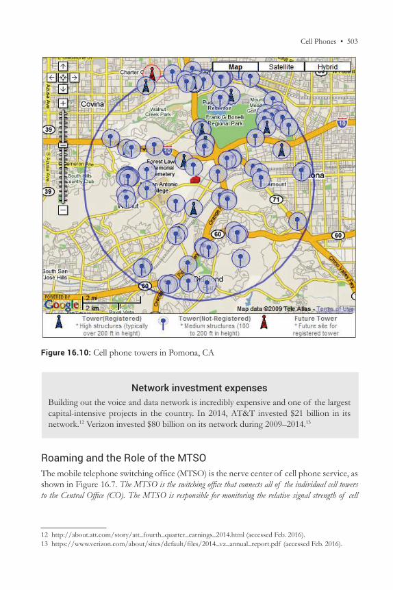
Cell Phones • 503
Network investment expensesBuilding out the voice and data network is incredibly expensive and one of the largest capital-intensive projects in the country. In 2014, AT&T invested $21 billion in its network.12 Verizon invested $80 billion on its network during 2009–2014.13
Roaming and the Role of the MTSOThe mobile telephone switching office (MTSO) is the nerve center of cell phone service, as shown in Figure 16.7. The MTSO is the switching office that connects all of the individual cell towers to the Central Office (CO). The MTSO is responsible for monitoring the relative signal strength of cell
12 http://about.att.com/story/att_fourth_quarter_earnings_2014.html (accessed Feb. 2016).13 https://www.verizon.com/about/sites/default/files/2014_vz_annual_report.pdf (accessed Feb. 2016).
Figure 16.10: Cell phone towers in Pomona, CA
504 • Supplementary Chapter 16 / Phone Networks
phones as reported by each of the cell towers, and switching conversations to the cell towers with the best possible reception.
Every cell phone has a home MTSO. When a cell phone is switched on, it periodically broadcasts its presence. These broadcasts are received by all the towers in its coverage area, and all the towers send the signal strength and other information about the phone to the MTSO. The MTSO identifies the tower receiving the best signal from the phone and instructs the tower to handle calls from the phone. The selected MTSO also informs the home MTSO of the mobile phone user that the phone is located within its service area. For example, the home MTSO for a cell phone number with area code 407 will be in Orlando, Florida. If the cell phone is currently located in Kingston, Rhode Island, the local MTSO in Kingston, Rhode Island, will inform the home MTSO of the cell phone in Orlando that the cell phone is located in Kingston. When someone dials the 407 number, the call is first connected to the user’s home MTSO in Orlando. The home MTSO will then direct the call to the MTSO in Kingston, Rhode Island, where the user is located. This MTSO will forward the call to the tower that is responsible for the phone.14
If the user moves away from a cell, its signals to its current cell tower weaken. Simultaneously, the signals get stronger at a tower in a neighboring cell. The MTSO uses these differences in signal strengths to transfer responsibility of handling the call to the appropriate neighboring tower. This process is called handoff. Handoff is the process of transferring a phone call in progress from one cell transmitter and frequency pair to another cell transmitter and receiver, using a different frequency pair without interruption of the call.
Code Division Multiple Access (CDMA)Third-generation cell phones use a kind of multiplexing method that we have not seen before. It is called CDMA, which stands for code division multiple access. CDMA is a coding scheme, used as a modulation technique, in which multiple channels are independently coded for transmission over a single wideband channel. Several transmissions can occur simultaneously within the same bandwidth, with the mutual interference reduced by the use of unique codes in each transmission.
We saw frequency-division multiplexing (FDM), where different signals are sent at different frequencies. By tuning into one frequency, the receiver can obtain the signal at the frequency, eliminating the signals being transmitted at all other frequencies. Another common multiplexing technique is time division multiplexing (TDM). In this scheme, each station is allowed to transmit in an allocated time slot. The receiver only listens to transmissions at the specified time slots and ignores transmissions made at other times. SONET is an example of TDM.
Whereas multiplexing schemes such as FDM and TDM are useful, they have a major limitation. Each channel is only allowed to use a fraction of the transmitting capacity of the medium. Thus, if an FDM scheme has 10 frequency slots, it can serve at most 10 users. The 11th user will have to wait till one of the earlier users hangs up.
CDMA eliminates this limitation. CDMA allows an almost unlimited number of users to transmit signals at any time using the entire bandwidth of the medium. Each communication
14 For a good early read on optimizations being attempted in the industry, see Scott Woolley, “The $10 Phone Bill,” Forbes, Nov. 2009.
Example Case—Cell Phones and Global Development • 505
is allocated a unique chipping code. Before transmission, signals are processed using the assigned chipping code. Analogous to the FDM example, the receiver processes the incoming signal using the same chipping code used by the sender. This extracts the communication of interest and eliminates most of the information in all other signals. Any number of chipping codes may be generated, and therefore any number of users may be added to a cell. The only limitation is that, as used in the cell phone system, CDMA does not eliminate all information from other signals. As a result, the background noise level in CDMA increases when the number of users increases. Eventually this can make the sound quality in the cell unacceptable. When this happens, the operator divides a large cell into smaller cells and adds new towers to serve the new cells. This is why, as shown in Figure 16.9, densely populated areas have many towers in close proximity. The hands-on exercise uses a spreadsheet example to demonstrate how four users can use CDMA to send and receive 5 bits each.
EXAMPLE CASE—Cell Phones and Global DevelopmentMo Ibrahim founded MSI Cellular Investments (later Celtel) in Africa in 1998, when the continent with a population of 950 million people had about 2 million phones. Recognizing the opportunity for a business that connected people, Mo went about building his network and company, investing more than $750 million in seven years. In 2005, when the company was bought by MTC Kuwait for $3.4 billion, it had 24 million mobile subscribers in 15 different African countries. This made it one of Africa’s most successful businesses at the time. Today, Africa has more than 350 million unique mobile subscribers. Mo has now invested in a global satellite provider, O3B, which aims to bring cell phone service to remote locations in developing countries. Mo believes Africa can offer well-run businesses growth rates of more than 30% each year, a rate unattainable anywhere else in the world.
In spite of this growth, data usage continues to be expensive and unaffordable for most users in Africa. Cell phones in Africa are primarily pre-paid, and pre-paid data costs about $11/GB. Where daily incomes for large sections of the population are below $1.25/day, $11/GB is a very heavy price to pay for Internet access.
This has created other business opportunities and the mobility-driven eco-system continues to evolve. Entrepreneurs are outfitting mini-buses with free Wi-Fi access to the Internet. These mini-buses are a popular mode of transportation in Africa, and buses that offer this service have an advantage compared to their competitors on the same routes—gathering more fare-paying passengers who use the time to browse the web and update their social media status. Each bus pays about $25/month for data, but at every stop, passengers choose Wi-Fi outfitted buses over the competition.
In another well-known underdeveloped part of the world, Afghanistan, there were only 10,000 fixed-line phones in 2001. Services such as television were non-existent at the time. Today, about 20 million of the 30 million people in the country use mobile phones, about the same number of people who regularly watch television. Similarly, the road network has grown from 32 paved miles to more than 7,500 paved miles. This connectivity will hopefully bring political accountability and improve lives.
506 • Supplementary Chapter 16 / Phone Networks
In China, where development is more rapid and advanced, mobile telephony is bringing other changes. In 2005, most consumer transactions in the country were conducted by cash. In 2015, on the other hand, more than 350 million people used their cell phones for payment, a growth of more than 60% compared to 2014. The volume of payments made through mobile phones was estimated at $2.5 trillion in 2015. Alibaba and WeChat are the leading players in the industry in China. Alibaba charges a maximum service fee of 0.6% for each transaction. By comparison, credit card swipe fees in the US can exceed 1.5% and are the second- or third-highest cost for retailers, after wages and healthcare benefits. Alibaba and WeChat have established protections similar to those offered by US credit card companies to establish reputations for trust among both buyers and sellers. Alibaba even offers investment instruments such as money market funds that offer higher interest rates than state-owned banks, so customers use these applications also as their wealth-management solutions.
References 1. Mohseni, Saad. “The Untold Story of Afghan Progress.” Wall Street Journal, Mar. 17,
2013. 2. Salvaterra, Neanda. “Mobile Pioneer Sees Rich Promise in Africa.” Wall Street Journal,
Apr. 18, 2011. 3. Vogt, Heidi. “No Wi-Fi at home? Then Take a Bus.” Wall Street Journal, Apr. 15, 2014. 4. Yuan, Li. “How Mobile Payments Reshape Lifestyles.” Wall Street Journal, Feb. 24, 2016.
SummaryThis chapter provided a high-level overview of landline and cell phone networks. Though many functions of the phone system are moving over to computerized communication technologies, such as e-mail, IM, and VoIP, the phone continues to be an important medium for business and personal communication. The phone system transmits signals in the frequency range 300 Hz–3,400 Hz. Each end user is connected to the nearest end office of the phone company using a dedicated pair of copper wires called the local loop. The phone system is used in many parts of the world to offer high-speed Internet service using a technology called Digital Subscriber Line (DSL).
The phone system in the United States was initially operated by one company, AT&T. In 1984, the company agreed in a court settlement to focus exclusively on providing long-distance phone service. AT&T’s local phone service networks were divested as seven local phone companies. Later, in 1996, Congress passed the Telecommunications Act, which opened up all sectors of telephony to competition. The Telecommunications Act also required incumbent local phone companies with established phone networks to allow competitors to use the incumbent phone company’s networks at reasonable prices to compete with the incumbent.
Of late, cellular telephony is becoming increasingly popular, even in developing countries. In many cases, developing countries actually find it cheaper to set up a cell phone network than to set up a landline phone network. Cell phone networks divide the coverage area into
Review Questions • 507
small cells. Users in each cell are served by a cell phone tower located in the cell. As users move from cell to cell, their calls are handed off to the most appropriate cell phone tower in the area. The division of the coverage area into cells permits frequency reuse, which allows a small set of frequencies to be used to serve as many subscribers as necessary.
Cell phone technologies have evolved in three distinct phases. Each phase is called a generation. We are currently using the third generation of cell phone technologies, creatively called 3G. The third generation uses a multiplexing technology called CDMA, which is very efficient in using bandwidth. CDMA enables cell phone networks to offer high-data-rate network connections to a large number of end users using the very limited bandwidth available for 3G networks.
In which of the following contexts were the words, “Watson, come in here please” used in homage to Alexander Graham Bell:15
A. March 21, 2006, Biz Stone’s response, on seeing the first tweet by Jack DorseyB. April 8, 2008, Noah Glass to Evan Williams, on hearing about the Twitter IPOC. November 6, 2008, Evan Williams to Noah Glass, on being offered a position at TwitterD. January 23, 2009, Noah Glass to Biz Stone, on being fired from Twitter
About the ColophonFirst impressions are lasting impressions. It is therefore not surprising that the first phrase spoken on the telephone by the inventor of the technology is also one of the most memorable phrases ever communicated using the technology.
Alexander Graham Bell maintained meticulous diaries of his experiments to create the telephone. In his diary entry of March 10, 187616 (Figure 16.11), Alexander Graham Bell described his first successful communication using the telephone. When he spoke through the instrument, his assistant, Thomas A. Watson, was in the next room. In the diary, Graham Bell wrote, “I then shouted into M the following sentence: ‘Mr. Watson—come here—I want to see you.’ To my delight he came and declared that he had heard and understood what I said.”
REVIEW QUESTIONS 1. What are some of the ways in which the phone network has been important for data
communications over the years? 2. What are some of the important landmarks in the development of phone service? 3. What is circuit switching? 4. How has the adoption of landline telephony evolved in the last decade?
15 Answer: A. Source: Nick Bilton, Hatching Twitter (Penguin, 2013). All people mentioned are co-founders of Twitter.16 www.loc.gov/exhibits/treasures/trr002.html.
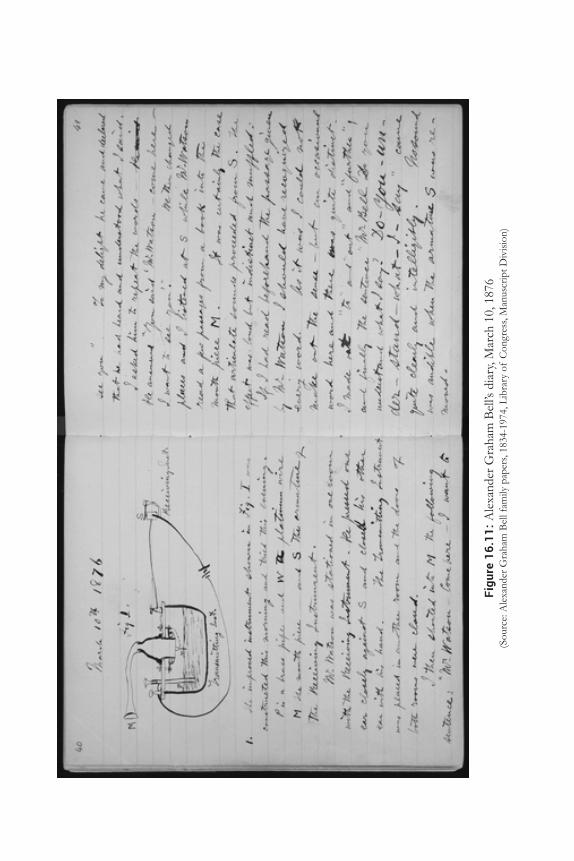
Figu
re 1
6.11
: Ale
xand
er G
raha
m B
ell’s
dia
ry, M
arch
10,
187
6(S
ourc
e: A
lexa
nder
Gra
ham
Bel
l fam
ily p
aper
s, 18
34-1
974,
Lib
rary
of
Con
gres
s, M
anus
crip
t Div
ision
)
Example Case Questions • 509
5. What is the local loop in the context of phone service? 6. What is the central office or the end office? 7. What are inter-exchange carriers (IXC)? What are some similarities and differences between
the local loop and IXC links? 8. What is hertz? 9. Why is the phone system designed to carry signals in the frequency range 33 Hz–3,400
Hz?10. What is digital subscriber line (DSL)?11. What was the motivation for the development of DSL technology?12. What are the three kinds of signals on a cable providing DSL and phone service? What
are the frequency ranges used by the three signals?13. Why do most ISPs provide much higher downstream data rates than upstream data
rates?14. Why is the modified final judgment important to the development of phone service in
the United States?15. What was the outcome of the modified final judgment?16. What were the circumstances that led to the Telecommunications Act of 1996?17. What were some of the implications of the Telecommunications Act of 1996?18. What is cellular telephony?19. What are the three generations of cellular telephony service? Describe the important
features of each generation of cell phone service.20. What is frequency reuse in the context of cellular telephony? Why is frequency reuse
necessary for cellular telephony?21. Why are service areas divided into small cells for cellular telephony?22. What is the MTSO in cell phone service? What are the important roles of the MTSO?23. What is handoff? Why is handoff important? How does it work?24. What is CDMA?25. How is CDMA better suited than TDM or FDM for cellular telephony?
EXAMPLE CASE QUESTIONS 1. What are some of the most promising investment opportunities in Africa and the
developing world today? 2. If you were appointed the regional manager for a cell phone company in Africa, with
responsibility to increase sales, what are some specific steps you would take? Briefly justify your recommendations.
3. Have you used mobile payments? Briefly describe your experience with mobile payments.
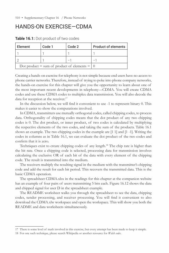
510 • Supplementary Chapter 16 / Phone Networks
HANDS-ON EXERCISE—CDMA
Table 16.1: Dot product of two codes
Element Code 1 Code 2 Product of elements
1 1 1 1
2 1 −1 −1Dot product = sum of product of elements = 0
Creating a hands-on exercise for telephony is not simple because end users have no access to phone carrier networks. Therefore, instead of trying to poke into phone company networks, the hands-on exercise for this chapter will give you the opportunity to learn about one of the most important recent developments in telephony—CDMA. You will create CDMA codes and use these CDMA codes to multiplex data transmission. You will also decode the data for reception at the receiver.17
In the discussion below, we will find it convenient to use -1 to represent binary 0. This makes it easier to show the computations involved.
In CDMA, transmitters use mutually orthogonal codes, called chipping codes, to process data. Orthogonality of chipping codes means that the dot product of any two chipping codes is 0. The dot product, or inner product, of two codes is calculated by multiplying the respective elements of the two codes, and taking the sum of the products. Table 16.1 shows an example. The two chipping codes in the example are [1 1] and [1 -1]. Writing the codes in columns as in Table 16.1, we can evaluate the dot product of the two codes and confirm that it is zero.
Techniques exist to create chipping codes of any length.18 The chip rate is higher than the bit rate. Once a chipping code is selected, processing data for transmission involves calculating the exclusive OR of each bit of the data with every element of the chipping code. The result is transmitted into the medium.
The receivers multiply the resulting signal in the medium with the transmitter’s chipping code and add the result for each bit period. This recovers the transmitted data. This is the basic CDMA operation.
The spreadsheet CDMA.xlsx in the readings for this chapter at the companion website has an example of four pairs of users transmitting 5 bits each. Figure 16.12 shows the data and chipped signal for user D in the spreadsheet example.
The README worksheet walks you through the spreadsheet to see the data, chipping codes, sender processing, and receiver processing. You will find it convenient to also download the CDMA.xlw workspace and open the workspace. This will show you both the README and data worksheets simultaneously.
17 There is some level of math involved in this exercise, but every attempt has been made to keep it simple.18 For one such technique, please search Wikipedia or another resource for Walsh codes.
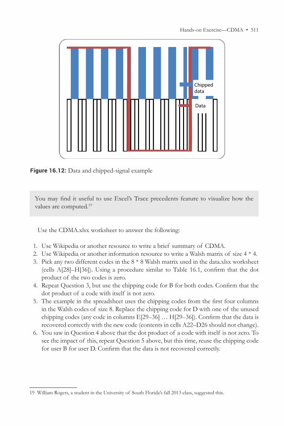
Hands-on Exercise—CDMA • 511
You may find it useful to use Excel’s Trace precedents feature to visualize how the values are computed.19
Use the CDMA.xlsx worksheet to answer the following:
1. Use Wikipedia or another resource to write a brief summary of CDMA. 2. Use Wikipedia or another information resource to write a Walsh matrix of size 4 * 4. 3. Pick any two different codes in the 8 * 8 Walsh matrix used in the data.xlsx worksheet
(cells A[28]–H[36]). Using a procedure similar to Table 16.1, confirm that the dot product of the two codes is zero.
4. Repeat Question 3, but use the chipping code for B for both codes. Confirm that the dot product of a code with itself is not zero.
5. The example in the spreadsheet uses the chipping codes from the first four columns in the Walsh codes of size 8. Replace the chipping code for D with one of the unused chipping codes (any code in columns E[29–36] … H[29–36]). Confirm that the data is recovered correctly with the new code (contents in cells A22–D26 should not change).
6. You saw in Question 4 above that the dot product of a code with itself is not zero. To see the impact of this, repeat Question 5 above, but this time, reuse the chipping code for user B for user D. Confirm that the data is not recovered correctly.
19 William Rogers, a student in the University of South Florida’s fall 2013 class, suggested this.
Figure 16.12: Data and chipped-signal example
Chippeddata
Data

512 • Supplementary Chapter 16 / Phone Networks
CRITICAL-THINKING EXERCISE—Other Three BillionairesThe company we saw in the example case, O3B, selected its name to represent the “other 3 billion” people who did not have Internet access. However, given the range of its customers, the company is sometimes mocked as representing the “other 3 billionaires” for bringing high-speed network connectivity to billionaires’ yachts, or the “other 3 battle-groups” for bringing high-speed network connectivity to military ships.
1. Should O3B protect the purity of its business by discontinuing service to profitable but wealthy customers? Justify your response.
Critical-Thinking References 1. http://spacenews.com/2014-top-fixed-satellite-service-operators-once-mocked-03b-
investment-now-force-multiplier-for-ses/.
IT INFRASTRUCTURE DESIGN EXERCISE—Switch to VoIPWhile the Mumbai location uses VoIP for all its voice traffic, the Singapore location is trying to decide whether to switch its users from traditional phones to VoIP phones. Answer the following questions:
1. Using the Internet or another information resource, compare the advantages and disadvantages of VoIP compared to traditional phone service (PSTN) along dimensions such as cost, performance, and reliability.
2. Based on the above, would you recommend that TrendyWidgets switch from PSTN to VoIP?
_____________________________________________________________________
Chapters 15 and 16 are online supplements to Business Data Communications and IT Infrastructures, 2nd Edition, by Manish Agrawal & Rekha Sharma. © 2017, Prospect Press