Embed Size (px)
Citation preview
The Unofficial Revit 2012 Certification
Exam Guide
Elise Moss
SUPPLEMENTAL
FILES ON CD
SDC
www.SDCpublications.com
Schroff Development Corporation
PUBLICATIONS
The Basics of Building a Model
2-1
Lesson Two
The Basics of Building a Model This lesson addresses the following Associate and Professional level exam questions:
Wall Properties Compound Walls Stacked Walls Doors and Windows In-Place Mass
In the Professional exam, most of the wall problems follow these steps:
Place a wall of a specific element type. (Be able to select wall type.) Place a wall by setting the location line. (Understand how to use the location line
setting.) Place a wall using different Option Settings. (Understand how to use the Options
Settings when placing a wall.) After placing the wall, place a dimension to determine if the wall was placed
correctly. After placing the wall, inspect the element properties to determine if the wall was
placed correctly.
In the Associate exam, the user will need to be familiar with the different parameters in walls and compound walls. The user should also know which options are applied to walls and when those options are available.
The Unofficial Revit 2012 Certification Exam Guide
2-2
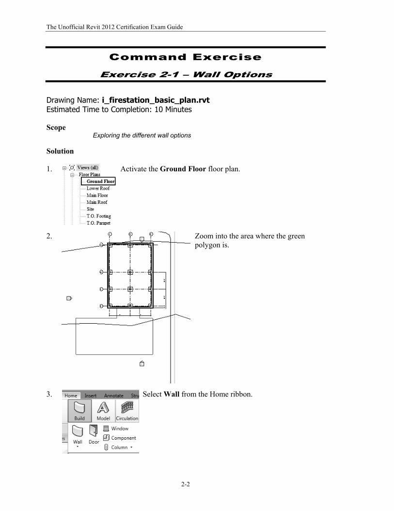
Command Exercise
Exercise 2-1 – Wall Options
Drawing Name: i_firestation_basic_plan.rvt Estimated Time to Completion: 10 Minutes Scope
Exploring the different wall options
Solution 1.
Activate the Ground Floor floor plan.
2.
Zoom into the area where the green polygon is.
3. Select Wall from the Home ribbon.
The Basics of Building a Model
2-3
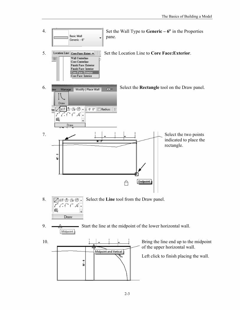
4.
Set the Wall Type to Generic – 6 in the Properties pane.
5.
Set the Location Line to Core Face:Exterior.
6.
Select the Rectangle tool on the Draw panel.
7.
Select the two points indicated to place the rectangle.
8.
Select the Line tool from the Draw panel.
9.
Start the line at the midpoint of the lower horizontal wall.
10. Bring the line end up to the midpoint of the upper horizontal wall.
Left click to finish placing the wall.
The Unofficial Revit 2012 Certification Exam Guide
2-4
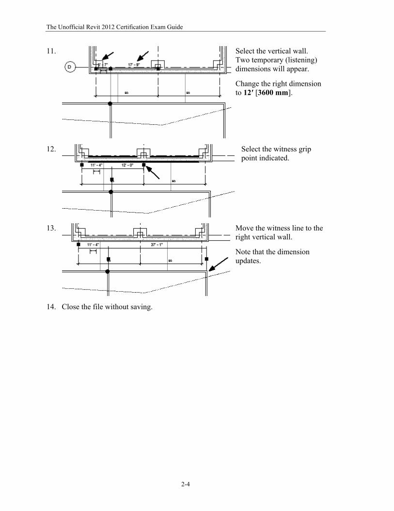
11.
Select the vertical wall. Two temporary (listening) dimensions will appear.
Change the right dimension to 12′ [3600 mm].
12.
Select the witness grip point indicated.
13.
Move the witness line to the right vertical wall.
Note that the dimension updates.
14. Close the file without saving.
The Basics of Building a Model
2-5
Command Exercise
Exercise 2-2 – Placing a Wall Sweep
Drawing Name: i_walls.rvt Estimated Time to Completion: 20 Minutes Scope
Placing a wall sweep.
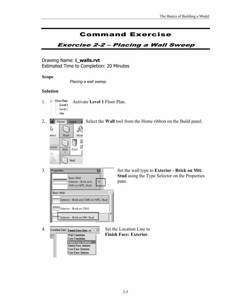
Solution 1.
Activate Level 1 Floor Plan.
2.
Select the Wall tool from the Home ribbon on the Build panel.
3.
Set the wall type to Exterior - Brick on Mtl. Stud using the Type Selector on the Properties pane.
4.
Set the Location Line to Finish Face: Exterior.
The Unofficial Revit 2012 Certification Exam Guide
2-6
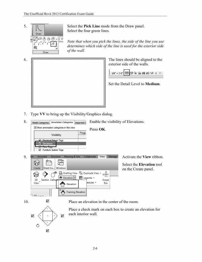
5.
Select the Pick Line mode from the Draw panel. Select the four green lines.
Note that when you pick the lines, the side of the line you use determines which side of the line is used for the exterior side of the wall.
6.
The lines should be aligned to the exterior side of the walls.
Set the Detail Level to Medium.
7. Type VV to bring up the Visibility/Graphics dialog.
8.
Enable the visibility of Elevations.
Press OK.
9.
Activate the View ribbon.
Select the Elevation tool on the Create panel.
10.
Place an elevation in the center of the room.
Place a check mark on each box to create an elevation for each interior wall.
The Basics of Building a Model
2-7
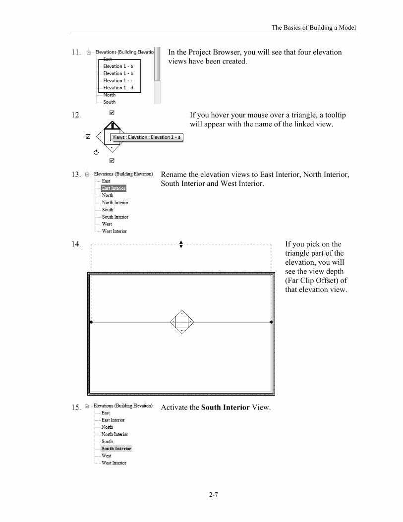
11.
In the Project Browser, you will see that four elevation views have been created.
12.
If you hover your mouse over a triangle, a tooltip will appear with the name of the linked view.
13.
Rename the elevation views to East Interior, North Interior, South Interior and West Interior.
14.
If you pick on the triangle part of the elevation, you will see the view depth (Far Clip Offset) of that elevation view.
15.
Activate the South Interior View.
The Unofficial Revit 2012 Certification Exam Guide
2-8
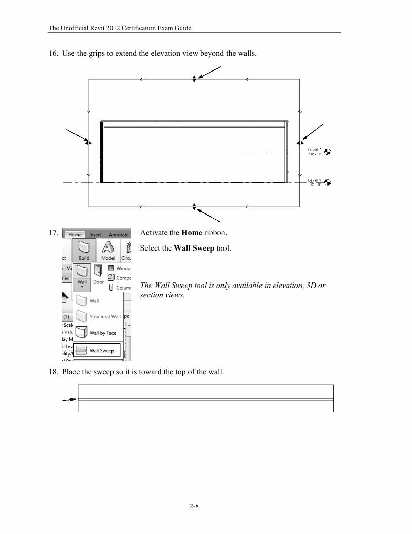
16. Use the grips to extend the elevation view beyond the walls.
17.
Activate the Home ribbon.
Select the Wall Sweep tool. The Wall Sweep tool is only available in elevation, 3D or section views.
18. Place the sweep so it is toward the top of the wall.
The Basics of Building a Model
2-9
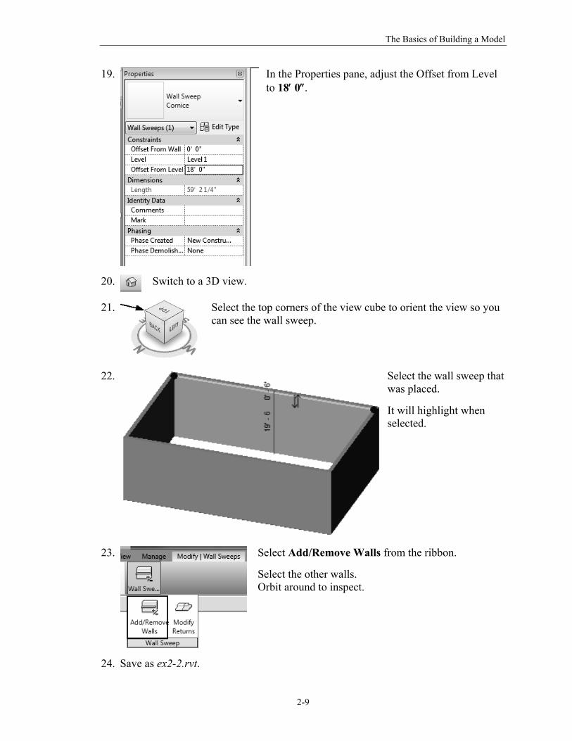
19.
In the Properties pane, adjust the Offset from Level to 18 0.
20.
Switch to a 3D view.
21.
Select the top corners of the view cube to orient the view so you can see the wall sweep.
22.
Select the wall sweep that was placed.
It will highlight when selected.
23.
Select Add/Remove Walls from the ribbon.
Select the other walls. Orbit around to inspect.
24. Save as ex2-2.rvt.
The Unofficial Revit 2012 Certification Exam Guide
2-10
Command Exercise
Exercise 2-3 – Create a Wall Sweep Style
Drawing Name: ex2-2.rvt Estimated Time to Completion: 15 Minutes Scope
Creating a wall sweep style. Loading a Profile.
Solution: 1.
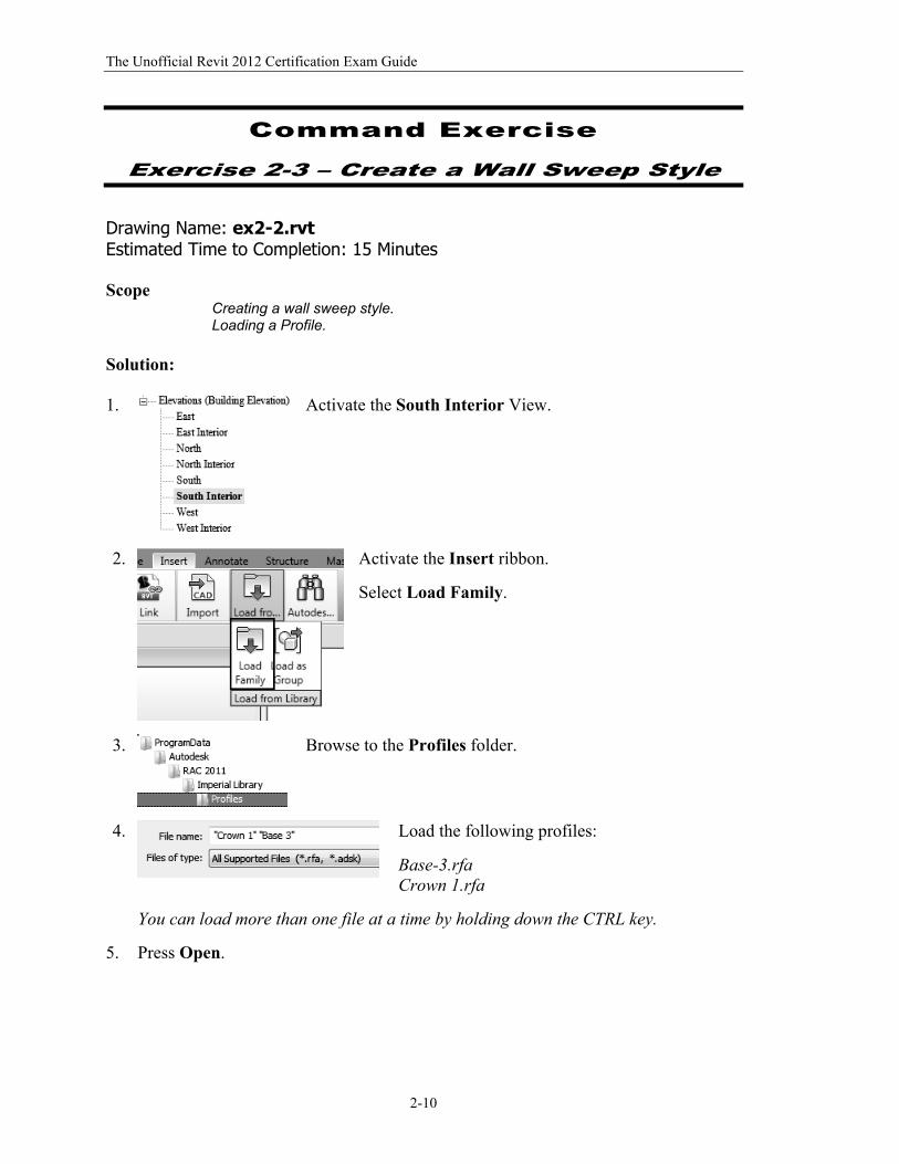
Activate the South Interior View.
2.
Activate the Insert ribbon.
Select Load Family.
3.
Browse to the Profiles folder.
4.
Load the following profiles:
Base-3.rfa Crown 1.rfa
You can load more than one file at a time by holding down the CTRL key.
5. Press Open.
The Basics of Building a Model
2-11
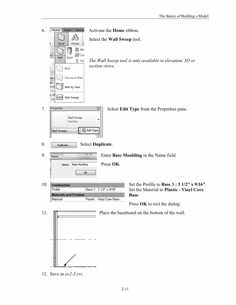
6.
Activate the Home ribbon.
Select the Wall Sweep tool. The Wall Sweep tool is only available in elevation, 3D or section views.
7.
Select Edit Type from the Properties pane.
8.
Select Duplicate.
9.
Enter Base Moulding in the Name field.
Press OK.
10.
Set the Profile to Base 3 : 3 1/2″ x 9/16″. Set the Material to Plastic - Vinyl Cove Base.
Press OK to exit the dialog.
11.
Place the baseboard on the bottom of the wall.
12. Save as ex2-3.rvt.
The Unofficial Revit 2012 Certification Exam Guide
2-12
Command Exercise
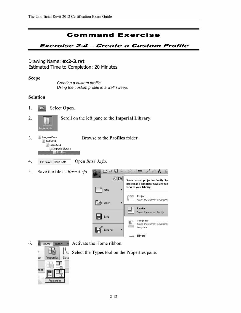
Exercise 2-4 – Create a Custom Profile
Drawing Name: ex2-3.rvt Estimated Time to Completion: 20 Minutes Scope
Creating a custom profile. Using the custom profile in a wall sweep.
Solution 1.
Select Open.
2.
Scroll on the left pane to the Imperial Library.
3.
Browse to the Profiles folder.
4.
Open Base 3.rfa.
5. Save the file as Base 4.rfa.
6.
Activate the Home ribbon.
Select the Types tool on the Properties pane.
The Basics of Building a Model
2-13
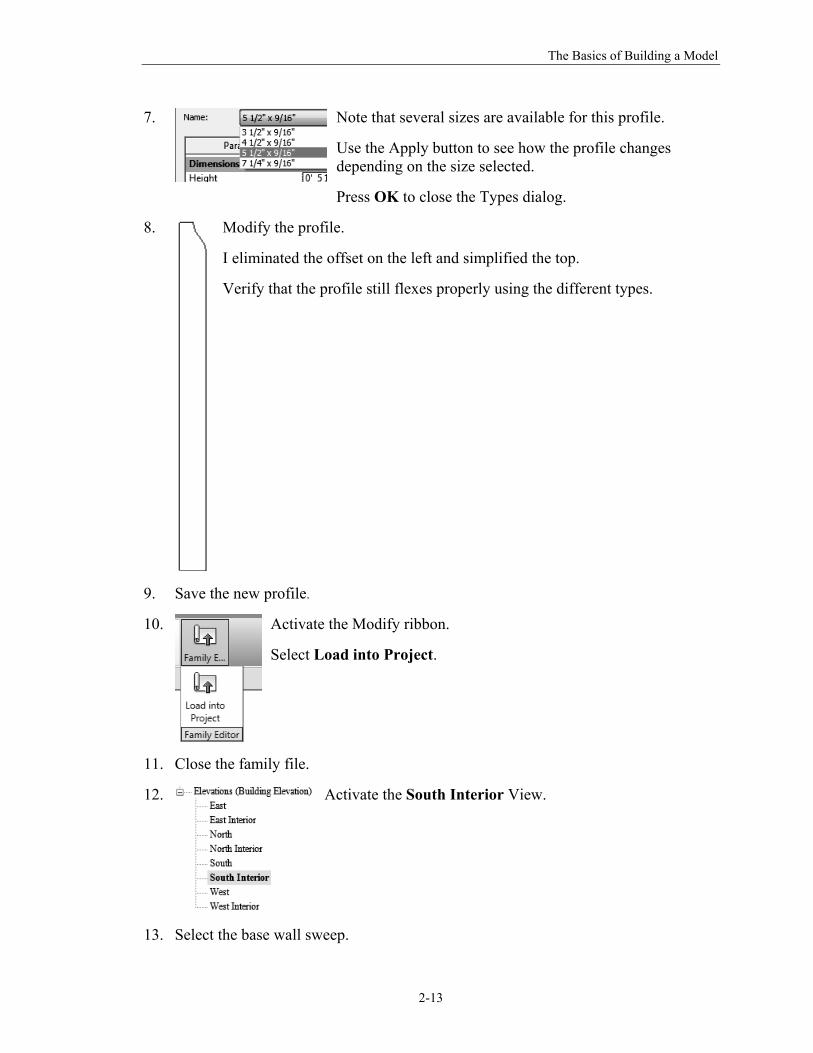
7.
Note that several sizes are available for this profile.
Use the Apply button to see how the profile changes depending on the size selected.
Press OK to close the Types dialog.
8.
Modify the profile.
I eliminated the offset on the left and simplified the top.
Verify that the profile still flexes properly using the different types.
9. Save the new profile.
10.
Activate the Modify ribbon.
Select Load into Project.
11. Close the family file.
12.
Activate the South Interior View.
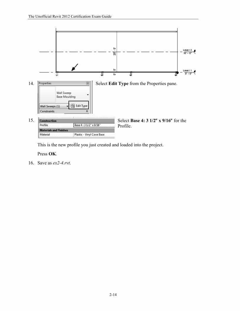
13. Select the base wall sweep.
The Unofficial Revit 2012 Certification Exam Guide
2-14
14.
Select Edit Type from the Properties pane.
15.
Select Base 4: 3 1/2 x 9/16 for the Profile.
This is the new profile you just created and loaded into the project.
Press OK.
16. Save as ex2-4.rvt.
The Basics of Building a Model
2-15
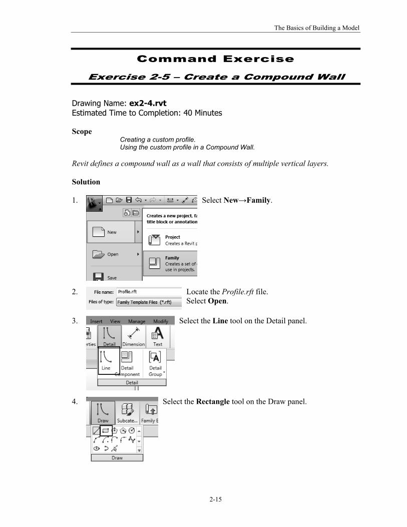
Command Exercise
Exercise 2-5 – Create a Compound Wall
Drawing Name: ex2-4.rvt Estimated Time to Completion: 40 Minutes Scope
Creating a custom profile. Using the custom profile in a Compound Wall.
Revit defines a compound wall as a wall that consists of multiple vertical layers. Solution 1.
Select New→Family.
2.
Locate the Profile.rft file. Select Open.
3.
Select the Line tool on the Detail panel.
4.
Select the Rectangle tool on the Draw panel.
The Unofficial Revit 2012 Certification Exam Guide
2-16
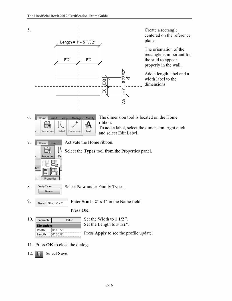
5.
Create a rectangle centered on the reference planes.
The orientation of the rectangle is important for the stud to appear properly in the wall.
Add a length label and a width label to the dimensions.
6.
The dimension tool is located on the Home ribbon. To add a label, select the dimension, right click and select Edit Label.
7.
Activate the Home ribbon.
Select the Types tool from the Properties panel.
8.
Select New under Family Types.
9.
Enter Stud - 2 x 4 in the Name field.
Press OK.
10.
Set the Width to 1 1/2". Set the Length to 3 1/2".
Press Apply to see the profile update.
11. Press OK to close the dialog.
12.
Select Save.
The Basics of Building a Model
2-17
13.
Save the file as Profile - Stud.
14.
Load the file into the ex2-4.rvt project.
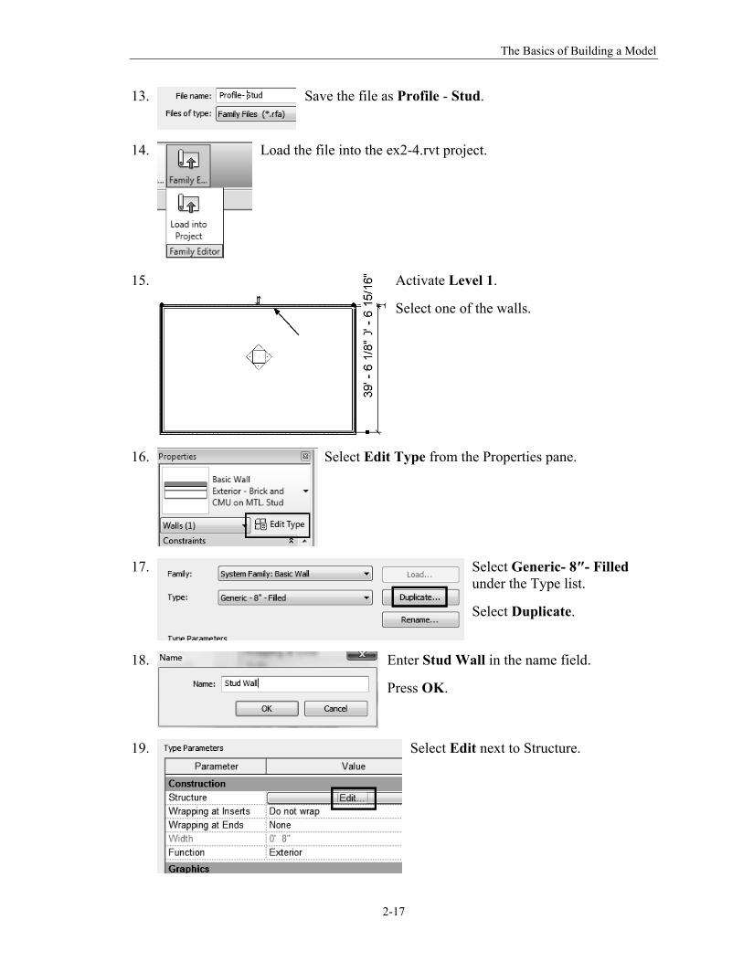
15.
Activate Level 1.
Select one of the walls.
16.
Select Edit Type from the Properties pane.
17.
Select Generic- 8″- Filled under the Type list.
Select Duplicate.
18.
Enter Stud Wall in the name field.
Press OK.
19. Select Edit next to Structure.
The Unofficial Revit 2012 Certification Exam Guide
2-18
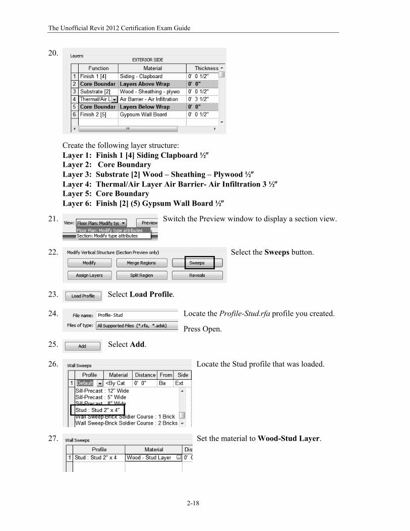
20.
Create the following layer structure: Layer 1: Finish 1 [4] Siding Clapboard ½ Layer 2: Core Boundary Layer 3: Substrate [2] Wood – Sheathing – Plywood ½ Layer 4: Thermal/Air Layer Air Barrier- Air Infiltration 3 ½ Layer 5: Core Boundary Layer 6: Finish [2] (5) Gypsum Wall Board ½
21.
Switch the Preview window to display a section view.
22.
Select the Sweeps button.
23.
Select Load Profile.
24.
Locate the Profile-Stud.rfa profile you created.
Press Open.
25.
Select Add.
26.
Locate the Stud profile that was loaded.
27.
Set the material to Wood-Stud Layer.
The Basics of Building a Model
2-19
28.
We want to locate the stud profile so it is between the gypsum board and the plywood sheath.
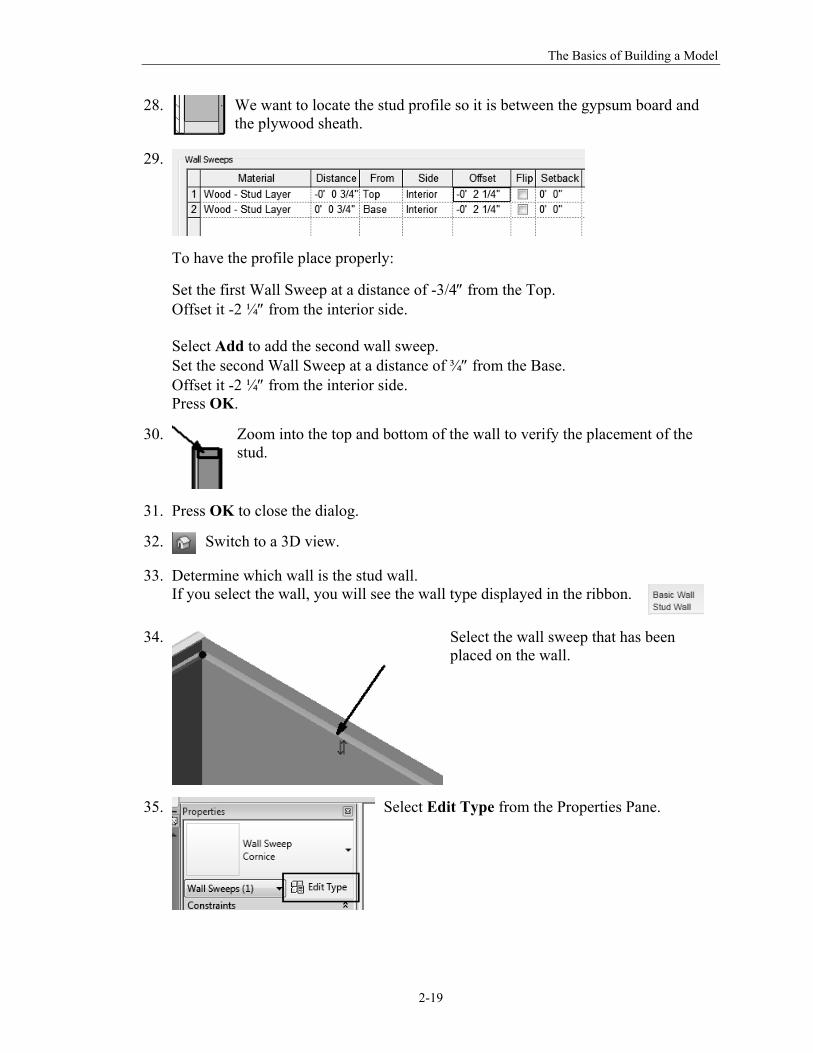
29.
To have the profile place properly:
Set the first Wall Sweep at a distance of -3/4 from the Top. Offset it -2 ¼ from the interior side. Select Add to add the second wall sweep. Set the second Wall Sweep at a distance of ¾ from the Base. Offset it -2 ¼ from the interior side. Press OK.
30.
Zoom into the top and bottom of the wall to verify the placement of the stud.
31. Press OK to close the dialog.
32.
Switch to a 3D view.
33. Determine which wall is the stud wall. If you select the wall, you will see the wall type displayed in the ribbon.
34.
Select the wall sweep that has been placed on the wall.
35.
Select Edit Type from the Properties Pane.
The Unofficial Revit 2012 Certification Exam Guide
2-20
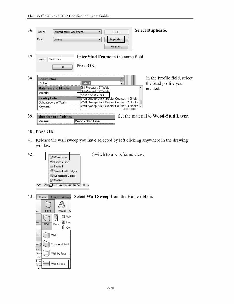
36.
Select Duplicate.
37.
Enter Stud Frame in the name field.
Press OK.
38.
In the Profile field, select the Stud profile you created.
39.
Set the material to Wood-Stud Layer.
40. Press OK.
41. Release the wall sweep you have selected by left clicking anywhere in the drawing window.
42.
Switch to a wireframe view.
43.
Select Wall Sweep from the Home ribbon.
The Basics of Building a Model
2-21
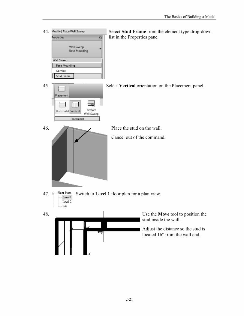
44.
Select Stud Frame from the element type drop-down list in the Properties pane.
45.
Select Vertical orientation on the Placement panel.
46.
Place the stud on the wall.
Cancel out of the command.
47.
Switch to Level 1 floor plan for a plan view.
48.
Use the Move tool to position the stud inside the wall.
Adjust the distance so the stud is located 16 from the wall end.
The Unofficial Revit 2012 Certification Exam Guide
2-22
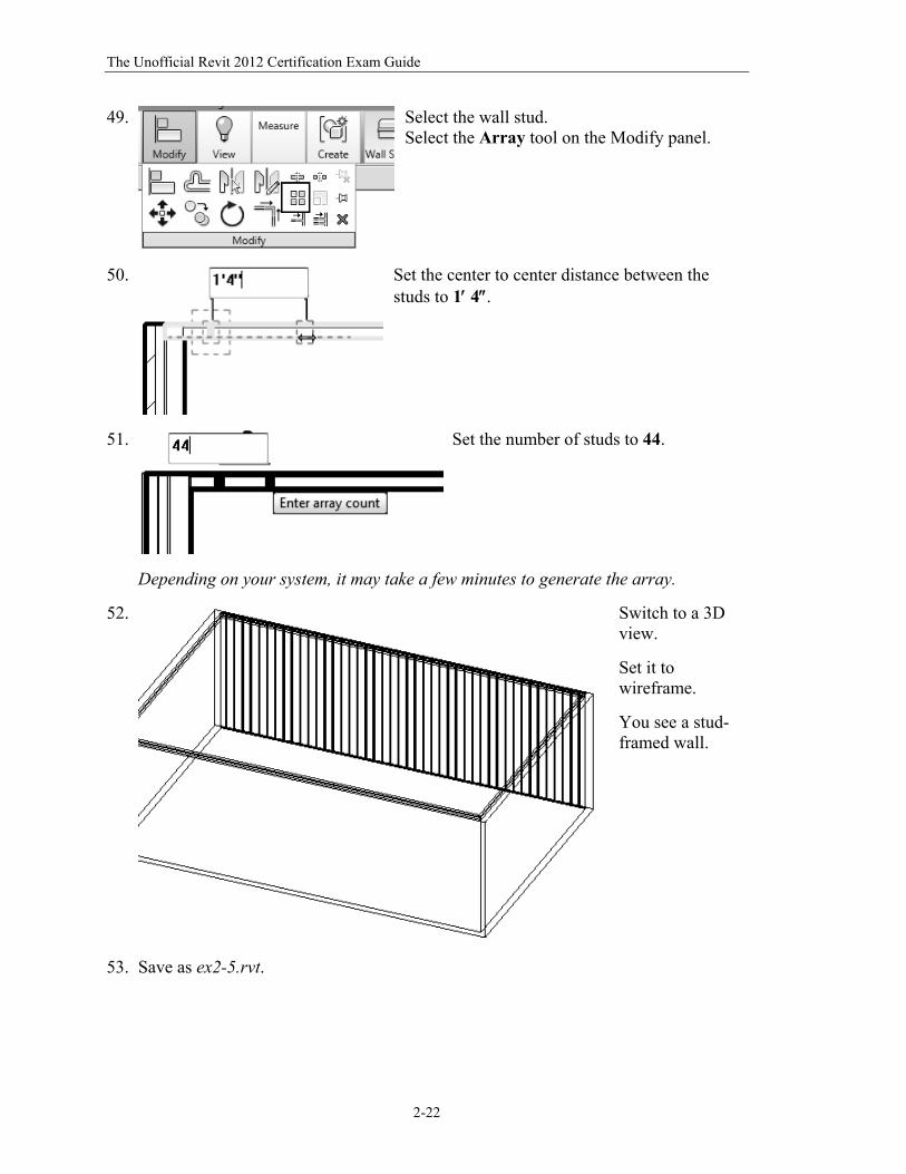
49.
Select the wall stud. Select the Array tool on the Modify panel.
50.
Set the center to center distance between the studs to 1 4.
51.
Set the number of studs to 44.
Depending on your system, it may take a few minutes to generate the array.
52.
Switch to a 3D view.
Set it to wireframe.
You see a stud-framed wall.
53. Save as ex2-5.rvt.
The Basics of Building a Model
2-23
Command Exercise
Exercise 2-6 – Stacked Walls
Drawing Name: i_stacked_walls.rvt Estimated Time to Completion: 60 Minutes Scope
Defining a stacked wall structure
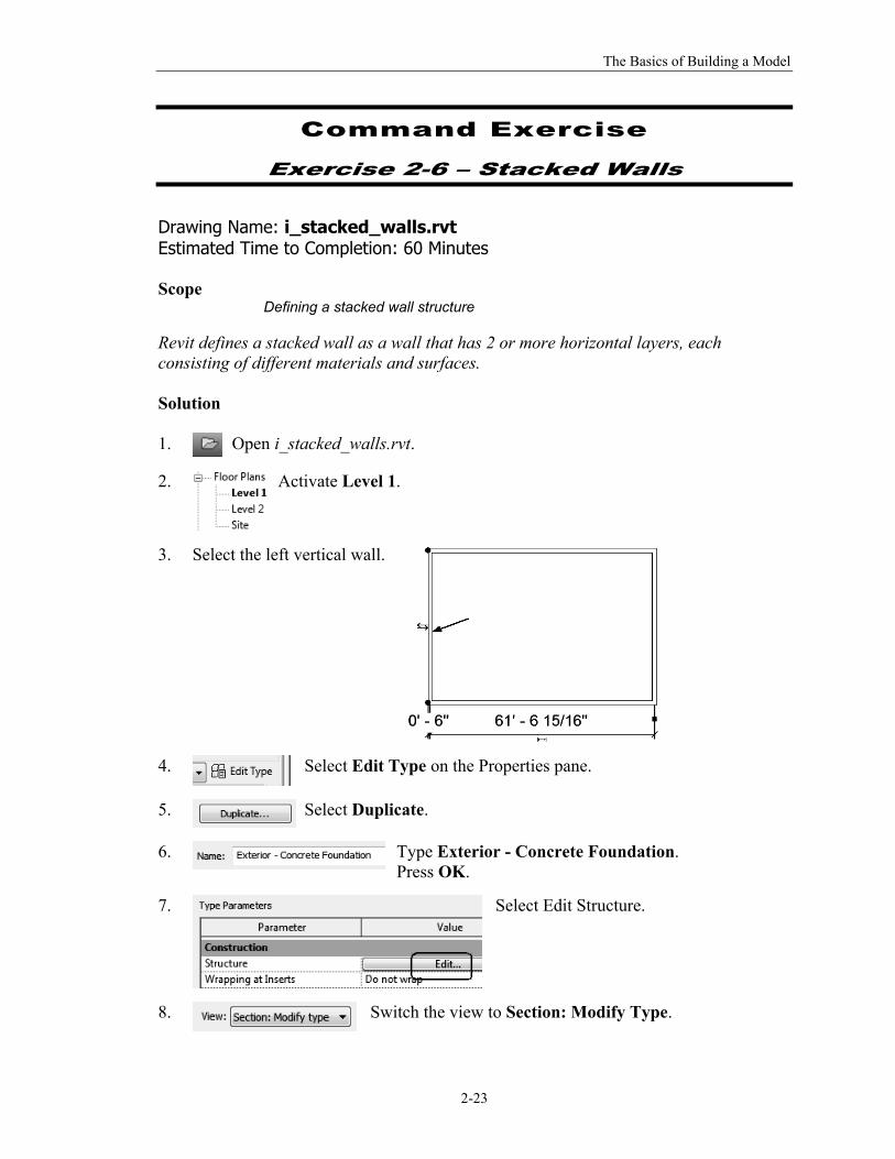
Revit defines a stacked wall as a wall that has 2 or more horizontal layers, each consisting of different materials and surfaces. Solution 1.
Open i_stacked_walls.rvt.
2.
Activate Level 1.
3. Select the left vertical wall.
4.
Select Edit Type on the Properties pane.
5.
Select Duplicate.
6.
Type Exterior - Concrete Foundation. Press OK.
7.
Select Edit Structure.
8.
Switch the view to Section: Modify Type.
The Unofficial Revit 2012 Certification Exam Guide
2-24
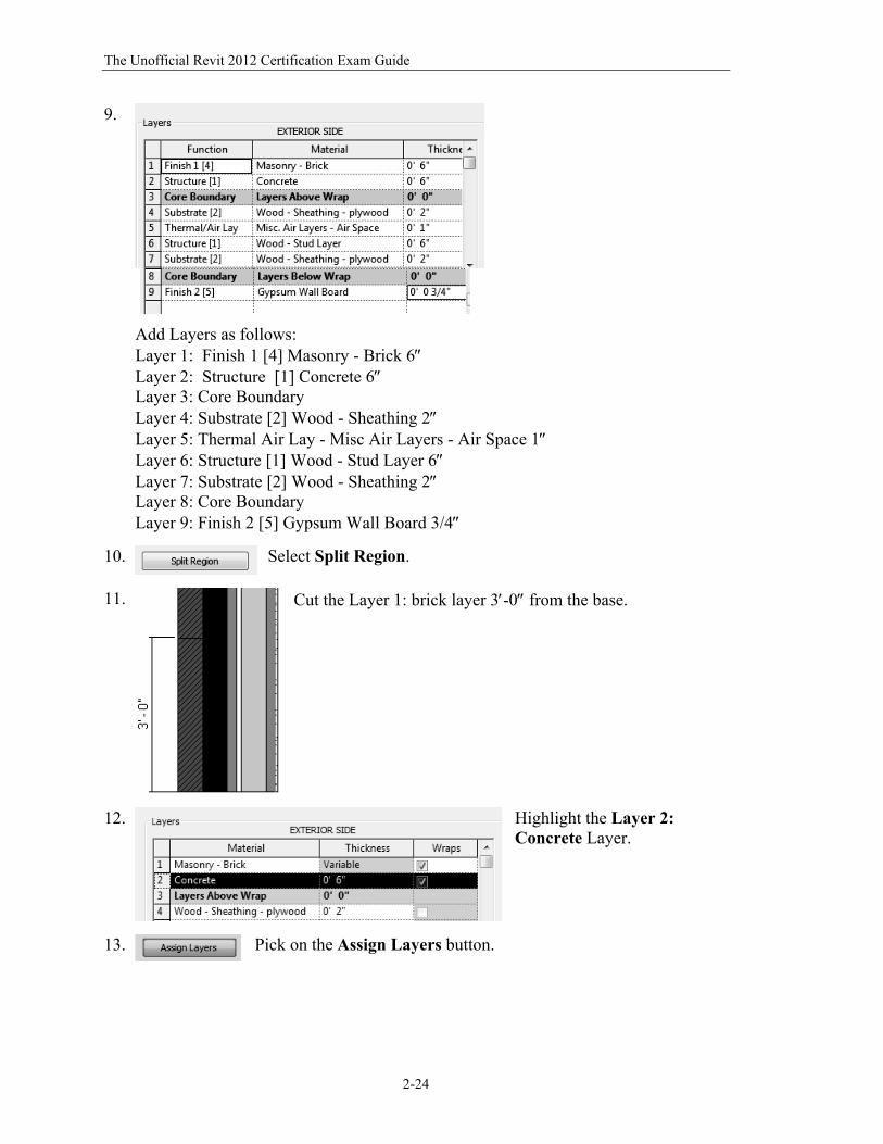
9.
Add Layers as follows: Layer 1: Finish 1 [4] Masonry - Brick 6 Layer 2: Structure [1] Concrete 6 Layer 3: Core Boundary Layer 4: Substrate [2] Wood - Sheathing 2 Layer 5: Thermal Air Lay - Misc Air Layers - Air Space 1 Layer 6: Structure [1] Wood - Stud Layer 6 Layer 7: Substrate [2] Wood - Sheathing 2 Layer 8: Core Boundary Layer 9: Finish 2 [5] Gypsum Wall Board 3/4
10.
Select Split Region.
11.
Cut the Layer 1: brick layer 3-0 from the base.
12.
Highlight the Layer 2: Concrete Layer.
13.
Pick on the Assign Layers button.
The Basics of Building a Model
2-25
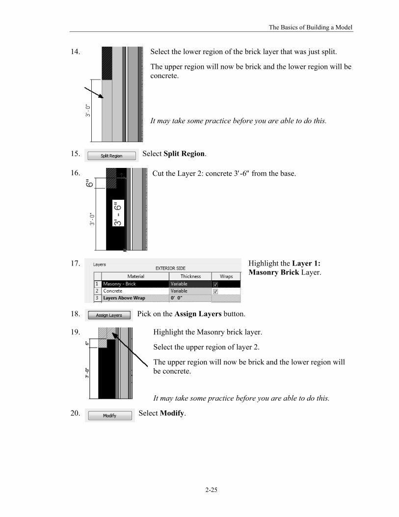
14.
Select the lower region of the brick layer that was just split.
The upper region will now be brick and the lower region will be concrete. It may take some practice before you are able to do this.
15.
Select Split Region.
16.
Cut the Layer 2: concrete 3-6 from the base.
17.
Highlight the Layer 1: Masonry Brick Layer.
18.
Pick on the Assign Layers button.
19.
Highlight the Masonry brick layer.
Select the upper region of layer 2.
The upper region will now be brick and the lower region will be concrete. It may take some practice before you are able to do this.
20.
Select Modify.
The Unofficial Revit 2012 Certification Exam Guide
2-26
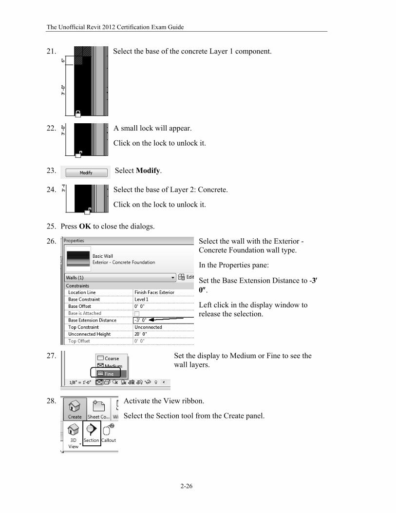
21.
Select the base of the concrete Layer 1 component.
22.
A small lock will appear.
Click on the lock to unlock it.
23.
Select Modify.
24.
Select the base of Layer 2: Concrete.
Click on the lock to unlock it.
25. Press OK to close the dialogs.
26.
Select the wall with the Exterior -Concrete Foundation wall type.
In the Properties pane:
Set the Base Extension Distance to -3 0.
Left click in the display window to release the selection.
27.
Set the display to Medium or Fine to see the wall layers.
28.
Activate the View ribbon.
Select the Section tool from the Create panel.
The Basics of Building a Model
2-27
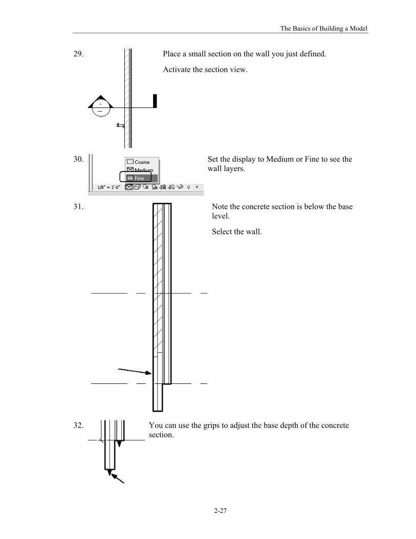
29.
Place a small section on the wall you just defined.
Activate the section view.
30.
Set the display to Medium or Fine to see the wall layers.
31.
Note the concrete section is below the base level.
Select the wall.
32.
You can use the grips to adjust the base depth of the concrete section.
The Unofficial Revit 2012 Certification Exam Guide
2-28
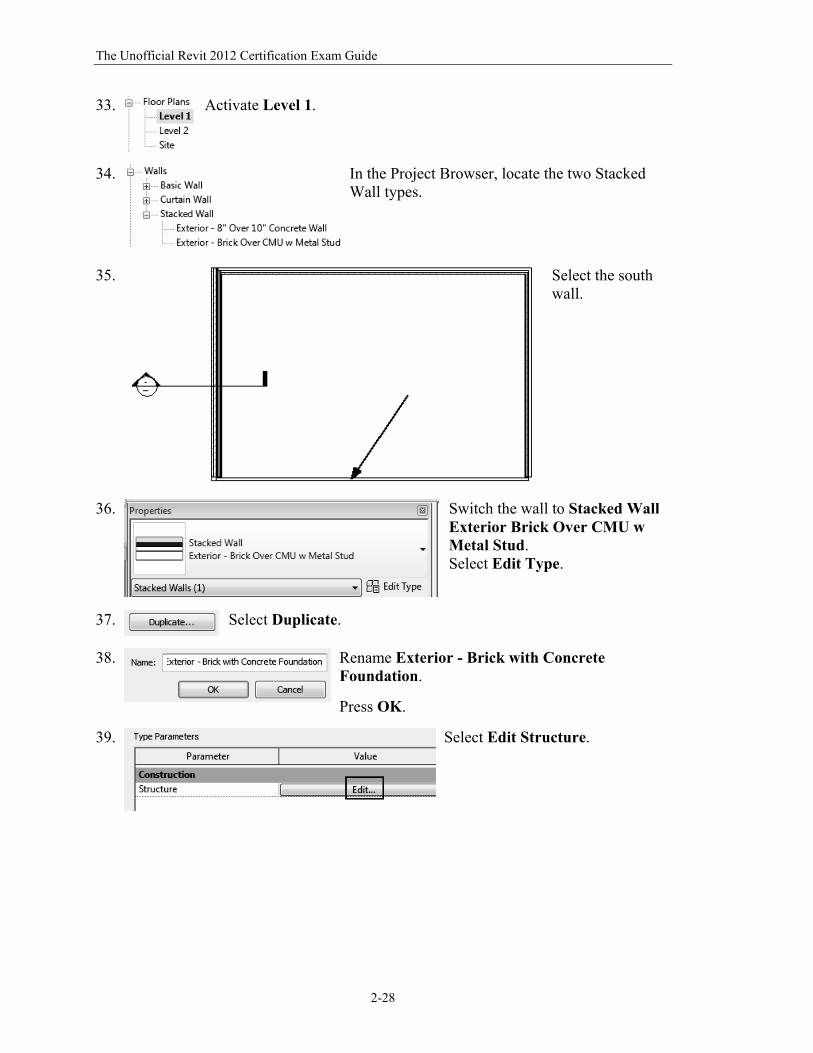
33.
Activate Level 1.
34.
In the Project Browser, locate the two Stacked Wall types.
35.
Select the south wall.
36.
Switch the wall to Stacked Wall Exterior Brick Over CMU w Metal Stud. Select Edit Type.
37.
Select Duplicate.
38.
Rename Exterior - Brick with Concrete Foundation.
Press OK.
39.
Select Edit Structure.
The Basics of Building a Model
2-29
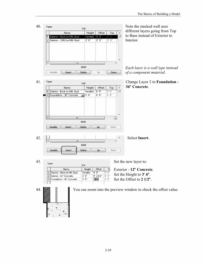
40.
Note the stacked wall uses different layers going from Top to Base instead of Exterior to Interior. Each layer is a wall type instead of a component material.
41.
Change Layer 2 to Foundation - 36 Concrete.
42.
Select Insert.
43.
Set the new layer to:
Exterior - 12 Concrete. Set the Height to 3 6. Set the Offset to 2 1/2.
44. You can zoom into the preview window to check the offset value.
The Unofficial Revit 2012 Certification Exam Guide
2-30
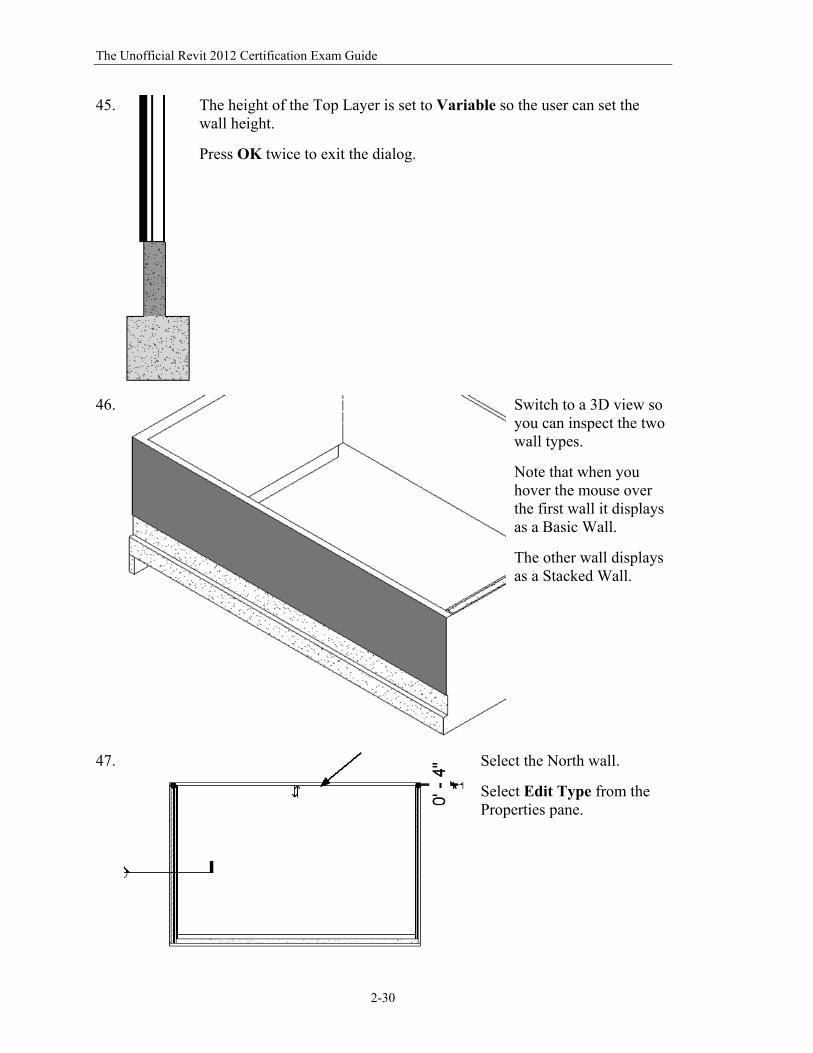
45.
The height of the Top Layer is set to Variable so the user can set the wall height.
Press OK twice to exit the dialog.
46.
Switch to a 3D view so you can inspect the two wall types.
Note that when you hover the mouse over the first wall it displays as a Basic Wall.
The other wall displays as a Stacked Wall.
47. Select the North wall.
Select Edit Type from the Properties pane.
The Basics of Building a Model
2-31
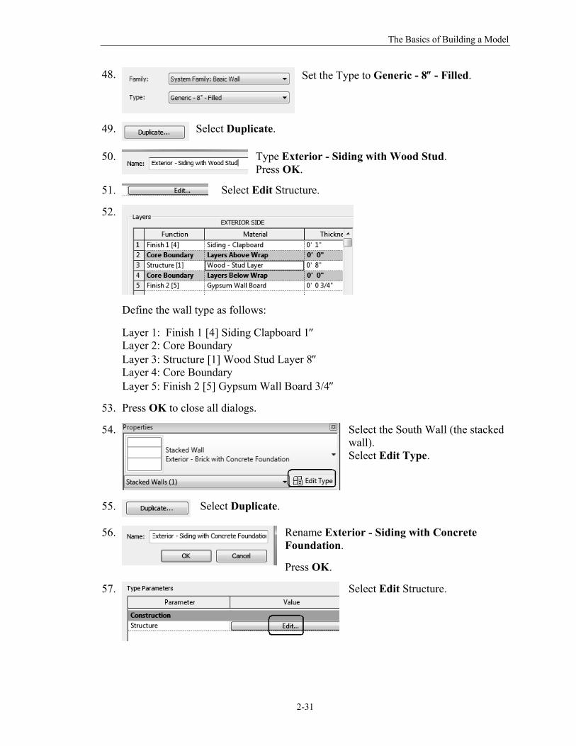
48.
Set the Type to Generic - 8 - Filled.
49.
Select Duplicate.
50.
Type Exterior - Siding with Wood Stud. Press OK.
51. Select Edit Structure.
52.
Define the wall type as follows:
Layer 1: Finish 1 [4] Siding Clapboard 1 Layer 2: Core Boundary Layer 3: Structure [1] Wood Stud Layer 8 Layer 4: Core Boundary Layer 5: Finish 2 [5] Gypsum Wall Board 3/4
53. Press OK to close all dialogs.
54.
Select the South Wall (the stacked wall). Select Edit Type.
55.
Select Duplicate.
56. Rename Exterior - Siding with Concrete Foundation.
Press OK.
57.
Select Edit Structure.
The Unofficial Revit 2012 Certification Exam Guide
2-32
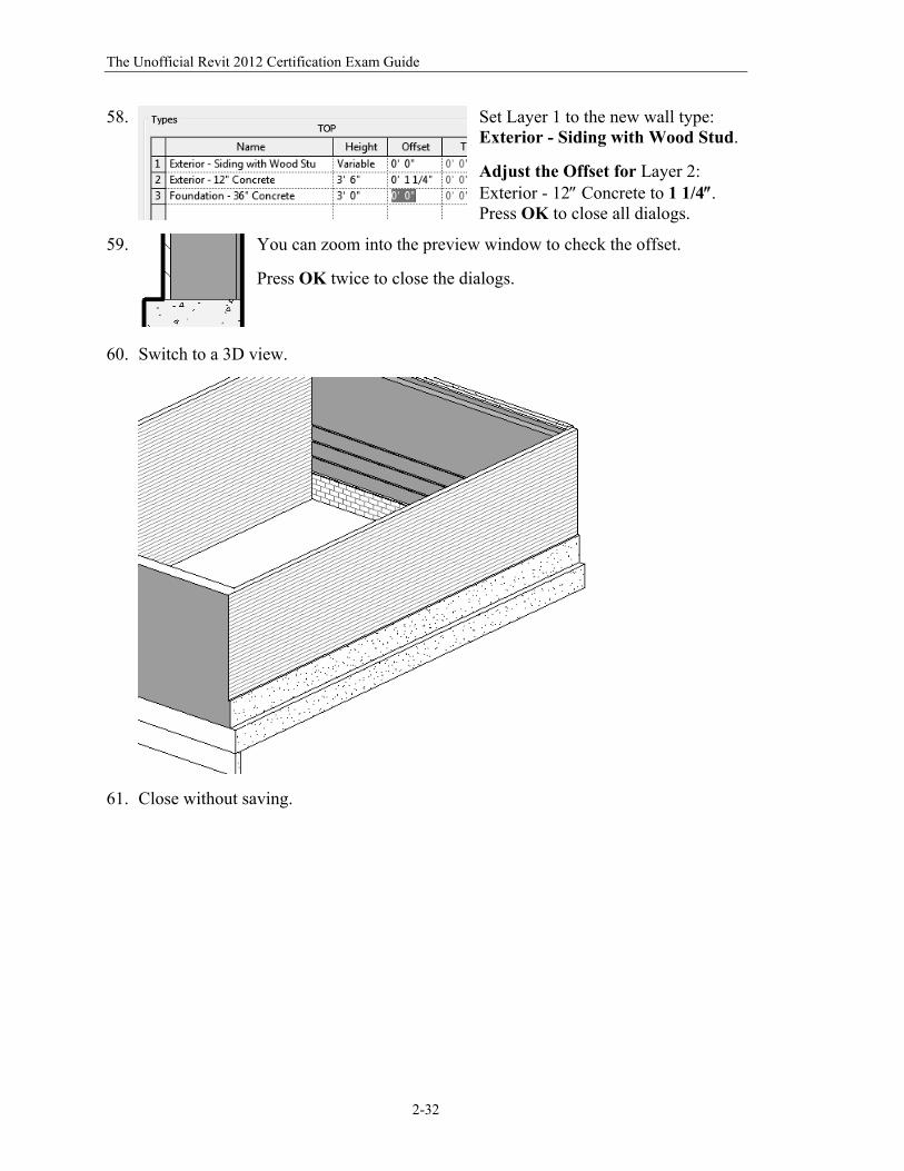
58.
Set Layer 1 to the new wall type: Exterior - Siding with Wood Stud.
Adjust the Offset for Layer 2: Exterior - 12 Concrete to 1 1/4. Press OK to close all dialogs.
59.
You can zoom into the preview window to check the offset.
Press OK twice to close the dialogs.
60. Switch to a 3D view.
61. Close without saving.
The Basics of Building a Model
2-33
Command Exercise
Exercise 2-7 – Chained Walls
Drawing Name: i-walls.rvt Estimated Time to Completion: 10 Minutes Scope
Using TAB to select walls. Using CTRL to copy selected items. Using SHIFT to move selected items.
Solution 1.
Open i-walls.rvt.
2.
Select the Wall tool from the Home ribbon.
3.
Select the Brick and CMU on MTL. Stud wall style on the Properties pane.
4.
Enable Chain.
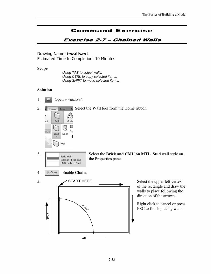
5.
Select the upper left vertex of the rectangle and draw the walls to place following the direction of the arrows.
Right click to cancel or press ESC to finish placing walls.
The Unofficial Revit 2012 Certification Exam Guide
2-34
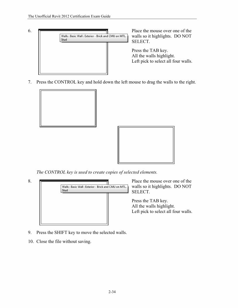
6.
Place the mouse over one of the walls so it highlights. DO NOT SELECT.
Press the TAB key. All the walls highlight. Left pick to select all four walls.
7. Press the CONTROL key and hold down the left mouse to drag the walls to the right.
The CONTROL key is used to create copies of selected elements.
8.
Place the mouse over one of the walls so it highlights. DO NOT SELECT.
Press the TAB key. All the walls highlight. Left pick to select all four walls.
9. Press the SHIFT key to move the selected walls.
10. Close the file without saving.
The Basics of Building a Model
2-35
Command Exercise
Exercise 2-8 – Dividing a Wall into Parts
Drawing Name: wall_parts.rvt Estimated Time to Completion: 45 Minutes Scope
Use of parts to apply materials to a wall
Solution 1.
Activate the South elevation view.
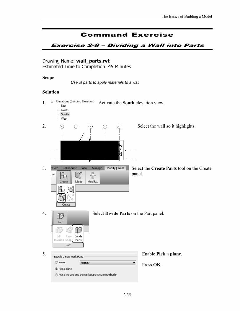
2.
Select the wall so it highlights.
3.
Select the Create Parts tool on the Create panel.
4.
Select Divide Parts on the Part panel.
5.
Enable Pick a plane. Press OK.
The Unofficial Revit 2012 Certification Exam Guide
2-36
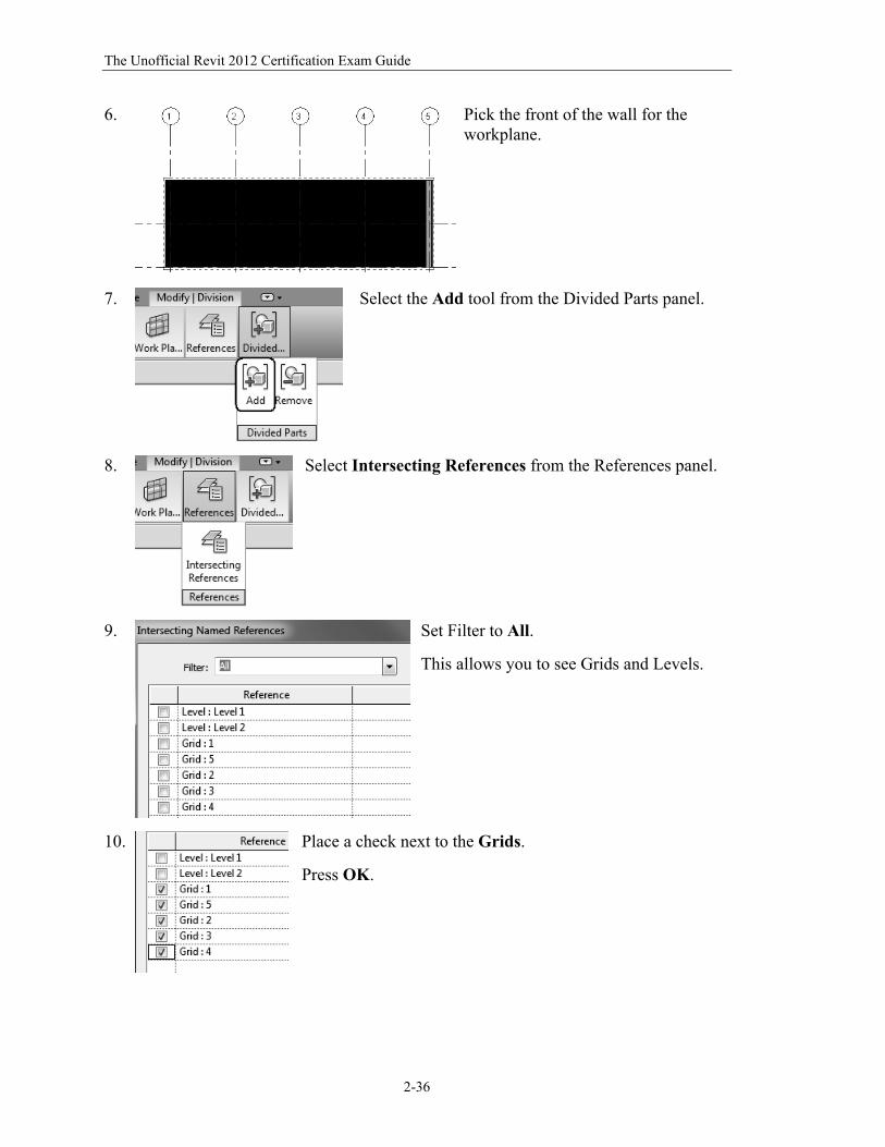
6.
Pick the front of the wall for the workplane.
7.
Select the Add tool from the Divided Parts panel.
8.
Select Intersecting References from the References panel.
9.
Set Filter to All.
This allows you to see Grids and Levels.
10.
Place a check next to the Grids.
Press OK.
The Basics of Building a Model
2-37
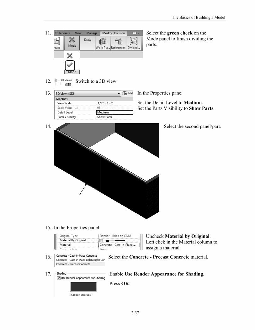
11.
Select the green check on the Mode panel to finish dividing the parts.
12.
Switch to a 3D view.
13.
In the Properties pane:
Set the Detail Level to Medium. Set the Parts Visibility to Show Parts.
14.
Select the second panel/part.
15. In the Properties panel:
Uncheck Material by Original. Left click in the Material column to assign a material.
16.
Select the Concrete - Precast Concrete material.
17. Enable Use Render Appearance for Shading.
Press OK.
The Unofficial Revit 2012 Certification Exam Guide
2-38
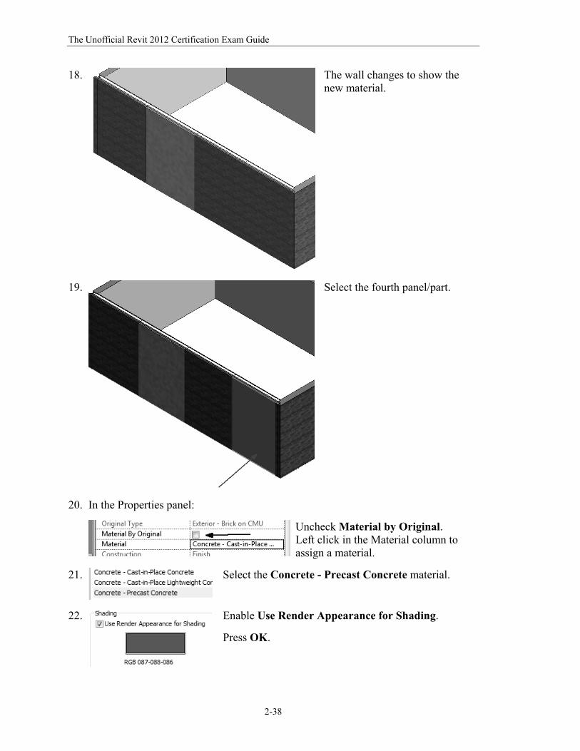
18.
The wall changes to show the new material.
19.
Select the fourth panel/part.
20. In the Properties panel:
Uncheck Material by Original. Left click in the Material column to assign a material.
21.
Select the Concrete - Precast Concrete material.
22.
Enable Use Render Appearance for Shading.
Press OK.
The Basics of Building a Model
2-39
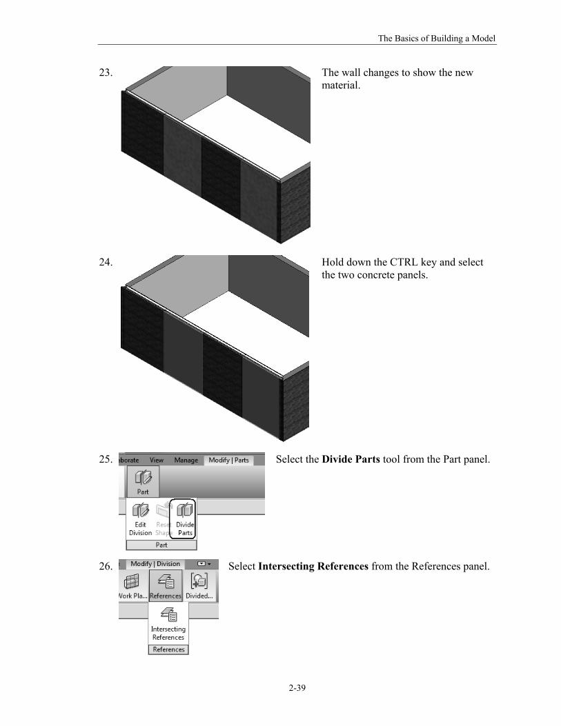
23.
The wall changes to show the new material.
24.
Hold down the CTRL key and select the two concrete panels.
25.
Select the Divide Parts tool from the Part panel.
26.
Select Intersecting References from the References panel.
The Unofficial Revit 2012 Certification Exam Guide
2-40
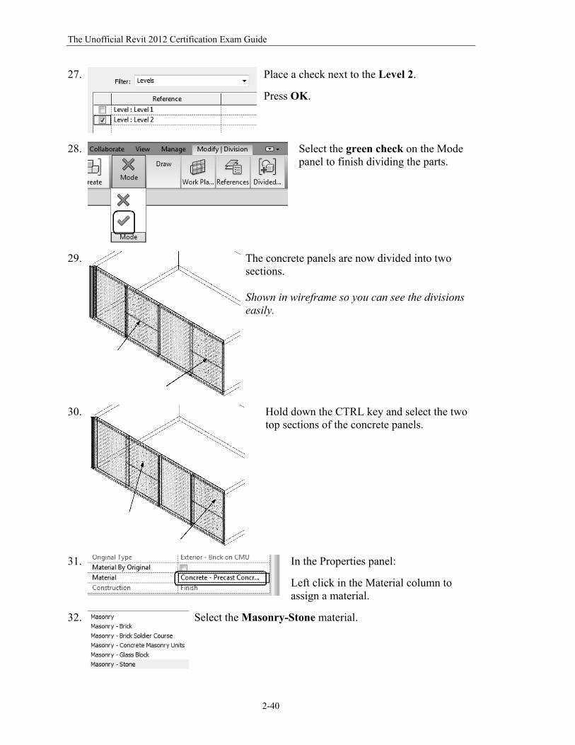
27.
Place a check next to the Level 2.
Press OK.
28.
Select the green check on the Mode panel to finish dividing the parts.
29.
The concrete panels are now divided into two sections. Shown in wireframe so you can see the divisions easily.
30.
Hold down the CTRL key and select the two top sections of the concrete panels.
31.
In the Properties panel:
Left click in the Material column to assign a material.
32. Select the Masonry-Stone material.
The Basics of Building a Model
2-41
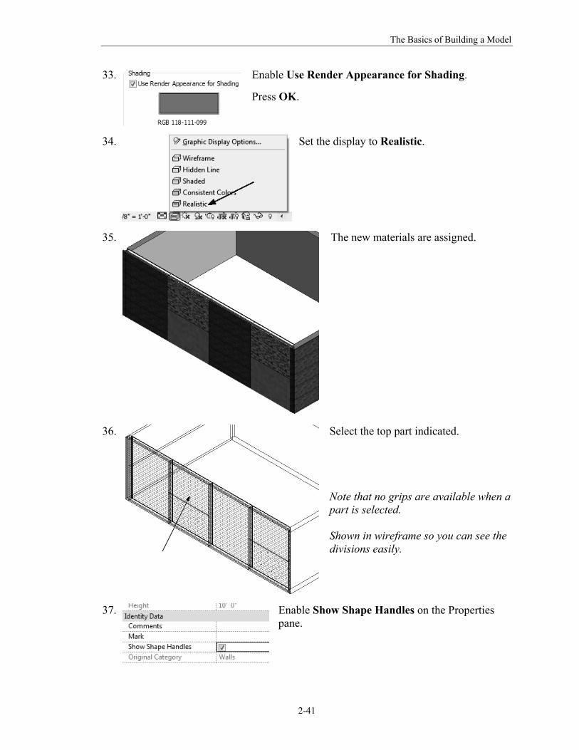
33.
Enable Use Render Appearance for Shading.
Press OK.
34.
Set the display to Realistic.
35.
The new materials are assigned.
36.
Select the top part indicated. Note that no grips are available when a part is selected. Shown in wireframe so you can see the divisions easily.
37.
Enable Show Shape Handles on the Properties pane.
The Unofficial Revit 2012 Certification Exam Guide
2-42
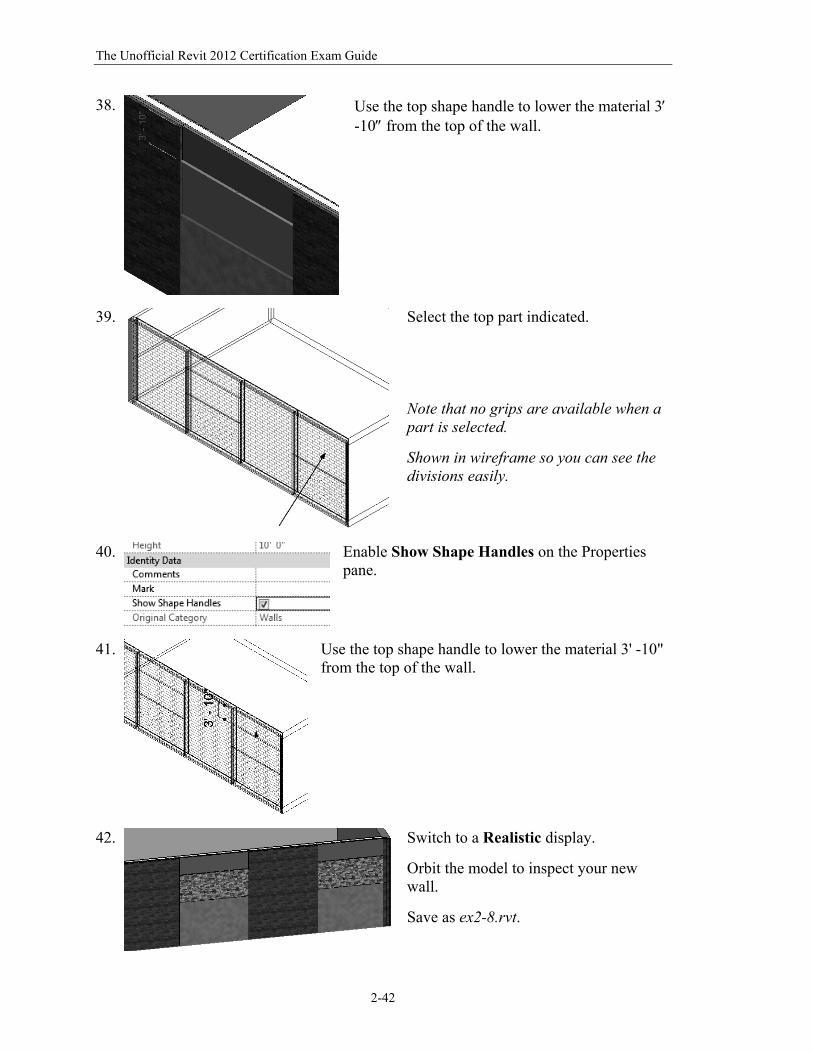
38.
Use the top shape handle to lower the material 3 -10 from the top of the wall.
39.
Select the top part indicated. Note that no grips are available when a part is selected. Shown in wireframe so you can see the divisions easily.
40.
Enable Show Shape Handles on the Properties pane.
41.
Use the top shape handle to lower the material 3' -10" from the top of the wall.
42. Switch to a Realistic display.
Orbit the model to inspect your new wall.
Save as ex2-8.rvt.
The Basics of Building a Model
2-43
Command Exercise
Exercise 2-9 – Creating an In-Place Mass
Drawing Name: in_place_mass.rvt Estimated Time to Completion: 60 Minutes Scope
Use of in-place masses to create a conceptual model
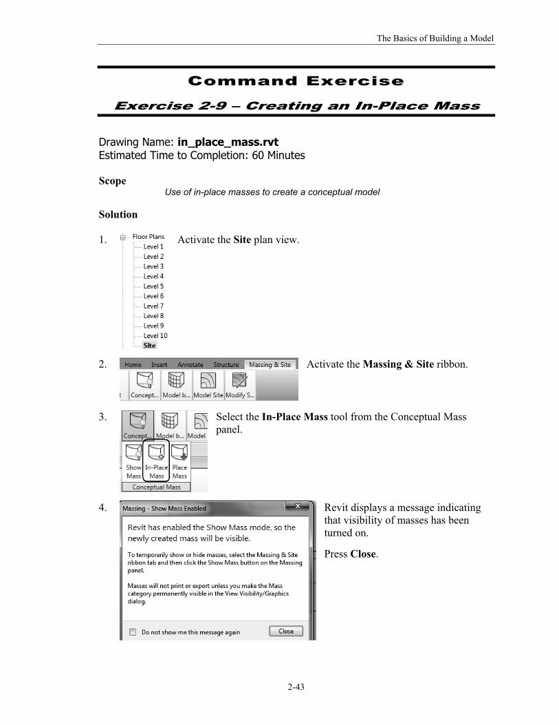
Solution 1.
Activate the Site plan view.
2.
Activate the Massing & Site ribbon.
3.
Select the In-Place Mass tool from the Conceptual Mass panel.
4. Revit displays a message indicating that visibility of masses has been turned on.
Press Close.
The Unofficial Revit 2012 Certification Exam Guide
2-44
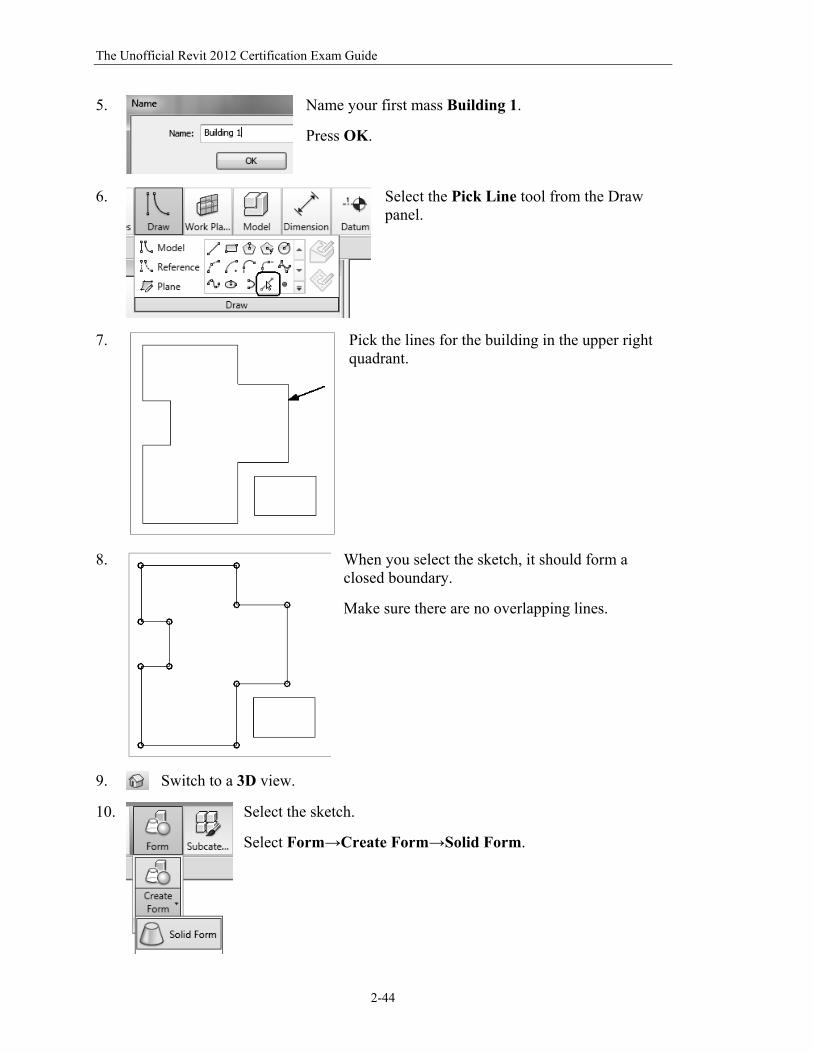
5.
Name your first mass Building 1.
Press OK.
6.
Select the Pick Line tool from the Draw panel.
7.
Pick the lines for the building in the upper right quadrant.
8.
When you select the sketch, it should form a closed boundary.
Make sure there are no overlapping lines.
9.
Switch to a 3D view.
10.
Select the sketch.
Select Form→Create Form→Solid Form.
The Basics of Building a Model
2-45
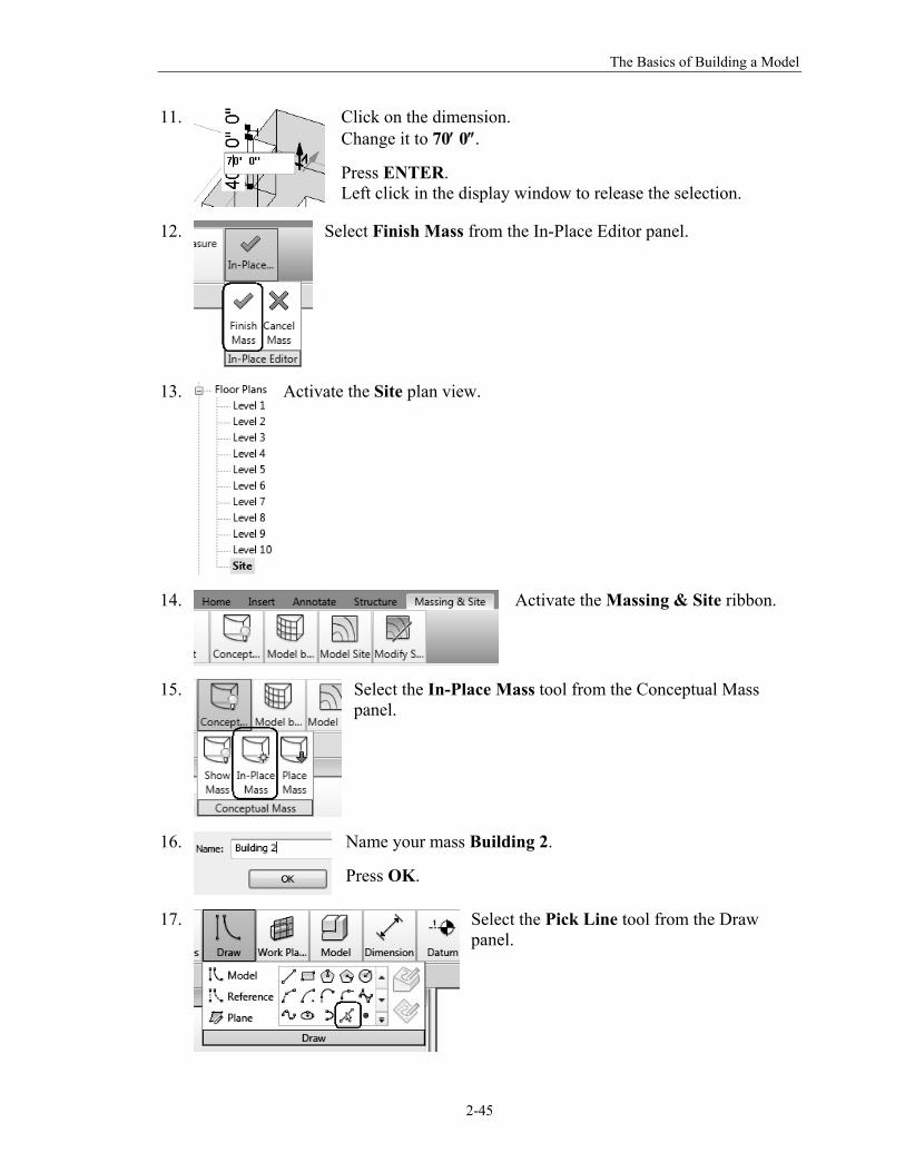
11.
Click on the dimension. Change it to 70 0.
Press ENTER. Left click in the display window to release the selection.
12.
Select Finish Mass from the In-Place Editor panel.
13.
Activate the Site plan view.
14.
Activate the Massing & Site ribbon.
15.
Select the In-Place Mass tool from the Conceptual Mass panel.
16.
Name your mass Building 2.
Press OK.
17.
Select the Pick Line tool from the Draw panel.
The Unofficial Revit 2012 Certification Exam Guide
2-46
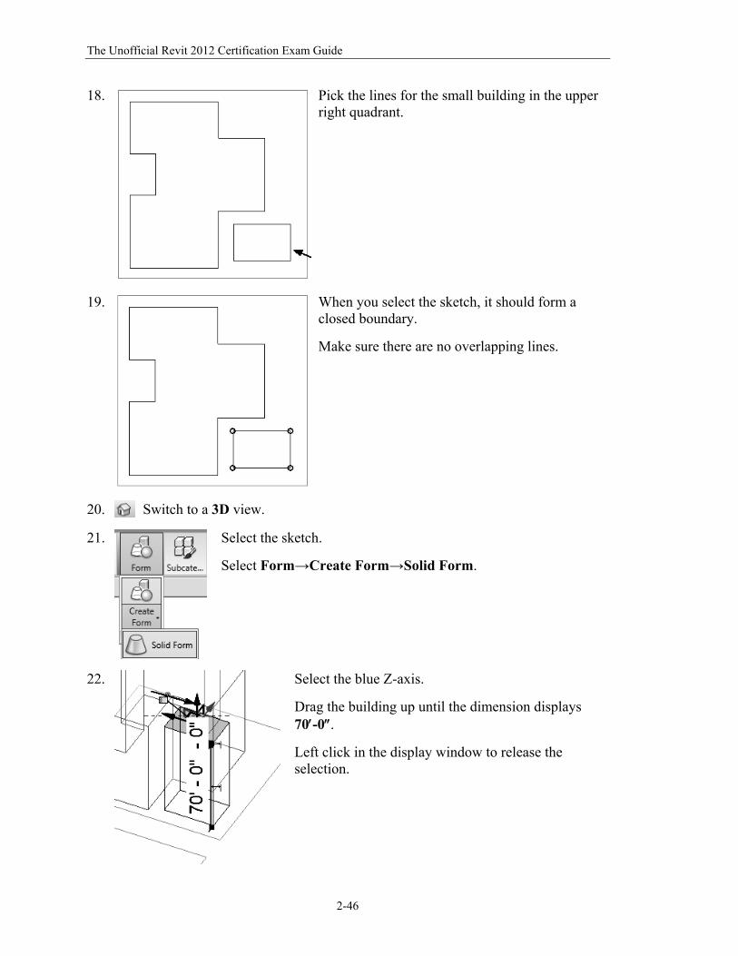
18.
Pick the lines for the small building in the upper right quadrant.
19.
When you select the sketch, it should form a closed boundary.
Make sure there are no overlapping lines.
20.
Switch to a 3D view.
21.
Select the sketch.
Select Form→Create Form→Solid Form.
22.
Select the blue Z-axis.
Drag the building up until the dimension displays 70-0.
Left click in the display window to release the selection.
The Basics of Building a Model
2-47
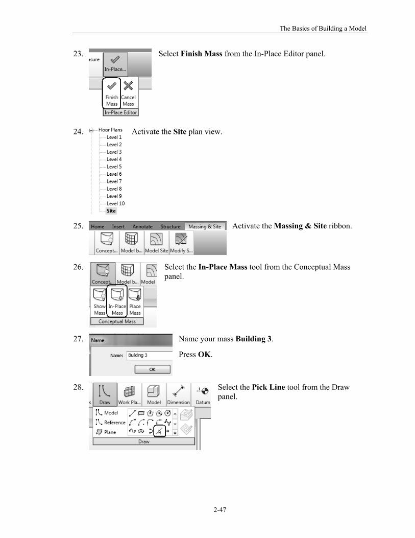
23.
Select Finish Mass from the In-Place Editor panel.
24.
Activate the Site plan view.
25.
Activate the Massing & Site ribbon.
26.
Select the In-Place Mass tool from the Conceptual Mass panel.
27.
Name your mass Building 3.
Press OK.
28.
Select the Pick Line tool from the Draw panel.
The Unofficial Revit 2012 Certification Exam Guide
2-48
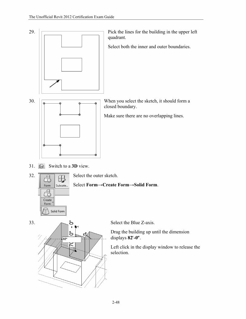
29.
Pick the lines for the building in the upper left quadrant.
Select both the inner and outer boundaries.
30.
When you select the sketch, it should form a closed boundary.
Make sure there are no overlapping lines.
31.
Switch to a 3D view.
32.
Select the outer sketch.
Select Form→Create Form→Solid Form.
33. Select the Blue Z-axis.
Drag the building up until the dimension displays 82-0.
Left click in the display window to release the selection.
The Basics of Building a Model
2-49
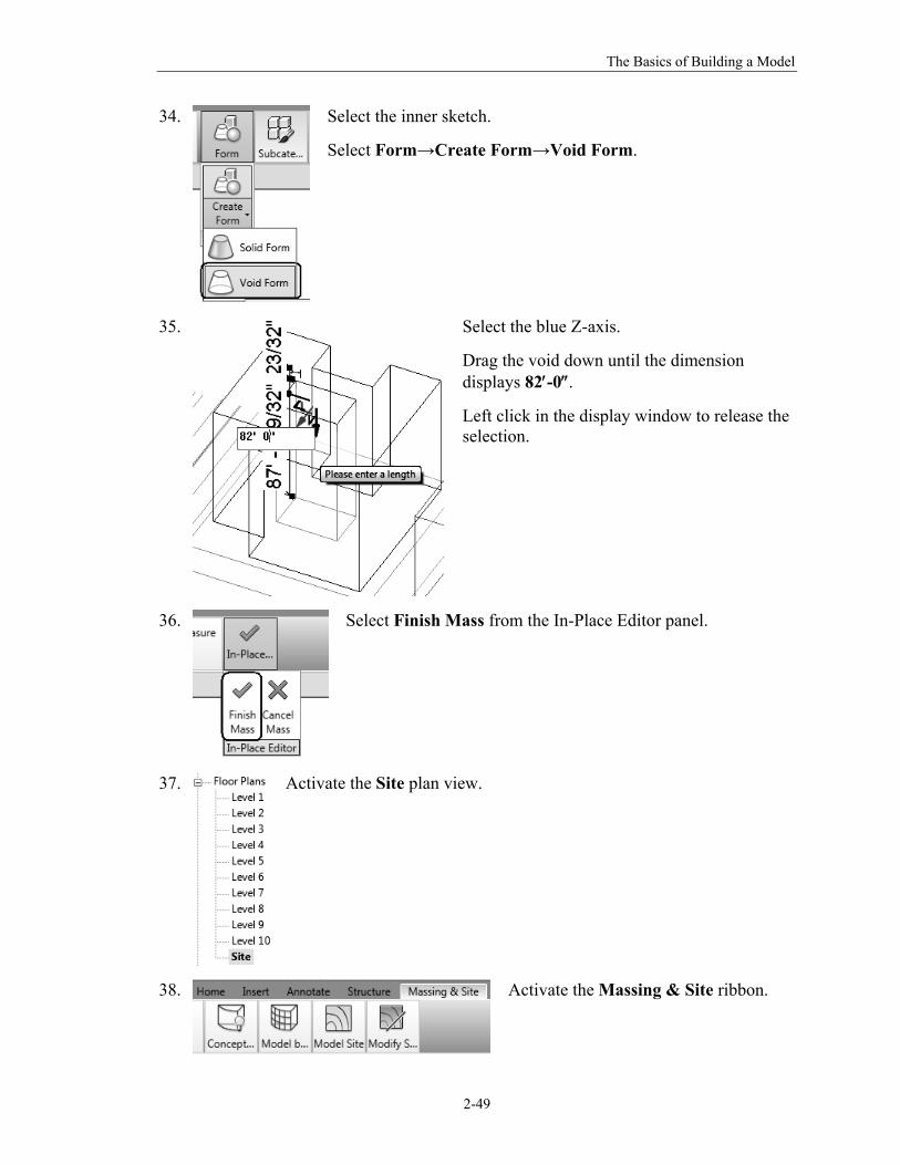
34.
Select the inner sketch.
Select Form→Create Form→Void Form.
35.
Select the blue Z-axis.
Drag the void down until the dimension displays 82-0.
Left click in the display window to release the selection.
36.
Select Finish Mass from the In-Place Editor panel.
37.
Activate the Site plan view.
38.
Activate the Massing & Site ribbon.
The Unofficial Revit 2012 Certification Exam Guide
2-50
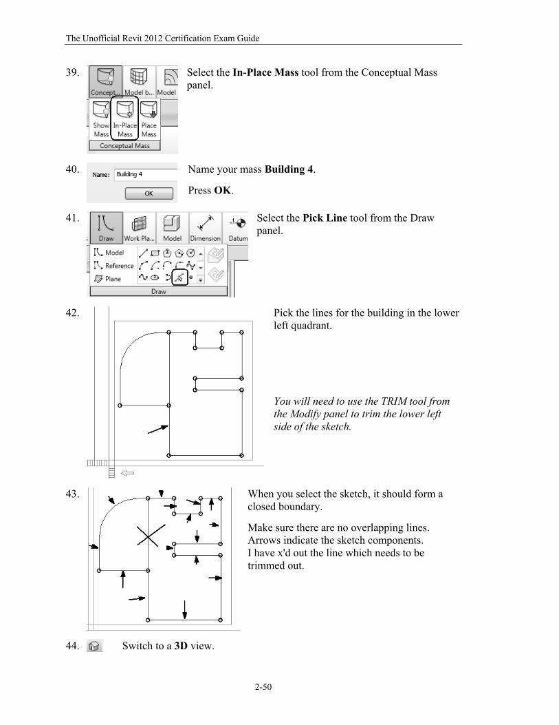
39.
Select the In-Place Mass tool from the Conceptual Mass panel.
40.
Name your mass Building 4.
Press OK.
41.
Select the Pick Line tool from the Draw panel.
42.
Pick the lines for the building in the lower left quadrant. You will need to use the TRIM tool from the Modify panel to trim the lower left side of the sketch.
43.
When you select the sketch, it should form a closed boundary.
Make sure there are no overlapping lines. Arrows indicate the sketch components. I have x'd out the line which needs to be trimmed out.
44. Switch to a 3D view.
The Basics of Building a Model
2-51
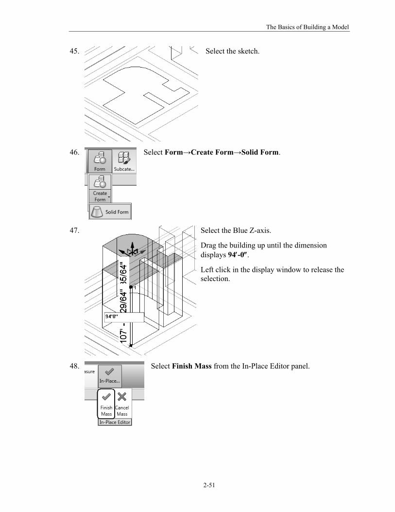
45.
Select the sketch.
46.
Select Form→Create Form→Solid Form.
47.
Select the Blue Z-axis.
Drag the building up until the dimension displays 94-0.
Left click in the display window to release the selection.
48.
Select Finish Mass from the In-Place Editor panel.
The Unofficial Revit 2012 Certification Exam Guide
2-52
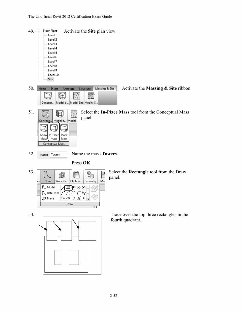
49.
Activate the Site plan view.
50.
Activate the Massing & Site ribbon.
51.
Select the In-Place Mass tool from the Conceptual Mass panel.
52.
Name the mass Towers.
Press OK.
53.
Select the Rectangle tool from the Draw panel.
54.
Trace over the top three rectangles in the fourth quadrant.
The Basics of Building a Model
2-53
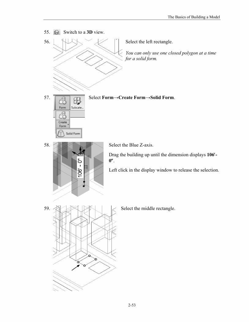
55.
Switch to a 3D view.
56.
Select the left rectangle. You can only use one closed polygon at a time for a solid form.
57.
Select Form→Create Form→Solid Form.
58.
Select the Blue Z-axis.
Drag the building up until the dimension displays 106-0.
Left click in the display window to release the selection.
59.
Select the middle rectangle.
The Unofficial Revit 2012 Certification Exam Guide
2-54
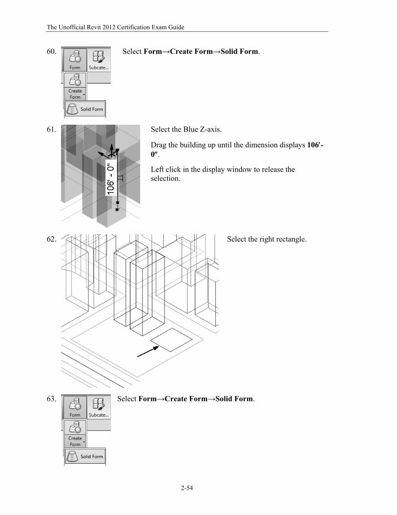
60.
Select Form→Create Form→Solid Form.
61.
Select the Blue Z-axis.
Drag the building up until the dimension displays 106-0.
Left click in the display window to release the selection.
62.
Select the right rectangle.
63.
Select Form→Create Form→Solid Form.
The Basics of Building a Model
2-55
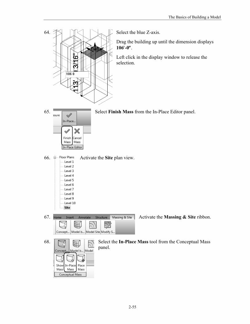
64.
Select the blue Z-axis.
Drag the building up until the dimension displays 106-0.
Left click in the display window to release the selection.
65.
Select Finish Mass from the In-Place Editor panel.
66.
Activate the Site plan view.
67.
Activate the Massing & Site ribbon.
68.
Select the In-Place Mass tool from the Conceptual Mass panel.

The Unofficial Revit 2012 Certification Exam Guide
2-56
69.
Name the mass Building 5.
Press OK.
70.
Select the Pick Line tool from the Draw panel.
71.
Pick the lines for the sketch in the lower right quadrant.
Use Draw Line to complete the sketch.
Use the Rectangle tool to create two sketches for the internal rectangles. These will be voids.
72. When you select one of the lines of the sketch, you should see the entire sketch highlight. If you don’t see a continuous loop, there are either missing lines or overlapping/ duplicate lines. Check the sketch for overlapping lines by deleting a line, then click UNDO if it is not a duplicate.
The Basics of Building a Model
2-57
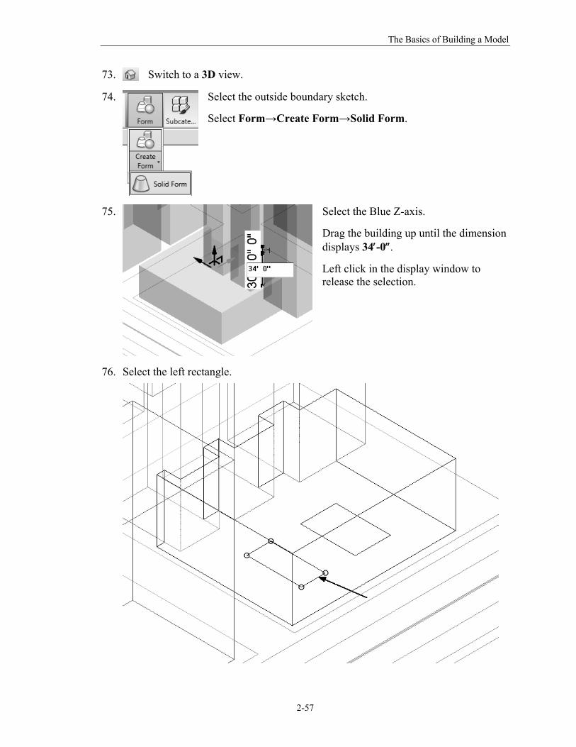
73.
Switch to a 3D view.
74.
Select the outside boundary sketch.
Select Form→Create Form→Solid Form.
75.
Select the Blue Z-axis.
Drag the building up until the dimension displays 34-0.
Left click in the display window to release the selection.
76. Select the left rectangle.
The Unofficial Revit 2012 Certification Exam Guide
2-58
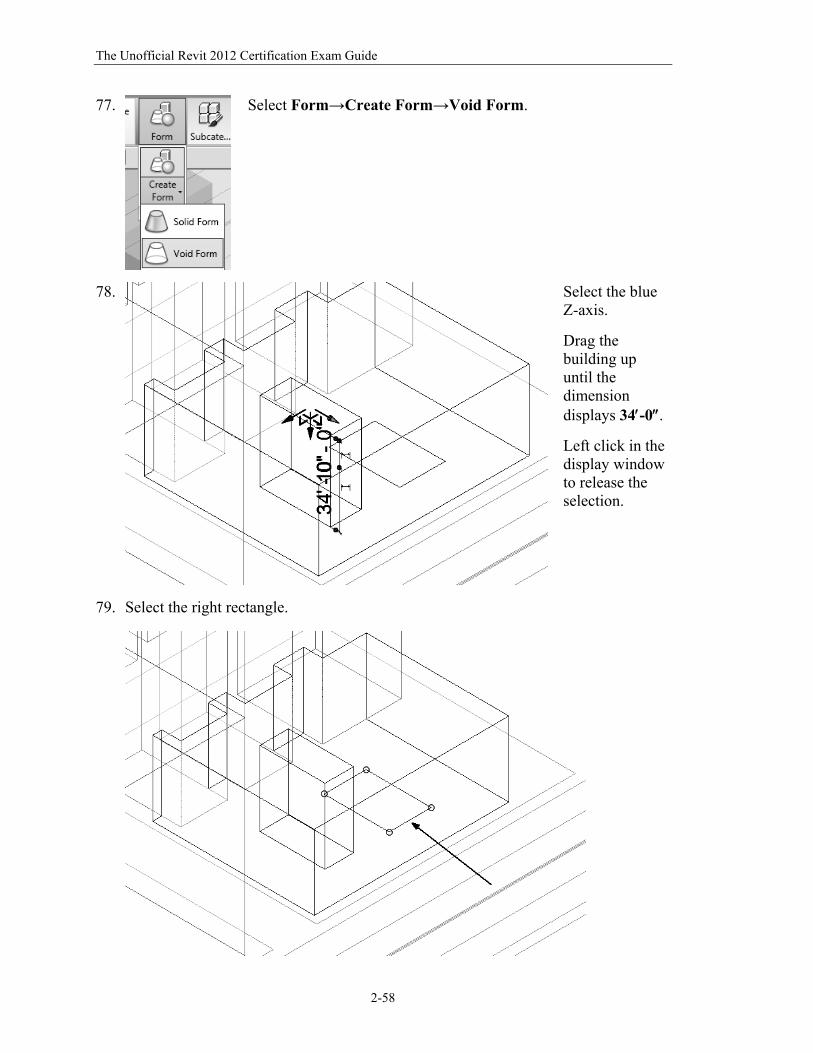
77.
Select Form→Create Form→Void Form.
78.
Select the blue Z-axis.
Drag the building up until the dimension displays 34-0.
Left click in the display window to release the selection.
79. Select the right rectangle.
The Basics of Building a Model
2-59
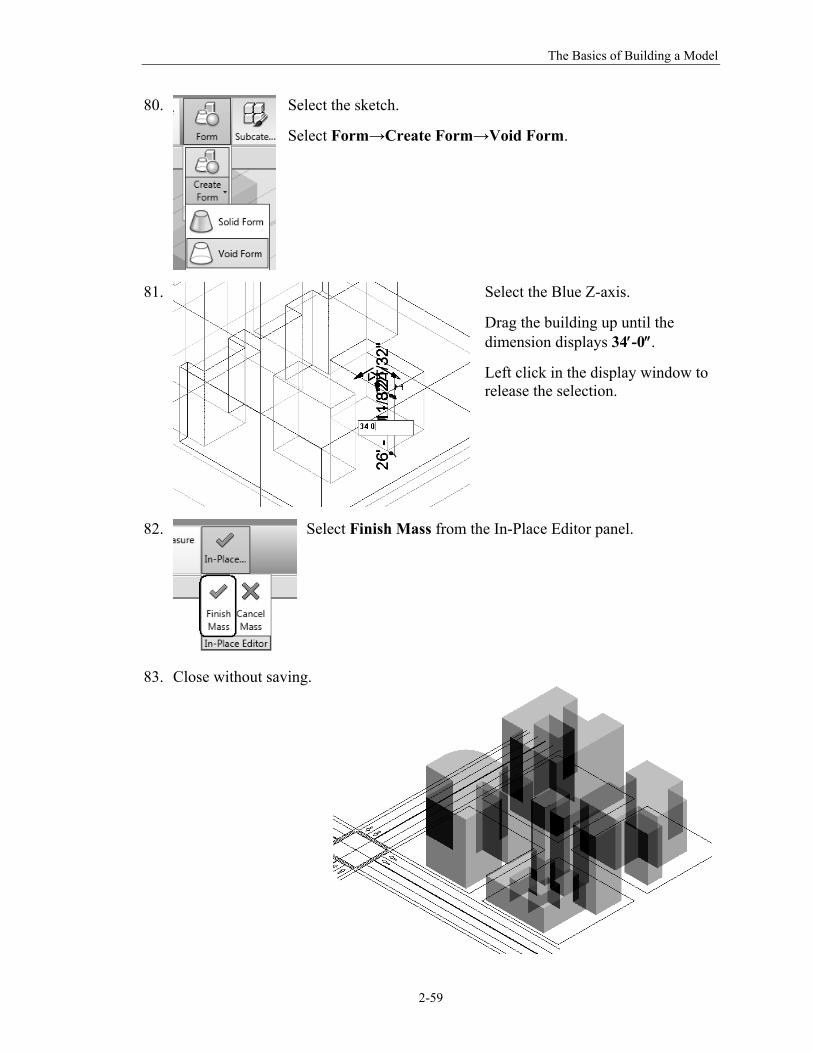
80.
Select the sketch.
Select Form→Create Form→Void Form.
81.
Select the Blue Z-axis.
Drag the building up until the dimension displays 34-0.
Left click in the display window to release the selection.
82.
Select Finish Mass from the In-Place Editor panel.
83. Close without saving.
The Unofficial Revit 2012 Certification Exam Guide
2-60
Command Exercise
Exercise 2-10 – Editing an In-Place Mass
Drawing Name: editing_masses.rvt Estimated Time to Completion: 30 Minutes Scope
Editing in-place masses to develop a conceptual model
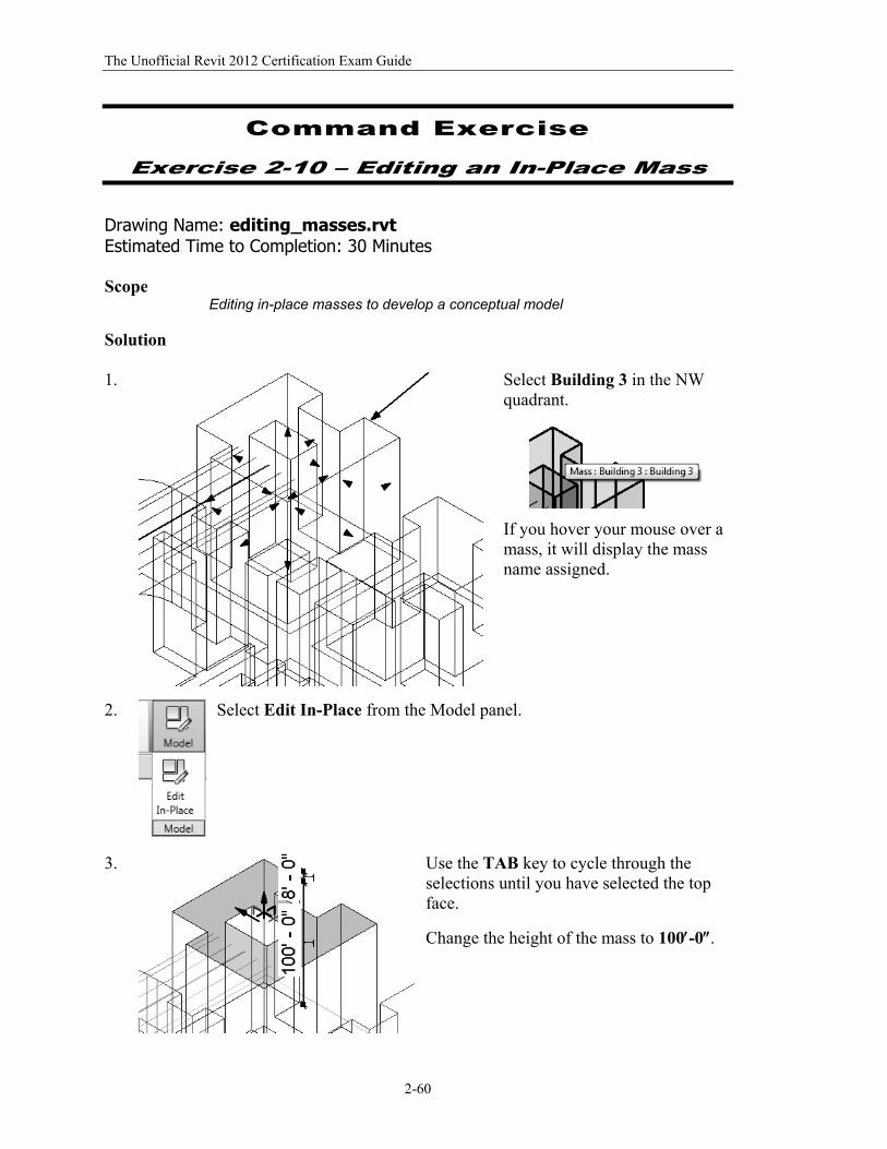
Solution 1.
Select Building 3 in the NW quadrant.
If you hover your mouse over a mass, it will display the mass name assigned.
2.
Select Edit In-Place from the Model panel.
3. Use the TAB key to cycle through the selections until you have selected the top face.
Change the height of the mass to 100-0.
The Basics of Building a Model
2-61
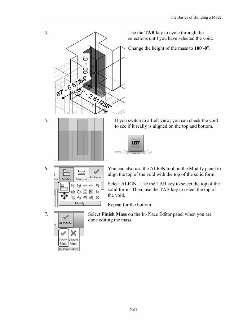
4.
Use the TAB key to cycle through the selections until you have selected the void.
Change the height of the mass to 100-0.
5.
If you switch to a Left view, you can check the void to see if it really is aligned on the top and bottom.
6. You can also use the ALIGN tool on the Modify panel to align the top of the void with the top of the solid form.
Select ALIGN. Use the TAB key to select the top of the solid form. Then, use the TAB key to select the top of the void.
Repeat for the bottom.
7.
Select Finish Mass on the In-Place Editor panel when you are done editing the mass.
The Unofficial Revit 2012 Certification Exam Guide
2-62
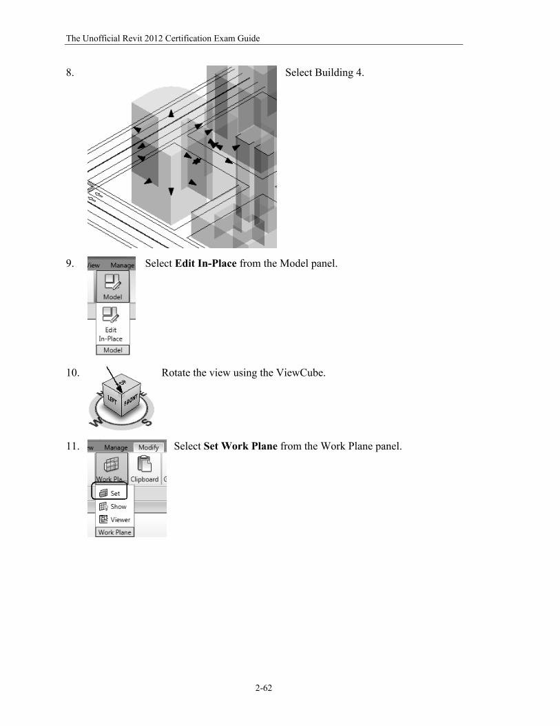
8.
Select Building 4.
9.
Select Edit In-Place from the Model panel.
10.
Rotate the view using the ViewCube.
11.
Select Set Work Plane from the Work Plane panel.
The Basics of Building a Model
2-63
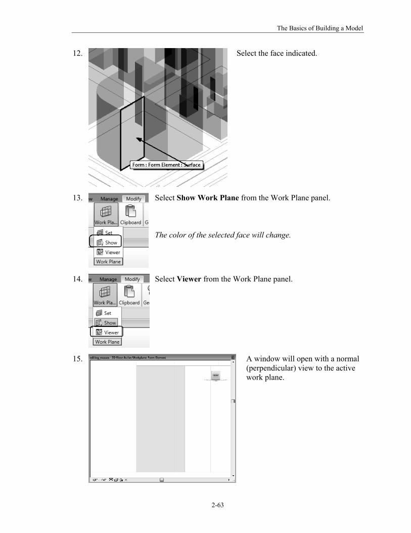
12.
Select the face indicated.
13.
Select Show Work Plane from the Work Plane panel. The color of the selected face will change.
14.
Select Viewer from the Work Plane panel.
15.
A window will open with a normal (perpendicular) view to the active work plane.
The Unofficial Revit 2012 Certification Exam Guide
2-64
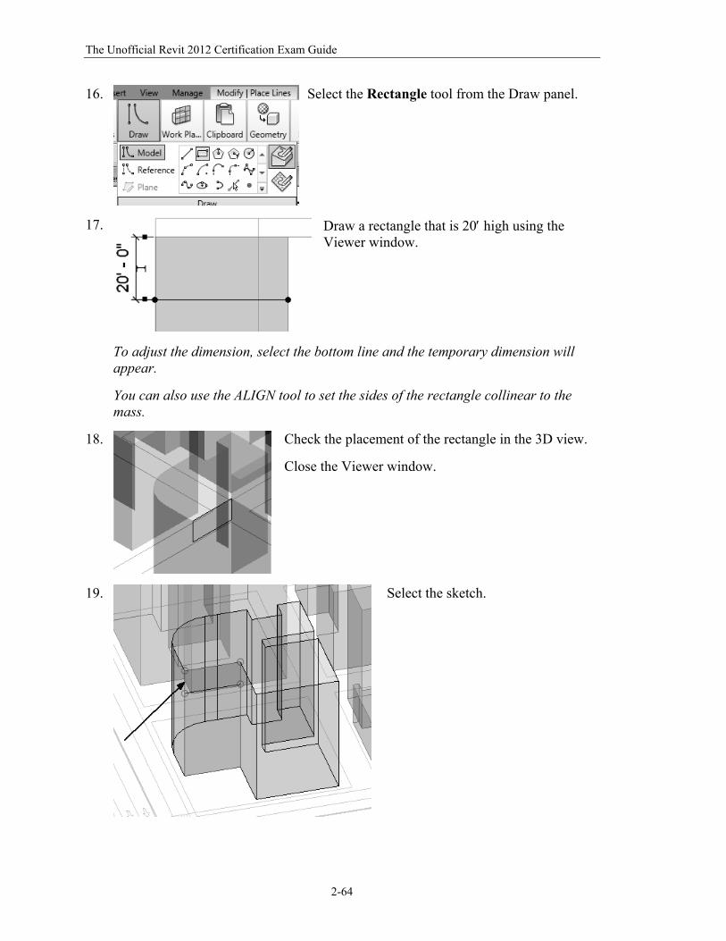
16.
Select the Rectangle tool from the Draw panel.
17.
Draw a rectangle that is 20 high using the Viewer window.
To adjust the dimension, select the bottom line and the temporary dimension will appear. You can also use the ALIGN tool to set the sides of the rectangle collinear to the mass.
18.
Check the placement of the rectangle in the 3D view.
Close the Viewer window.
19.
Select the sketch.
The Basics of Building a Model
2-65
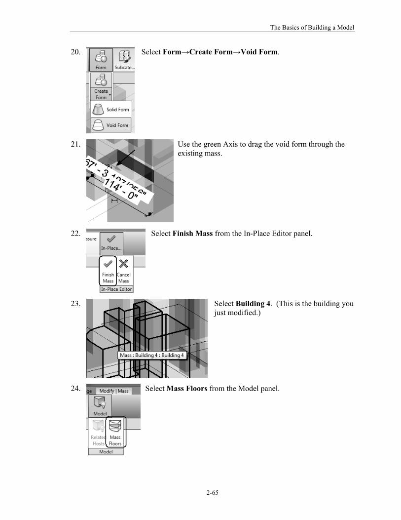
20.
Select Form→Create Form→Void Form.
21.
Use the green Axis to drag the void form through the existing mass.
22.
Select Finish Mass from the In-Place Editor panel.
23.
Select Building 4. (This is the building you just modified.)
24.
Select Mass Floors from the Model panel.
The Unofficial Revit 2012 Certification Exam Guide
2-66
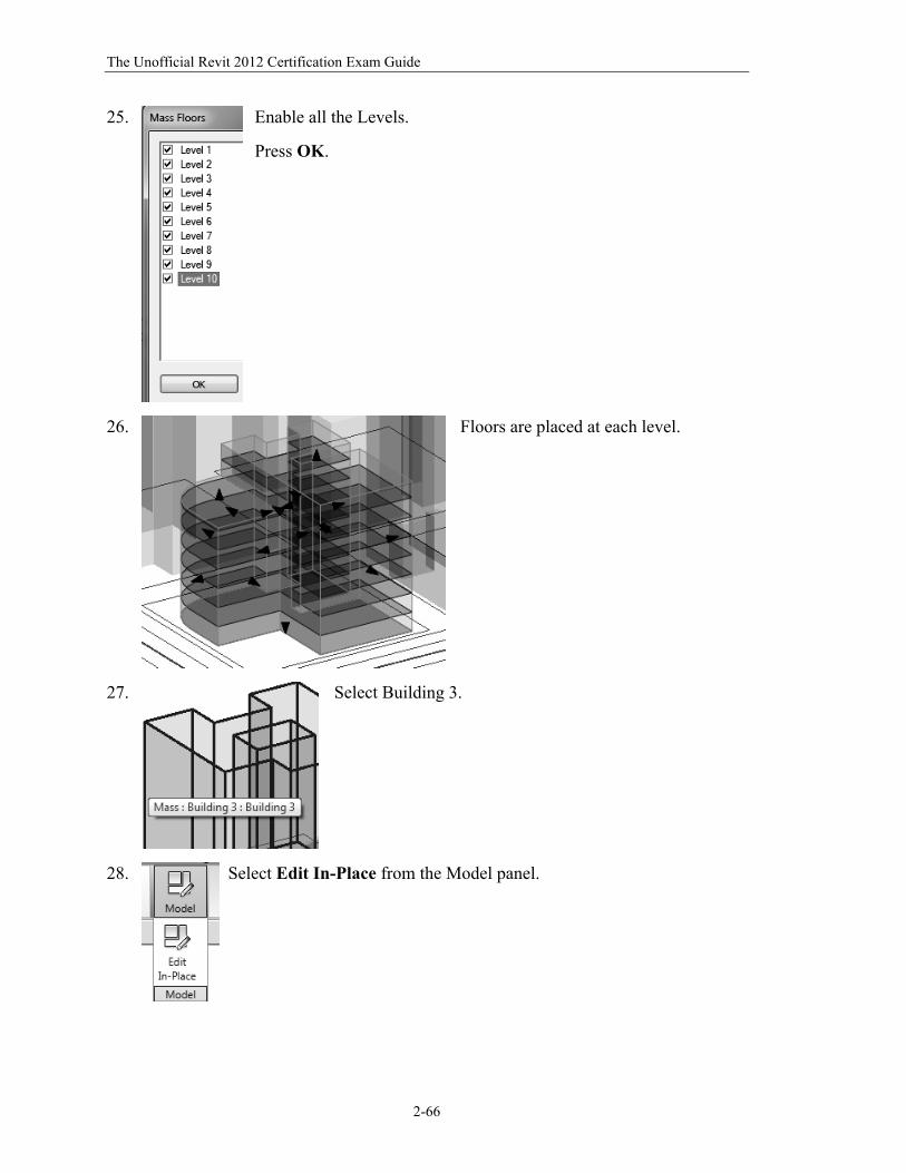
25.
Enable all the Levels.
Press OK.
26.
Floors are placed at each level.
27.
Select Building 3.
28.
Select Edit In-Place from the Model panel.
The Basics of Building a Model
2-67
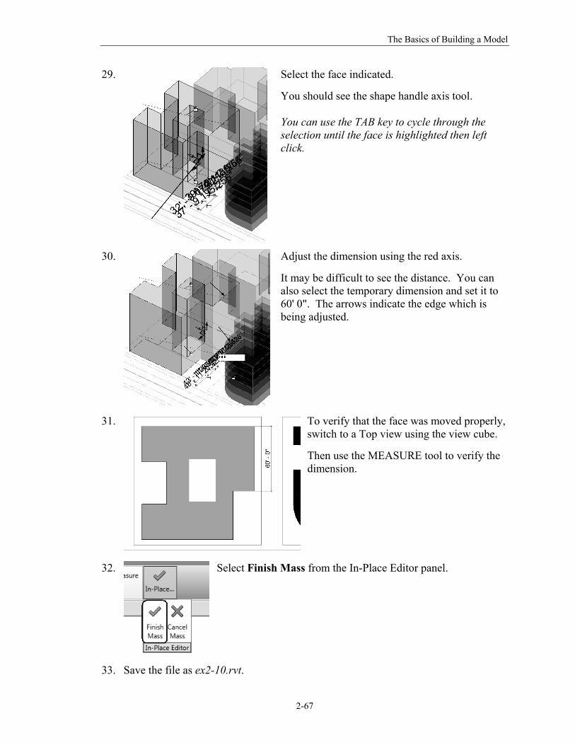
29.
Select the face indicated.
You should see the shape handle axis tool. You can use the TAB key to cycle through the selection until the face is highlighted then left click.
30.
Adjust the dimension using the red axis.
It may be difficult to see the distance. You can also select the temporary dimension and set it to 60' 0". The arrows indicate the edge which is being adjusted.
31.
To verify that the face was moved properly, switch to a Top view using the view cube.
Then use the MEASURE tool to verify the dimension.
32.
Select Finish Mass from the In-Place Editor panel.
33. Save the file as ex2-10.rvt.
The Unofficial Revit 2012 Certification Exam Guide
2-68
Command Exercise
Exercise 2-11 – Mass Properties
Drawing Name: new Estimated Time to Completion: 15 Minutes Scope
Modifying a conceptual mass
Solution 1. Start a new project using the Default template.
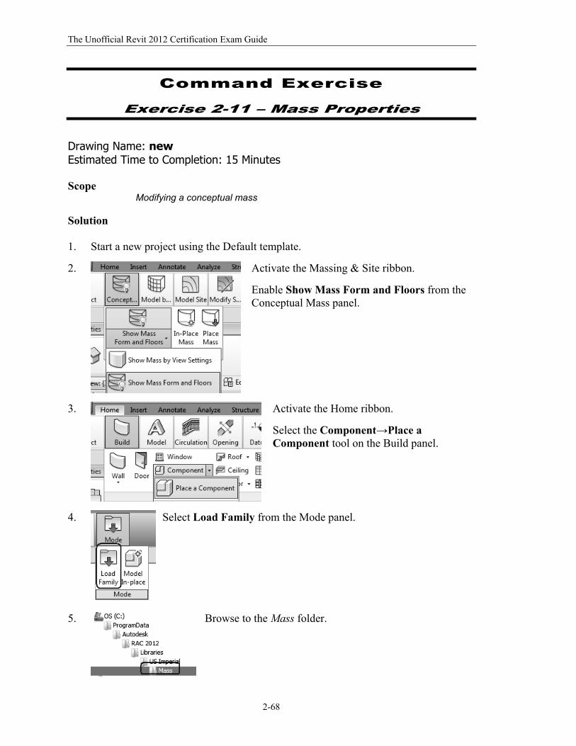
2.
Activate the Massing & Site ribbon.
Enable Show Mass Form and Floors from the Conceptual Mass panel.
3.
Activate the Home ribbon.
Select the Component→Place a Component tool on the Build panel.
4.
Select Load Family from the Mode panel.
5.
Browse to the Mass folder.
The Basics of Building a Model
2-69
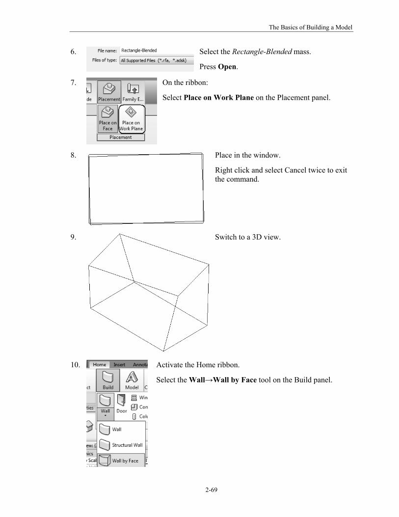
6.
Select the Rectangle-Blended mass.
Press Open.
7.
On the ribbon:
Select Place on Work Plane on the Placement panel.
8.
Place in the window.
Right click and select Cancel twice to exit the command.
9.
Switch to a 3D view.
10.
Activate the Home ribbon.
Select the Wall→Wall by Face tool on the Build panel.
The Unofficial Revit 2012 Certification Exam Guide
2-70
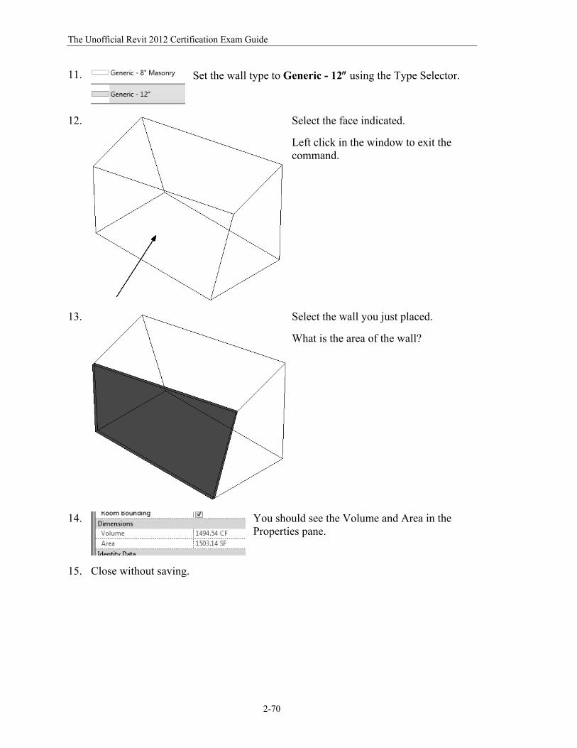
11.
Set the wall type to Generic - 12 using the Type Selector.
12.
Select the face indicated.
Left click in the window to exit the command.
13.
Select the wall you just placed.
What is the area of the wall?
14.
You should see the Volume and Area in the Properties pane.
15. Close without saving.
The Basics of Building a Model
2-71
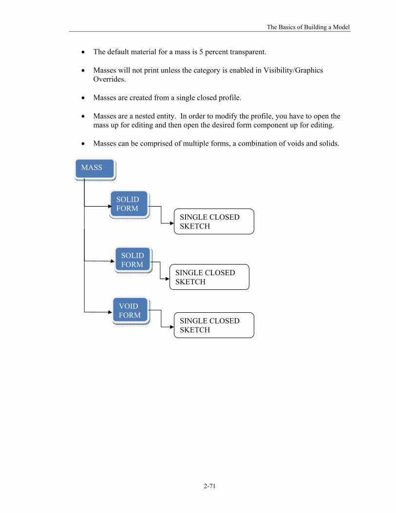
The default material for a mass is 5 percent transparent.
Masses will not print unless the category is enabled in Visibility/Graphics Overrides.
Masses are created from a single closed profile.
Masses are a nested entity. In order to modify the profile, you have to open the mass up for editing and then open the desired form component up for editing.
Masses can be comprised of multiple forms, a combination of voids and solids.
MASS
SOLID FORM
SOLID FORM
VOID FORM
SINGLE CLOSED SKETCH
SINGLE CLOSED SKETCH
SINGLE CLOSED SKETCH
The Unofficial Revit 2012 Certification Exam Guide
2-72
Practice Associate Exam
1. Which of the following can NOT be defined prior to placing a wall?
A. Unconnected Height B. Base Constraint C. Location Line D. Profile E. Top Offset
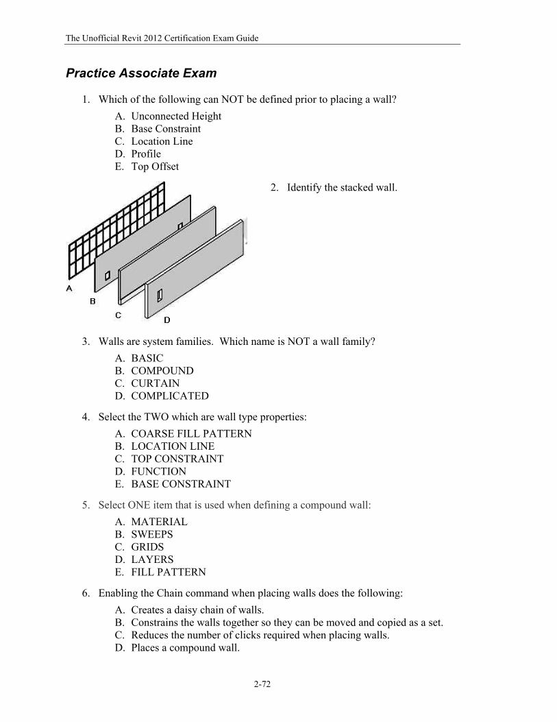
2. Identify the stacked wall.
3. Walls are system families. Which name is NOT a wall family?
A. BASIC B. COMPOUND C. CURTAIN D. COMPLICATED
4. Select the TWO which are wall type properties:
A. COARSE FILL PATTERN B. LOCATION LINE C. TOP CONSTRAINT D. FUNCTION E. BASE CONSTRAINT
5. Select ONE item that is used when defining a compound wall:
A. MATERIAL B. SWEEPS C. GRIDS D. LAYERS E. FILL PATTERN
6. Enabling the Chain command when placing walls does the following:
A. Creates a daisy chain of walls. B. Constrains the walls together so they can be moved and copied as a set. C. Reduces the number of clicks required when placing walls. D. Places a compound wall.
The Basics of Building a Model
2-73
7. Use this key to cycle through selections:
A. TAB B. CTL C. SHIFT D. ALT
8. When working with a mass, you can use levels to define mass __________
A. Roofs B. Floors C. Ceilings D. Walls
9. To create a mass that is unique in a project, use the _________ Mass tool.
A. In-Place B. Component C. System D. By Face
10. Selecting a work plane:
A. Automatically changes the relative coordinate system B. Changes the project location C. Changes the level D. Determines the depth of an extrusion
11. The construction of a stacked wall is defined by different wall _______.
A. Types B. Layers C. Regions D. Instances
12. To change the structure of a basic wall you must modify it's:
A. Type Parameters B. Instance Parameters C. Structural Usage D. Function
13. Select THREE element types than can be created using mass faces:
A. Doors B. Walls C. Levels D. Floors E. Roofs
The Unofficial Revit 2012 Certification Exam Guide
2-74
14. Select TWO methods used to create a conceptual design using mass families;
A. Go to the Applications Menu and select New→Conceptual Mass. B. Go to the Massing & Site ribbon and select Place Mass. C. Go to the Applications Menu and select New→Family D. Go to the Massing & Site ribbon and select In-Place Mass E. Go to the Applications Menu and select New→Project
15. In order to place a wall or floor on a mass face, the face must be:
A. Horizontal B. Vertical C. Either Horizontal or Vertical D. Curved or spherical E. None of the above
16. To divide a floor or wall into parts, you can use the following (select all that
apply):
A. Lines B. Levels C. Grids D. Circles E. Arcs
17. To display parts in a view:
A. Go to the Massing & Site ribbon and select Show Mass. B. On the View Properties pane: set Parts Visibility to Show Parts C. Go to the Visibility/Graphics dialog and enable Parts. D. Go to Temporary Hide/Isolate and Reset
18. To assign a different material to a part, select the part and:
A. On the Properties pane: Enable Material by Original B. Right click and select Assign Material C. On the Modify ribbon, select Paint from the Geometry Panel. D. On the Properties pane: Uncheck Material by Original, then assign a
material in the material field.
Answers:
1) D; 2) C; 3) D; 4) A & D; 5) D; 6) C; 7) A; 8) B; 9) A; 10) A; 11) A; 12) A; 13) B, D, & E; 14) A & D; 15) E; 16) A, B, C, & D; 17) B; 18) D