Embed Size (px)
Citation preview
SUPPLEMENTAL SITE INVESTIGATION
WORK PLAN
SOIL GAS SAMPLING AND ANALYSIS
FORMER TIDEWATER FACILITY
PROVIDENCE, RHODE ISLAND
PREPARED FOR:
RIDEM
Providence, Rhode Island
PREPARED BY:
GZA GeoEnvironmental, Inc.
Providence, Rhode Island
May 2013
File No. 43654.00
GZA Engineers and
GeoEnvironmental, Inc. Scientists
530 Broadway
Providence
Rhode Island
02909
401-421-4140
FAX 401-751-8613
http://www.gza.com
May 2, 2013
File No. 05.0043654.00
Via E-Mail and U.S. Mail
Mr. Joseph Martella
Rhode Island Department of Environmental Management (RIDEM)
Office of Waste Management
235 Promenade Street
Providence, Rhode Island 02908
Re: Supplemental Site Investigation Work Plan
Soil Gas Sampling and Analysis
Former Tidewater Facility
Pawtucket, Rhode Island
Dear Mr. Martella:
On behalf of the Narragansett Electric Company d/b/a National Grid (National Grid), GZA
GeoEnvironmental, Inc. (GZA) is pleased to present to the Rhode Island Department of
Environmental Management (RIDEM) the attached Supplemental Site Investigation Work Plan
(SSIWP) for your review. Per your request, this SSIWP describes a proposed program designed
to evaluate soil gas quality at the Tidewater Site.
Please feel free to contact either of the undersigned or Michele Leone at 781-907-3651 should
you have any questions.
Very truly yours,
GZA GEOENVIRONMENTAL, INC.
Margaret S. Kilpatrick, P.E.
Senior Project Manager
James J. Clark, P.E.
Principal
MSK/JJC:tja
Attachment: SSIWP – Soil Gas Sampling and Analysis
cc: Elizabeth Stone, RIDEM
Michele Leone, National Grid
J:\ENV\43654.msk\WORK\VI Data\Work Plan\43654 00 Final Soil Gas WP Cover Letter.docx
TABLE OF CONTENTS
Page
1.00 INTRODUCTION 1
2.00 EXISTING SOIL GAS QUALITY DATA 2
3.00 PROPOSED SCOPE OF WORK 2
TABLE
TABLE NO. 1 SUMMARY OF SOIL GAS PROBE INSTALLATIONS
FIGURES
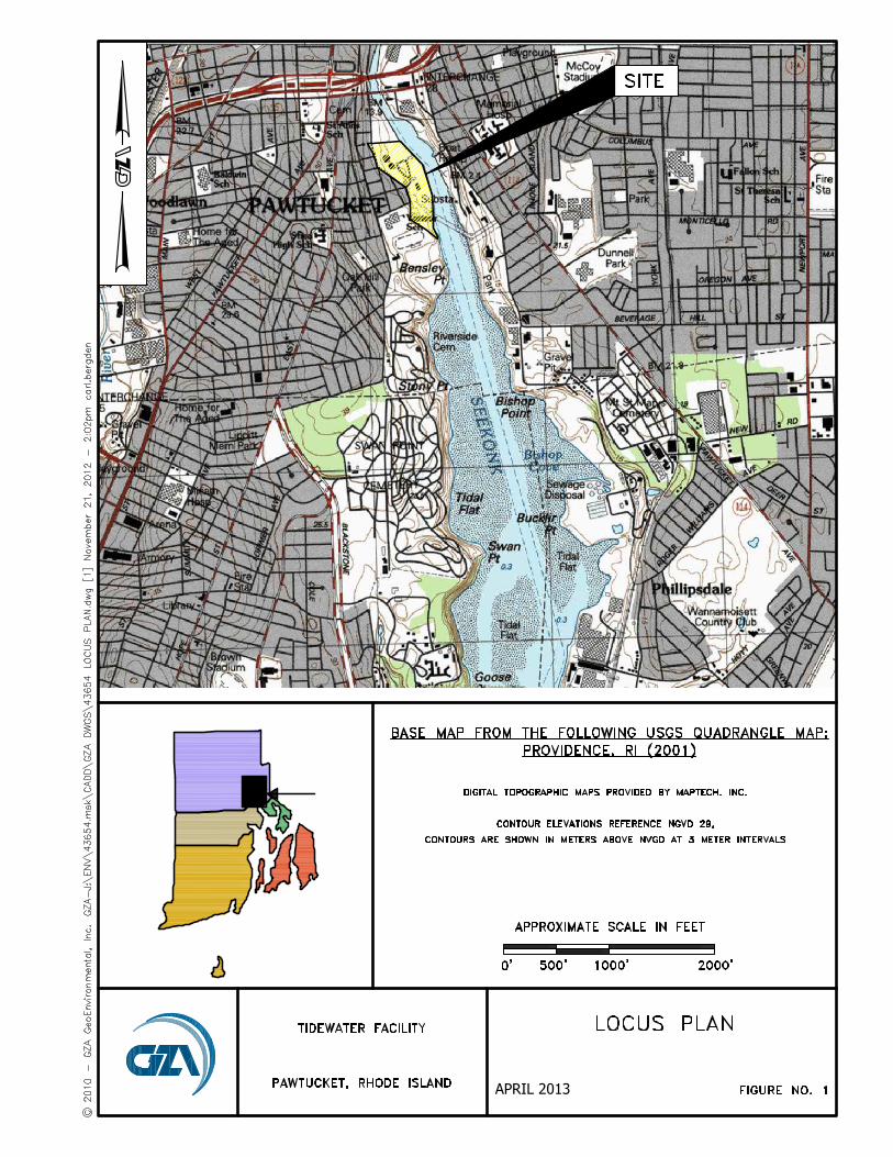
FIGURE NO. 1 SITE LOCUS PLAN
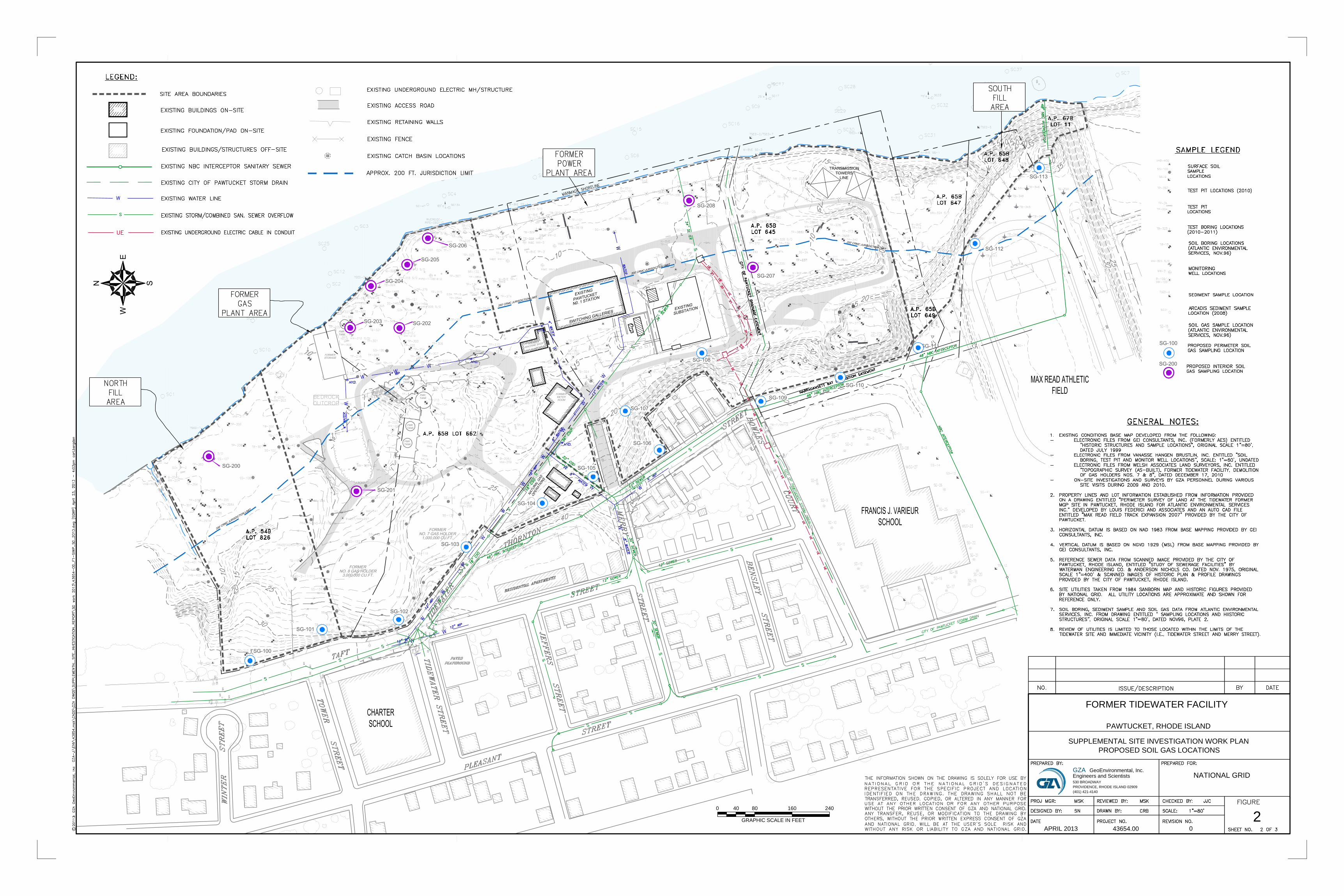
FIGURE NO. 2 PROPOSED SOIL GAS LOCATIONS
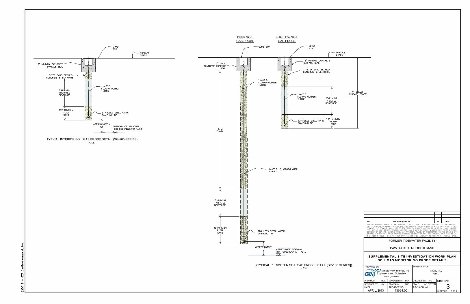
FIGURE NO. 3 SOIL GAS PROBE – TYPICAL DETAIL
APPENDICES
APPENDIX A 1996 AES SOIL GAS SAMPLING RESULTS

May 2, 2013 – File No. 43654.00 –Page 1
1.00 INTRODUCTION
On behalf of The Narragansett Electric Company, d/b/a National Grid (National Grid),
GZA GeoEnvironmental Inc. (GZA) has prepared this Supplemental Site Investigation
Work Plan (SSIWP) describing proposed soil gas sampling and analyses to be performed at
the former Tidewater facility located at the terminus of Tidewater and Merry Streets in
Pawtucket, Rhode Island (herein referred to as the Site). Figure 1 presents a Site Locus
Plan.
The Site is located on the west side of the Seekonk River and is bound to the west by
residential properties, to the south and southwest by the Francis J. Varieur School and Max
Read Athletic Field, and to the north by undeveloped property owned by the City of
Pawtucket. It encompasses approximately 23 acres and was the location of the former
Tidewater Manufactured Gas Plant (MGP) and the Pawtucket No. 1 Power Station. The
Site is currently largely vacant with the exception of an active natural gas regulating
station, an active switching station and electric substation, and two transmission towers
owned and operated by National Grid.
The proposed soil gas investigation program described herein will serve to supplement the
Site Investigation Report (SIR) which was completed with the submission of the Site
Investigation Data Report (SIDR) in January 2011 and the Remedial Alternative
Evaluation in July 2011. The SIDR and Remedial Alternative Evaluation serve to fulfill
the requirements of the Rhode Island Department of Environmental Management
(RIDEM) Rules and Regulations for the Investigation and Remediation of Hazardous
Material Releases (Remediation Regulations–DEM-DSR-01-93), Sections 7.03, 7.04, and
7.05 for a SIR.
For details regarding the existing and historic Site conditions, including Site plans,
previous Site investigations, hydrogeologic setting and observed impacts, please refer to
reports previously submitted to the Rhode Island Department of Environmental
Management (RIDEM).
Per RIDEM’s request, this SSIWP presents a proposed soil gas sampling and analysis
program designed to evaluate the quality of soil gas at the Tidewater Site. As described
further herein, this program includes the collection and analysis of soil gas both in interior
portions of the Site and along the western property boundary. Please note, based on our
evaluation of the nature and extent of volatile constituents detected on-Site, the Site
hydrogeologic setting, and current use (no occupied structures), a specific evaluation of
soil gas quality was not warranted and therefore not included as part of the investigations
May 2, 2013 – File No. 43654.00 –Page 2
performed to support development of the SIR for the Tidewater Site. In addition, the
potential migration of impacted soil gas was not identified as an exposure pathway for the
Site.
2.00 EXISTING SOIL GAS QUALITY DATA
As described previously, Site soil gas sampling and analysis was not performed as part of
the SIR based on the observed nature and extent of impacts, the hydrogeologic setting, and
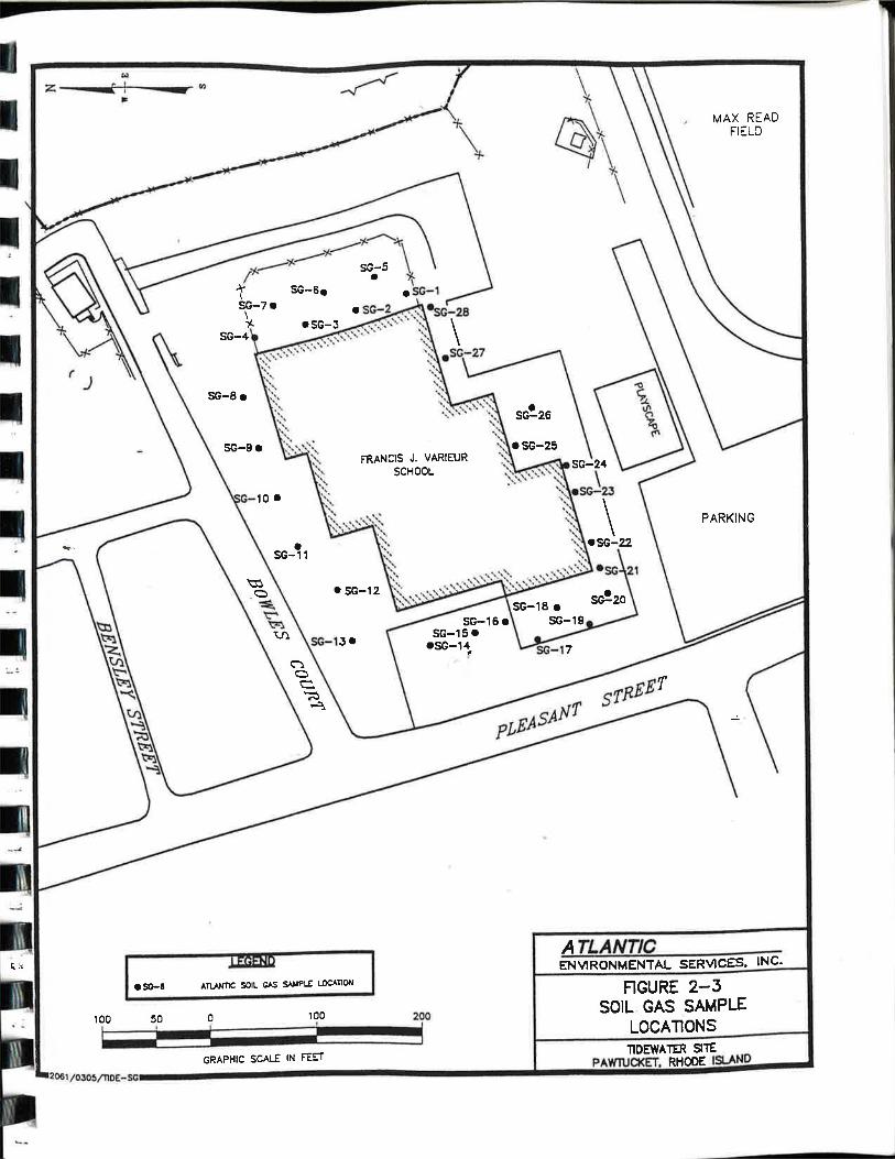
Site use. As documented in the SIR, a soil-gas survey was conducted as part of the
investigation of the Francis J. Varieur School facility by Atlantic Environmental Solutions,
Inc. (AES) in 1996. The survey was conducted adjacent to the school building and
consisted of 28 sampling points which are shown on the attached Figure 2 and in Appendix
A, as soil gas sampling locations SG-1 to SG-28.
Soil-gas samples were collected at a depth of approximately 3 to 4 feet below ground
surface via the advancement of soil-gas sampling points. Soil-gas samples were analyzed
in the field for benzene, toluene, ethylbenzene and xylenes (BTEX) using a Photovac 10S
Plus portable gas chromatograph. Standards and blank samples (approximately 10 percent
of the total samples) were also analyzed for quality assurance/quality control (QA/QC)
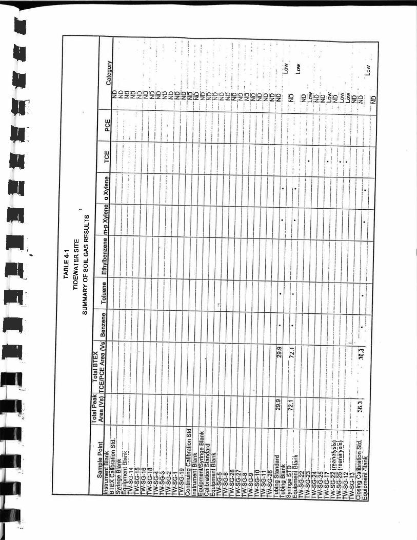
purposes during the survey. The analytical results included as Appendix A
A present results of this survey. There were no BTEX compounds detected. Two samples,
TW-SG-22 and TW-SG-25, indicated possible low levels of trichloroethane (TCE).
Subsequent re-sampling and re-analysis confirmed the presence of this non-target analyte.
TCE is not a constituent associated with former MGP or petroleum storage facilities or
with current National Grid operations.
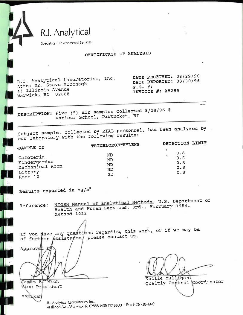
Following an initial review of the soil gas survey data, it was determined that indoor air
quality monitoring for TCE would be implemented at the Francis J. Varieur School. The
air monitoring program consisted of the collection of five samples inside the school on
August 28, 1996. Sample locations included the cafeteria, the kindergarten classroom, the
mechanical room, the library, and Room 13. All five samples were non-detect for TCE at a
detection limit of 0.8 mg/m3. These analytical results are also included in Appendix A.
May 2, 2013 – File No. 43654.00 –Page 3
3.00 PROPOSED SCOPE OF WORK
This section presents the proposed scope of investigations designed to evaluate the quality
of soil gas within certain interior portions and proximate to the western property line of the
Tidewater Site. A total of 23 sampling locations are proposed (SG-100 to SG-113 and SG-
200 to SG-208, see Figure 2). The SG-100 series is located along the western Site
perimeter and the SG-200 series is located within interior portions of the Site. The
proposed interior sampling points are located proximate to areas where elevated levels of
volatile constituents were detected in soil and/or groundwater during previous explorations
and are designed to evaluate worse case soil gas conditions. The SG-100 series locations
are designed to assess the quality of soil gas proximate to the Site property boundary. As
described further below and in the attached Table 1, certain soil gas sampling locations
were specifically selected to evaluate the quality of soil gas proximate to existing
subsurface utility lines. Proposed soil gas sampling locations are depicted on the attached
Figure 2.
Fieldwork associated with this exploration program will be completed consistent with a
Health and Safety Plan (HASP) prepared for the project.
The following sections present the proposed scope of these soil gas investigations.
CRMC Permitting
A portion of the proposed investigation locations are within 200-feet of the coastal
feature, and as such, are subject to the jurisdiction of the Coastal Resource Management
Council (CRMC). GZA will prepare a CRMC permit application package associated with
completion of the proposed exploration program. Due to the relatively non-invasive nature
of the work, we have assumed that completion of the proposed subsurface exploration
program will fall under a “Finding of No Significant Impact” (FONSI).
Coordination with the City of Pawtucket
As shown on Figure 2, two sampling probes (SG-112 and SG-113) are located on
City of Pawtucket property (A.P. 65B Lot 648) directly proximate to the Max Read Field.
This work will require access coordination with the City of Pawtucket.
Soil Gas Probe Installations
Twenty three (23) soil gas probes will be installed at the locations shown on Figure
2. The location rationale and proposed depth of each probe are summarized in Table 1.
May 2, 2013 – File No. 43654.00 –Page 4
Fourteen (14) soil gas probes (SG-100 through SG-113) will be installed proximate to the
western Site boundary and nine (9) probes (SG-200 through SG-208) will be installed
within interior Site areas. SG-200 is located in the former North Fill Area proximate to
monitoring well MW-310 where benzene and naphthalene have been detected at
concentrations in excess of the GB Groundwater Objectives. Similarly, SG-201 through
SG-206, which are located in the Former Gas Plant Area, are proximate to groundwater
monitoring wells where benzene and naphthalene have been detected at concentrations in
excess of the GB Groundwater Objectives. Five (5) probes (SG-103, SG-109, SG-113,
SG-207, and SG-208) are specifically located proximate to utility lines which extend
through the Site (the Narragansett Bay Commission (NBC) Combined Sewer Overflow,
City of Pawtucket Storm Drain, the NBC Sanitary Sewer force main and the National Grid
Underground Electric service). In addition, three (3) probes (SG-102, SG-103and SG-105)
are located proximate to the Pawtucket Water Supply Board (PWSB) 12” city water main.
Anticipated soil gas sampling depths are summarized in Table 1. The general
approach for the interior sampling locations where the water table is encountered
approximately 4 to 7 feet below grade will be to collect soil gas from approximately one
foot above the natural water table. In addition, at location SG-203, soil gas samples will be
collected at multiple depths within the vadose zone in an effort to assess volatile
compound degradation rates. At this locations it is anticipated that 3 soil gas samples, each
separated by approximately one foot vertically will be collected and analyzed. At the Site
boundary locations where the depth to groundwater is anticipated to range from
approximately 15 to 25 feet below grade, soil gas samples will be collected at two depths,
approximately one foot above the water table and approximately 5 feet below grade.
Prior to installation, an area reconnaissance will be performed to confirm rig access
and assess underground utility locations. In addition, DigSafe will be contacted consistent
with Rhode Island state law. Certain locations and terminus depths may require field
adjustments based on access restrictions, the presence of utilities, and/or subsurface
obstructions or drilling refusal.
The soil gas probes will be installed using direct push technology (Geoprobe® rig
and /or hand operated vibratory drilling equipment). As described further herein, this
installation approach will significantly minimize subsurface disturbance. At each location,
a specially designed, stainless steel vapor sampling tip will be advanced to the desired
depth (AMS Dedicated Tip, Geoprobe® Implant, or equal). At certain locations it may be
necessary to advance a pilot hole to facilitate installation of the soil gas sampling tip and
tubing. Fluoropolymer tubing (1/4” O.D.) will be connected to each tip and extended to
the ground surface to allow for the collection of a soil gas sample. Filter sand will be
placed in the annular space around the vapor sampling tip to one foot above the tip. The
May 2, 2013 – File No. 43654.00 –Page 5
sand and tip will then be sealed with a 2-foot thick layer of hydrated bentonite to prevent
short circuiting. The remainder of the borehole will be backfilled with sand. A small
diameter road box will be placed over each probe to protect the sample tubing and sealed at
the surface with a 1-foot thick plug of Portland cement. Alternatively, certain probes may
be finished with an approximately 2 feet tall steel standpipe. A typical detail of the
proposed soil vapor collection probe for both the interior and perimeter locations is
provided on the attached Figure 3.
As indicated above, the use of vibratory direct push techniques to install the probes
will significantly limit subsurface disturbance. No significant soil cuttings or wash waters
are expected.
Soil Vapor Sampling and Analysis Procedures
After installation, each soil gas probe will be allowed to equilibrate for at least 2 to
3 hours prior to sample collection. At least 3 times the volume of the tubing will be
extracted from the probe using an air pump prior to sample collection. Well purging and
sampling will be performed at a flow rate of approximately 200 milliliters per minute to
limit the potential for short-circuiting. During purging, soil gas will be collected into
Tedlar bags for Total Volatile Organic Compounds (TVOCs) and oxygen screening using
a MiniRAE 5-Gas meter equipped with a 10.6 eV lamp for TVOCs screening. Soil gas
samples will be collected from each probe using 2.7 L Summa canisters and submitted to
the laboratory for low level VOC analysis via EPA Method TO-15, plus naphthalene.
The soil gas samples will be transported under chain-of-custody protocol to a
qualified laboratory.
Meteorological conditions (barometric pressure, temperature and rainfall) will be
recorded and documented during the sampling event.
To assess potential laboratory induced contamination, the qualified laboratory will
prepare and analyze three Trip Blanks for the sampling round. Trip Blanks follow the
sample containers, and subsequently the collected samples, through the monitoring process
and can be used to assess the presence of non–Site related contaminants that may be
introduced from the environment during the sampling and transportation process.
Two to three field duplicate samples will also be collected and analyzed to evaluate
the reproducibility of the sampling methods.
May 2, 2013 – File No. 43654.00 –Page 6
Environmental Monitoring and Health and Safety Procedures
As described above, the vibratory direct push installation technique significantly
limits subsurface disturbance during probe installation. Unlike other drilling techniques,
direct push does not produce excess soils because the probe is pushed into the ground with
no augering. Given this limited subsurface disturbance, the likelihood of dust and VOC
generation above background levels is extremely limited; therefore, adherence to all the
provisions outlined in the April 2011 Air Quality Monitoring Program (AQMP) is not
warranted for this work. Specifically, real time monitoring for benzene and the second tier
time integrated air quality sampling and analysis described in the AQMP are not
warranted. Real time air quality monitoring will be performed using hand held instruments
generally consistent with the first tier monitoring described in the AQMP and our Site
Specific Health and Safety Plan (HASP). This monitoring will include TVOCs and dust in
both the worker breathing zone and work zone perimeter. TVOCs will be monitored using
a hand held photoionization detector equipped with a 10.6 eV lamp. Particulate dust will
be monitored using a DustTrak. The work zone perimeter action limit for TVOCs and dust
will be set at 0.1 ppmv and 150 µg/m3, respectively, which are consistent with the Site
perimeter action limits established in the AQMP. The air monitoring data will be posted to
the bulletin boards at the end Tidewater Street and Bowles Court.
Data Summary Report
A report will be prepared and submitted to RIDEM approximately three weeks
following receipt of the laboratory data. This report will include text describing the work
completed, a figure showing the soil gas probe locations, a tabular summary of the soil gas
analytical data, soil gas probe installation logs, and laboratory reports.
J:\ENV\43654.msk\WORK\VI Data\Work Plan\43654 00 final SSIWP Text 5-2-13 .docx

TABLE
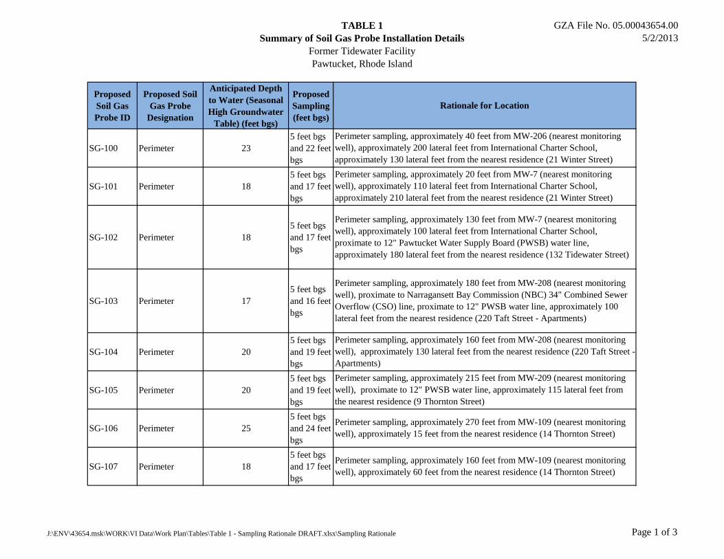
TABLE 1
Summary of Soil Gas Probe Installation Details
Former Tidewater Facility
Pawtucket, Rhode Island
GZA File No. 05.00043654.00
5/2/2013
Proposed
Soil Gas
Probe ID
Proposed Soil
Gas Probe
Designation
Anticipated Depth
to Water (Seasonal
High Groundwater
Table) (feet bgs)
Proposed
Sampling
(feet bgs)
SG-100 Perimeter 23
5 feet bgs
and 22 feet
bgs
SG-101 Perimeter 18
5 feet bgs
and 17 feet
bgs
SG-102 Perimeter 18
5 feet bgs
and 17 feet
bgs
SG-103 Perimeter 17
5 feet bgs
and 16 feet
bgs
SG-104 Perimeter 20
5 feet bgs
and 19 feet
bgs
SG-105 Perimeter 20
5 feet bgs
and 19 feet
bgs
SG-106 Perimeter 25
5 feet bgs
and 24 feet
bgs
SG-107 Perimeter 18
5 feet bgs
and 17 feet
bgs
Rationale for Location
Perimeter sampling, approximately 40 feet from MW-206 (nearest monitoring
well), approximately 200 lateral feet from International Charter School,
approximately 130 lateral feet from the nearest residence (21 Winter Street)
Perimeter sampling, approximately 20 feet from MW-7 (nearest monitoring
well), approximately 110 lateral feet from International Charter School,
approximately 210 lateral feet from the nearest residence (21 Winter Street)
Perimeter sampling, approximately 130 feet from MW-7 (nearest monitoring
well), approximately 100 lateral feet from International Charter School,
proximate to 12" Pawtucket Water Supply Board (PWSB) water line,
approximately 180 lateral feet from the nearest residence (132 Tidewater Street)
Perimeter sampling, approximately 180 feet from MW-208 (nearest monitoring
well), proximate to Narragansett Bay Commission (NBC) 34" Combined Sewer
Overflow (CSO) line, proximate to 12" PWSB water line, approximately 100
lateral feet from the nearest residence (220 Taft Street - Apartments)
Perimeter sampling, approximately 160 feet from MW-208 (nearest monitoring
well), approximately 130 lateral feet from the nearest residence (220 Taft Street -
Apartments)
Perimeter sampling, approximately 215 feet from MW-209 (nearest monitoring
well), proximate to 12" PWSB water line, approximately 115 lateral feet from
the nearest residence (9 Thornton Street)
Perimeter sampling, approximately 270 feet from MW-109 (nearest monitoring
well), approximately 15 feet from the nearest residence (14 Thornton Street)
Perimeter sampling, approximately 160 feet from MW-109 (nearest monitoring
well), approximately 60 feet from the nearest residence (14 Thornton Street)
J:\ENV\43654.msk\WORK\VI Data\Work Plan\Tables\Table 1 - Sampling Rationale DRAFT.xlsx\Sampling Rationale Page 1 of 3
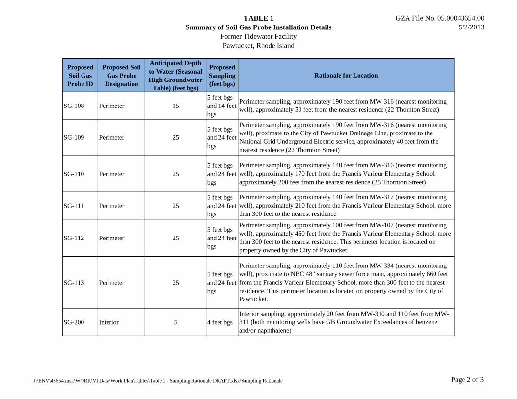
TABLE 1
Summary of Soil Gas Probe Installation Details
Former Tidewater Facility
Pawtucket, Rhode Island
GZA File No. 05.00043654.00
5/2/2013
Proposed
Soil Gas
Probe ID
Proposed Soil
Gas Probe
Designation
Anticipated Depth
to Water (Seasonal
High Groundwater
Table) (feet bgs)
Proposed
Sampling
(feet bgs)
Rationale for Location
SG-108 Perimeter 15
5 feet bgs
and 14 feet
bgs
SG-109 Perimeter 25
5 feet bgs
and 24 feet
bgs
SG-110 Perimeter 25
5 feet bgs
and 24 feet
bgs
SG-111 Perimeter 25
5 feet bgs
and 24 feet
bgs
SG-112 Perimeter 25
5 feet bgs
and 24 feet
bgs
SG-113 Perimeter 25
5 feet bgs
and 24 feet
bgs
SG-200 Interior 5 4 feet bgs
Perimeter sampling, approximately 140 feet from MW-316 (nearest monitoring
well), approximately 170 feet from the Francis Varieur Elementary School,
approximately 200 feet from the nearest residence (25 Thornton Street)
Perimeter sampling, approximately 190 feet from MW-316 (nearest monitoring
well), approximately 50 feet from the nearest residence (22 Thornton Street)
Perimeter sampling, approximately 190 feet from MW-316 (nearest monitoring
well), proximate to the City of Pawtucket Drainage Line, proximate to the
National Grid Underground Electric service, approximately 40 feet from the
nearest residence (22 Thornton Street)
Perimeter sampling, approximately 140 feet from MW-317 (nearest monitoring
well), approximately 210 feet from the Francis Varieur Elementary School, more
than 300 feet to the nearest residence
Perimeter sampling, approximately 100 feet from MW-107 (nearest monitoring
well), approximately 460 feet from the Francis Varieur Elementary School, more
than 300 feet to the nearest residence. This perimeter location is located on
property owned by the City of Pawtucket.
Perimeter sampling, approximately 110 feet from MW-334 (nearest monitoring
well), proximate to NBC 48" sanitary sewer force main, approximately 660 feet
from the Francis Varieur Elementary School, more than 300 feet to the nearest
residence. This perimeter location is located on property owned by the City of
Pawtucket.
Interior sampling, approximately 20 feet from MW-310 and 110 feet from MW-
311 (both monitoring wells have GB Groundwater Exceedances of benzene
and/or naphthalene)
J:\ENV\43654.msk\WORK\VI Data\Work Plan\Tables\Table 1 - Sampling Rationale DRAFT.xlsx\Sampling Rationale Page 2 of 3
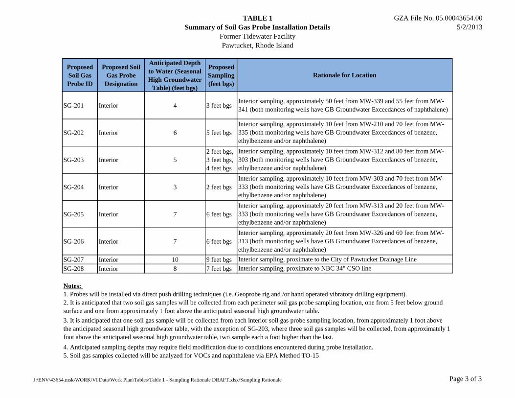
TABLE 1
Summary of Soil Gas Probe Installation Details
Former Tidewater Facility
Pawtucket, Rhode Island
GZA File No. 05.00043654.00
5/2/2013
Proposed
Soil Gas
Probe ID
Proposed Soil
Gas Probe
Designation
Anticipated Depth
to Water (Seasonal
High Groundwater
Table) (feet bgs)
Proposed
Sampling
(feet bgs)
Rationale for Location
SG-201 Interior 4 3 feet bgs
SG-202 Interior 6 5 feet bgs
SG-203 Interior 5
2 feet bgs,
3 feet bgs,
4 feet bgs
SG-204 Interior 3 2 feet bgs
SG-205 Interior 7 6 feet bgs
SG-206 Interior 7 6 feet bgs
SG-207 Interior 10 9 feet bgs
SG-208 Interior 8 7 feet bgs
Notes:
1. Probes will be installed via direct push drilling techniques (i.e. Geoprobe rig and /or hand operated vibratory drilling equipment).
4. Anticipated sampling depths may require field modification due to conditions encountered during probe installation.
5. Soil gas samples collected will be analyzed for VOCs and naphthalene via EPA Method TO-15
3. It is anticipated that one soil gas sample will be collected from each interior soil gas probe sampling location, from approximately 1 foot above
the anticipated seasonal high groundwater table, with the exception of SG-203, where three soil gas samples will be collected, from approximately 1
foot above the anticipated seasonal high groundwater table, two sample each a foot higher than the last.
Interior sampling, proximate to the City of Pawtucket Drainage Line
Interior sampling, proximate to NBC 34" CSO line
Interior sampling, approximately 50 feet from MW-339 and 55 feet from MW-
341 (both monitoring wells have GB Groundwater Exceedances of naphthalene)
Interior sampling, approximately 10 feet from MW-210 and 70 feet from MW-
335 (both monitoring wells have GB Groundwater Exceedances of benzene,
ethylbenzene and/or naphthalene)
2. It is anticipated that two soil gas samples will be collected from each perimeter soil gas probe sampling location, one from 5 feet below ground
surface and one from approximately 1 foot above the anticipated seasonal high groundwater table.
Interior sampling, approximately 10 feet from MW-312 and 80 feet from MW-
303 (both monitoring wells have GB Groundwater Exceedances of benzene,
ethylbenzene and/or naphthalene)
Interior sampling, approximately 10 feet from MW-303 and 70 feet from MW-
333 (both monitoring wells have GB Groundwater Exceedances of benzene,
ethylbenzene and/or naphthalene)
Interior sampling, approximately 20 feet from MW-313 and 20 feet from MW-
333 (both monitoring wells have GB Groundwater Exceedances of benzene,
ethylbenzene and/or naphthalene)
Interior sampling, approximately 20 feet from MW-326 and 60 feet from MW-
313 (both monitoring wells have GB Groundwater Exceedances of benzene,
ethylbenzene and/or naphthalene)
J:\ENV\43654.msk\WORK\VI Data\Work Plan\Tables\Table 1 - Sampling Rationale DRAFT.xlsx\Sampling Rationale Page 3 of 3

FIGURES
APRIL 2013
0 40 80 160 240
GRAPHIC SCALE IN FEET
GZA GeoEnvironmental, Inc.
Engineers and Scientists
FORMER TIDEWATER FACILITY
PAWTUCKET, RHODE ISLAND
NATIONAL GRID
PROPOSED SOIL GAS LOCATIONS
APRIL 2013 43654.00 0
2
530 BROADWAY
PROVIDENCE, RHODE ISLAND 02909
(401) 421-4140
SUPPLEMENTAL SITE INVESTIGATION WORK PLAN
SHEET NO.
PREPARED BY:PREPARED FOR:
PROJECT NO.DATE: REVISION NO.
DESIGNED BY:
PROJ MGR:
DRAWN BY:
REVIEWED BY: CHECKED BY:
SCALE:
GZAGeoEnvironmental, Inc.
Engineers and Scientists
www.gza.com
FORMER TIDEWATER FACILITY
PAWTUCKET, RHODE ILSAND
SUPPLEMENTAL SITE INVESTIGATION WORK PLANSOIL GAS MONITORING PROBE DETAILS
NATIONAL
GRID
43654.00
FIGURE
3
3 OF 3
MSK
SN
MSK
CRB
JJC
AS NOTED
APPENDIX A
1996 AES SOIL GAS SAMPLING RESULTS