Embed Size (px)
Citation preview

Part No. DOC 26 Rev. 04 January 2003
SUPPLEMENTARY INSTALLATIONand
SERVICING INSTRUCTIONS
��������
������ ����������
TO BE READ IN CONJUNCTION WITH THE INSTRUCTION MANUALSUPPLIED WITH THE BOILER
SUPPLEMENT
For use with Kerosine or Gas Oil
������������������� ������������������������������������������������
������� ���� ��������������
���������������� ��������������� ����������������� �� �����

2 MultiPass System Boiler
Boiler technical data1
BOILER TECHNICAL INFORMATION
Connections: Heating flow 50/90, 70/90
90/140
Heating return 50/90, 70/90
90/140
Cold water mains
Pressure relief valve discharge
Boiler thermostat range
Safety limit thermostat cut out temperature
Maximum heating system pressure (cold)
Minimum heating system pressure (cold)
Operating pressure of pressure relief valve
Expansion vessel size
Maximum heating system volume
22 mm copper pipe
28 mm copper pipe
2" x 1" BSP
2" x 1¼" BSP
15 mm copper pipe
15 mm copper pipe
65°C to 85°C
111°C ± 3°C
1.0 bar
0.5 bar
2.5 bar
12 litres (pre-charged at 1 bar)
157 litres (approximately)
All other technical information is as per section 2.1 Boiler Technical Data of the Instruction manual supplied with the boiler.
Subject PageSection
1 Boiler technical information .................... 2
2 Boiler description ..................................... 4
3 Boiler installation ..................................... 5
4 Filling the system ..................................... 6
5 Expansion vessel pressure ....................... 6
6 Connect the power supply ........................ 6
7 Commissioning ......................................... 9
8 Information for the user ........................... 10
List of contents

3MultiPass System Boiler
Boiler dimensions1.1
See Figs. 1and 2
50/70 and 70/90 models
Fig. 1
90/140 model
Fig. 2
BOILER TECHNICAL INFORMATION
4 MultiPass System Boiler
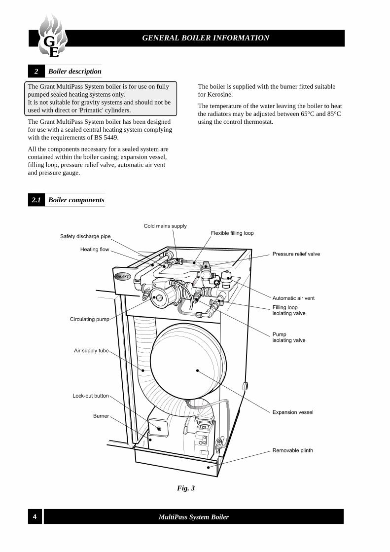
Boiler description2
GENERAL BOILER INFORMATION
The Grant MultiPass System boiler is for use on fullypumped sealed heating systems only.It is not suitable for gravity systems and should not beused with direct or 'Primatic' cylinders.
The Grant MultiPass System boiler has been designedfor use with a sealed central heating system complyingwith the requirements of BS 5449.
All the components necessary for a sealed system arecontained within the boiler casing; expansion vessel,filling loop, pressure relief valve, automatic air ventand pressure gauge.
The boiler is supplied with the burner fitted suitablefor Kerosine.
The temperature of the water leaving the boiler to heatthe radiators may be adjusted between 65°C and 85°Cusing the control thermostat.
Boiler components2.1
Fig. 3
5MultiPass System Boiler
BOILER INSTALLATION
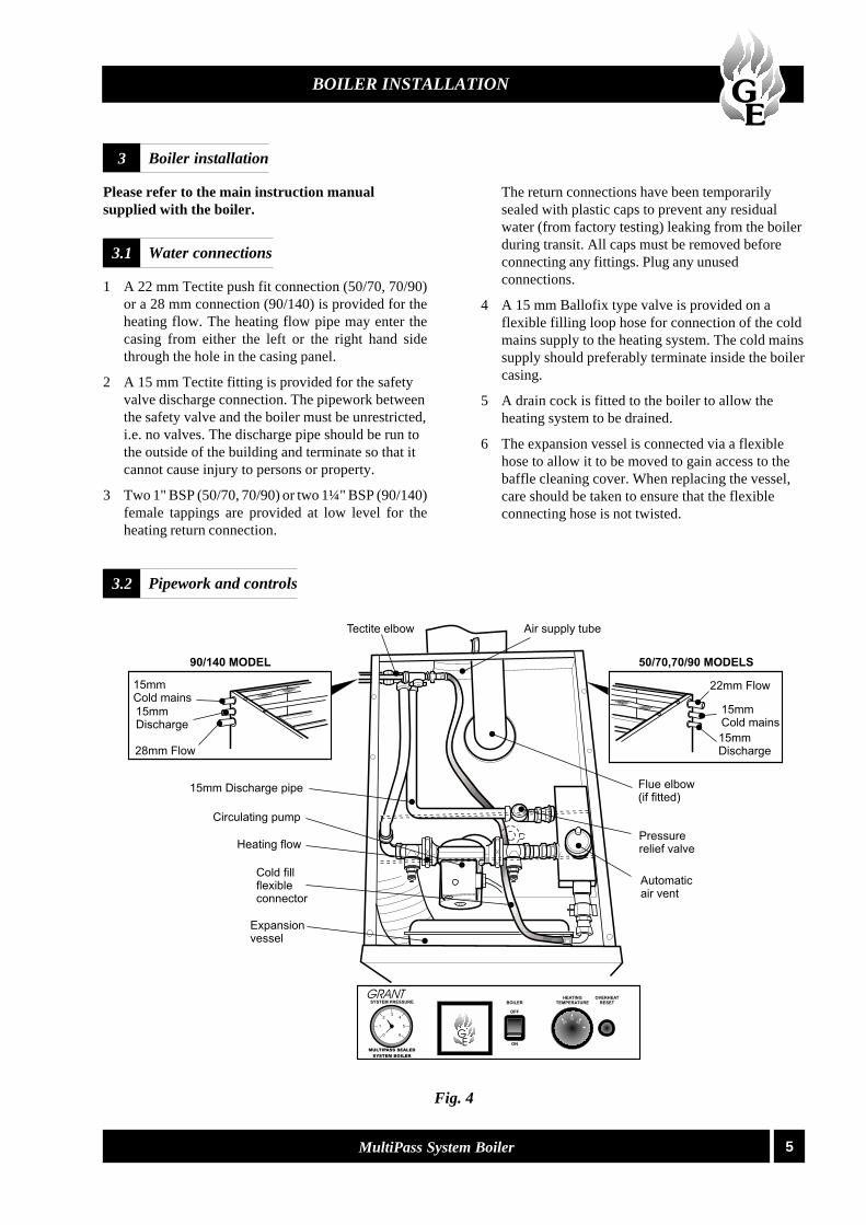
Water connections3.1
Please refer to the main instruction manualsupplied with the boiler.
1 A 22 mm Tectite push fit connection (50/70, 70/90)or a 28 mm connection (90/140) is provided for theheating flow. The heating flow pipe may enter thecasing from either the left or the right hand sidethrough the hole in the casing panel.
2 A 15 mm Tectite fitting is provided for the safetyvalve discharge connection. The pipework betweenthe safety valve and the boiler must be unrestricted,i.e. no valves. The discharge pipe should be run tothe outside of the building and terminate so that itcannot cause injury to persons or property.
3 Two 1" BSP (50/70, 70/90) or two 1¼" BSP (90/140)female tappings are provided at low level for theheating return connection.
Boiler installation3
The return connections have been temporarilysealed with plastic caps to prevent any residualwater (from factory testing) leaking from the boilerduring transit. All caps must be removed beforeconnecting any fittings. Plug any unusedconnections.
4 A 15 mm Ballofix type valve is provided on aflexible filling loop hose for connection of the coldmains supply to the heating system. The cold mainssupply should preferably terminate inside the boilercasing.
5 A drain cock is fitted to the boiler to allow theheating system to be drained.
6 The expansion vessel is connected via a flexiblehose to allow it to be moved to gain access to thebaffle cleaning cover. When replacing the vessel,care should be taken to ensure that the flexibleconnecting hose is not twisted.
Pipework and controls3.2
Fig. 4

6 MultiPass System Boiler
1 An automatic air vent is fitted to the top of theboiler. Check that the small cap on the top of theair vent is screwed on fully, then unscrew it onecomplete turn - the cap remains in this positionfrom now on.
2 If the flexible filling loop is used to fill the system,ensure it is connected and that the valve connectingit to the boiler is open and the valve at the front isclosed.A valve is open when the operating lever is in line withthe valve, and closed when it is at right angles to it.
3 Ensure that the mains cold water supply valve isopen (operating lever in line with the valve), thenturn on the mains cold water supply and graduallyopen the front valve on the filling loop until wateris heard to flow.
4 Vent each radiator in turn, starting with the lowestone in the system, to remove air.
5 It is important that the pump is properly vented toavoid it running dry and damaging its bearings. Togain access to the pump for venting it is necessaryto remove the control panel.Loosen the four fixing screws securing the panel tothe casing, push the panel towards the rear of theboiler and lower the control panel to expose thepump.Remove the cap, then unscrew and remove the plugfrom the centre of the pump. Using a suitablescrewdriver rotate the exposed spindle about oneturn. Replace the plug and cap.
6 Check the operation of the safety valve by turningthe head anticlockwise until it clicks. The click isthe safety valve head lifting off its seat allowingwater to escape from the system.Check that this is actually happening.
7 Continue to fill the system until the pressure gaugeindicates 1.0 bar. Close the fill point valve andcheck the system for water soundness, rectifyingwhere necessary. Water may be released from thesystem by manually operating the safety valve untilthe system design pressure is obtained.
8 The system design pressure (cold) should bebetween 0.5 bar and 1.0 bar. The pressure isequivalent to the maximum static head in bar + 0.3(1 bar = 10.2 metres of water), where the statichead is the vertical height from the centre of theexpansion vessel to the highest point of the system.
9 Close the valves either side of the filling loop anddisconnect the loop.
The expansion vessel fitted is supplied with acharge pressure of 1.0 bar (equivalent to a max.static head of 10.2 metres). The charge pressuremust not be less than the actual static head at thepoint of connection. Do not pressurise the vesselabove 1.5 bar.
The air pressure in the vessel must be checked annually.
The central heating system volume, using theexpansion vessel as supplied, must not exceed therecommended volumes. If the system volume isgreater, an extra expansion vessel (complying with BS4841) must be fitted as close as possible to the centralheating return connection on the boiler. The chargepressure of the extra vessel must be the same as thevessel fitted in the boiler. Refer to BS 7074:1 forfurther guidance.
The air charge pressure may be checked using a tyrepressure gauge on the expansion vessel Schraedervalve. The vessel may be re-pressurised using asuitable pump. When checking the air pressure thewater in the heating system must be cold and thesystem pressure reduced to zero.
A simple test to check if the expansion vessel size isadequate, is to fully heat the system and if the pressurerises no more than 2.3 bar the vessel is adequate. Ahigher figure indicates that an extra vessel is required.
It is recommend that the boiler should be connected toa switched mains power supply from a programmer orcontrol system. If a Grant plug-in programmer is used,a permanent 240 V mains supply (fused at 5 Amp)must be taken to the boiler. A three core cable isrequired to connect the boiler terminal block to thelive supply. Route the cable through one of the holesin the casing and pass it under the cable clamp andconnect to the terminal block as follows:
Live (brown) to terminal 1Neutral (blue) to terminal 2Earth (green/yellow) to terminal 4
Refer to the main instruction manual, supplied with theboiler, for electrical connection details and fitting ofthe optional Grant plug-in electronic programmer.
For wiring of external control systems please refer tothe wiring diagrams contained in this supplement.Please contact Grant Engineering (UK) Limited forexternal control wiring not shown.
Filling the system4
BOILER INSTALLATION
Expansion vessel pressure5
Connect the power supply6

7MultiPass System Boiler
WIRING DIAGRAMS
Boiler control panel wiring diagram6.1
Typical control system wiring diagrams6.2NOTE: If using internal programmer with noexternal controls, remove Link 1 to 9

8 MultiPass System Boiler
WIRING DIAGRAMS

9MultiPass System Boiler
COMMISSIONING
Commissioning7
It is important that the following commissioningprocedure is carried out to ensure safe and efficientoperation of the boiler.
Check that the baffles are in position and that thecleaning cover is correctly fitted and a good seal made.
1 Check that the water system has been vented andpressurised, and there are no leaks.
2 Check that all fuel line valves are open.
3 Open the boiler casing front door and remove theburner cover.
4 Connect a combined vent manifold and pressuregauge connection port on the oil pump. Open thevent screw on your vent manifold to vent thesupply while the pump is running.
5 Set the boiler On/Off switch to OFF. Check that allsystem controls are calling for heat and turn theboiler thermostat to maximum.
Switch on the electricity supply.
6 Ensure that any external controls are calling forheat. Set the boiler On/Off switch to ON. Theboiler will operate and the burner should lightwithin about 10 seconds.
If the burner does not light and the 'Lockout' resetbutton lights, wait for about 45 seconds then pressthe rest button to restart the ignition process.
This procedure may have to be repeated severaltimes during first lighting.
7 With the burner alight, check the fuel pressure.
Refer to the Technical Information sections in themain instruction manual supplied with the boiler.
Adjust the pressure if necessary.
8 Operate the boiler until it reaches normal operatingtemperature. Check the oil supply/return pipe forleaks, rectifying where necessary.
9 With the burner alight, recheck the fuel pressureand readjust if necessary. Switch the boiler off,remove the pressure gauge and replace the plug inthe pump.
10 Having ensured that there are no oil leaks, replacethe burner cover.
11 Relight the boiler and allow it to run for 20 minutesthen check the following:CO
2 level, flue gas temperature and smoke number.
Refer to the Technical Information section in themain instruction manual supplied with the boiler.
12 A flame viewing point is provided, just above theburner. Use this to view the flame not as a testpoint.
13 Check the smoke number, if satisfactory check theCO
2 level. Adjust the burner air regulator if
necessary.
14 Recheck the smoke number if the air damper hasbeen moved.
15 Under no circumstances must the smoke number beabove 1.
16 A suitable position for the air damper is one whichgives 1% less CO
2 than that which has a smoke
number of 1. It is important that the air damper iscorrectly set.
17 Check the flue gas temperature.
18 Check the boiler overheat thermostat by removingthe boiler thermostat phial (the shorter one) fromthe pocket in the top of the boiler. The boilershould switch off on the overheat thermostat.Replace the phial.Unscrew and remove the plastic cap covering thereset button, press the reset button and replace thecap.
19 When the boiler has been adjusted and is runningsatisfactorily, balance the central heating system byadjusting the radiator lock shield valves. Start withthe radiator nearest the boiler and adjust the valvesto achieve the required temperature drop acrosseach radiator.
20 Switch off the boiler.
21 With the system hot, check again for leaks,rectifying where necessary.
Drain the heating system while it is hot to completethe flushing process.
21 Refill, vent and pressurise the system as describedin section 4, adding a suitable inhibitor.
22 Replace the casing panels, if not already fitted.
Note: After commissioning the boiler you shouldcomplete the Commissioning Report on page 2 ofthe main instructions supplied with the boiler.
10 MultiPass System Boiler
INFORMATION FOR THE USER
If the boiler is to be left in service with the User, set thecontrols, timer (If optional programmer is fitted, seeinstructions supplied in kit) and room thermostat (iffitted) to the User's requirements then refer to section 8.
If the boiler is not to be handed over immediately,close the boiler fuel supply valve and switch off theelectricity supply.
If there is any possibility of the boiler being left duringfrost conditions, then the boiler and system should bedrained.
The User must be advised (and demonstrated ifnecessary) of the following important points:-
1 How to light and turn off the boiler and how tooperate the system controls.
2 The precautions necessary to prevent damage tothe central heating system and to the building, inthe event of the boiler not being in operationduring frost conditions.
3 The importance of servicing the boiler to ensuresafe and efficient operation. This should normallyonly be required once a year.
4 The type of fuel used.
5 That any servicing or replacement of parts mustonly be carried out by a suitably qualified engineer.
6 Ensure that the boiler controls and room thermostat(if fitted) are set to the User's requirements.
7 Tell the user the system pressure and show themthe position of the safety valve discharge pipe.
8 Show the User how to reset the overheat thermostatand how to restart the boiler if it goes to 'Lock-out'.
Leave these instructions and the main instructionmanual with the User.
Information for the user8

11MultiPass System Boiler

D123
SUPPLEMENT
Grant Engineering (UK) LimitedHopton House, Hopton Industrial Estate, Devizes, Wiltshire SN10 2EU
Telephone: (0870) 7775553 Fax: (0870) 7775559email: [email protected] website: www.grantuk.com
This manual is accurate at the date of printing but will be superseded and should bedisregarded if specifications and/or appearances are changed in the interests of continuedproduct improvement.
All goods sold are subject to our official Conditions of Sale, a copy of which may beobtained on application.
© Grant Engineering (UK) Limited 2003. No part of this manual may be reproduced byany means without prior written consent.
Manual compiled and designed by Publications 2000 Tel: (01670) 356211
Complies with the EC Low voltage,Electromagnetic compatibility andBoiler efficiency Directives
89/336/EEC73/23/EEC92/42/EEC