Embed Size (px)
Citation preview

SUPERVISORY CONTROL OF PARALLEL HYBRID ELECTRIC VEHICLESUSING MATLAB/ SIMULINK
SAJJAD ABDOLLAHZADEH ANBARAN
UNIVERSITI TEKNOLOGI MALAYSIA

Replace this page with the Cooperation Declaration form, which can beobtained from SPS or your faculty.

SUPERVISORY CONTROL OF PARALLEL HYBRID ELECTRIC VEHICLESUSING MATLAB/ SIMULINK
SAJJAD ABDOLLAHZADEH ANBARAN
A project report submitted in partial fulfilment of therequirements for the award of the degree ofMaster of engineering (Electrical-Power)
Faculty of Electrical EngineeringUniversiti Teknologi Malaysia
JULY 2012

iii
"To my parents, beloved brothers and sisters"

iv
ACKNOWLEDGEMENT
Praise be to Allah, The Lord of universe. Only with His uncountable favorsthat I can finish this work. Wish He accept all of my faithful learning efforts as theway I sincerely express my gratefulness.
First and foremost, I would like to express my sincere gratitude toward mysupervisor, Assoc.Prof. Nik Rumzi bin Nil Idris , for his advanced guidance, constantassistance, technical suggestions and encouragement in making this project a success.
Furthermore, I thank all the personnel at Universiti Teknologi Malaysia (UTM)for their effort to provide an interesting program and a nice working environment.
Last but not least, I dedicate my thesis to my family, especially my parents,who continuously provided me love and support in accomplishing my study.
Skudai, Johor - Malaysia
Sajad A.Anbaran

v
ABSTRACT
Due to the limitation of fossil fuels and the high consumption rate of this energyfor transportation, inclination of vehicle industry toward other sources of energy isinevitable. Electric vehicles and hybrid vehicles could be a good solution. Thanks tothe state of art electric motors, power electronics, embedded power train controller,energy storage systems like batteries and ultra capacitors, the performance of thevehicle could become more and more energy efficient. Since the integrating of all thesecomponents in a drive train configuration could be a challenge for the manufacturer,computer simulation and modeling before prototyping could be really beneficial interms of cost, safety and design performance.The main objective of this study is to establish a systematic approach to parallel hybridelectric vehicle modeling and simulation as well as implementation of the supervisorycontrol in order to improve system efficiency and reduce fuel consumption. Thisthesis offers an overview of the various applied control strategies in hybrid electricvehicles, specifically to the parallel hybrid electric vehicle. Several control strategiesare described in literature as well as important of supervisory control strategy in hybridelectric vehicle and the difference in terms of energy management is discussed.Different hybrid power-train configuration are presented and explained in thisthesis. Hybrid electric vehicle driveline components including electric motor, vehicledynamic, internal combustion engine and electric energy storage are illustrated. Inaddition, some of the principles of modeling and simulation are discussed and differentmethods of modeling are presented. A detailed parallel hybrid vehicle modelingand simulation in Matlab environment using Simscape toolbox is presented. A rule-based supervisory control strategy using Simulink/Stateflow is applied to controlhybrid vehicle in order to operate parallel hybrid driveline component in their optimalregion and consequently to achieve high-performance low-emission hybrid drive-train.Simulation results for the major components of hybrid driveline are presented todemonstrate the effectiveness of this supervisory control strategy.
vi
ABSTRAK
Disebabkan oleh bahan api fosil yang terhad dan kadar penggunaan bahanapi ini yang tinggi bagi kegunaan pengangkutan, kecenderungan industri automotifuntuk berubah kepada sumber tenaga lain tidak dapat dielakkan. Kenderaanelektrik dan hibrid merupakan satu penyelesaian yang terbaik. Terima kasih kepadakemampuan motor elektrik, elektronik kuasa, pengawal pemacu, sistem penyimpantenaga seperti bateri and kapasitor ultra, prestasi kenderaan ini mampu menjadilebih baik lagi. Disebabkan oleh penggunaan komponen-komponen ini dalam sistemkonfigurasi pemacu menjadi satu cabaran kepada industri pembuatan kenderaan,simulasi komputer dan pemodelan sebelum penghasilan prototaip mampu memberimanfaat dari segi kos, keselamatan dan rekabentuk.Objektif utama kajian ini adalah untuk menghasilkan satu kaedah pendekatansistematik untuk pemodelan dan penyelakuan kenderaan hibrid elektrik selariserta perlaksanaan kawalan penyeliaan bagi menambah baik kecekapan sistem danmengurangkan penggunaan bahan api. Thesis ini membentangkan tinjauan tentangpelbagai strategi kawalan bagi kenderaan elektrik hibrid, khususnya kenderaan elektrikhibrid selari. Beberapa strategi kawalan yang telah dihasilkan beserta kepentinganstrategi penyeliaan kawalan di dalam kenderaan elektrik hibrid serta perbezaan darisegi pengurusan tenaga juga dibincangkan.Perbezaan konfigurasi pemacu hibrid akan dibentang dan dibincangkan dalamthesis ini. Komponen kenderaan elektrik pemacuan seperti motor elektrik,dinamik kenderaan, enjin pembakaran dalaman dan penyimpan tenaga elektrikjuga disampaikan. Disamping itu, beberapa prinsip permodelan dan simulasi jugadibincangkan dan kepelbagaian teknik permodelan dibentangkan. Satu peneranganterperinci mengenai permodelan kenderaan hibrid selari dan simulasi di dalampersekitaran Matlab menggunakan Simscape dibentangkan. Strategi berasaskan syaratuntuk strategi kawalan penyeliaan menggunakan Simulink/Stateflow telah digunakandalam kawalan kenderaan hibrid untuk memastikan komponen pemacu beroperasisecara optima dan seterusnya mencapai kecekapan tinggi serta perlepasan pencemaranudara yang rendah. Keputusan simulasi untuk komponen utama dalam pemacuanhibrid dibentangkan bagi menunjukkan keberkesanan kaedah penyeliaan kawalan ini.

vii
TABLE OF CONTENTS
CHAPTER TITLE PAGE
DECLARATION iiDEDICATION iiiACKNOWLEDGEMENT ivABSTRACT vABSTRAK viTABLE OF CONTENTS viiLIST OF TABLES xLIST OF FIGURES xi
1 INTRODUCTION 11.1 Background of the study 11.2 Statement of the problem 31.3 Purpose of the study 31.4 Objectives of the study 41.5 Significant and scope of the study 4
2 LITERATURE REVIEW 52.1 Introduction 52.2 A breif history of HEVs 62.3 Architecture of Hybrid Electric Drive Train 7
2.3.1 Series Hybrid Electric Drive Train 72.3.2 Parallel Hybrid Electric Drive Train 92.3.3 Drive train components 11
2.3.3.1 Internal Combustion Engine 112.3.3.2 The ICE modelling 12
2.3.4 The electric machines 142.3.5 The energy storage System 17
2.3.5.1 The battery 172.3.5.2 Capacitors 19
viii
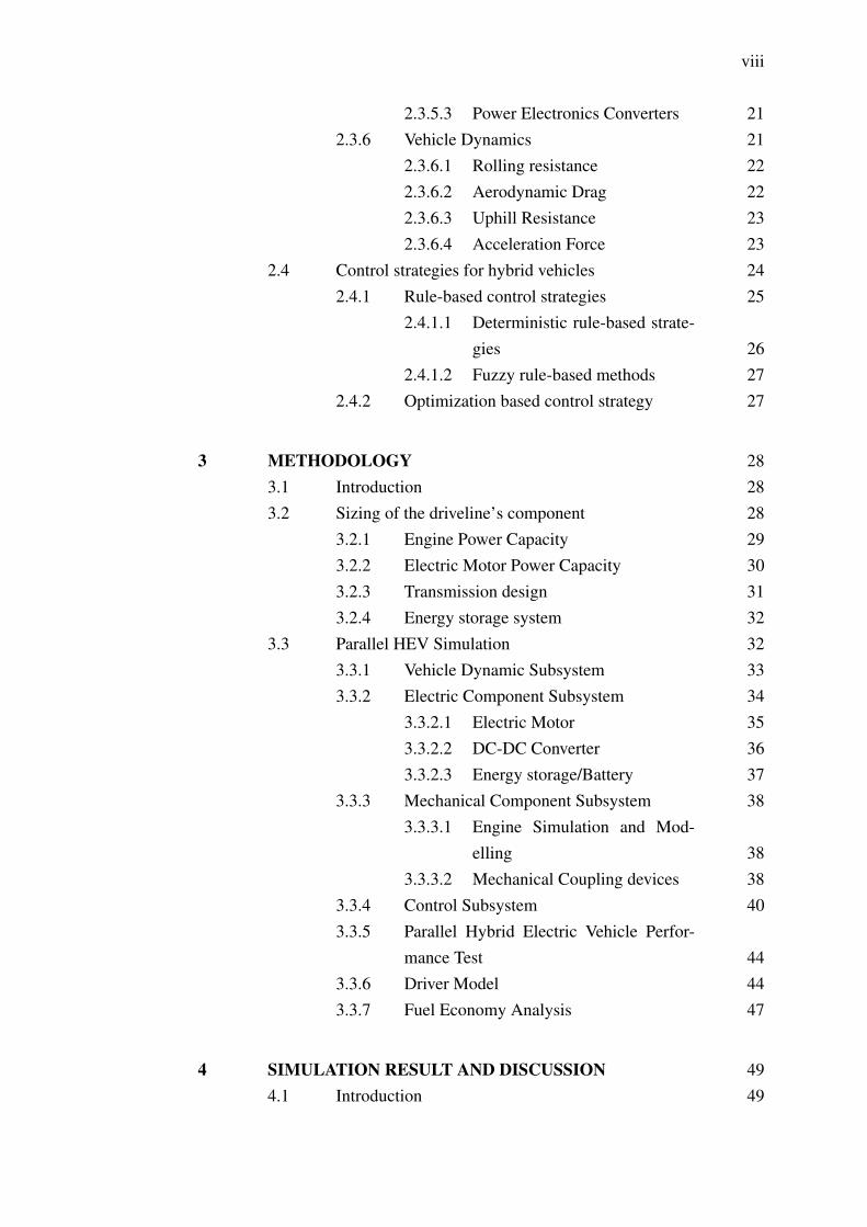
2.3.5.3 Power Electronics Converters 212.3.6 Vehicle Dynamics 21
2.3.6.1 Rolling resistance 222.3.6.2 Aerodynamic Drag 222.3.6.3 Uphill Resistance 232.3.6.4 Acceleration Force 23
2.4 Control strategies for hybrid vehicles 242.4.1 Rule-based control strategies 25
2.4.1.1 Deterministic rule-based strate-gies 26
2.4.1.2 Fuzzy rule-based methods 272.4.2 Optimization based control strategy 27
3 METHODOLOGY 283.1 Introduction 283.2 Sizing of the driveline’s component 28
3.2.1 Engine Power Capacity 293.2.2 Electric Motor Power Capacity 303.2.3 Transmission design 313.2.4 Energy storage system 32
3.3 Parallel HEV Simulation 323.3.1 Vehicle Dynamic Subsystem 333.3.2 Electric Component Subsystem 34
3.3.2.1 Electric Motor 353.3.2.2 DC-DC Converter 363.3.2.3 Energy storage/Battery 37
3.3.3 Mechanical Component Subsystem 383.3.3.1 Engine Simulation and Mod-
elling 383.3.3.2 Mechanical Coupling devices 38
3.3.4 Control Subsystem 403.3.5 Parallel Hybrid Electric Vehicle Perfor-
mance Test 443.3.6 Driver Model 443.3.7 Fuel Economy Analysis 47
4 SIMULATION RESULT AND DISCUSSION 494.1 Introduction 49

ix

x
LIST OF TABLES
TABLE NO. TITLE PAGE
3.1 Engine parameters 303.2 Battery specification 324.1 Parallel HEV fuel economy based on stuided driving
cycles 76

xi
LIST OF FIGURES
FIGURE NO. TITLE PAGE
2.1 Functional block diagram of a series hybrid vehicle 82.2 Configuration of a series hybrid vehicle 82.3 Functional diagram of the parallel hybrid electric vehicle 102.4 Configuration of the parallel hybrid drive train 112.5 Schematic of typical 4S, gasoline engine 122.6 Power, Torque and SPC characteristics for ICE 132.7 SPC and efficiency of the typical ICE at different load
condition 132.8 Engine Static Model 132.9 A typical Electric Motor efficiency map 152.10 The Electric machine in generating mode 162.11 Motoring Mode 162.12 General Model of energy storage system[3] 182.13 Battery Circuit Model 192.14 Circuit model of super-capacitor pack 202.15 Acted Forces on vehicle 212.16 Classification of the hybrid power train control strategy 253.1 Motor torque-speed characteristics 313.2 Dynamic conceptual block diagram 333.3 Vehicle dynamic subsystem in Matlab/Simulink 343.4 Functional diagram of a typical electric propulsion
system 353.5 Electric motor Simulation in Simulink/Simscape 353.6 Motor torque-speed characteristics inserted in servomo-
tor block 363.7 DC/DC converter model in Simulink/Simscape 373.8 Battery Model in Simulik/Simscape 373.9 Engine simulation in Matlab/Simulink environment 383.10 Conceptual configuration of the speed coupling parallel
HEV 39

xii
3.11 Planetary gear unit 403.12 Hybrid electric drive train with speed coupling of
planetary gear 403.13 Parallel HEV overall control scheme 413.14 Parallel HEV supervisory control strategy 423.16 Parallel HEV various operating mode 433.15 Parallel HEV supervisory control logic in stateflow 433.17 ECE 15 Cycle 443.18 EUDC Cycle 453.19 EUDC Cycle for low power Vehicles 453.20 FTP-72 Cycle 463.21 Self-defined Drive cycle 463.22 Driver Model block in Matlab/Simulink 473.23 Parallel HEV fuel economy 484.1 Vehicle output speed for ECE 15 drive cycle 504.2 EM gnerator torque for motion mode and regenerative
mode 514.3 Power generation for driving based on ECE 15 524.4 ICE generated torque 524.5 ICE throttle control signal 534.6 ICE output speed 544.7 Automative driver (Accelerator ) control signal 554.8 Electric characteristics of the dc bus 554.9 Battery SOC characteristics for ECE 15 564.10 Vehicle output speed for EUDC cycle 574.11 ICE power genratrion for EUDC 574.12 Engine speed under EUDC driving condition 584.16 Battery SOC characteristics based on EUDC 584.13 Engine throttle command 594.14 Accelerator command signal 594.15 Generated torque by EM 604.17 Vehicle dc bus characteristics 604.18 Vehicle output speed 614.19 Power generation by ICE 624.20 Produce torque by ICE 624.21 Throttle command to ICE 634.22 ICE speed (rpm) 634.23 Accelerator command signal based on EUDC 644.24 Generated torque by EM 64

xiii
4.25 Battery SOC characteristics 654.26 Vehicle output speed 664.27 ICE power generation on the basis of the FTP drive cycle 664.29 Engine Speed (rpm) based on FTP 72 674.28 ICE torque generation based on the FTP drive cycle 674.30 Automative driver command signal 684.31 Engine speed control throttle command signal 684.32 Motor Torque generation characteristics based on FTP
72 694.33 Battery State of Charge characteristics for FTP 72 694.34 DC bus electrical characteristics 704.35 vehicle output speed 714.36 Engine speed, rpm 714.37 Delivered torque to the load by ICE 724.38 Delivered power to the driveline by ICE 724.39 Throttle command to ICE 734.40 EM torqe baed on self-defined test driving cycle 734.41 Automative driver command to the control unit 744.42 DC/DC bus characteristics 744.43 Battery SOC characteristics 75

xiv
LIST OF ABBREVIATIONS
EV - Electric Vehicle
HEV - Hybrid Electric Vehicle
ICE - Internal Combustion Engine
SOC - State Of Charge
EM - Electric Machine
xv
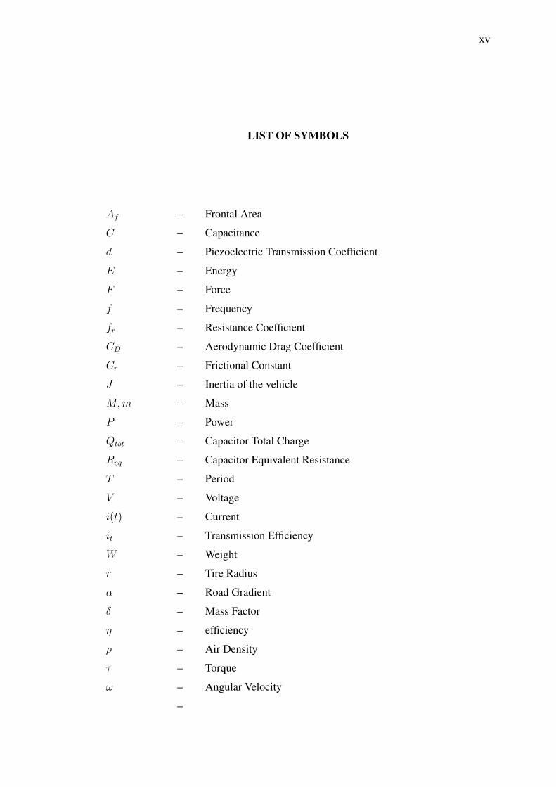
LIST OF SYMBOLS
Af – Frontal Area
C – Capacitance
d – Piezoelectric Transmission Coefficient
E – Energy
F – Force
f – Frequency
fr – Resistance Coefficient
CD – Aerodynamic Drag Coefficient
Cr – Frictional Constant
J – Inertia of the vehicle
M,m – Mass
P – Power
Qtot – Capacitor Total Charge
Req – Capacitor Equivalent Resistance
T – Period
V – Voltage
i(t) – Current
it – Transmission Efficiency
W – Weight
r – Tire Radius
α – Road Gradient
δ – Mass Factor
η – efficiency
ρ – Air Density
τ – Torque
ω – Angular Velocity
–

CHAPTER 1
INTRODUCTION
1.1 Background of the study
The sharp rise in petroleum consumption and fuel importing and consequentlydetrimental environmental effects of the fuel consuming tool cause serious concernon the economy and environment in the most countries. According to statistics,transportation is the one the most fuel consuming sectors. Two third of the importedpetroleum in the developed countries are being consumed in transportation sector.
Since the dominant meant of the transportation has been in the form of thepersonal automobiles, this area has gained more attention. Limited domestic oil naturalreserves and the extensive use of the personal cars have led to some economicalconcern and countries dependence to foreign oil markets. Half of consumed petroleumin the USA were imported. This shows the extend of the country’s economyvulnerability to varying petroleum price and other related issues.
Owing to the fact that personal transportation has significant contributionto fuel consuming sector there still exist some hinder for automobile manufacturerproduction to meet related regulation regarding to vehicles performance, noise andharmful emission. Hence, Improvement of the fuel consumption and overall energyefficiency is one of the most important subjects for developing and designing newvehicles technologies. It is understandable that there exist a contrast between globalconcern on sustainable energy use and environmental protection. This contradictoryclearly call for new technology to play fundamental role. The promising technology toovercome on these obstacles to meet regulations are exploitation of alternative energysources in vehicle power-train, improving fuel economy and reducing the harmfulemission.

2
The new vehicle technology appeared in the forms of Electric Vehicle (EV),fuel cell vehicles, Hybrid Electric Vehicle (HEV). Among alternative power-trainsolution being investigated, HEVs due to their major advantages on other vehiclesare more popular. In general, HEVs have two power sourcesto run the tractionsimultaneously or respectively in order to propel the vehicle wheels. Moreover, theHEVs are more efficient and performed better with compare to conventional engines.In some controlling circumstances HEVs can be run in zero emission vehicle (ZEV)state. So this fact made HEVs a important player in today’s automobile market.
Since research and analyzing is a time consuming process, computer basedsimulation and modelling is an approach to deal with this limitation. Virtualprototyping, however, can be used to reduce the expenses and the length of the designcycle. Variety of the vehicle simulator such as SIMPLEV, HVEC, CarSim, ADVISORand so on are available.
Many studies and researches have been carried out on hybrid electric vehicles.However, most of them used different simulation and modelling tools to perform theirstudy. In the reference [10] a series hybrid and electric vehicle drive-train is modelledand simulated on PSCAD which is a transient simulation program. In additionin references [3], [14], [15],[16],[17],[18] various topologies of the hybrid electricvehicle have been investigated. In ref [1] PSAT is used to analyze performance ofthe HEV. Furthermore, researcher in ref[14] modeled and compared in both HEVSIMand ADVISOR then simulation results which is more accurate were compared. Onthe other hand, many technical control strategies have been proposed and at the sametime investigated by references [8], [5], [1], [11] in which in ref [12] authors tried tointroduce new vehicle controlling to fully meet driver desires. Past control methodswere sensitive to different driving habits and vehicle parameters variation. Thusresearcher in ref [12] has implemented neural network concept as control strategy toeliminate this flaw. Moreover, in ref [6], [19] several available types of batteries in theADVISOR library are introduced. In addition, the temperature impact on the vehicleperformance and life cycle of the battery is studied. Finally, a optimization study hasbeen conducted to achieve low-weight and more fuel-economy HEV in ref [2].

3
1.2 Statement of the problem
It is evident that the great amount of the fuel is being consumed bypersonal transportation and they have significant contribution on harmful emissions.Therefore, increasing concerns about environmental issues such as global warmingand greenhouse emissions as well as natural oil sources depletion have made energyefficiency and being environmentally friendly as primary selling point for automobiles.In spite of the fact that HEVs offer some important advantages in comparisonto conventional engines, their configuration comprise more component and greatercomplexity with higher initial price. Thus, implementation of the simulator softwareto predict the behaviour of the vehicular system under various circumstances areinevitable.
Compared to conventional vehicles, hybrid electric vehicles consist of morecomponent (electrically and mechanically) and this increase the complexity of thevehicle system. In addition to these electrification component and subsystems, thedynamic analysis of the various component interaction becomes difficult. Modellingand simulation are absolutely necessary for concept evaluation, prototyping andanalysis of the newly design HEV. Therefore, a modelling and simulation environmentto model subsystems, embedded software and component is needed[2] .
In the other word, in order to realize the benefits of HEVs, the designs mustbe extensively modelled and refined before improved emissions and fuel economy canbe implemented on a large scale. This will require accurate, flexible simulation tools,which will expedite the design processes for HEVs. This will enable engineers tocompare the relative performance of one design to another and concentrate on the bestdesigns.
1.3 Purpose of the study
with an increasing growth of the concerns about environmental related issueswhich is partly contributed by the passengers cars in harmful emissions draws attentionto this sector. Furthermore, the selection and analysis of the appropriate propulsionsystems role in the reduction of the fuel consuming, long travelling range and efficiencyare considerable.

4
This increasing demand for more implementation of the fuel economy andefficient vehicles cause automobile designer to shift toward the design of newgeneration power-trains beyond the conventional (fuel-only) engines. Hence, thevehicles hybridization and enhanced design leads to fulfil the constraints andregulations on petroleum and environment. Simulation is one the efficient way in thedesign and analysis of different levels of the propulsion system before physical testingand construction begins. Furthermore, it provide this capability to examine variouscontrol strategy to have efficient running of the vehicle. The purpose of this study isto achieve greater understanding of the HEVs design and simulation, as well as, theirimpact on environment.
1.4 Objectives of the study
The objective of this study are:
• To simulate parallel configuration of the Hybrid Electric Vehicle usingMatlab/Simulink
• To implement supervisory control of the HEV to optimal operation of the hybridvehicle’s component using stateflow toolbox of the MATLAB/Simulink.
• To investigate HEV’s environmental impact
• To compare different topologies of the HEV in terms of their performance, fuelconsumption and emission.
• To achieve more understanding of the Hybrid Electric Vehicles.
1.5 Significant and scope of the study
Currently many studies there are have been carried out to model and simulateof the different topologies of the HEVs. The result of this study can be used as partof the approach to new vehicle component selection. Therefore, the evaluation ofthe vehicle performance criteria including gradeability, acceleration, driving range,pollution, energy consumption will be the scope of this study[3].

80
REFERENCES
1. Zoroofi, S., Modeling and Simulation of Vehicular Power Systems in Department of Energy and Environment. 2008, CHALMERS UNIVERSITY OF TECHNOLOGY: Göteborg, Sweden.
2. Gao, D.W., C. Mi, and A. Emadi, Modeling and Simulation of Electric and Hybrid Vehicles. Proceedings of the IEEE, 2007. 95(4): p. 729-745.
3. Ahmad A, P., Battery thermal models for hybrid vehicle simulations. Journal of Power Sources, 2002. 110(2): p. 377-382.
4. Hybrid Electric Vehicles, in Modern Electric, Hybrid Electric, and Fuel Cell Vehicles. 2009, CRC Press. p. 123-150.
5. EMMA GRUNDITZ and E.J, MODELING AND SIMULATION OF THE HYBRID ELECTRIC VEHICLE FOR SHELL ECO-MARATHON AND ELECTRIC GO-KART, in THE ENERGY AND ENVIRONMENT. 2009, CHALMERS UNIVERSITY OF TECHNOLOGY CHALMERS.
6. Trzynadlowski and Andrzej, INTRODUCTION TO MODERN POWER ELECTRONICS. 2nd ed. 2010.
7. Environmental Impact and History of Modern Transportation, in Modern Electric, Hybrid Electric, and Fuel Cell Vehicles. 2009, CRC Press. p. 1-18.
8. James Larmine, J.L., Electric Vehicle Technology Explained. 2nd ed. 2003: John Wiley & Sons.
9. Momoh, O.D. and M.O. Omoigui. An overview of hybrid electric vehicle technology. in Vehicle Power and Propulsion Conference, 2009. VPPC '09. IEEE. 2009.
10. Parallel (Mechanically Coupled) Hybrid Electric Drive Train Design, in Modern Electric, Hybrid Electric, and Fuel Cell Vehicles. 2009, CRC Press. p. 281-308.
11. Sorrentino, M., G. Rizzo, and I. Arsie, Analysis of a rule-based control strategy for on-board energy management of series hybrid vehicles. Control Engineering Practice, 2011. 19(12): p. 1433-1441.
12. Internal Combustion Engines, in Modern Electric, Hybrid Electric, and Fuel Cell Vehicles. 2009, CRC Press. p. 67-104.
13. Peaking Power Sources and Energy Storages, in Modern Electric, Hybrid Electric, and Fuel Cell Vehicles. 2009, CRC Press. p. 375-410.
14. Rodatz, P., et al., Optimal power management of an experimental fuel cell/supercapacitor-powered hybrid vehicle. Control Engineering Practice, 2005. 13(1): p. 41-53.
15. Salmasi, F.R., Control Strategies for Hybrid Electric Vehicles: Evolution, Classification, Comparison, and Future Trends. Vehicular Technology, IEEE Transactions on, 2007. 56(5): p. 2393-2404.
16. Çağatay Bayindir, K., M.A. Gözüküçük, and A. Teke, A comprehensive overview of hybrid electric vehicle: Powertrain configurations, powertrain control techniques and electronic control units. Energy Conversion and Management, 2011. 52(2): p. 1305-1313.
17. Design and Control Principles of Plug-In Hybrid Electric Vehicles, in Modern Electric, Hybrid Electric, and Fuel Cell Vehicles. 2009, CRC Press. p. 333-352.
81
18. Technical Overview of Toyota Prius, in Modern Electric, Hybrid Electric, and Fuel Cell Vehicles. 2009, CRC Press. p. 499-518.
19. John, M.M., Propulsion Sysyem for Hybrid Vehicle 2010, IET.20. Pisu, P. and G. Rizzoni, A Comparative Study Of Supervisory Control
Strategies for Hybrid Electric Vehicles. Control Systems Technology, IEEE Transactions on, 2007. 15(3): p. 506-518.
21. Pisu, P., K. Koprubasi, and G. Rizzoni. Energy Management and Drivability Control Problems for Hybrid Electric Vehicles. in Decision and Control, 2005 and 2005 European Control Conference. CDC-ECC '05. 44th IEEE Conference on. 2005.
22. Jinsong, Z., et al. A Simulation Method of Controlled Hybrid Petri Nets Based on Matlab Simulink/Stateflow. in Automation and Logistics, 2007 IEEE International Conference on. 2007.
23. Gou, J., et al. Acceleration Slip Regulation of Electric Vehicle. in Logistics Engineering and Intelligent Transportation Systems (LEITS), 2010 International Conference on. 2010.
24. Andong, Y., Z. Han, and Z. Bingzhan. Control of Hybrid Electric Bus based on hybrid system theory. in Electric Information and Control Engineering (ICEICE), 2011 International Conference on. 2011.
25. Vijay, E.V., et al. Electronic control unit for an adaptive cruise control system & engine management system in a vehicle using electronic fuel injection. in Emerging Trends in Robotics and Communication Technologies (INTERACT), 2010 International Conference on. 2010.
26. Guoqiang, A., et al. Model-based energy management strategy development for hybrid electric vehicles. in Industrial Electronics, 2008. ISIE 2008. IEEE International Symposium on. 2008.
27. Salisa Abdul Rahman, N.A.a.J.Z., Modeling and simulation of an Energy Management System for Plug-in Hybrid Electric Vehicles, in Australian University Power engineering Conference (AUPEC'08). 2008. p. 274-280.
28. Ferreira, A.A., et al., Energy Management Fuzzy Logic Supervisory for Electric Vehicle Power Supplies System. Power Electronics, IEEE Transactions on, 2008. 23(1): p. 107-115.
29. Poursamad, A. and M. Montazeri, Design of genetic-fuzzy control strategy for parallel hybrid electric vehicles. Control Engineering Practice, 2008. 16(7): p. 861-873.
30. serrao, L., a comparative analysis energy management strategies for hybrid electric vehicles in Mechanical Engineering 2009, Ohio State university ohio
31. Butler, K.L., M. Ehsani, and P. Kamath, A Matlab-based modeling and simulation package for electric and hybrid electric vehicle design. Vehicular Technology, IEEE Transactions on, 1999. 48(6): p. 1770-1778.
32. Cole, G., Simple electric vehicle simulation (SIMPLEV), DOE Idaho National Eng. Lab.
33. Marr, W.W. and W.J. Walsh, Life-cycle cost evaluations of elec-tric/hybrid vehicles. Energy Conversion Management, 1992. vol. 33(no. 9): p. 849–853.
34. Bumby, J.R., Computer modeling of the automotive energy re-quirements for internal combustion engine and battery electric-powered vehicles. Proc. Inst. Elect. Eng, 1985. 132(5): p. 256-279.
35. Markel, T., et al., ADVISOR: a systems analysis tool for advanced vehicle modeling. Journal of Power Sources, 2002. 110(2): p. 255-266.

82
36. Jun, H. and G. Xuexun. Modeling and simulation of hybrid electric vehicles using HEVSIM and ADVISOR. in Vehicle Power and Propulsion Conference, 2008. VPPC '08. IEEE. 2008.
37. Li, Y.-L., X.-S. Zhang, and L. Cai, A novel parallel-type hybrid-power gas engine-driven heat pump system. International Journal of Refrigeration, 2007. 30(7): p. 1134-1142.
38. Fish, S. and T.B. Savoie, Simulation-Based OPtimal Sizing of Hybrid Electric Vehicle Components for Specific Combat Missions. IEEE Transaction on Magnetics 2001. 37(1): p. 485-488.
39. Delprat, S., et al., Control of a parallel hybrid powertrain: optimal control.Vehicular Technology, IEEE Transactions on, 2004. 53(3): p. 872-881.
40. Jong-Seob, W., R. Langari, and M. Ehsani, An energy management and charge sustaining strategy for a parallel hybrid vehicle with CVT. Control Systems Technology, IEEE Transactions on, 2005. 13(2): p. 313-320.
41. Doerffel, D.a.A.-S., Suleiman, System modeling and simulation as a tool for developing a vision for future hybrid electric vehicle drivetrain configurations, in IEEE Vehicle Power and Propulsion Conference (VPPC). 2006.
42. Hyeoun-Dong, L., et al., Torque control strategy for a parallel-hybrid vehicle using fuzzy logic. Industry Applications Magazine, IEEE, 2000. 6(6): p. 33-38.
43. Electric Propulsion Systems, in Modern Electric, Hybrid Electric, and Fuel Cell Vehicles. 2009, CRC Press. p. 151-251.
44. A.Bouscayrol, S.A.Syed, and W.Lhomme, Modelling Comparison of Planetary Gear using EMR and Simdriveline for Hybrid Electric Vehicles in IEEE. 2009. p. 1835-1841.
45. Yimin, G. and M. Ehsani, A torque and speed coupling hybrid drivetrain-architecture, control, and simulation. Power Electronics, IEEE Transactions on, 2006. 21(3): p. 741-748.
46. Yimin, G., M. Ehsani, and J.M. Miller. Hybrid Electric Vehicle: Overview and State of the Art. in Industrial Electronics, 2005. ISIE 2005. Proceedings of the IEEE International Symposium on. 2005.