Embed Size (px)
Citation preview
8
Supervision and Control Strategies of a 6 DOF Parallel Manipulator
Using a Mechatronic Approach
João Mauricio Rosário1, Didier Dumur2, Mariana Moretti1, Fabian Lara1 and Alvaro Uribe1
1UNICAMP, Campinas, SP, 2SUPELEC, Gif-sur-Yvette,
1Brazil 2France
1. Introduction
Currently, the Stewart Platform is used in different engineering applications (machine tool
technology, underwater research, entertainment, medical applications surgery, and others)
due to its low mechatronic cost implementation as an alternative to conventional robots. The
current trend of using parallel manipulators has created the need for developing open
supervision and control architectures. This chapter presents the mathematical analysis,
simulation, supervision and control implementation of a six degree of freedom (DOF)
parallel manipulator known as the Stewart platform. The related studies are critically
examined to ascertain the research trends in the field. An analytical study of the kinematics,
dynamics and control of this manipulator covers the derivation of closed form expressions
for the inverse Jacobian matrix of the mechanism and its time derivative, the evaluation of a
numerical iterative scheme for forward kinematics on-line solving, the effects of various
configurations of the unpowered joints due to angular velocities and accelerations of the
links, and finally the Newton-Euler formulation for deriving the rigid body dynamic
equations.
The contents of this chapter are organized as follows:
• Section II presents the features of a Stewart Platform manipulator, describing its spatial
motion and applications.
• Section III covers the mathematical description, with the kinematics and dynamics
modelling, and the actuator control using a mechatronic prototyping approach.
• Section IV details the control structure, and compares two different control strategies:
the PID joint control structure and the Generalized Predictive Control (GPC). Both
controllers structured in the polynomial RST form, as a generic framework for
numerical control laws satisfying open architecture requirements.
• Section V describes the supervision and control architecture, particularly the spatial
tracking error is analyzed for both controllers.
www.intechopen.com
Advanced Strategies for Robot Manipulators
174
• Section VI provides time domain simulation results and performance comparison for several scenarios (linear and circular displacements, translational or rotational movements), using reconfigurable computing applied to a Stewart-Gough platform.
• Section VII presents the supervisory control and hardware interface implemented in a LabviewTM environment.
• Finally, section VII presents the conclusions and contributions.
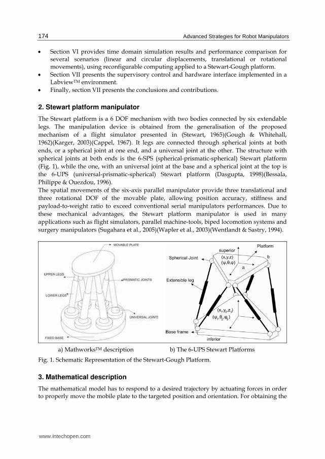
2. Stewart platform manipulator
The Stewart platform is a 6 DOF mechanism with two bodies connected by six extendable
legs. The manipulation device is obtained from the generalisation of the proposed
mechanism of a flight simulator presented in (Stewart, 1965)(Gough & Whitehall,
1962)(Karger, 2003)(Cappel, 1967). It legs are connected through spherical joints at both
ends, or a spherical joint at one end, and a universal joint at the other. The structure with
spherical joints at both ends is the 6-SPS (spherical-prismatic-spherical) Stewart platform
(Fig. 1), while the one, with an universal joint at the base and a spherical joint at the top is
the 6-UPS (universal-prismatic-spherical) Stewart platform (Dasgupta, 1998)(Bessala,
Philippe & Ouezdou, 1996).
The spatial movements of the six-axis parallel manipulator provide three translational and
three rotational DOF of the movable plate, allowing position accuracy, stiffness and
payload-to-weight ratio to exceed conventional serial manipulators performances. Due to
these mechanical advantages, the Stewart platform manipulator is used in many
applications such as flight simulators, parallel machine-tools, biped locomotion systems and
surgery manipulators (Sugahara et al., 2005)(Wapler et al., 2003)(Wentlandt & Sastry, 1994).
a) MathworksTM description b) The 6-UPS Stewart Platforms
Fig. 1. Schematic Representation of the Stewart-Gough Platform.
3. Mathematical description
The mathematical model has to respond to a desired trajectory by actuating forces in order to properly move the mobile plate to the targeted position and orientation. For obtaining the
www.intechopen.com
Supervision and Control Strategies of a 6 DOF Parallel Manipulator Using a Mechatronic Approach
175
mathematical representation, a reference coordinated system for analyzing the manipulator is presented in Fig. 1.
3.1 Geometric model Given the accomplishment of numerous tasks due to its configuration, the platform legs are
identical kinematics chains whose motion varies accordingly to the tip of the joint used
(Fasse & Gosselin, 1998)(Boney, 2003). Typically, the legs are designed with an upper and
lower adjustable body, so each one has a variable length (Fig. 1). The geometrical model of a
platform is expressed by its (X, Y, Z) position and the (ψ, θ, φ) orientation due to a fixed
coordinate system linked at the base of the platform. The obtained function of this
generalized coordinates (joints linear movements), is presented in (1).
( )i iX f L= (1)
where 1 2 6( )iL L L L= A are each joint linear position, ( )iX X Y Z ψ θ ϕ= the
position-orientation vector of a point of the platform. Then the transformation matrix for
rotations can be organised as Shown in (2), where, cψ: cos ψ, sψ: sin ψ
( , , ) rot( , )rot( , )rot( , )
c c c s s s c c s c s s
T x y z s c s s s c c s s c c s
s c s c c
ϕ θ ϕ θ ψ ϕ ψ ϕ θ ψ ϕ ψψ θ ϕ ϕ θ ψ ϕ θ ϕ θ ψ ϕ ψ ϕ θ ψ ϕ ψ
θ θ ψ θ ψ− − +⎡ ⎤⎢ ⎥= = − + −⎢ ⎥⎢ ⎥−⎣ ⎦
(2)
where, ⎥⎥⎦⎤
⎢⎢⎣⎡
+−=
yx
Z
nsnc
nATAN φφθ 2 , ⎥⎦
⎤⎢⎣⎡=
x
y
n
nATAN 2φ , ⎥⎥⎦
⎤⎢⎢⎣⎡
+−−=
yx
yx
scφssφacφasφ
ATANψ 2 and
[ ]zyx
nnn=n , [ ]zyx
sss=s , [ ]zyx
aaa=a : are the orthonormal vectors that describe
the platform's orientation.
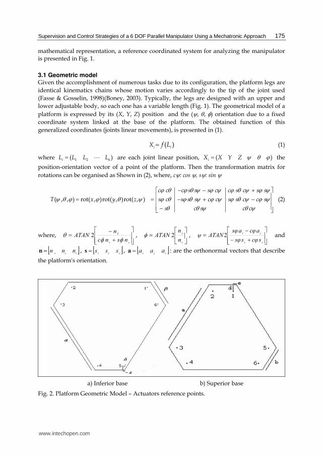
a) Inferior base b) Superior base
Fig. 2. Platform Geometric Model – Actuators reference points.
www.intechopen.com
Advanced Strategies for Robot Manipulators
176
This transformation matrix allows changing each actuator's position into a new configuration in order to define the kinematics model as shown in Fig.2 (Kim, Chungt & Youmt, 1997)(Li & Salcudean, 1997). The points that define the upper base motion are located at the extremities of the six linear actuators fixed at the lower base of the platform. When assuming that the actuators have reached their final position and orientation, the problem is calculating the coordinates of the center of mass on the superior base, and the RPY orientation angles (roll, pitch and yaw). The relative positions can be calculated from the position and orientation analysis (using the transformation matrix), leading to new ones within the platform’s workspace.
The position vector for the actuator of the upper/lower base, ,i sP P , is determined in
relation to the fixed reference system at the center of mass of the inferior part as described in
(3). The parameters , , , , , , ,a b d eα β δ ε are reported in Fig.2, where h represents the position
of the center of mass of the upper base in its initial configuration, and each line of ,i sP P
represents the lower ( 1 6A AA ) and superior ( 1 6B BA ) coordinated extremities of
the actuators.
0
0
0
0
0
0
i i
i i
i i i i
i
i i
i i
i i i i
A D
A D
A C D CP
B D
B D
A C D C
ε δε δ
ε δε δε δ
ε δ
+ −⎡ ⎤⎢ ⎥− + −⎢ ⎥⎢ ⎥− + + − += ⎢ ⎥− + +⎢ ⎥⎢ ⎥+ − +⎢ ⎥− − − +⎢ ⎥⎣ ⎦
s s
s s
s s s s
s
s s
s s
s s s s
A e D d h
A e D d h
A e C D d C hP
B e D d h
B e D d h
A e C D d C h
+ −⎡ ⎤⎢ ⎥− + −⎢ ⎥⎢ ⎥− + + − += ⎢ ⎥− + +⎢ ⎥⎢ ⎥+ − +⎢ ⎥− − − +⎢ ⎥⎣ ⎦
(3)
where, 0.5iA α= , 0.5sA b= , 0.5iB β= , 0.5sB a= , 2( )cos( )i iC B tε= − , 2( )cos( )s sC e B t= − ,
( )cos( )i i iD A B t= + , ( )cos( )s s sD A B t= +
Each actuator is associated to a position vector iX considering its inferior end and the value
of the distension associated with the ith actuator. With the transformation matrix, TiX is the
new associated position vector for each upper position ith, obtained in (4).
( , , ) Ti iX T Xψ θ ϕ= (4)
From the known position of the upper base, the coordinates of its extremities are calculated
using the previous equations resulting in new ones, whose norm corresponds to the new
size of the actuator. If X0 is the reference point, then the difference between the current sizes
and the target ones is the distension that must be imposed to each actuator in order to reach
its new position as presented in (5)
00
XXXXLi
T
i−−−=Δ (5)
Thus, the distance between the extremities is calculated using the transformation matrix and the known coordinates. The kinematic model of the platform receives the translation information in vector form and the rotation from a matrix with the RPY angles. This analysis allows calculating each axes lengths so that the platform moves to the target position, so the required of each linear actuator k connected to the upper mobile base before and after movement is described in Eqs. 6 and 7.
www.intechopen.com
Supervision and Control Strategies of a 6 DOF Parallel Manipulator Using a Mechatronic Approach
177
3
2
1
( ) with 1, ,6kj kjs i
j
L P P k=
= − =∑ A (6)
3
1 2
1
( ( , , ) )kj kjj s i
j
L L T P Pψ θ φ−=
+ Δ = −∑ (7)
The links of the platform are defined by:
T Ti p i p i ix iy izA =[r cos( ), r sen( ),0] =[A , A , A ]α α i
i= for i=1,3,5
2
paπα −i i-1 p= a for i=2,4,6 α α + (8)
And the links of the base by:
T Ti b i b i ix iy izB [r cos( ), r sen( ),0] = [B , B , B ]β β= i
i for i=1,3,5
2baπβ −= i i-1 b= a for i=2,4,6 β β + (9)
Where rp: radius of platform; rb: radius of base; ap: angle of platform and ab: angle of base
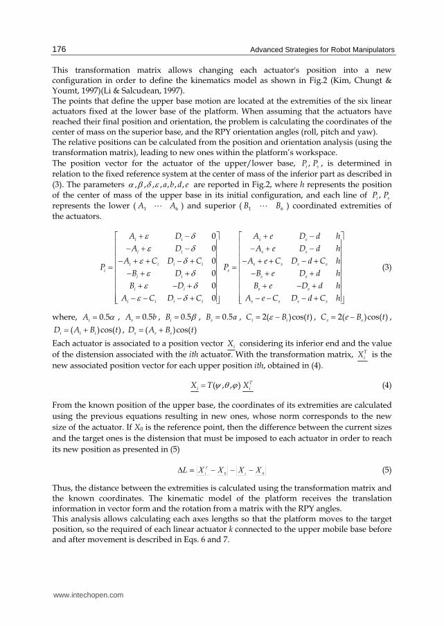
3.2 Kinematic model The Stewart Platform Manipulator changes its position and orientation as a function of its linear actuator’s length. Fig. 3 shows the corresponding geometric model viewed from the top, where the bottom base geometry is formed by the B1 to B6 points, and the upper one by A1 to A6 points.
Fig. 3. Stewart Platform geometric model
3.3 Inverse kinematics The inverse kinematics model of the manipulator expresses the joint linear motion as a position and orientation function due to the fixed coordinate system at the base of the platform (Wang, Gosselin & Cheng, 2002)(Zhang & Chen, 2007), as presented in Eq. 10:
( )xl=f (10)
Where, l=(l1,l2,l3,l4,l5,l6) is the linear position of the joints, x=(X, Y, Z, ψ, θ, φ) is the position vector of the platform, X,Y,Z the cartesian position and ψ, θ, φ represents the orientation of
www.intechopen.com
Advanced Strategies for Robot Manipulators
178
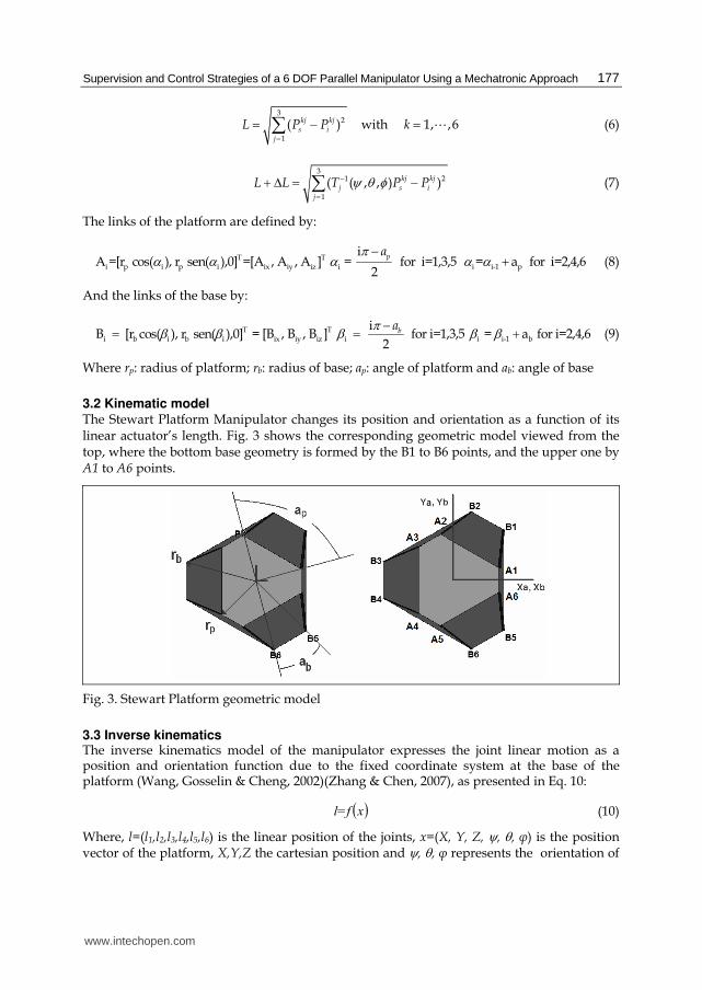
the platform. The reference systems are fixed to A(u,v,w) and B(x,y,z) at the base, as shown in Fig. 4.
Fig. 4. Vector representation of the manipulator.
The transformation for the mobile platform´s centroid to the base, is described by the position vector x and the rotation matrix BRA, where,
11 12 13
21 22 23
31 32 33
BA
r r r
R r r r
r r r
⎡ ⎤⎢ ⎥= ⎢ ⎥⎢ ⎥⎣ ⎦ (11)
The angular motions are expressed as Euler angle rotations in respect to x-axis, y-axis, and z-axis, i.e. roll, pitch and yaw, in sequence.
BA
c c c s s s c c s c s s c
R c c s s s c c s s c c s
s c c c c
ψ φ ψ φ θ ψ θ ψ φ θ ψ φ θψ φ ψ φ θ ψ θ ψ φ θ ψ θφ φ θ φ θ
− +⎡ ⎤⎢ ⎥= + −⎢ ⎥⎢ ⎥−⎣ ⎦ (12)
The vector-loop equation for the ith actuator of the manipulator is as follows:
Ai B i il R A x B= + − (13)
By substituting the terms for each actuator, (14) describes the platform motion in relation to its base.
( )( )( )( ) ( )( ) ( ) ( )2 2 2 2 2 2
11 12
21 22 31 23 31 23
2
2 2 2 2
i p b ix iy ix
ix iy iy ix iy iy ix iy ix iy
l = X + Y + Z + r + r + r A + r A X B
+ r A + r A Y B + r A + r A Y B + Z r A + r A XB + YB
−− − − (14)
3.4 Dynamics study The dynamic equations are derived for the Stewart Platform with a universal joint at the
base and a spherical joint at the top of each leg. For this study, it is assumed that there is no
rotation allowed on any leg about its own axis, so the kinematics and dynamics for each one
considers and calculates the constraining force over the spherical joint at its top.
Finally, the kinematics and dynamics of the platform are considered so the spherical joint
forces from all the six legs complete the dynamic equations.
The motion control can be implemented on every joint considering the movements of each actuator (Guo & Li, 2006). Considering the coupling effects and to solve the trajectory
www.intechopen.com
Supervision and Control Strategies of a 6 DOF Parallel Manipulator Using a Mechatronic Approach
179
problem, the dynamic control takes the inputs of the system so the drive of each joint moves its links to the target position with the required speed. The dynamic model of a 6-DOF platform can be calculated with the Euler-Lagrange formulation that expresses the generalized torque (Jaramillo et al, 2006)(Liu, Li and Li, 2000).The dynamic model is described by a set of differential equations called dynamic equations of motion as shown in (15).
1, ,6J L F L ii i i i i iτ = + + Γ =$$ $ A (15)
where ( )i tτ is the generalized torque vector, ( )iL t the generalized frame vector (linear
joints), ( )iJ t the inertial matrix, ( )iF t the non-linear forces (for example centrifugal) matrix,
iΓ the gravity force matrix.
3.5 Actuator model Each joint is composed of a motor, a transmission system and an encoder and by considering DC motor (Ollero, Boverie & Goodal, 2005), its three classic equations are presented in Eq. 16
d ( )d ( )( ) ( )
d d
2d ( ) d ( )( ) ( )
2 dd
ti t mu t L R i t Kmot mot Et t
t tm mT t J B K i tm eq eq Ttt
θ
θ θ= + +
= + = (16)
where ( )mT t is the torque, ( )m tθ the angular position of the motor axis, ( )i t the current,
,mot motL R respectively the inductance, resistance, eqJ , eqB the inertia, friction of the axis load
calculated on the motor side.
4. Control structure
A simulation environment allows implementing and testing advanced axis control
strategies, such as Predictive Control, which is a well known structure for providing
improved tracking performance. The purpose of the control structure is to obtain a model of
the system that predicts the future system's behaviour, calculates the minimization of a
quadratic cost function over a finite future horizon using future predicted errors. It also
elaborates a sequence of future control values; only the first value is applied both on the
system and the model, finally the repetition of the whole procedure at the next sampling
period happens accordingly to the preceding horizon strategy (Li & Salcudean, 1997)
(Nadimi, Bak & Izadi, 2006)(Remillard & Boukas, 2007)(Su et al, 2004).
4.1 Model The Controlled Autoregressive Integrated Moving Average Model (CARIMA) form is used
as numerical model for the system so the steady state error is cancelled due to a step input
or disturbance by introducing an integral term in the controller (Clarke, Mohtadi & Tuffs,
www.intechopen.com
Advanced Strategies for Robot Manipulators
180
1987). The predictive control law uses an external input-output representation form, given
by the polynomial relation:
1 1
1
( )( ) ( ) ( ) ( 1)
( )
kA q y k B q u k
q
ξ− −−= − + Δ (17)
where u is the control signal applied to the system, y the output of the system, Δ(q-1) =1 - q-1
the difference operator, A and B polynomials in the backward shift operator q-1, of
respective order na and nb, ξ an uncorrelated zero-mean white noise.
4.2 Predictive equation The predictive method requires the definition of an optimal j-step ahead predictor which is
able to anticipate the behaviour of the process in the future over a finite horizon. From the
input-output model, the polynomial predictor is designed under the following form:
1 1 1 1
free response forced response
ˆ( ) ( ) ( ) ( ) ( 1) ( ) ( 1) ( ) ( )j j j jy k j F q y k H q u k G q u k j J q k jξ− − − −+ = + Δ − + + Δ + − + +'*****(*****) '*******(*******)
(18)
where Fj, Gj, Hj and Jj, unknown polynomials, corresponding to the expression of the past
and of the future, are derived solving Diophantine equations, with unique solutions
controller (Clarke, Mohtadi & Tuffs, 1987).
4.3 Cost function The GPC strategy minimizes the weighted sum of the square predicted future errors and the
square control signal increments:
( )2
1
2 2
1
ˆ( ) ( ) ( 1)uNN
j N j
J y k j w k j u k jλ= =
= + − + + Δ + −∑ ∑ (19)
Assuming that 0)( =+Δ jtu for uj N≥ . Four tuning parameters are required: N1, the
minimum prediction horizon, N2 the maximum prediction horizon, Nu the control horizon
and λ the control-weighting factor.
4.4 Cost function minimization The optimal j-step ahead predictor (20) is rewritten in matrix form:
1 1ˆ ( ) ( ) 1q y t q u t− −= + + Δ −y Gu if ( ) ih ( )# (20)
ith:
1 1 1( ) ( ) ( )1 2
1 1 1( ) ( ) ( )1 2
q F q F qN N
q H q H qN N
⎡ ⎤− − − ′= ⎢ ⎥⎣ ⎦⎡ ⎤− − − ′= ⎢ ⎥⎣ ⎦
if
ih
A
A 1 2
( ) ( 1)
ˆ ˆ ˆ( ) ( ))
uu t u t N
y t N y t N
′= Δ Δ + −⎡ ⎤⎣ ⎦= + +⎡ ⎤⎣ ⎦
u
y
# A
A (21)
www.intechopen.com
Supervision and Control Strategies of a 6 DOF Parallel Manipulator Using a Mechatronic Approach
181
1 1
1 1
1 1
1 1
2 2 2
2 2 2
1
1 11
1 1u
N NN N
N NN N
N N NN N N N
g g
g g
g g g
−+ ++
− − +
⎡ ⎤⎢ ⎥⎢ ⎥= ⎢ ⎥⎢ ⎥⎢ ⎥⎣ ⎦G
A AA A
A A A AA
(22)
The future control sequence is then obtained by minimizing the criterion (23) (Clarke, Mohtadi and Tuffs, 1987):
1 1( ) ( ) ( ) ( 1)q y t q u t− −⎡ ⎤= − − Δ −⎢ ⎥⎣ ⎦u M w if ih# (23)
with:
'=M Q G , 2 1( 1)uN N N× − + ,1
' Nuλ −⎡ ⎤= +⎢ ⎥⎣ ⎦Q G G I , 1 2( ) ( )w t N w t N= + +⎡ ⎤⎣ ⎦w A (24)
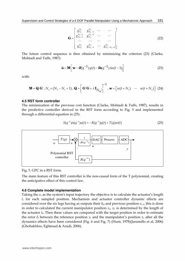
4.5 RST form controller The minimization of the previous cost function (Clarke, Mohtadi & Tuffs, 1987), results in
the predictive controller derived in the RST form according to Fig. 5 and implemented
through a differential equation in (25).
1 1 1( ) ( ) ( ) ( ) ( ) ( ) ( )S q q u t R q y t T q w t− − −Δ = − + (25)
+
-
w u
y
)( 1−qR
Polynomial RST
controller
)(qT DAC Process ADC)(
1
1−qSΔ
Fig. 5. GPC in a RST form.
The main feature of this RST controller is the non-causal form of the T polynomial, creating
the anticipative effect of this control law.
4.6 Complete model implementation Taking the xr as the system's input trajectory the objective is to calculate the actuator’s length
lr for each sampled position. Mechanism and actuator controller dynamic effects are
considered over the six legs having as outputs their δld and previous position xi-1, this is done
in order to calculated the current manipulator position xo, xf is determined by the length of
the actuator l0. Then these values are compared with the target position in order to estimate
the error δl between the reference position xr and the manipulator’s position xo after all the
dynamics effects have been considered (Fig. 6 and Fig. 7) (Hunt, 1978)(Jaramillo et al, 2006)
(Ghobakhloo, Eghtesad & Azadi, 2006).
www.intechopen.com
Advanced Strategies for Robot Manipulators
182
(b) Actuator model
(a) Global model
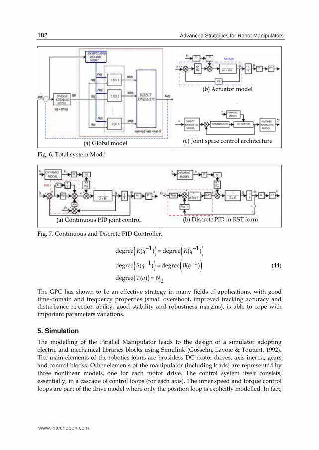
(c) Joint space control architecture
Fig. 6. Total system Model
(a) Continuous PID joint control
(b) Discrete PID in RST form
Fig. 7. Continuous and Discrete PID Controller.
( ) ( )( ) ( )( )
1 1degree ( ) degree ( )
1 1degree ( ) degree ( )
degree ( ) 2
R q R q
S q B q
T q N
− −=− −==
(44)
The GPC has shown to be an effective strategy in many fields of applications, with good time-domain and frequency properties (small overshoot, improved tracking accuracy and disturbance rejection ability, good stability and robustness margins), is able to cope with important parameters variations.
5. Simulation
The modelling of the Parallel Manipulator leads to the design of a simulator adopting
electric and mechanical libraries blocks using Simulink (Gosselin, Lavoie & Toutant, 1992).
The main elements of the robotics joints are brushless DC motor drives, axis inertia, gears
and control blocks. Other elements of the manipulator (including loads) are represented by
three nonlinear models, one for each motor drive. The control system itself consists,
essentially, in a cascade of control loops (for each axis). The inner speed and torque control
loops are part of the drive model where only the position loop is explicitly modelled. In fact,
www.intechopen.com
Supervision and Control Strategies of a 6 DOF Parallel Manipulator Using a Mechatronic Approach
183
the position control of the manipulator can be implemented through the control feedback of
each isolated joint (Cappel, 1967).
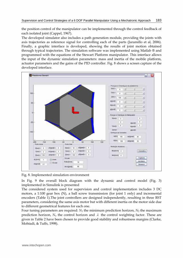
The developed simulator also includes a path generation module, providing the joints with axis trajectories as reference signal for controlling each of the parts (Jaramillo et al, 2006). Finally, a graphic interface is developed, showing the results of joint motion obtained through typical trajectories. The simulation software was implemented using Matlab ® and programmed with the equations of the Stewart Platform manipulator. This interface allows the input of the dynamic simulation parameters: mass and inertia of the mobile platform, actuator parameters and the gains of the PID controller. Fig. 8 shows a screen capture of the developed interface.
Fig. 8. Implemented simulation environment
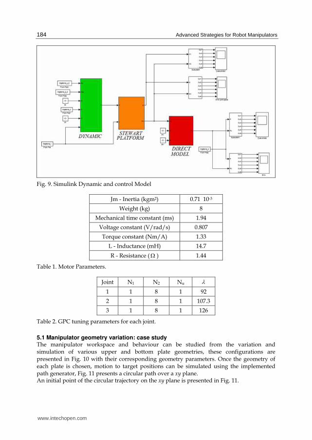
In Fig. 9 the overall block diagram with the dynamic and control model (Fig. 3) implemented in Simulink is presented The considered system used for supervision and control implementation includes 3 DC motors, a 1:100 gear box (N), a ball screw transmission (for joint 1 only) and incremental encoders (Table 1).The joint controllers are designed independently, resulting in three RST parameters, considering the same axis motor but with different inertia on the motor side due to different geometrical features for each one. Four tuning parameters are required: N1 the minimum prediction horizon, N2 the maximum
prediction horizon, Nu the control horizon and λ the control weighting factor. These are
given in Table 2 have been chosen to provide good stability and robustness margins (Clarke, Mohtadi, & Tuffs, 1998).
www.intechopen.com
Advanced Strategies for Robot Manipulators
184
Fig. 9. Simulink Dynamic and control Model
Jm - Inertia (kgm2) 0.71 10-3
Weight (kg) 8
Mechanical time constant (ms) 1.94
Voltage constant (V/rad/s) 0.807
Torque constant (Nm/A) 1.33
L - Inductance (mH) 14.7
R - Resistance (Ω ) 1.44
Table 1. Motor Parameters.
Joint N1 N2 Nu λ
1 1 8 1 92
2 1 8 1 107.3
3 1 8 1 126
Table 2. GPC tuning parameters for each joint.
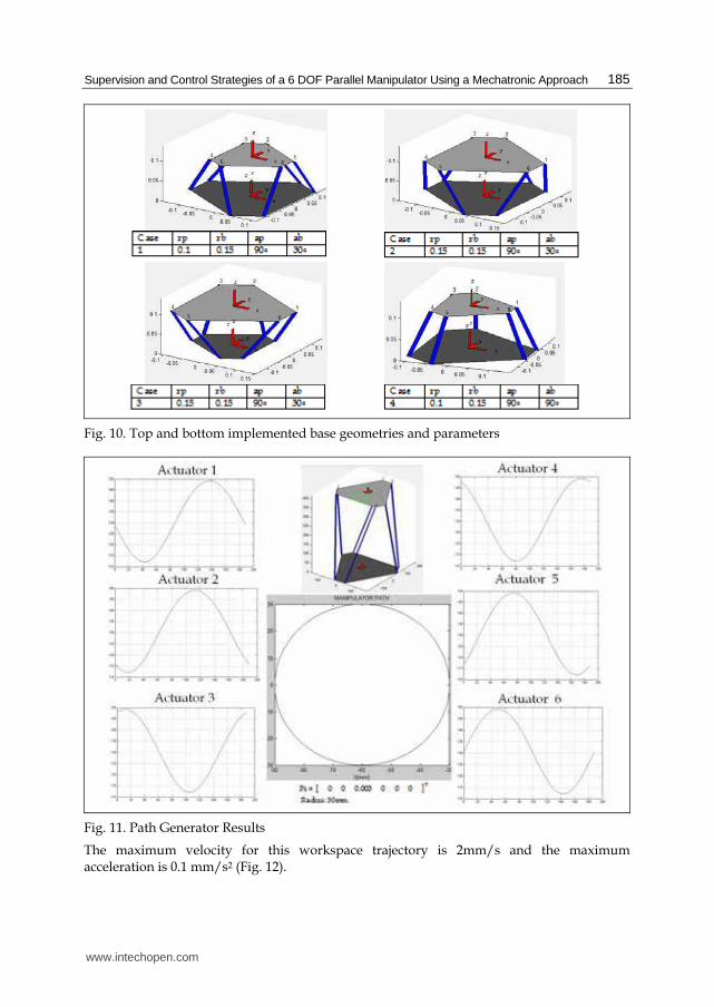
5.1 Manipulator geometry variation: case study The manipulator workspace and behaviour can be studied from the variation and simulation of various upper and bottom plate geometries, these configurations are presented in Fig. 10 with their corresponding geometry parameters. Once the geometry of each plate is chosen, motion to target positions can be simulated using the implemented path generator, Fig. 11 presents a circular path over a xy plane. An initial point of the circular trajectory on the xy plane is presented in Fig. 11.
www.intechopen.com
Supervision and Control Strategies of a 6 DOF Parallel Manipulator Using a Mechatronic Approach
185
Fig. 10. Top and bottom implemented base geometries and parameters
Fig. 11. Path Generator Results
The maximum velocity for this workspace trajectory is 2mm/s and the maximum acceleration is 0.1 mm/s2 (Fig. 12).
www.intechopen.com
Advanced Strategies for Robot Manipulators
186
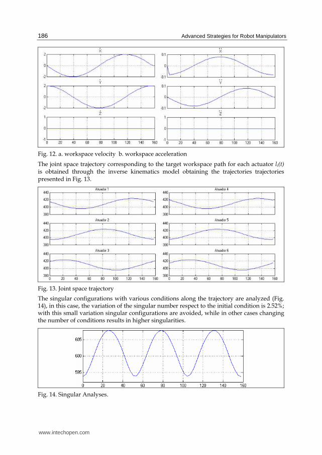
Fig. 12. a. workspace velocity b. workspace acceleration
The joint space trajectory corresponding to the target workspace path for each actuator li(t) is obtained through the inverse kinematics model obtaining the trajectories trajectories presented in Fig. 13.
Fig. 13. Joint space trajectory
The singular configurations with various conditions along the trajectory are analyzed (Fig. 14), in this case, the variation of the singular number respect to the initial condition is 2.52%; with this small variation singular configurations are avoided, while in other cases changing the number of conditions results in higher singularities.
Fig. 14. Singular Analyses.
www.intechopen.com
Supervision and Control Strategies of a 6 DOF Parallel Manipulator Using a Mechatronic Approach
187
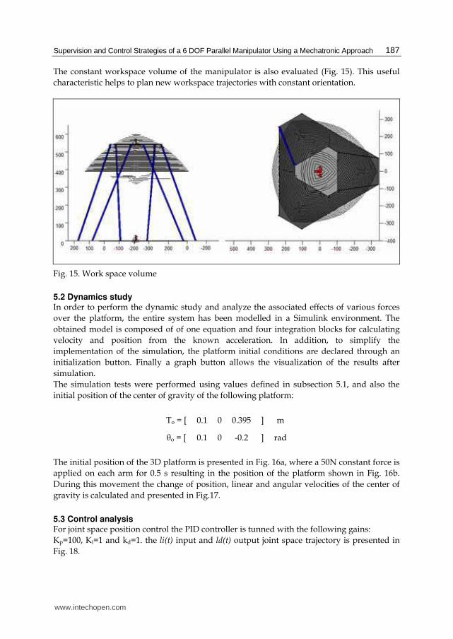
The constant workspace volume of the manipulator is also evaluated (Fig. 15). This useful
characteristic helps to plan new workspace trajectories with constant orientation.
Fig. 15. Work space volume
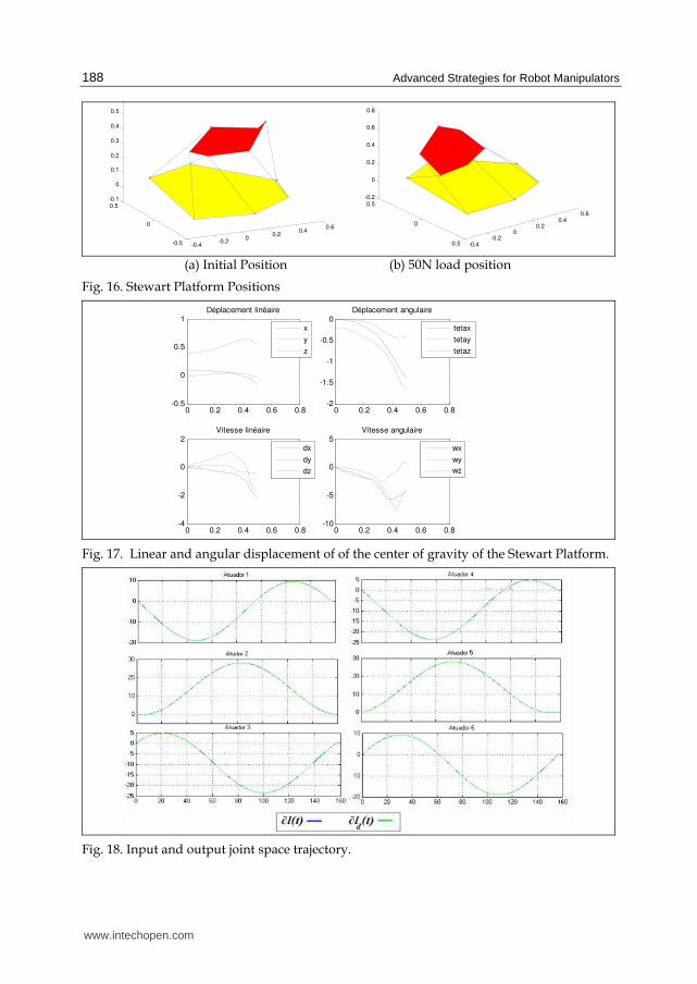
5.2 Dynamics study In order to perform the dynamic study and analyze the associated effects of various forces
over the platform, the entire system has been modelled in a Simulink environment. The
obtained model is composed of of one equation and four integration blocks for calculating
velocity and position from the known acceleration. In addition, to simplify the
implementation of the simulation, the platform initial conditions are declared through an
initialization button. Finally a graph button allows the visualization of the results after
simulation.
The simulation tests were performed using values defined in subsection 5.1, and also the
initial position of the center of gravity of the following platform:
To = [ 0.1 0 0.395 ] m
θo = [ 0.1 0 -0.2 ] rad
The initial position of the 3D platform is presented in Fig. 16a, where a 50N constant force is
applied on each arm for 0.5 s resulting in the position of the platform shown in Fig. 16b.
During this movement the change of position, linear and angular velocities of the center of
gravity is calculated and presented in Fig.17.
5.3 Control analysis For joint space position control the PID controller is tunned with the following gains:
Kp=100, Ki=1 and kd=1. the li(t) input and ld(t) output joint space trajectory is presented in
Fig. 18.
www.intechopen.com
Advanced Strategies for Robot Manipulators
188
-0.4-0.2
00.2
0.40.6
-0.5
0
0.5-0.1
0
0.1
0.2
0.3
0.4
0.5
-0.4
-0.20
0.20.4
0.6
-0.5
0
0.5-0.2
0
0.2
0.4
0.6
0.8
(a) Initial Position (b) 50N load position
Fig. 16. Stewart Platform Positions
0 0.2 0.4 0.6 0.8-0.5
0
0.5
1Déplacement linéaire
0 0.2 0.4 0.6 0.8-2
-1.5
-1
-0.5
0Déplacement angulaire
0 0.2 0.4 0.6 0.8-4
-2
0
2Vitesse linéaire
0 0.2 0.4 0.6 0.8-10
-5
0
5Vitesse angulaire
wx
wy
wz
tetax
tetay
tetaz
x
y
z
dx
dy
dz
Fig. 17. Linear and angular displacement of of the center of gravity of the Stewart Platform.
Fig. 18. Input and output joint space trajectory.
www.intechopen.com
Supervision and Control Strategies of a 6 DOF Parallel Manipulator Using a Mechatronic Approach
189
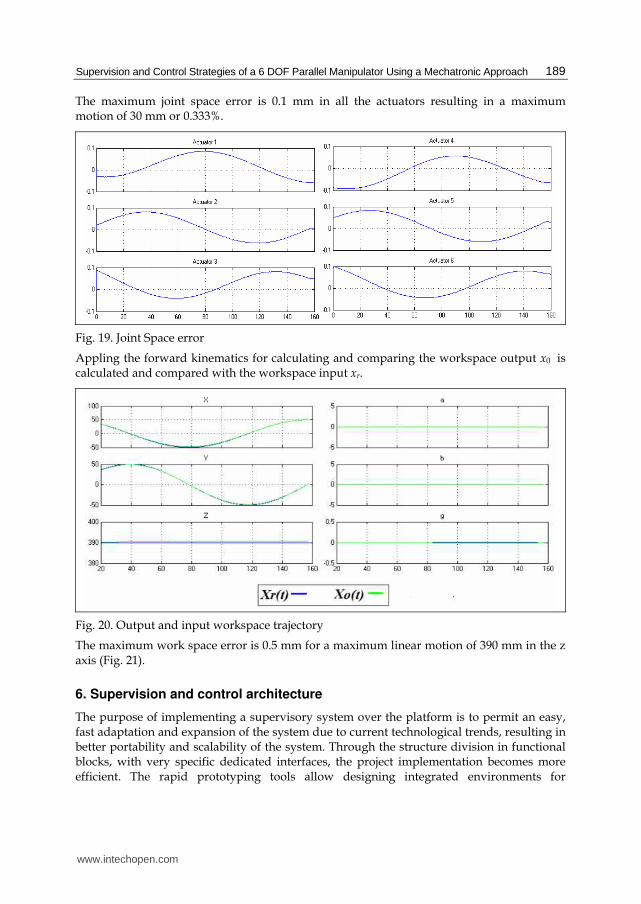
The maximum joint space error is 0.1 mm in all the actuators resulting in a maximum motion of 30 mm or 0.333%.
Fig. 19. Joint Space error
Appling the forward kinematics for calculating and comparing the workspace output x0 is calculated and compared with the workspace input xr.
Fig. 20. Output and input workspace trajectory
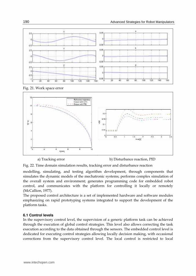
The maximum work space error is 0.5 mm for a maximum linear motion of 390 mm in the z axis (Fig. 21).
6. Supervision and control architecture
The purpose of implementing a supervisory system over the platform is to permit an easy, fast adaptation and expansion of the system due to current technological trends, resulting in better portability and scalability of the system. Through the structure division in functional blocks, with very specific dedicated interfaces, the project implementation becomes more efficient. The rapid prototyping tools allow designing integrated environments for
www.intechopen.com
Advanced Strategies for Robot Manipulators
190
Fig. 21. Work space error
a) Tracking error b) Disturbance reaction, PID
Fig. 22. Time domain simulation results, tracking error and disturbance reaction
modelling, simulating, and testing algorithm development, through components that
simulates the dynamic models of the mechatronic systems; performs complex simulation of
the overall system and environment; generates programming code for embedded robot
control, and communicates with the platform for controlling it locally or remotely
(McCallion, 1977).
The proposed control architecture is a set of implemented hardware and software modules
emphasizing on rapid prototyping systems integrated to support the development of the
platform tasks.
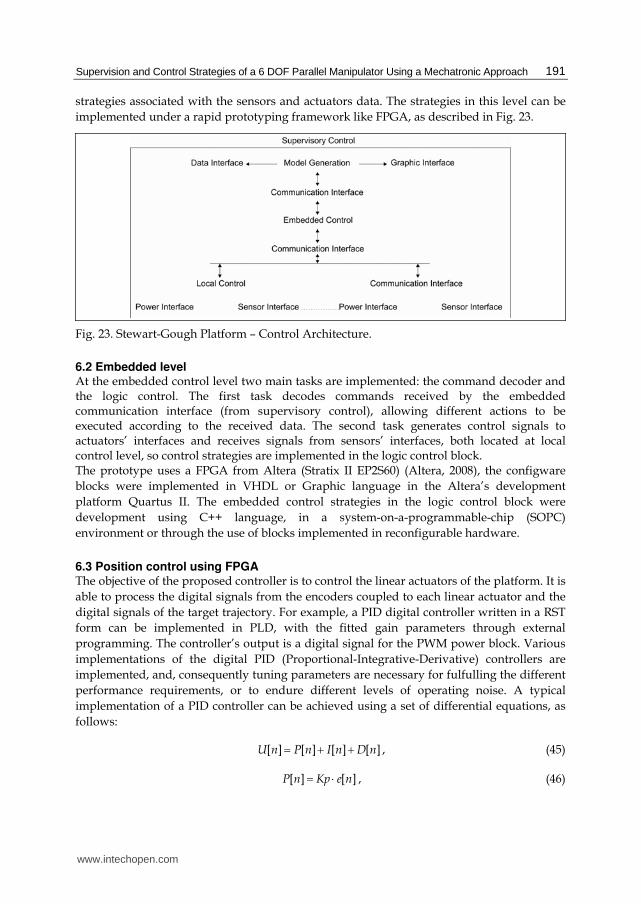
6.1 Control levels In the supervisory control level, the supervision of a generic platform task can be achieved
through the execution of global control strategies. This level also allows correcting the task
execution according to the data obtained through the sensors. The embedded control level is
dedicated for executing control strategies allowing locally decision making, with occasional
corrections from the supervisory control level. The local control is restricted to local
www.intechopen.com
Supervision and Control Strategies of a 6 DOF Parallel Manipulator Using a Mechatronic Approach
191
strategies associated with the sensors and actuators data. The strategies in this level can be
implemented under a rapid prototyping framework like FPGA, as described in Fig. 23.
Fig. 23. Stewart-Gough Platform – Control Architecture.
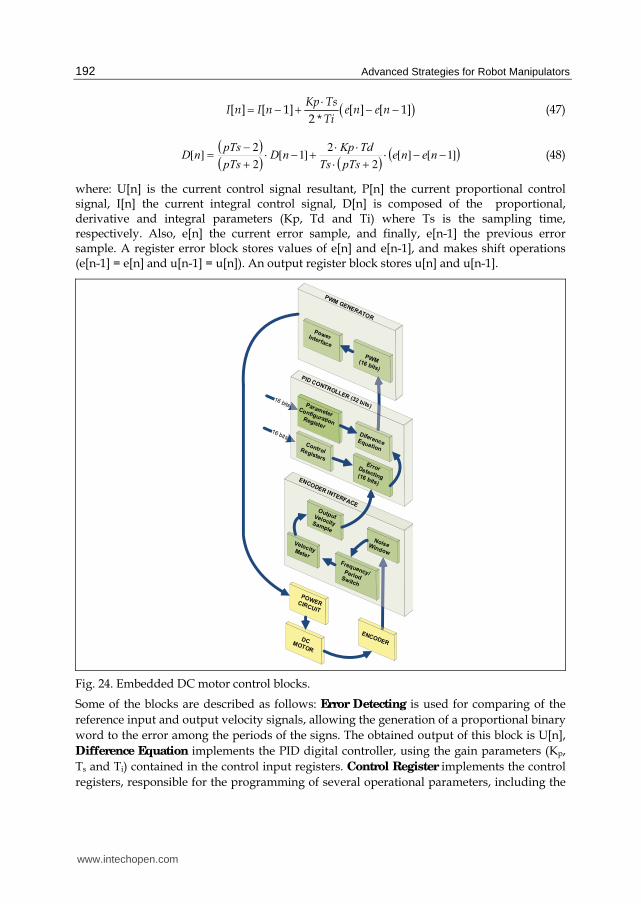
6.2 Embedded level At the embedded control level two main tasks are implemented: the command decoder and the logic control. The first task decodes commands received by the embedded communication interface (from supervisory control), allowing different actions to be executed according to the received data. The second task generates control signals to actuators’ interfaces and receives signals from sensors’ interfaces, both located at local control level, so control strategies are implemented in the logic control block. The prototype uses a FPGA from Altera (Stratix II EP2S60) (Altera, 2008), the configware
blocks were implemented in VHDL or Graphic language in the Altera’s development
platform Quartus II. The embedded control strategies in the logic control block were
development using C++ language, in a system-on-a-programmable-chip (SOPC)
environment or through the use of blocks implemented in reconfigurable hardware.
6.3 Position control using FPGA The objective of the proposed controller is to control the linear actuators of the platform. It is
able to process the digital signals from the encoders coupled to each linear actuator and the
digital signals of the target trajectory. For example, a PID digital controller written in a RST
form can be implemented in PLD, with the fitted gain parameters through external
programming. The controller’s output is a digital signal for the PWM power block. Various
implementations of the digital PID (Proportional-Integrative-Derivative) controllers are
implemented, and, consequently tuning parameters are necessary for fulfulling the different
performance requirements, or to endure different levels of operating noise. A typical
implementation of a PID controller can be achieved using a set of differential equations, as
follows:
[ ] [ ] [ ] [ ]U n P n I n D n= + + , (45)
[ ] [ ]P n Kp e n= ⋅ , (46)
www.intechopen.com
Advanced Strategies for Robot Manipulators
192
( )[ ] [ 1] [ ] [ 1]2 *
Kp TsI n I n e n e n
Ti
⋅= − + − − (47)
( )( ) ( ) ( )]1[][
2
2]1[
2
2][ −−⋅+⋅
⋅⋅+−⋅+−= nene
pTsTs
TdKpnD
pTs
pTsnD (48)
where: U[n] is the current control signal resultant, P[n] the current proportional control signal, I[n] the current integral control signal, D[n] is composed of the proportional, derivative and integral parameters (Kp, Td and Ti) where Ts is the sampling time, respectively. Also, e[n] the current error sample, and finally, e[n-1] the previous error sample. A register error block stores values of e[n] and e[n-1], and makes shift operations (e[n-1] = e[n] and u[n-1] = u[n]). An output register block stores u[n] and u[n-1].
16 bits
16 bits
PID CONTROLLER (32 bits)
DCMOTOR
Parameter Configuration
Register
ErrorDetecting(16 bits)
DiferenceEquation
OutputVelocitySample
ENCODER
Control Registers
NoiseWindow
Frequency/PeriodSwitch
VelocityMeter
POWERCIRCUIT
Power Interface
PWM(16 bits)
PWM GENERATOR
ENCODER INTERFACE
Fig. 24. Embedded DC motor control blocks.
Some of the blocks are described as follows: Error Detecting is used for comparing of the
reference input and output velocity signals, allowing the generation of a proportional binary
word to the error among the periods of the signs. The obtained output of this block is U[n],
Difference Equation implements the PID digital controller, using the gain parameters (Kp,
Ts and Ti) contained in the control input registers. Control Register implements the control
registers, responsible for the programming of several operational parameters, including the
www.intechopen.com
Supervision and Control Strategies of a 6 DOF Parallel Manipulator Using a Mechatronic Approach
193
gain parameters. PWM and Power Interface converts the binary word supplied by PID
controller in a pattern of digital signs to control the PWM potency block.
The considered reconfiguration in the interface and logical block design eases testing,
implementation and future updating, due to this, the development of systems based on
reconfigurable computing present well-suited features for developing this kind of problem.
The synchronized control of the actuator system can be easily achieved through the same PLD.
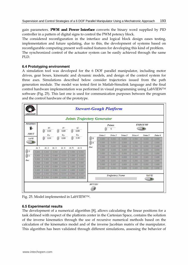
6.4 Prototyping environment A simulation tool was developed for the 6 DOF parallel manipulator, including motor
drives, gear boxes, kinematic and dynamic models, and design of the control system for
three axes. Simulations described below consider trajectories issued from the path
generation module. The model was tested first in Matlab-Simulink language and the final
control hardware implementation was performed in visual programming using LabVIEWTM
software (Fig. 25). This last one is used for communication purposes between the program
and the control hardware of the prototype.
Fig. 25. Model implemented in LabVIEWTM.
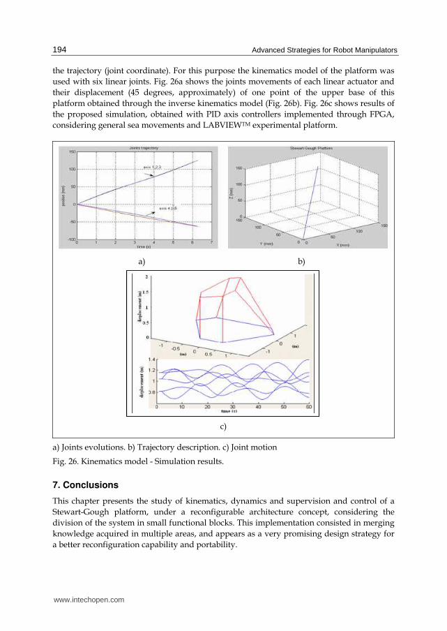
6.5 Experimental results The development of a numerical algorithm [8], allows calculating the linear positions for a
task defined with respect of the platform center in the Cartesian Space, contains the solution
of the inverse kinematics through the use of recursive numerical methods based on the
calculation of the kinematics model and of the inverse Jacobian matrix of the manipulator.
This algorithm has been validated through different simulations, assessing the behavior of
www.intechopen.com
Advanced Strategies for Robot Manipulators
194
the trajectory (joint coordinate). For this purpose the kinematics model of the platform was
used with six linear joints. Fig. 26a shows the joints movements of each linear actuator and
their displacement (45 degrees, approximately) of one point of the upper base of this
platform obtained through the inverse kinematics model (Fig. 26b). Fig. 26c shows results of
the proposed simulation, obtained with PID axis controllers implemented through FPGA,
considering general sea movements and LABVIEWTM experimental platform.
a) b)
c)
a) Joints evolutions. b) Trajectory description. c) Joint motion
Fig. 26. Kinematics model - Simulation results.
7. Conclusions
This chapter presents the study of kinematics, dynamics and supervision and control of a
Stewart-Gough platform, under a reconfigurable architecture concept, considering the
division of the system in small functional blocks. This implementation consisted in merging
knowledge acquired in multiple areas, and appears as a very promising design strategy for
a better reconfiguration capability and portability.
www.intechopen.com
Supervision and Control Strategies of a 6 DOF Parallel Manipulator Using a Mechatronic Approach
195
This platform also becomes a powerful benchmark for many research activities, such as the validation of controllers and supervision strategies, model generation and data transmission protocols, among others. For example, the implementation of predictive controllers on this prototype may enable the test of this advanced control strategy under severe conditions of use. To simplify tests, implementation and future modifications, the use of rapid prototyping functions in the implementation of the interfaces and other logical blocks is emphasized in the proposed prototype. The control block, for example, can benefit of the characteristics of low consumption, high-speed operations, integration capacity, flexibility and simple programming. Some promising aspects of this architecture are:
• Flexibility, as there is a large variety of possible configurations in the implementation of solutions for several problems,
• It is a powerful tool for prototype design, allowing simple solution to control the several sensors and actuators usually present in this kind of projects,
• Possibility of modification of control strategies during operation of the platform,
• The open architecture of this platform enables the use for educational and researches activities.
8. References
Altera Corporation. http://www.altera.com, 2008. Bessala, J.; Philippe, B. & Ben Ouezdou, F. (1996). Analytical Study of Stewart Platforms
Workspaces. Proceedings of the 1996 IEEE International Conference on Robotics and Automation. pp. 3179-3184.
Cappel, K. (1967). Motion simulator. Patent No. 3,295,224 , US Patent No. 3,295,224. Clarke D. W., Mohtadi C., Tuffs P.S. (1987) Generalized Predictive Control. Part I. The Basic
Algorithm. Part II. Extensions and Interpretation, Automatica. Vol.23(2). pp. 137-160. Dasgupta, B. & Mruthyunjaya, T. (1998). Newton-Euler formulation for the inverse
dynamics of the Stewart platform manipulator. Mechanism and Machine Theory Vol. 33(8). pp. 135-1152.
Fasse, E. & Gosselin, C. (1998). On the spatial impedance control of Gough-Stewart platforms. IEEE International Conference on Robotics and Automation. pp. 1749-1754.
Ghobakhloo, A.; Eghtesad, M. & Azadi, M. (2006). Position Control of a Stewart-Gough Platform using Inverse dynamics Method with full dynamics. International Workshop on Advanced Motion Control, AMC. Vol. 1. pp. 50-55.
Gosselin C.; Lavoie, E. & Toutant, P. (1992). An efficient algorithm for the graphical representation of the threedimensional workspace of parallel manipulators. Proceeding of the 22nd ASME Mechanisms Conference. pp. 323-328.
Gosselin, C. M.; Perreault, L. & Vaillancourt, C. (1999). Simulation and Computer-Aided Kinematic Desing of Tree-Degree-of-Freedom Spherical Parallel Manipulators. Jornal of Robotic Systems. Vol.12(12). pp. 857-869.
Gough, V.E. e Whitehall, S. (1962). Universal tyre test machine. Proceedings of the FISITA Ninth International Technical Congress. pp. 117-137.
Guo, H. B. & Li, H. R. (2006). Dynamic analysis and simulation of a six degree of freedom Stewart platform manipulator. Proceedings of the Institution of Mechanical Engineers. Part C, Journal of Mechanical Engineering Science. Vol. 220(1). pp. 61-72.
www.intechopen.com
Advanced Strategies for Robot Manipulators
196
Jaramillo-Botero, A.; Matta-Gomez, A.; Correa-Caicedo, J. F. & Perea-Castro, W. (2006). Robotics Modeling and Simulation Platform. Robotics & Automation Magazine. IEEE Vol. 13. pp. 62-73.
Karger, A. (2003) Architecture singular planar parallel manipulators. Mechanism and Machine Theory, Vol. 38, pp. 1149-1164.
Kim, D. I.; Chungt, W. K. & Youmt, Y. (1997). Geometrical Approach for the Workspace of 6-DOF Parallel Manipulators. Proceedings of the 1997 IEEE lnternational Conference on Robotics and Automation. pp. 2986-299 1.
Li, D. & Salcudean, S. E. (1997). Modeling, Simulation, and Control of a Hydraulic Stewart Platform. Proceedings of the 1997 JEEE International Conference on Robotics and Automation. Vol. 4. pp. 3360-3366.
Liu, M.; Li, C. & Li, C. (2000). Dynamics Analysis of the Gough–Stewart Platform Manipulator. IEEE Transactions on Robotics and Automation. Vol.16(1). pp. 94-98.
MacCallion, H. e. D. P. (1979). The analisys of six degrees of freedom work and station for mechanized assembly. 5th Congress on theory of machines and mechanisms. pp. 616.
Nadimi, E. S.; Bak, T. & Izadi-Zamanabadi, R. (2006). Model Predictive Controller Combined with LQG Controller and Velocity Feedback to Control the Stewart Platform. Advanced Motion Control, 2006. 9th IEEE International Workshop Vol. 1(0.1109/AMC.2006.1631630). pp. 44-49.
Ollero, S. Boverie, R. Goodal. Mechatronics. (2005). Robotics and Components for Automation and Control, Annual Reviews in Control IFAC Journal. Vol. 25. pp. 203–228.
Remillard, V. & Boukas, E. (2007). Gough-Stewart Platforrn Control: A Fuzzy control approach. Annual meeting of the North American Fuzzy Information Processing Society. Vol. 1. pp. 108 - 113.
Stewart, D. (1965). A platform with six degrees of freedom. Proceedings of the IMechE. 180(15). pp. 371-385.
Su, Y. X.; Duan, B. Y.; Zheng, C. H.; Zhang, Y. F.; Chen, G. D. & Mi, J. W. (2004), 'Disturbance-Rejection High-Precision Motion Control of a Stewart Platform'(3)'IEEE TRANSACTIONS ON CONTROL SYSTEMS TECHNOLOGY'.
Sugahara, Y.; Ohta, A.; Hashimoto, K.; Sunazuka, H.; Kawase, M.; Tanaka, C.; Lim, H. & Takanishi, A. (2005), 'Walking Up and Down Stairs Carrying a Human by a Biped Locomotor with Parallel Mechanism', Intelligent Robots and Systems International Conference on Volume, 1489 - 1494.
Wang, J.; Gosselin, C. & Cheng, L. (2002). Modeling and simulation of robotic systems with closed kinematic chains using the virtual spring approach. Multibody System Dynamics. Vol. 7(2). pp. 145-170.
Wendlandt, J. M. & Sastry, S. S. (1994). Design and Control of a Simplified Stewart Platform for Endoscopy. Proceedings of the 33rd conferenceon Decision and Control. Vol.1. pp. 357-362.
Zhang, Z. & Chen, T. (2007). Modeling and Movement Simulation of a Manipulator of 6-DOF Based on Stewart Platform with Pro/E. 10th IEEE International Conference on Computer-Aided Design and Computer Graphics. pp. 533 - 536.
www.intechopen.com
Advanced Strategies for Robot ManipulatorsEdited by S. Ehsan Shafiei
ISBN 978-953-307-099-5Hard cover, 428 pagesPublisher SciyoPublished online 12, August, 2010Published in print edition August, 2010
InTech EuropeUniversity Campus STeP Ri Slavka Krautzeka 83/A 51000 Rijeka, Croatia Phone: +385 (51) 770 447 Fax: +385 (51) 686 166www.intechopen.com
InTech ChinaUnit 405, Office Block, Hotel Equatorial Shanghai No.65, Yan An Road (West), Shanghai, 200040, China
Phone: +86-21-62489820 Fax: +86-21-62489821
Amongst the robotic systems, robot manipulators have proven themselves to be of increasing importance andare widely adopted to substitute for human in repetitive and/or hazardous tasks. Modern manipulators aredesigned complicatedly and need to do more precise, crucial and critical tasks. So, the simple traditionalcontrol methods cannot be efficient, and advanced control strategies with considering special constraints areneeded to establish. In spite of the fact that groundbreaking researches have been carried out in this realmuntil now, there are still many novel aspects which have to be explored.
How to referenceIn order to correctly reference this scholarly work, feel free to copy and paste the following:
Joao Mauricio Rosario, Didier Dumur, Alvaro Joffre Uribe Quevedo, Mariana Moretti and Fabian Lara (2010).Supervision and Control Strategies of a 6-DOF Parallel Manipulator Using a Mechatronic Approach, AdvancedStrategies for Robot Manipulators, S. Ehsan Shafiei (Ed.), ISBN: 978-953-307-099-5, InTech, Available from:http://www.intechopen.com/books/advanced-strategies-for-robot-manipulators/supervision-and-control-strategies-of-a-6-dof-parallel-manipulator-using-a-mechatronic-approach