Embed Size (px)
Citation preview

IAGT -October 15, 2007 1
Supersonic Ejector for Capturing Dry-Gas Seal Vent Gases
Hasan Imran US EPA Natural Gas STAR 14th Annual Senior Advisor, Climate Change Conference, Houston, Texas October 23, 2007

IAGT -October 15, 2007 2
Outline
1. Motivation and Challenges.
2. Why Supersonic Ejector.
3. Development of the Device.
4. Results of Testing of Two-Stage System.
5. Implementation at Compressor Station.
6. Conclusions.

IAGT -October 15, 2007 3
Process Side
Ambient Side
Clean Buffer Gas
Inert Buffer GasLeakage
Inert Buffer Gas
Typical Primary and Secondary Dry-Seal

IAGT -October 15, 2007 4
Primary Seal Leakage Rate
10-3 Kg/s
1.4
1.1
0.75
0.5
0.25
0 0 30
Shaft (mm)
250
200
150
100
50
60 90 120
Pressure-bar

IAGT -October 15, 2007 5
Ref: Thomas Robinson (TransCanada)
Why Capture Dry Gas Seal Vent?
Seal gas leakage 2.0-8.0 m3/hr ~average 5.0 m3/hr
1.55 MMScf/y # of TransCanada units 348 x 348 @ 50% utilization 269 MMScf/y Tonnes of natural gas 0.0440 lbs/cf
5,369 tonnes conversion to CO2-E 21 CO2-E 113 ktonnes/year
CO2 Emissions trading $15 per tonne of CO2-E Gas value $6 per MCF CO2-E value $1,691,237 Value of Gas $1,614,216 Total $3,305,453 Annual saving per unit: $9,498

IAGT -October 15, 2007 6
Concept of Ejector
Motive Gas
Suction Gas
Discharge Gas

IAGT -October 15, 2007 7
Why Ejector?
� Motive gas is available (fuel gas upstream of regulator).
� Discharge gas from the Ejector can be burned in the GG.
� Auxiliary boilers are not always employed in compressor station, and typically operate intermittently (on/off).
� Some stations do not have boilers (warm climate regions).
� No moving parts.
� Low cost.

IAGT -October 15, 2007 8
Why Supersonic Ejector?
� Low suction pressure 300-550 kPa-a.
� Hence high expansion ratio of motive/suction pressure (~ 14).
� Discharge pressure 2500–3400 kPa-a.
� Hence compression ratio up to 8.
� Low suction flow (5-15 m3/hr).

IAGT -October 15, 2007 9
Development of the SSE
� Two-stage supersonic ejectors:
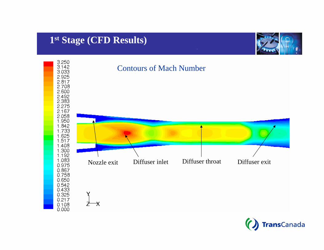
¾ The first stage is highly supersonic (nozzle exit Mach number ≈ 2.54),
¾ The second stage is moderately supersonic (nozzle exit Mach number ≈ 1.72).
� Extensive testing to arrive at optimum design.
� Final configuration gave
¾ expansion pressure ratio (motive/suction) of the order of 14.0 ¾ compression pressure ratio (discharge/suction) of around 8.1

IAGT -October 15, 2007 10
1st Stage Design
Nozzle Diameter mm 1.6 Nozzle Exit mm 2.8 Half Angle deg 1
Diffuser Inlet Diamter mm 4 Half Angle deg 4.7 Diffuser Throat Diameter mm 3.5 Diffuser Throat Length mm 8 Diffuser Exit Diameter mm 18 Diffuser Exit Half Angle deg 5
IAGT -October 15, 2007 11
1st Stage (CFD Results)
Contours of Mach Number
Nozzle exit Diffuser inlet Diffuser throat Diffuser exit
IAGT -October 15, 2007 12
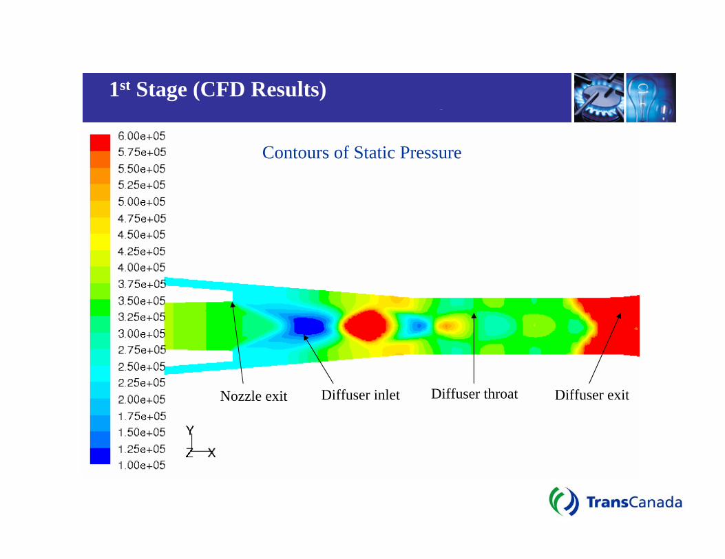
1st Stage (CFD Results)
Contours of Static Pressure
Nozzle exit Diffuser inlet Diffuser throat Diffuser exit

IAGT -October 15, 2007 13
m P T
P
P
P
T m
R
R R
Bench Testing at Compressor Station in Alberta
Expa
nsio
n R
atio
(P1/
P2)
Effic
ienc
y
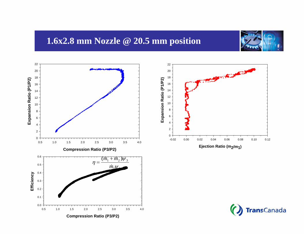
1.6x2.8 mm Nozzle @ 20.5 mm position
22 22
20 20
18
16
14
12
10
8
6
Expa
nsio
n R
atio
(P1/
P2) 18
16
14
12
10
8
6
44
2 2
0 0 -0.02 0.00 0.02 0.04 0.06 0.08 0.10 0.12
0.5 1.0 1.5 2.0 2.5 3.0 3.5 4.0
Compression Ratio (P3/P2) Ejection Ratio (m2/m1)
0.6 (m& 1 + m& 2 )ψ 3η = 0.5 m& 1ψ 1 0.4
0.3
0.2
0.1
0.0 0.5 1.0 1.5 2.0 2.5 3.0 3.5 4.0 14IAGT -October 15, 2007
Compression Ratio (P3/P2)

IAGT -October 15, 2007 15
Implementation
P&ID for Supersonic Gas Ejector Skid
Atmosphere
(7) (8) (9)
(N1)
(5)
(Fisher 310)
(2)
(3)
(4)
M
M
Atmosphere
Liquid & Particles filter
Ejector Skid
Fuel Gas Heater
Fuel Line (suction)
Compressor discharge (outside unit valve)
Primary Seal Leakage
700 kPag 700 kPag
½ T
½ T
1”
1” 2”
(6)
Comp. Suction (yard)
(1) Insulated
Insulated
(N2)
2” 1”
1.5”
1.5”
M
1”¾”
500 kPag 500 kPag
½”½”
Fuel gas to Engine

IAGT -October 15, 2007 16
2nd Stage Ejector Nozzles and Internals

IAGT -October 15, 2007 17
Test bench at Didsbury Compressor Station

IAGT -October 15, 2007 18
Dis
char
ge P
ress
ure
- kPa
(abs
)Test Results of the Two-Stage SSE System
3500
3400
3300
3200P1=4600 kPa
P1=5000 kPa 3100 P1=5500 kPa
3000
2900
0 1 2 3 4 5 6
Suction Flow - kg/hr

IAGT -October 15, 2007 19
P1=4600 kPa p1 =5000 kPa P1=5500 kPa
Test Results of the Two-Stage SSE SystemIn
term
edia
te P
ress
ure
(P3)
- kP
a (a
bs)
1600
1500
1400
1300
1200
1100
1000 0 1 2 3 4 5 6
Suction Flow - kg/hr

IAGT -October 15, 2007 20
Fuel Regulator (Fisher 310)
1200 kPa-a
3400 kPa-a
5000 kPa-a
6000 kPa-a
(P1)
(Pout)
(P3)
(Pin)Fuel Gas Line
P&ID Schematic of the 2-stage Ejector system
500 kPa-a (Leakage from Dry-Gas Seal)
(P2)

IAGT -October 15, 2007 21
Implementation

IAGT -October 15, 2007 22
Implementation
Fuel Gas System to Gas Turbine
Ejector Skid

IAGT -October 15, 2007 23
Project Team After Installation
TransCanada Compressor Station in Alberta

IAGT -October 15, 2007 24
Implementation
Gas-Gas Ejector Skid
First Stage
2nd Stage
Filter

IAGT -October 15, 2007 25
Operating Data
Field Test data collected from Pilot Project
Location # (Refer to Fig. 11) P (kPa-a) T (oC)
Mass Flow (kg/s)
Mass Flow (kg/hr)
1 5090 35.9 0.01770 63.720 DE Seal 506 10.0 0.001607 5.785
NDE Seal 512 10.0 0.001607 5.785 Total Seal Leakage 509 10.0 0.003214 11.570
N1 509 -113.0 0.01770 63.720 2 509 10.0 0.00286 10.285
Vent to Amb 509 10.0 0.00036 1.285 3 1190 12.7 0.021 74.005 4 5990 35.0 0.463 1668.240
N2 1190 -68.0 0.463 1668.240 5 2990 8.2 0.484 1742.245 6 5140 10.0 1.177 4237.500 7 5090 35.9 0.693 2495.255 8 2900 23.0 0.693 2495.255 9 2690 18.4 1.177 4237.500
Collected After Successful Commissioning of the Supersonic Ejector (Data Collected on June 23, 2007).

IAGT -October 15, 2007 26
Operating Data
Continued – Filed Test Data
Location # (Refer to Fig. 11)
P (kPa-a) T (oC) Mass Flow
(kg/s) Mass Flow
(kg/hr)
1 5800 35.9 0.02017 72.612 DE Seal 512 10.0 0.00214 7.704
NDE Seal 517 10.0 0.001696 6.106 Total Seal Leakage 515 10.0 0.003836 13.810
N1 515 -113.0 0.02017 72.612 2 515 10.0 0.00250 9.000
Vent to Amb 515 10.0 0.00134 4.810 3 1400 12.7 0.023 81.612 4 6540 35.0 0.506 1820.880
N2 1400 -68.0 0.506 1820.880 5 3160 8.2 0.528 1902.492 6 5850 10.0 1.177 4237.500 7 5800 35.9 0.649 2335.008 8 3100 23.0 0.649 2335.008 9 2690 18.4 1.177 4237.500
Collected After Successful Commissioning of the Supersonic Ejector (Data Collected on July 20, 2007).

IAGT -October 15, 2007 27
Benefits
Ejector 2nd stage motive flow 0.4634 kg/s Motive gas extra power needed 9,300 W Motive gas turbine extra fuel needed 31,000 W Fuel heating value 39 MJ/m3 Fuel heating value 52,000,000 J/kg Fuel gas burned 0.000596154 kg/s GHG CO2 from above burning 0.00155 kg/s GHG CO2 from above burning 48.8808 tonnes/year
Captured Dry-seal vent gas 9 kg/hr Captured Dry-seal vent gas 0.0025 kg/s Heat Energy Equivalent 130,000 W GHG CO2-E of the captured gas 0.0525 kg/s GHG CO2-E of the captured gas 1,656 tonnes/year
Net Heat Energy Saving 99,000 W Net GHG CO2-E 1,607 tonnes/year
Net Savings

IAGT -October 15, 2007 28
Conclusions
¾ It is possible to achieve a very high expansion ratio (14-18 20 times) with a supersonic nozzle. The challenge is always in the recompression of the expanded gas through a supersonic diffuser.
¾ For the application of a supersonic ejector for the purpose of capturing the vent gas from the primary dry-gas seal, a two-stage ejector was developed:
• Expansion of the motive gas in the first stage ejector nozzle is easy.
• However, recompression to a pressure equal to the fuel gas pressure was the challenge, and that necessitated the second stage to boost the gas pressure to an adequate level.

IAGT -October 15, 2007 29
Conclusions
¾ Implementation design concept and analysis indicated that the above implementation plan, which attended to operational and functional details of both the primary and secondary seals, as well as the adjacent magnetic bearing chamber, is achievable.
¾ The S.S. ejector system was installed and commissioned successfully on an 24 MW GT unit in one of TransCanada’s compressor stations in Alberta, and is currently accumulating hours of operation:
• Reducing 1600 tonnes/year of CO2-E of GHG. • Saving of 99 kW of Heat Energy.

IAGT -October 15, 2007 30
Benefits
9 100% recovery of vented methane gas 9 100% capture of greenhouse gas emissions 9 No moving parts 9 No seal, no shaft, no packing 9 Maintenance free operation 9 Zero operating cost 9 Use is not limited to compressors only 9 Can be used wherever there is low pressure, low flow rate
vent stream and a high pressure stream 9 Small footprint 9 Pay back period 1-2 years

IAGT -October 15, 2007 31
Global Pipeline Honorable Mention Award
Received at Rio Pipeline 2007 Conference,
Rio de Janeiro, Brazil

IAGT -October 15, 2007 32
Acknowledgment
Acknowledgement
TransCanada:Bruce Huynh, Barry Nilsson, Doug Mantai
John Straughan, Les Wagner Liz Sirakowski, Marilyn Carpenter Thomas Robinson, Anthony Tse
Brian McConaghyPaul MacGregor
Consultation with:Dwayne Krause (Starco Eng)
Vladimir Bakalchuk (John Crane)Sorin Necula (Dresser-Rand)
NRTC:Chris Foy
Michel BerghmansRobert McBrien


![DBPIA-NURIMEDIApast.ijass.org/On_line/admin/files/090212.pdfFig. 1- Geometric configuration of annular injection type supersonic ejector based combined cycle engine [6] and the high](https://img.pdfslide.us/doc/110x75/61339663dfd10f4dd73b2f56/dbpia-fig-1-geometric-configuration-of-annular-injection-type-supersonic-ejector.jpg)


![NUMERICAL SIMULATION OF THE NOZZLE AND EJECTOR … · the ejector diameter had a great influence on the PDE thrust augmentation. Kazuhiko et al. [16] designed a supersonic nozzle](https://img.pdfslide.us/doc/110x75/5e929611ec501b14e15d4fe3/numerical-simulation-of-the-nozzle-and-ejector-the-ejector-diameter-had-a-great.jpg)