Embed Size (px)
Citation preview
CB19/CBH19
Bulletin #210056
ENGINEERING DATA
COILS – BLOWER COIL UNITS
January 1995Supersedes
April 1994
CB19 AND CBH19 SERIESUP-FLOW, DOWN-FLOW AND HORIZONTAL
BLOWER COIL UNITS*12,600 to 65,500 Btuh (3.7 to 19.2 kW) Cooling Capacity
11,500 to 60,000 Btuh (3.4 to 17.6 kW) Heat Pump Heating Capacity
6,400 to 102,400 Btuh (1.9 to 30.0 kW) Optional Electric Heat*ARI Standard 210/240 Ratings With Matching Outdoor Unit
Applications — The CB19 and CBH19 blower coil units are de-signed for multi-position installation in a basement, utilityroom, alcove, closet, crawlspace or attic. Units are applicableto expansion valve systems in cooling applications andcheck and expansion valve systems in heat pump applica-tions. Units have factory installed check and expansion valve.Several models are available in varying sizes with a widerange of cooling and heating capacities. See Condensing Unitbulletins in section Cooling Units — Condensing Units forcooling capacities. See Heat Pump Outdoor Unit Bulletins insection Heat Pumps — Matched Remote Systems for coolingand heating capacities. Optional field installed electric heatersare available in several sizes for additive heating capacity.
CB19 models are applicable to up-flow or down-flow dis-charge air applications. Units are shipped for up-flow ap-plications and may easily be field converted to the down-flow position by turning the unit upside down andrepositioning the coil, drip shields and cabinet access panel.Filters are not furnished and must be provided by the install-er. An optional side return air adapter with filter(s) is avail-able for up-flow applications only. An optional additivebase is available for models with electric heat installed inthe down-flow position on combustible floors.
CBH19 models are designed for horizontal discharge air ap-plications. Units are furnished with left hand air discharge asstandard and may be field changed to right hand discharge byturning the unit over (end for end) and repositioning the coil.CBH19-51 and CBH19-65 models are furnished in a two piececabinet with blower and optional electric heaters in one sec-tion and the indoor coil in the other. Hardware is furnished forfield connection of cabinets. Filters are not furnished andmust be provided by the installer.
CB19 MODEL — UP-FLO CB19 MODEL — DOWN-FLO
CBH19 MODEL — HORIZONTAL
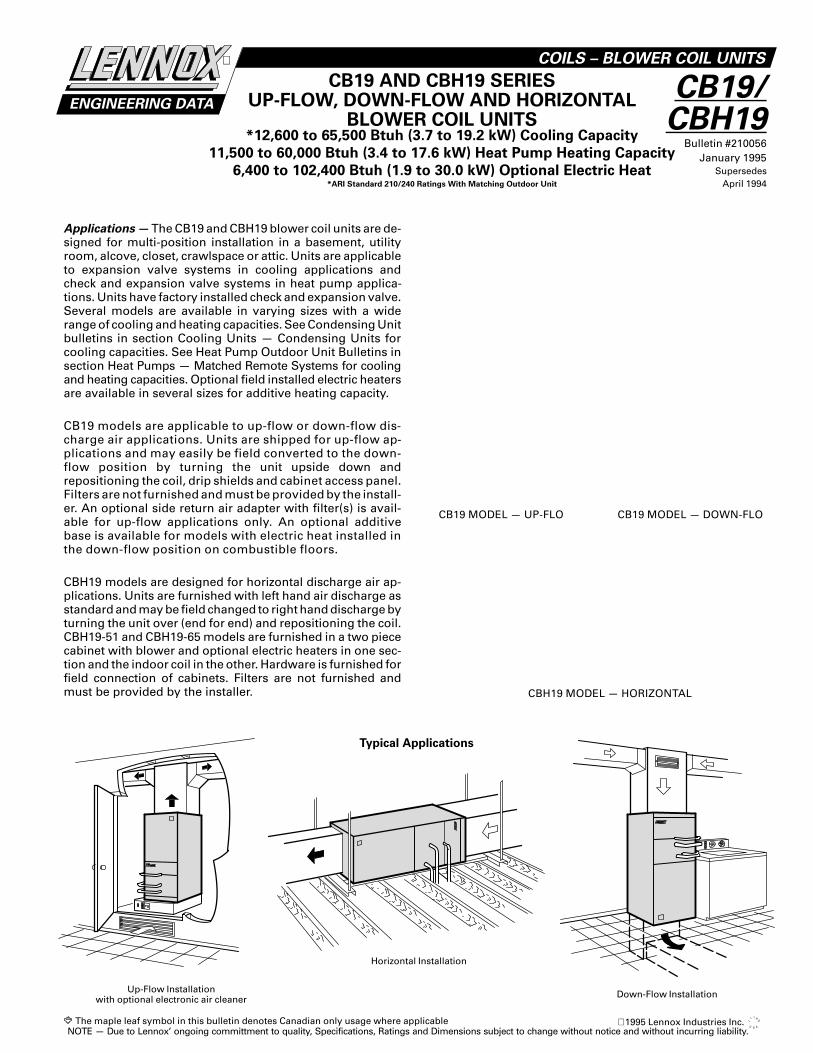
Down-Flow Installation
Typical Applications
Up-Flow Installationwith optional electronic air cleaner
Horizontal Installation
The maple leaf symbol in this bulletin denotes Canadian only usage where applicableNOTE — Due to Lennox’ ongoing committment to quality, Specifications, Ratings and Dimensions subject to change without notice and without incurring liability.
1995 Lennox Industries Inc.
FEATURES
Completely Tested — Blower coil units are tested with match-ing condensing units in the Lennox Research Laboratory envi-ronmental test room in accordance with ARI Standard210/240-89. Optional electric heaters are rated in accordancewith U.S. Department of Energy (DOE) test procedures andFederal Trade Commission (FTC) labeling regulations. Blowerperformance data is according to actual unit tests conductedin Lennox air test chamber. Blower-coil units and componentswithin are bonded for grounding to meet safety standards forservicing required by U.L., C.S.A., CEC and NEC.
Cabinet — Constructed of heavy gauge galvanized steel andcompletely insulated with thick fiberglass insulation. The pre-painted steel cabinets have a finish of mildly textured enamelwith a primer coat on the unpainted side of all panels. Remov-able panels provide complete service access. Electrical inletsare provided in both sides of cabinet. Return air entry is pos-sible in either side or bottom of cabinet on up-flow units.Drain Pan — Deep, corrosion resistant drain pan has dualpipe drains extended outside of cabinet for ease of connec-tion. See dimension drawings.
Direct Drive Blower — Equipped with a Lennox designed andbuilt direct drive blower. Each blower is statically and dynami-cally balanced as an assembly before it is installed in theunit. Multi-speed motor is resiliently mounted. A choice ofblower speeds is available. See blower performance tables.Change of blower speeds is easily accomplished by a simplechange in wiring.
Refrigerant Line Connections — Suction (vapor) and liquidlines have sweat connections and extend outside of the cabinetfor ease of connection. See dimension drawings for locations.Check and Expansion Valve Furnished — Check and expan-sion valve furnished and factory installed on all models.
Copper Tube/Enhanced Fin Evaporator Coil — Lennox de-signed twin coils, assembled in a ‘V’ configuration, providesextra large surface and contact area, excellent heat transferand low air resistance for maximum efficiency. Precise cir-cuiting gives uniform refrigerant distribution. Lennox fabri-cated coil is constructed of precisely spaced ripple-edged alu-minum fins fitted to durable seamless copper tubes. Fins arestrengthened to resist bending and are equipped with collarsthat grip tubing for maximum contact area. Lanced fins pro-vide maximum exposure of fin surface to air stream. Flaredshoulder tubing joints and silver soldering provide tight, leak-proof joints. Long life copper tubing is easy to field service.Coil is thoroughly factory tested under high pressure to in-sure leakproof construction.
Transformer and Blower Cooling Relay — A 24 volt trans-former and blower cooling relay are furnished as standardequipment and are factory installed in the unit control box.A terminal strip is also furnished as standard.
OPTIONAL ACCESSORIES (Must Be Ordered Extra)
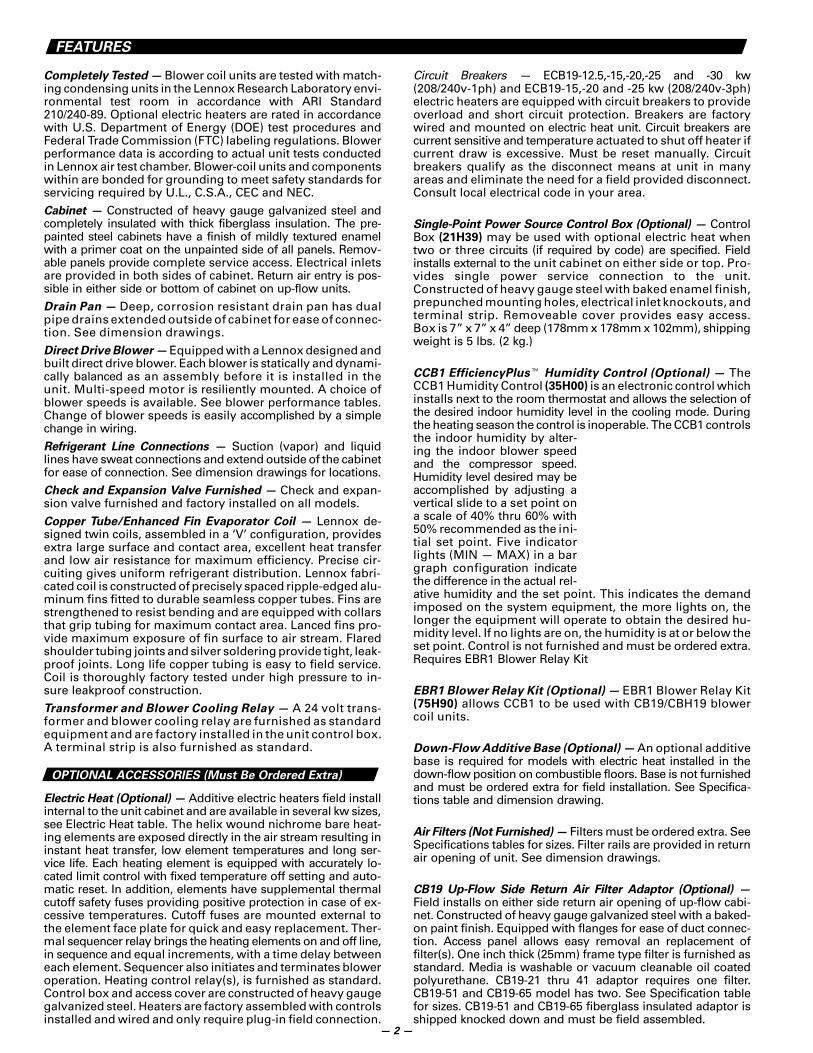
Electric Heat (Optional) — Additive electric heaters field installinternal to the unit cabinet and are available in several kw sizes,see Electric Heat table. The helix wound nichrome bare heat-ing elements are exposed directly in the air stream resulting ininstant heat transfer, low element temperatures and long ser-vice life. Each heating element is equipped with accurately lo-cated limit control with fixed temperature off setting and auto-matic reset. In addition, elements have supplemental thermalcutoff safety fuses providing positive protection in case of ex-cessive temperatures. Cutoff fuses are mounted external tothe element face plate for quick and easy replacement. Ther-mal sequencer relay brings the heating elements on and off line,in sequence and equal increments, with a time delay betweeneach element. Sequencer also initiates and terminates bloweroperation. Heating control relay(s), is furnished as standard.Control box and access cover are constructed of heavy gaugegalvanized steel. Heaters are factory assembled with controlsinstalled and wired and only require plug-in field connection.
Circuit Breakers — ECB19-12.5,-15,-20,-25 and -30 kw(208/240v-1ph) and ECB19-15,-20 and -25 kw (208/240v-3ph)electric heaters are equipped with circuit breakers to provideoverload and short circuit protection. Breakers are factorywired and mounted on electric heat unit. Circuit breakers arecurrent sensitive and temperature actuated to shut off heater ifcurrent draw is excessive. Must be reset manually. Circuitbreakers qualify as the disconnect means at unit in manyareas and eliminate the need for a field provided disconnect.Consult local electrical code in your area.
Single-Point Power Source Control Box (Optional) — ControlBox (21H39) may be used with optional electric heat whentwo or three circuits (if required by code) are specified. Fieldinstalls external to the unit cabinet on either side or top. Pro-vides single power service connection to the unit.Constructed of heavy gauge steel with baked enamel finish,prepunched mounting holes, electrical inlet knockouts, andterminal strip. Removeable cover provides easy access.Box is 7” x 7” x 4” deep (178mm x 178mm x 102mm), shippingweight is 5 lbs. (2 kg.)
CCB1 EfficiencyPlus� Humidity Control (Optional) — TheCCB1 Humidity Control (35H00) is an electronic control whichinstalls next to the room thermostat and allows the selection ofthe desired indoor humidity level in the cooling mode. Duringthe heating season the control is inoperable. The CCB1 controlsthe indoor humidity by alter-ing the indoor blower speedand the compressor speed.Humidity level desired may beaccomplished by adjusting avertical slide to a set point ona scale of 40% thru 60% with50% recommended as the ini-tial set point. Five indicatorlights (MIN — MAX) in a bargraph configuration indicatethe difference in the actual rel-ative humidity and the set point. This indicates the demandimposed on the system equipment, the more lights on, thelonger the equipment will operate to obtain the desired hu-midity level. If no lights are on, the humidity is at or below theset point. Control is not furnished and must be ordered extra.Requires EBR1 Blower Relay Kit
EBR1 Blower Relay Kit (Optional) — EBR1 Blower Relay Kit(75H90) allows CCB1 to be used with CB19/CBH19 blowercoil units.
Down-Flow Additive Base (Optional) — An optional additivebase is required for models with electric heat installed in thedown-flow position on combustible floors. Base is not furnishedand must be ordered extra for field installation. See Specifica-tions table and dimension drawing.
Air Filters (Not Furnished) — Filters must be ordered extra. SeeSpecifications tables for sizes. Filter rails are provided in returnair opening of unit. See dimension drawings.
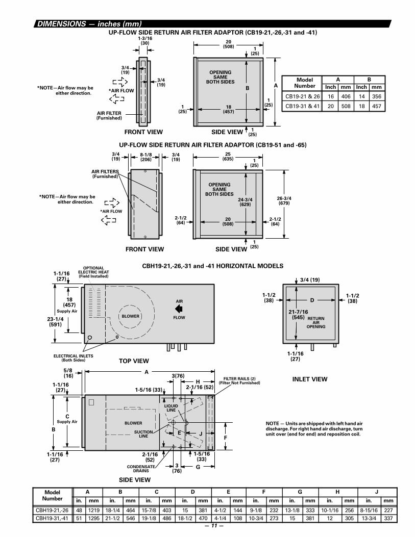
CB19 Up-Flow Side Return Air Filter Adaptor (Optional) —Field installs on either side return air opening of up-flow cabi-net. Constructed of heavy gauge galvanized steel with a baked-on paint finish. Equipped with flanges for ease of duct connec-tion. Access panel allows easy removal an replacement offilter(s). One inch thick (25mm) frame type filter is furnished asstandard. Media is washable or vacuum cleanable oil coatedpolyurethane. CB19-21 thru 41 adaptor requires one filter.CB19-51 and CB19-65 model has two. See Specification tablefor sizes. CB19-51 and CB19-65 fiberglass insulated adaptor isshipped knocked down and must be field assembled.
— 2 —
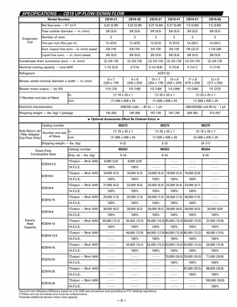
SPECIFICATIONS — CB19 UP-FLOW/DOWN-FLOW
Model Number CB19-21 CB19-26 CB19-31 CB19-41 CB19-51 CB19-65
Net face area — ft.2 (m2) 4.22 (0.39) 4.22 (0.39) 5.27 (0.49) 5.27 (0.49) 7.0 (0.65) 7.0 (0.65)
Tube outside diameter — in. (mm) 3/8 (9.5) 3/8 (9.5) 3/8 (9.5) 3/8 (9.5) 3/8 (9.5) 3/8 (9.5)
Evaporator Number of rows 3 3 3 3 3 3pCoil Fins per inch (fins per m) 12 (472) 12 (472) 13 (512) 13 (512) 14 (551) 14 (551)
Suct. (vapor) line conn. – in. (mm) sweat 5/8 (16) 5/8 (16) 3/4 (19) 3/4 (19) 7/8 (22.2) 1-1/8 (28)
Liquid line conn. — in. (mm) sweat 3/8 (9.5) 3/8 (9.5) 3/8 (9.5) 3/8 (9.5) 3/8 (9.5) 3/8 (9.5)
Condensate drain connection (pvc) — in. (mm) (2) 3/4 (19) (2) 3/4 (19) (2) 3/4 (19) (2) 3/4 (19) (2) 3/4 (19) (2) 3/4 (19)
Nominal cooling capacity — tons (kW) 1-1/2 (5.3) 2 (7.0) 2-1/2 (8.8) 3 (10.6) 4 (14.1) 5 (17.6)
Refrigerant HCFC-22
Blower wheel nominal diameter x width — in. (mm) 9 x 7(229 x 178)
9 x 8(229 x 203)
10 x 7(254 x 178)
10 x 9(254 x 229)
11 x 8(279 x 203)
12 x 9(317 x 229)
Blower motor output — hp (W) 1/10 (75) 1/5 (149) 1/3 (149) 1/3 (249) 1/3 (249) 1/2 (373)
��Number and size of filtersin. (1) 16 x 20 x 1 (1) 20 x 20 x 1 (1) 20 x 25 x 1
��Number and size of filtersmm (1) 406 x 508 x 25 (1) 508 x 508 x 25 (1) 508 x 635 x 25
Electrical characteristics 208/230 volts — 60 hz — 1 ph 208/230/460 volt 60 hz – 1 ph
Shipping weight — lbs. (kg) 1 package 143 (65) 146 (66) 167 (76) 167 (76) 209 (95) 213 (97)
� Optional Accessories (Must Be Ordered Extra) �
Catalog number 95G73 95G74 95G75
Side Return AirFilter Adaptor Number and size in. (1) 16 x 20 x 1 (1) 20 x 20 x 1 (2) 16 x 25 x 1Filter Adaptor
(Up-Flow Only) of filters mm (1) 406 x 508 x 25 (1) 508 x 508 x 25 (2) 406 x 635 x 25
Shipping weight — lbs. (kg) 4 (2) 5 (2) 24 (11)
Down-Flow Catalog number 85G52 85G53 85G54
Combustible Base Ship. wt. – lbs. (kg) 8 (4) 8 (4) 8 (4)
ECB19-2 5*Output — Btuh (kW) 9,000 (2.6) 9,500 (2.8) - - - - - - - - - - - - - - - -
ECB19-2.5�A.F.U.E. 100% 100% - - - - - - - - - - - - - - - -
ECB19-5*Output — Btuh (kW) 18,000 (5.3) 18,000 (5.3) 18,000 (5.3) 18,000 (5.3) 19,000 (5.6) - - - -
ECB19-5�A.F.U.E. 100% 100% 100% 100% 100% - - - -
ECB19-6*Output — Btuh (kW) 21,000 (6.2) 22,000 (6.4) 22,000 (6.4) 22,000 (6.4) 23,000 (6.7) - - - -
ECB19-6�A.F.U.E. 100% 100% 100% 100% 100% - - - -
ECB19-75*Output — Btuh (kW) 25,000 (7.3) 25,000 (7.3) 25,000 (7.3) 25,000 (7.3) 26,000 (7.6) - - - -
ECB19-75�A.F.U.E. 100% 100% 100% 100% 100% - - - -
ECB19-8*Output — Btuh (kW) 28,000 (8.2) 28,000 (8.2) 29,000 (8.5) 29,000 (8.5) 29,000 (8.5) 30,000 (8.8)
ECB19-8�A.F.U.E. 100% 100% 100% 100% 100% 100%
ElectricHeat ECB19-10
*Output — Btuh (kW) 35,000 (10.3) 35,000 (10.3) 35,000 (10.3) 35,000 (10.3) 36,000 (10.5) 37,000 (10.8)Heat
CapacityECB19-10
�A.F.U.E. 100% 100% 100% 100% 100% 100%
ECB19-12 5*Output — Btuh (kW) - - - - 44,000 (12.9) 44,000 (12.9) 44,000 (12.9) 45,000 (13.2) 46,000 (13.5)
ECB19-12.5�A.F.U.E. - - - - 100% 100% 100% 100% 100%
ECB19-15*Output — Btuh (kW) - - - - 52,000 (15.2) 52,000 (15.2) 53,000 (15.5) 53,000 (15.5) 54,000 (15.8)
ECB19-15�A.F.U.E. - - - - 100% 100% 100% 100% 100%
ECB19-20*Output — Btuh (kW) - - - - - - - - - - - - 70,000 (20.5) 70,000 (20.5) 71,000 (20.8)
ECB19-20�A.F.U.E. - - - - - - - - - - - - 100% 100% 100%
ECB19-25*Output — Btuh (kW) - - - - - - - - - - - - - - - - 87,000 (25.5) 88,000 (25.8)
ECB19-25�A.F.U.E. - - - - - - - - - - - - - - - - 100% 100%
ECB19-30*Output — Btuh (kW) - - - - - - - - - - - - - - - - - - - - 105,000 (30.8)
ECB19-30�A.F.U.E. - - - - - - - - - - - - - - - - - - - - 100%
�Annual Fuel Utilization Efficiency based on U.S. DOE test procedures and according to FTC labeling regulations��Filters are not furnished and must be ordered extra.*Includes additional blower motor heat capacity.
— 3 —
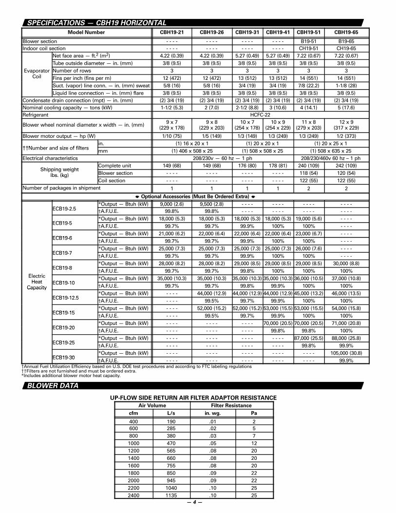
SPECIFICATIONS — CBH19 HORIZONTAL
Model Number CBH19-21 CBH19-26 CBH19-31 CBH19-41 CBH19-51 CBH19-65
Blower section - - - - - - - - - - - - - - - - B19-51 B19-65Indoor coil section - - - - - - - - - - - - - - - - CH19-51 CH19-65
Net face area — ft.2 (m2) 4.22 (0.39) 4.22 (0.39) 5.27 (0.49) 5.27 (0.49) 7.22 (0.67) 7.22 (0.67)Tube outside diameter — in. (mm) 3/8 (9.5) 3/8 (9.5) 3/8 (9.5) 3/8 (9.5) 3/8 (9.5) 3/8 (9.5)
Evaporator Number of rows 3 3 3 3 3 3Coil Fins per inch (fins per m) 12 (472) 12 (472) 13 (512) 13 (512) 14 (551) 14 (551)
Suct. (vapor) line conn. — in. (mm) sweat 5/8 (16) 5/8 (16) 3/4 (19) 3/4 (19) 7/8 (22.2) 1-1/8 (28)Liquid line connection — in. (mm) flare 3/8 (9.5) 3/8 (9.5) 3/8 (9.5) 3/8 (9.5) 3/8 (9.5) 3/8 (9.5)
Condensate drain connection (mpt) — in. (mm) (2) 3/4 (19) (2) 3/4 (19) (2) 3/4 (19) (2) 3/4 (19) (2) 3/4 (19) (2) 3/4 (19)Nominal cooling capacity — tons (kW) 1-1/2 (5.3) 2 (7.0) 2-1/2 (8.8) 3 (10.6) 4 (14.1) 5 (17.6)Refrigerant HCFC-22
Blower wheel nominal diameter x width — in. (mm) 9 x 7(229 x 178)
9 x 8(229 x 203)
10 x 7(254 x 178)
10 x 9(254 x 229)
11 x 8(279 x 203)
12 x 9(317 x 229)
Blower motor output — hp (W) 1/10 (75) 1/5 (149) 1/3 (149) 1/3 (249) 1/3 (249) 1/2 (373)
��N b a d i f filtin. (1) 16 x 20 x 1 (1) 20 x 20 x 1 (1) 20 x 25 x 1
��Number and size of filters mm (1) 406 x 508 x 25 (1) 508 x 508 x 25 (1) 508 x 635 x 25Electrical characteristics 208/230v — 60 hz — 1 ph 208/230/460v 60 hz – 1 ph
Shipping weightComplete unit 149 (68) 149 (68) 176 (80) 178 (81) 240 (109) 242 (109)
Shipping weightlbs. (kg) Blower section - - - - - - - - - - - - - - - - 118 (54) 120 (54)lbs. (kg)
Coil section - - - - - - - - - - - - - - - - 122 (55) 122 (55)Number of packages in shipment 1 1 1 1 2 2
� Optional Accessories (Must Be Ordered Extra) �
ECB19 2 5*Output — Btuh (kW) 9,000 (2.6) 9,500 (2.8) - - - - - - - - - - - - - - - -
ECB19-2.5�A.F.U.E. 99.8% 99.8% - - - - - - - - - - - - - - - -
ECB19 5*Output — Btuh (kW) 18,000 (5.3) 18,000 (5.3) 18,000 (5.3) 18,000 (5.3) 19,000 (5.6) - - - -
ECB19-5�A.F.U.E. 99.7% 99.7% 99.9% 100% 100% - - - -
ECB19 6*Output — Btuh (kW) 21,000 (6.2) 22,000 (6.4) 22,000 (6.4) 22,000 (6.4) 23,000 (6.7) - - - -
ECB19-6�A.F.U.E. 99.7% 99.7% 99.9% 100% 100% - - - -
ECB19 7*Output — Btuh (kW) 25,000 (7.3) 25,000 (7.3) 25,000 (7.3) 25,000 (7.3) 26,000 (7.6) - - - -
ECB19-7�A.F.U.E. 99.7% 99.7% 99.9% 100% 100% - - - -
ECB19 8*Output — Btuh (kW) 28,000 (8.2) 28,000 (8.2) 29,000 (8.5) 29,000 (8.5) 29,000 (8.5) 30,000 (8.8)
El t i
ECB19-8�A.F.U.E. 99.7% 99.7% 99.8% 100% 100% 100%
ElectricHeat ECB19 10
*Output — Btuh (kW) 35,000 (10.3) 35,000 (10.3) 35,000 (10.3) 35,000 (10.3) 36,000 (10.5) 37,000 (10.8)Heat
CapacityECB19-10
�A.F.U.E. 99.7% 99.7% 99.8% 99.9% 100% 100%Capacity
ECB19 12 5*Output — Btuh (kW) - - - - 44,000 (12.9) 44,000 (12.9) 44,000 (12.9) 45,000 (13.2) 46,000 (13.5)
ECB19-12.5�A.F.U.E. - - - - 99.5% 99.7% 99.9% 100% 100%
ECB19 15*Output — Btuh (kW) - - - - 52,000 (15.2) 52,000 (15.2) 53,000 (15.5) 53,000 (15.5) 54,000 (15.8)
ECB19-15�A.F.U.E. - - - - 99.5% 99.7% 99.9% 100% 100%
ECB19 20*Output — Btuh (kW) - - - - - - - - - - - - 70,000 (20.5) 70,000 (20.5) 71,000 (20.8)
ECB19-20�A.F.U.E. - - - - - - - - - - - - 99.8% 99.8% 100%
ECB19 25*Output — Btuh (kW) - - - - - - - - - - - - - - - - 87,000 (25.5) 88,000 (25.8)
ECB19-25�A.F.U.E. - - - - - - - - - - - - - - - - 99.8% 99.9%
ECB19 30*Output — Btuh (kW) - - - - - - - - - - - - - - - - - - - - 105,000 (30.8)
ECB19-30�A.F.U.E. - - - - - - - - - - - - - - - - - - - - 99.9%
�Annual Fuel Utilization Efficiency based on U.S. DOE test procedures and according to FTC labeling regulations��Filters are not furnished and must be ordered extra.*Includes additional blower motor heat capacity.
BLOWER DATA
UP-FLOW SIDE RETURN AIR FILTER ADAPTOR RESISTANCE
Air Volume Filter Resistance
cfm L/s in. wg. Pa
400 190 .01 2600 285 .02 5800 380 .03 71000 470 .05 121200 565 .08 201400 660 .08 201600 755 .08 201800 850 .09 222000 945 .09 222200 1040 .10 252400 1135 .10 25
— 4 —
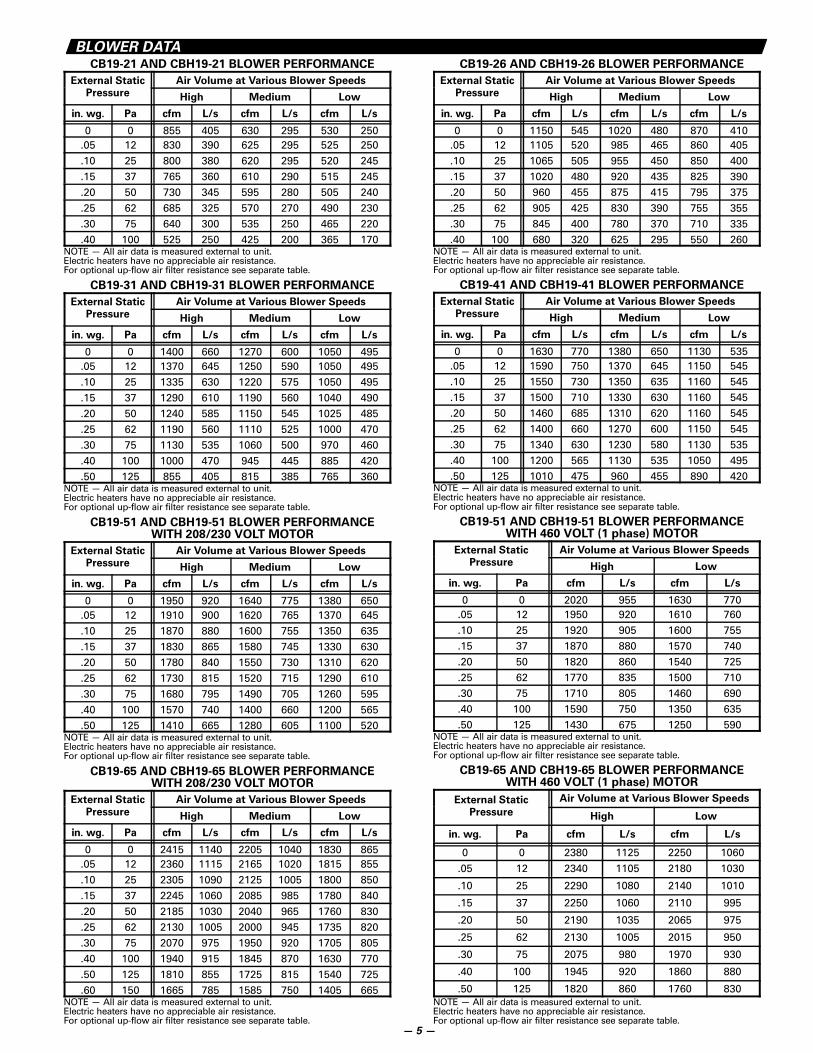
BLOWER DATACB19-21 AND CBH19-21 BLOWER PERFORMANCE
External Static Air Volume at Various Blower Speeds
Pressure High Medium Low
in. wg. Pa cfm L/s cfm L/s cfm L/s
0 0 855 405 630 295 530 250.05 12 830 390 625 295 525 250.10 25 800 380 620 295 520 245.15 37 765 360 610 290 515 245.20 50 730 345 595 280 505 240.25 62 685 325 570 270 490 230.30 75 640 300 535 250 465 220.40 100 525 250 425 200 365 170
NOTE — All air data is measured external to unit.Electric heaters have no appreciable air resistance.For optional up-flow air filter resistance see separate table.
CB19-31 AND CBH19-31 BLOWER PERFORMANCE
External Static Air Volume at Various Blower Speeds
Pressure High Medium Low
in. wg. Pa cfm L/s cfm L/s cfm L/s
0 0 1400 660 1270 600 1050 495.05 12 1370 645 1250 590 1050 495.10 25 1335 630 1220 575 1050 495.15 37 1290 610 1190 560 1040 490.20 50 1240 585 1150 545 1025 485.25 62 1190 560 1110 525 1000 470.30 75 1130 535 1060 500 970 460.40 100 1000 470 945 445 885 420.50 125 855 405 815 385 765 360
NOTE — All air data is measured external to unit.Electric heaters have no appreciable air resistance.For optional up-flow air filter resistance see separate table.
CB19-51 AND CBH19-51 BLOWER PERFORMANCEWITH 208/230 VOLT MOTOR
External Static Air Volume at Various Blower Speeds
Pressure High Medium Low
in. wg. Pa cfm L/s cfm L/s cfm L/s
0 0 1950 920 1640 775 1380 650.05 12 1910 900 1620 765 1370 645.10 25 1870 880 1600 755 1350 635.15 37 1830 865 1580 745 1330 630.20 50 1780 840 1550 730 1310 620.25 62 1730 815 1520 715 1290 610.30 75 1680 795 1490 705 1260 595.40 100 1570 740 1400 660 1200 565.50 125 1410 665 1280 605 1100 520
NOTE — All air data is measured external to unit.Electric heaters have no appreciable air resistance.For optional up-flow air filter resistance see separate table.
CB19-65 AND CBH19-65 BLOWER PERFORMANCEWITH 208/230 VOLT MOTOR
External Static Air Volume at Various Blower Speeds
Pressure High Medium Low
in. wg. Pa cfm L/s cfm L/s cfm L/s
0 0 2415 1140 2205 1040 1830 865.05 12 2360 1115 2165 1020 1815 855.10 25 2305 1090 2125 1005 1800 850.15 37 2245 1060 2085 985 1780 840.20 50 2185 1030 2040 965 1760 830.25 62 2130 1005 2000 945 1735 820.30 75 2070 975 1950 920 1705 805.40 100 1940 915 1845 870 1630 770.50 125 1810 855 1725 815 1540 725.60 150 1665 785 1585 750 1405 665
NOTE — All air data is measured external to unit.Electric heaters have no appreciable air resistance.For optional up-flow air filter resistance see separate table.
CB19-26 AND CBH19-26 BLOWER PERFORMANCE
External Static Air Volume at Various Blower Speeds
Pressure High Medium Low
in. wg. Pa cfm L/s cfm L/s cfm L/s
0 0 1150 545 1020 480 870 410.05 12 1105 520 985 465 860 405.10 25 1065 505 955 450 850 400.15 37 1020 480 920 435 825 390.20 50 960 455 875 415 795 375.25 62 905 425 830 390 755 355.30 75 845 400 780 370 710 335.40 100 680 320 625 295 550 260
NOTE — All air data is measured external to unit.Electric heaters have no appreciable air resistance.For optional up-flow air filter resistance see separate table.
CB19-41 AND CBH19-41 BLOWER PERFORMANCE
External Static Air Volume at Various Blower Speeds
Pressure High Medium Low
in. wg. Pa cfm L/s cfm L/s cfm L/s
0 0 1630 770 1380 650 1130 535.05 12 1590 750 1370 645 1150 545.10 25 1550 730 1350 635 1160 545.15 37 1500 710 1330 630 1160 545.20 50 1460 685 1310 620 1160 545.25 62 1400 660 1270 600 1150 545.30 75 1340 630 1230 580 1130 535.40 100 1200 565 1130 535 1050 495.50 125 1010 475 960 455 890 420
NOTE — All air data is measured external to unit.Electric heaters have no appreciable air resistance.For optional up-flow air filter resistance see separate table.
CB19-51 AND CBH19-51 BLOWER PERFORMANCEWITH 460 VOLT (1 phase) MOTOR
External Static Air Volume at Various Blower Speeds
Pressure High Low
in. wg. Pa cfm L/s cfm L/s
0 0 2020 955 1630 770.05 12 1950 920 1610 760.10 25 1920 905 1600 755.15 37 1870 880 1570 740.20 50 1820 860 1540 725.25 62 1770 835 1500 710.30 75 1710 805 1460 690.40 100 1590 750 1350 635.50 125 1430 675 1250 590
NOTE — All air data is measured external to unit.Electric heaters have no appreciable air resistance.For optional up-flow air filter resistance see separate table.
CB19-65 AND CBH19-65 BLOWER PERFORMANCEWITH 460 VOLT (1 phase) MOTOR
External Static Air Volume at Various Blower Speeds
Pressure High Low
in. wg. Pa cfm L/s cfm L/s
0 0 2380 1125 2250 1060.05 12 2340 1105 2180 1030
.10 25 2290 1080 2140 1010
.15 37 2250 1060 2110 995
.20 50 2190 1035 2065 975
.25 62 2130 1005 2015 950
.30 75 2075 980 1970 930
.40 100 1945 920 1860 880
.50 125 1820 860 1760 830NOTE — All air data is measured external to unit.Electric heaters have no appreciable air resistance.For optional up-flow air filter resistance see separate table.
— 5 —
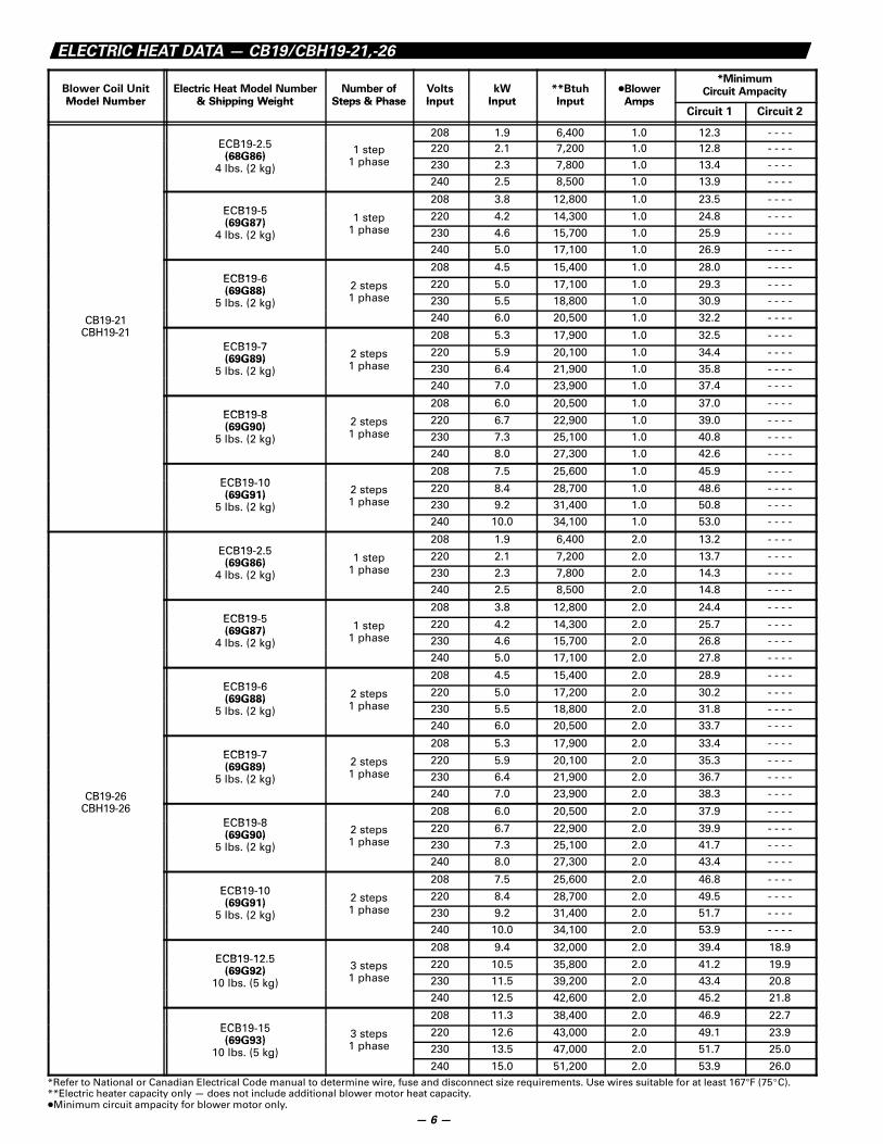
ELECTRIC HEAT DATA — CB19/CBH19-21,-26
Blower Coil UnitModel Number
Electric Heat Model Number& Shipping Weight
Number ofSteps & Phase
VoltsInput
kWInput
**BtuhInput
�BlowerAmps
*MinimumCircuit Ampacity
Model Number & Shipping Weight Steps & Phase Input Input Input AmpsCircuit 1 Circuit 2
ECB19 2 5208 1.9 6,400 1.0 12.3 - - - -
ECB19-2.5(68G86)
1 steph
220 2.1 7,200 1.0 12.8 - - - -(68G86)
4 lbs. (2 kg) 1 phase 230 2.3 7,800 1.0 13.4 - - - -( g)240 2.5 8,500 1.0 13.9 - - - -
ECB19 5208 3.8 12,800 1.0 23.5 - - - -
ECB19-5(69G87)
1 steph
220 4.2 14,300 1.0 24.8 - - - -(69G87)
4 lbs. (2 kg) 1 phase 230 4.6 15,700 1.0 25.9 - - - -g240 5.0 17,100 1.0 26.9 - - - -
ECB19 6208 4.5 15,400 1.0 28.0 - - - -
ECB19-6(69G88)
2 stepsh
220 5.0 17,100 1.0 29.3 - - - -(69G88)
5 lbs. (2 kg) 1 phase 230 5.5 18,800 1.0 30.9 - - - -
CB19-21
g240 6.0 20,500 1.0 32.2 - - - -
CBH19-21ECB19 7
208 5.3 17,900 1.0 32.5 - - - -ECB19-7(69G89)
2 stepsh
220 5.9 20,100 1.0 34.4 - - - -(69G89)
5 lbs. (2 kg) 1 phase 230 6.4 21,900 1.0 35.8 - - - -g240 7.0 23,900 1.0 37.4 - - - -
ECB19 8208 6.0 20,500 1.0 37.0 - - - -
ECB19-8(69G90)
2 stepsh
220 6.7 22,900 1.0 39.0 - - - -(69G90)
5 lbs. (2 kg) 1 phase 230 7.3 25,100 1.0 40.8 - - - -g240 8.0 27,300 1.0 42.6 - - - -
ECB19 10208 7.5 25,600 1.0 45.9 - - - -
ECB19-10(69G91)
2 stepsh
220 8.4 28,700 1.0 48.6 - - - -(69G91)
5 lbs. (2 kg) 1 phase 230 9.2 31,400 1.0 50.8 - - - -g240 10.0 34,100 1.0 53.0 - - - -
ECB19 2 5208 1.9 6,400 2.0 13.2 - - - -
ECB19-2.5(69G86)
1 steph
220 2.1 7,200 2.0 13.7 - - - -(69G86)
4 lbs. (2 kg) 1 phase 230 2.3 7,800 2.0 14.3 - - - -g240 2.5 8,500 2.0 14.8 - - - -
ECB19 5208 3.8 12,800 2.0 24.4 - - - -
ECB19-5(69G87)
1 steph
220 4.2 14,300 2.0 25.7 - - - -(69G87)
4 lbs. (2 kg) 1 phase 230 4.6 15,700 2.0 26.8 - - - -g240 5.0 17,100 2.0 27.8 - - - -
ECB19 6208 4.5 15,400 2.0 28.9 - - - -
ECB19-6(69G88)
2 stepsh
220 5.0 17,200 2.0 30.2 - - - -(69G88)
5 lbs. (2 kg) 1 phase 230 5.5 18,800 2.0 31.8 - - - -g240 6.0 20,500 2.0 33.7 - - - -
ECB19 7208 5.3 17,900 2.0 33.4 - - - -
ECB19-7(69G89)
2 stepsh
220 5.9 20,100 2.0 35.3 - - - -(69G89)
5 lbs. (2 kg) 1 phase 230 6.4 21,900 2.0 36.7 - - - -
CB19-26
g240 7.0 23,900 2.0 38.3 - - - -
CBH19-26ECB19 8
208 6.0 20,500 2.0 37.9 - - - -ECB19-8(69G90)
2 stepsh
220 6.7 22,900 2.0 39.9 - - - -(69G90)
5 lbs. (2 kg) 1 phase 230 7.3 25,100 2.0 41.7 - - - -g240 8.0 27,300 2.0 43.4 - - - -
ECB19 10208 7.5 25,600 2.0 46.8 - - - -
ECB19-10(69G91)
2 stepsh
220 8.4 28,700 2.0 49.5 - - - -(69G91)
5 lbs. (2 kg) 1 phase 230 9.2 31,400 2.0 51.7 - - - -g240 10.0 34,100 2.0 53.9 - - - -
ECB19 12 5208 9.4 32,000 2.0 39.4 18.9
ECB19-12.5(69G92)
3 stepsh
220 10.5 35,800 2.0 41.2 19.9(69G92)
10 lbs. (5 kg) 1 phase 230 11.5 39,200 2.0 43.4 20.8g240 12.5 42,600 2.0 45.2 21.8
ECB19 15208 11.3 38,400 2.0 46.9 22.7
ECB19-15(69G93)
3 stepsh
220 12.6 43,000 2.0 49.1 23.9(69G93)
10 lbs. (5 kg) 1 phase 230 13.5 47,000 2.0 51.7 25.0( g)240 15.0 51,200 2.0 53.9 26.0
*Refer to National or Canadian Electrical Code manual to determine wire, fuse and disconnect size requirements. Use wires suitable for at least 167°F (75�C).**Electric heater capacity only — does not include additional blower motor heat capacity.�Minimum circuit ampacity for blower motor only.
— 6 —
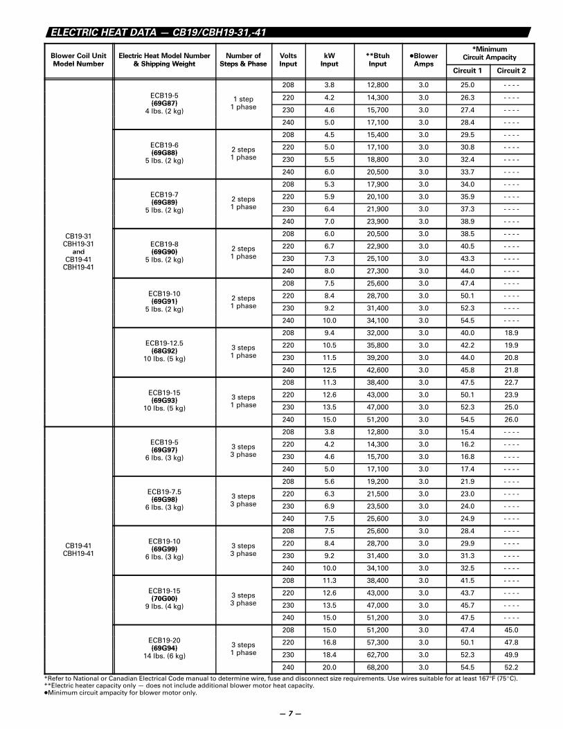
ELECTRIC HEAT DATA — CB19/CBH19-31,-41
Blower Coil UnitModel Number
Electric Heat Model Number& Shipping Weight
Number ofSteps & Phase
VoltsInput
kWInput
**BtuhInput
�BlowerAmps
*MinimumCircuit Ampacity
Model Number & Shipping Weight Steps & Phase Input Input Input AmpsCircuit 1 Circuit 2
208 3.8 12,800 3.0 25.0 - - - -
ECB19-5(69G87)
1 steph
220 4.2 14,300 3.0 26.3 - - - -(69G87)
4 lbs. (2 kg) 1 phase 230 4.6 15,700 3.0 27.4 - - - -
240 5.0 17,100 3.0 28.4 - - - -
208 4.5 15,400 3.0 29.5 - - - -ECB19-6(69G88)
2 steps 220 5.0 17,100 3.0 30.8 - - - -(69G88)
5 lbs. (2 kg)
p1 phase 230 5.5 18,800 3.0 32.4 - - - -
240 6.0 20,500 3.0 33.7 - - - -
208 5.3 17,900 3.0 34.0 - - - -ECB19-7(69G89)
2 steps 220 5.9 20,100 3.0 35.9 - - - -(69G89)
5 lbs. (2 kg)
p1 phase 230 6.4 21,900 3.0 37.3 - - - -
240 7.0 23,900 3.0 38.9 - - - -
CB19-31 208 6.0 20,500 3.0 38.5 - - - -CBH19-31
andECB19-8(69G90)
2 steps 220 6.7 22,900 3.0 40.5 - - - -and
CB19-41CBH19 41
(69G90)5 lbs. (2 kg)
p1 phase 230 7.3 25,100 3.0 43.3 - - - -
CBH19-41 240 8.0 27,300 3.0 44.0 - - - -
208 7.5 25,600 3.0 47.4 - - - -ECB19-10(69G91)
2 steps 220 8.4 28,700 3.0 50.1 - - - -(69G91)
5 lbs. (2 kg)
p1 phase 230 9.2 31,400 3.0 52.3 - - - -
240 10.0 34,100 3.0 54.5 - - - -
208 9.4 32,000 3.0 40.0 18.9ECB19-12.5
(68G92)3 steps 220 10.5 35,800 3.0 42.2 19.9
(68G92)10 lbs. (5 kg)
p1 phase 230 11.5 39,200 3.0 44.0 20.8
240 12.5 42,600 3.0 45.8 21.8
208 11.3 38,400 3.0 47.5 22.7ECB19-15(69G93)
3 steps 220 12.6 43,000 3.0 50.1 23.9(69G93)
10 lbs. (5 kg)
p1 phase 230 13.5 47,000 3.0 52.3 25.0
240 15.0 51,200 3.0 54.5 26.0
208 3.8 12,800 3.0 15.4 - - - -ECB19-5(69G97)
3 steps 220 4.2 14,300 3.0 16.2 - - - -(69G97)
6 lbs. (3 kg)
p3 phase 230 4.6 15,700 3.0 16.8 - - - -
240 5.0 17,100 3.0 17.4 - - - -
208 5.6 19,200 3.0 21.9 - - - -ECB19-7.5
(69G98)3 steps 220 6.3 21,500 3.0 23.0 - - - -
(69G98)6 lbs. (3 kg)
p3 phase 230 6.9 23,500 3.0 24.0 - - - -
240 7.5 25,600 3.0 24.9 - - - -
208 7.5 25,600 3.0 28.4 - - - -
CB19-41ECB19-10(69G99)
3 steps 220 8.4 28,700 3.0 29.9 - - - -CBH19-41
(69G99)6 lbs. (3 kg)
p3 phase 230 9.2 31,400 3.0 31.3 - - - -
240 10.0 34,100 3.0 32.5 - - - -
208 11.3 38,400 3.0 41.5 - - - -ECB19-15(70G00)
3 steps 220 12.6 43,000 3.0 43.7 - - - -(70G00)
9 lbs. (4 kg)
p3 phase 230 13.5 47,000 3.0 45.7 - - - -
240 15.0 51,200 3.0 47.5 - - - -
208 15.0 51,200 3.0 47.4 45.0ECB19-20(69G94)
3 steps 220 16.8 57,300 3.0 50.1 47.8(69G94)
14 lbs. (6 kg)
p1 phase 230 18.4 62,700 3.0 52.3 49.9
240 20.0 68,200 3.0 54.5 52.2
*Refer to National or Canadian Electrical Code manual to determine wire, fuse and disconnect size requirements. Use wires suitable for at least 167°F (75�C).**Electric heater capacity only — does not include additional blower motor heat capacity.�Minimum circuit ampacity for blower motor only.
— 7 —
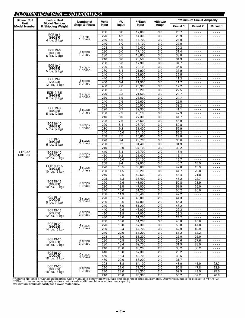
ELECTRIC HEAT DATA — CB19/CBH19-51
Blower CoilUnit
Electric HeatModel Number
Number of&
Volts kW **Btuh �Blower*Minimum Circuit Ampacity
UnitModel Number
Model Number& Shipping Weight
Steps & Phase Input Input Input Amps Circuit 1 Circuit 2 Circuit 3
ECB19 5208 3.8 12,800 3.0 25.7 - - - - - - - -
ECB19-5(69G87) 1 step 220 4.2 14,300 3.0 26.9 - - - - - - - -(69G87)
4 lbs. (2 kg)1 step
1 phase 230 4.6 15,700 3.0 28.0 - - - - - - - -4 lbs. (2 kg)240 5.0 17,100 3.0 29.0 - - - - - - - -
ECB19 6208 4.5 15,400 3.0 30.2 - - - - - - - -
ECB19-6(69G88) 2 steps 220 5.0 17,100 3.0 31.4 - - - - - - - -(69G88)
5 lbs. (2 kg)2 steps1 phase 230 5.5 18,800 3.0 33.0 - - - - - - - -5 lbs. (2 kg)
240 6.0 20,500 3.0 34.3 - - - - - - - -
ECB19 7208 5.3 17,900 3.0 34.7 - - - - - - - -
ECB19-7(69G89) 2 steps 220 5.9 20,100 3.0 36.6 - - - - - - - -(69G89)
5 lbs. (2 kg)2 steps1 phase 230 6.4 21,900 3.0 37.9 - - - - - - - -5 lbs. (2 kg)
240 7.0 23,900 3.0 39.5 - - - - - - - -ECB19-7 3 steps
440 5.9 20,100 3.0 11.3 - - - - - - - -ECB19 7(70G03)
12 lb (5 k )3 steps3 phase 460 6.4 21,900 3.0 11.7 - - - - - - - -
12 lbs. (5 kg) 3 phase480 7.0 25,900 3.0 12.2 - - - - - - - -
ECB19 7 5208 5.6 19,200 3.0 22.5 - - - - - - - -
ECB19-7.5(69G98) 3 steps 220 6.3 21,500 3.0 23.7 - - - - - - - -(69G98)
6 lbs. (3 kg)3 steps3 phase 230 6.9 23,500 3.0 24.7 - - - - - - - -6 lbs. (3 kg)
240 7.5 25,600 3.0 25.5 - - - - - - - -
ECB19 8208 6.0 20,500 3.0 39.2 - - - - - - - -
ECB19-8(69G90) 2 steps 220 6.7 22,900 3.0 41.1 - - - - - - - -(69G90)
5 lbs. (2 kg)2 steps1 phase 230 7.3 25,100 3.0 42.9 - - - - - - - -5 lbs. (2 kg)
240 8.0 27,300 3.0 44.7 - - - - - - - -
ECB19 10208 7.5 25,600 3.0 48.0 - - - - - - - -
ECB19-10(69G91) 2 steps 220 8.4 28,700 3.0 50.8 - - - - - - - -(69G91)
5 lbs. (2 kg)2 steps1 phase 230 9.2 31,400 3.0 52.9 - - - - - - - -5 lbs. (2 kg)
240 10.0 34,100 3.0 55.2 - - - - - - - -
ECB19 10208 7.5 25,600 3.0 29.0 - - - - - - - -
ECB19-10(69G99) 3 steps 220 8.4 28,700 3.0 30.6 - - - - - - - -(69G99)
6 lbs. (3 kg)3 steps3 phase 230 9.2 31,400 3.0 31.9 - - - - - - - -6 lbs. (3 kg)
240 10.0 34,100 3.0 33.2 - - - - - - - -CB19-51 ECB19-10 3 steps
440 8.4 28,700 2.0 15.4 - - - - - - - -CB19 51CBH19-51
ECB19 10(70G04)
12 lb (5 k )3 steps3 phase 460 9.2 31,400 2.0 16.1 - - - - - - - -
12 lbs. (5 kg) 3 phase480 10.0 34,100 2.0 16.7 - - - - - - - -
ECB19 12 5208 9.4 32,000 3.0 40.7 18.9 - - - -
ECB19-12.5(68G92) 3 steps 220 10.5 35,800 3.0 42.8 19.9 - - - -(68G92)
10 lbs. (5 kg)3 steps1 phase 230 11.5 39,200 3.0 44.7 20.8 - - - -10 lbs. (5 kg)
240 12.5 42,600 3.0 46.4 21.8 - - - -
ECB19 15208 11.3 38,400 3.0 48.2 22.7 - - - -
ECB19-15(69G93) 3 steps 220 12.6 43,000 3.0 50.8 23.9 - - - -(69G93)
10 lbs. (5 kg)3 steps1 phase 230 13.5 47,000 3.0 52.9 25.0 - - - -10 lbs. (5 kg)
240 15.0 51,200 3.0 55.2 26.0 - - - -
ECB19 15208 11.3 38,400 2.0 42.2 - - - - - - - -
ECB19-15(70G00) 3 steps 220 12.6 43,000 2.0 44.3 - - - - - - - -(70G00)
9 lbs. (4 kg)3 steps3 phase 230 13.5 47,000 2.0 46.3 - - - - - - - -9 lbs. (4 kg)
240 15.0 51,200 2.0 48.2 - - - - - - - -ECB19-15 3 steps
440 12.6 43,000 2.0 22.3 - - - - - - - -ECB19 15(70G05)
12 lb (5 k )3 steps3 phase 460 13.8 47,000 2.0 23.3 - - - - - - - -
12 lbs. (5 kg) 3 phase480 15.0 51,200 2.0 24.2 - - - - - - - -
ECB19 20208 15.0 51,200 3.0 48.0 45.0 - - - -
ECB19-20(69G94) 4 steps 220 16.8 57,300 3.0 50.8 47.8 - - - -(69G94)
14 lbs. (6 kg)4 steps1 phase 230 18.4 62,700 3.0 52.9 49.9 - - - -14 lbs. (6 kg)
240 20.0 68,200 3.0 55.2 52.2 - - - -
ECB19 20208 15.0 51,200 2.0 29.0 26.0 - - - -
ECB19-20(70G01) 6 steps 220 16.8 57,300 2.0 30.6 27.6 - - - -(70G01)
19 lbs. (9 kg)6 steps3 phase 230 18.4 62,700 2.0 31.9 28.9 - - - -19 lbs. (9 kg)
240 20.0 68,200 2.0 33.2 30.2 - - - -ECB19-20 6 steps
440 16.8 57,300 2.0 29.2 - - - - - - - -ECB19 20(70G06)
18 lb (8 k )6 steps3 phase 460 18.4 62,700 2.0 30.5 - - - - - - - -
18 lbs. (8 kg) 3 phase480 20.0 68,200 2.0 31.7 - - - - - - - -
ECB19 25208 18.8 64,100 2.0 48.0 45.0 22.7
ECB19-25(69G95) 5 steps 220 21.0 71,700 2.0 50.8 47.8 23.9(69G95)
18 lbs. (8 kg)5 steps1 phase 230 23.0 78,300 2.0 52.9 49.9 25.018 lbs. (8 kg)
240 25.0 85,300 2.0 55.2 52.2 26.0*Refer to National or Canadian Electrical Code manual to determine wire, fuse and disconnect size requirements. Use wires suitable for at least 167°F (75�C).**Electric heater capacity only — does not include additional blower motor heat capacity.�Minimum circuit ampacity for blower motor only.
— 8 —
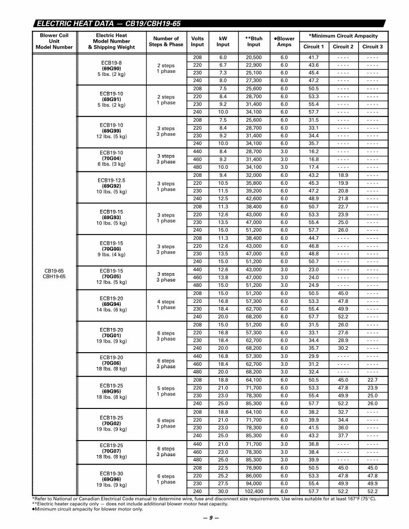
ELECTRIC HEAT DATA — CB19/CBH19-65
Blower CoilUnit
Electric HeatModel Number
Number of Volts kW **Btuh �Blower*Minimum Circuit Ampacity
Unit
Model Number
Model Number
& Shipping WeightSteps & Phase Input Input Input Amps Circuit 1 Circuit 2 Circuit 3
ECB19 8208 6.0 20,500 6.0 41.7 - - - - - - - -
ECB19-8(69G90)
2 stepsh
220 6.7 22,900 6.0 43.6 - - - - - - - -(69G90)
5 lbs. (2 kg) 1 phase 230 7.3 25,100 6.0 45.4 - - - - - - - -( g)240 8.0 27,300 6.0 47.2 - - - - - - - -
ECB19 10208 7.5 25,600 6.0 50.5 - - - - - - - -
ECB19-10(69G91)
2 stepsh
220 8.4 28,700 6.0 53.3 - - - - - - - -(69G91)
5 lbs. (2 kg) 1 phase 230 9.2 31,400 6.0 55.4 - - - - - - - -g240 10.0 34,100 6.0 57.7 - - - - - - - -
ECB19 10208 7.5 25,600 6.0 31.5 - - - - - - - -
ECB19-10(69G99)
3 steps3 h
220 8.4 28,700 6.0 33.1 - - - - - - - -(69G99)
12 lbs. (5 kg) 3 phase 230 9.2 31,400 6.0 34.4 - - - - - - - -g240 10.0 34,100 6.0 35.7 - - - - - - - -
ECB19-103 steps
440 8.4 28,700 3.0 16.2 - - - - - - - -(70G04)
6 lbs (3 kg)
3 steps3 phase 460 9.2 31,400 3.0 16.8 - - - - - - - -
6 lbs. (3 kg) 3 phase480 10.0 34,100 3.0 17.4 - - - - - - - -
ECB19 12 5208 9.4 32,000 6.0 43.2 18.9 - - - -
ECB19-12.5(69G92)
3 stepsh
220 10.5 35,800 6.0 45.3 19.9 - - - -(69G92)
10 lbs. (5 kg) 1 phase 230 11.5 39,200 6.0 47.2 20.8 - - - -g240 12.5 42,600 6.0 48.9 21.8 - - - -
ECB19 15208 11.3 38,400 6.0 50.7 22.7 - - - -
ECB19-15(69G93)
3 stepsh
220 12.6 43,000 6.0 53.3 23.9 - - - -(69G93)
10 lbs. (5 kg) 1 phase 230 13.5 47,000 6.0 55.4 25.0 - - - -g240 15.0 51,200 6.0 57.7 26.0 - - - -
ECB19 15208 11.3 38,400 6.0 44.7 - - - - - - - -
ECB19-15(70G00)
3 stepsh
220 12.6 43,000 6.0 46.8 - - - - - - - -(70G00)
9 lbs. (4 kg) 3 phase 230 13.5 47,000 6.0 48.8 - - - - - - - -g240 15.0 51,200 6.0 50.7 - - - - - - - -
CB19-65 ECB19-153 steps
440 12.6 43,000 3.0 23.0 - - - - - - - -CBH19-65 (70G05)
12 lbs (5 kg)
3 steps3 phase 460 13.8 47,000 3.0 24.0 - - - - - - - -
12 lbs. (5 kg) 3 phase480 15.0 51,200 3.0 24.9 - - - - - - - -
ECB19 20208 15.0 51,200 6.0 50.5 45.0 - - - -
ECB19-20(69G94)
4 stepsh
220 16.8 57,300 6.0 53.3 47.8 - - - -(69G94)
14 lbs. (6 kg) 1 phase 230 18.4 62,700 6.0 55.4 49.9 - - - -g240 20.0 68,200 6.0 57.7 52.2 - - - -
ECB19 20208 15.0 51,200 6.0 31.5 26.0 - - - -
ECB19-20(70G01)
6 stepsh
220 16.8 57,300 6.0 33.1 27.6 - - - -(70G01)
19 lbs. (9 kg) 3 phase 230 18.4 62,700 6.0 34.4 28.9 - - - -g240 20.0 68,200 6.0 35.7 30.2 - - - -
ECB19-206 steps
440 16.8 57,300 3.0 29.9 - - - - - - - -(70G06)
18 lbs (8 kg)
6 steps3 phase 460 18.4 62,700 3.0 31.2 - - - - - - - -
18 lbs. (8 kg) 3 phase480 20.0 68,200 3.0 32.4 - - - - - - - -
ECB19 25208 18.8 64,100 6.0 50.5 45.0 22.7
ECB19-25(69G95)
5 stepsh
220 21.0 71,700 6.0 53.3 47.8 23.9(69G95)
18 lbs. (8 kg) 1 phase 230 23.0 78,300 6.0 55.4 49.9 25.0( g)240 25.0 85,300 6.0 57.7 52.2 26.0
ECB19 25208 18.8 64,100 6.0 38.2 32.7 - - - -
ECB19-25(70G02)
6 steps3 h
220 21.0 71,700 6.0 39.9 34.4 - - - -(70G02)
19 lbs. (9 kg) 3 phase 230 23.0 78,300 6.0 41.5 36.0 - - - -( g)240 25.0 85,300 6.0 43.2 37.7 - - - -
ECB19-256 steps
440 21.0 71,700 3.0 36.8 - - - - - - - -(70G07)
18 lbs (8 kg)
6 steps3 phase 460 23.0 78,300 3.0 38.4 - - - - - - - -
18 lbs. (8 kg) 3 phase480 25.0 85,300 3.0 39.9 - - - - - - - -
ECB19 30208 22.5 76,900 6.0 50.5 45.0 45.0
ECB19-30(69G96)
6 stepsh
220 25.2 86,000 6.0 53.3 47.8 47.8(69G96)
19 lbs. (9 kg) 1 phase 230 27.5 94,000 6.0 55.4 49.9 49.9( g)240 30.0 102,400 6.0 57.7 52.2 52.2
*Refer to National or Canadian Electrical Code manual to determine wire, fuse and disconnect size requirements. Use wires suitable for at least 167°F (75�C).**Electric heater capacity only — does not include additional blower motor heat capacity.�Minimum circuit ampacity for blower motor only.
— 9 —
F
OPTIONALELECTRIC HEAT(Field Installed)
1-1/16 (27)
1-1/16(27)
SUPPLYAIR
OPENING
E
D
B C
A
1-1/16(27)
1-1/2(38)
4-1/4 (108)
2-1/2 (64)
3 (76)
BLOWER
RETURN AIROPENING
(Either Sideor Bottom)
AIR FLOW
K
J
G
M
BLOWER
Return AirReturn Air
LIQUIDLINE
SUCTIONLINE
CONDENSATEDRAINS (2)
FILTERRAILS (2)(Filter NotFurnished)
ELECTRICAL INLETS(Both Sides)
N
5/8(16)
H
1-1/2(38)
3/4(19)
P
1-1/16(27)
1-1/16(27)
TOP VIEW
FRONT VIEW SIDE VIEW
L
ABLOWER
3/4(19) F
G
C B
ED
M
3(76)
J
FILTER RAILS (2)(Filter Not Furnished)
AIR
FLOW
Supply Air Supply Air
ELECTRICALINLETS
(Both Sides)
CONDENSATEDRAINS (2)
LIQUIDLINE
SUCTIONLINE
RETURNAIR
OPENING
5/8(16)
1-1/16(27)
L
H
K
1-1/16(27)
1-1/2 (38)
TOP VIEW
1-1/2 (38)
FRONT VIEWSIDE VIEW
1-1/16(27)
BLOWER
OPTIONALELECTRIC HEAT(Field Installed)
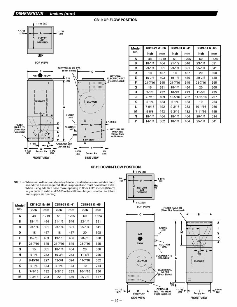
NOTE — When unit with optional electric heat is installed on a combustible floor,an additive base is required. Base is optional and must be ordered extra.When using additive base make opening in floor 2-3/8 inches (60mm)larger (side to side) and 2-1/2 inches (64mm) larger (front to rear) thanunit supply air opening.
DIMENSIONS — inches (mm)
CB19 UP-FLOW POSITION
Model
N
CB19-21 & -26 CB19-31 & -41 CB19-51 & -65
No.inch mm inch mm inch mm
A 48 1219 51 1295 60 1524B 18-1/4 464 21-1/2 546 23-1/4 591
C 23-1/4 591 23-1/4 591 25-1/4 641
D 18 457 18 457 20 508
E 15-7/8 403 19-1/8 486 20-7/8 530
F 21-7/16 545 21-7/16 545 23-7/16 595
G 15 381 18-1/4 464 20 508
H 9-1/8 232 10-3/4 273 11-5/8 295
J 7-7/16 189 10-5/16 262 11-11/16 297
K 5-1/4 133 5-1/4 133 10 254
L 7-9/16 192 9-3/16 233 10-1/16 256
M 5-5/8 143 5-3/16 132 7-11/16 195
N 18-1/4 464 18-1/4 464 20-1/4 514
P 14-1/4 362 18-1/4 464 25-1/4 641
CB19 DOWN-FLOW POSITION
Model CB19-21 & -26 CB19-31 & -41 CB19-51 & -65
No. inch mm inch mm inch mm
A 48 1219 51 1295 60 1524
B 18-1/4 464 21-1/2 546 23-1/4 591
C 23-1/4 591 23-1/4 591 25-1/4 641
D 18 457 18 457 20 508
E 15-7/8 403 19-1/8 486 20-7/8 530
F 21-7/16 545 21-7/16 545 23-7/16 595
G 15 381 18-1/4 464 20 508
H 9-1/8 232 10-3/4 273 11-5/8 295
J 8-15/16 227 12-3/4 324 11-7/18 302
K 5-1/4 133 5-1/4 133 10 254
L 7-9/16 192 9-3/16 233 10-1/16 256
M 9-3/16 233 22 559 25-7/8 657
— 10 —
18(457)
Supply Air
1-3/16(30)
3/4 (19)
1-1/2(38) D
BLOWER
OPTIONALELECTRIC HEAT(Field Installed)
ELECTRICAL INLETS(Both Sides)
5/8(16)
A
BLOWER
FILTER RAILS (2)(Filter Not Furnished)
1-1/16(27)
21-7/16(545)
B
1-5/16 (33)
3(76)
G
F
1-1/16(27)
AIR
FLOW
CONDENSATEDRAINS
LIQUIDLINE
E
RETURNAIR
OPENING
H
SUCTIONLINE
23-1/4(591)
1-1/2(38)
1-1/16(27)
1-1/16(27)
C
3(76)
1-5/16(33)
2-1/16 (52)
TOP VIEW
INLET VIEW
SIDE VIEW
2-1/16(52)
J
NOTE — Units are shipped with left hand airdischarge. For right hand air discharge, turnunit over (end for end) and reposition coil.
FRONT VIEW
8-1/8(206)
3/4(19)
25(635)
26-3/4(679)
24-3/4(629)
20(508)
1(25)
1(25)
2-1/2(64)
OPENINGSAME
BOTH SIDES
AIR FILTERS(Furnished)
*AIR FLOW
SIDE VIEW
FRONT VIEW
20(508)
AB
18(457)
1(25)
1(25)
OPENINGSAME
BOTH SIDES
*NOTE—Air flow may beeither direction.
SIDE VIEW
1(25)
1(25)
2-1/2(64)
*AIR FLOW
AIR FILTER(Furnished)
3/4(19)
3/4(19)
3/4(19)
ModelNumber Inch mm
CB19-21 & 26
CB19-31 & 41
A
Inch mm
B
16
20
406
508
14
18
356
457
*NOTE—Air flow may beeither direction.
Supply Air
DIMENSIONS — inches (mm)UP-FLOW SIDE RETURN AIR FILTER ADAPTOR (CB19-21,-26,-31 and -41)
UP-FLOW SIDE RETURN AIR FILTER ADAPTOR (CB19-51 and -65)
CBH19-21,-26,-31 and -41 HORIZONTAL MODELS
Model
N b
A B C D E F G H J
Number in. mm in. mm in. mm in. mm in. mm in. mm in. mm in. mm in. mm
CBH19-21,-26 48 1219 18-1/4 464 15-7/8 403 15 381 4-1/2 144 9-1/8 232 13-1/8 333 10-1/16 256 8-15/16 227CBH19-31,-41 51 1295 21-1/2 546 19-1/8 486 18-1/2 470 4-1/4 108 10-3/4 273 15 381 12 305 13-3/4 337
— 11 —
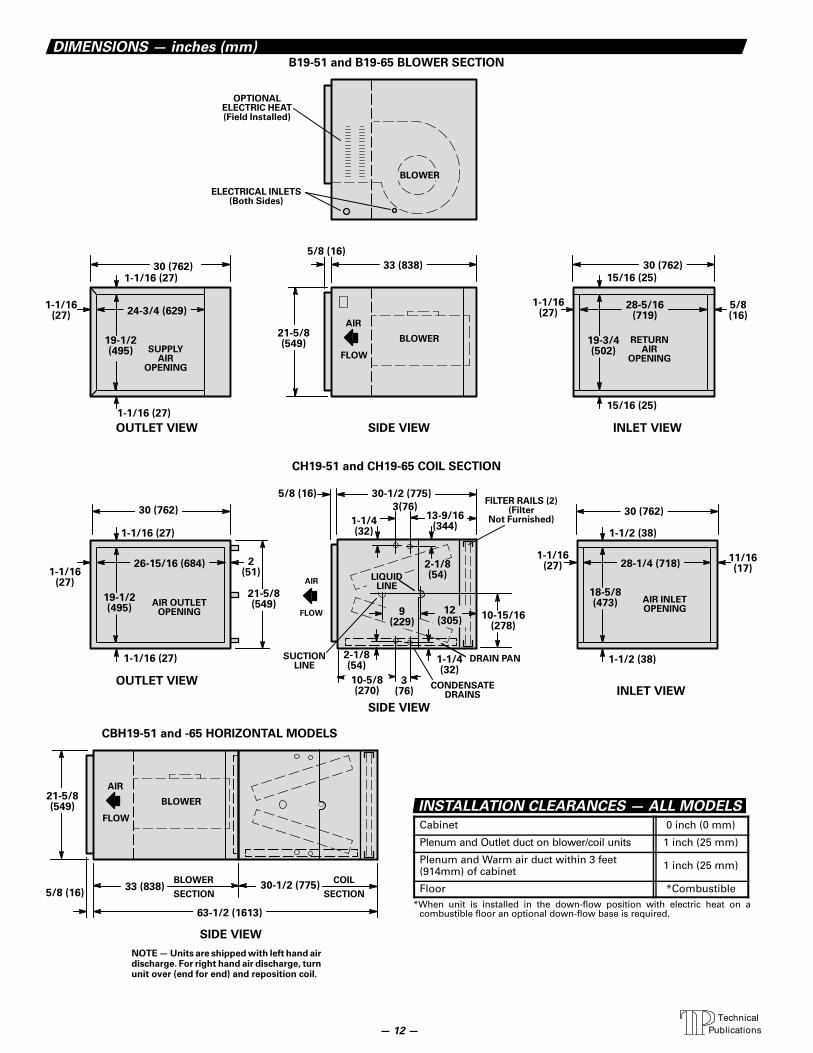
DIMENSIONS — inches (mm)
SUCTIONLINE
RETURNAIR
OPENING
FILTER RAILS (2)(Filter
Not Furnished)
2-1/8(54)
3(76)
10-15/16(278)
CONDENSATEDRAINS
LIQUIDLINE
BLOWER
24-3/4 (629)
19-1/2(495)
AIR INLETOPENING
28-1/4 (718)
18-5/8(473)
26-15/16 (684)
30 (762)15/16 (25)
28-5/16(719)
19-3/4(502)
30 (762)
19-1/2(495)
2(51)
1-1/2 (38)
11/16(17)
1-1/4(32)
1-1/4(32)
30-1/2 (775)
DRAIN PAN
AIR
FLOW
AIR
FLOW
5/8(16)
1-1/16 (27)
SUPPLYAIR
OPENING
AIR OUTLETOPENING
13-9/16(344)
1-1/16 (27)
1-1/16(27)
21-5/8(549)
1-1/16(27)
15/16 (25)
30 (762)
1-1/16(27)
1-1/16 (27)
1-1/16 (27)
5/8 (16)
30 (762)
1-1/16(27)
3(76)
2-1/8(54)
OUTLET VIEW SIDE VIEW INLET VIEW
OUTLET VIEW
SIDE VIEW
INLET VIEW
21-5/8(549)
1-1/2 (38)
5/8 (16)
33 (838)
9(229)
BLOWER
ELECTRICAL INLETS(Both Sides)
OPTIONALELECTRIC HEAT(Field Installed)
12(305)
B19-51 and B19-65 BLOWER SECTION
CH19-51 and CH19-65 COIL SECTION
10-5/8(270)
BLOWER
AIR
FLOW
21-5/8(549)
SIDE VIEW
33 (838) 30-1/2 (775)5/8 (16)
63-1/2 (1613)
BLOWER
SECTION
COIL
SECTION
NOTE — Units are shipped with left hand airdischarge. For right hand air discharge, turnunit over (end for end) and reposition coil.
CBH19-51 and -65 HORIZONTAL MODELS
INSTALLATION CLEARANCES — ALL MODELS
Cabinet 0 inch (0 mm)
Plenum and Outlet duct on blower/coil units 1 inch (25 mm)
Plenum and Warm air duct within 3 feet(914mm) of cabinet 1 inch (25 mm)
Floor *Combustible*When unit is installed in the down-flow position with electric heat on a
combustible floor an optional down-flow base is required.
— 12 —