Embed Size (px)
Citation preview
IEEE TRANSACTIONS ON VEHICULAR TECHNOLOGY, VOL. 58, NO. 8, OCTOBER 2009 4681
Proof of Corollary 1: Denote |n′| = n(t) ⊗ Φ(t). Given (4), thepdf’s of |rc| and |n′| can easily be derived and expressed as
P (|rc|) ≈(2|rc|/M2
)exp
(−|rc|2/M2
)P (|n′|) =
(2|n′|/σ2
n
)exp
(−|n′|2/σ2
n
)respectively. Then, the probability of a missed (false) hit is derived byusing P (|rc|)(P (|n′|)) and the fact that a missed (false) hit happenswhen |rc|(|n′|) is smaller (greater) than ξ. �
ACKNOWLEDGMENT
This work was conducted when the authors were with the WirelessIC System Design Center, HKUST Fok Ying Tung Graduate School,Nansha, China.
REFERENCES
[1] Z. Sahinoglu and S. Gezici, “Ranging in the IEEE 802.15.4a standard,” inProc. IEEE WAMICON, Dec. 2006, pp. 1–5.
[2] R. Cardinali, L. De Nardis, M. G. Di Benedetto, and P. Lombardo, “UWBranging accuracy in high- and low-data-rate applications,” IEEE Trans.Microw. Theory Tech., vol. 54, no. 4, pp. 1865–1875, Jun. 2006.
[3] B. Stein and D. Leeper, “Simulated ranging via UWB in the presence ofmultipath,” IEEE P802.15-05-0296-00-004a, May 2005.
[4] Z. N. Low, J. H. Cheong, C. L. Law, W. T. Ng, and J. Y. Lee, “Pulsedetection algorithm for line-of-sight (LOS) UWB ranging applications,”IEEE Antennas Wireless Propag. Lett., vol. 4, pp. 63–67, 2005.
[5] W. C. Chung and D. S. Ha, “An accurate ultra wideband (UWB)ranging for precision asset location,” in Proc. IEEE ICUWB, Nov. 2003,pp. 389–393.
[6] I. Sahinoglu and Z. Guvenc, “Threshold-based TOA estimationfor impulse radio UWB systems,” in Proc. IEEE ICUWB, Sep. 2005,pp. 420–425.
[7] Z. Guvenc and I. Sahinoglu, “Threshold selection for UWB TOA esti-mation based on kurtosis analysis,” IEEE Commun. Lett., vol. 9, no. 12,pp. 1025–1027, Dec. 2005.
[8] Z. Lei, F. Chin, and Y. S. Kwok, “UWB ranging with energy detectorsusing ternary preamble sequences,” in Proc. IEEE WCNC, Apr. 2006,pp. II.872–II.877.
[9] S. Wu, Q. Zhang, and N. Zhang, “A two-step TOA estimationmethod for IR-UWB ranging systems,” in Proc. IEEE CNSR, May 2007,pp. 302–310.
[10] A. F. Molisch, K. Balakrishnan, D. Cassioli, C. C. Chong, S. Emanmi,A. Fort, F. Karedal, J. Kunisch, H. Schantz, U. Schuster, and K. Siwiak,“IEEE 802.15.4a channel model—Final report,” IEEE P802.15-04-0662-00-004a, Apr. 2005.
[11] WiMedia Alliance, Multi-Band OFDM Physical Layer Specification,Jul. 2005. Rel. 1.1.
[12] J. Y. Lee and R. A. Scholtz, “Ranging in a dense multipath environmentusing an UWB radio link,” IEEE J. Sel. Areas Commun., vol. 20, no. 9,pp. 1677–1683, Dec. 2002.
[13] A. Saleh and R. Valenzuala, “A statistical model for indoor multi-path propagation,” IEEE J. Sel. Areas Commun., vol. SAC-5, no. 2,pp. 128–137, Feb. 1987.
Superposition-Coding-Aided Multiplexed Hybrid ARQScheme for Improved End-to-End Transmission Efficiency
Rong Zhang, Student Member, IEEE, and Lajos Hanzo, Fellow, IEEE
Abstract—In this paper, we propose a novel superposition-coding-aidedmultiplexed Hybrid Automatic Repeat reQuest (HARQ) scheme for thesake of improving both the link layer and the transport control protocol(TCP) layer efficiency. The detailed system design is presented, and thetransmission efficiency metrics of both layers are discussed. Furthermore,the achievable link-layer packet error rate and a range of other transmis-sion efficiency metrics of both layers are quantified. It is demonstrated thatour scheme substantially improves the attainable transmission efficiency ofboth layers and is particularly suitable for delay-sensitive services.
Index Terms—Cross-layer design, Hybrid Automatic Repeat reQuest(HARQ), superposition coding, wireless transport control protocol (TCP).
I. INTRODUCTION
The transport control protocol (TCP) supports reliable end-to-enddata transmission and facilitates congestion control, where the trans-mission frame loss due to link errors is often assumed to be negligiblein wired networks. However, directly transplanting the TCP intowireless applications suffers from link impairments, such as radio linkattenuation, fading, handover, mobility, and cochannel interference.For the sake of avoiding congestion due to physical retransmissionsinduced by channel errors, we may either conceal the effects of thewireless link from the TCP-enabled transmitter or make it aware of thewireless channel effects [1]–[3].
From a cross-layer point of view [4], link-layer approaches such asHybrid Automatic Repeat reQuest (HARQ) [5], which is proposed forthe sake of further improving the robustness against link adaptationinaccuracy due to various implementation impairments, attempt toconceal the channel-induced packet loss events from the TCP-enabledtransmitter by reducing the effects of wireless link errors with theaid of channel coding combined with retransmissions on a promptpacket-based timescale. This solution is appealing as it does not incurthe typical overhead associated with TCP awareness yet obeys theTCP semantics. However, this HARQ-aided approach introduces extradelay due to local link-layer retransmissions, which may potentiallylead to a timeout and, hence, trigger the slow-start phase of the TCPtransmission.
Against this backdrop, in this paper, we aim to improve the overallend-to-end TCP transmission efficiency by reducing the link layer’shop-by-hop HARQ retransmission delay with the aid of our proposedsuperposition-coding-aided multiplexed HARQ (M-HARQ) scheme,which jointly encodes the current new packet to be transmitted andany packets that are about to be retransmitted. In other words, thelink-layer retransmissions are embedded in the next new packet’stransmission, which avoids any potential throughput reduction im-posed by retransmissions, although, naturally, they impose additionalinterference. A similar idea was proposed in [6], which requires a
Manuscript received November 14, 2008; revised February 15, 2009 andMarch 12, 2009. First published March 24, 2009; current version publishedOctober 2, 2009. This work was supported in part by Mobile VCE and in partby the Engineering and Physical Sciences Research Council. The review of thispaper was coordinated by Dr. H. Jiang.
The authors are with the School of Electronics and Computer Science,University of Southampton, SO17 1BJ Southampton, U.K. (e-mail: [email protected]; [email protected]@ecs.soton.ac.uk).
Color versions of one or more of the figures in this paper are available onlineat http://ieeexplore.ieee.org.
Digital Object Identifier 10.1109/TVT.2009.2018982
0018-9545/$26.00 © 2009 IEEE
4682 IEEE TRANSACTIONS ON VEHICULAR TECHNOLOGY, VOL. 58, NO. 8, OCTOBER 2009
specifically designed channel code, and its application is limited totwin-packet joint transmissions. As a benefit, our proposed schemeis capable of jointly and simultaneously transmitting multiple packetsand is equally applicable to both Type-I and -II HARQ techniques.Hence, the advocated technique can seamlessly be integrated withdiverse existing and future systems.
In a nutshell, the contribution of this paper is that we propose anovel M-HARQ scheme, which improves both the link layer and theend-to-end TCP layer transmission efficiency at the cost of a marginallink-layer packet error ratio (PER) performance degradation.
The rest of this paper is organized as follows: In Section II, we pro-vide a general description of the classic HARQ approach. Furthermore,the structure of our proposed M-HARQ arrangement is described,followed by the associated encoding and iterative decoding algorithms.In Section III, the link- and TCP-layer transmission efficiency metricsused are introduced. In Section IV, both the link-layer PER perfor-mance and the transmission efficiency of both the conventional HARQand proposed M-HARQ schemes are evaluated and discussed. Finally,we conclude our discourse in Section V.
II. MULTIPLEXED HARQ
A. Conventional Approach
Being a physical-layer-aware Automatic Repeat reQuest (ARQ)scheme, HARQ combines the cyclic redundancy check (CRC) en-coding function of the link layer with channel coding in the physicallayer. In HARQ, the receiver asks for a packet’s retransmission usingthe reverse-direction channel with the aid of a single-bit Negative-ACKnowledgement (NACK) flag whenever its currently decodedpacket is deemed erroneous based on the decision of the CRC scheme.In general, the retransmissions in ARQ-aided systems can be carriedout in different manners, e.g., using a Type-I packet combing schemeand a Type-II incremental redundancy scheme [7]. In this paper, weelaborate on Type-I HARQ, although our proposed scheme is equallyapplicable to both types. In Type-I HARQ, the same coded packet isused in consecutive retransmissions, allowing the receiver having asufficiently large memory to perform soft combining of the variousreplicas of the packets before decoding. Naturally, each packet isalso individually decodable for a receiver without sufficient memoryto decode each replica of retransmitted packets, although, typically,this results in a residual PER penalty or an increased number ofretransmissions.
Following the aforementioned conceptual introduction, let us nowmathematically describe it. The information arriving from the upperlayer, which is referred to here as a frame, is partitioned into M packetsof equal length Ni, um ∈ {0, 1}Ni , m ∈ [1, M ], where Ni denotesthe information packet length. These packets are protected by thechannel coding function fc,v ∈ Ω = {f1, . . . , fV } of rate rc,v ∈ R ={r1, . . . , rV }, where Ω and R represent a set of predefined discreterate-compatible codes and their corresponding rates. The selectionof a particular code rate is based on the channel quality indicatorcontrolling the link adaptation procedure. The maximum number of re-transmissions is L < M , i.e., a total of (L + 1) transmission attempts.For Type-I HARQ, the same coded packet is repeated L times, i.e.,we have f0
c,v(um) = f lv(um), l ∈ [1, L], where the superscript “0”
stands for the initial transmission. After successfully decoding the mthpacket during the (L + 1)st transmission attempt, the transmission ofthe (m + 1)st packet is activated, as shown in Fig. 1.
B. Proposed Approach
The strategy of transmitting the next new packet only when thesuccessful reception of the current packet was confirmed is highly
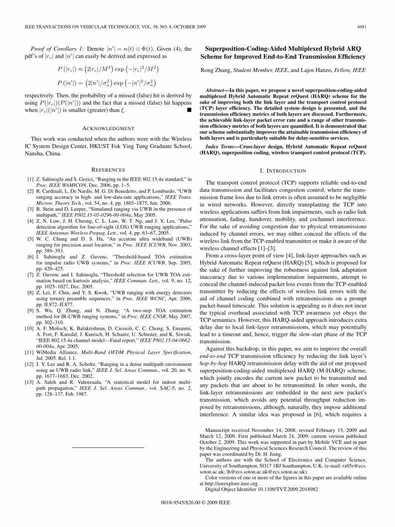
Fig. 1. Classic HARQ and the proposed M-HARQ in conjunctionwith L = 2.
inefficient, which is analogous to the widely recognized drawbackof conventional stop-and-wait ARQ [7]. However, if the receiver iscapable of tolerating a modest amount of additional interference, thenext new packet can simultaneously be transmitted with the retrans-missions of the previous K ∈ [1, L] erroneous packets, as shown inFig. 1. In other words, M new packets are continuously transmitted,whereas the K erroneous packets are transmitted on a virtual channeland appropriately combined with the new packets.
1) Structure: In general, different packets require different num-bers of retransmissions, depending on the instantaneous channelconditions. We consider the worst-case scenario, where each packetexploited the maximum number of retransmissions L, so that we canevaluate the maximum of the PER after L retransmissions. In theworst-case scenario considered and when employing the superpositioncoding scheme to be introduced shortly, the resultant interference ofour M-HARQ arrangement becomes similar to that of the ISI effectsexperienced for transmission over a dispersive channel in the absenceof HARQ transmissions. Analogously, our scheme may be interpretedas generating interpacket interference (IPI), and it may be inferredfrom Fig. 1 that the conventional scheme requires a total of Mr =M(L + 1) packet transmissions, whereas our scheme necessitatesonly Mr = M + L transmissions.
2) Encoding and Decoding: Generally speaking, the joint en-coding function F of the mth transmission can be represented asF (ua1 , . . . ,ua2), where we have
{(a1, a2) = (m, 1), 1 ≤ m < L(a1, a2) = (m, m − L), L ≤ m ≤ M(a1, a2) = (M, m − L), M < m ≤ M + L.
(1)
Although, in principle, specifically designed coding functions may becreated, we opt for the powerful superposition coding concept in thispaper.
F (·) =∑i=a2
2ρiejθif
[fm−i
c,v (ui)]
(2)
where each superimposed packet is referred to as a layer, whereas ρi
and θi ∈ [0, π) denote the layer-specific amplitude and phase rotation,respectively. In this paper, an identical amplitude allocation and uni-form phase rotations are employed for the individual superimposedlayers. The benefit of choosing this particular superposition codingtechnique is that, by opting for this simple linear operation, the specific
IEEE TRANSACTIONS ON VEHICULAR TECHNOLOGY, VOL. 58, NO. 8, OCTOBER 2009 4683
modulation function f(·) and channel coding function fc,v(·) of theindividual layers may be retained.
Our M-HARQ scheme employs iterative multiple packet detection(MPD) and channel decoding (DEC), exchanging extrinsic informa-tion between these two receiver components. The choice of the DECalgorithm depends on the specific channel code employed; however,a host of MPD schemes may be invoked, including the powerful buthigh-complexity maximum-likelihood detection scheme, or we mayopt to employ a low-complexity soft-interference cancellation scheme[8] in this paper.
Remarks: Instead of superposition coding, multiple packets may or-thogonally be multiplexed within a specific transmission attempt with-out imposing any IPI. However, maintaining orthogonality among thepackets requires additional direct-sequence spreading of the original-channel-coded packet, hence resulting in a rate loss. Since orthogonalchannel codes are hard to design, we may exploit the multiplexingcapability that is inherently provided by channel codes having a rateof less than unity by differentiating the layers with the aid of theirunique layer-specific channel codes. Naturally, this is achieved atthe cost of an increased complexity and marginal PER performancedegradation.
III. TRANSMISSION EFFICIENCY METRIC
A general packet-based wireless network is constituted by a wiredlink spanning from a server to an access point (AP) and a wirelesslink from the AP to the mobile terminal. In this section, we discussthe transmission efficiency metrics to be applied for the link and TCPlayers, respectively, which are the effective throughput η and the meanframe arrival rate λ.
The following simplifying assumptions are stipulated: First, whenconsidering the TCP layer’s transmission efficiency, we ignore anypropagation delay over the wireless channel and the feedback delayencountered during the transmission of the link layer’s error-free ACKand NACK indication. Furthermore, for transmission over the block-fading channel considered in this paper, the packet error events areindependently and identically distributed (i.i.d.), resulting in a lowprobability of TCP timeouts due to consecutive packet loss events.Hence, we ignore the so-called slow-start TCP phase and only considerthe congestion-avoidance phase of the widely used TCP Reno [9]. Wealso assume that the M/G/1 queue [9] has a Poissonian arrival processhaving an arrival rate of λ, a general i.i.d. service time duration T , anda single server.
A. Effective Throughput η
Let us define the normalized effective throughput η as the productof the throughput per packet η0 and the total number of packets Mdivided by the total number Mr of transmissions required, yieldingη = η0M/Mr , where the per-packet throughput is given by η0(γb) =r · b[1 − pe(γb)], with r and b being the channel coding rate and thenumber of bits per symbol determined by the modulation schemeemployed, respectively. Furthermore, pe denotes the link layer’s PERas a function of the signal-to-noise ratio per bit, which is denotedby γb. This metric assumes that each packet exhausts all the Lretransmissions for the sake of simplified comparisons.
B. Mean Frame Arrival Rate λ
The normalized effective throughput achieved at the TCP layer maybe measured by the so-called mean transmission frame arrival rateλ encountered, which is determined by the average number of TCPframes N successfully transmitted within the average round-trip time
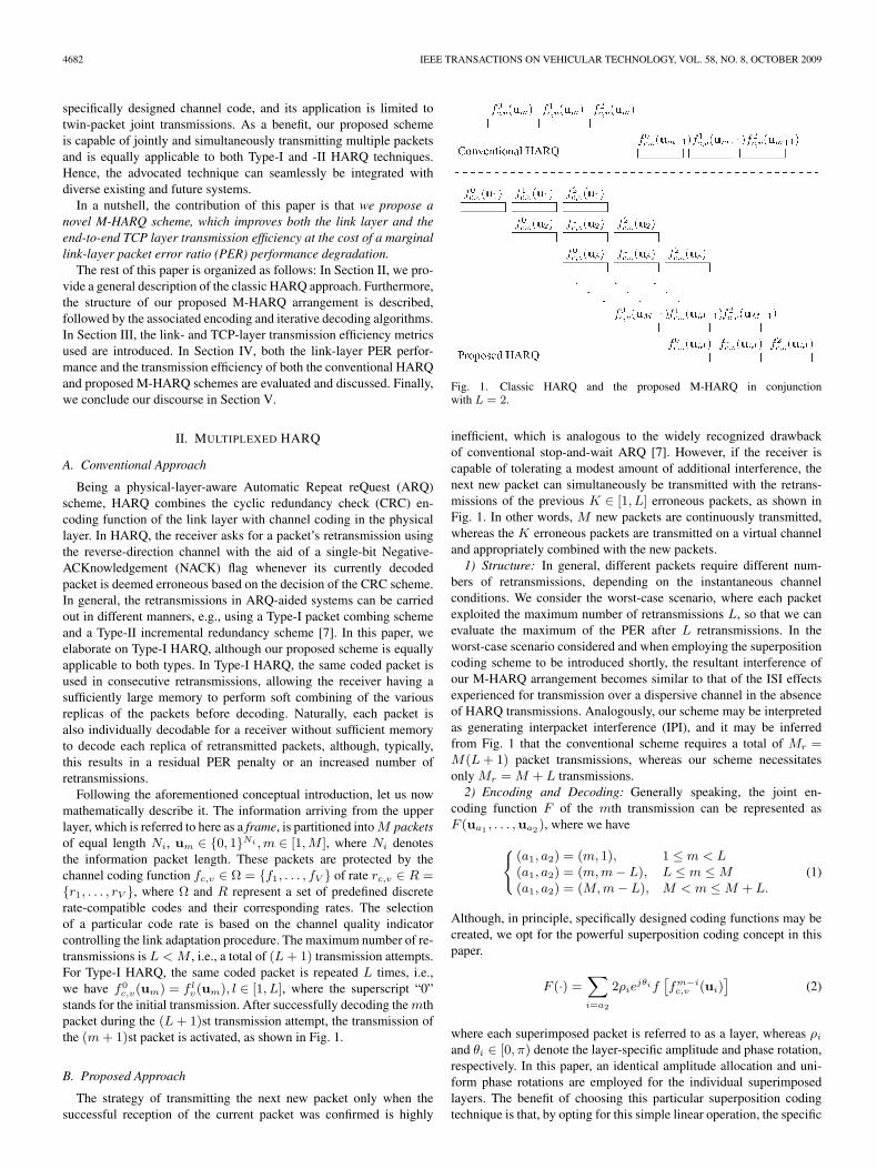
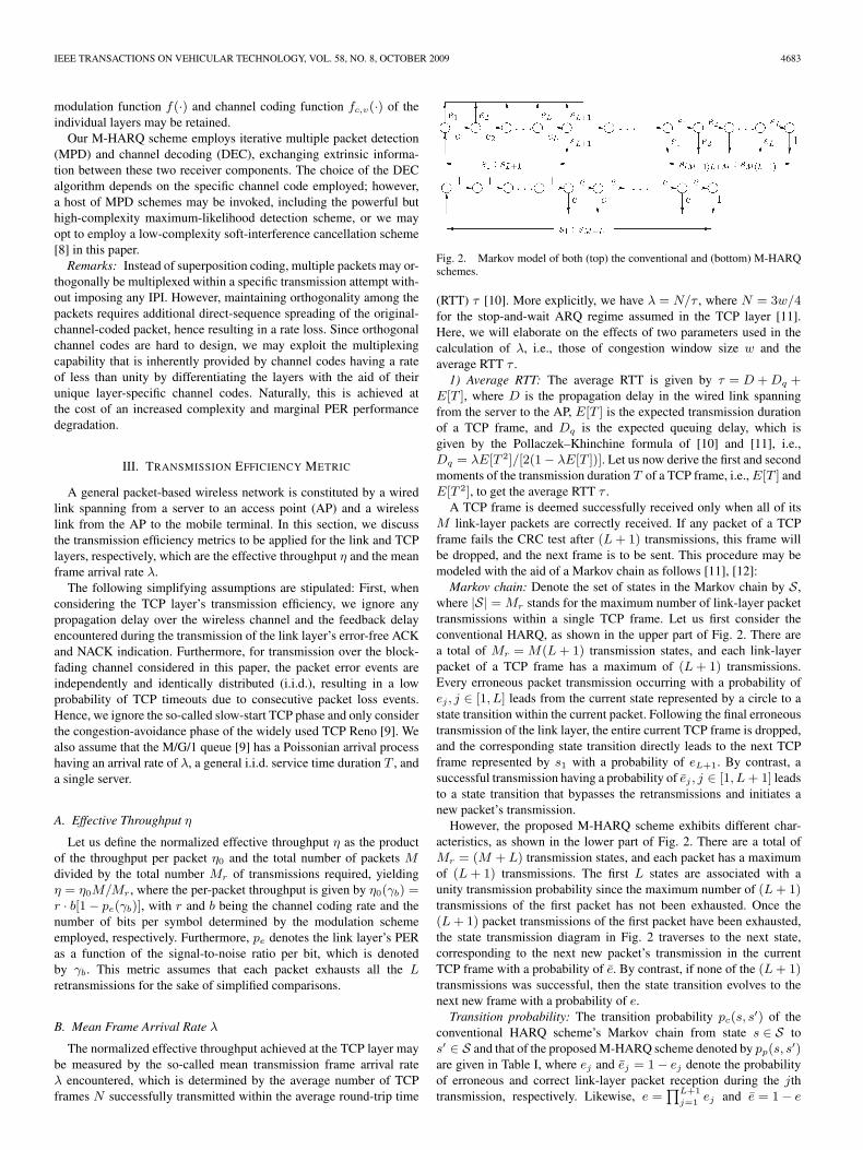
Fig. 2. Markov model of both (top) the conventional and (bottom) M-HARQschemes.
(RTT) τ [10]. More explicitly, we have λ = N/τ , where N = 3w/4for the stop-and-wait ARQ regime assumed in the TCP layer [11].Here, we will elaborate on the effects of two parameters used in thecalculation of λ, i.e., those of congestion window size w and theaverage RTT τ .
1) Average RTT: The average RTT is given by τ = D + Dq +E[T ], where D is the propagation delay in the wired link spanningfrom the server to the AP, E[T ] is the expected transmission durationof a TCP frame, and Dq is the expected queuing delay, which isgiven by the Pollaczek–Khinchine formula of [10] and [11], i.e.,Dq = λE[T 2]/[2(1 − λE[T ])]. Let us now derive the first and secondmoments of the transmission duration T of a TCP frame, i.e., E[T ] andE[T 2], to get the average RTT τ .
A TCP frame is deemed successfully received only when all of itsM link-layer packets are correctly received. If any packet of a TCPframe fails the CRC test after (L + 1) transmissions, this frame willbe dropped, and the next frame is to be sent. This procedure may bemodeled with the aid of a Markov chain as follows [11], [12]:
Markov chain: Denote the set of states in the Markov chain by S,where |S| = Mr stands for the maximum number of link-layer packettransmissions within a single TCP frame. Let us first consider theconventional HARQ, as shown in the upper part of Fig. 2. There area total of Mr = M(L + 1) transmission states, and each link-layerpacket of a TCP frame has a maximum of (L + 1) transmissions.Every erroneous packet transmission occurring with a probability ofej , j ∈ [1, L] leads from the current state represented by a circle to astate transition within the current packet. Following the final erroneoustransmission of the link layer, the entire current TCP frame is dropped,and the corresponding state transition directly leads to the next TCPframe represented by s1 with a probability of eL+1. By contrast, asuccessful transmission having a probability of ej , j ∈ [1, L + 1] leadsto a state transition that bypasses the retransmissions and initiates anew packet’s transmission.
However, the proposed M-HARQ scheme exhibits different char-acteristics, as shown in the lower part of Fig. 2. There are a total ofMr = (M + L) transmission states, and each packet has a maximumof (L + 1) transmissions. The first L states are associated with aunity transmission probability since the maximum number of (L + 1)transmissions of the first packet has not been exhausted. Once the(L + 1) packet transmissions of the first packet have been exhausted,the state transmission diagram in Fig. 2 traverses to the next state,corresponding to the next new packet’s transmission in the currentTCP frame with a probability of e. By contrast, if none of the (L + 1)transmissions was successful, then the state transition evolves to thenext new frame with a probability of e.
Transition probability: The transition probability pc(s, s′) of the
conventional HARQ scheme’s Markov chain from state s ∈ S tos′ ∈ S and that of the proposed M-HARQ scheme denoted by pp(s, s′)are given in Table I, where ej and ej = 1 − ej denote the probabilityof erroneous and correct link-layer packet reception during the jthtransmission, respectively. Likewise, e =
∏L+1
j=1ej and e = 1 − e
4684 IEEE TRANSACTIONS ON VEHICULAR TECHNOLOGY, VOL. 58, NO. 8, OCTOBER 2009
TABLE ITRANSITION PROBABILITY OF THE CONVENTIONAL SCHEME pc(s, s′)
FROM STATE s ∈ S TO s′ ∈ S AND OF THE PROPOSED SCHEME pp(s, s′)
denote the probability of erroneous and correct link-layer packetreception after (L + 1) transmissions, respectively. These transitionprobabilities are then incorporated in the transition probability matrixP of size |S| × |S|.
State probability: State probability vector p hosts the probabilityof each state s ∈ S. The initial state probability p0 is modeled bythe entries p0(s = 1) = 1 and p0
s(s > 1) = 0. The transition stateprobability pq at the qth transition phase is given by pq = p0P, wherewe have q ∈ [min(L + 1, M), |S|], and P is equal to transition proba-bility matrix P, except that the transition to state s = 1 correspondingto the first column of P, i.e., z = P(:, 1), is omitted from P to arriveat P. Finally, steady-state probability ps is obtained by solving thelinear equations ps(s) =
∑s′∈S ps(s′)p(s′, s) subject to constraint∑
s∈S ps(s) = 1.Hence, the first and second moments of T are expressed as E[T ] =∑a1q=a2
pqztq and E[T 2] =∑a1
q=a2pqzt2q , respectively, where we
have a1 = |S| and a2 = min(L + 1, M). Furthermore, tq = qt0stands for the time required for the transmission of q link-layerpackets with each packet’s transmission duration t0 set to unity in thispaper.
2) Congestion Window Size: The congestion window size w in theTCP mechanism is employed to control the frame flow by additivelyincreasing its window size every RTT until either the maximum allow-able buffer size is reached or the congestion is resolved. If so, then thewindow size is halved. Hence, the maximum congestion window sizeis determined by two design parameters, i.e., the affordable buffer sizeand the acceptable frame error rate (FER).
We refer to a buffer-size-limited scenario, when potentially noframe error events are experienced, because the window size of wB
is increased until the buffer is filled. The subsequently arriving TCPframes are then dropped, and the window size of wB is halved inthe interest of getting ready for future window expansion to preventfuture frame-dropping events. Window size wB is given by wB =B + τ/E[T ] + 1 [11], where 1/E[T ] represents the average TCPframe transmission rate. On the other hand, if residual frame errorevents persist after link-layer HARQ retransmissions, window size we
is determined by the residual FER pfe experienced, and we is halved
for the same reason, as previously argued. FER pfe corresponds to the
maximum of (L + 1) link-layer HARQ transmissions, which is givenby pf
e = psze/psz, where ze is equal to the vector of z hosting thetransition probabilities leading to state s = 1 due to failure. Hence,the average number of TCP frames transmitted between two consec-
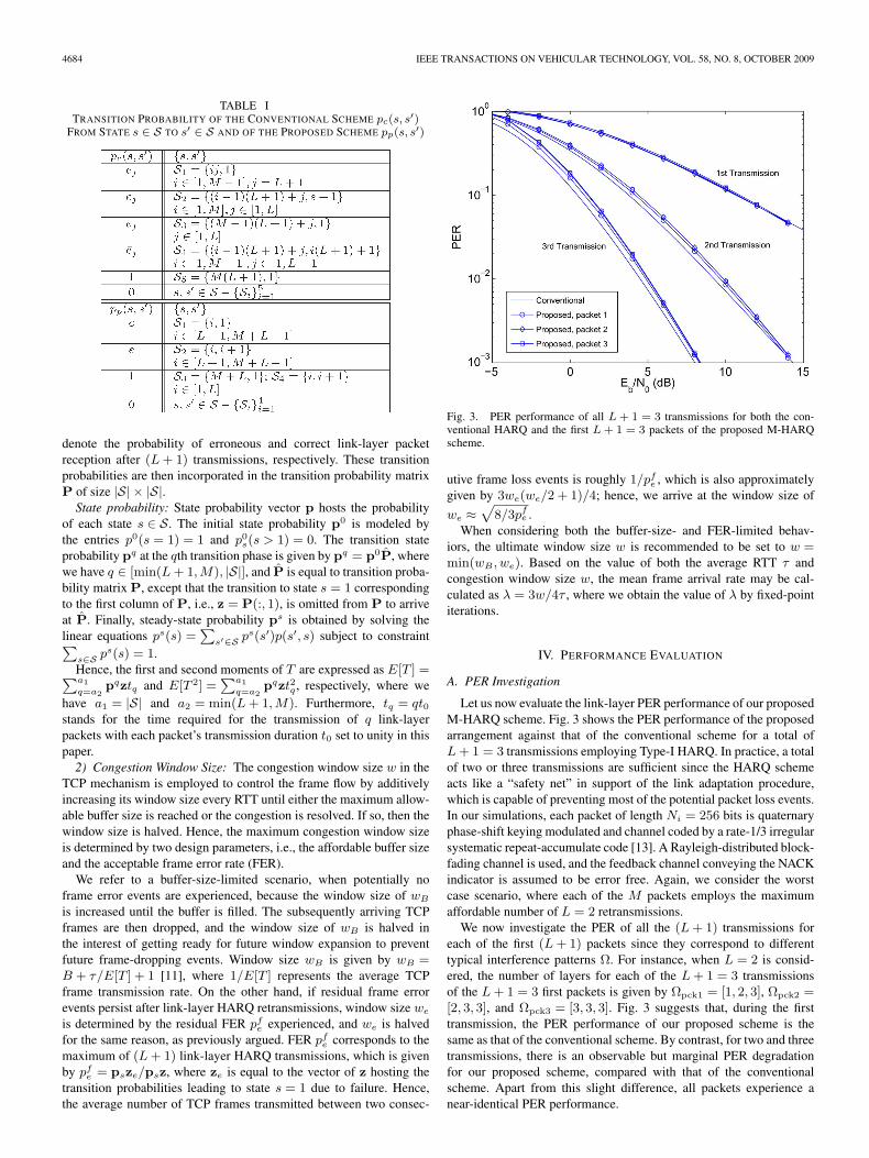
Fig. 3. PER performance of all L + 1 = 3 transmissions for both the con-ventional HARQ and the first L + 1 = 3 packets of the proposed M-HARQscheme.
utive frame loss events is roughly 1/pfe , which is also approximately
given by 3we(we/2 + 1)/4; hence, we arrive at the window size of
we ≈√
8/3pfe .
When considering both the buffer-size- and FER-limited behav-iors, the ultimate window size w is recommended to be set to w =min(wB , we). Based on the value of both the average RTT τ andcongestion window size w, the mean frame arrival rate may be cal-culated as λ = 3w/4τ , where we obtain the value of λ by fixed-pointiterations.
IV. PERFORMANCE EVALUATION
A. PER Investigation
Let us now evaluate the link-layer PER performance of our proposedM-HARQ scheme. Fig. 3 shows the PER performance of the proposedarrangement against that of the conventional scheme for a total ofL + 1 = 3 transmissions employing Type-I HARQ. In practice, a totalof two or three transmissions are sufficient since the HARQ schemeacts like a “safety net” in support of the link adaptation procedure,which is capable of preventing most of the potential packet loss events.In our simulations, each packet of length Ni = 256 bits is quaternaryphase-shift keying modulated and channel coded by a rate-1/3 irregularsystematic repeat-accumulate code [13]. A Rayleigh-distributed block-fading channel is used, and the feedback channel conveying the NACKindicator is assumed to be error free. Again, we consider the worstcase scenario, where each of the M packets employs the maximumaffordable number of L = 2 retransmissions.
We now investigate the PER of all the (L + 1) transmissions foreach of the first (L + 1) packets since they correspond to differenttypical interference patterns Ω. For instance, when L = 2 is consid-ered, the number of layers for each of the L + 1 = 3 transmissionsof the L + 1 = 3 first packets is given by Ωpck1 = [1, 2, 3], Ωpck2 =[2, 3, 3], and Ωpck3 = [3, 3, 3]. Fig. 3 suggests that, during the firsttransmission, the PER performance of our proposed scheme is thesame as that of the conventional scheme. By contrast, for two and threetransmissions, there is an observable but marginal PER degradationfor our proposed scheme, compared with that of the conventionalscheme. Apart from this slight difference, all packets experience anear-identical PER performance.
IEEE TRANSACTIONS ON VEHICULAR TECHNOLOGY, VOL. 58, NO. 8, OCTOBER 2009 4685
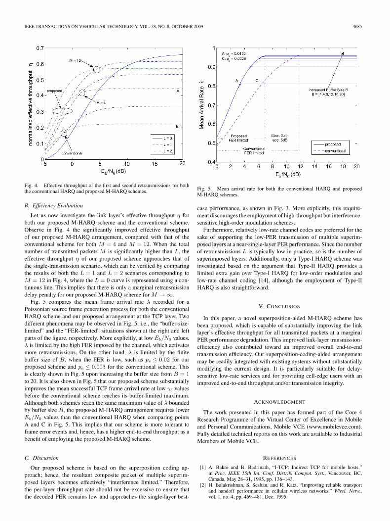
Fig. 4. Effective throughput of the first and second retransmissions for boththe conventional HARQ and proposed M-HARQ schemes.
B. Efficiency Evaluation
Let us now investigate the link layer’s effective throughput η forboth our proposed M-HARQ scheme and the conventional scheme.Observe in Fig. 4 the significantly improved effective throughputof our proposed M-HARQ arrangement, compared with that of theconventional scheme for both M = 4 and M = 12. When the totalnumber of transmitted packets M is significantly higher than L, theeffective throughput η of our proposed scheme approaches that ofthe single-transmission scenario, which can be verified by comparingthe results of both the L = 1 and L = 2 scenarios corresponding toM = 12 in Fig. 4, where the L = 0 curve is represented using a con-tinuous line. This implies that there is only a marginal retransmissiondelay penalty for our proposed M-HARQ scheme for M → ∞.
Fig. 5 compares the mean frame arrival rate λ recorded for aPoissonian source frame generation process for both the conventionalHARQ scheme and our proposed arrangement at the TCP layer. Twodifferent phenomena may be observed in Fig. 5, i.e., the “buffer-size-limited” and the “FER-limited” situations shown at the right and leftparts of the figure, respectively. More explicitly, at low Eb/N0 values,λ is limited by the high FER imposed by the channel, which activatesmore retransmissions. On the other hand, λ is limited by the finitebuffer size of B, when the FER is low, such as pe ≤ 0.02 for ourproposed scheme and pe ≤ 0.003 for the conventional scheme. Thisis clearly shown in Fig. 5 upon increasing the buffer size from B = 1to 20. It is also shown in Fig. 5 that our proposed scheme substantiallyimproves the mean successful TCP frame arrival rate at low γb valuesbefore the conventional scheme reaches its buffer-limited maximum.Although both schemes reach the same maximum value of λ boundedby buffer size B, the proposed M-HARQ arrangement requires lowerEb/N0 values than the conventional HARQ when comparing pointsA and C in Fig. 5. This implies that our scheme is more tolerant toframe error events and, hence, has a higher end-to-end throughput as abenefit of employing the proposed M-HARQ scheme.
C. Discussion
Our proposed scheme is based on the superposition coding ap-proach; hence, the resultant composite packet of multiple superim-posed layers becomes effectively “interference limited.” Therefore,the per-layer throughput rate should not be excessive to ensure thatthe decoded PER remains low and approaches the single-layer best-
Fig. 5. Mean arrival rate for both the conventional HARQ and proposedM-HARQ schemes.
case performance, as shown in Fig. 3. More explicitly, this require-ment discourages the employment of high-throughput but interference-sensitive high-order modulation schemes.
Furthermore, relatively low-rate channel codes are preferred for thesake of supporting the low-PER transmission of multiple superim-posed layers at a near-single-layer PER performance. Since the numberof retransmissions L is typically low in practice, so is the number ofsuperimposed layers. Additionally, only a Type-I HARQ scheme wasinvestigated based on the argument that Type-II HARQ provides alimited extra gain over Type-I HARQ for low-order modulation andlow-rate channel coding [14], although the employment of Type-IIHARQ is also straightforward.
V. CONCLUSION
In this paper, a novel superposition-aided M-HARQ scheme hasbeen proposed, which is capable of substantially improving the linklayer’s effective throughput for all transmitted packets at a marginalPER performance degradation. This improved link-layer transmission-efficiency also contributed toward an improved overall end-to-endtransmission efficiency. Our superposition-coding-aided arrangementmay be readily integrated with existing systems without substantiallymodifying the current design. It is particularly suitable for delay-sensitive low-rate services and for providing cell-edge users with animproved end-to-end throughput and/or transmission integrity.
ACKNOWLEDGMENT
The work presented in this paper has formed part of the Core 4Research Programme of the Virtual Center of Excellence in Mobileand Personal Communications, Mobile VCE (www.mobilevce.com).Fully detailed technical reports on this work are available to IndustrialMembers of Mobile VCE.
REFERENCES
[1] A. Bakre and B. Badrinath, “I-TCP: Indirect TCP for mobile hosts,”in Proc. IEEE 15th Int. Conf. Distrib. Comput. Syst., Vancouver, BC,Canada, May 28–31, 1995, pp. 136–143.
[2] H. Balakrishnan, S. Seshan, and R. Katz, “Improving reliable transportand handoff performance in cellular wireless networks,” Wirel. Netw.,vol. 1, no. 4, pp. 469–481, Dec. 1995.
4686 IEEE TRANSACTIONS ON VEHICULAR TECHNOLOGY, VOL. 58, NO. 8, OCTOBER 2009
[3] R. Caceres and L. Iftode, “Improving the performance of reliable trans-port protocols in mobile computing environments,” IEEE J. Sel. AreasCommun., vol. 13, no. 5, pp. 850–857, Jun. 1995.
[4] S. Shakkottai, T. Rappaport, and P. Karlsson, “Cross-layer design forwireless networks,” IEEE Commun. Mag., vol. 41, no. 10, pp. 74–80,Oct. 2003.
[5] L. Hanzo, J. Blogh, and S. Ni, 3G, HSDPA, HSUPA and IntelligentFDD Versus TDD Networking: Smart Antennas and Adaptive Modulation.Piscataway, NJ: IEEE Press, 2008.
[6] C. Hausl and A. Chindapol, “Hybrid ARQ with cross-packet channelcoding,” IEEE Commun. Lett., vol. 11, no. 5, pp. 434–436, May 2007.
[7] S. Lin and D. J. Costello, Error Control Coding: Fundamentals andApplications, 2nd ed. Englewood Cliffs, NJ: Prentice–Hall, 2005.
[8] X. Wang and V. Poor, “Iterative (turbo) soft interference cancellationand decoding for coded CDMA,” IEEE Trans. Commun., vol. 47, no. 7,pp. 1046–1061, Jul. 1999.
[9] W. Stevens, TCP/IP Illustrated, vol. I. Reading, MA: Addison-Wesley,1994.
[10] L. Kleinrock, Queueing Systems, vol. I/II. New York: Wiley, 1976.[11] Q. Huang, S. Chan, L. Ping, and M. Zukerman, “Improving wireless TCP
throughput by a novel TCM-based hybrid ARQ,” IEEE Trans. WirelessCommun., vol. 6, no. 7, pp. 2476–2485, Jul. 2007.
[12] C. F. Chiasserini and M. Meo, “Improving TCP over wireless throughadaptive link layer setting,” in Proc. IEEE GLOBECOM, San Antonio,TX, Nov. 25–29, 2001, pp. 1766–1770.
[13] J. Jin, A. Khandekar, and R. J. McEliece, “Irregular repeat-accumulate codes,” in Proc. 2nd Int. Conf. Turbo Codes, Brest, France,Sep. 4–7, 2000, pp. 125–127.
[14] P. Frenger, S. Parkvall, and E. Dahlman, “Performance comparisonof HARQ with Chase combining and incremental redundancy forHSDPA,” in Proc. IEEE VTC—Fall, Atlantic City, NJ, Oct. 7–11, 2001,pp. 1829–1833.
Multi-Invariance ESPRIT-Based Blind DOA Estimationfor MC-CDMA With an Antenna Array
Xiaofei Zhang, Xin Gao, and Dazhuan Xu
Abstract—In this paper, we address the problem of direction-of-arrival (DOA) estimation for a multicarrier code-division multiple-access(MC-CDMA) system with an antenna array. We reconstruct the receivedsignal to form a data model with a multi-invariance property, and then, amulti-invariance estimation of signal parameters via rotational invariancetechnique (ESPRIT) algorithm for DOA estimation is proposed. Thisalgorithm has improved DOA estimation performance and identified moreDOAs compared with an ESPRIT algorithm. Moreover, our algorithmenables DOA estimation of a large number of impinging waves. Simulationresults illustrate the performance of this algorithm.
Index Terms—Antenna array, direction-of-arrival (DOA) estimation,estimation of signal parameters via rotational invariance techniques(ESPRIT), multicarrier code-division multiple access (MC-CDMA),multi-invariance.
Manuscript received April 28, 2008; revised October 5, 2008,December 15, 2008, and February 18, 2009. First published April 10,2009; current version published October 2, 2009. This work was supported inpart by China National Science Foundation (NSF) under Grant 60801052, bythe Ph.D. Programs Foundation of the Ministry of Education of China underGrant 200802871056, and by Jiangsu NSF under Grant BK2007192. Thereview of this paper was coordinated by Dr. T. Taniguchi.
The authors are with the Department of Electronic Engineering, NanjingUniversity of Aeronautics and Astronautics, Nanjing 210016, China (e-mail:[email protected]).
Digital Object Identifier 10.1109/TVT.2009.2020596
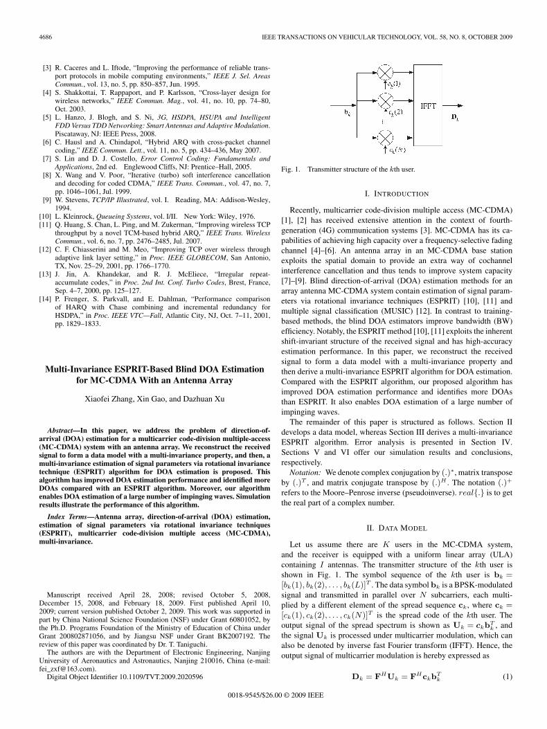
Fig. 1. Transmitter structure of the kth user.
I. INTRODUCTION
Recently, multicarrier code-division multiple access (MC-CDMA)[1], [2] has received extensive attention in the context of fourth-generation (4G) communication systems [3]. MC-CDMA has its ca-pabilities of achieving high capacity over a frequency-selective fadingchannel [4]–[6]. An antenna array in an MC-CDMA base stationexploits the spatial domain to provide an extra way of cochannelinterference cancellation and thus tends to improve system capacity[7]–[9]. Blind direction-of-arrival (DOA) estimation methods for anarray antenna MC-CDMA system contain estimation of signal param-eters via rotational invariance techniques (ESPRIT) [10], [11] andmultiple signal classification (MUSIC) [12]. In contrast to training-based methods, the blind DOA estimators improve bandwidth (BW)efficiency. Notably, the ESPRIT method [10], [11] exploits the inherentshift-invariant structure of the received signal and has high-accuracyestimation performance. In this paper, we reconstruct the receivedsignal to form a data model with a multi-invariance property andthen derive a multi-invariance ESPRIT algorithm for DOA estimation.Compared with the ESPRIT algorithm, our proposed algorithm hasimproved DOA estimation performance and identifies more DOAsthan ESPRIT. It also enables DOA estimation of a large number ofimpinging waves.
The remainder of this paper is structured as follows. Section IIdevelops a data model, whereas Section III derives a multi-invarianceESPRIT algorithm. Error analysis is presented in Section IV.Sections V and VI offer our simulation results and conclusions,respectively.
Notation: We denote complex conjugation by (.)∗, matrix transposeby (.)T , and matrix conjugate transpose by (.)H . The notation (.)+
refers to the Moore–Penrose inverse (pseudoinverse). real{.} is to getthe real part of a complex number.
II. DATA MODEL
Let us assume there are K users in the MC-CDMA system,and the receiver is equipped with a uniform linear array (ULA)containing I antennas. The transmitter structure of the kth user isshown in Fig. 1. The symbol sequence of the kth user is bk =[bk(1), bk(2), . . . , bk(L)]T . The data symbol bk is a BPSK-modulatedsignal and transmitted in parallel over N subcarriers, each multi-plied by a different element of the spread sequence ck, where ck =[ck(1), ck(2), . . . , ck(N)]T is the spread code of the kth user. Theoutput signal of the spread spectrum is shown as Uk = ckb
Tk , and
the signal Uk is processed under multicarrier modulation, which canalso be denoted by inverse fast Fourier transform (IFFT). Hence, theoutput signal of multicarrier modulation is hereby expressed as
Dk = FHUk = FHckbTk (1)
0018-9545/$26.00 © 2009 IEEE