Embed Size (px)
Citation preview
Hitachi Microcomputer Support Software
SuperH RISC Engine
Assembler
User’s Manual
ADE-702-090C
Rev. 4.011/4/98Hitachi, Ltd.McS-Setsu
Cautions
1. Hitachi neither warrants nor grants licenses of any rights of Hitachi’s or any third party’spatent, copyright, trademark, or other intellectual property rights for information contained inthis document. Hitachi bears no responsibility for problems that may arise with third party’srights, including intellectual property rights, in connection with use of the informationcontained in this document.
2. Products and product specifications may be subject to change without notice. Confirm that youhave received the latest product standards or specifications before final design, purchase oruse.
3. Hitachi makes every attempt to ensure that its products are of high quality and reliability.However, contact Hitachi’s sales office before using the product in an application thatdemands especially high quality and reliability or where its failure or malfunction may directlythreaten human life or cause risk of bodily injury, such as aerospace, aeronautics, nuclearpower, combustion control, transportation, traffic, safety equipment or medical equipment forlife support.
4. Design your application so that the product is used within the ranges guaranteed by Hitachiparticularly for maximum rating, operating supply voltage range, heat radiation characteristics,installation conditions and other characteristics. Hitachi bears no responsibility for failure ordamage when used beyond the guaranteed ranges. Even within the guaranteed ranges,consider normally foreseeable failure rates or failure modes in semiconductor devices andemploy systemic measures such as fail-safes, so that the equipment incorporating Hitachiproduct does not cause bodily injury, fire or other consequential damage due to operation ofthe Hitachi product.
5. This product is not designed to be radiation resistant.
6. No one is permitted to reproduce or duplicate, in any form, the whole or part of this documentwithout written approval from Hitachi.
7. Contact Hitachi’s sales office for any questions regarding this document or Hitachisemiconductor products.
Rev. 4.0, 09/98, page v of 15
Preface
This manual describes the SuperH RISC Engine Assembler (hereafter referred to as theassembler), which supports development of programs for Hitachi SuperH RISC engine family(hereafter referred to as microprocessor).
This manual is organized as follows:
Overview: Gives an overview of the functions of the assembler.Programmer's Guide: Describes the assembly language syntax and programming techniques.User's Guide: Describes the use (invocation) of the assembler program itself and the
command line options.Appendix: Describes assembler limitations and error messages.
Read this manual and fully understand its mechanisim before use of the assembler.
For information concerning the related hardware and software, read the corresponding manualsand understand their mechanisims before use.
Rev. 4.0, 09/98, page vi of 15
Notes:
• The following symbols have special meanings in this manual.
<item>: <specification item>
∆: Blank space(s) or tab(s)
%: The OS prompt (indicates the input waiting state)
(RET): Press the Return (Enter) key.
... : The preceding item can be repeated.
[ ]: The enclosed item is optional (i.e., can be omitted.)
• Numbers are written as follows in this manual.
Binary: A prefix of “ B' ” is used.
Octal: A prefix of “ Q' ” is used.
Decimal: A prefix of “ D' ” is used.
Hexadecimal: A prefix of “ H' ” is used.
However, when there is no specification, the number without a prefix is decimal.
Windows95 and WindowsNT are registered trademarks of Microsoft Corporation.UNIX is a registered trademark in the United States and other countries, licensed exclusivelythrough X/Open Company Limited.SPARC is a CPU and workstation administered by SPARC International, Inc.HP9000/700 series is a trademark of Hewlett-Packard Company.PC-9800 series is a trademark of NEC Corporation.IBM PC is a registered trademark of International Business Machines Corporation.
Rev. 4.0, 09/98, page vii of 15
Contents
Overview
Section 1 Overview........................................................................................................... 3
Section 2 Relationships between the Software Development SupportTools................................................................................................................... 5
Programmer’s Guide
Section 1 Program Elements.......................................................................................... 111.1 Source Statements ............................................................................................................. 11
1.1.1 Source Statement Structure .................................................................................. 111.1.2 Coding of Source Statements ............................................................................... 131.1.3 Coding of Source Statements across Multiple Lines............................................ 15
1.2 Reserved Words ................................................................................................................ 161.3 Symbols............................................................................................................................. 16
1.3.1 Functions of Symbols........................................................................................... 161.3.2 Coding of Symbols............................................................................................... 18
1.4 Constants ........................................................................................................................... 191.4.1 Integer Constants.................................................................................................. 191.4.2 Character Constants.............................................................................................. 201.4.3 Floating-Point Constants ...................................................................................... 211.4.4 Fixed-Point Constants .......................................................................................... 26
1.5 Location Counter............................................................................................................... 291.6 Expressions........................................................................................................................ 31
1.6.1 Elements of Expression........................................................................................ 311.6.2 Operation Precedence........................................................................................... 331.6.3 Detailed Description on Operation....................................................................... 361.6.4 Notes on Expressions ........................................................................................... 39
1.7 Character Strings ............................................................................................................... 401.8 Local Label........................................................................................................................ 42
1.8.1 Local Label Functions.......................................................................................... 421.8.2 Description Method of Local Label ..................................................................... 431.8.3 Scope of Local Labels .......................................................................................... 43
Section 2 Basic Programming Knowledge................................................................. 452.1 Sections ............................................................................................................................. 45
2.1.1 Section Types by Usage ....................................................................................... 452.1.2 Absolute Address Sections and Relative Address Sections.................................. 50
Rev. 4.0, 09/98, page viii of 15
2.2 Absolute and Relative Values ........................................................................................... 522.2.1 Absolute Values ................................................................................................... 522.2.2 Relative Values .................................................................................................... 52
2.3 Symbol Definition and Reference ..................................................................................... 532.3.1 Symbol Definition ................................................................................................ 532.3.2 Symbol Reference ................................................................................................ 55
2.4 Separate Assembly ............................................................................................................ 572.4.1 Separate Assembly ............................................................................................... 572.4.2 Declaration of Export Symbols and Import Symbols........................................... 58
Section 3 Executable Instructions................................................................................. 613.1 Overview of Executable Instructions ................................................................................ 613.2 Notes on Executable Instructions ...................................................................................... 67
3.2.1 Notes on the Operation Size................................................................................. 673.2.2 Notes on Delayed Branch Instructions ................................................................. 843.2.3 Notes on Address Calculations............................................................................. 86
Section 4 DSP Instructions............................................................................................. 914.1 Program Contents.............................................................................................................. 91
4.1.1 Source Statements ................................................................................................ 914.1.2 Parallel Operation Instructions............................................................................. 924.1.3 Data Move Instructions ........................................................................................ 934.1.4 Coding of Source Statements Across Multiple Lines........................................... 94
4.2 DSP Instructions................................................................................................................ 954.2.1 DSP Operation Instructions.................................................................................. 954.2.2 Data Move Instructions ........................................................................................ 99
Section 5 Assembler Directives..................................................................................... 1035.1 Overview of the Assembler Directives.............................................................................. 1035.2 Assembler Directive Reference......................................................................................... 105
5.2.1 Target CPU Assembler Directive......................................................................... 105.CPU .................................................................................................................... 106
5.2.2 Section and Location Counter Assembler Directives........................................... 108.SECTION ........................................................................................................... 109.ORG.................................................................................................................... 114.ALIGN ............................................................................................................... 116
5.2.3 Symbol Handling Assembler Directives .............................................................. 118.EQU .................................................................................................................... 119.ASSIGN ............................................................................................................. 121.REG .................................................................................................................... 123.FREG.................................................................................................................. 125
5.2.4 Data and Data Area Reservation Assembler Directives ....................................... 127.DATA .................................................................................................................. 128
Rev. 4.0, 09/98, page ix of 15
.DATAB ............................................................................................................... 130
.SDATA ............................................................................................................... 133
.SDATAB............................................................................................................. 135
.SDATAC............................................................................................................. 138
.SDATAZ ............................................................................................................. 140
.FDATA ............................................................................................................... 142
.FDATAB ............................................................................................................. 144
.XDATA ............................................................................................................... 147
.RES .................................................................................................................... 149
.SRES.................................................................................................................. 152
.SRESC ............................................................................................................... 154
.SRESZ ............................................................................................................... 156
.FRES .................................................................................................................. 1585.2.5 Export and Import Assembler Directives ............................................................. 160
.EXPORT............................................................................................................. 161
.IMPORT ............................................................................................................. 163
.GLOBAL............................................................................................................. 1655.2.6 Object Module Assembler Directives .................................................................. 167
.OUTPUT............................................................................................................. 168
.DEBUG............................................................................................................... 171
.ENDIAN ............................................................................................................. 173
.LINE .................................................................................................................. 1765.2.7 Assemble Listing Assembler Directives............................................................... 178
.PRINT ............................................................................................................... 179
.LIST .................................................................................................................. 181
.FORM.................................................................................................................. 185
.HEADING........................................................................................................... 187
.PAGE.................................................................................................................. 189
.SPACE ............................................................................................................... 1915.2.8 Other Assembler Directives ................................................................................. 193
.PROGRAM........................................................................................................... 194
.RADIX ............................................................................................................... 196
.END .................................................................................................................... 198
Section 6 File Inclusion Function................................................................................. 201.INCLUDE ........................................................................................................... 202
Section 7 Conditional Assembly Function................................................................. 2057.1 Overview of the Conditional Assembly Function ............................................................. 205
7.1.1 Preprocessor variables.......................................................................................... 2057.1.2 Replacement Symbols .......................................................................................... 2067.1.3 Conditional Assembly .......................................................................................... 2077.1.4 Iterated Expansion................................................................................................ 209
Rev. 4.0, 09/98, page x of 15
7.1.5 Conditional Iterated Expansion ............................................................................ 2107.2 Conditional Assembly Directives...................................................................................... 211
.ASSIGNA ........................................................................................................... 212
.ASSIGNC........................................................................................................... 215
.DEFINE ............................................................................................................. 217
.AIF, .AELIF, .AELSE, .AENDI ........................................................... 219
.AIFDEF, .AELSE, .AENDI ....................................................................... 222
.AREPEAT, .AENDR ........................................................................................ 224
.AWHILE, .AENDW .......................................................................................... 226
.AERROR............................................................................................................. 229
.EXITM ............................................................................................................... 231
.ALIMIT ............................................................................................................. 233
Section 8 Macro Function............................................................................................... 2358.1 Overview of the Macro Function ...................................................................................... 2358.2 Macro Function Directives................................................................................................ 237
.MACRO, .ENDM............................................................................................... 238
.EXITM ............................................................................................................... 2418.3 Macro Body....................................................................................................................... 2438.4 Macro Call......................................................................................................................... 2478.5 Character String Manipulation Functions.......................................................................... 249
.LEN .................................................................................................................... 250
.INSTR ............................................................................................................... 252
.SUBSTR............................................................................................................. 254
Section 9 Automatic Literal Pool Generation Function......................................... 2579.1 Overview of Automatic Literal Pool Generation............................................................... 2579.2 Extended Instructions Related to Automatic Literal Pool Generation............................... 2589.3 Size Mode for Automatic Literal Pool Generation............................................................ 2589.4 Literal Pool Output............................................................................................................ 260
9.4.1 Literal Pool Output after Unconditional Branch .................................................. 2619.4.2 Literal Pool Output to the .POOL Location ......................................................... 262
9.5 Literal Sharing................................................................................................................... 2649.6 Literal Pool Output Suppression ....................................................................................... 2669.7 Notes on Automatic Literal Pool Output........................................................................... 267
Section 10 Automatic Repeat Loop Generation Function....................................... 27110.1 Overview of Automatic Repeat Loop Generation Function.............................................. 27110.2 Extended Instructions of Automatic Repeat Loop Generation Function........................... 27210.3 REPEAT Description ........................................................................................................ 27210.4 Coding Examples .............................................................................................................. 27410.5 Notes on the REPEAT Extended Instruction .................................................................... 277
Rev. 4.0, 09/98, page xi of 15
User’s Guide
Section 1 Executing the Assembler.............................................................................. 2811.1 Command Line Format ..................................................................................................... 2811.2 File Specification Format .................................................................................................. 2821.3 SHCPU Environment Variable.......................................................................................... 283
Section 2 Command Line Options................................................................................ 2852.1 Overview of Command Line Options ............................................................................... 2852.2 Command Line Option Reference..................................................................................... 287
2.2.1 Target CPU Command Line Option..................................................................... 287–CPU.................................................................................................................... 288
2.2.2 Object Module Command Line Options .............................................................. 289–OBJECT, –NOOBJECT................................................................................... 290–DEBUG, –NODEBUG........................................................................................ 292–ENDIAN............................................................................................................. 294
2.2.3 Assembly Listing Command Line Options .......................................................... 295–LIST, –NOLIST ............................................................................................ 296–SOURCE, –NOSOURCE................................................................................... 298–CROSS_REFERENCE, –NOCROSS_REFERENCE........................................ 300–SECTION, –NOSECTION.............................................................................. 302–SHOW, –NOSHOW............................................................................................ 304–LINES ............................................................................................................... 306–COLUMNS........................................................................................................... 307
2.2.4 File Inclusion Function Command Line Option................................................... 308–INCLUDE........................................................................................................... 309
2.2.5 Conditional Assembly Command Line Options................................................... 310–ASSIGNA........................................................................................................... 311–ASSIGNC........................................................................................................... 313–DEFINE ............................................................................................................. 315
2.2.6 Assembler Execution Command Line Option...................................................... 316–EXPAND............................................................................................................. 317–ABORT............................................................................................................... 318
2.2.7 Japanese Character Description Command Line Options .................................... 319–SJIS .................................................................................................................. 320–EUC.................................................................................................................... 321–OUTCODE........................................................................................................... 322
2.2.8 Automatic Literal Pool Generation Command Line Option................................. 323–AUTO_LITERAL............................................................................................... 324
2.2.9 Command Line Input Command Line Option...................................................... 326–SUBCOMMAND................................................................................................... 327
Rev. 4.0, 09/98, page xii of 15
2.2.10 Floating-Point Data Command Line Options....................................................... 329–ROUND............................................................................................................... 330–DENORMALIZE................................................................................................. 332
Appendix
Appendix A Limitations and Notes on Programming............................................... 337
Appendix B Sample Program........................................................................................... 338B.1 Sample Program Specifications......................................................................................... 338B.2 Coding Example................................................................................................................ 339
Appendix C Assemble Listing Output Example......................................................... 341C.1 Source Program Listing..................................................................................................... 342C.2 Cross-Reference Listing .................................................................................................... 344C.3 Section Information Listing............................................................................................... 345
Appendix D Error Messages............................................................................................. 346D.1 Error Types........................................................................................................................ 346D.2 Error Message Tables........................................................................................................349
Appendix E Differences from Version 3.1................................................................... 371E.1 CPU .................................................................................................................................. 371E.2 Object Format.................................................................................................................... 371E.3 Constants ........................................................................................................................... 372E.4 Changed Assembler Directives ......................................................................................... 372E.5 Added Command Line Options......................................................................................... 372
Appendix F ASCII Code Table........................................................................................ 374
Rev. 4.0, 09/98, page xiii of 15
Figures
OverviewFigure 1-1 Function of the Assembler...................................................................................... 4Figure 2-1 Relationships between the Software Development Support Tools ......................... 6
Programmer’s GuideFigure 2-1 Memory Reservation of Common Section ............................................................. 47Figure 2-2 Data Structure Example Using Dummy Section .................................................... 49Figure 2-3 Meaning of the Terms Forward and Backward ...................................................... 55Figure 2-4 Meaning of the Term External................................................................................ 55Figure 2-5 Relationship between the Changed Range of the Source Program and
the Range of the Program that must be Reassembled............................................. 57Figure 3-1 Address Calculation Example (Normal Case) ........................................................ 86Figure 3-2 Address Calculation Example (When the Value of PC Differs Due to a Branch).. 87Figure 3-3 Address Calculation Example (When Microprocessor Corrects
the Value of PC) .................................................................................................... 88Figure 3-4 Address Calculation Example (When Microprocessor Does Not Correct
the Value of PC) ..................................................................................................... 88
AppendixFigure C-1 Source Program Listing Output Example............................................................... 342Figure C-2 Cross-Reference Listing Output Example .............................................................. 344Figure C-3 Section Information Listing Output Example......................................................... 345
Rev. 4.0, 09/98, page xiv of 15
Tables
Programmer’s GuideTable 1-1 Floating-Point Data Types...................................................................................... 22Table 1-2 Data Types and Numerical Value Ranges (Absolute Value).................................. 23Table 1-3 Data Format Size .................................................................................................... 24Table 1-4 Floating-Point Representation for Each Data Type ................................................ 25Table 1-5 Operators ................................................................................................................ 31Table 1-6 Operator Precedence and Association Rules .......................................................... 33Table 1-7 Even/Odd Operations.............................................................................................. 38Table 3-1 Addressing Modes .................................................................................................. 62Table 3-2 Allowed Displacement Values................................................................................ 64Table 3-3 Allowed Immediate Values .................................................................................... 66Table 3-4 SH-1 Executable Instruction and Operation Size Combinations ........................... 67Table 3-5 SH-2 Executable Instruction and Operation Size Combinations ........................... 73Table 3-6 SH-2E Executable Instruction and Operation Size Combinations ......................... 74Table 3-7 SH-3 Executable Instruction and Operation Size Combinations ........................... 76Table 3-8 SH-3E Executable Instruction and Operation Size Combinations ......................... 78Table 3-9 SH-4 Executable Instruction and Operation Size Combinations ........................... 80Table 3-10 SH-DSP, SH3-DSP Executable Instruction and Operation Size Combinations .... 83Table 3-11 Relationship between Delayed Branch Instructions and Delay Slot Instructions ... 85Table 4-1 DSP Instructions in Mnemonic............................................................................... 95Table 4-2 Addressing Modes for DSP Operation Instructions................................................ 95Table 4-3 Registers that Can Be Specified in DSP Register Direct Addressing Mode........... 96Table 4-4 Ranges of Immediate Data...................................................................................... 96Table 4-5 DSP Operation Instructions .................................................................................... 98Table 4-6 Data Move Instructions in Mnemonic .................................................................... 99Table 4-7 Addressing Modes of Data Move Instructions ....................................................... 100Table 4-8 Registers that Can Be Specified in Addressing Modes for Data Move
Instructions ............................................................................................................. 101Table 4-9 Data Move Instructions........................................................................................... 102Table 5-1 Assembler Directives.............................................................................................. 103Table 9-1 Extended Instructions and Expanded Results ......................................................... 258Table 9-2 Data Move Instructions and Size Mode.................................................................. 258Table 9-3 Instructions Selected in Size Selection Mode......................................................... 259Table 10-1 Repeat Loop Instructions and Address Setting ....................................................... 271Table 10-2 Extended Instructions and Expanded Results ......................................................... 272
User’s GuideTable 2-1 Command Line Options.......................................................................................... 285
Rev. 4.0, 09/98, page xv of 15
AppendixTable A-1 Limitations and Notes on Programming................................................................. 337Table D-1 Command Error Messages...................................................................................... 349Table D-2 Source Program Error Messages............................................................................. 350Table D-3 Source Program Warning Messages ....................................................................... 362Table D-4 Fatal Error Messages .............................................................................................. 368Table E-1 Changed Assembler Directives and Statements...................................................... 372Table E-2 Added Command Line Options .............................................................................. 372Table F-1 ASCII Code Table .................................................................................................. 374

Overview
Rev. 4.0, 09/98, page 3 of 391
Section 1 Overview
The assembler converts source programs written in assembly language into a format that can behandled by microprocessors, and outputs the result as an object module. Also, the results of theassembly processing are output as an assemble listing.
This assembler provides the following functions to support efficient program development:
• Assembler directives
Give the assembler various instructions.
• File inclusion function
Includes files into a source file.
• Conditional assembly function
Selects source statements to be assembled or repeats assembly according to a specifiedcondition.
• Macro function
Gives a name to a sequence of statements and defines it as one instruction.
• Automatic literal pool generation function
Interprets data transfer instructions MOV.W #imm, MOV.L #imm, and MOVA #imm that arenot provided by the SuperH RISC engine family as extended instructions and expands theminto microprocessor executable instructions and constant data (literals).
• Automatic repeat loop generation function
Interprets instruction REPEAT that is not provided by the SH-DSP as an extended instructionand expands it into SH-DSP repeat loop instructions (LDRS, LDRE, and SETRC) that controlthe repeat loop characteristic of the SH-DSP.
Rev. 4.0, 09/98, page 4 of 391
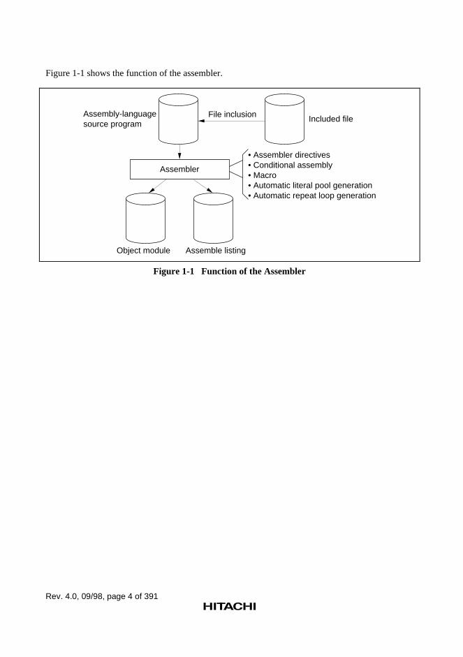
Figure 1-1 shows the function of the assembler.
Assembly-language source program
Assembler
Object module Assemble listing
File inclusion Included file
• Assembler directives• Conditional assembly• Macro • Automatic literal pool generation• Automatic repeat loop generation
Figure 1-1 Function of the Assembler
Rev. 4.0, 09/98, page 5 of 391
Section 2 Relationships between the SoftwareDevelopment Support Tools
In addition to the assembler, software development support tools, such as the C/C++ compiler,linkage editor, librarian, object converter, and simulator/debugger are available for the SuperHRISC engine family.
These tools assist in the efficient development of application software.
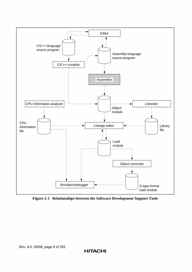
Figure 2-1 shows the relationships between the software development support tools.
Rev. 4.0, 09/98, page 6 of 391
C/C++-language source program
Editor
C/C++ compiler
Assembly-language source program
Object module
Librarian
Linkage editor Library file
Load module
Object converter
Simulator/debugger S-type-format load module
Assembler
CPU information analyzer
CPUinformationfile
Figure 2-1 Relationships between the Software Development Support Tools
Rev. 4.0, 09/98, page 7 of 391
Supplement:
Use a general purpose editor (a text editor) to edit source programs.
The C/C++ compiler converts programs written in the C/C++ language into either object modulesor assembly-language source programs.
The librarian converts object modules and relocatable load modules into library files. Werecommend handling processing that is common to multiple programs as a library file. (This hasseveral advantages, including allowing modules to be easily managed.)
The linkage editor links together object modules and library files to produce load modules(executable programs).
The object converter converts load modules into the S-type format. (The S-type format is astandard load module format.)
The simulator/debugger assists debugging microprocessor software.
Load modules created by this development support system can be input to several types ofemulator. (Emulators are systems for debugging microprocessor system hardware and software.)Also, S-type-format load modules can be input into most EPROM programmers.
Programmer’s Guide
Rev. 4.0, 09/98, page 11 of 391
Section 1 Program Elements
1.1 Source Statements
?If source programs are compared to natural language writing, a source statement will correspondto "a sentence." The "words" that make up a source statement are reserved words and symbols.
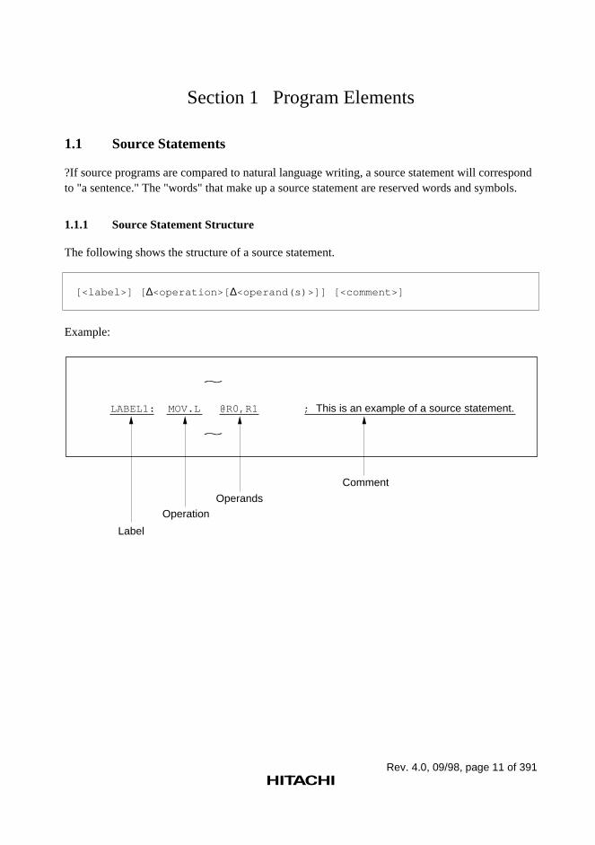
1.1.1 Source Statement Structure
The following shows the structure of a source statement.
[<label>] [ ∆<operation>[ ∆<operand(s)>]] [<comment>]
Example:
~
LABEL1: MOV.L @R0,R1 ; This is an example of a source statement.
~
Label
OperationOperands
Comment
Rev. 4.0, 09/98, page 12 of 391
(1) Label
A symbol or a local symbol is written as a tag attached to a source statement.
A symbol is a name defined by the programmer.
(2) Operation
The mnemonic of an executable instruction, an extended instruction, a DSP instruction, anassembler directive, or a directive statement is written as the operation.
Executable instructions must be microprocessor instructions.
Extended instructions are instructions that are expanded into executable instructions and constantdata (literals) or several executable instructions. For details, refer to Programmer's Guide, 9,"Automatic Literal Pool Generation Function" and 10, "Automatic Repeat Loop GenerationFunction".
DSP instructions are instructions that control the DSP of the SH-DSP microprocessor. For details,refer to Programmer's Guide, 4, "DSP Instructions."
Assembler directives are instructions that give directions to the assembler.
Directive statements are used for file inclusion, conditional assembly, and macro functions. Fordetails on each of these functions, refer to Programmer's Guide, 6, "File Inclusion Function", 7,"Conditional Assembly Function", or 8, "Macro Function".
(3) Operand
The object(s) of the operation's execution are written as the operand.
The number of operands and their types are determined by the operation. There are also operationswhich do not require any operands.
(4) Comment
Notes or explanations that make the program easier to understand are written as the comment.
Rev. 4.0, 09/98, page 13 of 391
1.1.2 Coding of Source Statements
Source statements are written using ASCII characters. Character strings and comments can includeJapanese kana and kanji characters (shift JIS code or EUC code).
In principle, a single statement must be written on a single line. The maximum length of a line is255 bytes.
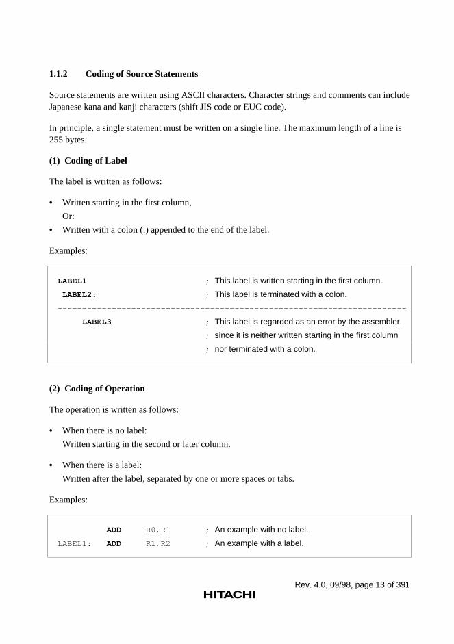
(1) Coding of Label
The label is written as follows:
• Written starting in the first column,
Or:
• Written with a colon (:) appended to the end of the label. Examples:
LABEL1 ; This label is written starting in the first column.
LABEL2: ; This label is terminated with a colon.
-----------------------------------------------------------------------
LABEL3 ; This label is regarded as an error by the assembler,
; since it is neither written starting in the first column
; nor terminated with a colon.
(2) Coding of Operation
The operation is written as follows:
• When there is no label:
Written starting in the second or later column.
• When there is a label:
Written after the label, separated by one or more spaces or tabs. Examples:
ADD R0,R1 ; An example with no label.
LABEL1: ADD R1,R2 ; An example with a label.
Rev. 4.0, 09/98, page 14 of 391
CAUTION!
Since white spaces and tabs are ASCII characters, each space or tab requires a byte of storage.
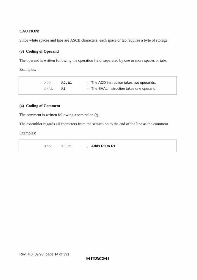
(3) Coding of Operand
The operand is written following the operation field, separated by one or more spaces or tabs.
Examples:
ADD R0,R1 ; The ADD instruction takes two operands.
SHAL R1 ; The SHAL instruction takes one operand.
(4) Coding of Comment
The comment is written following a semicolon (;).
The assembler regards all characters from the semicolon to the end of the line as the comment.
Examples:
ADD R0,R1 ; Adds R0 to R1.
Rev. 4.0, 09/98, page 15 of 391
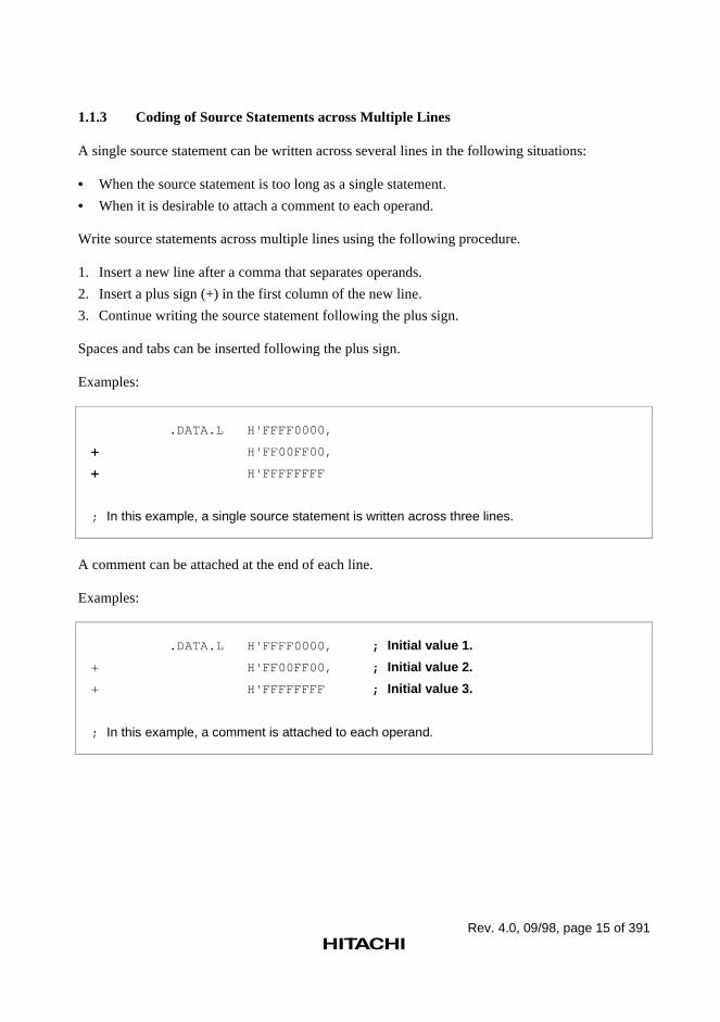
1.1.3 Coding of Source Statements across Multiple Lines
A single source statement can be written across several lines in the following situations:
• When the source statement is too long as a single statement.
• When it is desirable to attach a comment to each operand. Write source statements across multiple lines using the following procedure.
1. Insert a new line after a comma that separates operands.
2. Insert a plus sign (+) in the first column of the new line.
3. Continue writing the source statement following the plus sign. Spaces and tabs can be inserted following the plus sign.
Examples:
.DATA.L H'FFFF0000,
+ H'FF00FF00,
+ H'FFFFFFFF
; In this example, a single source statement is written across three lines.
A comment can be attached at the end of each line.
Examples:
.DATA.L H'FFFF0000, ; Initial value 1.
+ H'FF00FF00, ; Initial value 2.
+ H'FFFFFFFF ; Initial value 3.
; In this example, a comment is attached to each operand.
Rev. 4.0, 09/98, page 16 of 391
1.2 Reserved Words
Reserved words are names that the assembler reserves as symbols with special meanings.
Register names, operators, and the location counter are used as reserved words. Reserved wordsare different depending on the CPU type. Refer to the programming manual of the CPU used, fordetails.
Reserved words must not be used as symbols.
• Register names: R0 to R15, FR0 to FR15, DR0 to DR14 (only even values), XD0 to XD14(only even values), FV0 to FV12 (only multiples of four), R0_BANK to R7_BANK, SP, SR,GBR, VBR, MACH, MACL, PR, PC, SSR, SPC, FPUL, FPSCR, MOD, RE, RS, DSR, A0,A0G, A1, A1G, M0, M1, X0, X1, Y0, Y1, XMTRX, DBR, SGR
• Operators: STARTOF, SIZEOF, HIGH, LOW, HWORD, LWORD, $EVEN, $ODD,$EVEN2, $ODD2
• Location counter ($) Note: R15 and SP indicate the same register.
Reference:
Operators → Programmer's Guide, 1.6.1, "Expression Elements"Location counter→ Programmer's Guide, 1.5, "Location Counter"CPU type → Programmer's Guide, 5.2.1, "Target CPU Assembler Directive", .CPU
→ User's Guide, 1.3, "SHCPU Environment Variable"→ User's Guide, 2.2.1, "Target CPU Command Line Option", –CPU
Symbols → Programmer's Guide, 1.3, "Symbols"
1.3 Symbols
1.3.1 Functions of Symbols
Symbols are names defined by the programmer, and perform the following functions.
• Address symbols: Express data storage and branch destination addresses.
• Constant symbols: Express constants.
• Aliases of register names: Express general registers and floating-point registers.
• Section names Express section names. * Note: A section is a part of the program, and the linkage editor regards it as a unit of processing.
The following shows examples of symbol usage.
Rev. 4.0, 09/98, page 17 of 391
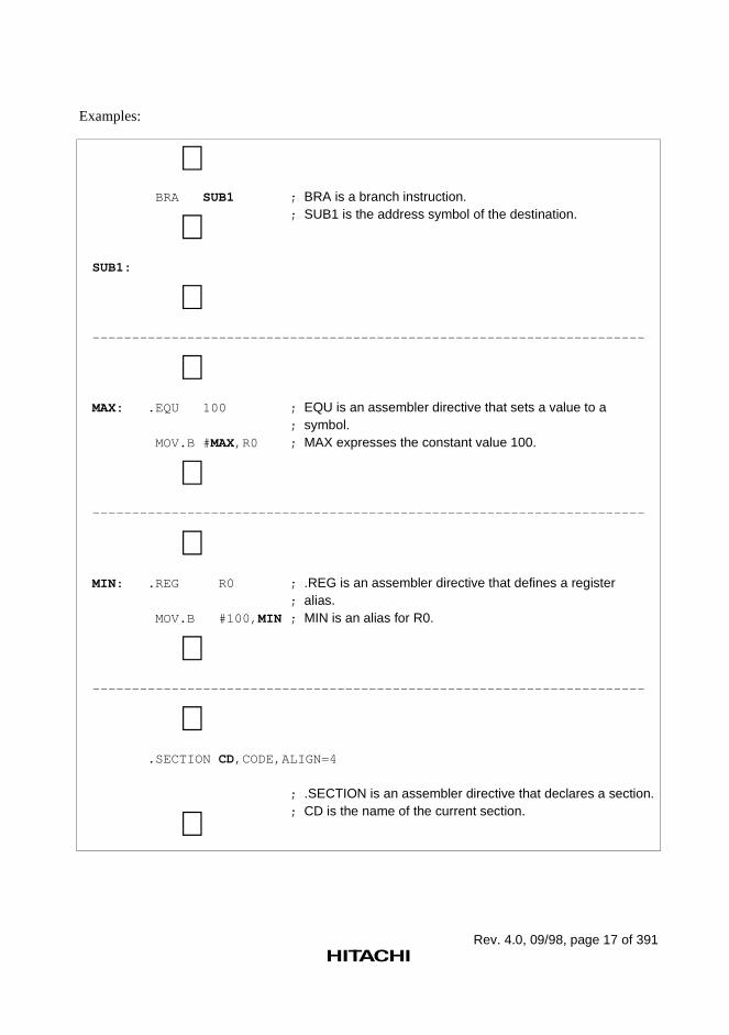
Examples:
∼ BRA SUB1 ; BRA is a branch instruction. ; SUB1 is the address symbol of the destination. ∼ SUB1:
∼ ---------------------------------------------------------------------- ∼ MAX: .EQU 100 ; EQU is an assembler directive that sets a value to a ; symbol. MOV.B # MAX,R0 ; MAX expresses the constant value 100. ∼ ---------------------------------------------------------------------- ∼ MIN: .REG R0 ; .REG is an assembler directive that defines a register ; alias. MOV.B #100, MIN ; MIN is an alias for R0. ∼ ---------------------------------------------------------------------- ∼ .SECTION CD,CODE,ALIGN=4
; .SECTION is an assembler directive that declares a section. ; CD is the name of the current section. ∼
Rev. 4.0, 09/98, page 18 of 391
1.3.2 Coding of Symbols
(1) Available Characters
The following ASCII characters can be used.
• Alphabetical uppercase and lowercase letters (A to Z, a to z)
• Numbers (0 to 9)
• Underscore (_)
• Dollar sign ($) The assembler distinguishes uppercase letters from lowercase letters in symbols.
(2) First Character in a Symbol
The first character in a symbol must be one of the following.
• Alphabetical uppercase and lowercase letters (A to Z, a to z)
• Underscore (_)
• Dollar sign ($) CAUTION!
The dollar sign character used alone is a reserved word that expresses the location counter.
Reference:
Reserved words → Programmer's Guide, 1.2, "Reserved Words"
(3) Maximum Length of a Symbol
A symbol may contain up to 251 characters.
The assembler ignores any characters after the first 251.
(4) Names that Cannot Be Used as Symbols
Reserved words cannot be used as symbols. The following names must not be used because theyare used as internal symbols by the assembler.
_$$nnnnn (n is a number from 0 to 9.)
Note: Internal symbols are necessary for assembler internal processing. Internal symbols are notoutput to assemble listings or object modules.
Rev. 4.0, 09/98, page 19 of 391
1.4 Constants
1.4.1 Integer Constants
Integer constants are expressed with a prefix that indicates the radix.
The radix indicator prefix is a notation that indicates the radix of the constant.
• Binary numbers: The radix indicator “B'” plus a binary constant.
• Octal numbers: The radix indicator “Q'” plus an octal constant.
• Decimal numbers: The radix indicator “D'” plus a decimal constant.
• Hexadecimal numbers: The radix indicator “H'” plus a hexadecimal constant. The assembler does not distinguish uppercase letters from lowercase letters in the radix indicator.
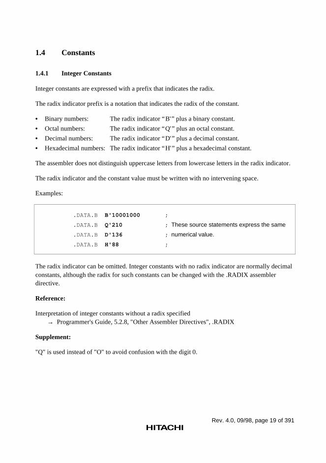
The radix indicator and the constant value must be written with no intervening space.
Examples:
.DATA.B B'10001000 ;
.DATA.B Q'210 ; These source statements express the same
.DATA.B D'136 ; numerical value.
.DATA.B H'88 ;
The radix indicator can be omitted. Integer constants with no radix indicator are normally decimalconstants, although the radix for such constants can be changed with the .RADIX assemblerdirective.
Reference:
Interpretation of integer constants without a radix specified → Programmer's Guide, 5.2.8, "Other Assembler Directives", .RADIX
Supplement:
"Q" is used instead of "O" to avoid confusion with the digit 0.
Rev. 4.0, 09/98, page 20 of 391
1.4.2 Character Constants
Character constants are considered to be constants that represent ASCII codes.
Character constants are written by enclosing up to four ASCII characters in double quotationmarks.
The following ASCII characters can be used in character constants.
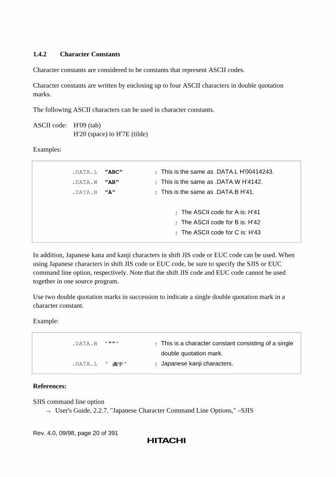
ASCII code: H'09 (tab)H'20 (space) to H'7E (tilde)
Examples:
.DATA.L "ABC" ; This is the same as .DATA.L H'00414243.
.DATA.W "AB" ; This is the same as .DATA.W H'4142.
.DATA.B "A" ; This is the same as .DATA.B H'41.
; The ASCII code for A is: H'41
; The ASCII code for B is: H'42
; The ASCII code for C is: H'43
In addition, Japanese kana and kanji characters in shift JIS code or EUC code can be used. Whenusing Japanese characters in shift JIS code or EUC code, be sure to specify the SJIS or EUCcommand line option, respectively. Note that the shift JIS code and EUC code cannot be usedtogether in one source program.
Use two double quotation marks in succession to indicate a single double quotation mark in acharacter constant.
Example:
.DATA.B " "" " ; This is a character constant consisting of a single
double quotation mark.
.DATA.L " " ; Japanese kanji characters.
References:
SJIS command line option→ User's Guide, 2.2.7, "Japanese Character Command Line Options," –SJIS
Rev. 4.0, 09/98, page 21 of 391
EUC command line option→ User's Guide, 2.2.7, "Japanese Character Command Line Options," –EUC
1.4.3 Floating-Point Constants
Floating-point constants can be specified as operands in assembler directives for reservingfloating-point constants.
Floating-Point Constant Representation:
Floating-point constants can be represented in decimal and hexadecimal.
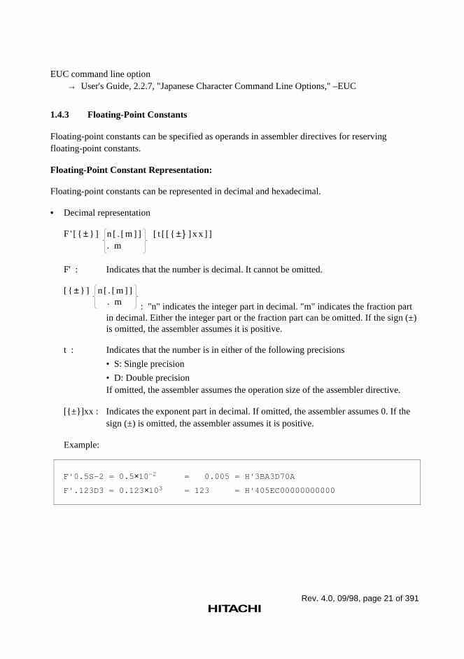
• Decimal representation
F ' [ { ± } ] n [ . [ m ] ] [ t [ [ { ± } ] x x ] ]. m
F' : Indicates that the number is decimal. It cannot be omitted.
[ { ± } ] n [ . [ m ] ]. m : "n" indicates the integer part in decimal. "m" indicates the fraction partin decimal. Either the integer part or the fraction part can be omitted. If the sign (±)is omitted, the assembler assumes it is positive.
t : Indicates that the number is in either of the following precisions
• S: Single precision
• D: Double precisionIf omitted, the assembler assumes the operation size of the assembler directive.
[{±}]xx : Indicates the exponent part in decimal. If omitted, the assembler assumes 0. If thesign (±) is omitted, the assembler assumes it is positive.
Example:
F'0.5S–2 = 0.5 ×10–2 = 0.005 = H'3BA3D70A
F'.123D3 = 0.123 ×103 = 123 = H'405EC00000000000
Rev. 4.0, 09/98, page 22 of 391
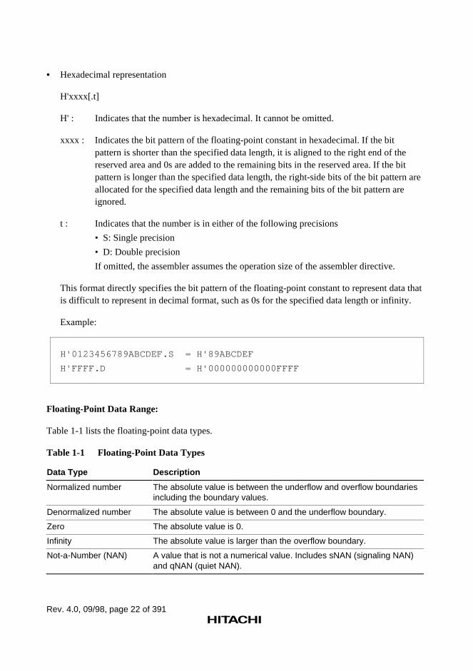
• Hexadecimal representation
H'xxxx[.t]
H' : Indicates that the number is hexadecimal. It cannot be omitted.
xxxx : Indicates the bit pattern of the floating-point constant in hexadecimal. If the bitpattern is shorter than the specified data length, it is aligned to the right end of thereserved area and 0s are added to the remaining bits in the reserved area. If the bitpattern is longer than the specified data length, the right-side bits of the bit pattern areallocated for the specified data length and the remaining bits of the bit pattern areignored.
t : Indicates that the number is in either of the following precisions
• S: Single precision
• D: Double precision
If omitted, the assembler assumes the operation size of the assembler directive.
This format directly specifies the bit pattern of the floating-point constant to represent data thatis difficult to represent in decimal format, such as 0s for the specified data length or infinity.
Example:
H'0123456789ABCDEF.S = H'89ABCDEF
H'FFFF.D = H'000000000000FFFF
Floating-Point Data Range:
Table 1-1 lists the floating-point data types.
Table 1-1 Floating-Point Data Types
Data Type Description
Normalized number The absolute value is between the underflow and overflow boundariesincluding the boundary values.
Denormalized number The absolute value is between 0 and the underflow boundary.
Zero The absolute value is 0.
Infinity The absolute value is larger than the overflow boundary.
Not-a-Number (NAN) A value that is not a numerical value. Includes sNAN (signaling NAN)and qNAN (quiet NAN).
Rev. 4.0, 09/98, page 23 of 391
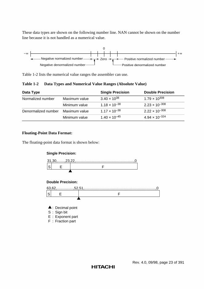
These data types are shown on the following number line. NAN cannot be shown on the numberline because it is not handled as a numerical value.
Negative normalized number Zero Positive normalized number
0
+∞−∞
Negative denormalized number Positive denormalized number
x x x x
Table 1-2 lists the numerical value ranges the assembler can use.
Table 1-2 Data Types and Numerical Value Ranges (Absolute Value)
Data Type Single Precision Double Precision
Normalized number Maximum value 3.40 × 1038 1.79 × 10308
Minimum value 1.18 × 10–38 2.23 × 10–308
Denormalized number Maximum value 1.17 × 10–38 2.22 × 10–308
Minimum value 1.40 × 10–45 4.94 × 10–324
Floating-Point Data Format:
The floating-point data format is shown below:
: Decimal pointS : Sign bitE : Exponent partF : Fraction part
31,30,.......,23,22,.........................................................,0
S E F
63,62,................,52,51,......................................................................,0
S E F
Single Precision:
Double Precision:
Rev. 4.0, 09/98, page 24 of 391
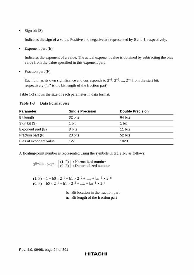
• Sign bit (S)
Indicates the sign of a value. Positive and negative are represented by 0 and 1, respectively.
• Exponent part (E)
Indicates the exponent of a value. The actual exponent value is obtained by subtracting the biasvalue from the value specified in this exponent part.
• Fraction part (F)
Each bit has its own significance and corresponds to 2–1, 2–2, ..., 2–n from the start bit,respectively ("n" is the bit length of the fraction part).
Table 1-3 shows the size of each parameter in data format.
Table 1-3 Data Format Size
Parameter Single Precision Double Precision
Bit length 32 bits 64 bits
Sign bit (S) 1 bit 1 bit
Exponent part (E) 8 bits 11 bits
Fraction part (F) 23 bits 52 bits
Bias of exponent value 127 1023
A floating-point number is represented using the symbols in table 1-3 as follows:
(1. F)(0. F)
: Normalized number: Denormalized number2E−bias . ( 1)s .
(1. F) = 1 + b0 × 2–1 + b1 × 2–2 + ..... + bn–1 × 2–n
(0. F) = b0 × 2–1 + b1 × 2–2 + ..... + bn–1 × 2–n
b: Bit location in the fraction partn: Bit length of the fraction part
Rev. 4.0, 09/98, page 25 of 391
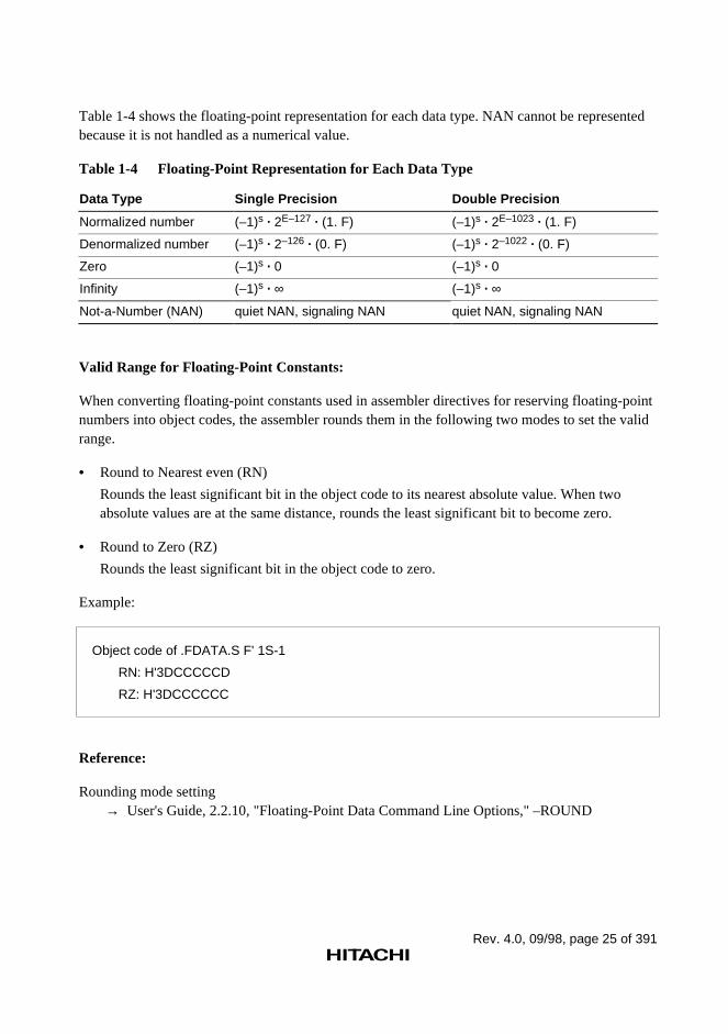
Table 1-4 shows the floating-point representation for each data type. NAN cannot be representedbecause it is not handled as a numerical value.
Table 1-4 Floating-Point Representation for Each Data Type
Data Type Single Precision Double Precision
Normalized number (–1)s · 2E–127 · (1. F) (–1)s · 2E–1023 · (1. F)
Denormalized number (–1)s · 2–126 · (0. F) (–1)s · 2–1022 · (0. F)
Zero (–1)s · 0 (–1)s · 0
Infinity (–1)s · ∞ (–1)s · ∞
Not-a-Number (NAN) quiet NAN, signaling NAN quiet NAN, signaling NAN
Valid Range for Floating-Point Constants:
When converting floating-point constants used in assembler directives for reserving floating-pointnumbers into object codes, the assembler rounds them in the following two modes to set the validrange.
• Round to Nearest even (RN)
Rounds the least significant bit in the object code to its nearest absolute value. When twoabsolute values are at the same distance, rounds the least significant bit to become zero.
• Round to Zero (RZ)
Rounds the least significant bit in the object code to zero. Example:
Object code of .FDATA.S F' 1S-1
RN: H'3DCCCCCD
RZ: H'3DCCCCCC
Reference:
Rounding mode setting→ User's Guide, 2.2.10, "Floating-Point Data Command Line Options," –ROUND
Rev. 4.0, 09/98, page 26 of 391
Handling Denormalized Numbers:
The assembler handles denormalized numbers differently depending on the CPU type. In a CPUthat does not handle denormalized numbers, if a value in the denormalized number range is used,warning number 841 occurs and the object code is output as zero.
In a CPU that handles denormalized numbers, if a value in the denormalized number range is used,warning number 842 occurs and the object code is output in denormalized numbers.
How to handle denormalized numbers can be switched with the DENORMALIZE command lineoption.
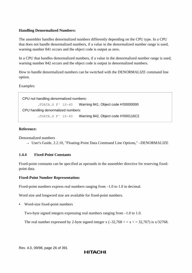
Examples:
CPU not handling denormalized numbers:
.FDATA.S F' 1S-40 Warning 841, Object code H'00000000
CPU handling denormalized numbers:
.FDATA.S F' 1S-40 Warning 842, Object code H'000116C2
Reference:
Denormalized numbers→ User's Guide, 2.2.10, "Floating-Point Data Command Line Options," –DENORMALIZE
1.4.4 Fixed-Point Constants
Fixed-point constants can be specified as operands in the assembler directive for reserving fixed-point data.
Fixed-Point Number Representation:
Fixed-point numbers express real numbers ranging from –1.0 to 1.0 in decimal.
Word size and longword size are available for fixed-point numbers.
• Word-size fixed-point numbers
Two-byte signed integers expressing real numbers ranging from –1.0 to 1.0.
The real number expressed by 2-byte signed integer x (–32,768 < = x < = 32,767) is x/32768.
Rev. 4.0, 09/98, page 27 of 391
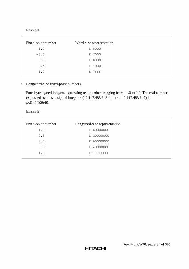
Example:
Fixed-point number Word-size representation
–1.0 H'8000
–0.5 H'C000
0.0 H'0000
0.5 H'4000
1.0 H'7FFF
• Longword-size fixed-point numbers
Four-byte signed integers expressing real numbers ranging from –1.0 to 1.0. The real numberexpressed by 4-byte signed integer x (–2,147,483,648 < = x < = 2,147,483,647) isx/2147483648.
Example:
Fixed-point number Longword-size representation
–1.0 H'80000000
–0.5 H'C0000000
0.0 H'00000000
0.5 H'40000000
1.0 H'7FFFFFFF
Rev. 4.0, 09/98, page 28 of 391
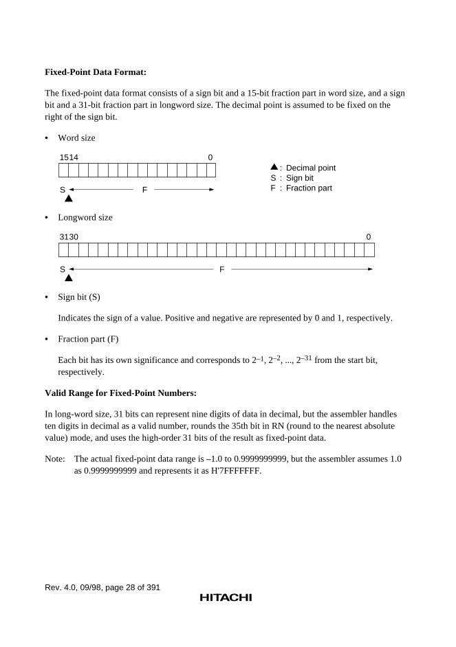
Fixed-Point Data Format:
The fixed-point data format consists of a sign bit and a 15-bit fraction part in word size, and a signbit and a 31-bit fraction part in longword size. The decimal point is assumed to be fixed on theright of the sign bit.
• Word size
FS
1514 0: Decimal point
S : Sign bitF : Fraction part
• Longword size
FS
3130 0
• Sign bit (S)
Indicates the sign of a value. Positive and negative are represented by 0 and 1, respectively.
• Fraction part (F)
Each bit has its own significance and corresponds to 2–1, 2–2, ..., 2–31 from the start bit,respectively.
Valid Range for Fixed-Point Numbers:
In long-word size, 31 bits can represent nine digits of data in decimal, but the assembler handlesten digits in decimal as a valid number, rounds the 35th bit in RN (round to the nearest absolutevalue) mode, and uses the high-order 31 bits of the result as fixed-point data.
Note: The actual fixed-point data range is –1.0 to 0.9999999999, but the assembler assumes 1.0as 0.9999999999 and represents it as H'7FFFFFFF.
Rev. 4.0, 09/98, page 29 of 391
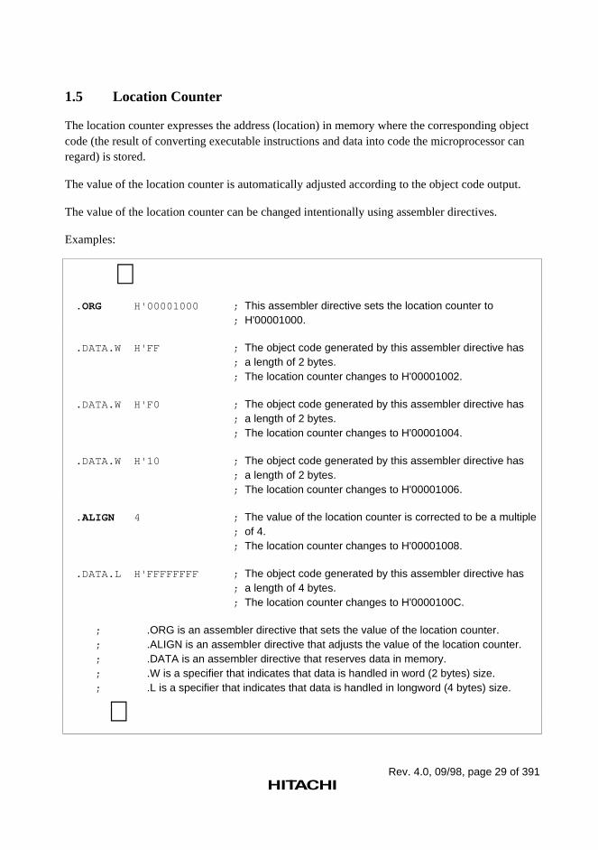
1.5 Location Counter
The location counter expresses the address (location) in memory where the corresponding objectcode (the result of converting executable instructions and data into code the microprocessor canregard) is stored.
The value of the location counter is automatically adjusted according to the object code output.
The value of the location counter can be changed intentionally using assembler directives.
Examples:
∼ .ORG H'00001000 ; This assembler directive sets the location counter to ; H'00001000. .DATA.W H'FF ; The object code generated by this assembler directive has ; a length of 2 bytes. ; The location counter changes to H'00001002. .DATA.W H'F0 ; The object code generated by this assembler directive has ; a length of 2 bytes. ; The location counter changes to H'00001004. .DATA.W H'10 ; The object code generated by this assembler directive has ; a length of 2 bytes. ; The location counter changes to H'00001006. .ALIGN 4 ; The value of the location counter is corrected to be a multiple ; of 4. ; The location counter changes to H'00001008. .DATA.L H'FFFFFFFF ; The object code generated by this assembler directive has ; a length of 4 bytes. ; The location counter changes to H'0000100C. ; .ORG is an assembler directive that sets the value of the location counter. ; .ALIGN is an assembler directive that adjusts the value of the location counter. ; .DATA is an assembler directive that reserves data in memory. ; .W is a specifier that indicates that data is handled in word (2 bytes) size. ; .L is a specifier that indicates that data is handled in longword (4 bytes) size. ∼
Rev. 4.0, 09/98, page 30 of 391
References:
Setting the value of the location counter → Programmer's Guide, 5.2.2, "Section and Location Counter Assembler Directives", .ORG
Correcting the value of the location counter → Programmer's Guide, 5.2.2, "Section and Location Counter Assembler Directives",
.ALIGN
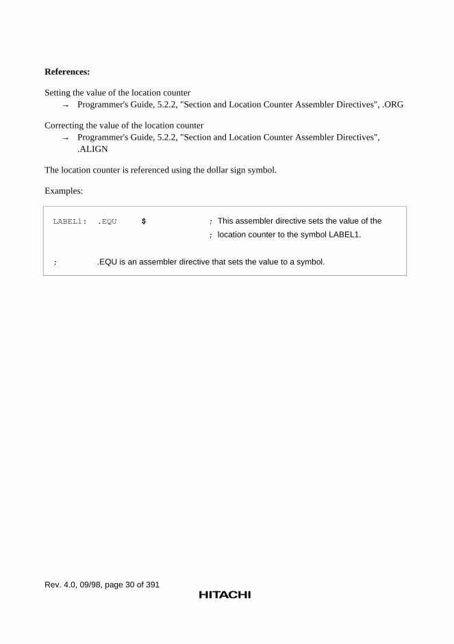
The location counter is referenced using the dollar sign symbol.
Examples:
LABEL1: .EQU $ ; This assembler directive sets the value of the
; location counter to the symbol LABEL1.
; .EQU is an assembler directive that sets the value to a symbol.
Rev. 4.0, 09/98, page 31 of 391
1.6 Expressions
Expressions are combinations of constants, symbols, and operators that derive a value, and areused as the operands of executable instructions and assembler directives.
1.6.1 Elements of Expression
An expression consists of terms, operators, and parentheses.
(1) Terms
The terms are the followings:
• A constant
• The location counter reference ($)
• A symbol (excluding aliases of the register name)
• The result of a calculation specified by a combination of the above terms and an operator.
An independent term is also a type of expression.
(2) Operators
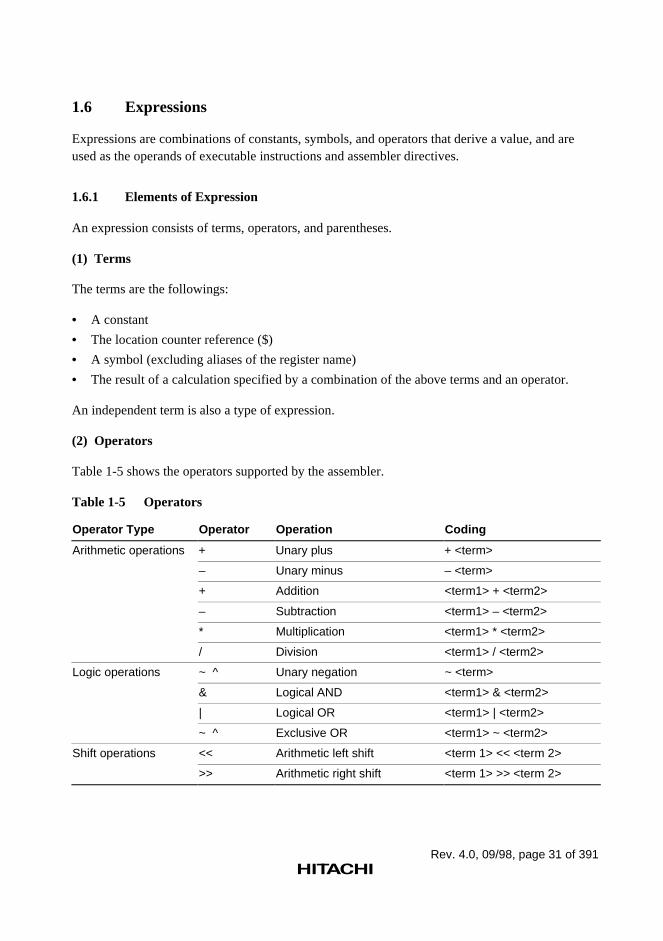
Table 1-5 shows the operators supported by the assembler.
Table 1-5 Operators
Operator Type Operator Operation Coding
Arithmetic operations + Unary plus + <term>
– Unary minus – <term>
+ Addition <term1> + <term2>
– Subtraction <term1> – <term2>
* Multiplication <term1> * <term2>
/ Division <term1> / <term2>
Logic operations ~ ^ Unary negation ~ <term>
& Logical AND <term1> & <term2>
| Logical OR <term1> | <term2>
~ ^ Exclusive OR <term1> ~ <term2>
Shift operations << Arithmetic left shift <term 1> << <term 2>
>> Arithmetic right shift <term 1> >> <term 2>
Rev. 4.0, 09/98, page 32 of 391
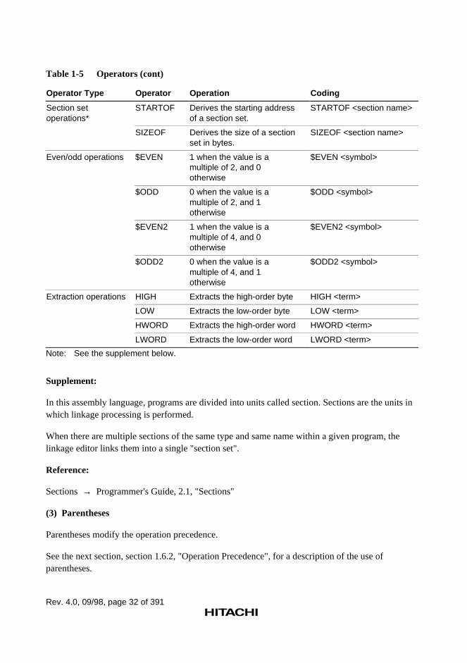
Table 1-5 Operators (cont)
Operator Type Operator Operation Coding
Section setoperations*
STARTOF Derives the starting addressof a section set.
STARTOF <section name>
SIZEOF Derives the size of a sectionset in bytes.
SIZEOF <section name>
Even/odd operations $EVEN 1 when the value is amultiple of 2, and 0otherwise
$EVEN <symbol>
$ODD 0 when the value is amultiple of 2, and 1otherwise
$ODD <symbol>
$EVEN2 1 when the value is amultiple of 4, and 0otherwise
$EVEN2 <symbol>
$ODD2 0 when the value is amultiple of 4, and 1otherwise
$ODD2 <symbol>
Extraction operations HIGH Extracts the high-order byte HIGH <term>
LOW Extracts the low-order byte LOW <term>
HWORD Extracts the high-order word HWORD <term>
LWORD Extracts the low-order word LWORD <term>
Note: See the supplement below.
Supplement:
In this assembly language, programs are divided into units called section. Sections are the units inwhich linkage processing is performed.
When there are multiple sections of the same type and same name within a given program, thelinkage editor links them into a single "section set".
Reference:
Sections → Programmer's Guide, 2.1, "Sections"
(3) Parentheses
Parentheses modify the operation precedence.
See the next section, section 1.6.2, "Operation Precedence", for a description of the use ofparentheses.
Rev. 4.0, 09/98, page 33 of 391
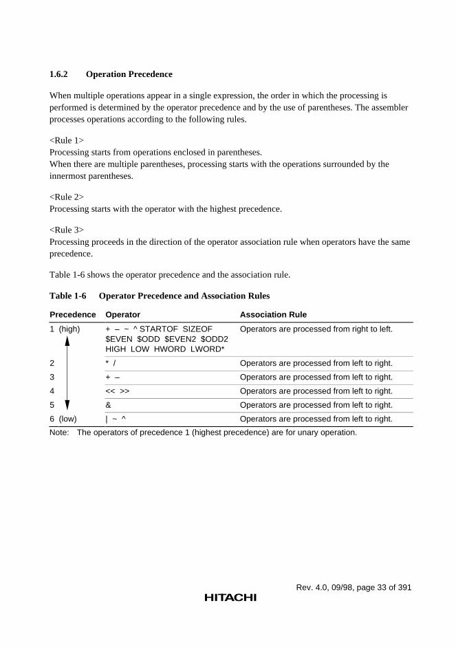
1.6.2 Operation Precedence
When multiple operations appear in a single expression, the order in which the processing isperformed is determined by the operator precedence and by the use of parentheses. The assemblerprocesses operations according to the following rules.
<Rule 1>Processing starts from operations enclosed in parentheses.When there are multiple parentheses, processing starts with the operations surrounded by theinnermost parentheses.
<Rule 2>Processing starts with the operator with the highest precedence.
<Rule 3>Processing proceeds in the direction of the operator association rule when operators have the sameprecedence.
Table 1-6 shows the operator precedence and the association rule.
Table 1-6 Operator Precedence and Association Rules
Precedence Operator Association Rule
1 (high) + – ~ ^ STARTOF SIZEOF$EVEN $ODD $EVEN2 $ODD2HIGH LOW HWORD LWORD*
Operators are processed from right to left.
2 * / Operators are processed from left to right.
3 + – Operators are processed from left to right.
4 << >> Operators are processed from left to right.
5 & Operators are processed from left to right.
6 (low) | ~ ^ Operators are processed from left to right.
Note: The operators of precedence 1 (highest precedence) are for unary operation.
Rev. 4.0, 09/98, page 34 of 391
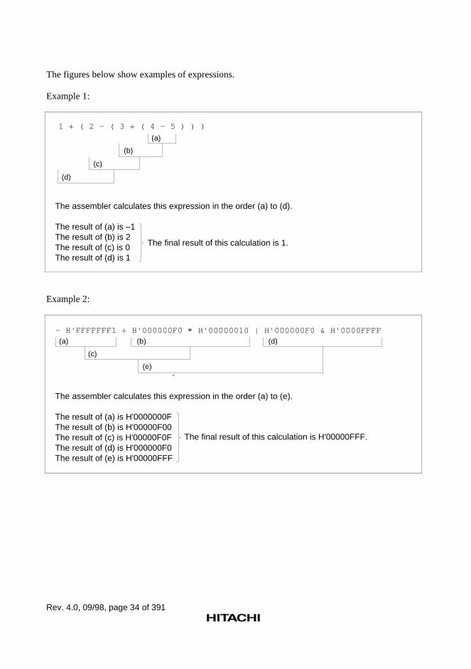
The figures below show examples of expressions.
Example 1:
1 + ( 2 - ( 3 + ( 4 - 5 ) ) )
(a)
(b)
(c)
(d)
The assembler calculates this expression in the order (a) to (d).
The result of (a) is –1The result of (b) is 2The result of (c) is 0The result of (d) is 1
The final result of this calculation is 1.
Example 2:
- H'FFFFFFF1 + H'000000F0 *(a) (b) (d)
(c)
(e)
H'00000010 | H'000000F0 & H'0000FFFF
The assembler calculates this expression in the order (a) to (e).
The result of (a) is H'0000000FThe result of (b) is H'00000F00The result of (c) is H'00000F0FThe result of (d) is H'000000F0The result of (e) is H'00000FFF
The final result of this calculation is H'00000FFF.
Rev. 4.0, 09/98, page 35 of 391
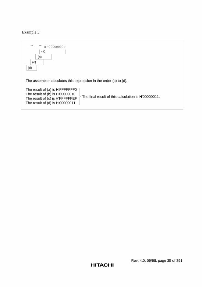
Example 3:
- - H'0000000F(a)
(b)
(c)
(d)
~ ~
The assembler calculates this expression in the order (a) to (d).
The result of (a) is H'FFFFFFF0The result of (b) is H'00000010The result of (c) is H'FFFFFFEFThe result of (d) is H'00000011
The final result of this calculation is H'00000011.
Rev. 4.0, 09/98, page 36 of 391
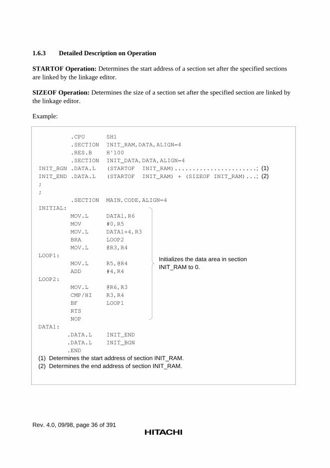
1.6.3 Detailed Description on Operation
STARTOF Operation: Determines the start address of a section set after the specified sectionsare linked by the linkage editor.
SIZEOF Operation: Determines the size of a section set after the specified section are linked bythe linkage editor.
Example:
.CPU SH1
.SECTION INIT_RAM,DATA,ALIGN=4
.RES.B H'100
.SECTION INIT_DATA,DATA,ALIGN=4
INIT_BGN .DATA.L (STARTOF INIT_RAM)....................... ; (1)INIT_END .DATA.L (STARTOF INIT_RAM) + (SIZEOF INIT_RAM)... ; (2);
;
.SECTION MAIN,CODE,ALIGN=4
INITIAL:
MOV.L DATA1,R6
MOV #0,R5
MOV.L DATA1+4,R3
BRA LOOP2
MOV.L @R3,R4
LOOP1:
MOV.L R5,@R4
ADD #4,R4
LOOP2:
MOV.L @R6,R3
CMP/HI R3,R4
BF LOOP1
RTS
NOP
DATA1:
.DATA.L INIT_END
.DATA.L INIT_BGN
.END
(1) Determines the start address of section INIT_RAM.(2) Determines the end address of section INIT_RAM.
Initializes the data area in sectionINIT_RAM to 0.
Rev. 4.0, 09/98, page 37 of 391
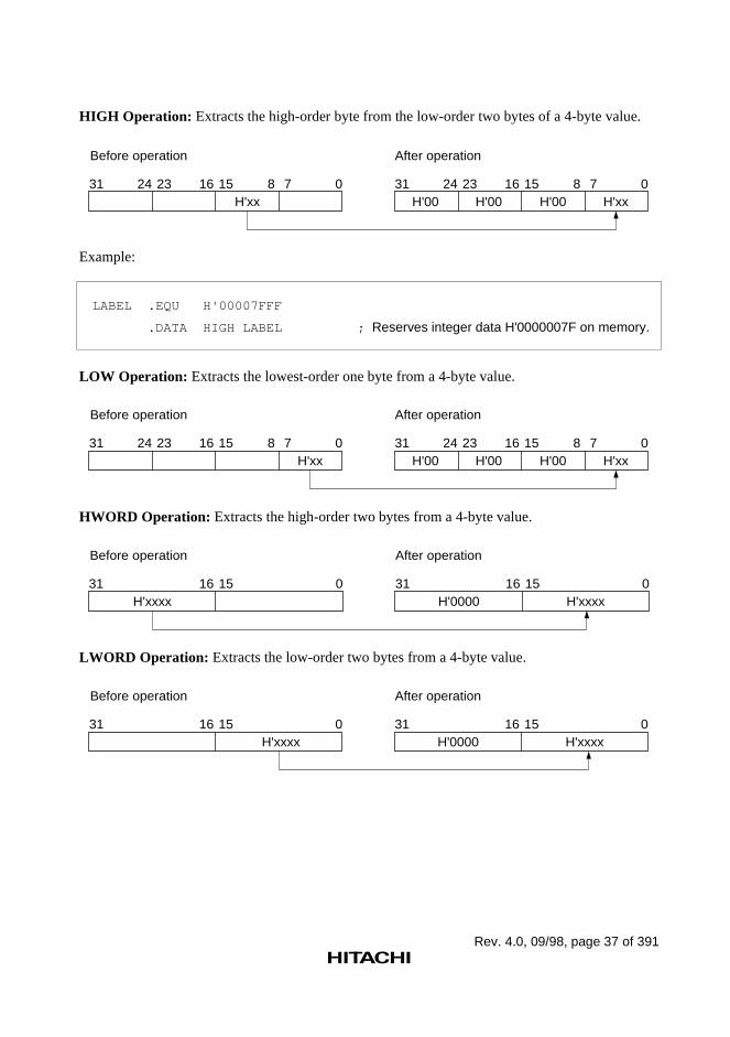
HIGH Operation: Extracts the high-order byte from the low-order two bytes of a 4-byte value.
H'00 H'00 H'00 H'xx31 24 23 16 15 8 7 0
H'xx31 24 23 16 15 8 7 0
After operationBefore operation
Example:
LABEL .EQU H'00007FFF
.DATA HIGH LABEL ; Reserves integer data H'0000007F on memory.
LOW Operation: Extracts the lowest-order one byte from a 4-byte value.
H'00 H'00 H'00 H'xx31 24 23 16 15 8 7 0
H'xx31 24 23 16 15 8 7 0
After operationBefore operation
HWORD Operation: Extracts the high-order two bytes from a 4-byte value.
H'0000 H'xxxx31 16 15 0
H'xxxx31 16 15 0
After operationBefore operation
LWORD Operation: Extracts the low-order two bytes from a 4-byte value.
H'0000 H'xxxx31 16 15 0
H'xxxx31 16 15 0
After operationBefore operation
Rev. 4.0, 09/98, page 38 of 391
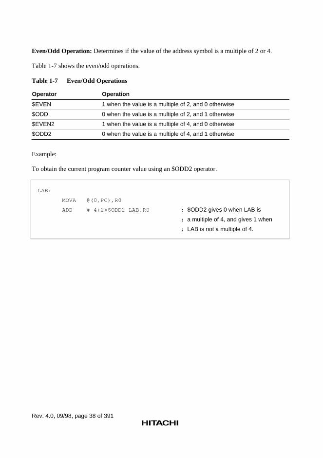
Even/Odd Operation: Determines if the value of the address symbol is a multiple of 2 or 4.
Table 1-7 shows the even/odd operations.
Table 1-7 Even/Odd Operations
Operator Operation
$EVEN 1 when the value is a multiple of 2, and 0 otherwise
$ODD 0 when the value is a multiple of 2, and 1 otherwise
$EVEN2 1 when the value is a multiple of 4, and 0 otherwise
$ODD2 0 when the value is a multiple of 4, and 1 otherwise
Example:
To obtain the current program counter value using an $ODD2 operator.
LAB:
MOVA @(0,PC),R0
ADD #-4+2 * $ODD2 LAB,R0 ; $ODD2 gives 0 when LAB is
; a multiple of 4, and gives 1 when
; LAB is not a multiple of 4.
Rev. 4.0, 09/98, page 39 of 391
1.6.4 Notes on Expressions
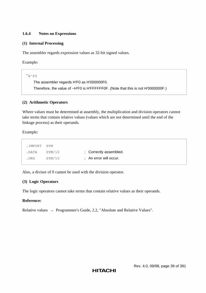
(1) Internal Processing
The assembler regards expression values as 32-bit signed values.
Example:
~H'F0
The assembler regards H'F0 as H'000000F0.
Therefore, the value of ~H'F0 is H'FFFFFF0F. (Note that this is not H'0000000F.)
(2) Arithmetic Operators
Where values must be determined at assembly, the multiplication and division operators cannottake terms that contain relative values (values which are not determined until the end of thelinkage process) as their operands.
Example:
.IMPORT SYM
.DATA SYM/10 ; Correctly assembled.
.ORG SYM/10 ; An error will occur.
Also, a divisor of 0 cannot be used with the division operator.
(3) Logic Operators
The logic operators cannot take terms that contain relative values as their operands.
Reference:
Relative values → Programmer's Guide, 2.2, "Absolute and Relative Values".
Rev. 4.0, 09/98, page 40 of 391
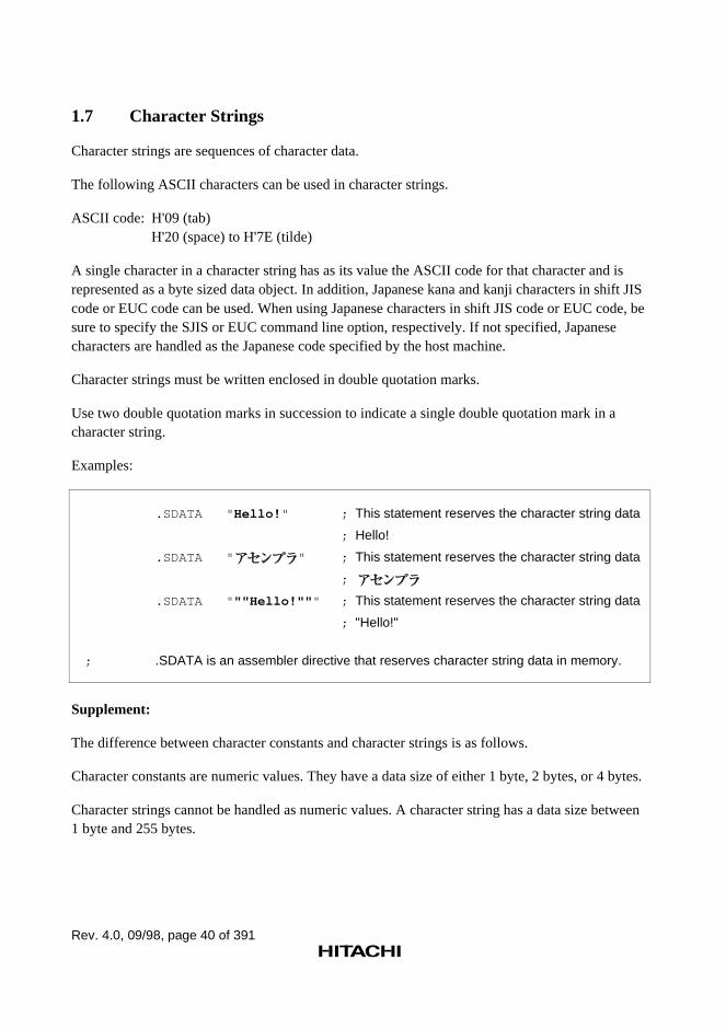
1.7 Character Strings
Character strings are sequences of character data.
The following ASCII characters can be used in character strings.
ASCII code: H'09 (tab)H'20 (space) to H'7E (tilde)
A single character in a character string has as its value the ASCII code for that character and isrepresented as a byte sized data object. In addition, Japanese kana and kanji characters in shift JIScode or EUC code can be used. When using Japanese characters in shift JIS code or EUC code, besure to specify the SJIS or EUC command line option, respectively. If not specified, Japanesecharacters are handled as the Japanese code specified by the host machine.
Character strings must be written enclosed in double quotation marks.
Use two double quotation marks in succession to indicate a single double quotation mark in acharacter string.
Examples:
.SDATA " Hello! " ; This statement reserves the character string data
; Hello!
.SDATA " " ; This statement reserves the character string data
;
.SDATA " ""Hello!"" " ; This statement reserves the character string data
; "Hello!"
; .SDATA is an assembler directive that reserves character string data in memory.
Supplement:
The difference between character constants and character strings is as follows.
Character constants are numeric values. They have a data size of either 1 byte, 2 bytes, or 4 bytes.
Character strings cannot be handled as numeric values. A character string has a data size between1 byte and 255 bytes.
Rev. 4.0, 09/98, page 41 of 391
References:
SJIS command line option→ User's Guide, 2.2.7, "Japanese Character Command Line Options," –SJIS
EUC command line option→ User's Guide, 2.2.7, "Japanese Character Command Line Options," –EUC
Rev. 4.0, 09/98, page 42 of 391
1.8 Local Label
1.8.1 Local Label Functions
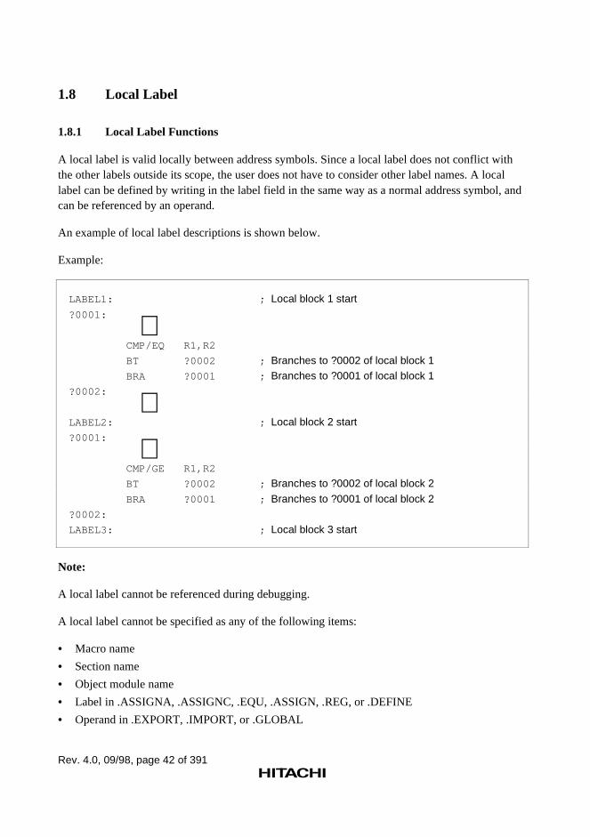
A local label is valid locally between address symbols. Since a local label does not conflict withthe other labels outside its scope, the user does not have to consider other label names. A locallabel can be defined by writing in the label field in the same way as a normal address symbol, andcan be referenced by an operand.
An example of local label descriptions is shown below.
Example:
LABEL1: ; Local block 1 start
?0001:
∼ CMP/EQ R1,R2
BT ?0002 ; Branches to ?0002 of local block 1 BRA ?0001 ; Branches to ?0001 of local block 1?0002:
∼LABEL2: ; Local block 2 start?0001:
∼ CMP/GE R1,R2
BT ?0002 ; Branches to ?0002 of local block 2
BRA ?0001 ; Branches to ?0001 of local block 2?0002:
LABEL3: ; Local block 3 start
Note:
A local label cannot be referenced during debugging.
A local label cannot be specified as any of the following items:
• Macro name
• Section name
• Object module name
• Label in .ASSIGNA, .ASSIGNC, .EQU, .ASSIGN, .REG, or .DEFINE
• Operand in .EXPORT, .IMPORT, or .GLOBAL
Rev. 4.0, 09/98, page 43 of 391
1.8.2 Description Method of Local Label
First Character:
A local label is a character string starting with a question mark (?).
Usable Characters:
The following ASCII characters can be used in a local label, except for the first character:
• Alphabetical uppercase and lowercase letters (A to Z and a to z)
• Numbers (0 to 9)
• Underscore (_)
• Dollar sign ($)
The assembler distinguishes uppercase letters from lowercase ones in local labels.
Maximum Length:
The length of local label characters is 2 to 16 characters. If 17 or more characters are specified, theassembler will not recognize them as a local label.
1.8.3 Scope of Local Labels
The scope of a local label is called a local block. Local blocks are separated by address symbols,or by the .SECTION directives.
The local label defined within a local block can be referenced in that local block.
A local label belonging to a local block is interpreted as being unique even if its spelling is thesame as local labels in other local blocks; it does not cause an error.
Note:
The address symbols defined by the .EQU or .ASSIGN directive are not interpreted as delimitersfor the local block.
Rev. 4.0, 09/98, page 45 of 391
Section 2 Basic Programming Knowledge
2.1 Sections
If source programs are compared to natural language writing, a section will correspond to a"chapter." The section is the processing unit used when the linkage editor links object modules.
2.1.1 Section Types by Usage
Sections are classified by usage into the following types.
• Code section
• Data section
• Common section
• Stack section
• Dummy section
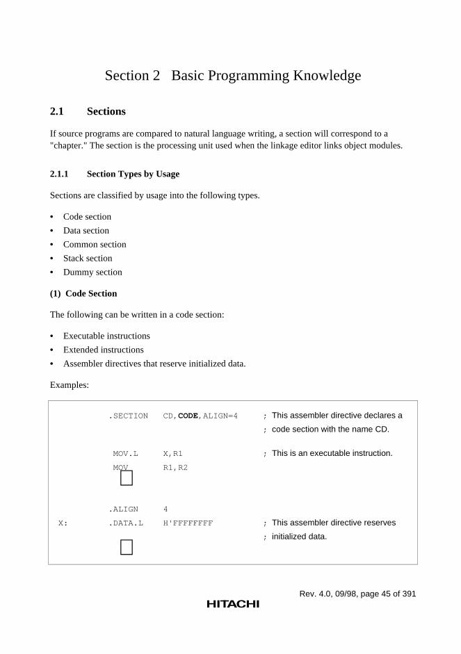
(1) Code Section
The following can be written in a code section:
• Executable instructions
• Extended instructions
• Assembler directives that reserve initialized data.
Examples:
.SECTION CD, CODE,ALIGN=4 ; This assembler directive declares a
; code section with the name CD.
MOV.L X,R1 ; This is an executable instruction.
MOV R1,R2
∼ .ALIGN 4
X: .DATA.L H'FFFFFFFF ; This assembler directive reserves
; initialized data.
∼
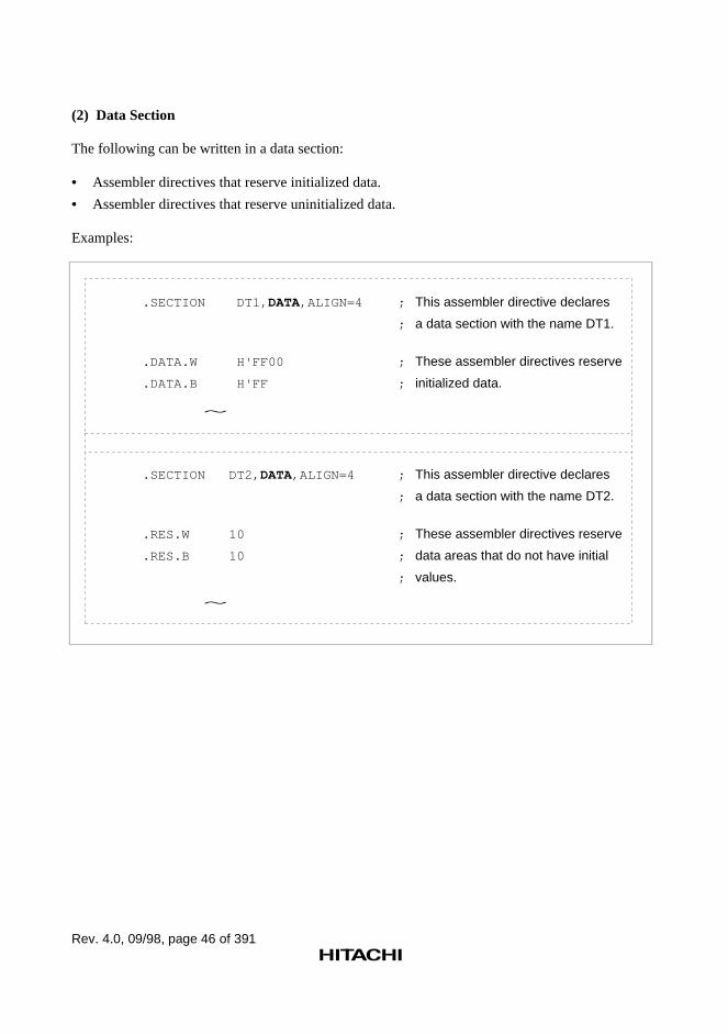
Rev. 4.0, 09/98, page 46 of 391
(2) Data Section
The following can be written in a data section:
• Assembler directives that reserve initialized data.
• Assembler directives that reserve uninitialized data.
Examples:
.SECTION DT1, DATA,ALIGN=4 ; This assembler directive declares
; a data section with the name DT1.
.DATA.W H'FF00 ; These assembler directives reserve
.DATA.B H'FF ; initialized data.
.SECTION DT2, DATA,ALIGN=4 ; This assembler directive declares
; a data section with the name DT2.
.RES.W 10 ; These assembler directives reserve
.RES.B 10 ; data areas that do not have initial
; values.
~
~
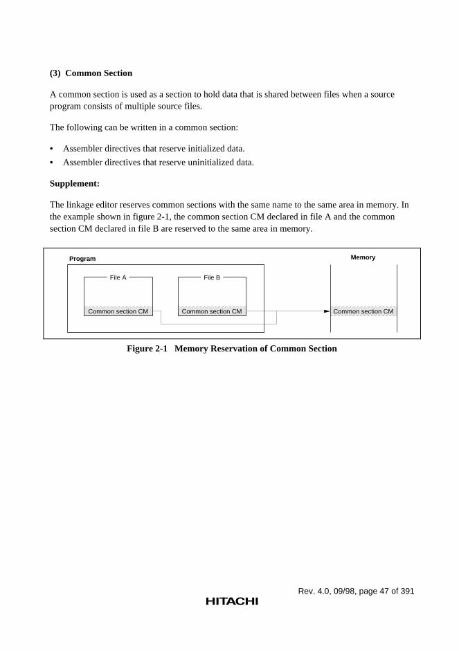
Rev. 4.0, 09/98, page 47 of 391
(3) Common Section
A common section is used as a section to hold data that is shared between files when a sourceprogram consists of multiple source files.
The following can be written in a common section:
• Assembler directives that reserve initialized data.
• Assembler directives that reserve uninitialized data.
Supplement:
The linkage editor reserves common sections with the same name to the same area in memory. Inthe example shown in figure 2-1, the common section CM declared in file A and the commonsection CM declared in file B are reserved to the same area in memory.
File A File B
Common section CM
Memory
Common section CM
Program
Common section CM
Figure 2-1 Memory Reservation of Common Section
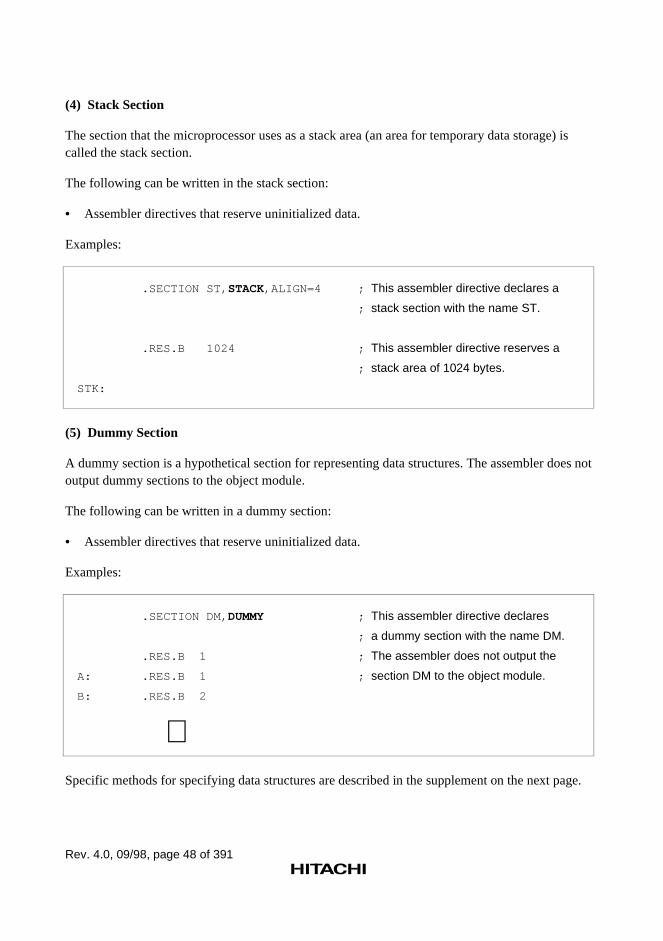
Rev. 4.0, 09/98, page 48 of 391
(4) Stack Section
The section that the microprocessor uses as a stack area (an area for temporary data storage) iscalled the stack section.
The following can be written in the stack section:
• Assembler directives that reserve uninitialized data.
Examples:
.SECTION ST, STACK,ALIGN=4 ; This assembler directive declares a
; stack section with the name ST.
.RES.B 1024 ; This assembler directive reserves a
; stack area of 1024 bytes.
STK:
(5) Dummy Section
A dummy section is a hypothetical section for representing data structures. The assembler does notoutput dummy sections to the object module.
The following can be written in a dummy section:
• Assembler directives that reserve uninitialized data.
Examples:
.SECTION DM, DUMMY ; This assembler directive declares
; a dummy section with the name DM.
.RES.B 1 ; The assembler does not output the
A: .RES.B 1 ; section DM to the object module.
B: .RES.B 2
∼Specific methods for specifying data structures are described in the supplement on the next page.
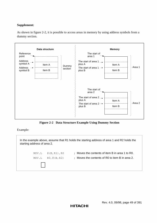
Rev. 4.0, 09/98, page 49 of 391
Supplement:
As shown in figure 2-2, it is possible to access areas in memory by using address symbols from adummy section.
Data structure
Reference point
Address symbol A
Address symbol B
Item A
Item B
Dummy section
Memory
The start of area 1
The start of area 1 plus AThe start of area 1 plus B
Item A
Item BArea 1
The start of area 2
The start of area 2 plus AThe start of area 2 plus B
Item A
Item BArea 2
Figure 2-2 Data Structure Example Using Dummy Section
Example:
In the example above, assume that R1 holds the starting address of area 1 and R2 holds thestarting address of area 2.
MOV.L @(B,R1),R0 ; Moves the contents of item B in area 1 to R0.
MOV.L R0,@(B,R2) ; Moves the contents of R0 to item B in area 2.
∼
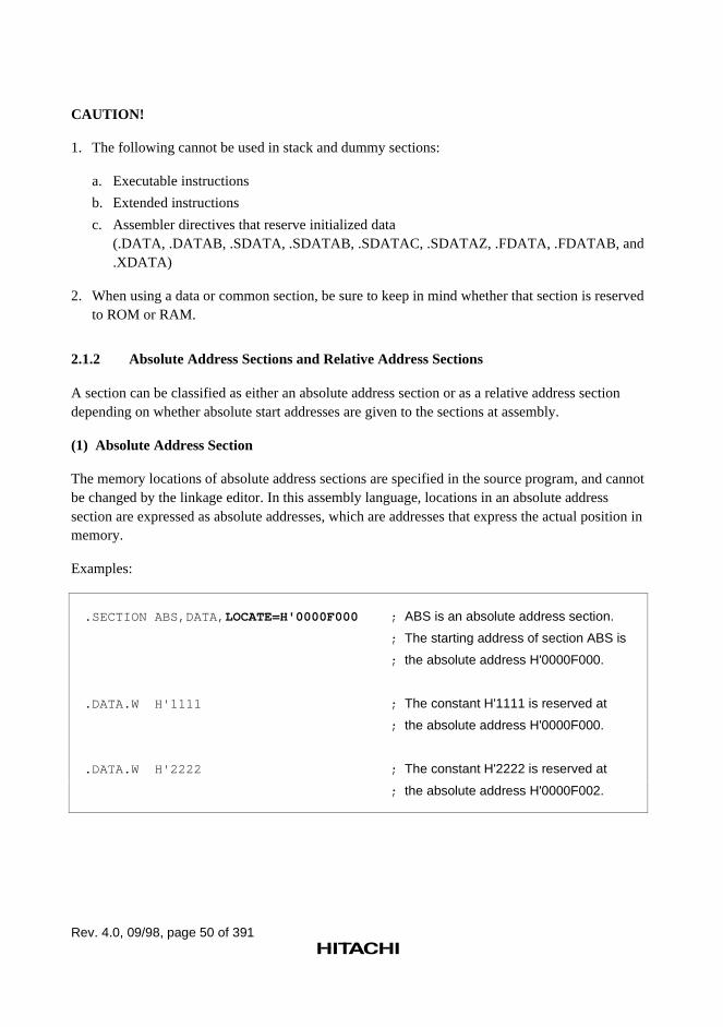
Rev. 4.0, 09/98, page 50 of 391
CAUTION!
1. The following cannot be used in stack and dummy sections:
a. Executable instructions
b. Extended instructions
c. Assembler directives that reserve initialized data(.DATA, .DATAB, .SDATA, .SDATAB, .SDATAC, .SDATAZ, .FDATA, .FDATAB, and.XDATA)
2. When using a data or common section, be sure to keep in mind whether that section is reservedto ROM or RAM.
2.1.2 Absolute Address Sections and Relative Address Sections
A section can be classified as either an absolute address section or as a relative address sectiondepending on whether absolute start addresses are given to the sections at assembly.
(1) Absolute Address Section
The memory locations of absolute address sections are specified in the source program, and cannotbe changed by the linkage editor. In this assembly language, locations in an absolute addresssection are expressed as absolute addresses, which are addresses that express the actual position inmemory.
Examples:
.SECTION ABS,DATA, LOCATE=H'0000F000 ; ABS is an absolute address section.
; The starting address of section ABS is
; the absolute address H'0000F000.
.DATA.W H'1111 ; The constant H'1111 is reserved at
; the absolute address H'0000F000.
.DATA.W H'2222 ; The constant H'2222 is reserved at
; the absolute address H'0000F002.
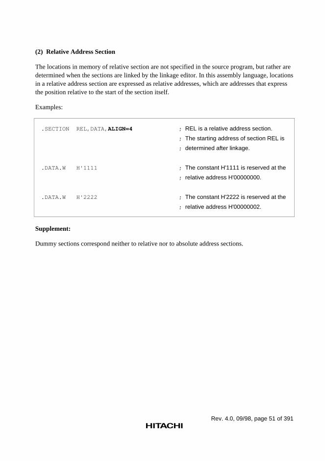
Rev. 4.0, 09/98, page 51 of 391
(2) Relative Address Section
The locations in memory of relative section are not specified in the source program, but rather aredetermined when the sections are linked by the linkage editor. In this assembly language, locationsin a relative address section are expressed as relative addresses, which are addresses that expressthe position relative to the start of the section itself.
Examples:
.SECTION REL,DATA, ALIGN=4 ; REL is a relative address section.
; The starting address of section REL is
; determined after linkage.
.DATA.W H'1111 ; The constant H'1111 is reserved at the
; relative address H'00000000.
.DATA.W H'2222 ; The constant H'2222 is reserved at the
; relative address H'00000002.
Supplement:
Dummy sections correspond neither to relative nor to absolute address sections.
Rev. 4.0, 09/98, page 52 of 391
2.2 Absolute and Relative Values
Absolute values are determined when assembly completes. Relative values are not determineduntil the linkage editor completes.
2.2.1 Absolute Values
The following are the absolute values handled by the assembler.
(1) Constants
• Integer constants
• Character constants
• Symbols that have a value that is one of the above (hereafter referred to as constant symbols).
(2) Absolute Address Values
• The location counter referenced in an absolute address section
• The location counter referenced in a dummy section
• Symbols that have a value that is one of the above (hereafter referred to as absolute addresssymbols).
(3) Other Absolute Values
Expressions whose value is determined when assembly completes.
2.2.2 Relative Values
The following are the relative values handled by the assembler.
(1) Relative Address Values
• The location counter referenced in a relative address section
• Symbols that have the above as a value (hereafter referred to as relative address symbols).
(2) External Reference Values
Symbols that reference another file (hereafter referred to as import symbols).
(3) Other Relative Values
Expressions whose value is not determined until the linkage editor completes.
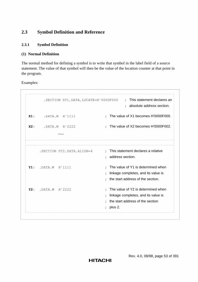
Rev. 4.0, 09/98, page 53 of 391
2.3 Symbol Definition and Reference
2.3.1 Symbol Definition
(1) Normal Definition
The normal method for defining a symbol is to write that symbol in the label field of a sourcestatement. The value of that symbol will then be the value of the location counter at that point inthe program.
Examples:
.SECTION DT1,DATA,LOCATE=H'0000F000 ; This statement declares an
; absolute address section.
X1: .DATA.W H'1111 ; The value of X1 becomes H'0000F000.
X2: .DATA.W H'2222 ; The value of X2 becomes H'0000F002.
.SECTION DT2,DATA,ALIGN=4 ; This statement declares a relative
; address section.
Y1: .DATA.W H'1111 ; The value of Y1 is determined when
; linkage completes, and its value is
; the start address of the section.
Y2: .DATA.W H'2222 ; The value of Y2 is determined when
; linkage completes, and its value is
; the start address of the section
; plus 2.
~
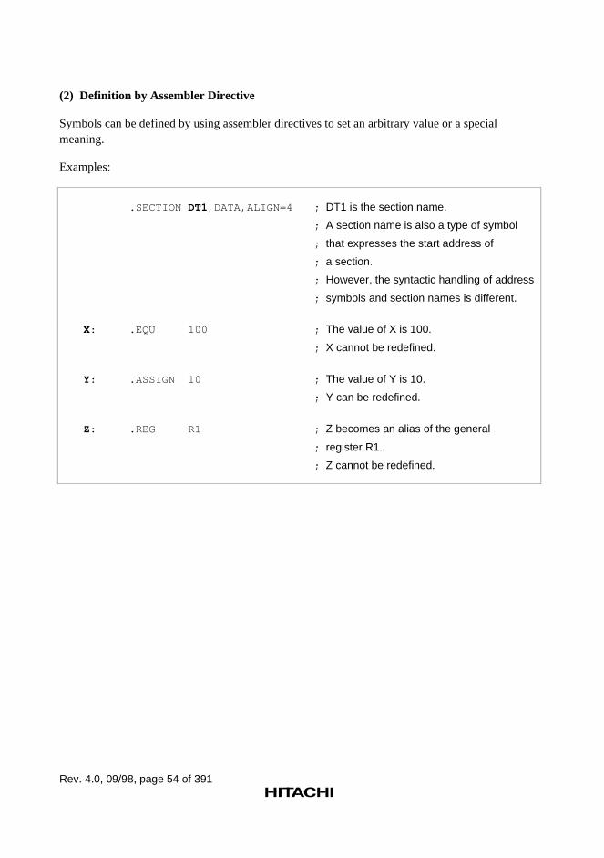
Rev. 4.0, 09/98, page 54 of 391
(2) Definition by Assembler Directive
Symbols can be defined by using assembler directives to set an arbitrary value or a specialmeaning.
Examples:
.SECTION DT1,DATA,ALIGN=4 ; DT1 is the section name.
; A section name is also a type of symbol
; that expresses the start address of
; a section.
; However, the syntactic handling of address
; symbols and section names is different.
X: .EQU 100 ; The value of X is 100.
; X cannot be redefined.
Y: .ASSIGN 10 ; The value of Y is 10.
; Y can be redefined.
Z: .REG R1 ; Z becomes an alias of the general
; register R1.
; Z cannot be redefined.
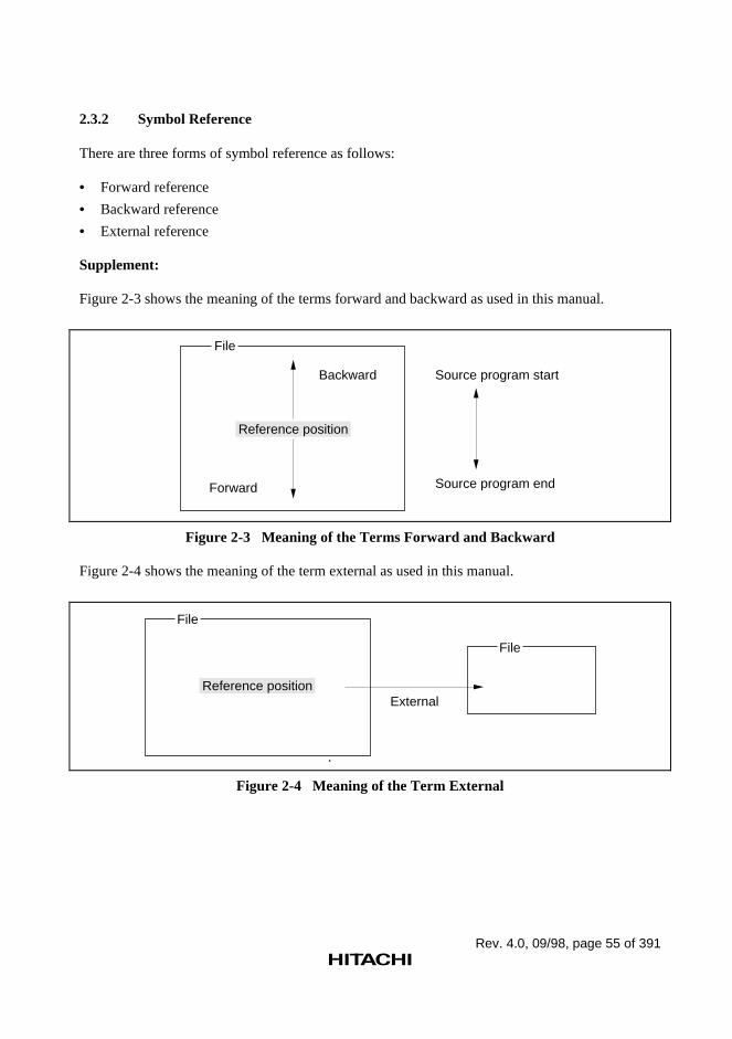
Rev. 4.0, 09/98, page 55 of 391
2.3.2 Symbol Reference
There are three forms of symbol reference as follows:
• Forward reference
• Backward reference
• External reference
Supplement:
Figure 2-3 shows the meaning of the terms forward and backward as used in this manual.
File
Backward
Forward
Source program start
Source program end
Reference position
Figure 2-3 Meaning of the Terms Forward and Backward
Figure 2-4 shows the meaning of the term external as used in this manual.
File
Reference position
File
External
Figure 2-4 Meaning of the Term External
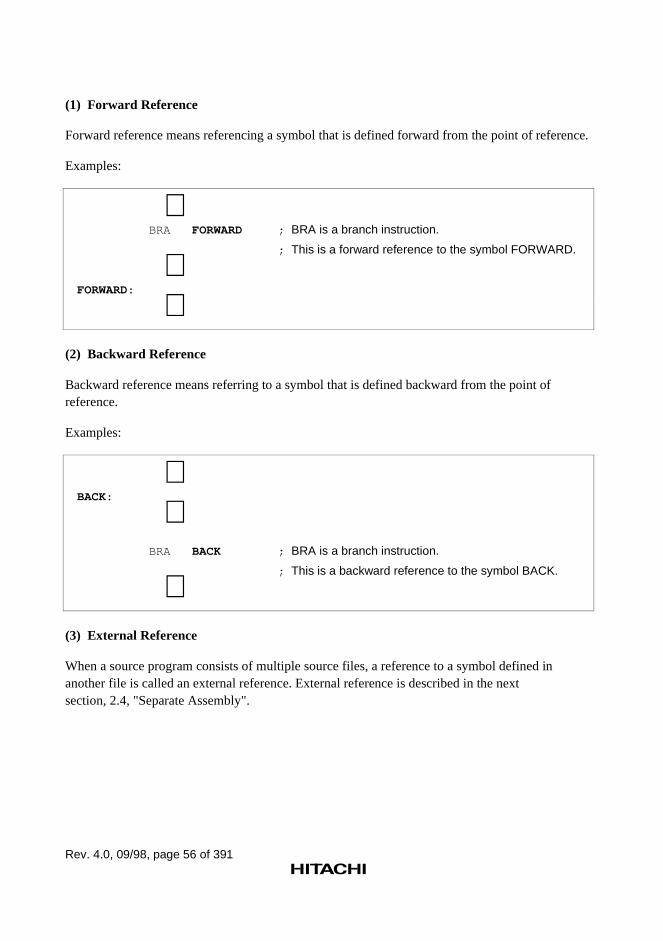
Rev. 4.0, 09/98, page 56 of 391
(1) Forward Reference
Forward reference means referencing a symbol that is defined forward from the point of reference.
Examples:
∼ BRA FORWARD ; BRA is a branch instruction.
; This is a forward reference to the symbol FORWARD.
∼FORWARD:
∼(2) Backward Reference
Backward reference means referring to a symbol that is defined backward from the point ofreference.
Examples:
∼BACK:
∼ BRA BACK ; BRA is a branch instruction.
; This is a backward reference to the symbol BACK.
∼(3) External Reference
When a source program consists of multiple source files, a reference to a symbol defined inanother file is called an external reference. External reference is described in the nextsection, 2.4, "Separate Assembly".
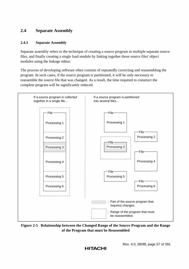
Rev. 4.0, 09/98, page 57 of 391
2.4 Separate Assembly
2.4.1 Separate Assembly
Separate assembly refers to the technique of creating a source program in multiple separate sourcefiles, and finally creating a single load module by linking together those source files' objectmodules using the linkage editor.
The process of developing software often consists of repeatedly correcting and reassembling theprogram. In such cases, if the source program is partitioned, it will be only necessary toreassemble the source file that was changed. As a result, the time required to construct thecomplete program will be significantly reduced.
If a source program is collected together in a single file...
File
Processing 1
Processing 2
Processing 4
Processing 5
Processing 6
If a source program is partitioned into several files...
File
Processing 1
Processing 5
File
: Part of the source program that requires changes.
: Range of the program that must be reassembled.
Processing 2
File
Processing 6
File
File
Processing 4
Processing 3 Processing 3File
Figure 2-5 Relationship between the Changed Range of the Source Program and the Rangeof the Program that must be Reassembled
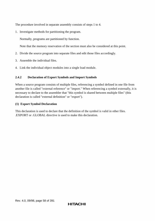
Rev. 4.0, 09/98, page 58 of 391
The procedure involved in separate assembly consists of steps 1 to 4.
1. Investigate methods for partitioning the program.
Normally, programs are partitioned by function.
Note that the memory reservation of the section must also be considered at this point.
2. Divide the source program into separate files and edit those files accordingly.
3. Assemble the individual files.
4. Link the individual object modules into a single load module.
2.4.2 Declaration of Export Symbols and Import Symbols
When a source program consists of multiple files, referencing a symbol defined in one file fromanother file is called "external reference" or "import." When referencing a symbol externally, it isnecessary to declare to the assembler that "this symbol is shared between multiple files" (thisdeclaration is called "external definition" or "export").
(1) Export Symbol Declaration
This declaration is used to declare that the definition of the symbol is valid in other files..EXPORT or .GLOBAL directive is used to make this declaration.
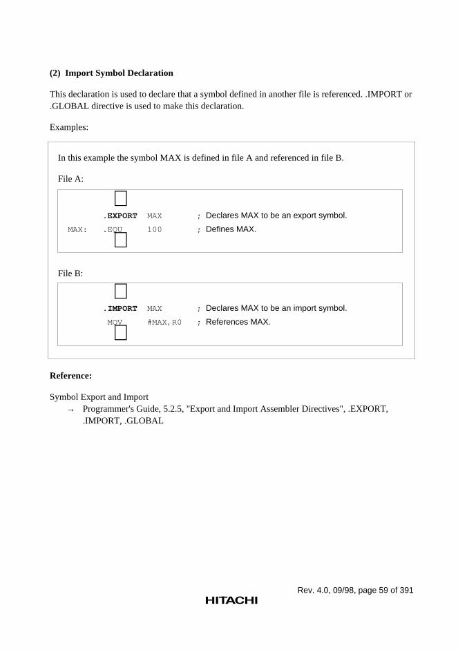
Rev. 4.0, 09/98, page 59 of 391
(2) Import Symbol Declaration
This declaration is used to declare that a symbol defined in another file is referenced. .IMPORT or.GLOBAL directive is used to make this declaration.
Examples:
In this example the symbol MAX is defined in file A and referenced in file B.
File A:
∼ .EXPORT MAX ; Declares MAX to be an export symbol.
MAX: .EQU 100 ; Defines MAX.
∼File B:
∼ .IMPORT MAX ; Declares MAX to be an import symbol.
MOV #MAX,R0 ; References MAX.
∼
Reference:
Symbol Export and Import→ Programmer's Guide, 5.2.5, "Export and Import Assembler Directives", .EXPORT,
.IMPORT, .GLOBAL
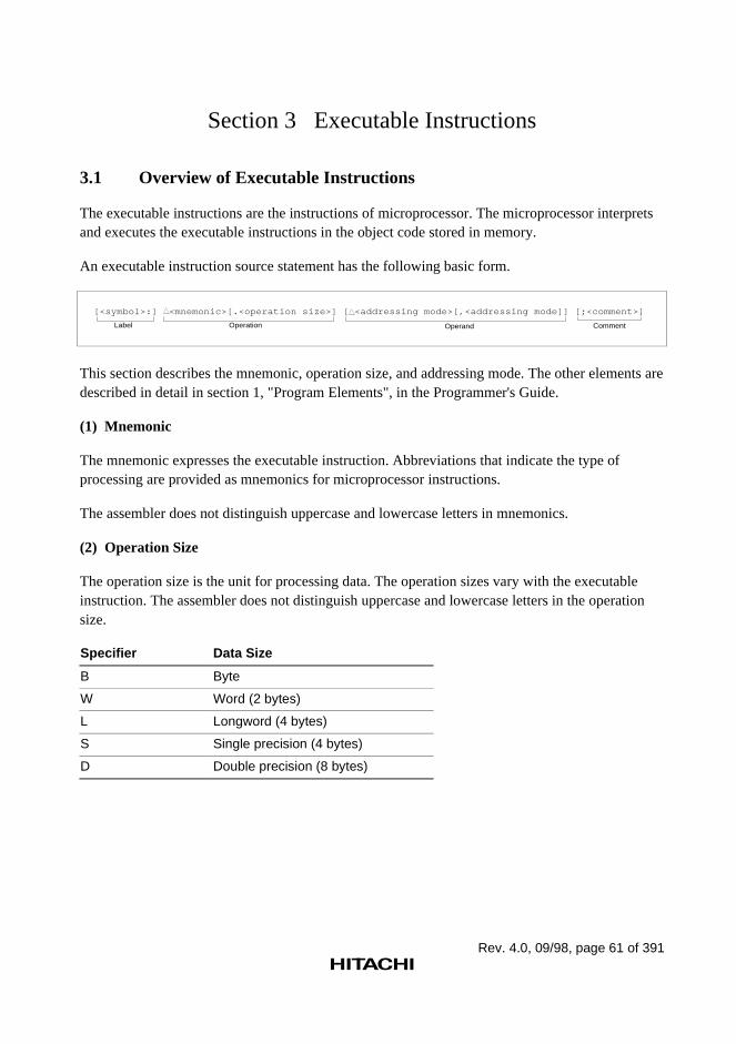
Rev. 4.0, 09/98, page 61 of 391
Section 3 Executable Instructions
3.1 Overview of Executable Instructions
The executable instructions are the instructions of microprocessor. The microprocessor interpretsand executes the executable instructions in the object code stored in memory.
An executable instruction source statement has the following basic form.
[<symbol>:] <mnemonic>[.<operation size>] [ <addressing mode>[,<addressing mode]] [;<comment>]
Label Operation Operand Comment
This section describes the mnemonic, operation size, and addressing mode. The other elements aredescribed in detail in section 1, "Program Elements", in the Programmer's Guide.
(1) Mnemonic
The mnemonic expresses the executable instruction. Abbreviations that indicate the type ofprocessing are provided as mnemonics for microprocessor instructions.
The assembler does not distinguish uppercase and lowercase letters in mnemonics.
(2) Operation Size
The operation size is the unit for processing data. The operation sizes vary with the executableinstruction. The assembler does not distinguish uppercase and lowercase letters in the operationsize.
Specifier Data Size
B Byte
W Word (2 bytes)
L Longword (4 bytes)
S Single precision (4 bytes)
D Double precision (8 bytes)
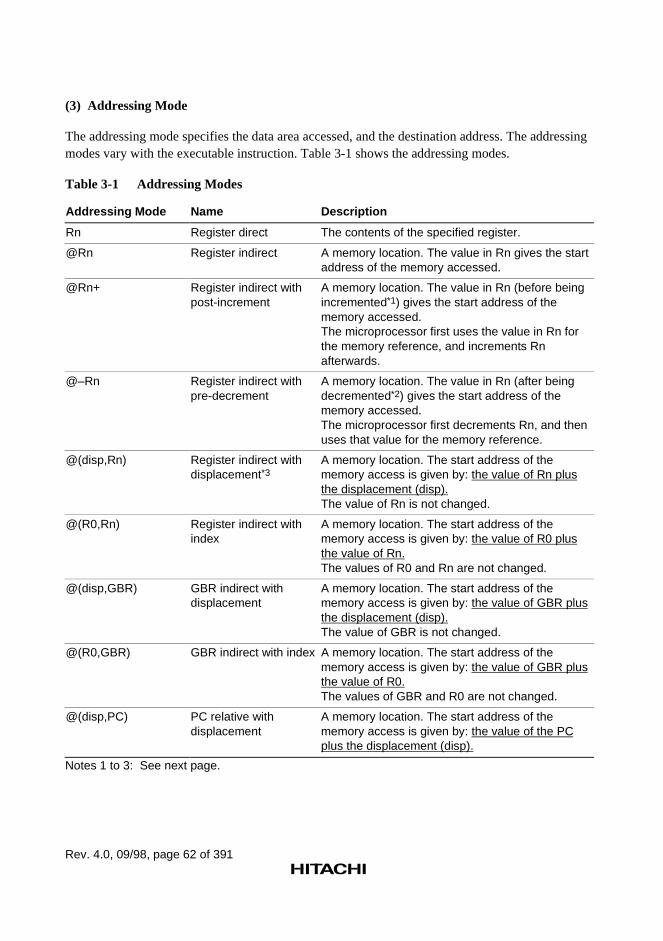
Rev. 4.0, 09/98, page 62 of 391
(3) Addressing Mode
The addressing mode specifies the data area accessed, and the destination address. The addressingmodes vary with the executable instruction. Table 3-1 shows the addressing modes.
Table 3-1 Addressing Modes
Addressing Mode Name Description
Rn Register direct The contents of the specified register.
@Rn Register indirect A memory location. The value in Rn gives the startaddress of the memory accessed.
@Rn+ Register indirect withpost-increment
A memory location. The value in Rn (before beingincremented*1) gives the start address of thememory accessed.The microprocessor first uses the value in Rn forthe memory reference, and increments Rnafterwards.
@–Rn Register indirect withpre-decrement
A memory location. The value in Rn (after beingdecremented*2) gives the start address of thememory accessed.The microprocessor first decrements Rn, and thenuses that value for the memory reference.
@(disp,Rn) Register indirect withdisplacement*3
A memory location. The start address of thememory access is given by: the value of Rn plusthe displacement (disp).The value of Rn is not changed.
@(R0,Rn) Register indirect withindex
A memory location. The start address of thememory access is given by: the value of R0 plusthe value of Rn.The values of R0 and Rn are not changed.
@(disp,GBR) GBR indirect withdisplacement
A memory location. The start address of thememory access is given by: the value of GBR plusthe displacement (disp).The value of GBR is not changed.
@(R0,GBR) GBR indirect with index A memory location. The start address of thememory access is given by: the value of GBR plusthe value of R0.The values of GBR and R0 are not changed.
@(disp,PC) PC relative withdisplacement
A memory location. The start address of thememory access is given by: the value of the PCplus the displacement (disp).
Notes 1 to 3: See next page.
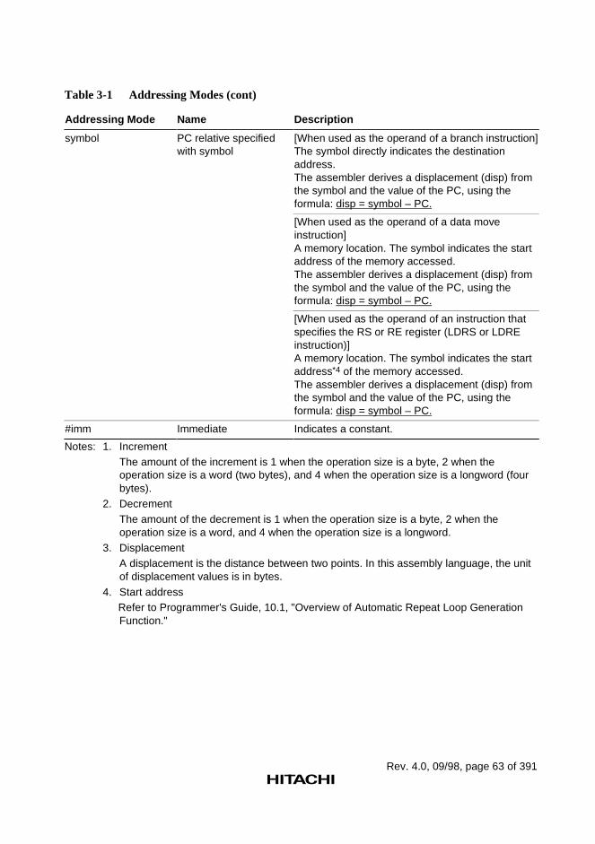
Rev. 4.0, 09/98, page 63 of 391
Table 3-1 Addressing Modes (cont)
Addressing Mode Name Description
symbol PC relative specifiedwith symbol
[When used as the operand of a branch instruction]The symbol directly indicates the destinationaddress.The assembler derives a displacement (disp) fromthe symbol and the value of the PC, using theformula: disp = symbol – PC.
[When used as the operand of a data moveinstruction]A memory location. The symbol indicates the startaddress of the memory accessed.The assembler derives a displacement (disp) fromthe symbol and the value of the PC, using theformula: disp = symbol – PC.
[When used as the operand of an instruction thatspecifies the RS or RE register (LDRS or LDREinstruction)]A memory location. The symbol indicates the startaddress*4 of the memory accessed.The assembler derives a displacement (disp) fromthe symbol and the value of the PC, using theformula: disp = symbol – PC.
#imm Immediate Indicates a constant.
Notes: 1. IncrementThe amount of the increment is 1 when the operation size is a byte, 2 when theoperation size is a word (two bytes), and 4 when the operation size is a longword (fourbytes).
2. DecrementThe amount of the decrement is 1 when the operation size is a byte, 2 when theoperation size is a word, and 4 when the operation size is a longword.
3. DisplacementA displacement is the distance between two points. In this assembly language, the unitof displacement values is in bytes.
4. Start addressRefer to Programmer's Guide, 10.1, "Overview of Automatic Repeat Loop GenerationFunction."
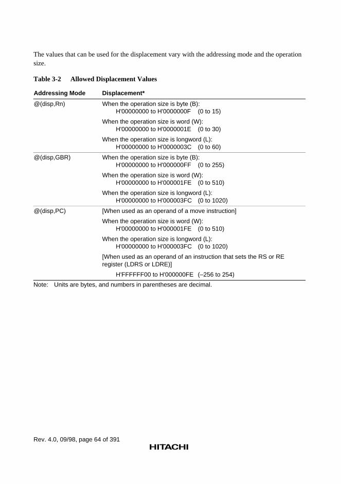
Rev. 4.0, 09/98, page 64 of 391
The values that can be used for the displacement vary with the addressing mode and the operationsize.
Table 3-2 Allowed Displacement Values
Addressing Mode Displacement*
@(disp,Rn) When the operation size is byte (B):H'00000000 to H'0000000F (0 to 15)
When the operation size is word (W):H'00000000 to H'0000001E (0 to 30)
When the operation size is longword (L):H'00000000 to H'0000003C (0 to 60)
@(disp,GBR) When the operation size is byte (B):H'00000000 to H'000000FF (0 to 255)
When the operation size is word (W):H'00000000 to H'000001FE (0 to 510)
When the operation size is longword (L):H'00000000 to H'000003FC (0 to 1020)
@(disp,PC) [When used as an operand of a move instruction]
When the operation size is word (W):H'00000000 to H'000001FE (0 to 510)
When the operation size is longword (L):H'00000000 to H'000003FC (0 to 1020)
[When used as an operand of an instruction that sets the RS or REregister (LDRS or LDRE)]
H'FFFFFF00 to H'000000FE (–256 to 254)
Note: Units are bytes, and numbers in parentheses are decimal.
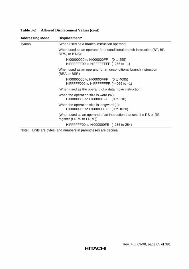
Rev. 4.0, 09/98, page 65 of 391
Table 3-2 Allowed Displacement Values (cont)
Addressing Mode Displacement*
symbol [When used as a branch instruction operand]
When used as an operand for a conditional branch instruction (BT, BF,BF/S, or BT/S):
H'00000000 to H'000000FF (0 to 255)H'FFFFFF00 to H'FFFFFFFF (–256 to –1)
When used as an operand for an unconditional branch instruction(BRA or BSR)
H'00000000 to H'00000FFF (0 to 4095)H'FFFFF000 to H'FFFFFFFF (–4096 to –1)
[When used as the operand of a data move instruction]
When the operation size is word (W):H'00000000 to H'000001FE (0 to 510)
When the operation size is longword (L):H'00000000 to H'000003FC (0 to 1020)
[When used as an operand of an instruction that sets the RS or REregister (LDRS or LDRE)]
H'FFFFFF00 to H'000000FE (–256 to 254)
Note: Units are bytes, and numbers in parentheses are decimal.
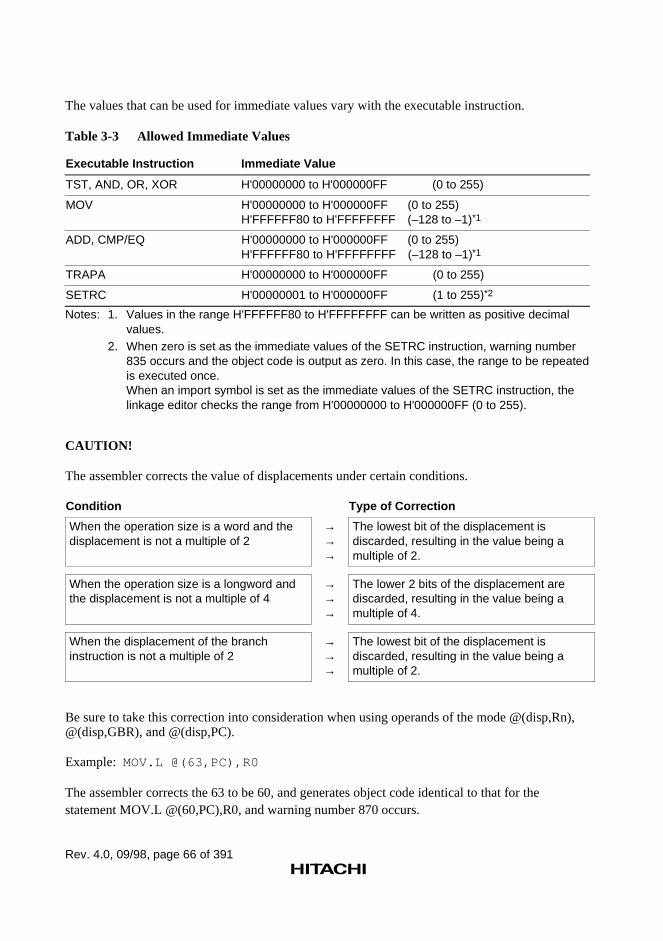
Rev. 4.0, 09/98, page 66 of 391
The values that can be used for immediate values vary with the executable instruction.
Table 3-3 Allowed Immediate Values
Executable Instruction Immediate Value
TST, AND, OR, XOR H'00000000 to H'000000FF (0 to 255)
MOV H'00000000 to H'000000FF (0 to 255)H'FFFFFF80 to H'FFFFFFFF (–128 to –1)*1
ADD, CMP/EQ H'00000000 to H'000000FF (0 to 255)H'FFFFFF80 to H'FFFFFFFF (–128 to –1)*1
TRAPA H'00000000 to H'000000FF (0 to 255)
SETRC H'00000001 to H'000000FF (1 to 255)*2
Notes: 1. Values in the range H'FFFFFF80 to H'FFFFFFFF can be written as positive decimalvalues.
2. When zero is set as the immediate values of the SETRC instruction, warning number835 occurs and the object code is output as zero. In this case, the range to be repeatedis executed once.When an import symbol is set as the immediate values of the SETRC instruction, thelinkage editor checks the range from H'00000000 to H'000000FF (0 to 255).
CAUTION!
The assembler corrects the value of displacements under certain conditions.
Condition Type of Correction
When the operation size is a word and thedisplacement is not a multiple of 2
→→→
The lowest bit of the displacement isdiscarded, resulting in the value being amultiple of 2.
When the operation size is a longword andthe displacement is not a multiple of 4
→→→
The lower 2 bits of the displacement arediscarded, resulting in the value being amultiple of 4.
When the displacement of the branchinstruction is not a multiple of 2
→→→
The lowest bit of the displacement isdiscarded, resulting in the value being amultiple of 2.
Be sure to take this correction into consideration when using operands of the mode @(disp,Rn),@(disp,GBR), and @(disp,PC).
Example: MOV.L @(63,PC),R0
The assembler corrects the 63 to be 60, and generates object code identical to that for thestatement MOV.L @(60,PC),R0, and warning number 870 occurs.
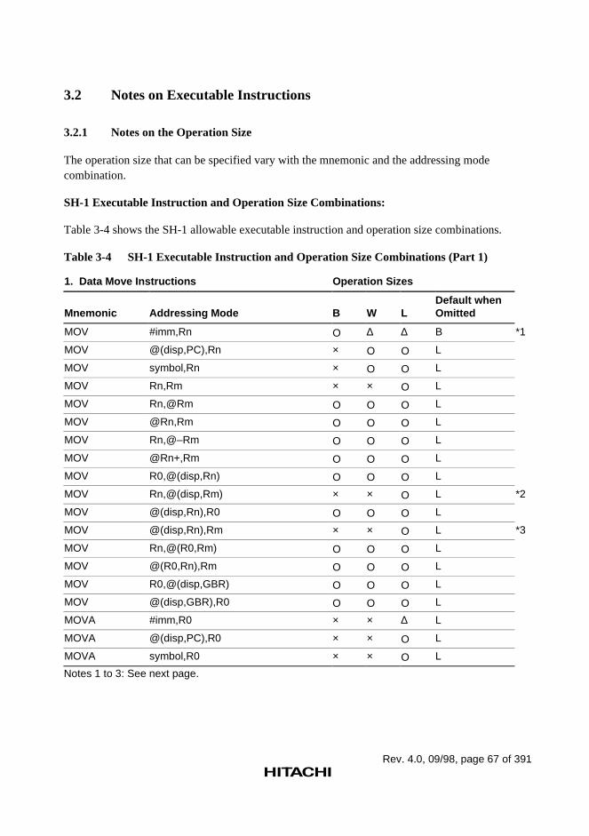
Rev. 4.0, 09/98, page 67 of 391
3.2 Notes on Executable Instructions
3.2.1 Notes on the Operation Size
The operation size that can be specified vary with the mnemonic and the addressing modecombination.
SH-1 Executable Instruction and Operation Size Combinations:
Table 3-4 shows the SH-1 allowable executable instruction and operation size combinations.
Table 3-4 SH-1 Executable Instruction and Operation Size Combinations (Part 1)
1. Data Move Instructions Operation Sizes
Mnemonic Addressing Mode B W LDefault whenOmitted
MOV #imm,Rn O ∆ ∆ B *1
MOV @(disp,PC),Rn × O O L
MOV symbol,Rn × O O L
MOV Rn,Rm × × O L
MOV Rn,@Rm O O O L
MOV @Rn,Rm O O O L
MOV Rn,@–Rm O O O L
MOV @Rn+,Rm O O O L
MOV R0,@(disp,Rn) O O O L
MOV Rn,@(disp,Rm) × × O L *2
MOV @(disp,Rn),R0 O O O L
MOV @(disp,Rn),Rm × × O L *3
MOV Rn,@(R0,Rm) O O O L
MOV @(R0,Rn),Rm O O O L
MOV R0,@(disp,GBR) O O O L
MOV @(disp,GBR),R0 O O O L
MOVA #imm,R0 × × ∆ L
MOVA @(disp,PC),R0 × × O L
MOVA symbol,R0 × × O L
Notes 1 to 3: See next page.
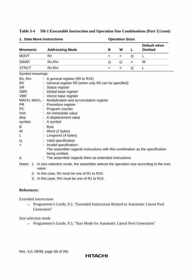
Rev. 4.0, 09/98, page 68 of 391
Table 3-4 SH-1 Executable Instruction and Operation Size Combinations (Part 1) (cont)
1. Data Move Instructions Operation Sizes
Mnemonic Addressing Mode B W LDefault whenOmitted
MOVT Rn × × O L
SWAP Rn,Rm O O × W
XTRCT Rn,Rm × × O L
Symbol meanings:Rn, Rm : A general register (R0 to R15)R0 : General register R0 (when only R0 can be specified)SR : Status registerGBR : Global base registerVBR : Vector base registerMACH, MACL : Multiplication and accumulation registerPR : Procedure registerPC : Program counterimm : An immediate valuedisp : A displacement valuesymbol : A symbolB : ByteW : Word (2 bytes)L : Longword (4 bytes)
O : Valid specification× : Invalid specification:
The assembler regards instructions with this combination as the specificationbeing omitted.
∆ : The assembler regards them as extended instructions.
Notes: 1. In size selection mode, the assembler selects the operation size according to the immvalue.
2. In this case, Rn must be one of R1 to R15.3. In this case, Rm must be one of R1 to R15.
References:
Extended instructions→ Programmer's Guide, 9.2, "Extended Instructions Related to Automatic Literal Pool
Generation"
Size selection mode→ Programmer's Guide, 9.3, "Size Mode for Automatic Literal Pool Generation"
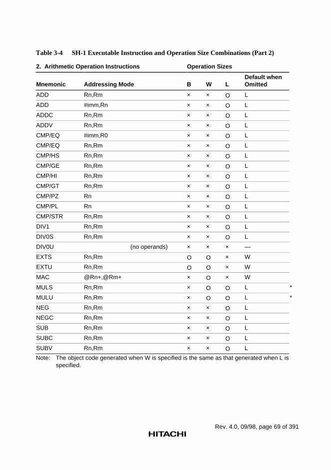
Rev. 4.0, 09/98, page 69 of 391
Table 3-4 SH-1 Executable Instruction and Operation Size Combinations (Part 2)
2. Arithmetic Operation Instructions Operation Sizes
Mnemonic Addressing Mode B W LDefault whenOmitted
ADD Rn,Rm × × O L
ADD #imm,Rn × × O L
ADDC Rn,Rm × × O L
ADDV Rn,Rm × × O L
CMP/EQ #imm,R0 × × O L
CMP/EQ Rn,Rm × × O L
CMP/HS Rn,Rm × × O L
CMP/GE Rn,Rm × × O L
CMP/HI Rn,Rm × × O L
CMP/GT Rn,Rm × × O L
CMP/PZ Rn × × O L
CMP/PL Rn × × O L
CMP/STR Rn,Rm × × O L
DIV1 Rn,Rm × × O L
DIV0S Rn,Rm × × O L
DIV0U (no operands) × × × —
EXTS Rn,Rm O O × W
EXTU Rn,Rm O O × W
MAC @Rn+,@Rm+ × O × W
MULS Rn,Rm × O O L *
MULU Rn,Rm × O O L *
NEG Rn,Rm × × O L
NEGC Rn,Rm × × O L
SUB Rn,Rm × × O L
SUBC Rn,Rm × × O L
SUBV Rn,Rm × × O L
Note: The object code generated when W is specified is the same as that generated when L isspecified.
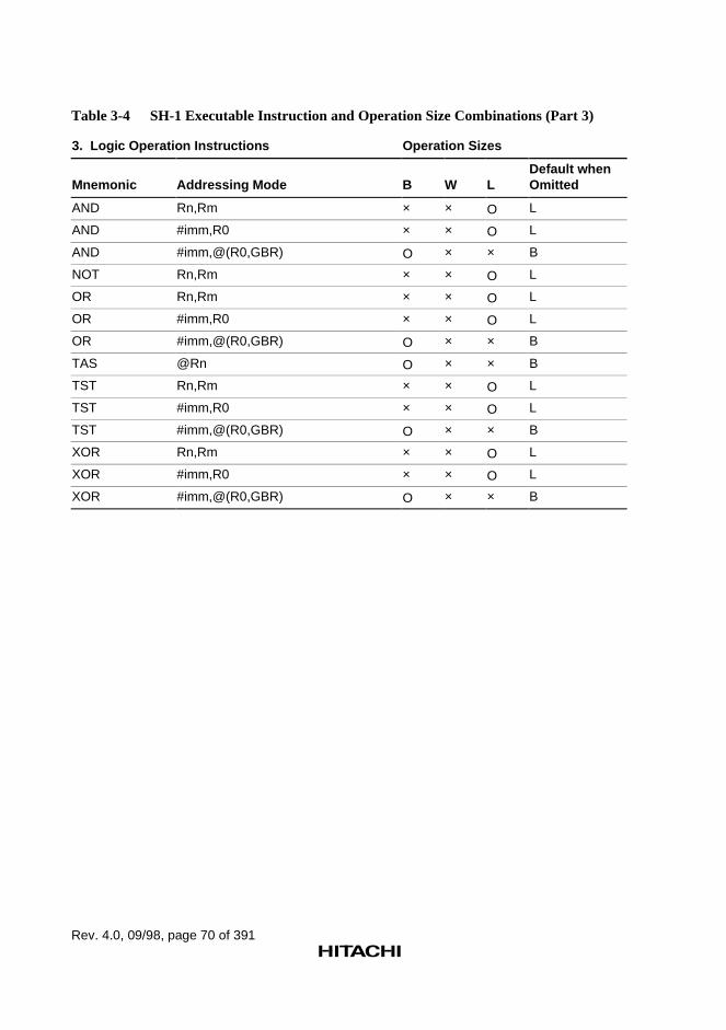
Rev. 4.0, 09/98, page 70 of 391
Table 3-4 SH-1 Executable Instruction and Operation Size Combinations (Part 3)
3. Logic Operation Instructions Operation Sizes
Mnemonic Addressing Mode B W LDefault whenOmitted
AND Rn,Rm × × O L
AND #imm,R0 × × O L
AND #imm,@(R0,GBR) O × × B
NOT Rn,Rm × × O L
OR Rn,Rm × × O L
OR #imm,R0 × × O L
OR #imm,@(R0,GBR) O × × B
TAS @Rn O × × B
TST Rn,Rm × × O L
TST #imm,R0 × × O L
TST #imm,@(R0,GBR) O × × B
XOR Rn,Rm × × O L
XOR #imm,R0 × × O L
XOR #imm,@(R0,GBR) O × × B
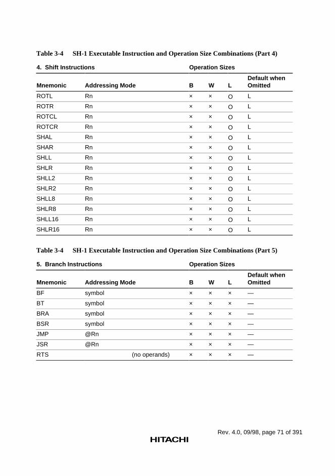
Rev. 4.0, 09/98, page 71 of 391
Table 3-4 SH-1 Executable Instruction and Operation Size Combinations (Part 4)
4. Shift Instructions Operation Sizes
Mnemonic Addressing Mode B W LDefault whenOmitted
ROTL Rn × × O L
ROTR Rn × × O L
ROTCL Rn × × O L
ROTCR Rn × × O L
SHAL Rn × × O L
SHAR Rn × × O L
SHLL Rn × × O L
SHLR Rn × × O L
SHLL2 Rn × × O L
SHLR2 Rn × × O L
SHLL8 Rn × × O L
SHLR8 Rn × × O L
SHLL16 Rn × × O L
SHLR16 Rn × × O L
Table 3-4 SH-1 Executable Instruction and Operation Size Combinations (Part 5)
5. Branch Instructions Operation Sizes
Mnemonic Addressing Mode B W LDefault whenOmitted
BF symbol × × × —
BT symbol × × × —
BRA symbol × × × —
BSR symbol × × × —
JMP @Rn × × × —
JSR @Rn × × × —
RTS (no operands) × × × —
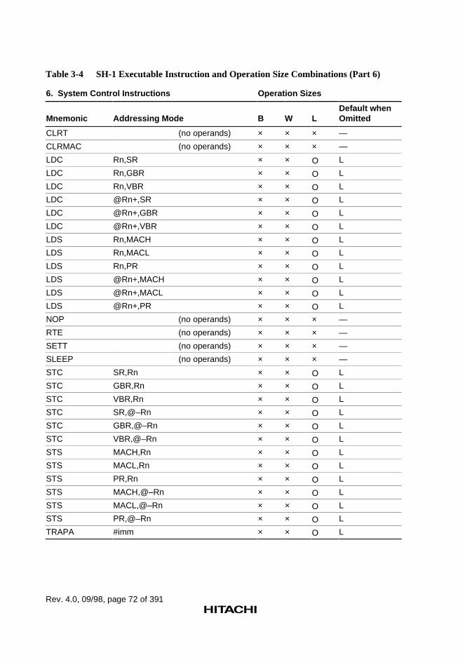
Rev. 4.0, 09/98, page 72 of 391
Table 3-4 SH-1 Executable Instruction and Operation Size Combinations (Part 6)
6. System Control Instructions Operation Sizes
Mnemonic Addressing Mode B W LDefault whenOmitted
CLRT (no operands) × × × —
CLRMAC (no operands) × × × —
LDC Rn,SR × × O L
LDC Rn,GBR × × O L
LDC Rn,VBR × × O L
LDC @Rn+,SR × × O L
LDC @Rn+,GBR × × O L
LDC @Rn+,VBR × × O L
LDS Rn,MACH × × O L
LDS Rn,MACL × × O L
LDS Rn,PR × × O L
LDS @Rn+,MACH × × O L
LDS @Rn+,MACL × × O L
LDS @Rn+,PR × × O L
NOP (no operands) × × × —
RTE (no operands) × × × —
SETT (no operands) × × × —
SLEEP (no operands) × × × —
STC SR,Rn × × O L
STC GBR,Rn × × O L
STC VBR,Rn × × O L
STC SR,@–Rn × × O L
STC GBR,@–Rn × × O L
STC VBR,@–Rn × × O L
STS MACH,Rn × × O L
STS MACL,Rn × × O L
STS PR,Rn × × O L
STS MACH,@–Rn × × O L
STS MACL,@–Rn × × O L
STS PR,@–Rn × × O L
TRAPA #imm × × O L
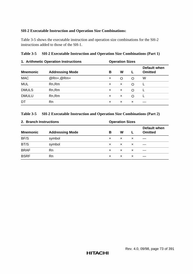
Rev. 4.0, 09/98, page 73 of 391
SH-2 Executable Instruction and Operation Size Combinations:
Table 3-5 shows the executable instruction and operation size combinations for the SH-2instructions added to those of the SH-1.
Table 3-5 SH-2 Executable Instruction and Operation Size Combinations (Part 1)
1. Arithmetic Operation Instructions Operation Sizes
Mnemonic Addressing Mode B W LDefault whenOmitted
MAC @Rn+,@Rm+ × O O W
MUL Rn,Rm × × O L
DMULS Rn,Rm × × O L
DMULU Rn,Rm × × O L
DT Rn × × × —
Table 3-5 SH-2 Executable Instruction and Operation Size Combinations (Part 2)
2. Branch Instructions Operation Sizes
Mnemonic Addressing Mode B W LDefault whenOmitted
BF/S symbol × × × —
BT/S symbol × × × —
BRAF Rn × × × —
BSRF Rn × × × —
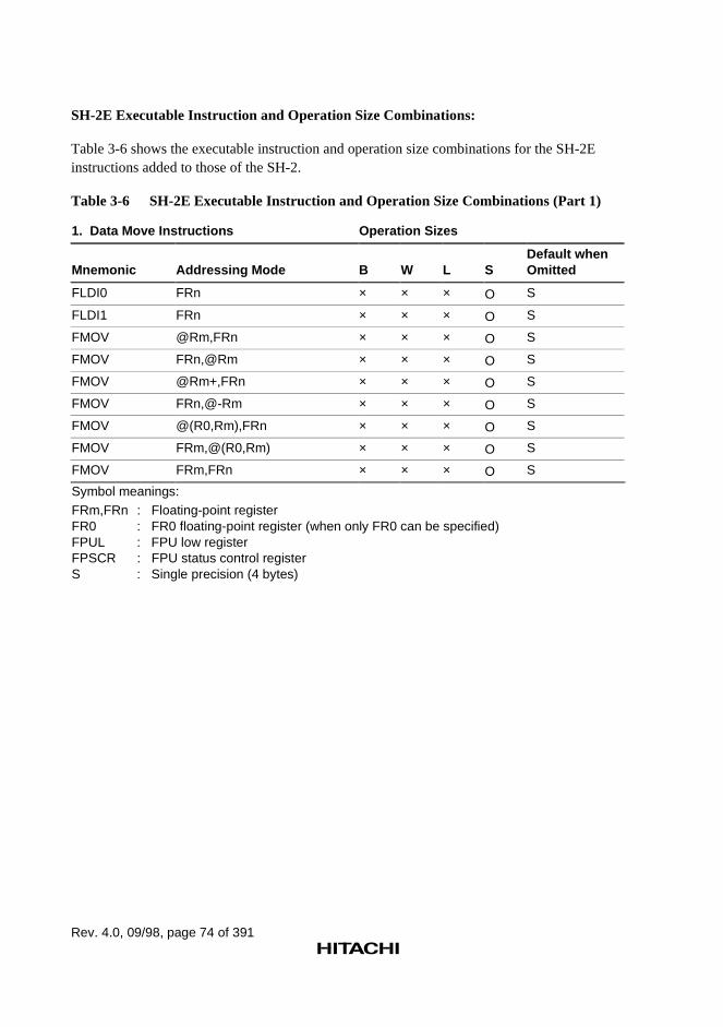
Rev. 4.0, 09/98, page 74 of 391
SH-2E Executable Instruction and Operation Size Combinations:
Table 3-6 shows the executable instruction and operation size combinations for the SH-2Einstructions added to those of the SH-2.
Table 3-6 SH-2E Executable Instruction and Operation Size Combinations (Part 1)
1. Data Move Instructions Operation Sizes
Mnemonic Addressing Mode B W L SDefault whenOmitted
FLDI0 FRn × × × O S
FLDI1 FRn × × × O S
FMOV @Rm,FRn × × × O S
FMOV FRn,@Rm × × × O S
FMOV @Rm+,FRn × × × O S
FMOV FRn,@-Rm × × × O S
FMOV @(R0,Rm),FRn × × × O S
FMOV FRm,@(R0,Rm) × × × O S
FMOV FRm,FRn × × × O S
Symbol meanings:FRm,FRn : Floating-point registerFR0 : FR0 floating-point register (when only FR0 can be specified)FPUL : FPU low registerFPSCR : FPU status control registerS : Single precision (4 bytes)
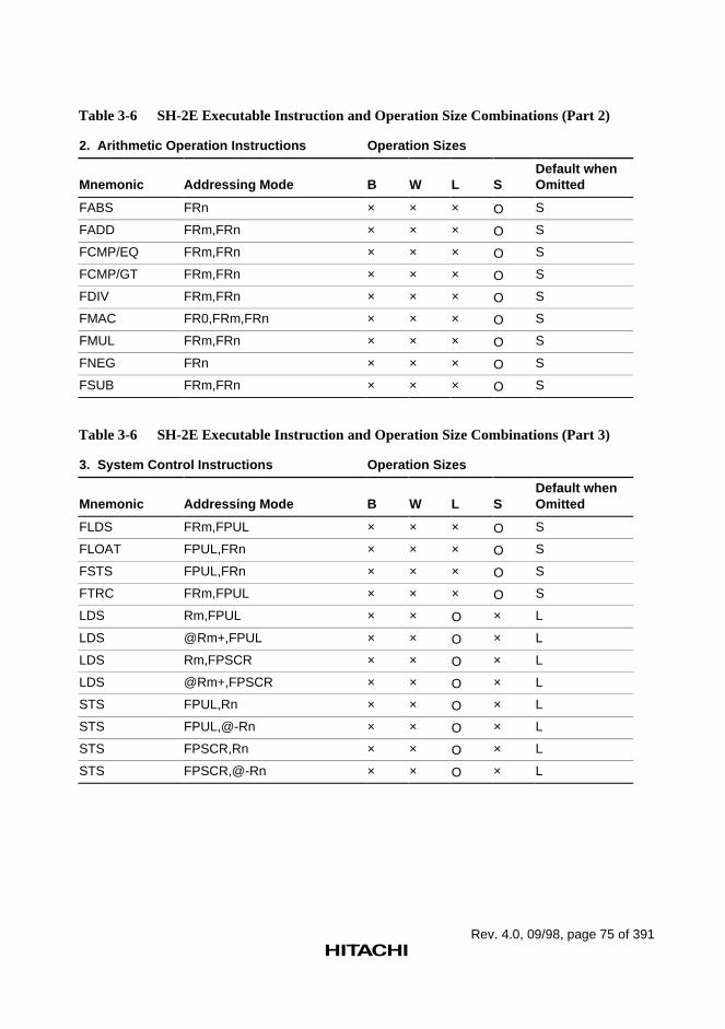
Rev. 4.0, 09/98, page 75 of 391
Table 3-6 SH-2E Executable Instruction and Operation Size Combinations (Part 2)
2. Arithmetic Operation Instructions Operation Sizes
Mnemonic Addressing Mode B W L SDefault whenOmitted
FABS FRn × × × O S
FADD FRm,FRn × × × O S
FCMP/EQ FRm,FRn × × × O S
FCMP/GT FRm,FRn × × × O S
FDIV FRm,FRn × × × O S
FMAC FR0,FRm,FRn × × × O S
FMUL FRm,FRn × × × O S
FNEG FRn × × × O S
FSUB FRm,FRn × × × O S
Table 3-6 SH-2E Executable Instruction and Operation Size Combinations (Part 3)
3. System Control Instructions Operation Sizes
Mnemonic Addressing Mode B W L SDefault whenOmitted
FLDS FRm,FPUL × × × O S
FLOAT FPUL,FRn × × × O S
FSTS FPUL,FRn × × × O S
FTRC FRm,FPUL × × × O S
LDS Rm,FPUL × × O × L
LDS @Rm+,FPUL × × O × L
LDS Rm,FPSCR × × O × L
LDS @Rm+,FPSCR × × O × L
STS FPUL,Rn × × O × L
STS FPUL,@-Rn × × O × L
STS FPSCR,Rn × × O × L
STS FPSCR,@-Rn × × O × L
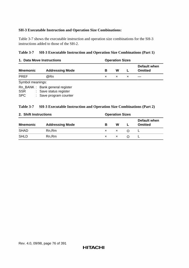
Rev. 4.0, 09/98, page 76 of 391
SH-3 Executable Instruction and Operation Size Combinations:
Table 3-7 shows the executable instruction and operation size combinations for the SH-3instructions added to those of the SH-2.
Table 3-7 SH-3 Executable Instruction and Operation Size Combinations (Part 1)
1. Data Move Instructions Operation Sizes
Mnemonic Addressing Mode B W LDefault whenOmitted
PREF @Rn × × × —
Symbol meanings:
Rn_BANK : Bank general registerSSR : Save status registerSPC : Save program counter
Table 3-7 SH-3 Executable Instruction and Operation Size Combinations (Part 2)
2. Shift Instructions Operation Sizes
Mnemonic Addressing Mode B W LDefault whenOmitted
SHAD Rn,Rm × × O L
SHLD Rn,Rm × × O L
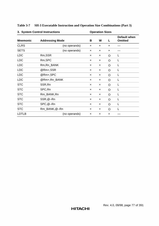
Rev. 4.0, 09/98, page 77 of 391
Table 3-7 SH-3 Executable Instruction and Operation Size Combinations (Part 3)
3. System Control Instructions Operation Sizes
Mnemonic Addressing Mode B W LDefault whenOmitted
CLRS (no operands) × × × —
SETS (no operands) × × × —
LDC Rm,SSR × × O L
LDC Rm,SPC × × O L
LDC Rm,Rn_BANK × × O L
LDC @Rm+,SSR × × O L
LDC @Rm+,SPC × × O L
LDC @Rm+,Rn_BANK × × O L
STC SSR,Rn × × O L
STC SPC,Rn × × O L
STC Rm_BANK,Rn × × O L
STC SSR,@–Rn × × O L
STC SPC,@–Rn × × O L
STC Rm_BANK,@–Rn × × O L
LDTLB (no operands) × × × —
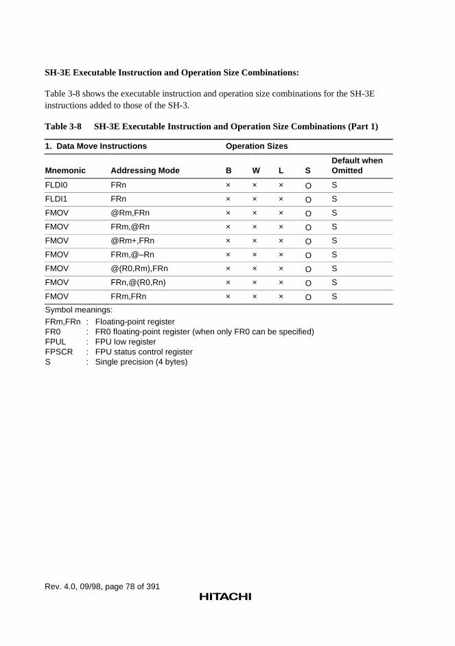
Rev. 4.0, 09/98, page 78 of 391
SH-3E Executable Instruction and Operation Size Combinations:
Table 3-8 shows the executable instruction and operation size combinations for the SH-3Einstructions added to those of the SH-3.
Table 3-8 SH-3E Executable Instruction and Operation Size Combinations (Part 1)
1. Data Move Instructions Operation Sizes
Mnemonic Addressing Mode B W L SDefault whenOmitted
FLDI0 FRn × × × O S
FLDI1 FRn × × × O S
FMOV @Rm,FRn × × × O S
FMOV FRm,@Rn × × × O S
FMOV @Rm+,FRn × × × O S
FMOV FRm,@–Rn × × × O S
FMOV @(R0,Rm),FRn × × × O S
FMOV FRn,@(R0,Rn) × × × O S
FMOV FRm,FRn × × × O S
Symbol meanings:
FRm,FRn : Floating-point registerFR0 : FR0 floating-point register (when only FR0 can be specified)FPUL : FPU low registerFPSCR : FPU status control registerS : Single precision (4 bytes)
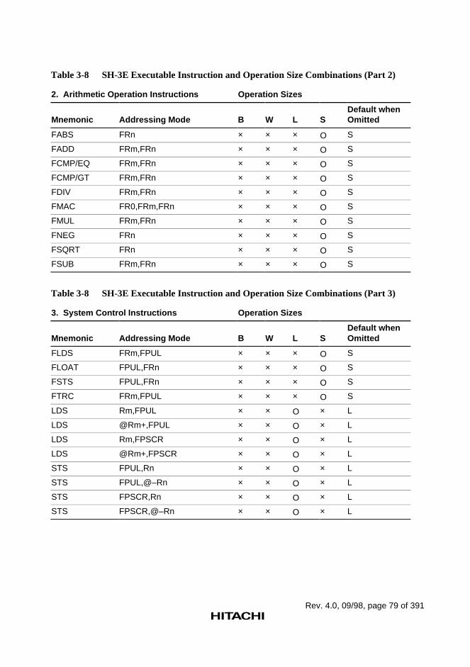
Rev. 4.0, 09/98, page 79 of 391
Table 3-8 SH-3E Executable Instruction and Operation Size Combinations (Part 2)
2. Arithmetic Operation Instructions Operation Sizes
Mnemonic Addressing Mode B W L SDefault whenOmitted
FABS FRn × × × O S
FADD FRm,FRn × × × O S
FCMP/EQ FRm,FRn × × × O S
FCMP/GT FRm,FRn × × × O S
FDIV FRm,FRn × × × O S
FMAC FR0,FRm,FRn × × × O S
FMUL FRm,FRn × × × O S
FNEG FRn × × × O S
FSQRT FRn × × × O S
FSUB FRm,FRn × × × O S
Table 3-8 SH-3E Executable Instruction and Operation Size Combinations (Part 3)
3. System Control Instructions Operation Sizes
Mnemonic Addressing Mode B W L SDefault whenOmitted
FLDS FRm,FPUL × × × O S
FLOAT FPUL,FRn × × × O S
FSTS FPUL,FRn × × × O S
FTRC FRm,FPUL × × × O S
LDS Rm,FPUL × × O × L
LDS @Rm+,FPUL × × O × L
LDS Rm,FPSCR × × O × L
LDS @Rm+,FPSCR × × O × L
STS FPUL,Rn × × O × L
STS FPUL,@–Rn × × O × L
STS FPSCR,Rn × × O × L
STS FPSCR,@–Rn × × O × L
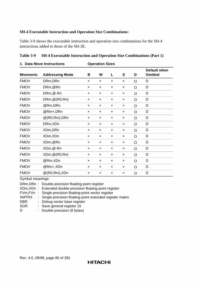
Rev. 4.0, 09/98, page 80 of 391
SH-4 Executable Instruction and Operation Size Combinations:
Table 3-9 shows the executable instruction and operation size combinations for the SH-4instructions added to those of the SH-3E.
Table 3-9 SH-4 Executable Instruction and Operation Size Combinations (Part 1)
1. Data Move Instructions Operation Sizes
Mnemonic Addressing Mode B W L S DDefault whenOmitted
FMOV DRm,DRn × × × × O D
FMOV DRm,@Rn × × × × O D
FMOV DRm,@-Rn × × × × O D
FMOV DRm,@(R0,Rn) × × × × O D
FMOV @Rm,DRn × × × × O D
FMOV @Rm+,DRn × × × × O D
FMOV @(R0,Rm),DRn × × × × O D
FMOV DRm,XDn × × × × O D
FMOV XDm,DRn × × × × O D
FMOV XDm,XDn × × × × O D
FMOV XDm,@Rn × × × × O D
FMOV XDm,@-Rn × × × × O D
FMOV XDm,@(R0,Rn) × × × × O D
FMOV @Rm,XDn × × × × O D
FMOV @Rm+,XDn × × × × O D
FMOV @(R0,Rm),XDn × × × × O D
Symbol meanings:
DRm,DRn : Double-precision floating-point registerXDm,XDn : Extended double-precision floating-point registerFVm,FVn : Single-precision floating-point vector registerXMTRX : Single-precision floating-point extended register matrixDBR : Debug vector base registerSGR : Save general register 15D : Double precision (8 bytes)
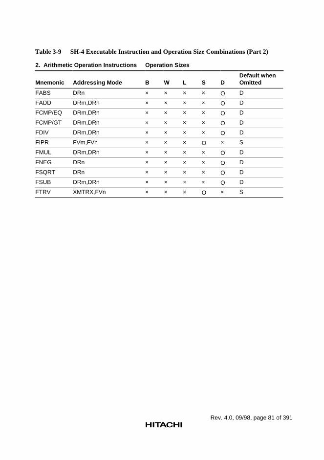
Rev. 4.0, 09/98, page 81 of 391
Table 3-9 SH-4 Executable Instruction and Operation Size Combinations (Part 2)
2. Arithmetic Operation Instructions Operation Sizes
Mnemonic Addressing Mode B W L S DDefault whenOmitted
FABS DRn × × × × O D
FADD DRm,DRn × × × × O D
FCMP/EQ DRm,DRn × × × × O D
FCMP/GT DRm,DRn × × × × O D
FDIV DRm,DRn × × × × O D
FIPR FVm,FVn × × × O × S
FMUL DRm,DRn × × × × O D
FNEG DRn × × × × O D
FSQRT DRn × × × × O D
FSUB DRm,DRn × × × × O D
FTRV XMTRX,FVn × × × O × S
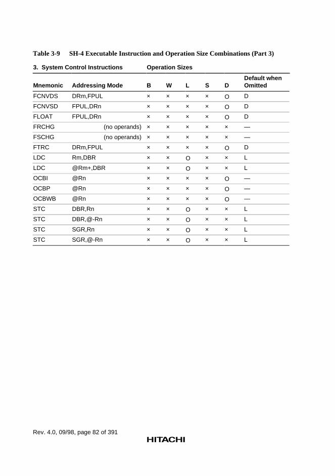
Rev. 4.0, 09/98, page 82 of 391
Table 3-9 SH-4 Executable Instruction and Operation Size Combinations (Part 3)
3. System Control Instructions Operation Sizes
Mnemonic Addressing Mode B W L S DDefault whenOmitted
FCNVDS DRm,FPUL × × × × O D
FCNVSD FPUL,DRn × × × × O D
FLOAT FPUL,DRn × × × × O D
FRCHG (no operands) × × × × × —
FSCHG (no operands) × × × × × —
FTRC DRm,FPUL × × × × O D
LDC Rm,DBR × × O × × L
LDC @Rm+,DBR × × O × × L
OCBI @Rn × × × × O —
OCBP @Rn × × × × O —
OCBWB @Rn × × × × O —
STC DBR,Rn × × O × × L
STC DBR,@-Rn × × O × × L
STC SGR,Rn × × O × × L
STC SGR,@-Rn × × O × × L
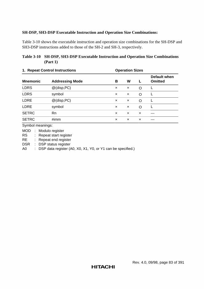
Rev. 4.0, 09/98, page 83 of 391
SH-DSP, SH3-DSP Executable Instruction and Operation Size Combinations:
Table 3-10 shows the executable instruction and operation size combinations for the SH-DSP andSH3-DSP instructions added to those of the SH-2 and SH-3, respectively.
Table 3-10 SH-DSP, SH3-DSP Executable Instruction and Operation Size Combinations(Part 1)
1. Repeat Control Instructions Operation Sizes
Mnemonic Addressing Mode B W LDefault whenOmitted
LDRS @(disp,PC) × × O L
LDRS symbol × × O L
LDRE @(disp,PC) × × O L
LDRE symbol × × O L
SETRC Rn × × × —
SETRC #imm × × × —
Symbol meanings:
MOD : Modulo registerRS : Repeat start registerRE : Repeat end registerDSR : DSP status registerA0 : DSP data register (A0, X0, X1, Y0, or Y1 can be specified.)
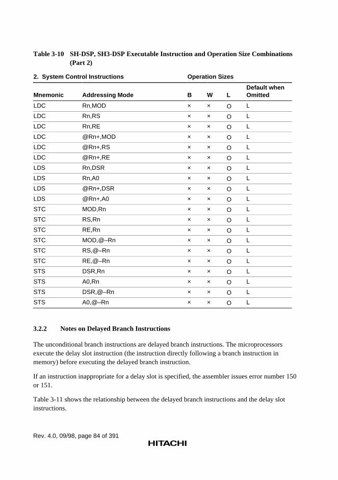
Rev. 4.0, 09/98, page 84 of 391
Table 3-10 SH-DSP, SH3-DSP Executable Instruction and Operation Size Combinations(Part 2)
2. System Control Instructions Operation Sizes
Mnemonic Addressing Mode B W LDefault whenOmitted
LDC Rn,MOD × × O L
LDC Rn,RS × × O L
LDC Rn,RE × × O L
LDC @Rn+,MOD × × O L
LDC @Rn+,RS × × O L
LDC @Rn+,RE × × O L
LDS Rn,DSR × × O L
LDS Rn,A0 × × O L
LDS @Rn+,DSR × × O L
LDS @Rn+,A0 × × O L
STC MOD,Rn × × O L
STC RS,Rn × × O L
STC RE,Rn × × O L
STC MOD,@–Rn × × O L
STC RS,@–Rn × × O L
STC RE,@–Rn × × O L
STS DSR,Rn × × O L
STS A0,Rn × × O L
STS DSR,@–Rn × × O L
STS A0,@–Rn × × O L
3.2.2 Notes on Delayed Branch Instructions
The unconditional branch instructions are delayed branch instructions. The microprocessorsexecute the delay slot instruction (the instruction directly following a branch instruction inmemory) before executing the delayed branch instruction.
If an instruction inappropriate for a delay slot is specified, the assembler issues error number 150or 151.
Table 3-11 shows the relationship between the delayed branch instructions and the delay slotinstructions.
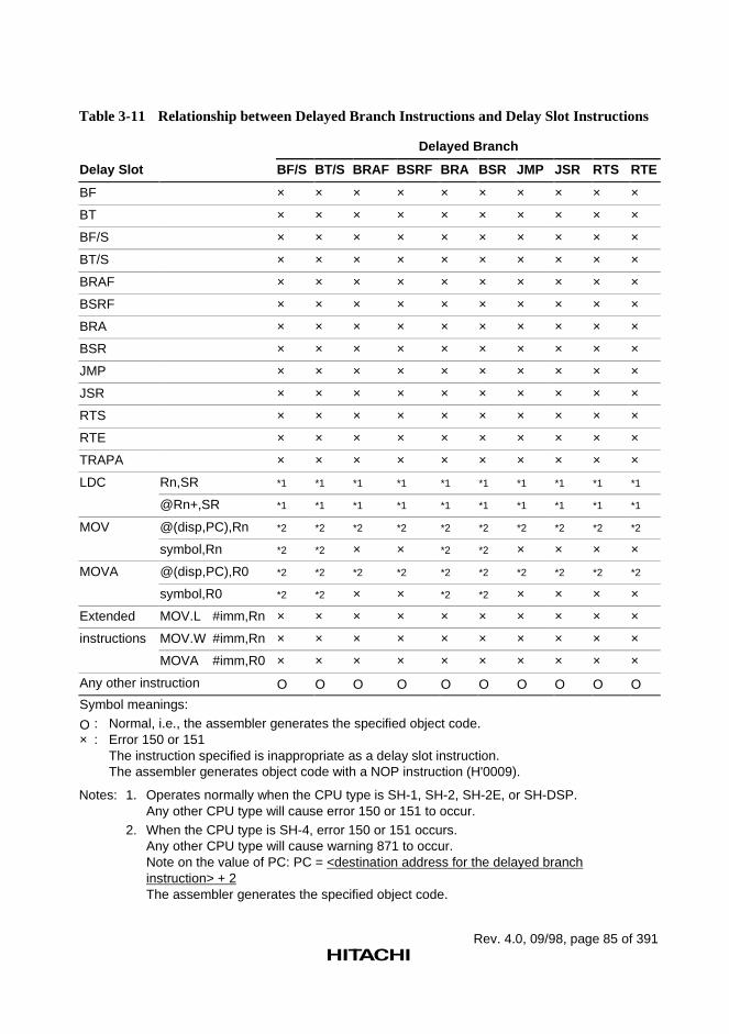
Rev. 4.0, 09/98, page 85 of 391
Table 3-11 Relationship between Delayed Branch Instructions and Delay Slot Instructions
Delayed Branch
Delay Slot BF/S BT/S BRAF BSRF BRA BSR JMP JSR RTS RTE
BF × × × × × × × × × ×
BT × × × × × × × × × ×
BF/S × × × × × × × × × ×
BT/S × × × × × × × × × ×
BRAF × × × × × × × × × ×
BSRF × × × × × × × × × ×
BRA × × × × × × × × × ×
BSR × × × × × × × × × ×
JMP × × × × × × × × × ×
JSR × × × × × × × × × ×
RTS × × × × × × × × × ×
RTE × × × × × × × × × ×
TRAPA × × × × × × × × × ×
LDC Rn,SR *1 *1 *1 *1 *1 *1 *1 *1 *1 *1
@Rn+,SR *1 *1 *1 *1 *1 *1 *1 *1 *1 *1
MOV @(disp,PC),Rn *2 *2 *2 *2 *2 *2 *2 *2 *2 *2
symbol,Rn *2 *2 × × *2 *2 × × × ×
MOVA @(disp,PC),R0 *2 *2 *2 *2 *2 *2 *2 *2 *2 *2
symbol,R0 *2 *2 × × *2 *2 × × × ×
Extended MOV.L #imm,Rn × × × × × × × × × ×
instructions MOV.W #imm,Rn × × × × × × × × × ×
MOVA #imm,R0 × × × × × × × × × ×
Any other instruction O O O O O O O O O O
Symbol meanings:
O : Normal, i.e., the assembler generates the specified object code.× : Error 150 or 151
The instruction specified is inappropriate as a delay slot instruction.The assembler generates object code with a NOP instruction (H'0009).
Notes: 1. Operates normally when the CPU type is SH-1, SH-2, SH-2E, or SH-DSP.Any other CPU type will cause error 150 or 151 to occur.
2. When the CPU type is SH-4, error 150 or 151 occurs.Any other CPU type will cause warning 871 to occur.Note on the value of PC: PC = <destination address for the delayed branchinstruction> + 2The assembler generates the specified object code.
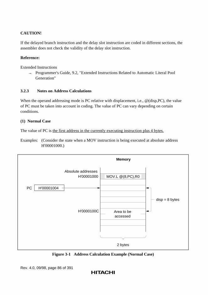
Rev. 4.0, 09/98, page 86 of 391
CAUTION!
If the delayed branch instruction and the delay slot instruction are coded in different sections, theassembler does not check the validity of the delay slot instruction.
Reference:
Extended Instructions→ Programmer's Guide, 9.2, "Extended Instructions Related to Automatic Literal Pool
Generation"
3.2.3 Notes on Address Calculations
When the operand addressing mode is PC relative with displacement, i.e., @(disp,PC), the valueof PC must be taken into account in coding. The value of PC can vary depending on certainconditions.
(1) Normal Case
The value of PC is the first address in the currently executing instruction plus 4 bytes.
Examples: (Consider the state when a MOV instruction is being executed at absolute addressH'00001000.)
H'00001004PC
H'00001000
H'0000100C
Memory
2 bytes
Absolute addresses
Area to beaccessed
disp = 8 bytes
MOV.L @(8,PC),R0
Figure 3-1 Address Calculation Example (Normal Case)
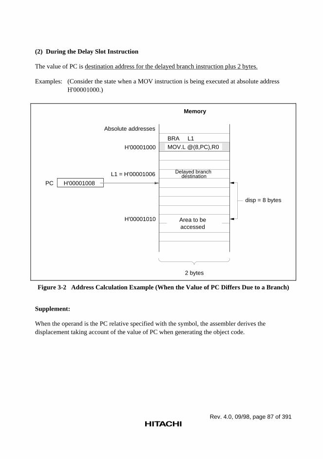
Rev. 4.0, 09/98, page 87 of 391
(2) During the Delay Slot Instruction
The value of PC is destination address for the delayed branch instruction plus 2 bytes.
Examples: (Consider the state when a MOV instruction is being executed at absolute addressH'00001000.)
H'00001000
H'00001010
Memory
2 bytes
BRA L1
H'00001008PC
L1 = H'00001006
Absolute addresses
Delayed branch destination
Area to beaccessed
disp = 8 bytes
MOV.L @(8,PC),R0
Figure 3-2 Address Calculation Example (When the Value of PC Differs Due to a Branch)
Supplement:
When the operand is the PC relative specified with the symbol, the assembler derives thedisplacement taking account of the value of PC when generating the object code.
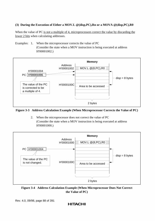
Rev. 4.0, 09/98, page 88 of 391
(3) During the Execution of Either a MOV.L @(disp,PC),Rn or a MOVA @(disp,PC),R0
When the value of PC is not a multiple of 4, microprocessors correct the value by discarding thelower 2 bits when calculating addresses.
Examples: 1. When the microprocessor corrects the value of PC(Consider the state when a MOV instruction is being executed at addressH'00001002.)
H'00001006H'00001004
PC
Memory
2 bytes
AddressH'00001002
H'0000100C Area to be accessedThe value of the PC is corrected to be a multiple of 4.
disp = 8 bytes
MOV.L @(8,PC),R0
Figure 3-3 Address Calculation Example (When Microprocessor Corrects the Value of PC)
2. When the microprocessor does not correct the value of PC(Consider the state when a MOV instruction is being executed at addressH'00001000.)
H'00001004PC
Memory
2 bytes
AddressH'00001000
H'0000100C Area to be accessed
disp = 8 bytesThe value of the PC is not changed.
MOV.L @(8,PC),R0
Figure 3-4 Address Calculation Example (When Microprocessor Does Not Correctthe Value of PC)
Rev. 4.0, 09/98, page 89 of 391
Supplement:
When the operand is the PC relative specified with the symbol, the assembler derives thedisplacement taking account of the value of PC when generating the object code.
Rev. 4.0, 09/98, page 91 of 391
Section 4 DSP Instructions
4.1 Program Contents
4.1.1 Source Statements
The SH-DSP instructions are classified into two types: executable instructions and DSPinstructions. The DSP instructions manipulate DSP registers. The instruction set and descriptionformat of DSP instructions are different from those of the executable instructions. For the DSPinstructions, many operations can be included in one statement. The DSP instruction operation isas follows:
1. DSP operation: Specifies operations between DSP registers.
PABS, PADD, PADDC, PAND, PCLR, PCMP, PCOPY, PDEC, PDMSB, PINC, PLDS,PMULS, PNEG, POR, PRND, PSHA, PSHL, PSTS, PSUB, PSUBC, PXOR
2. X data transfer operation: Specifies data transfer between a DSP register and X data memory.
MOVX, NOPX
3. Y data transfer operation: Specifies data transfer between a DSP register and Y data memory.
MOVY, NOPY
4. Single data transfer operation: Specifies data transfer between a DSP register and memory.
MOVS
Reference:
Executable instructions→ Programmer's Guide, 3, "Executable Instructions"
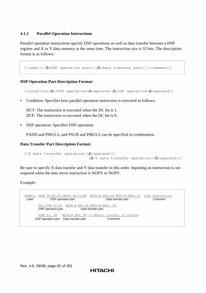
Rev. 4.0, 09/98, page 92 of 391
4.1.2 Parallel Operation Instructions
Parallel operation instructions specify DSP operations as well as data transfer between a DSPregister and X or Y data memory at the same time. The instruction size is 32 bits. The descriptionformat is as follows:
[<label>][ ∆<DSP operation part>][ ∆<data transfer part>][<comment>]
DSP Operation Part Description Format:
[<condition> ∆]<DSP operation> ∆<operand>[ ∆<DSP operation> ∆<operand>]
• Condition: Specifies how parallel operation instruction is executed as follows:
DCT: The instruction is executed when the DC bit is 1.DCF: The instruction is executed when the DC bit is 0.
• DSP operation: Specifies DSP operation.
PADD and PMULS, and PSUB and PMULS can be specified in combination.
Data Transfer Part Description Format:
[<X data transfer operation>[ ∆<operand>]][ ∆<Y data transfer operation>[ ∆<operand>]]
Be sure to specify X data transfer and Y data transfer in this order. Inputting an instruction is notrequired when the data move instruction is NOPX or NOPY.
Example:
LABEL1: PADD A0,M0,A0 PMULS X0,Y0,M0 MOVX.W @R4+,X0 MOVY.W @R6+,Y0 ;DSP Instruction
DCT PINC X1,A1 MOVX.W @R4,X0 MOVY.W @R6+, Y0
PCMP X1, M0 MOVX.W @R4, X0 ;Y Memory transfer is omitted
Label DSP operation part
DSP operation part
DSP operation part Data transfer part Comment
Data transfer part
Data transfer part Comment
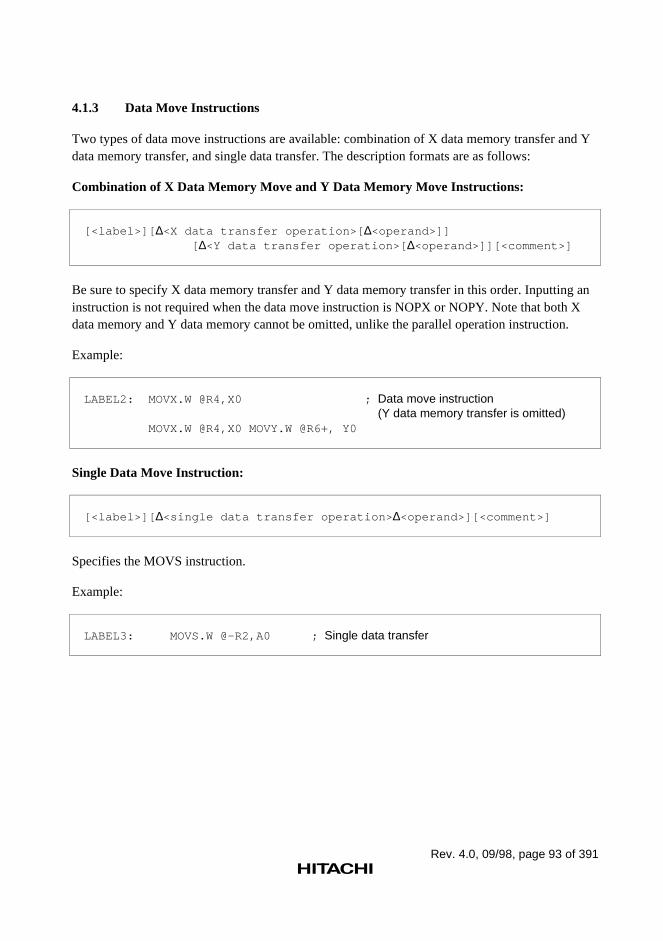
Rev. 4.0, 09/98, page 93 of 391
4.1.3 Data Move Instructions
Two types of data move instructions are available: combination of X data memory transfer and Ydata memory transfer, and single data transfer. The description formats are as follows:
Combination of X Data Memory Move and Y Data Memory Move Instructions:
[<label>][ ∆<X data transfer operation>[ ∆<operand>]][ ∆<Y data transfer operation>[ ∆<operand>]][<comment>]
Be sure to specify X data memory transfer and Y data memory transfer in this order. Inputting aninstruction is not required when the data move instruction is NOPX or NOPY. Note that both Xdata memory and Y data memory cannot be omitted, unlike the parallel operation instruction.
Example:
LABEL2: MOVX.W @R4,X0 ; Data move instruction(Y data memory transfer is omitted)
MOVX.W @R4,X0 MOVY.W @R6+, Y0
Single Data Move Instruction:
[<label>][ ∆<single data transfer operation> ∆<operand>][<comment>]
Specifies the MOVS instruction.
Example:
LABEL3: MOVS.W @-R2,A0 ; Single data transfer
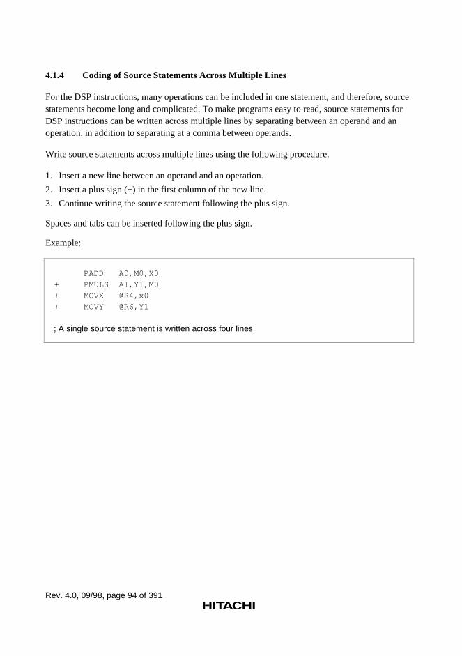
Rev. 4.0, 09/98, page 94 of 391
4.1.4 Coding of Source Statements Across Multiple Lines
For the DSP instructions, many operations can be included in one statement, and therefore, sourcestatements become long and complicated. To make programs easy to read, source statements forDSP instructions can be written across multiple lines by separating between an operand and anoperation, in addition to separating at a comma between operands.
Write source statements across multiple lines using the following procedure.
1. Insert a new line between an operand and an operation.
2. Insert a plus sign (+) in the first column of the new line.
3. Continue writing the source statement following the plus sign.
Spaces and tabs can be inserted following the plus sign.
Example:
PADD A0,M0,X0
+ PMULS A1,Y1,M0
+ MOVX @R4,x0
+ MOVY @R6,Y1
; A single source statement is written across four lines.
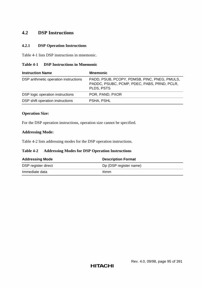
Rev. 4.0, 09/98, page 95 of 391
4.2 DSP Instructions
4.2.1 DSP Operation Instructions
Table 4-1 lists DSP instructions in mnemonic.
Table 4-1 DSP Instructions in Mnemonic
Instruction Name Mnemonic
DSP arithmetic operation instructions PADD, PSUB, PCOPY, PDMSB, PINC, PNEG, PMULS,PADDC, PSUBC, PCMP, PDEC, PABS, PRND, PCLR,PLDS, PSTS
DSP logic operation instructions POR, PAND, PXOR
DSP shift operation instructions PSHA, PSHL
Operation Size:
For the DSP operation instructions, operation size cannot be specified.
Addressing Mode:
Table 4-2 lists addressing modes for the DSP operation instructions.
Table 4-2 Addressing Modes for DSP Operation Instructions
Addressing Mode Description Format
DSP register direct Dp (DSP register name)
Immediate data #imm
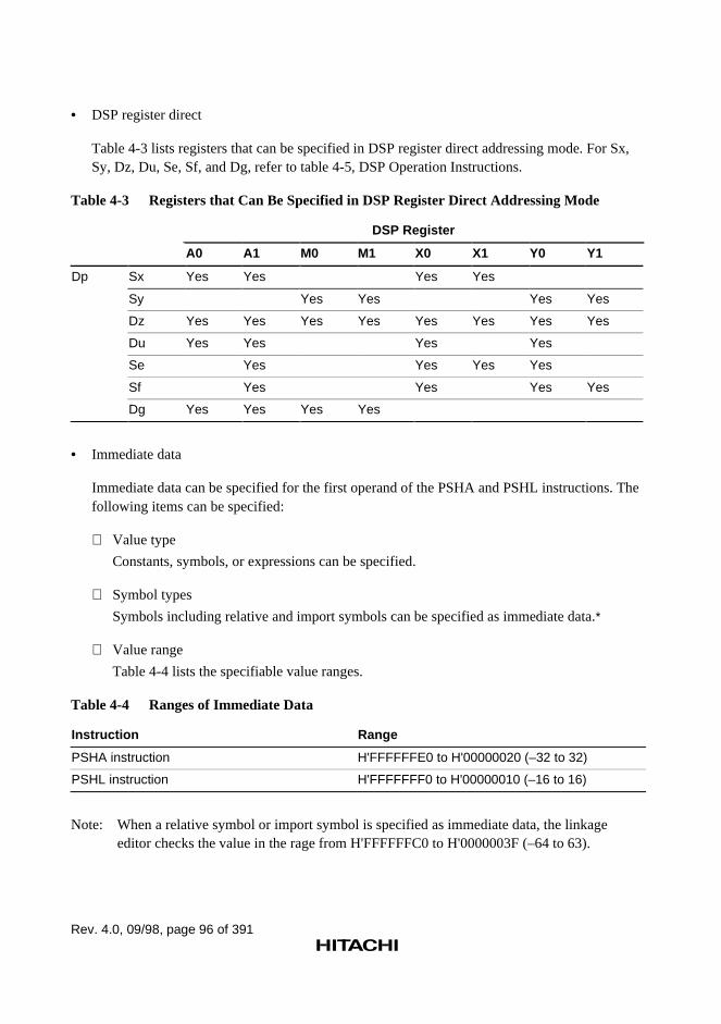
Rev. 4.0, 09/98, page 96 of 391
• DSP register direct
Table 4-3 lists registers that can be specified in DSP register direct addressing mode. For Sx,Sy, Dz, Du, Se, Sf, and Dg, refer to table 4-5, DSP Operation Instructions.
Table 4-3 Registers that Can Be Specified in DSP Register Direct Addressing Mode
DSP Register
A0 A1 M0 M1 X0 X1 Y0 Y1
Dp Sx Yes Yes Yes Yes
Sy Yes Yes Yes Yes
Dz Yes Yes Yes Yes Yes Yes Yes Yes
Du Yes Yes Yes Yes
Se Yes Yes Yes Yes
Sf Yes Yes Yes Yes
Dg Yes Yes Yes Yes
• Immediate data
Immediate data can be specified for the first operand of the PSHA and PSHL instructions. Thefollowing items can be specified:
Value type
Constants, symbols, or expressions can be specified.
Symbol types
Symbols including relative and import symbols can be specified as immediate data.*
Value range
Table 4-4 lists the specifiable value ranges.
Table 4-4 Ranges of Immediate Data
Instruction Range
PSHA instruction H'FFFFFFE0 to H'00000020 (–32 to 32)
PSHL instruction H'FFFFFFF0 to H'00000010 (–16 to 16)
Note: When a relative symbol or import symbol is specified as immediate data, the linkageeditor checks the value in the rage from H'FFFFFFC0 to H'0000003F (–64 to 63).
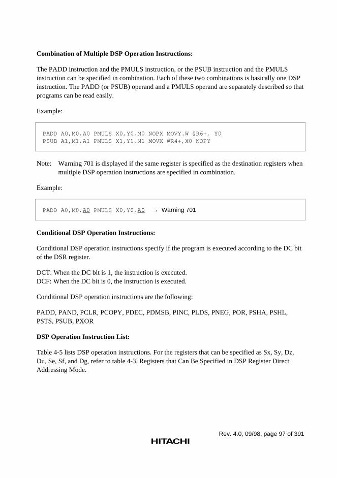
Rev. 4.0, 09/98, page 97 of 391
Combination of Multiple DSP Operation Instructions:
The PADD instruction and the PMULS instruction, or the PSUB instruction and the PMULSinstruction can be specified in combination. Each of these two combinations is basically one DSPinstruction. The PADD (or PSUB) operand and a PMULS operand are separately described so thatprograms can be read easily.
Example:
PADD A0,M0,A0 PMULS X0,Y0,M0 NOPX MOVY.W @R6+, Y0PSUB A1,M1,A1 PMULS X1,Y1,M1 MOVX @R4+,X0 NOPY
Note: Warning 701 is displayed if the same register is specified as the destination registers whenmultiple DSP operation instructions are specified in combination.
Example:
PADD A0,M0,A0 PMULS X0,Y0,A0 → Warning 701
Conditional DSP Operation Instructions:
Conditional DSP operation instructions specify if the program is executed according to the DC bitof the DSR register.
DCT: When the DC bit is 1, the instruction is executed.DCF: When the DC bit is 0, the instruction is executed.
Conditional DSP operation instructions are the following:
PADD, PAND, PCLR, PCOPY, PDEC, PDMSB, PINC, PLDS, PNEG, POR, PSHA, PSHL,PSTS, PSUB, PXOR
DSP Operation Instruction List:
Table 4-5 lists DSP operation instructions. For the registers that can be specified as Sx, Sy, Dz,Du, Se, Sf, and Dg, refer to table 4-3, Registers that Can Be Specified in DSP Register DirectAddressing Mode.
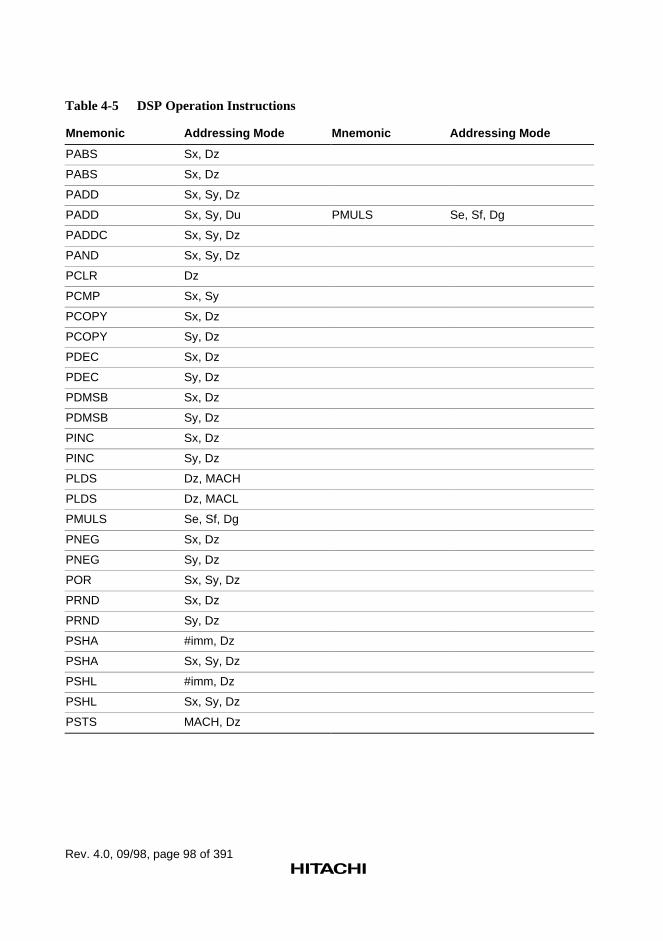
Rev. 4.0, 09/98, page 98 of 391
Table 4-5 DSP Operation Instructions
Mnemonic Addressing Mode Mnemonic Addressing Mode
PABS Sx, Dz
PABS Sx, Dz
PADD Sx, Sy, Dz
PADD Sx, Sy, Du PMULS Se, Sf, Dg
PADDC Sx, Sy, Dz
PAND Sx, Sy, Dz
PCLR Dz
PCMP Sx, Sy
PCOPY Sx, Dz
PCOPY Sy, Dz
PDEC Sx, Dz
PDEC Sy, Dz
PDMSB Sx, Dz
PDMSB Sy, Dz
PINC Sx, Dz
PINC Sy, Dz
PLDS Dz, MACH
PLDS Dz, MACL
PMULS Se, Sf, Dg
PNEG Sx, Dz
PNEG Sy, Dz
POR Sx, Sy, Dz
PRND Sx, Dz
PRND Sy, Dz
PSHA #imm, Dz
PSHA Sx, Sy, Dz
PSHL #imm, Dz
PSHL Sx, Sy, Dz
PSTS MACH, Dz
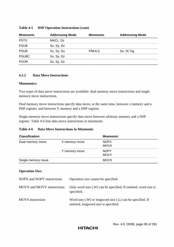
Rev. 4.0, 09/98, page 99 of 391
Table 4-5 DSP Operation Instructions (cont)
Mnemonic Addressing Mode Mnemonic Addressing Mode
PSTS MACL, Dz
PSUB Sx, Sy, Dz
PSUB Sx, Sy, Du PMULS Se, Sf, Dg
PSUBC Sx, Sy, Dz
PXOR Sx, Sy, Dz
4.2.2 Data Move Instructions
Mnemonics:
Two types of data move instructions are available: dual memory move instructions and singlememory move instructions.
Dual memory move instructions specify data move, at the same time, between x memory and aDSP register, and between Y memory and a DSP register.
Single memory move instructions specify data move between arbitrary memory and a DSPregister. Table 4-6 lists data move instructions in mnemonic.
Table 4-6 Data Move Instructions in Mnemonic
Classification Mnemonic
Dual memory move X memory move NOPXMOVX
Y memory move NOPYMOVY
Single memory move MOVS
Operation Size:
NOPX and NOPY instructions: Operation size cannot be specified.
MOVX and MOVY instructions: Only word size (.W) can be specified. If omitted, word size isspecified.
MOVS instruction: Word size (.W) or longword size (.L) can be specified. Ifomitted, longword size is specified.
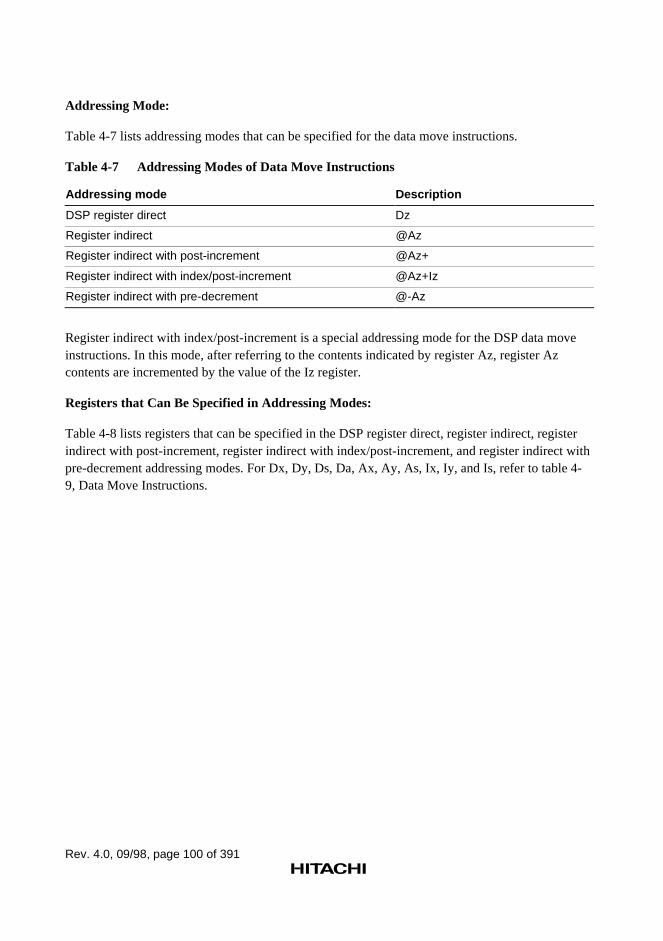
Rev. 4.0, 09/98, page 100 of 391
Addressing Mode:
Table 4-7 lists addressing modes that can be specified for the data move instructions.
Table 4-7 Addressing Modes of Data Move Instructions
Addressing mode Description
DSP register direct Dz
Register indirect @Az
Register indirect with post-increment @Az+
Register indirect with index/post-increment @Az+Iz
Register indirect with pre-decrement @-Az
Register indirect with index/post-increment is a special addressing mode for the DSP data moveinstructions. In this mode, after referring to the contents indicated by register Az, register Azcontents are incremented by the value of the Iz register.
Registers that Can Be Specified in Addressing Modes:
Table 4-8 lists registers that can be specified in the DSP register direct, register indirect, registerindirect with post-increment, register indirect with index/post-increment, and register indirect withpre-decrement addressing modes. For Dx, Dy, Ds, Da, Ax, Ay, As, Ix, Iy, and Is, refer to table 4-9, Data Move Instructions.
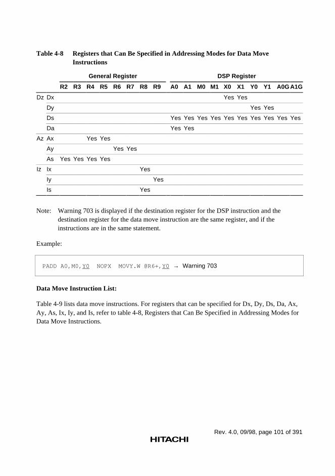
Rev. 4.0, 09/98, page 101 of 391
Table 4-8 Registers that Can Be Specified in Addressing Modes for Data MoveInstructions
General Register DSP Register
R2 R3 R4 R5 R6 R7 R8 R9 A0 A1 M0 M1 X0 X1 Y0 Y1 A0G A1G
Dz Dx Yes Yes
Dy Yes Yes
Ds Yes Yes Yes Yes Yes Yes Yes Yes Yes Yes
Da Yes Yes
Az Ax Yes Yes
Ay Yes Yes
As Yes Yes Yes Yes
Iz Ix Yes
Iy Yes
Is Yes
Note: Warning 703 is displayed if the destination register for the DSP instruction and thedestination register for the data move instruction are the same register, and if theinstructions are in the same statement.
Example:
PADD A0,M0,Y0 NOPX MOVY.W @R6+,Y0 → Warning 703
Data Move Instruction List:
Table 4-9 lists data move instructions. For registers that can be specified for Dx, Dy, Ds, Da, Ax,Ay, As, Ix, Iy, and Is, refer to table 4-8, Registers that Can Be Specified in Addressing Modes forData Move Instructions.
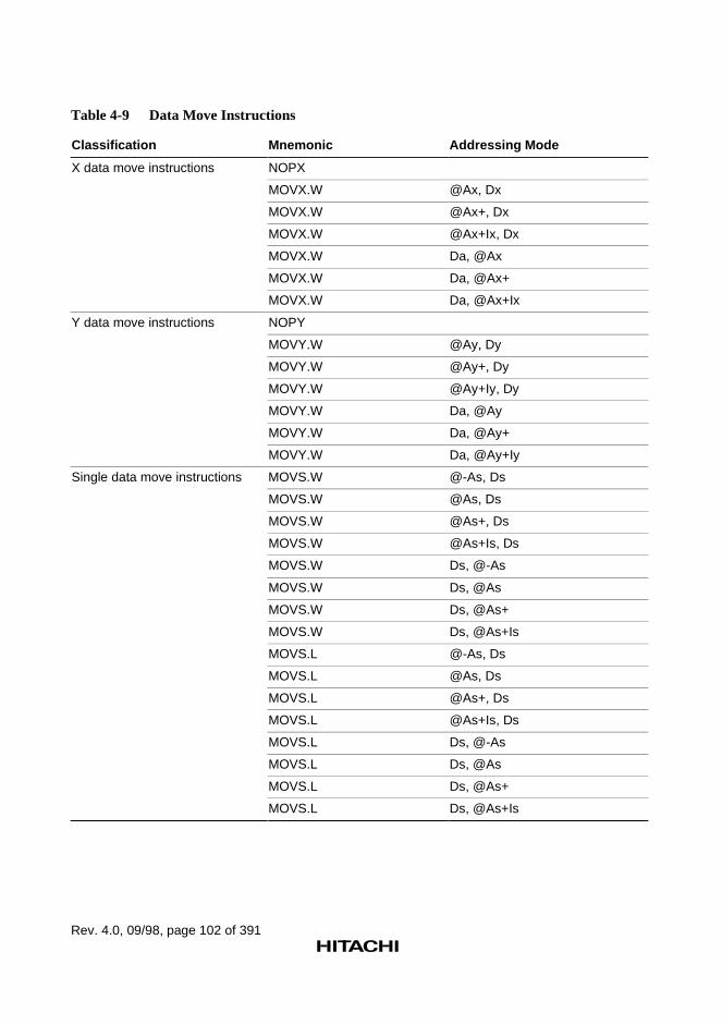
Rev. 4.0, 09/98, page 102 of 391
Table 4-9 Data Move Instructions
Classification Mnemonic Addressing Mode
X data move instructions NOPX
MOVX.W @Ax, Dx
MOVX.W @Ax+, Dx
MOVX.W @Ax+Ix, Dx
MOVX.W Da, @Ax
MOVX.W Da, @Ax+
MOVX.W Da, @Ax+Ix
Y data move instructions NOPY
MOVY.W @Ay, Dy
MOVY.W @Ay+, Dy
MOVY.W @Ay+Iy, Dy
MOVY.W Da, @Ay
MOVY.W Da, @Ay+
MOVY.W Da, @Ay+Iy
Single data move instructions MOVS.W @-As, Ds
MOVS.W @As, Ds
MOVS.W @As+, Ds
MOVS.W @As+Is, Ds
MOVS.W Ds, @-As
MOVS.W Ds, @As
MOVS.W Ds, @As+
MOVS.W Ds, @As+Is
MOVS.L @-As, Ds
MOVS.L @As, Ds
MOVS.L @As+, Ds
MOVS.L @As+Is, Ds
MOVS.L Ds, @-As
MOVS.L Ds, @As
MOVS.L Ds, @As+
MOVS.L Ds, @As+Is
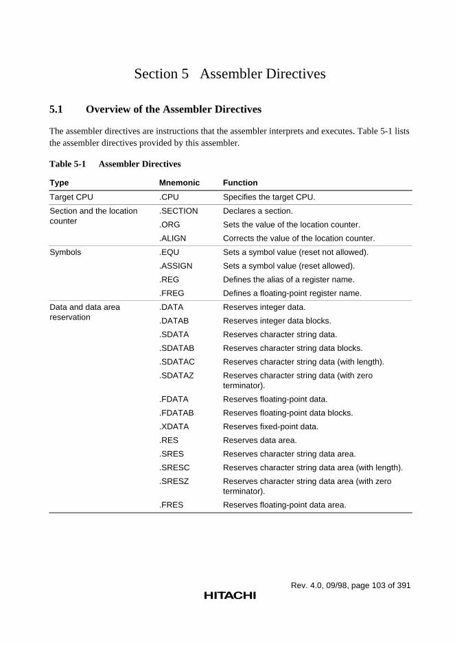
Rev. 4.0, 09/98, page 103 of 391
Section 5 Assembler Directives
5.1 Overview of the Assembler Directives
The assembler directives are instructions that the assembler interprets and executes. Table 5-1 liststhe assembler directives provided by this assembler.
Table 5-1 Assembler Directives
Type Mnemonic Function
Target CPU .CPU Specifies the target CPU.
Section and the locationcounter
.SECTION
.ORG
.ALIGN
Declares a section.
Sets the value of the location counter.
Corrects the value of the location counter.
Symbols .EQU
.ASSIGN
.REG
.FREG
Sets a symbol value (reset not allowed).
Sets a symbol value (reset allowed).
Defines the alias of a register name.
Defines a floating-point register name.
Data and data areareservation
.DATA
.DATAB
.SDATA
.SDATAB
.SDATAC
.SDATAZ
.FDATA
.FDATAB
.XDATA
.RES
.SRES
.SRESC
.SRESZ
.FRES
Reserves integer data.
Reserves integer data blocks.
Reserves character string data.
Reserves character string data blocks.
Reserves character string data (with length).
Reserves character string data (with zeroterminator).
Reserves floating-point data.
Reserves floating-point data blocks.
Reserves fixed-point data.
Reserves data area.
Reserves character string data area.
Reserves character string data area (with length).
Reserves character string data area (with zeroterminator).
Reserves floating-point data area.
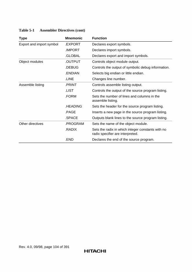
Rev. 4.0, 09/98, page 104 of 391
Table 5-1 Assembler Directives (cont)
Type Mnemonic Function
Export and import symbol .EXPORT
.IMPORT
.GLOBAL
Declares export symbols.
Declares import symbols.
Declares export and import symbols.
Object modules .OUTPUT
.DEBUG
.ENDIAN
.LINE
Controls object module output.
Controls the output of symbolic debug information.
Selects big endian or little endian.
Changes line number.
Assemble listing .PRINT
.LIST
.FORM
.HEADING
.PAGE
.SPACE
Controls assemble listing output.
Controls the output of the source program listing.
Sets the number of lines and columns in theassemble listing.
Sets the header for the source program listing.
Inserts a new page in the source program listing.
Outputs blank lines to the source program listing.
Other directives .PROGRAM
.RADIX
.END
Sets the name of the object module.
Sets the radix in which integer constants with noradix specifier are interpreted.
Declares the end of the source program.
Rev. 4.0, 09/98, page 105 of 391
5.2 Assembler Directive Reference
5.2.1 Target CPU Assembler Directive
This assemble provides the following assembler directive concerned with the target CPU.
.CPU
Specifies the target CPU.
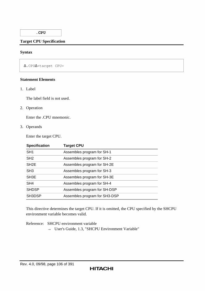
Rev. 4.0, 09/98, page 106 of 391
.CPU
Target CPU Specification
Syntax
∆.CPU∆<target CPU>
Statement Elements
1. Label
The label field is not used.
2. Operation
Enter the .CPU mnemonic.
3. Operands
Enter the target CPU.
Specification Target CPU
SH1 Assembles program for SH-1
SH2 Assembles program for SH-2
SH2E Assembles program for SH-2E
SH3 Assembles program for SH-3
SH3E Assembles program for SH-3E
SH4 Assembles program for SH-4
SHDSP Assembles program for SH-DSP
SH3DSP Assembles program for SH3-DSP
This directive determines the target CPU. If it is omitted, the CPU specified by the SHCPUenvironment variable becomes valid.
Reference: SHCPU environment variable→ User's Guide, 1.3, "SHCPU Environment Variable"
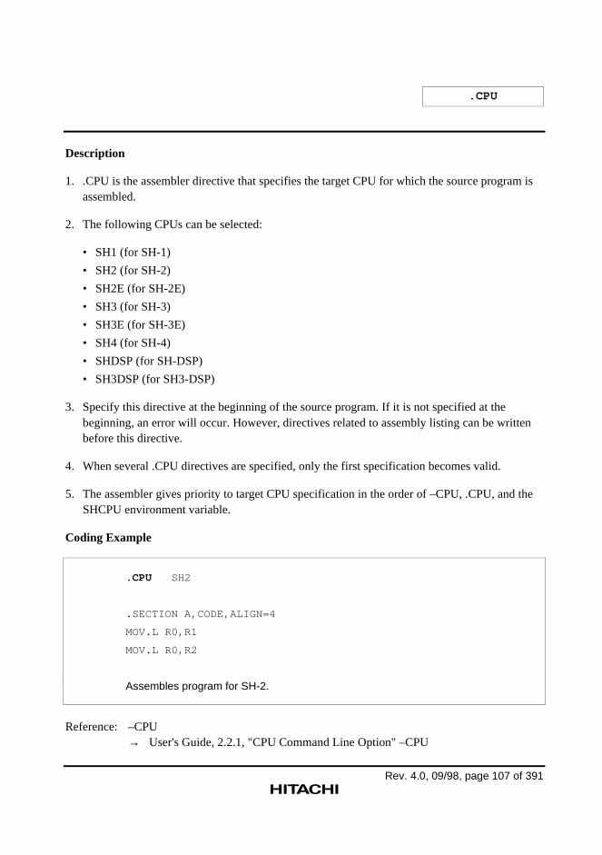
.CPU
Rev. 4.0, 09/98, page 107 of 391
Description
1. .CPU is the assembler directive that specifies the target CPU for which the source program isassembled.
2. The following CPUs can be selected:
• SH1 (for SH-1)
• SH2 (for SH-2)
• SH2E (for SH-2E)
• SH3 (for SH-3)
• SH3E (for SH-3E)
• SH4 (for SH-4)
• SHDSP (for SH-DSP)
• SH3DSP (for SH3-DSP)
3. Specify this directive at the beginning of the source program. If it is not specified at thebeginning, an error will occur. However, directives related to assembly listing can be writtenbefore this directive.
4. When several .CPU directives are specified, only the first specification becomes valid.
5. The assembler gives priority to target CPU specification in the order of –CPU, .CPU, and theSHCPU environment variable.
Coding Example
.CPU SH2
.SECTION A,CODE,ALIGN=4
MOV.L R0,R1
MOV.L R0,R2
Assembles program for SH-2.
Reference: –CPU→ User's Guide, 2.2.1, "CPU Command Line Option" –CPU
Rev. 4.0, 09/98, page 108 of 391
5.2.2 Section and Location Counter Assembler Directives
This assembler provides the following assembler directives concerned with sections and thelocation counter.
.SECTION
Declares a section.
.ORG
Sets the value of the location counter.
.ALIGN
Adjusts the value of the location counter to a multiple of the boundary alignment value.
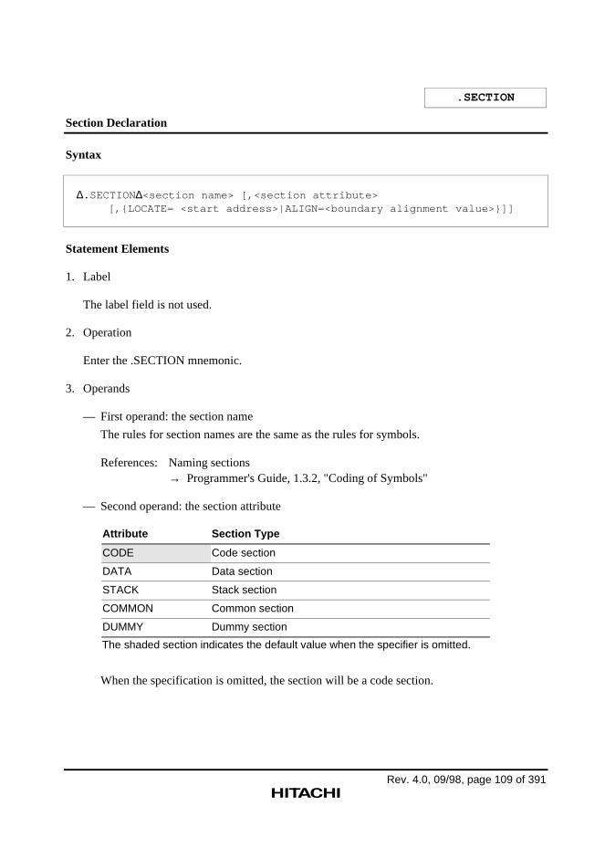
Rev. 4.0, 09/98, page 109 of 391
.SECTION
Section Declaration
Syntax
∆.SECTION∆<section name> [,<section attribute>[,{LOCATE= <start address>|ALIGN=<boundary alignment value>}]]
Statement Elements
1. Label
The label field is not used.
2. Operation
Enter the .SECTION mnemonic.
3. Operands
— First operand: the section name
The rules for section names are the same as the rules for symbols.
References: Naming sections→ Programmer's Guide, 1.3.2, "Coding of Symbols"
— Second operand: the section attribute
Attribute Section Type
CODE Code section
DATA Data section
STACK Stack section
COMMON Common section
DUMMY Dummy section
The shaded section indicates the default value when the specifier is omitted.
When the specification is omitted, the section will be a code section.
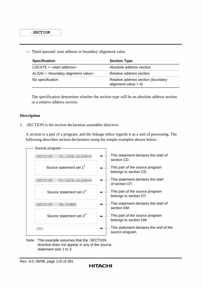
.SECTION
Rev. 4.0, 09/98, page 110 of 391
— Third operand: start address or boundary alignment value
Specification Section Type
LOCATE = <start address> Absolute address section
ALIGN = <boundary alignment value> Relative address section
No specification Relative address section (boundaryalignment value = 4)
The specification determines whether the section type will be an absolute address sectionor a relative address section.
Description
1. .SECTION is the section declaration assembler directive.
A section is a part of a program, and the linkage editor regards it as a unit of processing. Thefollowing describes section declaration using the simple examples shown below.
.END
.SECTION DT,DATA,ALIGN=4
.SECTION DM,DUMMY
Source program
.SECTION CD,CODE,ALIGN=4
Source statement set 1*
*
*
Source statement set 2
Source statement set 3
This statement declares the start of section CD.
This part of the source program belongs to section CD.
This statement declares the start of section DT.
This part of the source program belongs to section DT.
This statement declares the start of section DM.
This part of the source program belongs to section DM.
This statement declares the end of the source program.
Note: This example assumes that the .SECTIONdirective does not appear in any of the source statement sets 1 to 3.
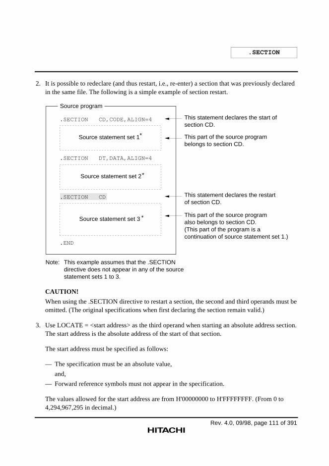
.SECTION
Rev. 4.0, 09/98, page 111 of 391
2. It is possible to redeclare (and thus restart, i.e., re-enter) a section that was previously declaredin the same file. The following is a simple example of section restart.
.END
.SECTION DT,DATA,ALIGN=4
.SECTION CD
Source program
.SECTION CD,CODE,ALIGN=4
Source statement set 1*
*
*
Source statement set 2
Source statement set 3
Note: This example assumes that the .SECTIONdirective does not appear in any of the sourcestatement sets 1 to 3.
This statement declares the start of section CD.
This part of the source program belongs to section CD.
This statement declares the restart of section CD.
This part of the source program also belongs to section CD. (This part of the program is a continuation of source statement set 1.)
CAUTION!
When using the .SECTION directive to restart a section, the second and third operands must beomitted. (The original specifications when first declaring the section remain valid.)
3. Use LOCATE = <start address> as the third operand when starting an absolute address section.The start address is the absolute address of the start of that section.
The start address must be specified as follows:
— The specification must be an absolute value,
and,
— Forward reference symbols must not appear in the specification.
The values allowed for the start address are from H'00000000 to H'FFFFFFFF. (From 0 to4,294,967,295 in decimal.)
.SECTION
Rev. 4.0, 09/98, page 112 of 391
4. Use ALIGN = <boundary alignment value> to start a relative address section. The linkageeditor will adjust the start address of the section to be a multiple of the boundary alignmentvalue.
The boundary alignment value must be specified as follows:
— The specification must be an absolute value,
and,
— Forward reference symbols must not appear in the specification.
The values allowed for the boundary alignment value are powers of 2, e.g. 20, 21, 22, ..., 231.For code sections, the values must be 4 or larger powers of 2, e.g. 22, 23, 24, ..., 231.
5. The assembler provides a default section for the following cases:
— The use of executable or extended instructions when no section has been declared.
— The use of data reservation assembler directives when no section has been declared.
— The use of the .ALIGN directive when no section has been declared.
— The use of the .ORG directive when no section has been declared.
— Reference to the location counter when no section has been declared.
— The use of statements consisting of only the label field when no section has been declared.
The default section is the following section:
— Section name: P
— Section type: Code section
Relative address section (with a boundary alignment value of 4)
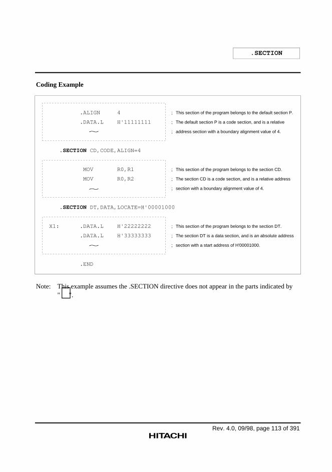
.SECTION
Rev. 4.0, 09/98, page 113 of 391
Coding Example
.ALIGN 4
.DATA.L H'11111111
.SECTION CD,CODE,ALIGN=4
MOV R0,R1
MOV R0,R2
.SECTION DT,DATA,LOCATE=H'00001000
X1: .DATA.L H'22222222
.DATA.L H'33333333
.END
; This section of the program belongs to the default section P.
; The default section P is a code section, and is a relative
; address section with a boundary alignment value of 4.
; This section of the program belongs to the section CD.
; The section CD is a code section, and is a relative address
; section with a boundary alignment value of 4.
; This section of the program belongs to the section DT.
; The section DT is a data section, and is an absolute address
; section with a start address of H'00001000.
~
~
~
Note: This example assumes the .SECTION directive does not appear in the parts indicated by"∼".
Rev. 4.0, 09/98, page 114 of 391
.ORG
Location-Counter-Value Setting
Syntax
∆.ORG∆<location-counter-value>
Statement Elements
1. Label
The label field is not used.
2. Operation
Enter the .ORG mnemonic.
3. Operands
Enter the new value for the location counter.
Description
1. .ORG is the assembler directive that sets the value of the location counter. The .ORG directiveis used to place executable instructions or data at a specific address.
2. The location-counter-value must be specified as follows:
— The specification must be an absolute value or an address within the section,
and,
— Forward reference symbols must not appear in the specification.
The values allowed for the location-counter-value are from H'00000000 to H'FFFFFFFF.(From 0 to 4,294,967,295 in decimal.)
When the location-counter-value is specified with an absolute value, the following conditionmust be satisfied:
<location-counter-value> ≥ <section start address> (when compared as unsigned values)
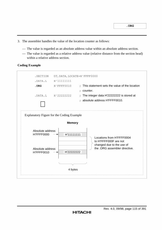
.ORG
Rev. 4.0, 09/98, page 115 of 391
3. The assembler handles the value of the location counter as follows:
— The value is regarded as an absolute address value within an absolute address section.
— The value is regarded as a relative address value (relative distance from the section head)within a relative address section.
Coding Example
.SECTION DT,DATA,LOCATE=H'FFFF0000
.DATA.L H'11111111
.ORG H'FFFF0010 ; This statement sets the value of the location
; counter.
.DATA.L H'22222222 ; The integer data H'22222222 is stored at
; absolute address H'FFFF0010.
∼
Memory
4 bytes
Absolute address H’FFFF0000
Absolute address H’FFFF0010
Locations from H’FFFF0004 to H’FFFF000F are not changed due to the use of the .ORG assembler directive.
H'11111111
H'22222222
Explanatory Figure for the Coding Example
Rev. 4.0, 09/98, page 116 of 391
.ALIGN
Location-Counter-Value Correction
Syntax
∆.ALIGN ∆<boundary alignment value>
Statement Elements
1. Label
The label field is not used.
2. Operation
Enter the .ALIGN mnemonic.
3. Operands
Enter the boundary alignment value.
Description
1. .ALIGN is the assembler directive that corrects the location-counter-value to be a multiple ofthe boundary alignment value. Executable instructions and data can be allocated on specificboundary values (address multiples) by using the .ALIGN directive.
2. The boundary alignment value must be specified as follows:
— The specification must be an absolute value,
and,
— Forward reference symbols must not appear in the specification.
The values allowed for the boundary alignment value are powers of 2, e.g. 20, 21, 22, ..., 231.
3. When .ALIGN is used in a relative section the following must be satisfied:
Boundary alignment value specified by .SECTION ≥ Boundary alignment value specified by.ALIGN
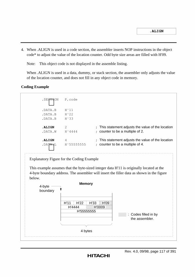
.ALIGN
Rev. 4.0, 09/98, page 117 of 391
4. When .ALIGN is used in a code section, the assembler inserts NOP instructions in the objectcode* to adjust the value of the location counter. Odd byte size areas are filled with H'09.
Note: This object code is not displayed in the assemble listing.
When .ALIGN is used in a data, dummy, or stack section, the assembler only adjusts the valueof the location counter, and does not fill in any object code in memory.
Coding Example
.SECTION P,code ∼ .DATA.B H'11 .DATA.B H'22 .DATA.B H'33
. ALIGN 2 ; This statement adjusts the value of the location .DATA.W H'4444 ; counter to be a multiple of 2.
. ALIGN 4 ; This statement adjusts the value of the location .DATA.L H'55555555 ; counter to be a multiple of 4. ∼
H'11 H'22 H'33H'4444
H'55555555
Memory4-byte boundary
4 bytes
: Codes filled in by the assembler.
H'09H'0009
Explanatory Figure for the Coding Example
This example assumes that the byte-sized integer data H'11 is originally located at the 4-byte boundary address. The assembler will insert the filler data as shown in the figure below.
Rev. 4.0, 09/98, page 118 of 391
5.2.3 Symbol Handling Assembler Directives
This assembler provides the following assembler directives concerned with symbols.
.EQU
Sets a symbol value.
.ASSIGN
Sets and resets a symbol value.
.REG
Defines the alias of a register name.
.FREG
Defines a floating-point register name.
Rev. 4.0, 09/98, page 119 of 391
.EQU
Symbol Value Setting (Resetting Not Allowed)
Syntax
<symbol>[:] ∆.EQU∆<symbol value>
Statement Elements
1. Label
Enter the symbol to which a value is to be set.
2. Operation
Enter the .EQU mnemonic.
3. Operands
Enter the value to be set to the symbol.
Description
1. .EQU is the assembler directive that sets a value to a symbol.
Symbols defined with the .EQU directive cannot be redefined.
2. The symbol value must be specified as follows:
— The specification must be an absolute value, an address value, or an import symbol value*
and,
— Forward reference symbols must not appear in the specification.
The values allowed for the symbol value are from H'00000000 to H'FFFFFFFF.(From -2,147,483,648 to 4,294,967,295 in decimal.)
Note: An import value, import value + constant, or import value – constant can be specified.
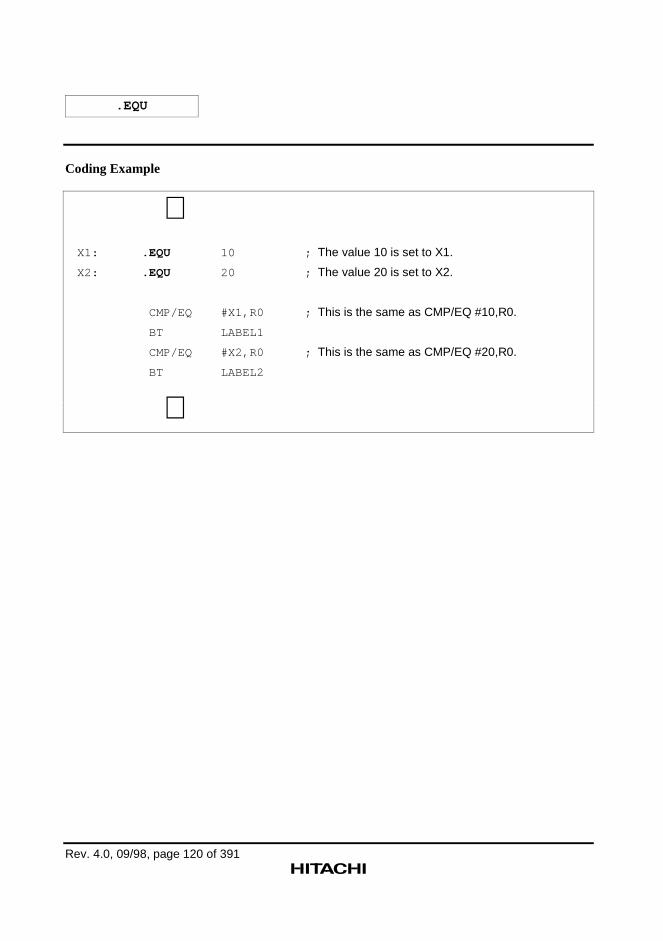
.EQU
Rev. 4.0, 09/98, page 120 of 391
Coding Example
∼X1: .EQU 10 ; The value 10 is set to X1.
X2: .EQU 20 ; The value 20 is set to X2.
CMP/EQ #X1,R0 ; This is the same as CMP/EQ #10,R0.
BT LABEL1
CMP/EQ #X2,R0 ; This is the same as CMP/EQ #20,R0.
BT LABEL2
∼
Rev. 4.0, 09/98, page 121 of 391
.ASSIGN
Symbol Value Setting (Resetting Allowed)
Syntax
<symbol>[:] ∆.ASSIGN ∆<symbol value>
Statement Elements
1. Label
Enter the symbol to which a value is to be set.
2. Operation
Enter the .ASSIGN mnemonic.
3. Operands
Enter the value to be set to the symbol.
Description
1. .ASSIGN is the assembler directive that sets a value to a symbol.
Symbols defined with the .ASSIGN directive can be redefined with the .ASSIGN directive.
2. The symbol value must be specified as follows:
— The specification must be an absolute value or an address value,
and,
— Forward reference symbols must not appear in the specification.
The values allowed for the symbol value are from H'00000000 to H'FFFFFFFF. (From 0 to4,294,967,295 in decimal.)
3. Definitions with the .ASSIGN directive are valid from the point of the definition forward inthe program.
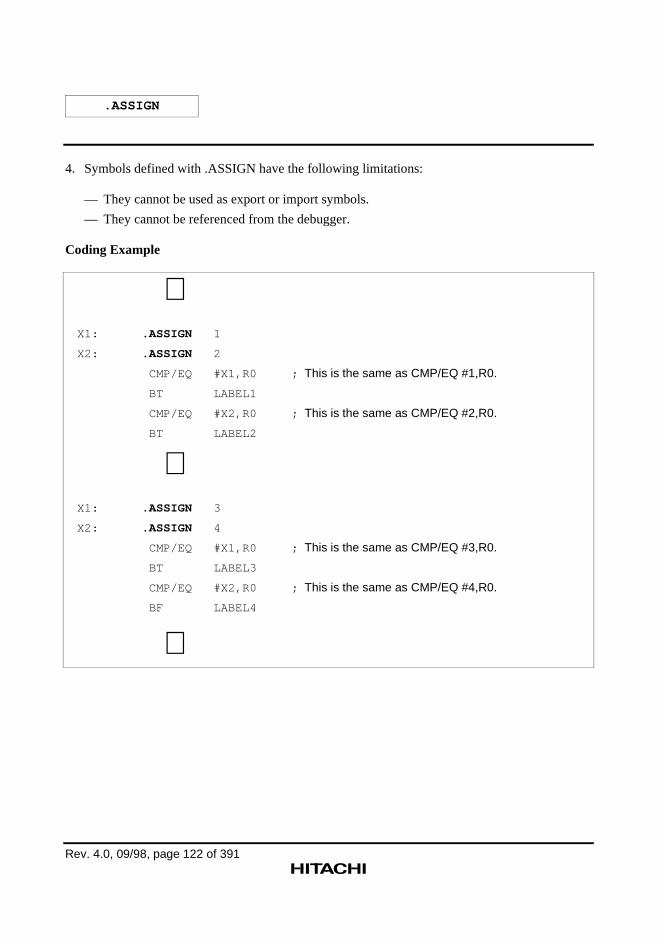
.ASSIGN
Rev. 4.0, 09/98, page 122 of 391
4. Symbols defined with .ASSIGN have the following limitations:
— They cannot be used as export or import symbols.
— They cannot be referenced from the debugger.
Coding Example
∼X1: .ASSIGN 1
X2: .ASSIGN 2
CMP/EQ #X1,R0 ; This is the same as CMP/EQ #1,R0.
BT LABEL1
CMP/EQ #X2,R0 ; This is the same as CMP/EQ #2,R0.
BT LABEL2
∼X1: .ASSIGN 3
X2: .ASSIGN 4
CMP/EQ #X1,R0 ; This is the same as CMP/EQ #3,R0.
BT LABEL3
CMP/EQ #X2,R0 ; This is the same as CMP/EQ #4,R0.
BF LABEL4
∼
Rev. 4.0, 09/98, page 123 of 391
.REG
Register Name Alias Definition
Syntax
<symbol>[:] ∆.REG∆<register name> or<symbol>[:] ∆.REG∆(<register name>)
Statement Elements
1. Label
Enter the symbol to be defined as the alias of a register name.
2. Operation
Enter the .REG mnemonic.
3. Operands
Enter the register name for which the alias of a register name is being defined.
Description
1. .REG is the assembler directive that defines the alias of a register name.
The alias of a register name defined with .REG can be used in exactly the same manner as theoriginal register name.
The alias of a register name defined with .REG cannot be redefined.
2. The alias of a register name can only be defined for the general registers (R0 to R15, and SP).
3. Definitions with the .REG directive are valid from the point of the definition forward in theprogram.
4. Symbols defined with .REG have the following limitations:
— They cannot be used as import or export symbols.
— They cannot be referenced from the simulator/debugger.
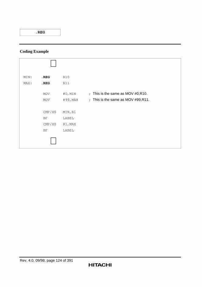
.REG
Rev. 4.0, 09/98, page 124 of 391
Coding Example
∼MIN: .REG R10
MAX: .REG R11
MOV #0,MIN ; This is the same as MOV #0,R10.
MOV #99,MAX ; This is the same as MOV #99,R11.
CMP/HS MIN,R1
BF LABEL
CMP/HS R1,MAX
BF LABEL
∼
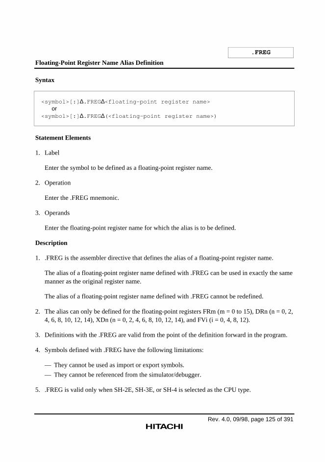
Rev. 4.0, 09/98, page 125 of 391
.FREG
Floating-Point Register Name Alias Definition
Syntax
<symbol>[:] ∆.FREG∆<floating-point register name> or<symbol>[:] ∆.FREG∆(<floating-point register name>)
Statement Elements
1. Label
Enter the symbol to be defined as a floating-point register name.
2. Operation
Enter the .FREG mnemonic.
3. Operands
Enter the floating-point register name for which the alias is to be defined.
Description
1. .FREG is the assembler directive that defines the alias of a floating-point register name.
The alias of a floating-point register name defined with .FREG can be used in exactly the samemanner as the original register name.
The alias of a floating-point register name defined with .FREG cannot be redefined.
2. The alias can only be defined for the floating-point registers FRm (m = 0 to 15), DRn (n = 0, 2,4, 6, 8, 10, 12, 14), XDn (n = 0, 2, 4, 6, 8, 10, 12, 14), and FVi (i = 0, 4, 8, 12).
3. Definitions with the .FREG are valid from the point of the definition forward in the program.
4. Symbols defined with .FREG have the following limitations:
— They cannot be used as import or export symbols.
— They cannot be referenced from the simulator/debugger.
5. .FREG is valid only when SH-2E, SH-3E, or SH-4 is selected as the CPU type.
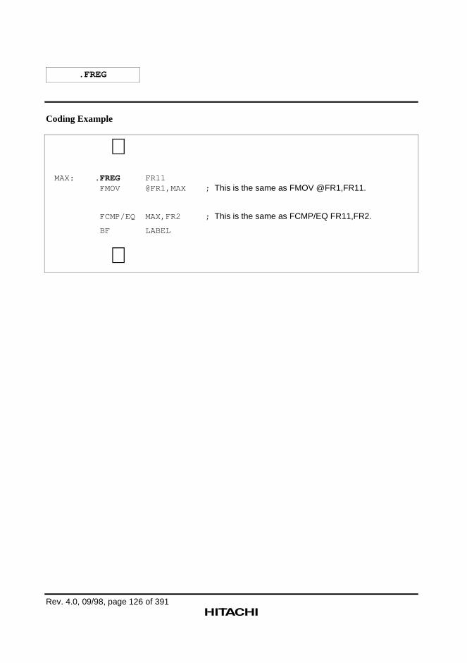
.FREG
Rev. 4.0, 09/98, page 126 of 391
Coding Example
∼MAX: .FREG FR11 FMOV @FR1,MAX ; This is the same as FMOV @FR1,FR11.
FCMP/EQ MAX,FR2 ; This is the same as FCMP/EQ FR11,FR2.
BF LABEL
∼
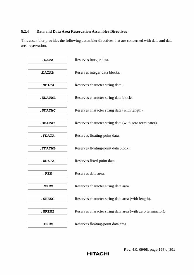
Rev. 4.0, 09/98, page 127 of 391
5.2.4 Data and Data Area Reservation Assembler Directives
This assembler provides the following assembler directives that are concerned with data and dataarea reservation.
.DATA Reserves integer data.
.DATAB Reserves integer data blocks.
.SDATA Reserves character string data.
.SDATAB Reserves character string data blocks.
.SDATAC Reserves character string data (with length).
.SDATAZ Reserves character string data (with zero terminator).
.FDATA Reserves floating-point data.
.FDATAB Reserves floating-point data block.
.XDATA Reserves fixed-point data.
.RES Reserves data area.
.SRES Reserves character string data area.
.SRESC Reserves character string data area (with length).
.SRESZ Reserves character string data area (with zero terminator).
.FRES Reserves floating-point data area.
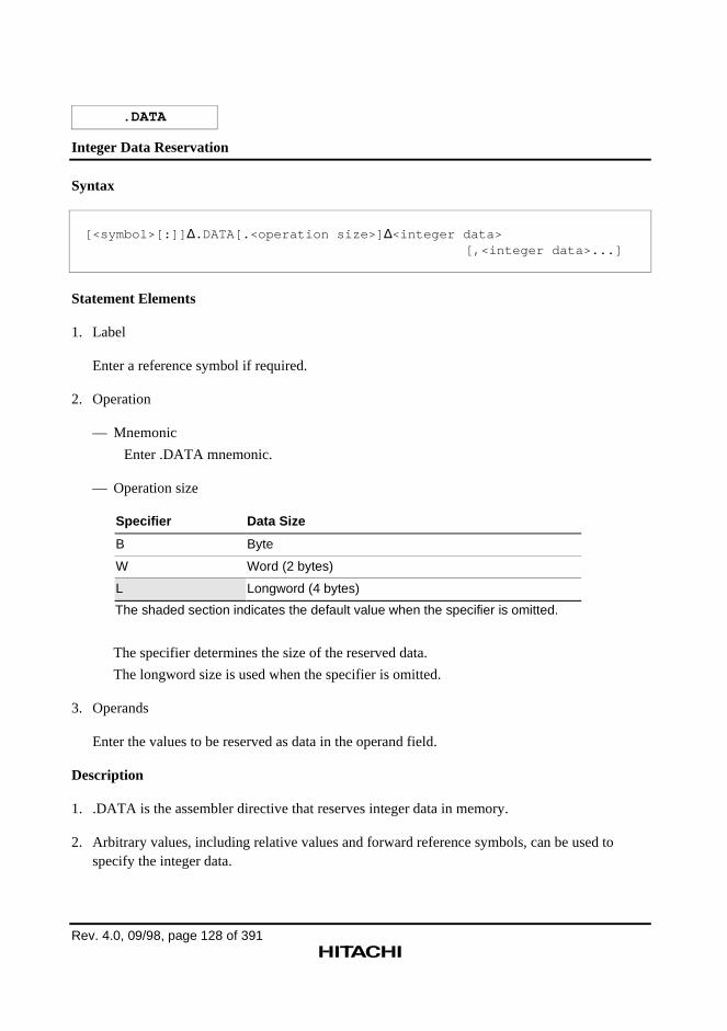
Rev. 4.0, 09/98, page 128 of 391
.DATA
Integer Data Reservation
Syntax
[<symbol>[:]] ∆.DATA[.<operation size>] ∆<integer data>[,<integer data>...]
Statement Elements
1. Label
Enter a reference symbol if required.
2. Operation
— Mnemonic
Enter .DATA mnemonic.
— Operation size
Specifier Data Size
B Byte
W Word (2 bytes)
L Longword (4 bytes)
The shaded section indicates the default value when the specifier is omitted.
The specifier determines the size of the reserved data.
The longword size is used when the specifier is omitted.
3. Operands
Enter the values to be reserved as data in the operand field.
Description
1. .DATA is the assembler directive that reserves integer data in memory.
2. Arbitrary values, including relative values and forward reference symbols, can be used tospecify the integer data.
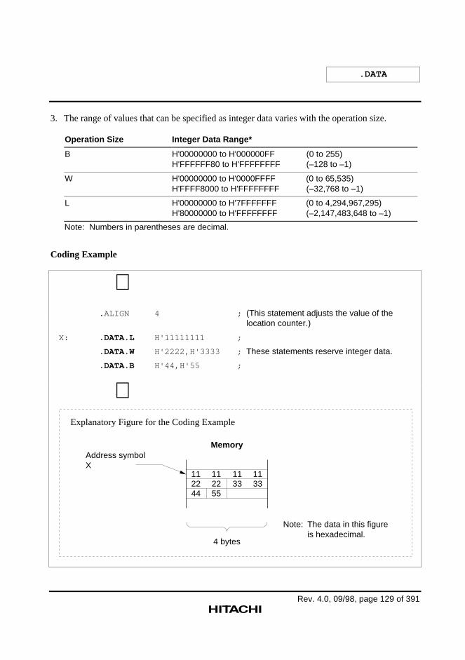
.DATA
Rev. 4.0, 09/98, page 129 of 391
3. The range of values that can be specified as integer data varies with the operation size.
Operation Size Integer Data Range*
B H'00000000 to H'000000FF (0 to 255)H'FFFFFF80 to H'FFFFFFFF (–128 to –1)
W H'00000000 to H'0000FFFF (0 to 65,535)H'FFFF8000 to H'FFFFFFFF (–32,768 to –1)
L H'00000000 to H'7FFFFFFF (0 to 4,294,967,295)H'80000000 to H'FFFFFFFF (–2,147,483,648 to –1)
Note: Numbers in parentheses are decimal.
Coding Example
∼ .ALIGN 4 ; (This statement adjusts the value of the
location counter.)
X: .DATA.L H'11111111 ;
.DATA.W H'2222,H'3333 ; These statements reserve integer data.
.DATA.B H'44,H'55 ;
∼
Memory
4 bytes
112244
112255
1133
1133
Note:
Address symbolX
The data in this figure is hexadecimal.
Explanatory Figure for the Coding Example
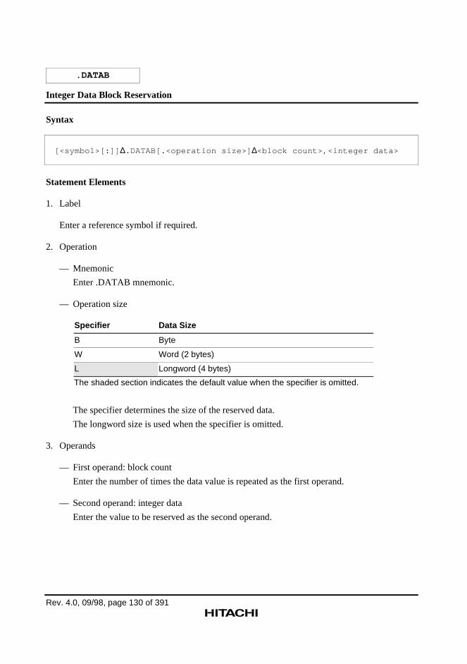
Rev. 4.0, 09/98, page 130 of 391
.DATAB
Integer Data Block Reservation
Syntax
[<symbol>[:]] ∆.DATAB[.<operation size>] ∆<block count>,<integer data>
Statement Elements
1. Label
Enter a reference symbol if required.
2. Operation
— Mnemonic
Enter .DATAB mnemonic.
— Operation size
Specifier Data Size
B Byte
W Word (2 bytes)
L Longword (4 bytes)
The shaded section indicates the default value when the specifier is omitted.
The specifier determines the size of the reserved data.
The longword size is used when the specifier is omitted.
3. Operands
— First operand: block count
Enter the number of times the data value is repeated as the first operand.
— Second operand: integer data
Enter the value to be reserved as the second operand.
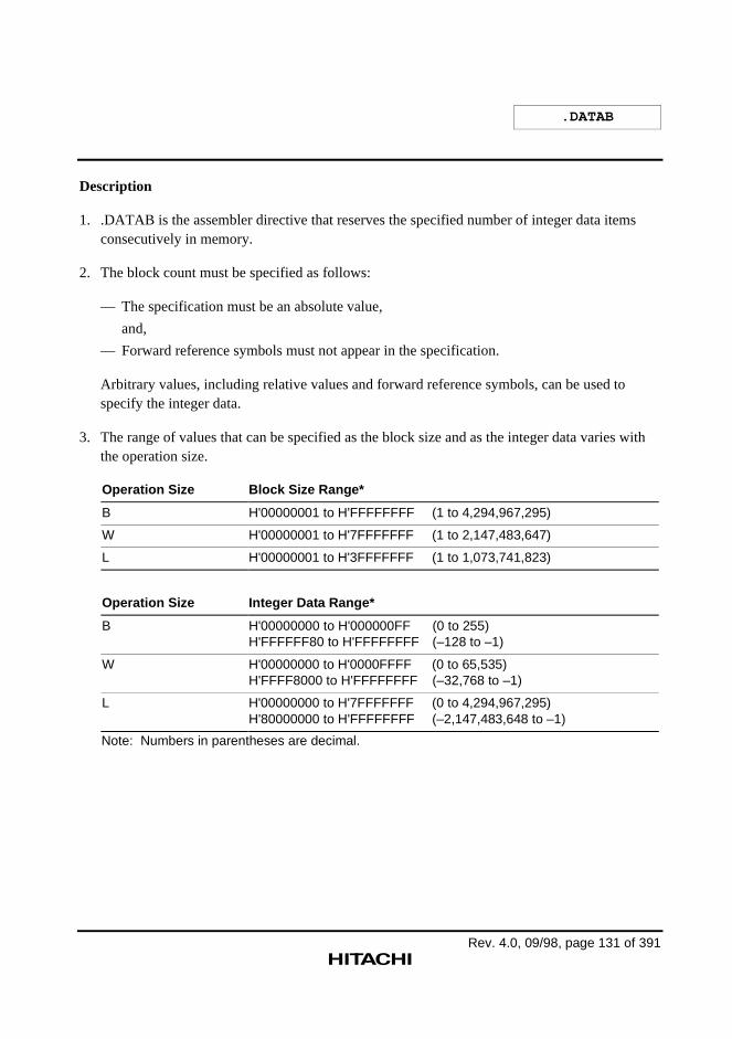
.DATAB
Rev. 4.0, 09/98, page 131 of 391
Description
1. .DATAB is the assembler directive that reserves the specified number of integer data itemsconsecutively in memory.
2. The block count must be specified as follows:
— The specification must be an absolute value,
and,
— Forward reference symbols must not appear in the specification.
Arbitrary values, including relative values and forward reference symbols, can be used tospecify the integer data.
3. The range of values that can be specified as the block size and as the integer data varies withthe operation size.
Operation Size Block Size Range*
B H'00000001 to H'FFFFFFFF (1 to 4,294,967,295)
W H'00000001 to H'7FFFFFFF (1 to 2,147,483,647)
L H'00000001 to H'3FFFFFFF (1 to 1,073,741,823)
Operation Size Integer Data Range*
B H'00000000 to H'000000FF (0 to 255)H'FFFFFF80 to H'FFFFFFFF (–128 to –1)
W H'00000000 to H'0000FFFF (0 to 65,535)H'FFFF8000 to H'FFFFFFFF (–32,768 to –1)
L H'00000000 to H'7FFFFFFF (0 to 4,294,967,295)H'80000000 to H'FFFFFFFF (–2,147,483,648 to –1)
Note: Numbers in parentheses are decimal.
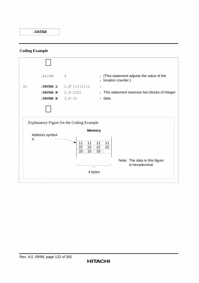
.DATAB
Rev. 4.0, 09/98, page 132 of 391
Coding Example
∼ .ALIGN 4 ; (This statement adjusts the value of the
; location counter.)
X: .DATAB.L 1,H'11111111 ;
.DATAB.W 2,H'2222 ; This statement reserves two blocks of integer
.DATAB.B 3,H'33 ; data.
∼
Memory
4 bytes
112233
112233
112233
1122
Address symbolX
Note: The data in this figure is hexadecimal.
Explanatory Figure for the Coding Example
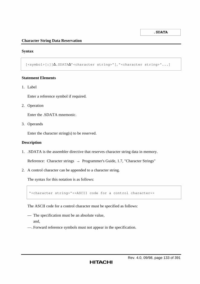
Rev. 4.0, 09/98, page 133 of 391
.SDATA
Character String Data Reservation
Syntax
[<symbol>[:]] ∆.SDATA∆"<character string>"[,"<character string>"...]
Statement Elements
1. Label
Enter a reference symbol if required.
2. Operation
Enter the .SDATA mnemonic.
3. Operands
Enter the character string(s) to be reserved.
Description
1. .SDATA is the assembler directive that reserves character string data in memory.
Reference: Character strings → Programmer's Guide, 1.7, "Character Strings"
2. A control character can be appended to a character string.
The syntax for this notation is as follows:
"<character string>"<<ASCII code for a control character>>
The ASCII code for a control character must be specified as follows:
— The specification must be an absolute value,
and,
—. Forward reference symbols must not appear in the specification.
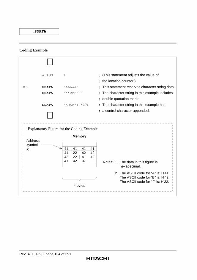
.SDATA
Rev. 4.0, 09/98, page 134 of 391
Coding Example
∼ .ALIGN 4 ; (This statement adjusts the value of
; the location counter.)
X: .SDATA "AAAAA" ; This statement reserves character string data.
.SDATA """BBB""" ; The character string in this example includes
; double quotation marks.
.SDATA "ABAB"<H'07> ; The character string in this example has
; a control character appended.
∼
Memory
4 bytes
41414241
41222242
41424107
414242
Notes:
Address symbolX
The data in this figure is hexadecimal.
The ASCII code for “A” is: H'41.The ASCII code for “B” is: H'42.The ASCII code for “"” is: H'22.
2.
1.
Explanatory Figure for the Coding Example
Rev. 4.0, 09/98, page 135 of 391
.SDATAB
Character String Data Blocks Reservation
Syntax
[<symbol>[:]] ∆.SDATAB∆<block count>,"<character string>"
Statement Elements
1. Label
Enter a reference symbol if required.
2. Operation
Enter the .SDATAB mnemonic.
3. Operands
— First operand: <block count>
Enter the number of character strings as the first operand.
— Second operand: <character string>
Enter the character string to be reserved as the second operand.
Description
1. .SDATAB is the assembler directive that reserves the specified number of character stringsconsecutively in memory.
Reference: Character strings → Programmer's Guide, 1.7, "Character Strings"
2. The <block count> must be specified as follows:
— The specification must be an absolute value,
and,
— Forward reference symbols must not appear in the specification.
A value of 1 or larger must be specified as the block count.
The maximum value of the block count depends on the length of the character string data.
.SDATAB
Rev. 4.0, 09/98, page 136 of 391
(The length of the character string data multiplied by the block count must be less than orequal to H'FFFFFFFF (4,294,967,295) bytes.)
3. A control character can be appended to a character string.
The syntax for this notation is as follows:
"<character string>"<<ASCII code for a control character>>
The ASCII code for a control character must be specified as follows:
— The specification must be an absolute value,
and,
— Forward reference symbols must not appear in the specification.
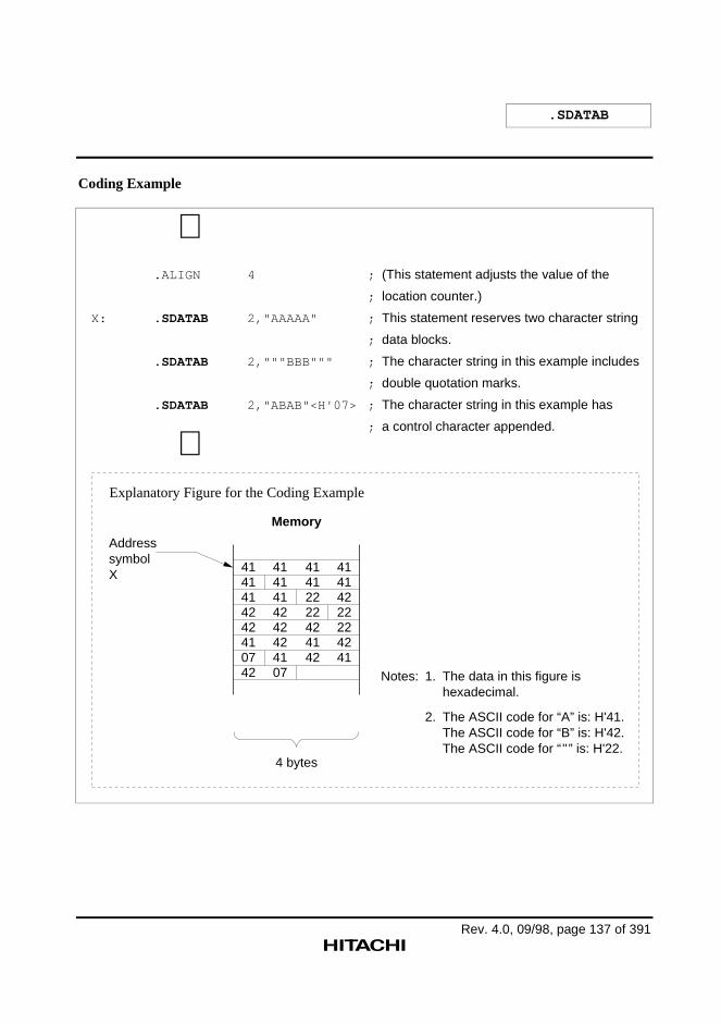
.SDATAB
Rev. 4.0, 09/98, page 137 of 391
Coding Example
∼ .ALIGN 4 ; (This statement adjusts the value of the
; location counter.)
X: .SDATAB 2,"AAAAA" ; This statement reserves two character string
; data blocks.
.SDATAB 2,"""BBB""" ; The character string in this example includes
; double quotation marks.
.SDATAB 2,"ABAB"<H'07> ; The character string in this example has
; a control character appended.
∼
Memory
4 bytes
4141414242410742
4141414242424107
41412222424142
41414222224241
Notes: The data in this figure is hexadecimal.
1.
The ASCII code for “A” is: H'41.The ASCII code for “B” is: H'42.The ASCII code for “"” is: H'22.
2.
Address symbolX
Explanatory Figure for the Coding Example
Rev. 4.0, 09/98, page 138 of 391
.SDATAC
Character String Data Reservation (With Length)
Syntax
[<symbol>[:]] ∆.SDATAC∆"<character string>"[,"<character string>"...]
Statement Elements
1. Label
Enter a reference symbol if required.
2. Operation
Enter the .SDATAC mnemonic.
3. Operands
Enter the character string(s) to be reserved.
Description
1. .SDATAC is the assembler directive that reserves character string data (with length) inmemory.
A character string with length is a character string with an inserted leading byte that indicatesthe length of the string.
The length indicates the size of the character string (not including the length) in bytes.
Reference: Character strings → Programmer's Guide, 1.7, "Character Strings"
2. A control character can be appended to a character string.
The syntax for this notation is as follows:
"<character string>"<<ASCII code for a control character>>
The ASCII code for a control character must be specified as follows:
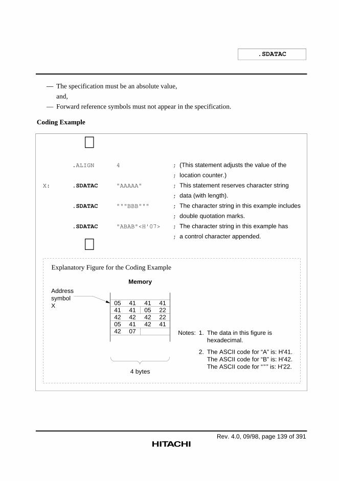
.SDATAC
Rev. 4.0, 09/98, page 139 of 391
— The specification must be an absolute value,
and,
— Forward reference symbols must not appear in the specification.
Coding Example
∼ .ALIGN 4 ; (This statement adjusts the value of the
; location counter.)
X: .SDATAC "AAAAA" ; This statement reserves character string
; data (with length).
.SDATAC """BBB""" ; The character string in this example includes
; double quotation marks.
.SDATAC "ABAB"<H'07> ; The character string in this example has
; a control character appended.
∼
Memory
4 bytes
0541420542
4141424107
41054242
41222241
Notes: The data in this figure is hexadecimal.
1.
The ASCII code for “A” is: H'41.The ASCII code for “B” is: H'42.The ASCII code for “"” is: H'22.
2.
Address symbolX
Explanatory Figure for the Coding Example
Rev. 4.0, 09/98, page 140 of 391
.SDATAZ
Character String Data Reservation (With Zero Terminator)
Syntax
[<symbol>[:]] ∆.SDATAZ∆"<character string>"[,"<character string>"...]
Statement Elements
1. Label
Enter a reference symbol if required.
2. Operation
Enter the .SDATAZ mnemonic.
3. Operands
Enter the character string(s) to be reserved.
Description
1. .SDATAZ is the assembler directive that reserves character string data (with zero terminator)in memory.
A character string with zero terminator is a character string with an appended trailing byte(with the value H'00) that indicates the end of the string.
Reference: Character strings → Programmer's Guide, 1.7, "Character Strings"
2. A control character can be appended to a character string.
The syntax for this notation is as follows:
"<character string>"<<ASCII code for a control character>>
The ASCII code for a control character must be specified as follows:
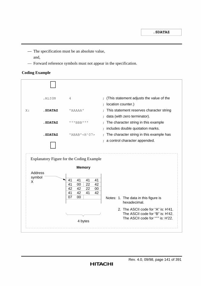
.SDATAZ
Rev. 4.0, 09/98, page 141 of 391
— The specification must be an absolute value,
and,
— Forward reference symbols must not appear in the specification.
Coding Example
∼ .ALIGN 4 ; (This statement adjusts the value of the
; location counter.)
X: .SDATAZ "AAAAA" ; This statement reserves character string
; data (with zero terminator).
.SDATAZ """BBB""" ; The character string in this example
; includes double quotation marks.
.SDATAZ "ABAB"<H'07> ; The character string in this example has
; a control character appended.
∼
Memory
4 bytes
4141424107
4100424200
41222241
41420042
Notes: The data in this figure is hexadecimal.
1.
The ASCII code for “A” is: H'41.The ASCII code for “B” is: H'42.The ASCII code for “"” is: H'22.
2.
Address symbolX
Explanatory Figure for the Coding Example
Rev. 4.0, 09/98, page 142 of 391
.FDATA
Floating-Point Data Reservation
Syntax
[<symbol>[:]] ∆.FDATA[.operation size] ∆<floating-point data>[,<floating-point data>...]
Statement Elements
1. Label
Enter a reference symbol if required.
2. Operation
— Mnemonic
Enter .FDATA mnemonic.
— Operation size
Specifier Data Size
S Single precision (4 bytes)
D Double precision (8 bytes)
The shaded section indicates the default value when the specifier is omitted.
The specifier determines the size of the reserved data.
Single precision is used when the specifier is omitted.
3. Operands
Enter the values to be reserved as data.
Description
1. .FDATA is the assembler directive that reserves floating-point data in memory.
Reference: Floating-point data→ Programmer's Guide, 1.4.3, "Floating-Point Constants"
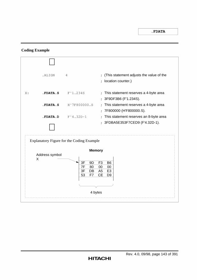
.FDATA
Rev. 4.0, 09/98, page 143 of 391
Coding Example
∼ .ALIGN 4 ; (This statement adjusts the value of the
; location counter.)
X: .FDATA.S F'1.234S ; This statement reserves a 4-byte area
; 3F9DF3B6 (F'1.234S).
.FDATA.S H'7F800000.S ; This statement reserves a 4-byte area
; 7F800000 (H'F800000.S).
.FDATA.D F'4.32D-1 ; This statement reserves an 8-byte area
; 3FDBA5E353F7CED9 (F'4.32D-1).
∼
Memory
4 bytes
3F7F3F53
9D80DBF7
F300A5CE
B600E3D9
Address symbolX
Explanatory Figure for the Coding Example
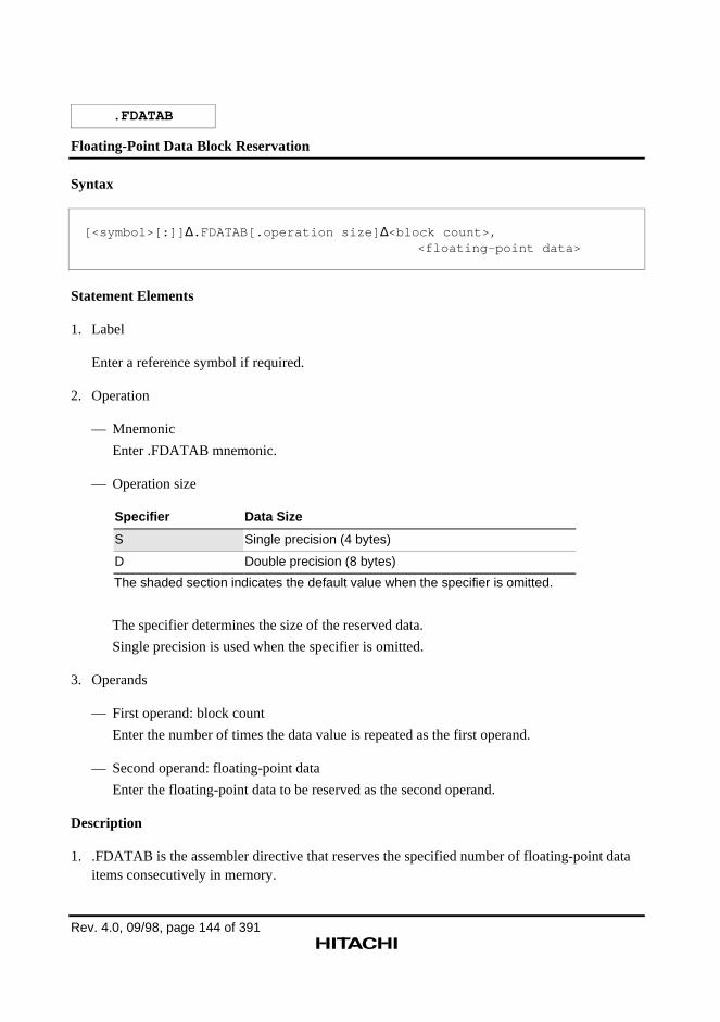
Rev. 4.0, 09/98, page 144 of 391
.FDATAB
Floating-Point Data Block Reservation
Syntax
[<symbol>[:]] ∆.FDATAB[.operation size] ∆<block count>,<floating-point data>
Statement Elements
1. Label
Enter a reference symbol if required.
2. Operation
— Mnemonic
Enter .FDATAB mnemonic.
— Operation size
Specifier Data Size
S Single precision (4 bytes)
D Double precision (8 bytes)
The shaded section indicates the default value when the specifier is omitted.
The specifier determines the size of the reserved data.
Single precision is used when the specifier is omitted.
3. Operands
— First operand: block count
Enter the number of times the data value is repeated as the first operand.
— Second operand: floating-point data
Enter the floating-point data to be reserved as the second operand.
Description
1. .FDATAB is the assembler directive that reserves the specified number of floating-point dataitems consecutively in memory.
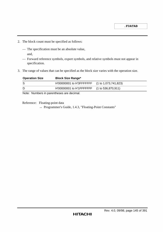
.FDATAB
Rev. 4.0, 09/98, page 145 of 391
2. The block count must be specified as follows:
— The specification must be an absolute value,
and,
— Forward reference symbols, export symbols, and relative symbols must not appear inspecification.
3. The range of values that can be specified as the block size varies with the operation size.
Operation Size Block Size Range*
S H'00000001 to H'3FFFFFFF (1 to 1,073,741,823)
D H'00000001 to H'1FFFFFFF (1 to 536,870,911)
Note: Numbers in parentheses are decimal.
Reference: Floating-point data→ Programmer's Guide, 1.4.3, "Floating-Point Constants"
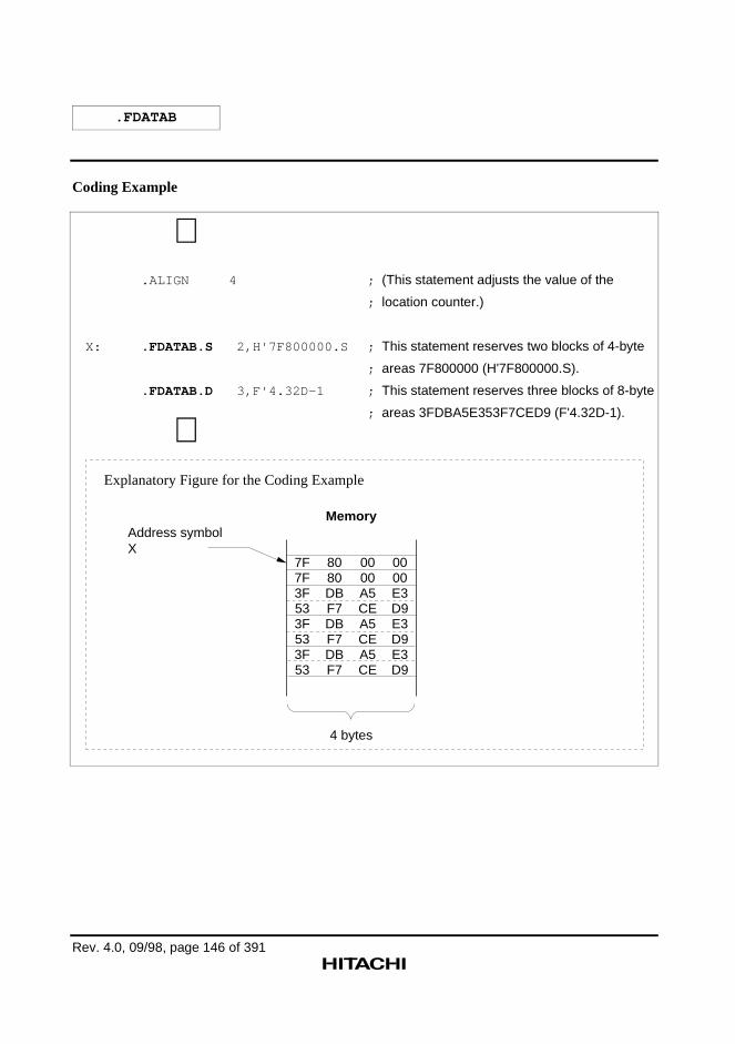
.FDATAB
Rev. 4.0, 09/98, page 146 of 391
Coding Example
∼ .ALIGN 4 ; (This statement adjusts the value of the
; location counter.)
X: .FDATAB.S 2,H'7F800000.S ; This statement reserves two blocks of 4-byte
; areas 7F800000 (H'7F800000.S).
.FDATAB.D 3,F'4.32D-1 ; This statement reserves three blocks of 8-byte
; areas 3FDBA5E353F7CED9 (F'4.32D-1).
∼
Memory
4 bytes
7F7F3F533F533F53
8080DBF7DBF7DBF7
0000A5CEA5CEA5CE
0000E3D9E3D9E3D9
Address symbolX
Explanatory Figure for the Coding Example
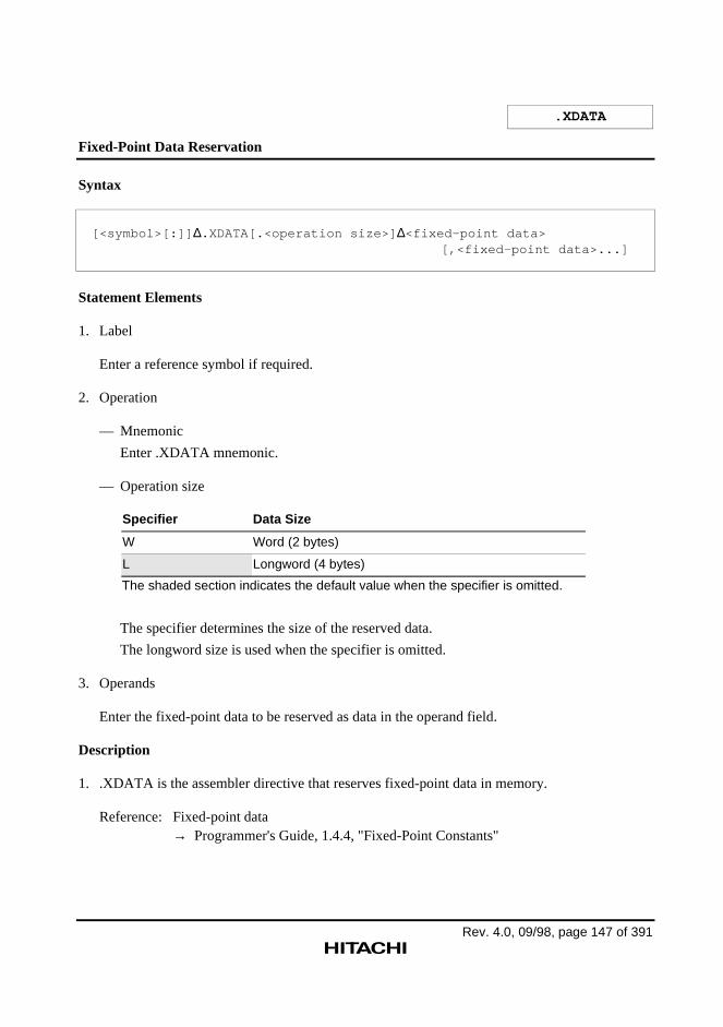
Rev. 4.0, 09/98, page 147 of 391
.XDATA
Fixed-Point Data Reservation
Syntax
[<symbol>[:]] ∆.XDATA[.<operation size>] ∆<fixed-point data>[,<fixed-point data>...]
Statement Elements
1. Label
Enter a reference symbol if required.
2. Operation
— Mnemonic
Enter .XDATA mnemonic.
— Operation size
Specifier Data Size
W Word (2 bytes)
L Longword (4 bytes)
The shaded section indicates the default value when the specifier is omitted.
The specifier determines the size of the reserved data.
The longword size is used when the specifier is omitted.
3. Operands
Enter the fixed-point data to be reserved as data in the operand field.
Description
1. .XDATA is the assembler directive that reserves fixed-point data in memory.
Reference: Fixed-point data→ Programmer's Guide, 1.4.4, "Fixed-Point Constants"
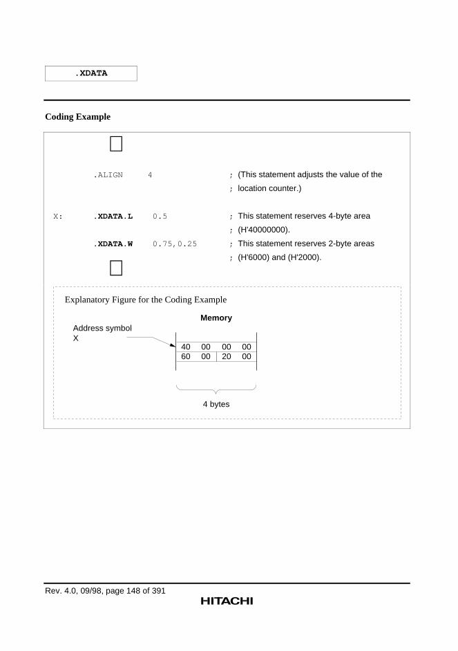
.XDATA
Rev. 4.0, 09/98, page 148 of 391
Coding Example
∼ .ALIGN 4 ; (This statement adjusts the value of the
; location counter.)
X: . XDATA.L 0.5 ; This statement reserves 4-byte area
; (H'40000000).
. XDATA.W 0.75,0.25 ; This statement reserves 2-byte areas
; (H'6000) and (H'2000).
∼
Memory
4 bytes
4060
0000
0020
0000
Address symbolX
Explanatory Figure for the Coding Example
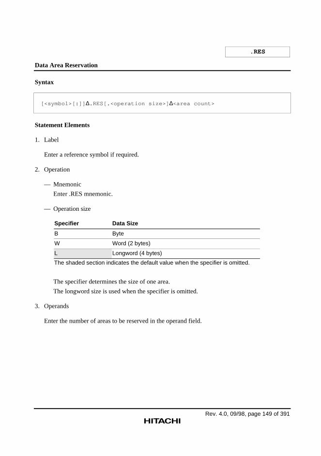
Rev. 4.0, 09/98, page 149 of 391
.RES
Data Area Reservation
Syntax
[<symbol>[:]] ∆.RES[.<operation size>] ∆<area count>
Statement Elements
1. Label
Enter a reference symbol if required.
2. Operation
— Mnemonic
Enter .RES mnemonic.
— Operation size
Specifier Data Size
B Byte
W Word (2 bytes)
L Longword (4 bytes)
The shaded section indicates the default value when the specifier is omitted.
The specifier determines the size of one area.
The longword size is used when the specifier is omitted.
3. Operands
Enter the number of areas to be reserved in the operand field.
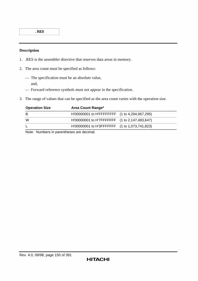
.RES
Rev. 4.0, 09/98, page 150 of 391
Description
1. .RES is the assembler directive that reserves data areas in memory.
2. The area count must be specified as follows:
— The specification must be an absolute value,
and,
— Forward reference symbols must not appear in the specification.
3. The range of values that can be specified as the area count varies with the operation size.
Operation Size Area Count Range*
B H'00000001 to H'FFFFFFFF (1 to 4,294,967,295)
W H'00000001 to H'7FFFFFFF (1 to 2,147,483,647)
L H'00000001 to H'3FFFFFFF (1 to 1,073,741,823)
Note: Numbers in parentheses are decimal.
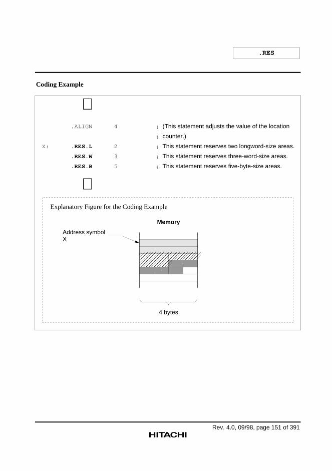
.RES
Rev. 4.0, 09/98, page 151 of 391
Coding Example
∼ .ALIGN 4 ; (This statement adjusts the value of the location
; counter.)
X: .RES.L 2 ; This statement reserves two longword-size areas.
.RES.W 3 ; This statement reserves three-word-size areas.
.RES.B 5 ; This statement reserves five-byte-size areas.
∼
Memory
4 bytes
��������������������������������������������������������������������������������������������
������������������������������������������������
Address symbolX
Explanatory Figure for the Coding Example
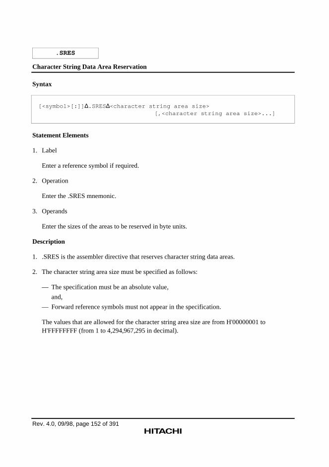
Rev. 4.0, 09/98, page 152 of 391
.SRES
Character String Data Area Reservation
Syntax
[<symbol>[:]] ∆.SRES∆<character string area size>[,<character string area size>...]
Statement Elements
1. Label
Enter a reference symbol if required.
2. Operation
Enter the .SRES mnemonic.
3. Operands
Enter the sizes of the areas to be reserved in byte units.
Description
1. .SRES is the assembler directive that reserves character string data areas.
2. The character string area size must be specified as follows:
— The specification must be an absolute value,
and,
— Forward reference symbols must not appear in the specification.
The values that are allowed for the character string area size are from H'00000001 toH'FFFFFFFF (from 1 to 4,294,967,295 in decimal).
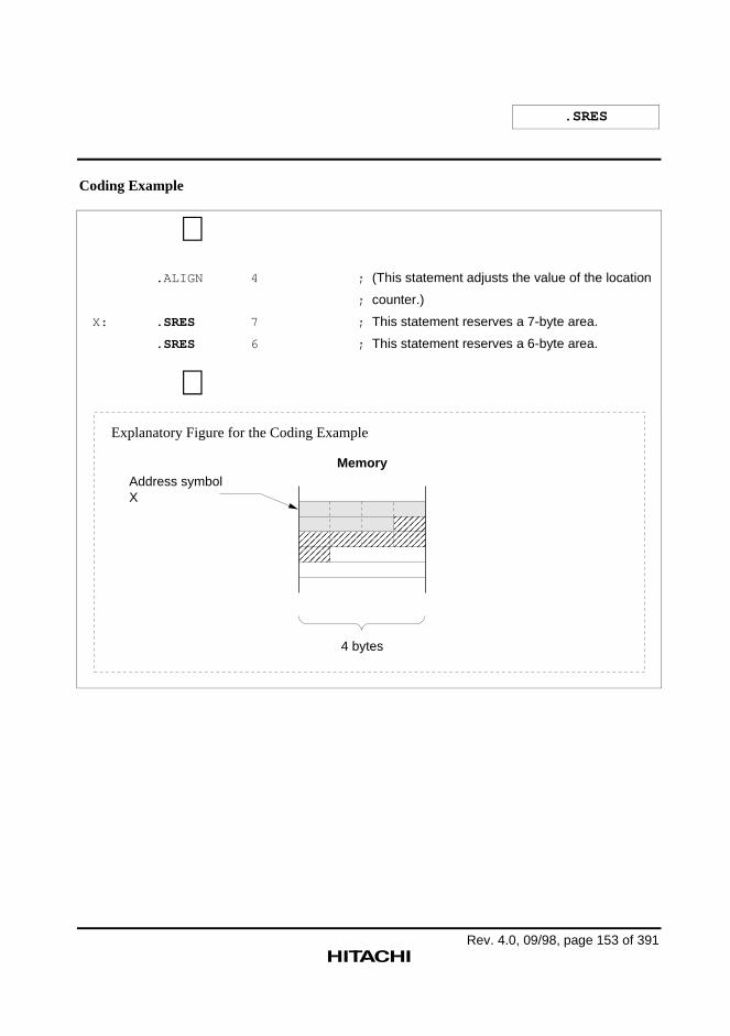
.SRES
Rev. 4.0, 09/98, page 153 of 391
Coding Example
∼ .ALIGN 4 ; (This statement adjusts the value of the location
; counter.)
X: .SRES 7 ; This statement reserves a 7-byte area.
.SRES 6 ; This statement reserves a 6-byte area.
∼
���������������������������������������������������������������������������������������������������������������������������������������������������������������������������������������������������������������
Memory
4 bytes
Address symbolX
Explanatory Figure for the Coding Example
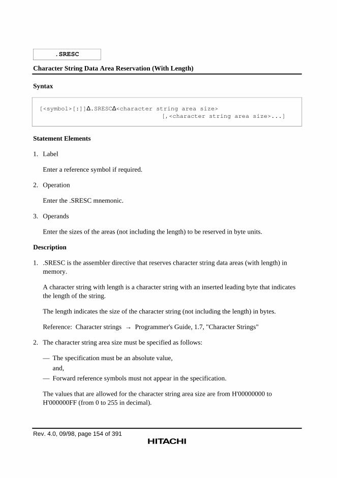
Rev. 4.0, 09/98, page 154 of 391
.SRESC
Character String Data Area Reservation (With Length)
Syntax
[<symbol>[:]] ∆.SRESC∆<character string area size>[,<character string area size>...]
Statement Elements
1. Label
Enter a reference symbol if required.
2. Operation
Enter the .SRESC mnemonic.
3. Operands
Enter the sizes of the areas (not including the length) to be reserved in byte units.
Description
1. .SRESC is the assembler directive that reserves character string data areas (with length) inmemory.
A character string with length is a character string with an inserted leading byte that indicatesthe length of the string.
The length indicates the size of the character string (not including the length) in bytes.
Reference: Character strings → Programmer's Guide, 1.7, "Character Strings"
2. The character string area size must be specified as follows:
— The specification must be an absolute value,
and,
— Forward reference symbols must not appear in the specification.
The values that are allowed for the character string area size are from H'00000000 toH'000000FF (from 0 to 255 in decimal).
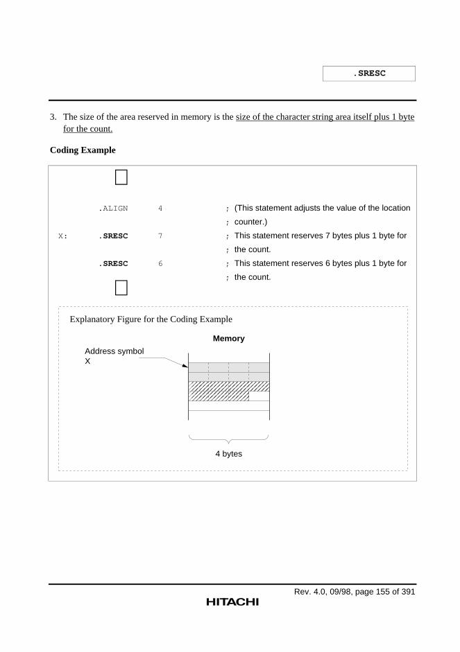
.SRESC
Rev. 4.0, 09/98, page 155 of 391
3. The size of the area reserved in memory is the size of the character string area itself plus 1 bytefor the count.
Coding Example
∼ .ALIGN 4 ; (This statement adjusts the value of the location
; counter.)
X: .SRESC 7 ; This statement reserves 7 bytes plus 1 byte for
; the count.
.SRESC 6 ; This statement reserves 6 bytes plus 1 byte for
; the count.
∼
������������������������������������������������������������������������������������������������������������������������������������
Memory
4 bytes
Address symbolX
Explanatory Figure for the Coding Example
Rev. 4.0, 09/98, page 156 of 391
.SRESZ
Character String Data Area Reservation (With Zero Terminator)
Syntax
[<symbol>[:]] ∆.SRESZ∆<character string area size>[,<character string area size>...]
Statement Elements
1. Label
Enter a reference symbol if required.
2. Operation
Enter the .SRESZ mnemonic.
3. Operands
Enter the sizes of the areas (not including the terminating zero) to be reserved in byte units.
Description
1. .SRESZ is the assembler directive that allocates character string data areas (with zerotermination).
A character string with length is a character string with an appended trailing byte (with thevalue H'00) that indicates the end of the string.
Reference: Character strings → Programmer's Guide, 1.7, "Character Strings"
2. The character string area size must be specified as follows:
— The specification must be an absolute value,
and,
— Forward reference symbols must not appear in the specification.
The values that are allowed for the character string area size are from H'00000000 toH'000000FF (from 0 to 255 in decimal).
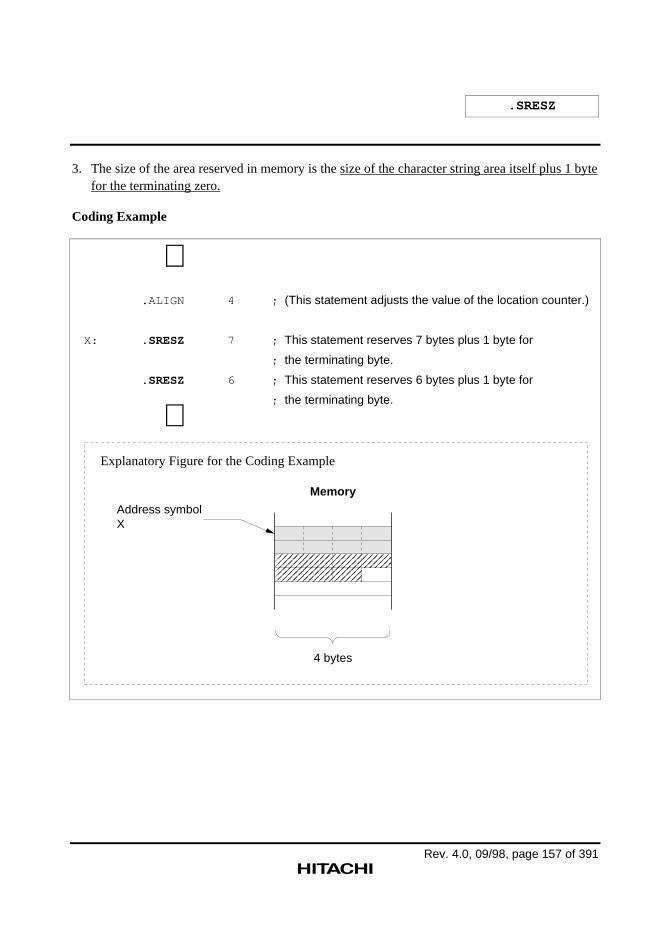
.SRESZ
Rev. 4.0, 09/98, page 157 of 391
3. The size of the area reserved in memory is the size of the character string area itself plus 1 bytefor the terminating zero.
Coding Example
∼ .ALIGN 4 ; (This statement adjusts the value of the location counter.)
X: .SRESZ 7 ; This statement reserves 7 bytes plus 1 byte for
; the terminating byte.
.SRESZ 6 ; This statement reserves 6 bytes plus 1 byte for
; the terminating byte.
∼
������������������������������������������������������������������������������������������������������������������������������������������
Memory
4 bytes
Address symbolX
Explanatory Figure for the Coding Example
Rev. 4.0, 09/98, page 158 of 391
.FRES
Floating-Point Data Area Reservation
Syntax
[<symbol>[:]] ∆.FRES[S] ∆<area count>
Statement Elements
1. Label
Enter a reference symbol if required.
2. Operation
— Mnemonic
Enter .FRES mnemonic.
— Operation size
Specifier Data Size
S Single precision (4 bytes)
D Double precision (8 bytes)
The shaded section indicates the default value when the specifier is omitted.
The specifier determines the size of one area.
Single precision is used when the specifier is omitted.
3. Operands
Enter the number of areas (the number of single-precision data items).
Description
1. .FRES is the assembler directive that reserves floating-point data areas in memory.
2. The area count must be specified as follows:
— The specification must be an absolute value,
and,
— Forward reference symbols, import symbols, and relative symbols must not appear in thespecification.
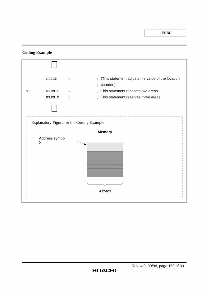
.FRES
Rev. 4.0, 09/98, page 159 of 391
Coding Example
∼ .ALIGN 4 ; (This statement adjusts the value of the location
; counter.)
X: .FRES.S 2 ; This statement reserves two areas.
.FRES.D 3 ; This statement reserves three areas.
∼
Memory
4 bytes
Address symbolX
Explanatory Figure for the Coding Example
Rev. 4.0, 09/98, page 160 of 391
5.2.5 Export and Import Assembler Directives
This assembler provides the following assembler directives concerned with export and import.
.EXPORT
Declares export symbols.
This declaration allows symbols defined in the current file to be referenced in other files.
.IMPORT
Declares import symbols.
This declaration allows symbols defined in other files to be referenced in the current file.
.GLOBAL
Declares export and import symbols.
This declaration allows symbols defined in the current file to be referenced in other files, andallows symbols defined in other files to be referenced in the current file.
Rev. 4.0, 09/98, page 161 of 391
.EXPORT
Export Symbols Declaration
Syntax
∆.EXPORT∆<symbol>[,<symbol>...]
Statement Elements
1. Label
The label field is not used.
2. Operation
Enter the .EXPORT mnemonic.
3. Operands
Enter the symbols to be declared as export symbols.
Description
1. .EXPORT is the assembler directive that declares export symbols.
An export symbol declaration is required to reference symbols defined in the current file fromother files.
2. The following can be declared to be export symbols.
— Constant symbols (other than those defined with the .ASSIGN directive)
— Absolute address symbols (other than address symbols in a dummy section)
— Relative address symbols
3. To reference a symbol as an import symbol, it is necessary to declare it to be an export symbol,and also to declare it to be an import symbol.
Import symbols are declared in the file in which they are referenced using either the .IMPORTor the .GLOBAL directive.
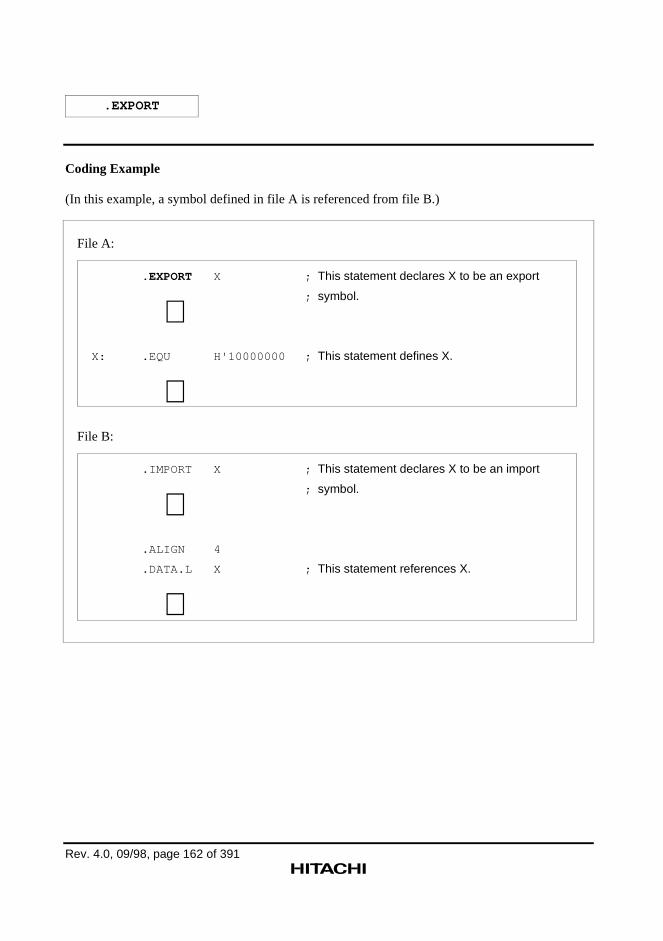
.EXPORT
Rev. 4.0, 09/98, page 162 of 391
Coding Example
(In this example, a symbol defined in file A is referenced from file B.)
File A:
.EXPORT X ; This statement declares X to be an export
; symbol.
∼ X: .EQU H'10000000 ; This statement defines X.
∼File B:
.IMPORT X ; This statement declares X to be an import
; symbol.
∼ .ALIGN 4
.DATA.L X ; This statement references X.
∼
Rev. 4.0, 09/98, page 163 of 391
.IMPORT
Import Symbols Declaration
Syntax
∆.IMPORT∆<symbol>[,<symbol>...]
Statement Elements
1. Label
The label field is not used.
2. Operation
Enter the .IMPORT mnemonic.
3. Operands
Enter the symbols to be declared as import symbols.
Description
1. .IMPORT is the assembler directive that declares import symbols.
An import symbol declaration is required to reference symbols defined in another file.
2. Symbols defined in the current file cannot be declared to be import symbols.
3. To reference a symbol as an import symbol, it is necessary to declare it to be an export symbol,and also to declare it to be an import symbol.
Export symbols are declared in the file in which they are defined using either the .EXPORT orthe .GLOBAL directive.
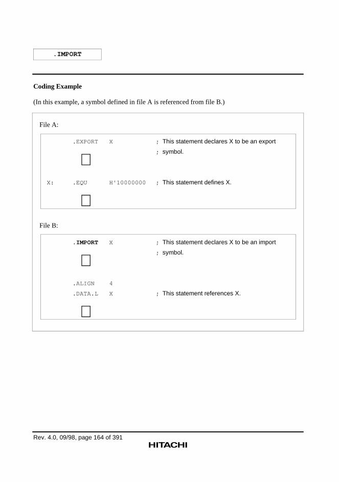
.IMPORT
Rev. 4.0, 09/98, page 164 of 391
Coding Example
(In this example, a symbol defined in file A is referenced from file B.)
File A:
.EXPORT X ; This statement declares X to be an export
; symbol.
∼ X: .EQU H'10000000 ; This statement defines X.
∼File B:
.IMPORT X ; This statement declares X to be an import
; symbol.
∼ .ALIGN 4
.DATA.L X ; This statement references X.
∼
Rev. 4.0, 09/98, page 165 of 391
.GLOBAL
Export and Import Symbols Declaration
Syntax
∆.GLOBAL∆<symbol>[,<symbol>...]
Statement Elements
1. Label
The label field is not used.
2. Operation
Enter the .GLOBAL mnemonic.
3. Operands
Enter the symbols to be declared as export symbols or as import symbols.
Description
1. .GLOBAL is the assembler directive that declares symbols to be either export symbols orimport symbols.
An export symbol declaration is required to reference symbols defined in the current file fromother files. An import symbol declaration is required to reference symbols defined in anotherfile.
2. A symbol defined within the current file is declared to be an export symbol by a .GLOBALdeclaration.
A symbol that is not defined within the current file is declared to be an import symbol by a.GLOBAL declaration.
3. The following can be declared to be export symbols.
— Constant symbols (other than those defined with the .ASSIGN assembler directive)
— Absolute address symbols (other than address symbols in a dummy section)
— Relative address symbols
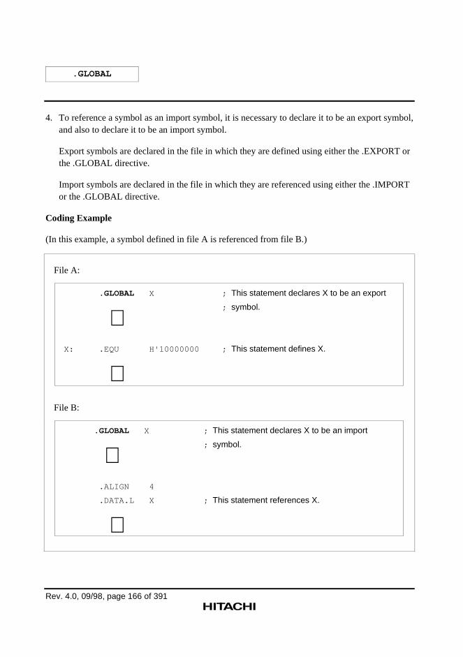
.GLOBAL
Rev. 4.0, 09/98, page 166 of 391
4. To reference a symbol as an import symbol, it is necessary to declare it to be an export symbol,and also to declare it to be an import symbol.
Export symbols are declared in the file in which they are defined using either the .EXPORT orthe .GLOBAL directive.
Import symbols are declared in the file in which they are referenced using either the .IMPORTor the .GLOBAL directive.
Coding Example
(In this example, a symbol defined in file A is referenced from file B.)
File A:
.GLOBAL X ; This statement declares X to be an export
; symbol.
∼ X: .EQU H'10000000 ; This statement defines X.
∼File B:
.GLOBAL X ; This statement declares X to be an import
; symbol.
∼ .ALIGN 4
.DATA.L X ; This statement references X.
∼
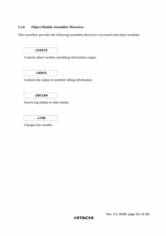
Rev. 4.0, 09/98, page 167 of 391
5.2.6 Object Module Assembler Directives
This assembler provides the following assembler directives concerned with object modules.
.OUTPUT
Controls object module and debug information output.
.DEBUG
Controls the output of symbolic debug information.
.ENDIAN
Selects big endian or little endian.
.LINE
Changes line number.
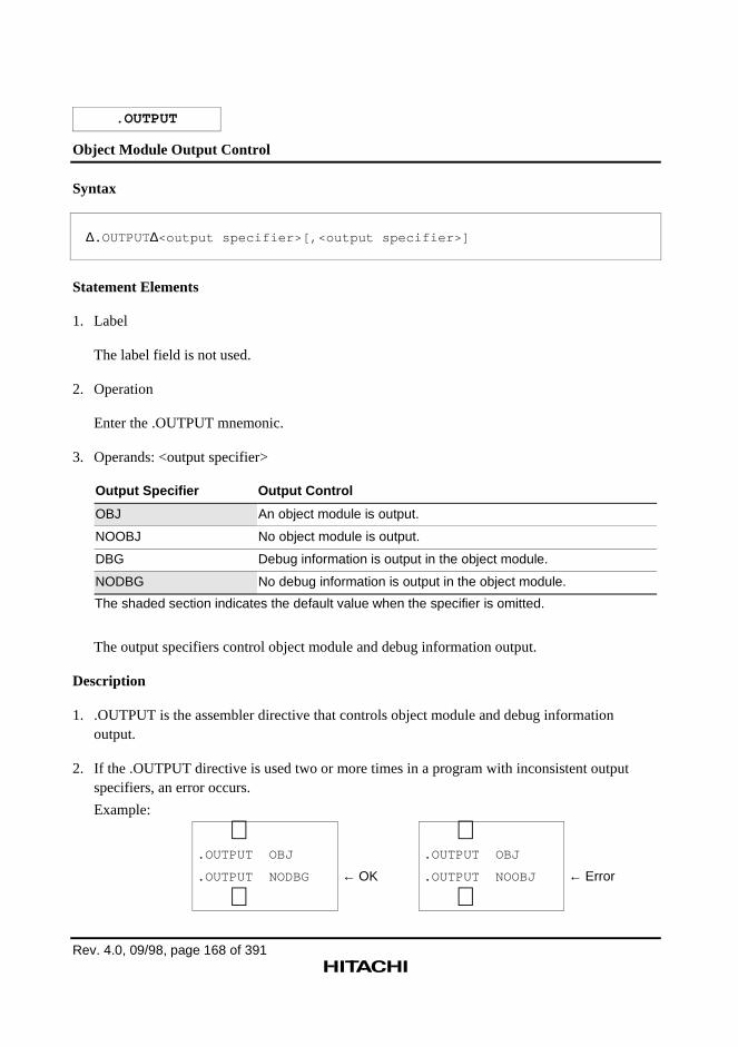
Rev. 4.0, 09/98, page 168 of 391
.OUTPUT
Object Module Output Control
Syntax
∆.OUTPUT∆<output specifier>[,<output specifier>]
Statement Elements
1. Label
The label field is not used.
2. Operation
Enter the .OUTPUT mnemonic.
3. Operands: <output specifier>
Output Specifier Output Control
OBJ An object module is output.
NOOBJ No object module is output.
DBG Debug information is output in the object module.
NODBG No debug information is output in the object module.
The shaded section indicates the default value when the specifier is omitted.
The output specifiers control object module and debug information output.
Description
1. .OUTPUT is the assembler directive that controls object module and debug informationoutput.
2. If the .OUTPUT directive is used two or more times in a program with inconsistent outputspecifiers, an error occurs.
Example:
∼.OUTPUT OBJ
.OUTPUT NODBG
∼← OK
∼.OUTPUT OBJ
.OUTPUT NOOBJ
∼← Error
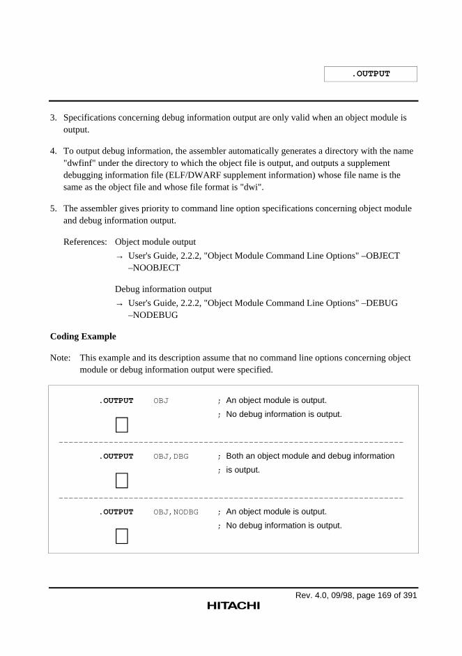
.OUTPUT
Rev. 4.0, 09/98, page 169 of 391
3. Specifications concerning debug information output are only valid when an object module isoutput.
4. To output debug information, the assembler automatically generates a directory with the name"dwfinf" under the directory to which the object file is output, and outputs a supplementdebugging information file (ELF/DWARF supplement information) whose file name is thesame as the object file and whose file format is "dwi".
5. The assembler gives priority to command line option specifications concerning object moduleand debug information output.
References: Object module output
→ User's Guide, 2.2.2, "Object Module Command Line Options" –OBJECT–NOOBJECT
Debug information output
→ User's Guide, 2.2.2, "Object Module Command Line Options" –DEBUG–NODEBUG
Coding Example
Note: This example and its description assume that no command line options concerning objectmodule or debug information output were specified.
.OUTPUT OBJ ; An object module is output.
; No debug information is output.
∼---------------------------------------------------------------------
.OUTPUT OBJ,DBG ; Both an object module and debug information
; is output.
∼---------------------------------------------------------------------
.OUTPUT OBJ,NODBG ; An object module is output.
; No debug information is output.
∼
.OUTPUT
Rev. 4.0, 09/98, page 170 of 391
Supplement:
Debug information is required when debugging a program using the debugger, and is part of theobject module.
Debug information includes information about source statements and information about symbols.
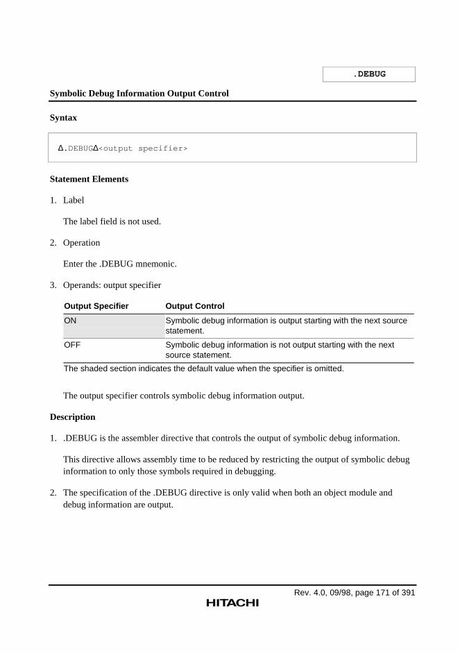
Rev. 4.0, 09/98, page 171 of 391
.DEBUG
Symbolic Debug Information Output Control
Syntax
∆.DEBUG∆<output specifier>
Statement Elements
1. Label
The label field is not used.
2. Operation
Enter the .DEBUG mnemonic.
3. Operands: output specifier
Output Specifier Output Control
ON Symbolic debug information is output starting with the next sourcestatement.
OFF Symbolic debug information is not output starting with the nextsource statement.
The shaded section indicates the default value when the specifier is omitted.
The output specifier controls symbolic debug information output.
Description
1. .DEBUG is the assembler directive that controls the output of symbolic debug information.
This directive allows assembly time to be reduced by restricting the output of symbolic debuginformation to only those symbols required in debugging.
2. The specification of the .DEBUG directive is only valid when both an object module anddebug information are output.
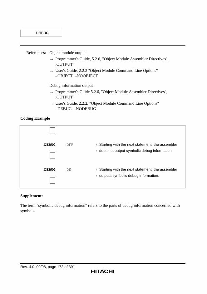
.DEBUG
Rev. 4.0, 09/98, page 172 of 391
References: Object module output
→ Programmer's Guide, 5.2.6, "Object Module Assembler Directives",.OUTPUT
→ User's Guide, 2.2.2 "Object Module Command Line Options"–OBJECT –NOOBJECT
Debug information output
→ Programmer's Guide 5.2.6, "Object Module Assembler Directives",.OUTPUT
→ User's Guide, 2.2.2, "Object Module Command Line Options"–DEBUG –NODEBUG
Coding Example
∼ .DEBUG OFF ; Starting with the next statement, the assembler
; does not output symbolic debug information.
∼ .DEBUG ON ; Starting with the next statement, the assembler
; outputs symbolic debug information.
∼Supplement:
The term "symbolic debug information" refers to the parts of debug information concerned withsymbols.
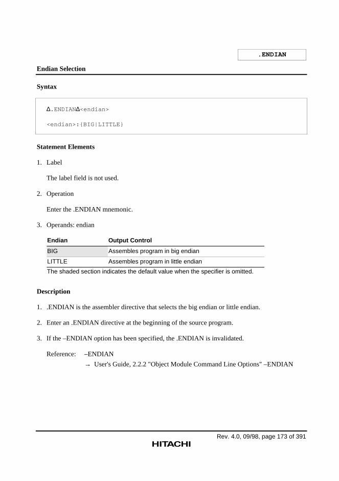
Rev. 4.0, 09/98, page 173 of 391
.ENDIAN
Endian Selection
Syntax
∆.ENDIAN ∆<endian>
<endian>:{BIG|LITTLE}
Statement Elements
1. Label
The label field is not used.
2. Operation
Enter the .ENDIAN mnemonic.
3. Operands: endian
Endian Output Control
BIG Assembles program in big endian
LITTLE Assembles program in little endian
The shaded section indicates the default value when the specifier is omitted.
Description
1. .ENDIAN is the assembler directive that selects the big endian or little endian.
2. Enter an .ENDIAN directive at the beginning of the source program.
3. If the –ENDIAN option has been specified, the .ENDIAN is invalidated.
Reference: –ENDIAN
→ User's Guide, 2.2.2 "Object Module Command Line Options" –ENDIAN
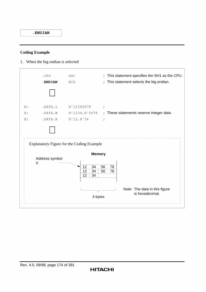
.ENDIAN
Rev. 4.0, 09/98, page 174 of 391
Coding Example
1. When the big endian is selected
.CPU SH1 ; This statement specifies the SH1 as the CPU.
.ENDIAN BIG ; This statement selects the big endian.
∼X: .DATA.L H'12345678 ;
X: .DATA.W H'1234,H'5678 ; These statements reserve integer data.
X: .DATA.B H'12,H'34 ;
∼
Memory
4 bytes
121212
343434
5656
7878
Note:
Address symbolX
The data in this figure is hexadecimal.
Explanatory Figure for the Coding Example
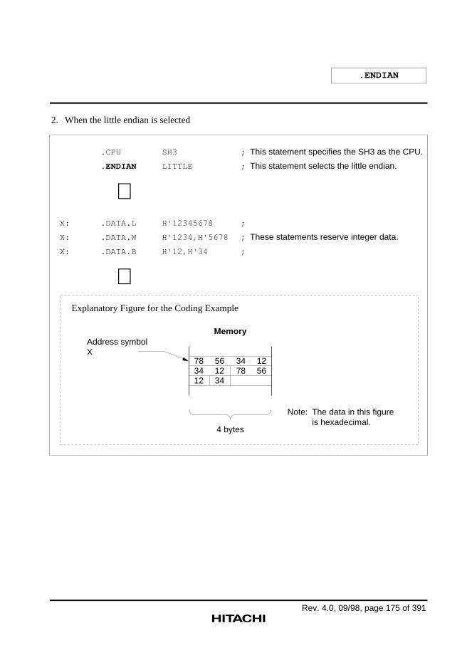
.ENDIAN
Rev. 4.0, 09/98, page 175 of 391
2. When the little endian is selected
.CPU SH3 ; This statement specifies the SH3 as the CPU.
.ENDIAN LITTLE ; This statement selects the little endian.
∼X: .DATA.L H'12345678 ;
X: .DATA.W H'1234,H'5678 ; These statements reserve integer data.
X: .DATA.B H'12,H'34 ;
∼
Memory
4 bytes
783412
561234
3478
1256
Note:
Address symbolX
The data in this figure is hexadecimal.
Explanatory Figure for the Coding Example
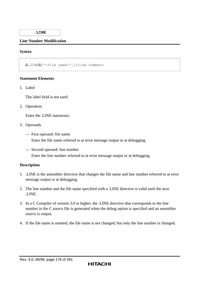
Rev. 4.0, 09/98, page 176 of 391
.LINE
Line Number Modification
Syntax
∆.LINE ∆["<file name>",]<line number>
Statement Elements
1. Label
The label field is not used.
2. Operation
Enter the .LINE mnemonic.
3. Operands
— First operand: file name
Enter the file name referred to at error message output or at debugging.
— Second operand: line number
Enter the line number referred to at error message output or at debugging.
Description
1. .LINE is the assembler directive that changes the file name and line number referred to at errormessage output or at debugging.
2. The line number and the file name specified with a .LINE directive is valid until the next.LINE.
3. In a C Compiler of version 3.0 or higher, the .LINE directive that corresponds to the linenumber in the C source file is generated when the debug option is specified and an assemblersource is output.
4. If the file name is omitted, the file name is not changed, but only the line number is changed.
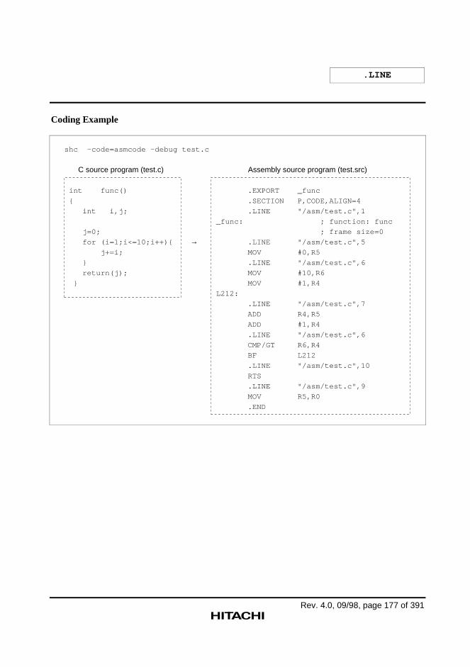
.LINE
Rev. 4.0, 09/98, page 177 of 391
Coding Example
shc –code=asmcode -debug test.c
C source program (test.c)
int func()
{
int i,j;
j=0;
for (i=1;i<=10;i++){
j+=i;
}
return(j);
}
Assembly source program (test.src)
.EXPORT _func
.SECTION P,CODE,ALIGN=4
.LINE "/asm/test.c",1
_func: ; function: func
; frame size=0
.LINE "/asm/test.c",5
MOV #0,R5
.LINE "/asm/test.c",6
MOV #10,R6
MOV #1,R4
L212:
.LINE "/asm/test.c",7
ADD R4,R5
ADD #1,R4
.LINE "/asm/test.c",6
CMP/GT R6,R4
BF L212
.LINE "/asm/test.c",10
RTS
.LINE "/asm/test.c",9
MOV R5,R0
.END
→
Rev. 4.0, 09/98, page 178 of 391
5.2.7 Assemble Listing Assembler Directives
This assembler provides the following assembler directives for controlling the assemble listing.
.PRINT Controls assemble listing output.
.LIST Controls the output of the source program listing.
.FORM Sets the number of lines and columns in the assemble listing.
.HEADING Sets the header for the source program listing.
.PAGE Inserts a new page in the source program listing.
.SPACE Outputs blank lines to the source program listing.
Supplement:
The assemble listing is a listing to which the results of the assembly are output, and includes asource program listing, a cross-reference listing, and a section information listing.
Reference: For a detailed description of the assemble listing, see appendix C, "Assemble ListingOutput Example".
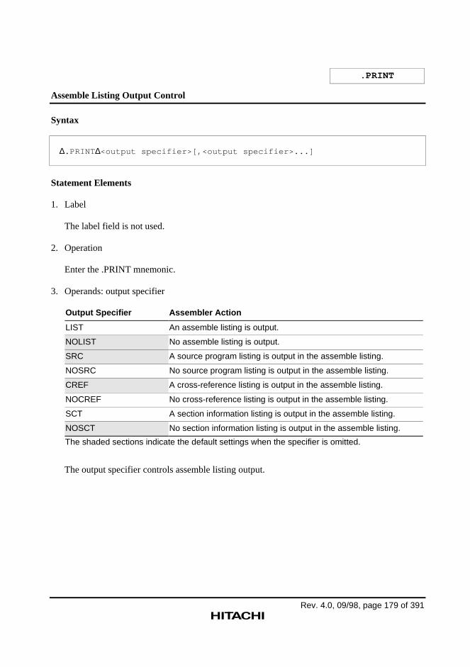
Rev. 4.0, 09/98, page 179 of 391
Assemble Listing Output Control
Syntax
∆.PRINT ∆<output specifier>[,<output specifier>...]
Statement Elements
1. Label
The label field is not used.
2. Operation
Enter the .PRINT mnemonic.
3. Operands: output specifier
Output Specifier Assembler Action
LIST An assemble listing is output.
NOLIST No assemble listing is output.
SRC A source program listing is output in the assemble listing.
NOSRC No source program listing is output in the assemble listing.
CREF A cross-reference listing is output in the assemble listing.
NOCREF No cross-reference listing is output in the assemble listing.
SCT A section information listing is output in the assemble listing.
NOSCT No section information listing is output in the assemble listing.
The shaded sections indicate the default settings when the specifier is omitted.
The output specifier controls assemble listing output.
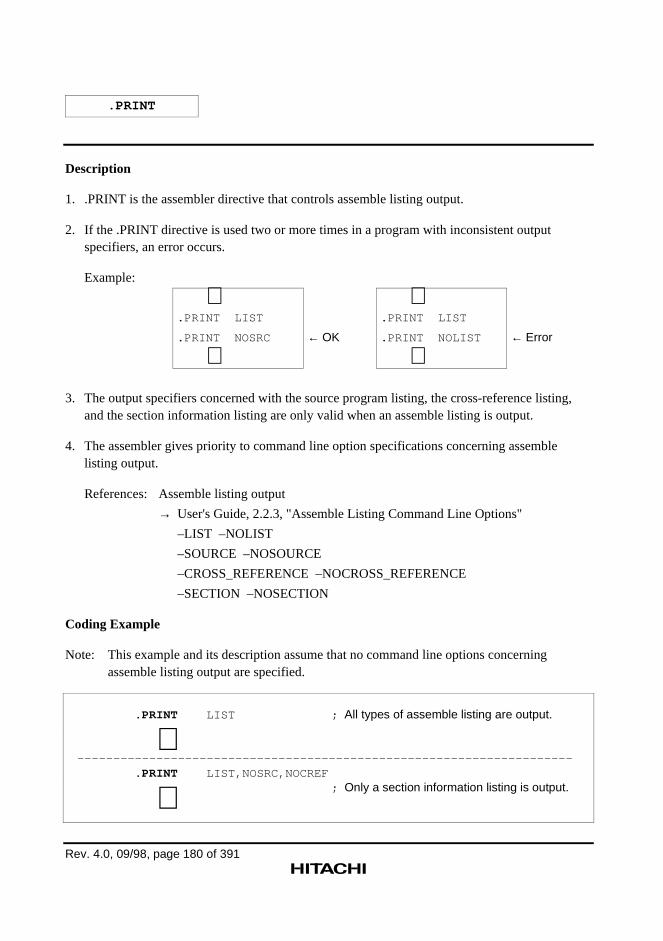
Rev. 4.0, 09/98, page 180 of 391
Description
1. .PRINT is the assembler directive that controls assemble listing output.
2. If the .PRINT directive is used two or more times in a program with inconsistent outputspecifiers, an error occurs.
Example:
∼.PRINT LIST
.PRINT NOSRC
∼← OK
∼.PRINT LIST
.PRINT NOLIST
∼← Error
3. The output specifiers concerned with the source program listing, the cross-reference listing,and the section information listing are only valid when an assemble listing is output.
4. The assembler gives priority to command line option specifications concerning assemblelisting output.
References: Assemble listing output
→ User's Guide, 2.2.3, "Assemble Listing Command Line Options"
–LIST –NOLIST
–SOURCE –NOSOURCE
–CROSS_REFERENCE –NOCROSS_REFERENCE
–SECTION –NOSECTION
Coding Example
Note: This example and its description assume that no command line options concerningassemble listing output are specified.
.PRINT LIST ; All types of assemble listing are output.
∼--------------------------------------------------------------------- .PRINT LIST,NOSRC,NOCREF
; Only a section information listing is output. ∼
Rev. 4.0, 09/98, page 181 of 391
.LIST
Source Program Listing Output Control
Syntax
∆.LIST ∆<output specifier>[,<output specifier>...]
Output specifier: {ON|OFF|COND|NOCOND|DEF|NODEF|CALL|NOCALL|
EXP|NOEXP|CODE|NOCODE}
Statement Elements
1. Label
The label field is not used.
2. Operation
Enter the .LIST mnemonic.
3. Operands
Enter the output specifiers.
Description
1. .LIST is the assembler directive that controls output of the source program listing in thefollowing three ways:
a Selects whether or not to output source statements.
b Selects whether or not to output source statements related to the conditional assembly andmacro functions.
c Selects whether or not to output object code lines.
.LIST
Rev. 4.0, 09/98, page 182 of 391
2. Output is controlled by output specifiers as follows:
Output Specifier
Type Output Not output Object Description
a ON OFF Source statements The source statements following this directive
b COND NOCOND Failed condition Condition-failed .AIF or .AIFDEF directivestatements
DEF NODEF Definition Macro definition statements.AREPEAT and .AWHILE definition statements.INCLUDE directive statements.ASSIGNA and .ASSSIGNC directivestatements
CALL NOCALL Call Macro call statements,.AIF, AIFDEF, and .AENDI directive statements
EXP NOEXP Expansion Macro expansion statements.AREPEAT and .AWHILE expansion statements
c CODE NOCODE Object code lines The object code lines exceeding the sourcestatement lines
The shaded sections indicate the default settings when the specifier is omitted.
3. The specification of the .LIST directive is only valid when an assemble listing is output.
References: Source program listing output
→ Programmer's Guide, 5.2.7, "Assemble Listing Assembler Directives",.PRINT
→ User's Guide, 2.2.3, "Assemble Listing Command Line Options",–LIST –NOLIST –SOURCE –NOSOURCE
4. The assembler gives priority to command line option specifications concerning source programlisting output.
Reference: Output on the source program listing
→ User's Guide, 2.2.3, "Assemble Listing Command Line Options"–SHOW –NOSHOW
5. .LIST directive statements themselves are not output on the source program listing.
.LIST
Rev. 4.0, 09/98, page 183 of 6
Coding Example
.LIST NOCOND,NODEF
.MACRO SHLRN COUNT,Rd
SHIFT .ASSIGNA \COUNT
.AIF \&SHIFT GE 16
SHLR16 \Rd
SHIFT .ASSIGNA \&SHIFT-16
.AENDI
.AIF \&SHIFT GE 8
SHLR8 \Rd
SHIFT .ASSIGNA \&SHIFT-8
.AENDI
.AIF \&SHIFT GE 4
SHLR2 \Rd
SHLR2 \Rd
SHIFT .ASSIGNA \&SHIFT-4
.AENDI
.AIF \&SHIFT GE 2
SHLR2 \Rd
SHIFT .ASSIGNA \&SHIFT-2
.AENDI
.AIF \&SHIFT GE 1
SHLR \Rd
.AENDI
.ENDM
SHLRN 23,R0
This statement controls source programlisting output.
Macro call
These statements define a general-purpose multiple-bit shift procedure as amacro instruction.
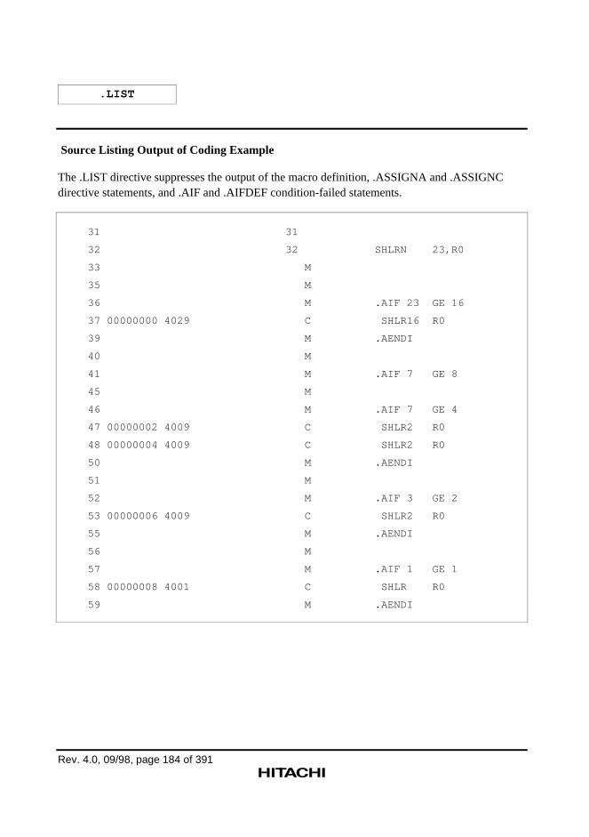
.LIST
Rev. 4.0, 09/98, page 184 of 391
Source Listing Output of Coding Example
The .LIST directive suppresses the output of the macro definition, .ASSIGNA and .ASSIGNCdirective statements, and .AIF and .AIFDEF condition-failed statements.
31 31
32 32 SHLRN 23,R0
33 M
35 M
36 M .AIF 23 GE 16
37 00000000 4029 C SHLR16 R0
39 M .AENDI
40 M
41 M .AIF 7 GE 8
45 M
46 M .AIF 7 GE 4
47 00000002 4009 C SHLR2 R0
48 00000004 4009 C SHLR2 R0
50 M .AENDI
51 M
52 M .AIF 3 GE 2
53 00000006 4009 C SHLR2 R0
55 M .AENDI
56 M
57 M .AIF 1 GE 1
58 00000008 4001 C SHLR R0
59 M .AENDI
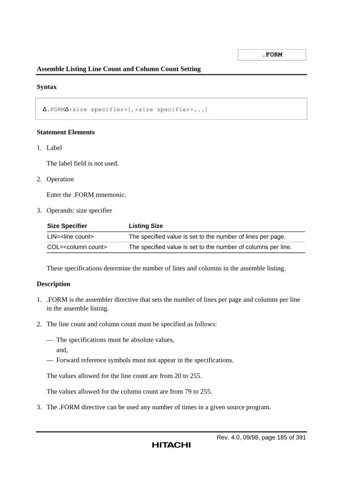
Rev. 4.0, 09/98, page 185 of 391
.FORM
Assemble Listing Line Count and Column Count Setting
Syntax
∆.FORM∆<size specifier>[,<size specifier>...]
Statement Elements
1. Label
The label field is not used.
2. Operation
Enter the .FORM mnemonic.
3. Operands: size specifier
Size Specifier Listing Size
LIN=<line count> The specified value is set to the number of lines per page.
COL=<column count> The specified value is set to the number of columns per line.
These specifications determine the number of lines and columns in the assemble listing.
Description
1. .FORM is the assembler directive that sets the number of lines per page and columns per linein the assemble listing.
2. The line count and column count must be specified as follows:
— The specifications must be absolute values,
and,
— Forward reference symbols must not appear in the specifications.
The values allowed for the line count are from 20 to 255.
The values allowed for the column count are from 79 to 255.
3. The .FORM directive can be used any number of times in a given source program.
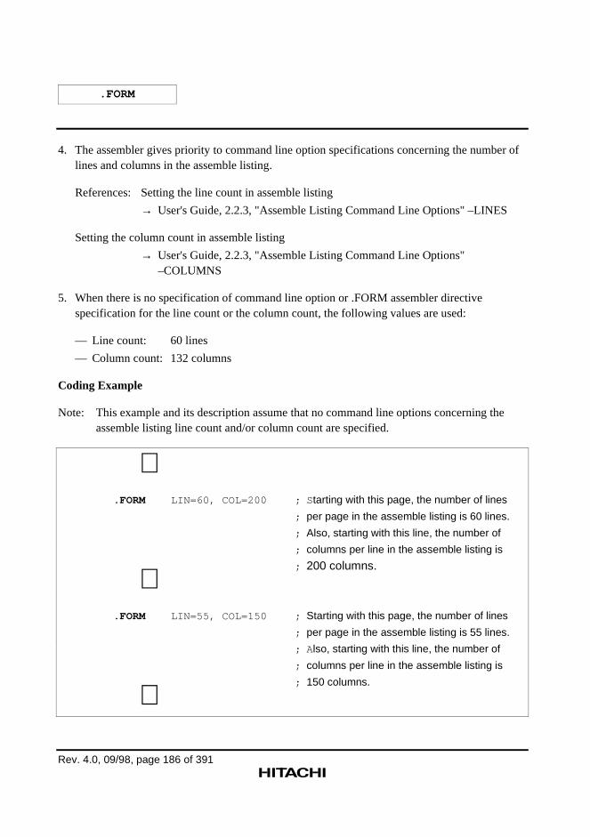
.FORM
Rev. 4.0, 09/98, page 186 of 391
4. The assembler gives priority to command line option specifications concerning the number oflines and columns in the assemble listing.
References: Setting the line count in assemble listing
→ User's Guide, 2.2.3, "Assemble Listing Command Line Options" –LINES
Setting the column count in assemble listing
→ User's Guide, 2.2.3, "Assemble Listing Command Line Options"–COLUMNS
5. When there is no specification of command line option or .FORM assembler directivespecification for the line count or the column count, the following values are used:
— Line count: 60 lines
— Column count: 132 columns
Coding Example
Note: This example and its description assume that no command line options concerning theassemble listing line count and/or column count are specified.
∼ .FORM LIN=60, COL=200 ; S tarting with this page, the number of lines
; per page in the assemble listing is 60 lines.
; Also, starting with this line, the number of
; columns per line in the assemble listing is
; 200 columns. ∼ .FORM LIN=55, COL=150 ; Starting with this page, the number of lines
; per page in the assemble listing is 55 lines.
; A lso, starting with this line, the number of
; columns per line in the assemble listing is
; 150 columns.
∼
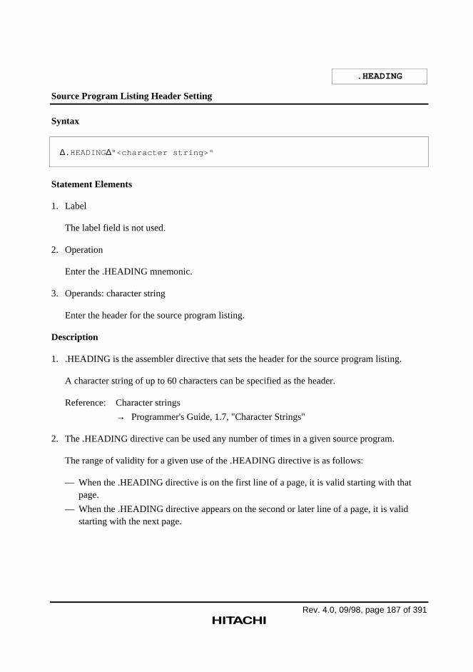
Rev. 4.0, 09/98, page 187 of 391
.HEADING
Source Program Listing Header Setting
Syntax
∆.HEADING∆"<character string>"
Statement Elements
1. Label
The label field is not used.
2. Operation
Enter the .HEADING mnemonic.
3. Operands: character string
Enter the header for the source program listing.
Description
1. .HEADING is the assembler directive that sets the header for the source program listing.
A character string of up to 60 characters can be specified as the header.
Reference: Character strings
→ Programmer's Guide, 1.7, "Character Strings"
2. The .HEADING directive can be used any number of times in a given source program.
The range of validity for a given use of the .HEADING directive is as follows:
— When the .HEADING directive is on the first line of a page, it is valid starting with thatpage.
— When the .HEADING directive appears on the second or later line of a page, it is validstarting with the next page.
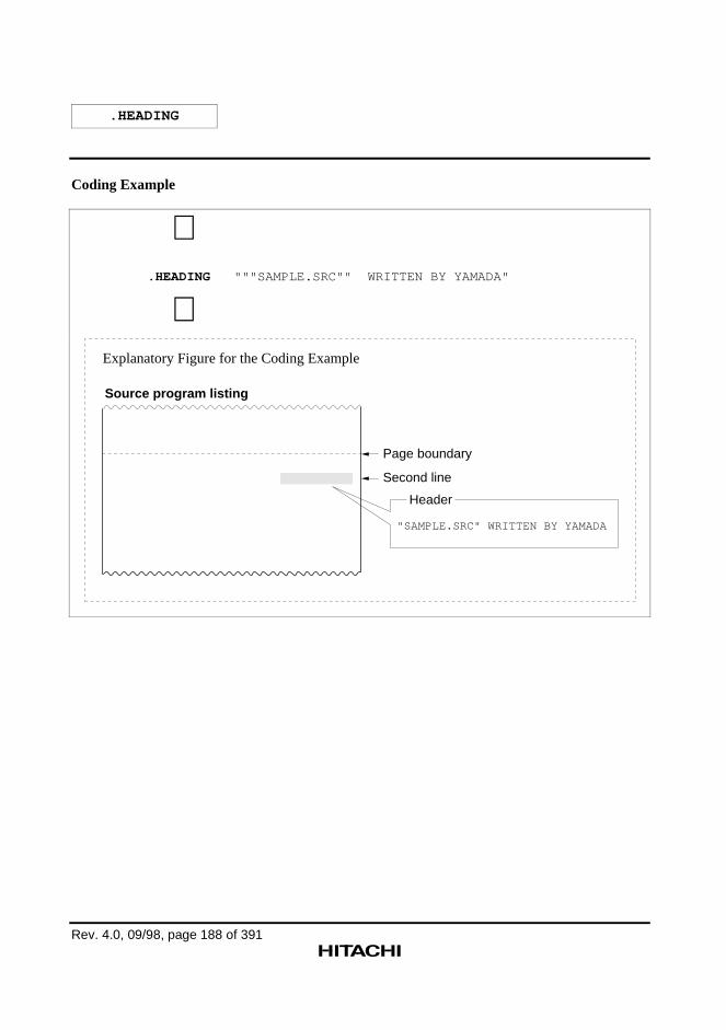
.HEADING
Rev. 4.0, 09/98, page 188 of 391
Coding Example
∼ .HEADING """SAMPLE.SRC"" WRITTEN BY YAMADA"
∼
"SAMPLE.SRC" WRITTEN BY YAMADA
Header
Source program listing
Page boundary
Second line
Explanatory Figure for the Coding Example
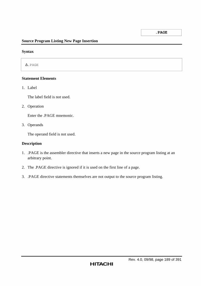
Rev. 4.0, 09/98, page 189 of 391
.PAGE
Source Program Listing New Page Insertion
Syntax
∆.PAGE
Statement Elements
1. Label
The label field is not used.
2. Operation
Enter the .PAGE mnemonic.
3. Operands
The operand field is not used.
Description
1. .PAGE is the assembler directive that inserts a new page in the source program listing at anarbitrary point.
2. The .PAGE directive is ignored if it is used on the first line of a page.
3. .PAGE directive statements themselves are not output to the source program listing.
.PAGE
Rev. 4.0, 09/98, page 190 of 391
Coding Example
∼ MOV R0,R1
RTS
MOV R0,R2
.PAGE ; A new page is specified here since the section changes at this point.
.SECTION DT,DATA,ALIGN=4
.DATA.L H'11111111
.DATA.L H'22222222
.DATA.L H'33333333
∼
18 00000022 6103 18 MOV R0,R1 19 00000024 000B 19 RTS 20 00000026 6203 20 MOV R0,R2
-----------------------------------------------------------------------------
*** SuperH RISC engine ASSEMBLER Ver. 4.0 *** 01/12/98 10:23:30 PROGRAM NAME =
22 00000000 22 .SECTION DT,DATA,ALIGN 23 00000000 11111111 23 .DATA.L H'11111111 24 00000004 22222222 24 .DATA.L H'22222222 25 00000008 33333333 25 .DATA.L H'33333333
Note:
Source program listing
New page
See appendix C, “Assemble Listing Output Example”, for an explanation of the contents of the source program listing.
Explanatory Figure for the Coding Example
Rev. 4.0, 09/98, page 191 of 391
.SPACE
Source Program Listing Blank Line Output
Syntax
∆.SPACE[ ∆<line count>]
Statement Elements
1. Label
The label field is not used.
2. Operation
Enter the .SPACE mnemonic.
3. Operands: line count
Enter the number of blank lines.
A single blank line is output if this operand is omitted.
Description
1. .SPACE is the assembler directive that outputs the specified number of blank lines to thesource program listing. Nothing is output for the lines output by the .SPACE directive; inparticular line numbers are not output for these lines.
2. The line count must be specified as follows:
— The specification must be an absolute value,
and,
— Forward reference symbols must not appear in the specification.
Values from 1 to 50 can be specified as the line count.
3. When a new page occurs as the result of blank lines output by the .SPACE directive, anyremaining blank lines are not output on the new page.
4. .SPACE directive statements themselves are not output to the source program listing.
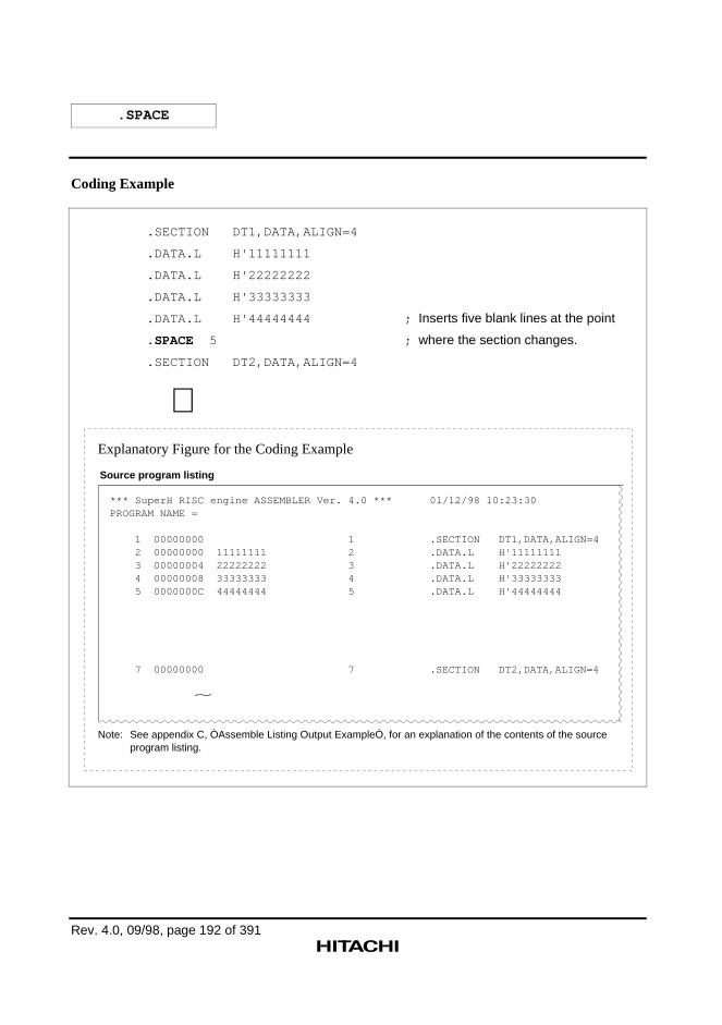
.SPACE
Rev. 4.0, 09/98, page 192 of 391
Coding Example
.SECTION DT1,DATA,ALIGN=4
.DATA.L H'11111111
.DATA.L H'22222222
.DATA.L H'33333333
.DATA.L H'44444444 ; Inserts five blank lines at the point
.SPACE 5 ; where the section changes.
.SECTION DT2,DATA,ALIGN=4
∼
*** SuperH RISC engine ASSEMBLER Ver. 4.0 *** 01/12/98 10:23:30PROGRAM NAME =
1 00000000 1 .SECTION DT1,DATA,ALIGN=4 2 00000000 11111111 2 .DATA.L H'11111111 3 00000004 22222222 3 .DATA.L H'22222222 4 00000008 33333333 4 .DATA.L H'33333333 5 0000000C 44444444 5 .DATA.L H'44444444
7 00000000 7 .SECTION DT2,DATA,ALIGN=4
~
Note:
Source program listing
See appendix C, ÒAssemble Listing Output ExampleÓ, for an explanation of the contents of the source program listing.
Explanatory Figure for the Coding Example
Rev. 4.0, 09/98, page 193 of 391
5.2.8 Other Assembler Directives
This assembler provides the following additional assembler directives.
.PROGRAM
Sets the name of the object module.
.RADIX
Sets the radix in which integer constants with no radix specifier are interpreted.
.END
Declares the end of the source program.
Rev. 4.0, 09/98, page 194 of 391
.PROGRAM
Object Module Name Setting
Syntax
∆.PROGRAM∆<object module name>
Statement Elements
1. Label
The label field is not used.
2. Operation
Enter the .PROGRAM mnemonic.
3. Operands: <object module name>
Enter a name that identifies the object module.
Description
1. .PROGRAM is the assembler directive that sets the object module name.
The object module name is a name that is required by the H Series Linkage Editor or the HSeries Librarian to identify the object module.
2. Object module naming conventions are the same as symbol naming conventions.
The assembler distinguishes upper-case and lower-case letter in object module names.
Reference: Coding of symbols
→ Programmer's Guide, 1.3.2, "Coding of Symbols"
3. Setting the object module name with the .PROGRAM directive is valid only once in a givenprogram. (The assembler ignores the second and later specifications of the .PROGRAMdirective.)
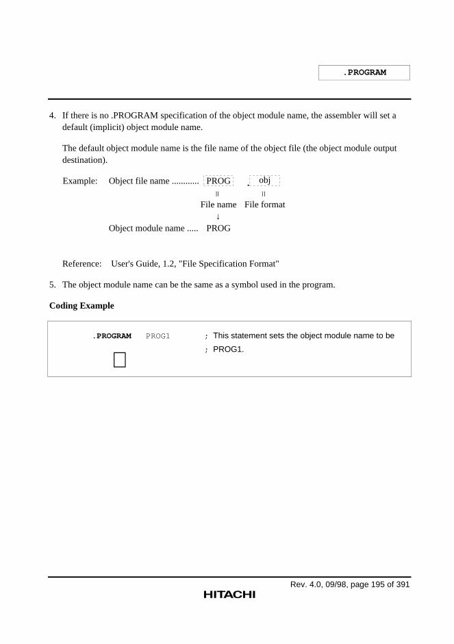
.PROGRAM
Rev. 4.0, 09/98, page 195 of 391
4. If there is no .PROGRAM specification of the object module name, the assembler will set adefault (implicit) object module name.
The default object module name is the file name of the object file (the object module outputdestination).
Example: Object file name ............
Object module name .....
PROG
File name↓
PROG=
obj
File format
=
·
Reference: User's Guide, 1.2, "File Specification Format"
5. The object module name can be the same as a symbol used in the program.
Coding Example
.PROGRAM PROG1 ; This statement sets the object module name to be
; PROG1.
∼
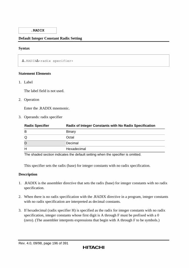
Rev. 4.0, 09/98, page 196 of 391
.RADIX
Default Integer Constant Radix Setting
Syntax
∆.RADIX ∆<radix specifier>
Statement Elements
1. Label
The label field is not used.
2. Operation
Enter the .RADIX mnemonic.
3. Operands: radix specifier
Radix Specifier Radix of Integer Constants with No Radix Specification
B Binary
Q Octal
D Decimal
H Hexadecimal
The shaded section indicates the default setting when the specifier is omitted.
This specifier sets the radix (base) for integer constants with no radix specification.
Description
1. .RADIX is the assembler directive that sets the radix (base) for integer constants with no radixspecification.
2. When there is no radix specification with the .RADIX directive in a program, integer constantswith no radix specification are interpreted as decimal constants.
3. If hexadecimal (radix specifier H) is specified as the radix for integer constants with no radixspecification, integer constants whose first digit is A through F must be prefixed with a 0(zero). (The assembler interprets expressions that begin with A through F to be symbols.)
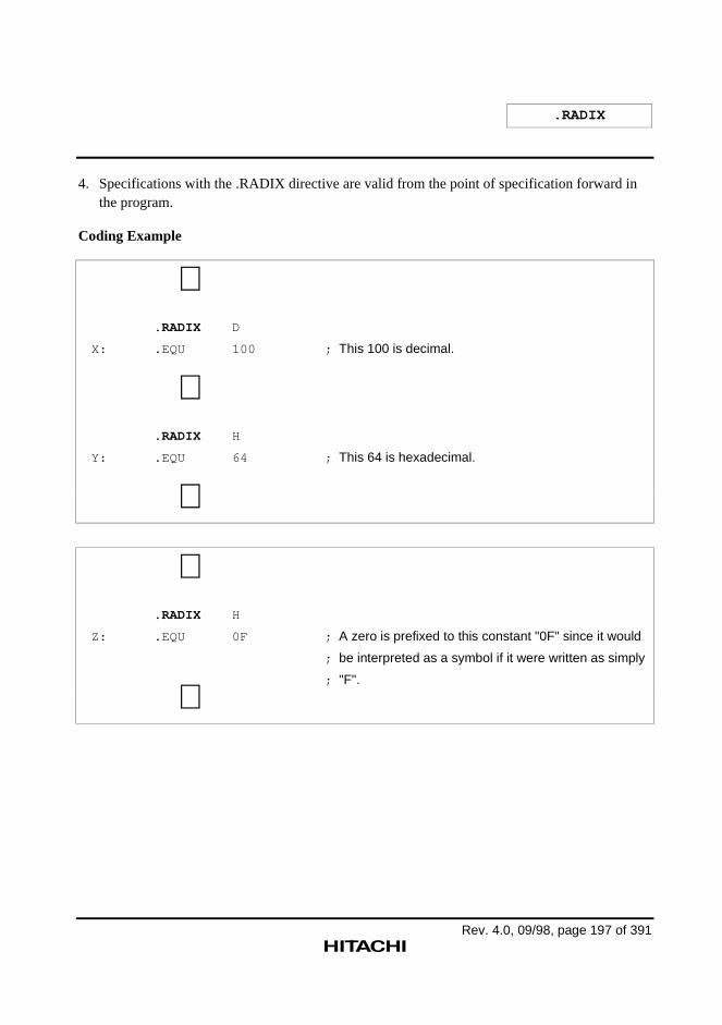
.RADIX
Rev. 4.0, 09/98, page 197 of 391
4. Specifications with the .RADIX directive are valid from the point of specification forward inthe program.
Coding Example
∼ .RADIX D
X: .EQU 100 ; This 100 is decimal.
∼ .RADIX H
Y: .EQU 64 ; This 64 is hexadecimal.
∼
∼ .RADIX H
Z: .EQU 0F ; A zero is prefixed to this constant "0F" since it would
; be interpreted as a symbol if it were written as simply
; "F".
∼
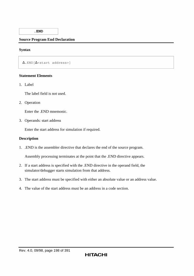
Rev. 4.0, 09/98, page 198 of 391
.END
Source Program End Declaration
Syntax
∆.END[ ∆<start address>]
Statement Elements
1. Label
The label field is not used.
2. Operation
Enter the .END mnemonic.
3. Operands: start address
Enter the start address for simulation if required.
Description
1. .END is the assembler directive that declares the end of the source program.
Assembly processing terminates at the point that the .END directive appears.
2. If a start address is specified with the .END directive in the operand field, thesimulator/debugger starts simulation from that address.
3. The start address must be specified with either an absolute value or an address value.
4. The value of the start address must be an address in a code section.
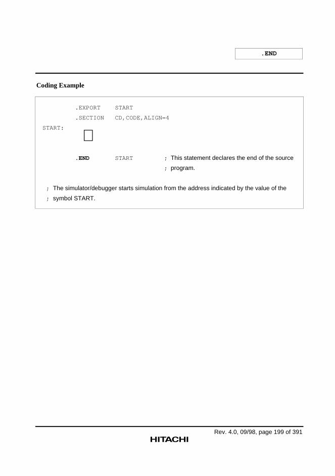
.END
Rev. 4.0, 09/98, page 199 of 391
Coding Example
.EXPORT START
.SECTION CD,CODE,ALIGN=4
START:
∼ .END START ; This statement declares the end of the source
; program.
; The simulator/debugger starts simulation from the address indicated by the value of the
; symbol START.
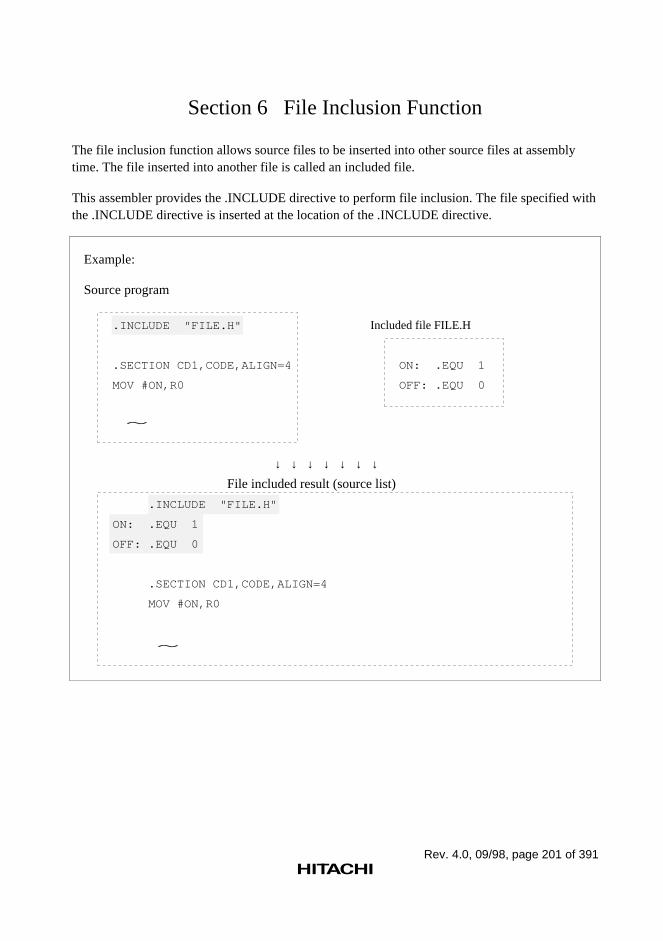
Rev. 4.0, 09/98, page 201 of 391
Section 6 File Inclusion Function
The file inclusion function allows source files to be inserted into other source files at assemblytime. The file inserted into another file is called an included file.
This assembler provides the .INCLUDE directive to perform file inclusion. The file specified withthe .INCLUDE directive is inserted at the location of the .INCLUDE directive.
Example:
Source program
.INCLUDE "FILE.H" Included file FILE.H
.SECTION CD1,CODE,ALIGN=4 ON: .EQU 1
MOV #ON,R0 OFF: .EQU 0
↓ ↓ ↓ ↓ ↓ ↓ ↓
File included result (source list)
.INCLUDE "FILE.H"
ON: .EQU 1
OFF: .EQU 0
.SECTION CD1,CODE,ALIGN=4
MOV #ON,R0
~
~
Rev. 4.0, 09/98, page 202 of 391
.INCLUDE
File Inclusion
Syntax
∆.INCLUDE ∆"<file name>"
Statement Elements
1. Label
The label field is not used.
2. Operation
Enter the .INCLUDE mnemonic.
3. Operands
Enter the file to be included.
Description
1. .INCLUDE is the file inclusion assembler directive.
2. If no file format is specified, only the file name is used as specified (the assembler does notassume any default file format).
Reference: User's Guide, 1.2, "File Specification Format"
3. The file name can include the directory. The directory can be specified either by the absolutepath (path from the route directory) or by the relative path (path from the current directory).
Note: The current directory for the .INCLUDE directive in a source file is the directorywhere the assembler is initiated. The current directory for the .INCLUDE directive inan included file is the directory where the included file exits.
4. Included files can include other files. The nesting depth for file inclusion is limited to 30 levels(multiplex state).
5. The directory name specified by .INCLUDE can be changed by –INCLUDE.
Reference: –INCLUDE→ User's Guide, 2.2.4, "File Inclusion Function Command Line Option"
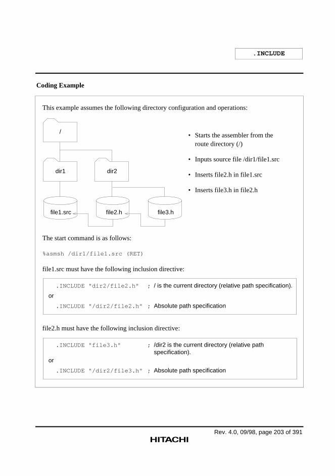
.INCLUDE
Rev. 4.0, 09/98, page 203 of 391
Coding Example
This example assumes the following directory configuration and operations:
dir1 dir2
file1.src file2.h file3.h
/ • Starts the assembler from the route directory (/)
• Inputs source file /dir1/file1.src
• Inserts file2.h in file1.src
• Inserts file3.h in file2.h
The start command is as follows:
%asmsh /dir1/file1.src (RET)
file1.src must have the following inclusion directive:
.INCLUDE "dir2/file2.h" ; / is the current directory (relative path specification).
or
.INCLUDE "/dir2/file2.h" ; Absolute path specification
file2.h must have the following inclusion directive:
.INCLUDE "file3.h" ; /dir2 is the current directory (relative pathspecification).
or
.INCLUDE "/dir2/file3.h" ; Absolute path specification
.INCLUDE
Rev. 4.0, 09/98, page 204 of 391
CAUTION!
When using Windows®95 or Windows®NT, change the slash (/) in the above example as followsdepending on the environment.
• Japanese environment: Yen mark (¥)
• English environment: Backslash (\)
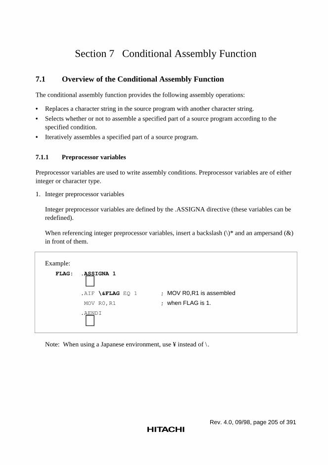
Rev. 4.0, 09/98, page 205 of 391
Section 7 Conditional Assembly Function
7.1 Overview of the Conditional Assembly Function
The conditional assembly function provides the following assembly operations:
• Replaces a character string in the source program with another character string.
• Selects whether or not to assemble a specified part of a source program according to thespecified condition.
• Iteratively assembles a specified part of a source program.
7.1.1 Preprocessor variables
Preprocessor variables are used to write assembly conditions. Preprocessor variables are of eitherinteger or character type.
1. Integer preprocessor variables
Integer preprocessor variables are defined by the .ASSIGNA directive (these variables can beredefined).
When referencing integer preprocessor variables, insert a backslash (\)* and an ampersand (&)in front of them.
Example:
FLAG: .ASSIGNA 1
∼ .AIF \&FLAG EQ 1 ; MOV R0,R1 is assembled
MOV R0,R1 ; when FLAG is 1.
.AENDI
∼Note: When using a Japanese environment, use ¥ instead of \ .
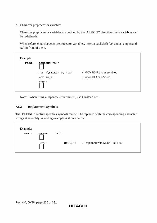
Rev. 4.0, 09/98, page 206 of 391
2. Character preprocessor variables
Character preprocessor variables are defined by the .ASSIGNC directive (these variables canbe redefined).
When referencing character preprocessor variables, insert a backslash (\)* and an ampersand(&) in front of them.
Example:
FLAG: .ASSIGNC "ON"
∼ .AIF " \&FLAG" EQ "ON" ; MOV R0,R1 is assembled
MOV R0,R1 ; when FLAG is "ON".
.AENDI
∼Note: When using a Japanese environment, use ¥ instead of \ .
7.1.2 Replacement Symbols
The .DEFINE directive specifies symbols that will be replaced with the corresponding characterstrings at assembly. A coding example is shown below.
Example:
SYM1: .DEFINE "R1"
∼ MOV.L SYM1,R0 ; Replaced with MOV.L R1,R0.
∼
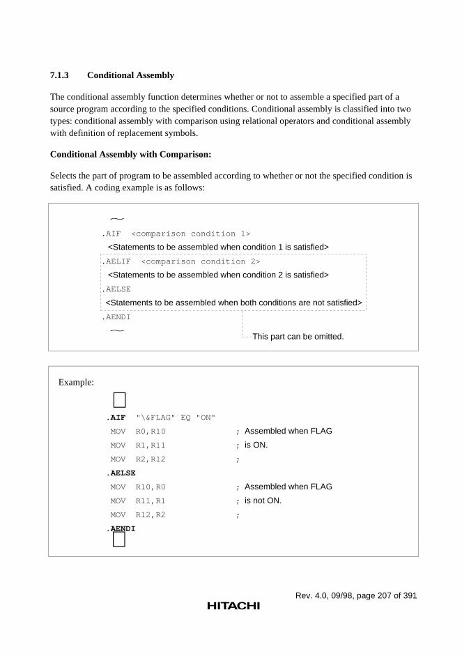
Rev. 4.0, 09/98, page 207 of 391
7.1.3 Conditional Assembly
The conditional assembly function determines whether or not to assemble a specified part of asource program according to the specified conditions. Conditional assembly is classified into twotypes: conditional assembly with comparison using relational operators and conditional assemblywith definition of replacement symbols.
Conditional Assembly with Comparison:
Selects the part of program to be assembled according to whether or not the specified condition issatisfied. A coding example is as follows:
.AIF <comparison condition 1>
<Statements to be assembled when condition 1 is satisfied>
.AELIF <comparison condition 2>
<Statements to be assembled when condition 2 is satisfied>
.AELSE
<Statements to be assembled when both conditions are not satisfied>
.AENDI
~
~This part can be omitted.
Example:
∼.AIF "\&FLAG" EQ "ON"
MOV R0,R10 ; Assembled when FLAG
MOV R1,R11 ; is ON.
MOV R2,R12 ;
.AELSE
MOV R10,R0 ; Assembled when FLAG
MOV R11,R1 ; is not ON.
MOV R12,R2 ;
.AENDI
∼
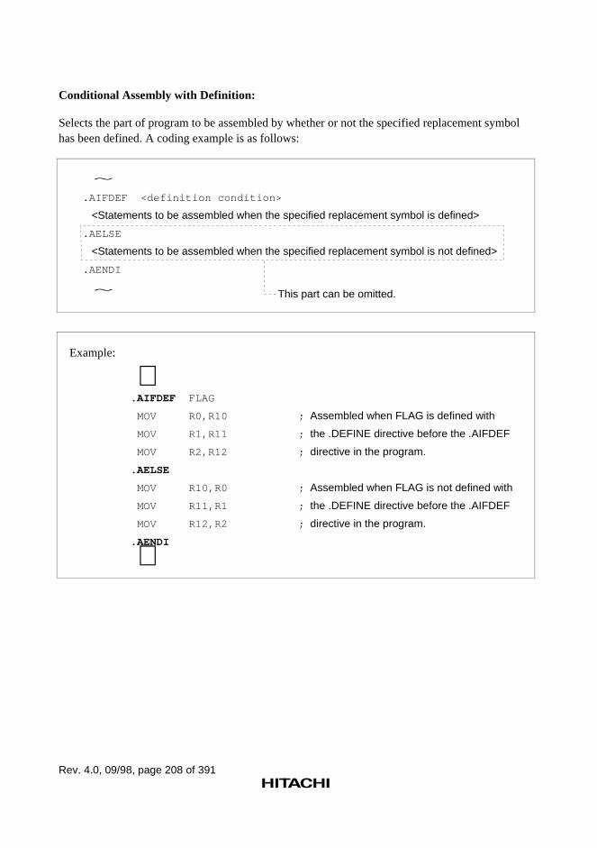
Rev. 4.0, 09/98, page 208 of 391
Conditional Assembly with Definition:
Selects the part of program to be assembled by whether or not the specified replacement symbolhas been defined. A coding example is as follows:
.AIFDEF <definition condition>
<Statements to be assembled when the specified replacement symbol is defined>
.AELSE
<Statements to be assembled when the specified replacement symbol is not defined>
.AENDI
~
~ This part can be omitted.
Example:
∼.AIFDEF FLAG
MOV R0,R10 ; Assembled when FLAG is defined with
MOV R1,R11 ; the .DEFINE directive before the .AIFDEF
MOV R2,R12 ; directive in the program.
.AELSE
MOV R10,R0 ; Assembled when FLAG is not defined with
MOV R11,R1 ; the .DEFINE directive before the .AIFDEF
MOV R12,R2 ; directive in the program.
.AENDI
∼
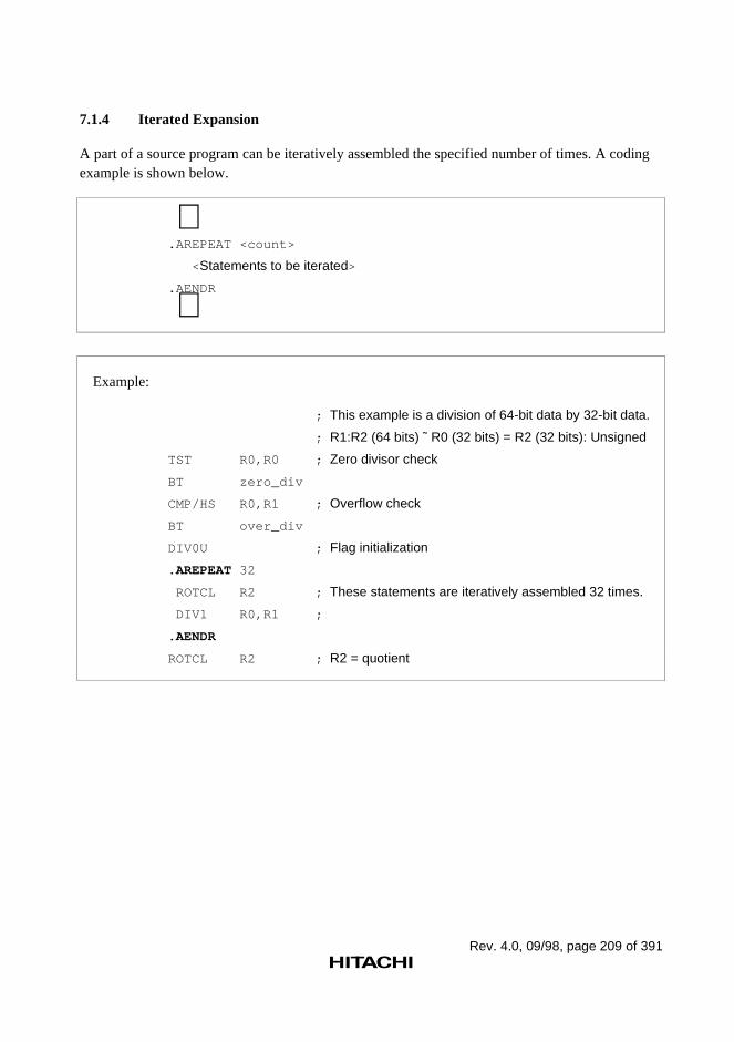
Rev. 4.0, 09/98, page 209 of 391
7.1.4 Iterated Expansion
A part of a source program can be iteratively assembled the specified number of times. A codingexample is shown below.
∼.AREPEAT <count>
< Statements to be iterated>
.AENDR
∼
Example:
; This example is a division of 64-bit data by 32-bit data.
; R1:R2 (64 bits) ˜ R0 (32 bits) = R2 (32 bits): Unsigned
TST R0,R0 ; Zero divisor check
BT zero_div
CMP/HS R0,R1 ; Overflow check
BT over_div
DIV0U ; Flag initialization
.AREPEAT 32
ROTCL R2 ; These statements are iteratively assembled 32 times.
DIV1 R0,R1 ;
.AENDR
ROTCL R2 ; R2 = quotient
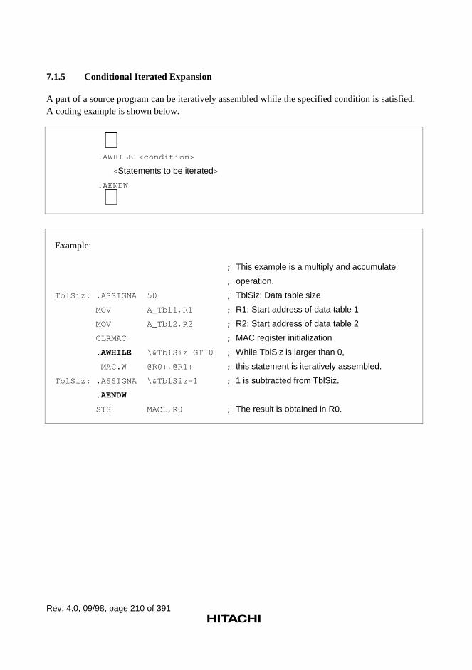
Rev. 4.0, 09/98, page 210 of 391
7.1.5 Conditional Iterated Expansion
A part of a source program can be iteratively assembled while the specified condition is satisfied.A coding example is shown below.
∼.AWHILE <condition>
< Statements to be iterated>
.AENDW
∼
Example:
; This example is a multiply and accumulate
; operation.
TblSiz: .ASSIGNA 50 ; TblSiz: Data table size
MOV A_Tbl1,R1 ; R1: Start address of data table 1
MOV A_Tbl2,R2 ; R2: Start address of data table 2
CLRMAC ; MAC register initialization
.AWHILE \&TblSiz GT 0 ; While TblSiz is larger than 0,
MAC.W @R0+,@R1+ ; this statement is iteratively assembled.
TblSiz: .ASSIGNA \&TblSiz-1 ; 1 is subtracted from TblSiz.
.AENDW
STS MACL,R0 ; The result is obtained in R0.
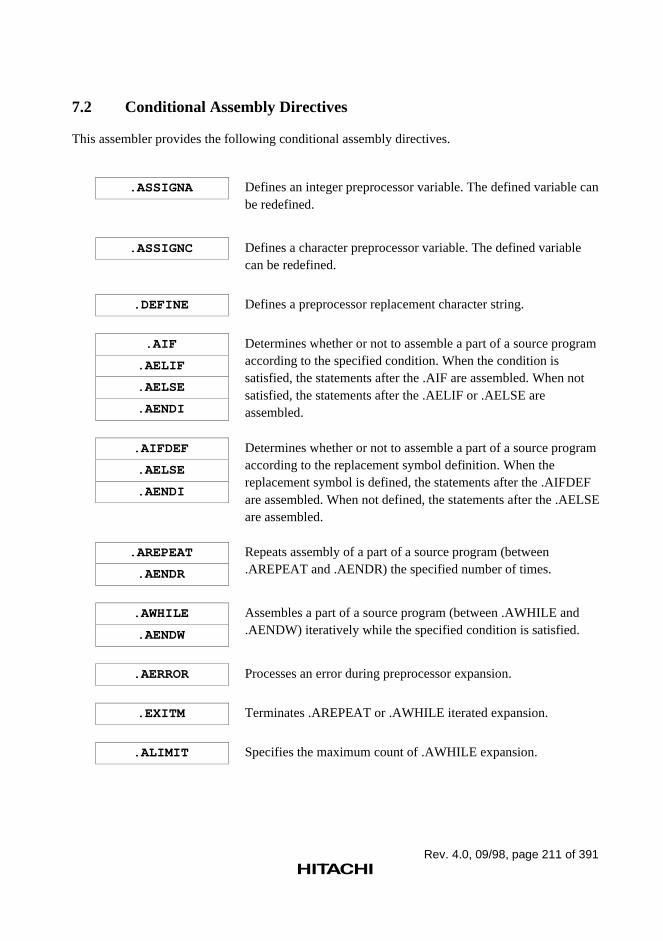
Rev. 4.0, 09/98, page 211 of 391
7.2 Conditional Assembly Directives
This assembler provides the following conditional assembly directives.
.ASSIGNA Defines an integer preprocessor variable. The defined variable canbe redefined.
.ASSIGNC Defines a character preprocessor variable. The defined variablecan be redefined.
.DEFINE Defines a preprocessor replacement character string.
.AIF
.AELIF
.AELSE
.AENDI
Determines whether or not to assemble a part of a source programaccording to the specified condition. When the condition issatisfied, the statements after the .AIF are assembled. When notsatisfied, the statements after the .AELIF or .AELSE areassembled.
.AIFDEF
.AELSE
.AENDI
Determines whether or not to assemble a part of a source programaccording to the replacement symbol definition. When thereplacement symbol is defined, the statements after the .AIFDEFare assembled. When not defined, the statements after the .AELSEare assembled.
.AREPEAT
.AENDR
Repeats assembly of a part of a source program (between.AREPEAT and .AENDR) the specified number of times.
.AWHILE
.AENDW
Assembles a part of a source program (between .AWHILE and.AENDW) iteratively while the specified condition is satisfied.
.AERROR Processes an error during preprocessor expansion.
.EXITM Terminates .AREPEAT or .AWHILE iterated expansion.
.ALIMIT Specifies the maximum count of .AWHILE expansion.

Rev. 4.0, 09/98, page 212 of 391
.ASSIGNA
Integer Preprocessor Variable Definition (Redefinition Is Possible)
Syntax
<preprocessor variable>[:] ∆.ASSIGNA∆<value>
Statement Elements
1. Label
Enter the name of the preprocessor variable.
2. Operation
Enter the .ASSIGNA mnemonic.
3. Operands
Enter the value to be assigned to the preprocessor variable.
Description
1. .ASSIGNA is the assembler directive that defines a value for an integer preprocessor variable.The syntax of integer preprocessor variables is the same as that for symbols. An integerpreprocessor variable can be defined with up to 32 characters, and uppercase and lowercaseletters are distinguished.
2. The preprocessor variables defined with the .ASSIGNA directive can be redefined with the.ASSIGNA directive.
3. The values for the preprocessor variables must be the following:
— Constant (integer constant and character constant)
— Defined preprocessor variable
— Expression using the above as terms
4. Defined preprocessor variables are valid from the point of specification forward in the sourceprogram.
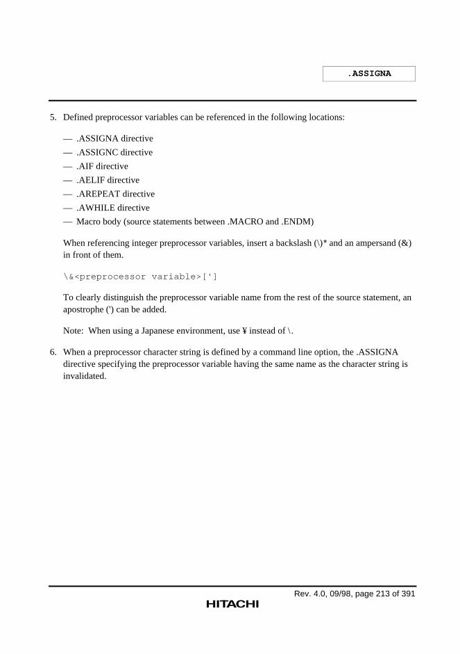
.ASSIGNA
Rev. 4.0, 09/98, page 213 of 391
5. Defined preprocessor variables can be referenced in the following locations:
— .ASSIGNA directive
— .ASSIGNC directive
— .AIF directive
— .AELIF directive
— .AREPEAT directive
— .AWHILE directive
— Macro body (source statements between .MACRO and .ENDM)
When referencing integer preprocessor variables, insert a backslash (\)* and an ampersand (&)in front of them.
\&<preprocessor variable>[']
To clearly distinguish the preprocessor variable name from the rest of the source statement, anapostrophe (') can be added.
Note: When using a Japanese environment, use ¥ instead of \ .
6. When a preprocessor character string is defined by a command line option, the .ASSIGNAdirective specifying the preprocessor variable having the same name as the character string isinvalidated.
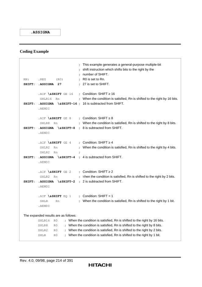
.ASSIGNA
Rev. 4.0, 09/98, page 214 of 391
Coding Example
; This example generates a general-purpose multiple-bit
; shift instruction which shifts bits to the right by the
; number of SHIFT.
RN: .REG (R0) ; R0 is set to Rn.
SHIFT: .ASSIGNA 27 ; 27 is set to SHIFT.
.AIF \&SHIFT GE 16 ; Condition: SHIFT ≥ 16
SHLR16 Rn ; When the condition is satisfied, Rn is shifted to the right by 16 bits.
SHIFT: .ASSIGNA \&SHIFT-16 ; 16 is subtracted from SHIFT.
.AENDI
.AIF \&SHIFT GE 8 ; Condition: SHIFT ≥ 8
SHLR8 Rn ; When the condition is satisfied, Rn is shifted to the right by 8 bits.
SHIFT: .ASSIGNA \&SHIFT-8 ; 8 is subtracted from SHIFT.
.AENDI
.AIF \&SHIFT GE 4 ; Condition: SHIFT ≥ 4
SHLR2 Rn ; When the condition is satisfied, Rn is shifted to the right by 4 bits.
SHLR2 Rn ;
SHIFT: .ASSIGNA \&SHIFT-4 ; 4 is subtracted from SHIFT.
.AENDI
.AIF \&SHIFT GE 2 ; Condition: SHIFT ≥ 2
SHLR2 Rn ; W hen the condition is satisfied, Rn is shifted to the right by 2 bits.
SHIFT: .ASSIGNA \&SHIFT-2 ; 2 is subtracted from SHIFT.
.AENDI
.AIF \&SHIFT EQ 1 ; Condition: SHIFT = 1
SHLR Rn ; When the condition is satisfied, Rn is shifted to the right by 1 bit.
.AENDI
The expanded results are as follows:
SHLR16 R0 ; When the condition is satisfied, Rn is shifted to the right by 16 bits.
SHLR8 R0 ; When the condition is satisfied, Rn is shifted to the right by 8 bits.
SHLR2 R0 ; When the condition is satisfied, Rn is shifted to the right by 2 bits.
SHLR R0 ; When the condition is satisfied, Rn is shifted to the right by 1 bit.
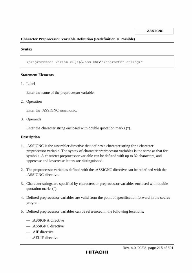
Rev. 4.0, 09/98, page 215 of 391
.ASSIGNC
Character Preprocessor Variable Definition (Redefinition Is Possible)
Syntax
<preprocessor variable>[:] ∆.ASSIGNC∆"<character string>"
Statement Elements
1. Label
Enter the name of the preprocessor variable.
2. Operation
Enter the .ASSIGNC mnemonic.
3. Operands
Enter the character string enclosed with double quotation marks (").
Description
1. .ASSIGNC is the assembler directive that defines a character string for a characterpreprocessor variable. The syntax of character preprocessor variables is the same as that forsymbols. A character preprocessor variable can be defined with up to 32 characters, anduppercase and lowercase letters are distinguished.
2. The preprocessor variables defined with the .ASSIGNC directive can be redefined with the.ASSIGNC directive.
3. Character strings are specified by characters or preprocessor variables enclosed with doublequotation marks (").
4. Defined preprocessor variables are valid from the point of specification forward in the sourceprogram.
5. Defined preprocessor variables can be referenced in the following locations:
— .ASSIGNA directive
— .ASSIGNC directive
— .AIF directive
— .AELIF directive
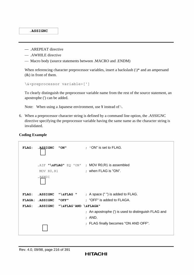
.ASSIGNC
Rev. 4.0, 09/98, page 216 of 391
— .AREPEAT directive
— .AWHILE directive
— Macro body (source statements between .MACRO and .ENDM)
When referencing character preprocessor variables, insert a backslash (\)* and an ampersand(&) in front of them.
\&<preprocessor variable>[']
To clearly distinguish the preprocessor variable name from the rest of the source statement, anapostrophe (') can be added.
Note: When using a Japanese environment, use ¥ instead of \ .
6. When a preprocessor character string is defined by a command line option, the .ASSIGNCdirective specifying the preprocessor variable having the same name as the character string isinvalidated.
Coding Example
FLAG: .ASSIGNC "ON" ; " ON" is set to FLAG.
∼ .AIF "\&FLAG" EQ "ON" ; MOV R0,R1 is assembled
MOV R0,R1 ; when FLAG is "ON".
.AENDI
∼FLAG: .ASSIGNC "\&FLAG " ; A space (" ") is added to FLAG.
FLAGA: .ASSIGNC "OFF" ; "OFF" is added to FLAGA.
FLAG: .ASSIGNC "\&FLAG'AND \&FLAGA"
; An apostrophe (') is used to distinguish FLAG and
; AND.
; FLAG finally becomes "ON AND OFF".
∼
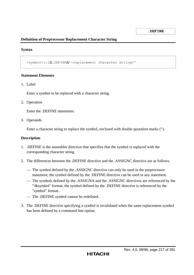
Rev. 4.0, 09/98, page 217 of 391
.DEFINE
Definition of Preprocessor Replacement Character String
Syntax
<symbol>[:] ∆.DEFINE ∆"<replacement character string>"
Statement Elements
1. Label
Enter a symbol to be replaced with a character string.
2. Operation
Enter the .DEFINE mnemonic.
3. Operands
Enter a character string to replace the symbol, enclosed with double quotation marks (").
Description
1. .DEFINE is the assembler directive that specifies that the symbol is replaced with thecorresponding character string.
2. The differences between the .DEFINE directive and the .ASSIGNC directive are as follows.
— The symbol defined by the .ASSIGNC directive can only be used in the preprocessorstatement; the symbol defined by the .DEFINE directive can be used in any statement.
— The symbols defined by the .ASSIGNA and the .ASSIGNC directives are referenced by the"\&symbol" format; the symbol defined by the .DEFINE directive is referenced by the"symbol" format.
— The .DEFINE symbol cannot be redefined.
3. The .DEFINE directive specifying a symbol is invalidated when the same replacement symbolhas been defined by a command line option.
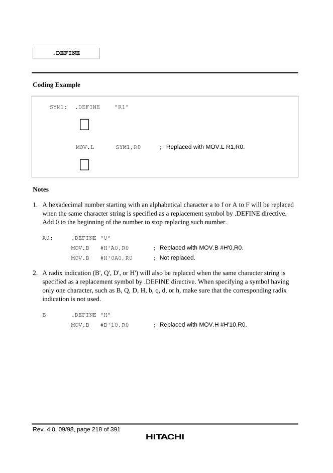
.DEFINE
Rev. 4.0, 09/98, page 218 of 391
Coding Example
SYM1: .DEFINE "R1"
∼ MOV.L SYM1,R0 ; Replaced with MOV.L R1,R0.
∼Notes
1. A hexadecimal number starting with an alphabetical character a to f or A to F will be replacedwhen the same character string is specified as a replacement symbol by .DEFINE directive.Add 0 to the beginning of the number to stop replacing such number.
A0: .DEFINE "0"
MOV.B #H'A0,R0 ; Replaced with MOV.B #H'0,R0.
MOV.B #H'0A0,R0 ; Not replaced.
2. A radix indication (B', Q', D', or H') will also be replaced when the same character string isspecified as a replacement symbol by .DEFINE directive. When specifying a symbol havingonly one character, such as B, Q, D, H, b, q, d, or h, make sure that the corresponding radixindication is not used.
B .DEFINE "H"
MOV.B #B'10,R0 ; Replaced with MOV.H #H'10,R0.
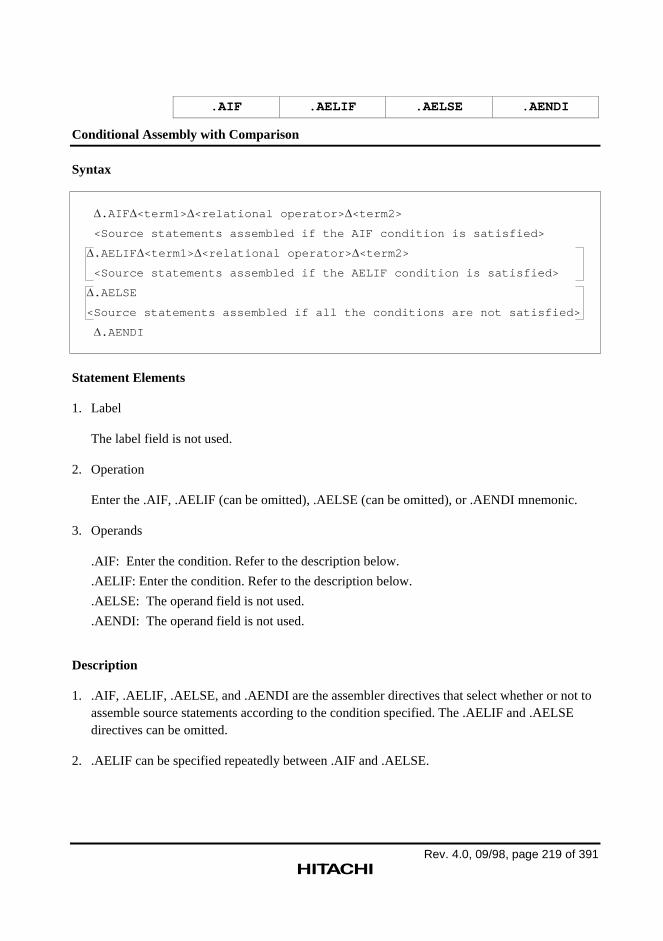
Rev. 4.0, 09/98, page 219 of 391
.AIF .AELIF .AELSE .AENDI
Conditional Assembly with Comparison
Syntax
.AIF <term1> <relational operator> <term2>
<Source statements assembled if the AIF condition is satisfied>
.AELIF <term1> <relational operator> <term2>
<Source statements assembled if the AELIF condition is satisfied>
.AELSE
<Source statements assembled if all the conditions are not satisfied>
.AENDI
Statement Elements
1. Label
The label field is not used.
2. Operation
Enter the .AIF, .AELIF (can be omitted), .AELSE (can be omitted), or .AENDI mnemonic.
3. Operands
.AIF: Enter the condition. Refer to the description below.
.AELIF: Enter the condition. Refer to the description below.
.AELSE: The operand field is not used.
.AENDI: The operand field is not used.
Description
1. .AIF, .AELIF, .AELSE, and .AENDI are the assembler directives that select whether or not toassemble source statements according to the condition specified. The .AELIF and .AELSEdirectives can be omitted.
2. .AELIF can be specified repeatedly between .AIF and .AELSE.
.AIF .AELIF .AELSE .AENDI
Rev. 4.0, 09/98, page 220 of 391
3. The condition must be specified as follows:
.AIF∆<term1>∆<relational operator>∆<term2>
.AELIF∆<term1>∆<relational operator>∆<term2>
Terms are specified with numeric values or character strings. However, when a numeric valueand a character string are compared, the condition always fails.
Numeric values are specified by constants or preprocessor variables.
Character strings are specified by characters or preprocessor variables enclosed with doublequotation marks ("). To specify a double quotation mark in a character string, enter two doublequotation marks in succession.
4. The following relational operators can be used:
EQ: term1 = term2
NE: term1 ≠ term2
GT: term1 > term2
LT: term1 < term2
GE: term1 ≥ term2
LE: term1 ≤ term2
Note: Numeric values are handled as 32-bit signed integers. For character strings, only EQ andNE conditions can be used.
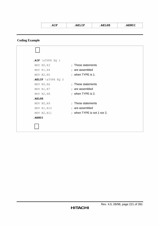
.AIF .AELIF .AELSE .AENDI
Rev. 4.0, 09/98, page 221 of 391
Coding Example
∼.AIF \&TYPE EQ 1
MOV R0,R3 ; These statements
MOV R1,R4 ; are assembled
MOV R2,R5 ; when TYPE is 1.
.AELIF \&TYPE EQ 2
MOV R0,R6 ; These statements
MOV R1,R7 ; are assembled
MOV R2,R8 ; when TYPE is 2.
.AELSE
MOV R0,R9 ; These statements
MOV R1,R10 ; are assembled
MOV R2,R11 ; when TYPE is not 1 nor 2.
.AENDI
∼
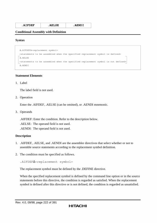
Rev. 4.0, 09/98, page 222 of 391
.AIFDEF .AELSE .AENDI
Conditional Assembly with Definition
Syntax
.AIFDEF <replacement symbol>
<statements to be assembled when the specified replacement symbol is defined>
.AELSE
<statements to be assembled when the specified replacement symbol is not defined>
.AENDI
Statement Elements
1. Label
The label field is not used.
2. Operation
Enter the .AIFDEF, .AELSE (can be omitted), or .AENDI mnemonic.
3. Operands
.AIFDEF: Enter the condition. Refer to the description below.
.AELSE: The operand field is not used.
.AENDI: The operand field is not used.
Description
1. .AIFDEF, .AELSE, and .AENDI are the assembler directives that select whether or not toassemble source statements according to the replacement symbol definition.
2. The condition must be specified as follows.
.AIFDEF ∆<replacement symbol>
The replacement symbol must be defined by the .DEFINE directive.
When the specified replacement symbol is defined by the command line option or in the sourcestatements before this directive, the condition is regarded as satisfied. When the replacementsymbol is defined after this directive or is not defined, the condition is regarded as unsatisfied.
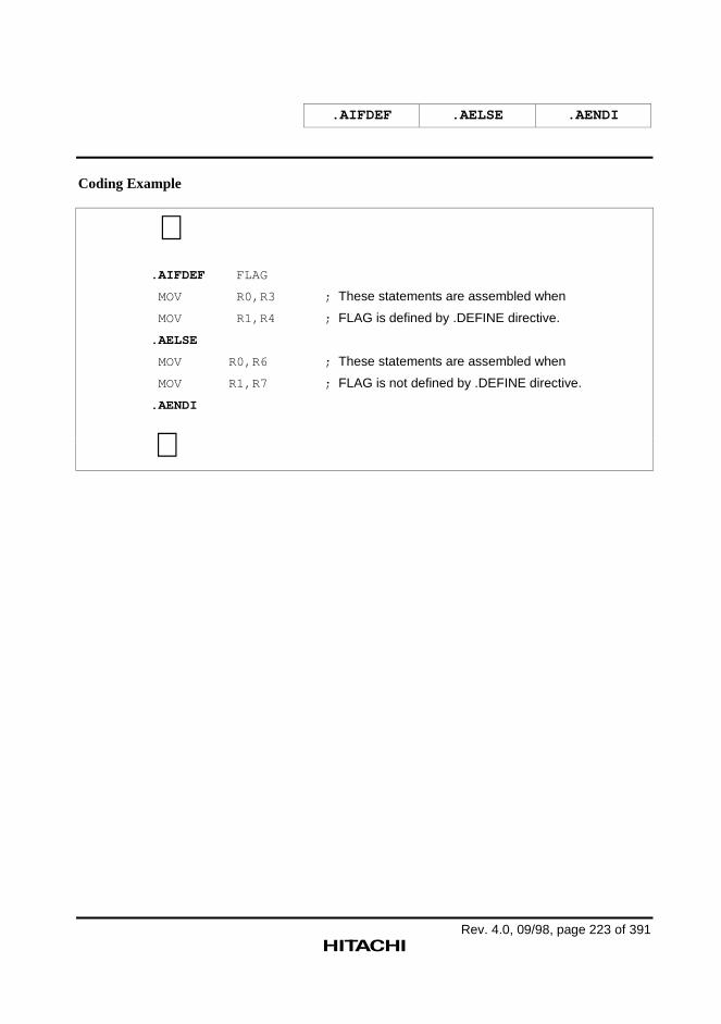
.AIFDEF .AELSE .AENDI
Rev. 4.0, 09/98, page 223 of 391
Coding Example
∼.AIFDEF FLAG
MOV R0,R3 ; These statements are assembled when
MOV R1,R4 ; FLAG is defined by .DEFINE directive.
.AELSE
MOV R0,R6 ; These statements are assembled when
MOV R1,R7 ; FLAG is not defined by .DEFINE directive.
.AENDI
∼
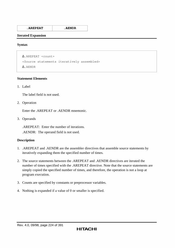
Rev. 4.0, 09/98, page 224 of 391
.AREPEAT .AENDR
Iterated Expansion
Syntax
∆.AREPEAT <count>
<Source statements iteratively assembled>
∆.AENDR
Statement Elements
1. Label
The label field is not used.
2. Operation
Enter the .AREPEAT or .AENDR mnemonic.
3. Operands
.AREPEAT: Enter the number of iterations.
.AENDR: The operand field is not used.
Description
1. .AREPEAT and .AENDR are the assembler directives that assemble source statements byiteratively expanding them the specified number of times.
2. The source statements between the .AREPEAT and .AENDR directives are iterated thenumber of times specified with the .AREPEAT directive. Note that the source statements aresimply copied the specified number of times, and therefore, the operation is not a loop atprogram execution.
3. Counts are specified by constants or preprocessor variables.
4. Nothing is expanded if a value of 0 or smaller is specified.
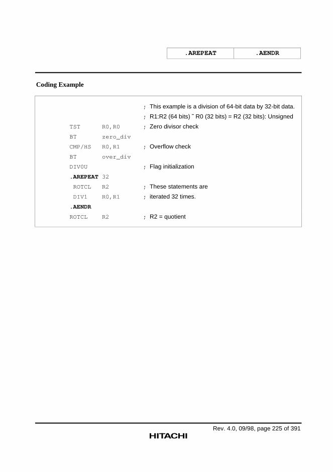
.AREPEAT .AENDR
Rev. 4.0, 09/98, page 225 of 391
Coding Example
; This example is a division of 64-bit data by 32-bit data.
; R1:R2 (64 bits) ˜ R0 (32 bits) = R2 (32 bits): Unsigned
TST R0,R0 ; Zero divisor check
BT zero_div
CMP/HS R0,R1 ; Overflow check
BT over_div
DIV0U ; Flag initialization
.AREPEAT 32
ROTCL R2 ; These statements are
DIV1 R0,R1 ; iterated 32 times.
.AENDR
ROTCL R2 ; R2 = quotient
Rev. 4.0, 09/98, page 226 of 391
.AWHILE .AENDW
Conditional Iterated Expansion
Syntax
∆.AWHILE∆<term1> ∆<relational operator> ∆<term2> <Source statements iteratively assembled> ∆.AENDW
Statement Elements
1. Label
The label field is not used.
2. Operation
Enter the .AWHILE or .AENDW mnemonic.
3. Operands
.AWHILE: Enter the condition to iteratively expand source statements.
.AENDW: The operand field is not used.
Description
1. .AWHILE and .AENDW are the assembler directives that assemble source statements byiteratively expanding them while the specified condition is satisfied.
2. The source statements between the .AWHILE and .AENDW directives are iterated while thecondition specified with the .AWHILE directive is satisfied. Note that the source statementsare simply copied iteratively, and therefore, the operation is not a loop at program execution.
3. The condition must be specified as follows:
.AWHILE∆<term1> ∆<relational operator> ∆<term2>
Terms are specified with numeric values or character strings. However, when a numeric valueand a character string are compared, the condition always fails.
.AWHILE .AENDW
Rev. 4.0, 09/98, page 227 of 391
Numeric values are specified by constants or preprocessor variables.
Character strings are specified by characters or preprocessor variables enclosed with doublequotation marks ("). To specify a double quotation mark in a character string, enter two doublequotation marks (" ") in succession.
Conditional iterated expansion terminates when the condition finally fails.
CAUTION!
If a condition which never fails is specified, source statements are iteratively expanded for65,535 times or until the maximum count of statement expansion specified by the .ALIMITdirective is reached. Accordingly, the condition for this directive must be carefully specified.
4. The following relational operators can be used:
EQ: term1 = term2
NE: term1 ≠ term2
GT: term1 > term2
LT: term1 < term2
GE: term1 ≥ term2
LE: term1 ≤ term2
Note: Numeric values are handled as 32-bit signed integers. For character strings, only EQ andNE conditions can be used.
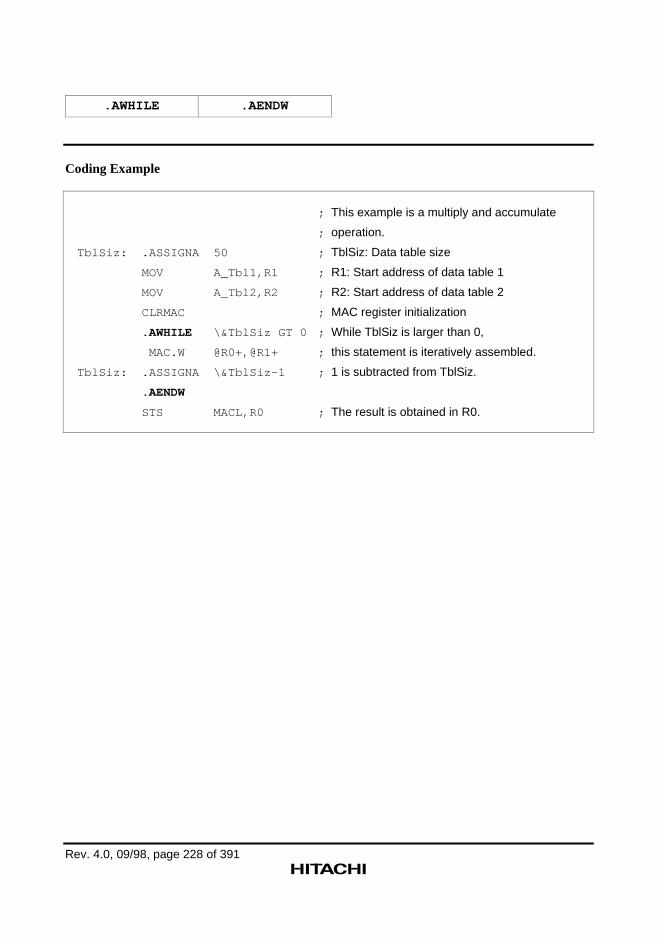
.AWHILE .AENDW
Rev. 4.0, 09/98, page 228 of 391
Coding Example
; This example is a multiply and accumulate
; operation.
TblSiz: .ASSIGNA 50 ; TblSiz: Data table size
MOV A_Tbl1,R1 ; R1: Start address of data table 1
MOV A_Tbl2,R2 ; R2: Start address of data table 2
CLRMAC ; MAC register initialization
.AWHILE \&TblSiz GT 0 ; While TblSiz is larger than 0,
MAC.W @R0+,@R1+ ; this statement is iteratively assembled.
TblSiz: .ASSIGNA \&TblSiz-1 ; 1 is subtracted from TblSiz.
.AENDW
STS MACL,R0 ; The result is obtained in R0.
Rev. 4.0, 09/98, page 229 of 391
.AERROR
Error Generation During Preprocessor Expansion
Syntax
∆.AERROR
Statement Elements
1. Label
The label field is not used.
2. Operation
Enter the .AERROR mnemonic.
3. Operands
The operand field is not used.
Description
1. When the .AERROR directive is assembled, error 667 is generated and the assembler isterminated with an error.
2. The .AERROR directive can be used to check values such as preprocessor variables.
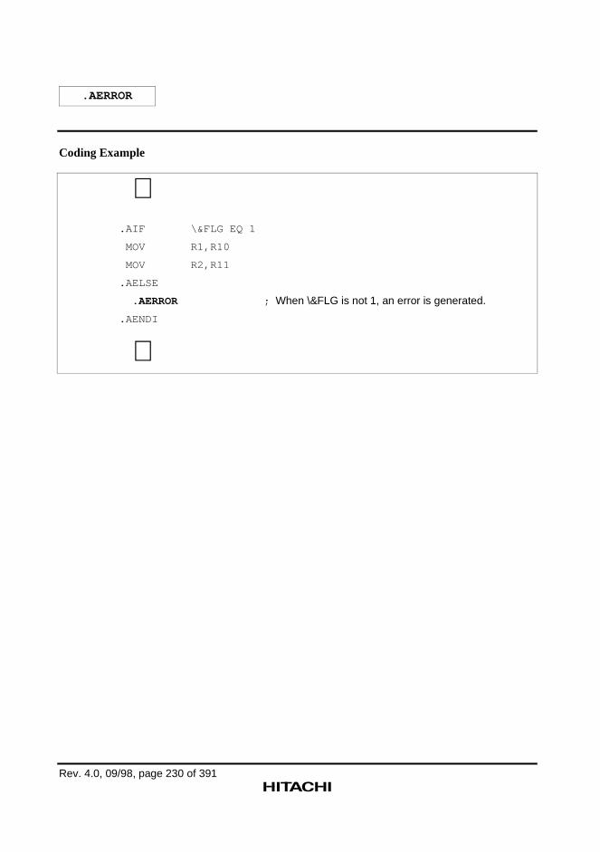
.AERROR
Rev. 4.0, 09/98, page 230 of 391
Coding Example
∼.AIF \&FLG EQ 1
MOV R1,R10
MOV R2,R11
.AELSE
.AERROR ; When \&FLG is not 1, an error is generated.
.AENDI
∼
Rev. 4.0, 09/98, page 231 of 391
.EXITM
Expansion Termination
Syntax
∆.EXITM
Statement Elements
1. Label
The label field is not used.
2. Operation
Enter the .EXITM mnemonic.
3. Operands
The operand field is not used.
Description
1. .EXITM is the assembler directive that terminates an iterated expansion (.AREPEAT to.AENDR) or a conditional iterated expansion (.AWHILE to .AENDW).
2. Each expansion is terminated when this directive appears.
3. This directive is also used to exit from macro expansions. The location of this directive mustbe specified carefully when macro instructions and iterated expansion are combined.
Reference: Macro expansion
→ Programmer's Guide, 8.2, "Macro Function Directives"
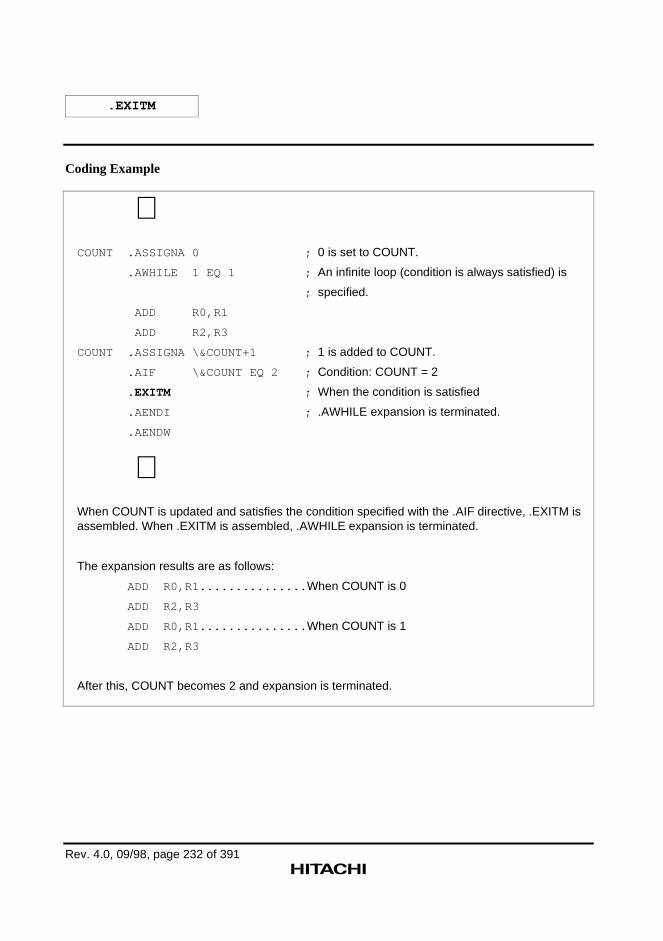
.EXITM
Rev. 4.0, 09/98, page 232 of 391
Coding Example
∼COUNT .ASSIGNA 0 ; 0 is set to COUNT.
.AWHILE 1 EQ 1 ; An infinite loop (condition is always satisfied) is
; specified.
ADD R0,R1
ADD R2,R3
COUNT .ASSIGNA \&COUNT+1 ; 1 is added to COUNT.
.AIF \&COUNT EQ 2 ; Condition: COUNT = 2
.EXITM ; When the condition is satisfied
.AENDI ; .AWHILE expansion is terminated.
.AENDW
∼When COUNT is updated and satisfies the condition specified with the .AIF directive, .EXITM isassembled. When .EXITM is assembled, .AWHILE expansion is terminated.
The expansion results are as follows:
ADD R0,R1............... When COUNT is 0
ADD R2,R3
ADD R0,R1............... When COUNT is 1
ADD R2,R3
After this, COUNT becomes 2 and expansion is terminated.
Rev. 4.0, 09/98, page 233 of 391
.ALIMIT
Maximum Count Specification for .AWHILE Expansion in Preprocessor
Syntax
∆.ALIMIT <count>
Statement Elements
1. Label
The label field is not used.
2. Operation
Enter the .ALIMIT mnemonic.
3. Operands
Enter the maximum count of statement expansion.
Description
1. During conditional iterated (.AWHILE to .AENDW) expansion, if the statement expansioncount exceeds the maximum value specified by the .ALIMIT directive, warning 854 isgenerated and the expansion is terminated.
2. If the .ALIMIT directive is not specified, the maximum count is 65,535.
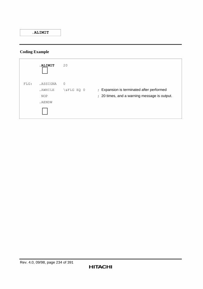
.ALIMIT
Rev. 4.0, 09/98, page 234 of 391
Coding Example
.ALIMIT 20
∼FLG: .ASSIGNA 0
.AWHILE \&FLG EQ 0 ; Expansion is terminated after performed
NOP ; 20 times, and a warning message is output.
.AENDW
∼
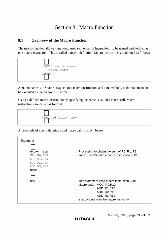
Rev. 4.0, 09/98, page 235 of 391
Section 8 Macro Function
8.1 Overview of the Macro Function
The macro function allows commonly used sequences of instructions to be named and defined asone macro instruction. This is called a macro definition. Macro instructions are defined as follows:
∼.MACRO <macro name> <macro body>.ENDM
∼A macro name is the name assigned to a macro instruction, and a macro body is the statements tobe executed as the macro instruction.
Using a defined macro instruction by specifying the name is called a macro call. Macroinstructions are called as follows:
∼<defined macro name> ∼
An example of macro definition and macro call is shown below.
Example:
∼.MACRO SUM ; Processing to obtain the sum of R0, R1, R2, MOV R0,R10 ; and R3 is defined as macro instruction SUM. ADD R1,R10 ADD R2,R10 ADD R3,R10.ENDM ∼ SUM ; This statement calls macro instruction SUM.
; Macro body MOV R0,R10; ADD R1,R10; ADD R2,R10; ADD R3,R10; is expanded from the macro instruction.
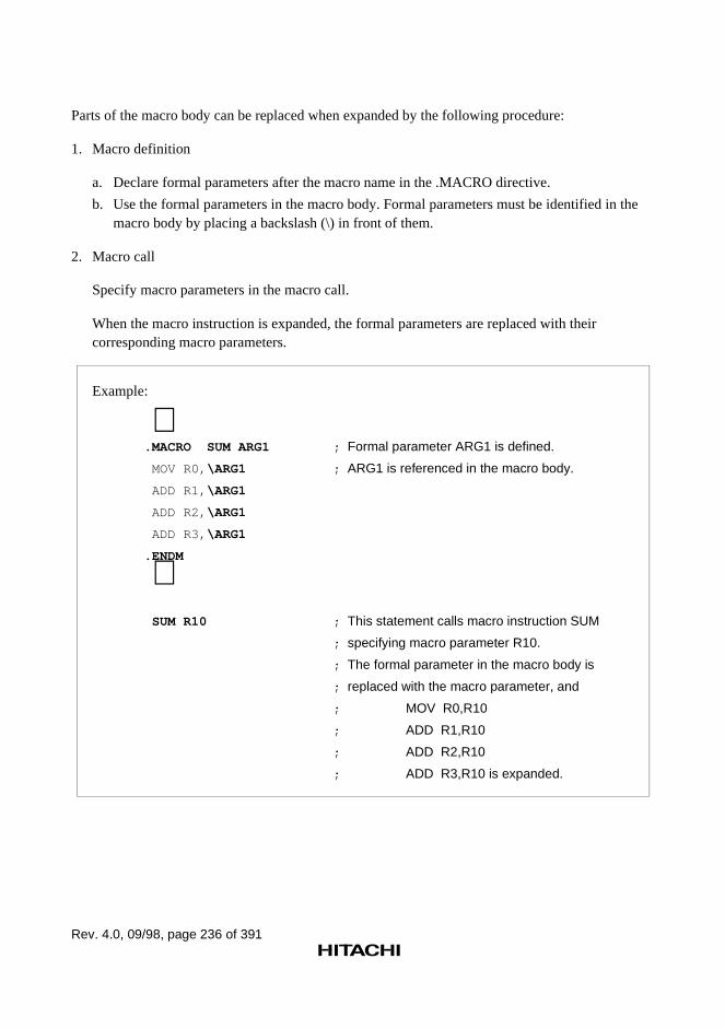
Rev. 4.0, 09/98, page 236 of 391
Parts of the macro body can be replaced when expanded by the following procedure:
1. Macro definition
a. Declare formal parameters after the macro name in the .MACRO directive.
b. Use the formal parameters in the macro body. Formal parameters must be identified in themacro body by placing a backslash (\) in front of them.
2. Macro call
Specify macro parameters in the macro call.
When the macro instruction is expanded, the formal parameters are replaced with theircorresponding macro parameters.
Example:
∼.MACRO SUM ARG1 ; Formal parameter ARG1 is defined.
MOV R0, \ARG1 ; ARG1 is referenced in the macro body.
ADD R1, \ARG1
ADD R2, \ARG1
ADD R3, \ARG1
.ENDM
∼ SUM R10 ; This statement calls macro instruction SUM
; specifying macro parameter R10.
; The formal parameter in the macro body is
; replaced with the macro parameter, and
; MOV R0,R10
; ADD R1,R10
; ADD R2,R10
; ADD R3,R10 is expanded.
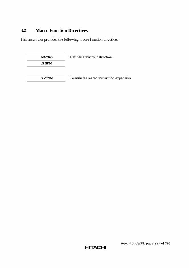
Rev. 4.0, 09/98, page 237 of 391
8.2 Macro Function Directives
This assembler provides the following macro function directives.
.MACRO Defines a macro instruction.
.ENDM
.EXITM Terminates macro instruction expansion.
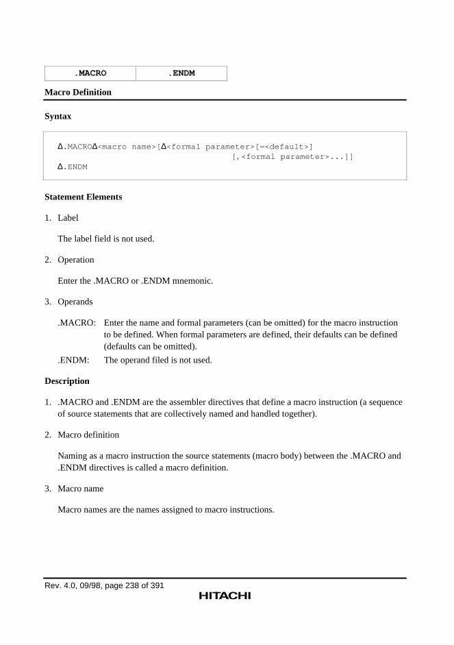
Rev. 4.0, 09/98, page 238 of 391
.MACRO .ENDM
Macro Definition
Syntax
∆.MACRO∆<macro name>[ ∆<formal parameter>[=<default>][,<formal parameter>...]]
∆.ENDM
Statement Elements
1. Label
The label field is not used.
2. Operation
Enter the .MACRO or .ENDM mnemonic.
3. Operands
.MACRO: Enter the name and formal parameters (can be omitted) for the macro instructionto be defined. When formal parameters are defined, their defaults can be defined(defaults can be omitted).
.ENDM: The operand filed is not used.
Description
1. .MACRO and .ENDM are the assembler directives that define a macro instruction (a sequenceof source statements that are collectively named and handled together).
2. Macro definition
Naming as a macro instruction the source statements (macro body) between the .MACRO and.ENDM directives is called a macro definition.
3. Macro name
Macro names are the names assigned to macro instructions.
.MACRO .ENDM
Rev. 4.0, 09/98, page 239 of 391
4. Formal parameters
Formal parameters are specified so that parts of the macro body can be replaced by specificparameters at expansion time. Formal parameters are replaced with the character strings(macro parameters) specified at macro expansion (macro call).
— Formal parameter syntax
The syntax for formal parameters is the same as that for symbols. A formal parameter canbe defined with up to 32 characters, and uppercase and lowercase letters are distinguished.
— Formal parameter reference
Formal parameters are used (referenced) at the part to be replaced in the macro body.
The syntax of formal parameter reference in macro bodies is as follows:
\<formal parameter name>['] *
To clearly distinguish the formal parameter name from the rest of the source statement, anapostrophe (') can be added.
Note: When using a Japanese environment, use ¥ instead of \ .
5. Formal parameter defaults
Defaults for formal parameters can be specified in macro definitions. The default specifies thecharacter string to replace the formal parameter when the corresponding macro parameter isomitted in a macro call.
The default must be enclosed with double quotation marks (") or angle brackets (<>) if any ofthe following characters are included in the default.
— Space
— Tab
— Comma (,)
— Semicolon (;)
— Double quotation marks (")
— Angle brackets (< >)
The assembler inserts defaults at macro expansion by removing the double quotation marks orangle brackets that enclose the character strings.
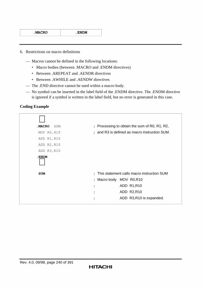
.MACRO .ENDM
Rev. 4.0, 09/98, page 240 of 391
6. Restrictions on macro definitions
— Macros cannot be defined in the following locations:
• Macro bodies (between .MACRO and .ENDM directives)
• Between .AREPEAT and .AENDR directives
• Between .AWHILE and .AENDW directives
— The .END directive cannot be used within a macro body.
— No symbol can be inserted in the label field of the .ENDM directive. The .ENDM directiveis ignored if a symbol is written in the label field, but no error is generated in this case.
Coding Example
∼.MACRO SUM ; Processing to obtain the sum of R0, R1, R2,
MOV R0,R10 ; and R3 is defined as macro instruction SUM.
ADD R1,R10
ADD R2,R10
ADD R3,R10
.ENDM
∼ SUM ; This statement calls macro instruction SUM
; Macro body MOV R0,R10
; ADD R1,R10
; ADD R2,R10
; ADD R3,R10 is expanded.
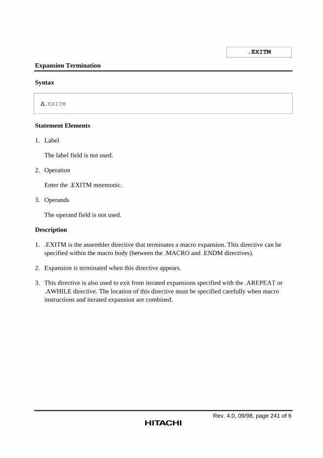
Rev. 4.0, 09/98, page 241 of 6
.EXITM
Expansion Termination
Syntax
∆.EXITM
Statement Elements
1. Label
The label field is not used.
2. Operation
Enter the .EXITM mnemonic.
3. Operands
The operand field is not used.
Description
1. .EXITM is the assembler directive that terminates a macro expansion. This directive can bespecified within the macro body (between the .MACRO and .ENDM directives).
2. Expansion is terminated when this directive appears.
3. This directive is also used to exit from iterated expansions specified with the .AREPEAT or.AWHILE directive. The location of this directive must be specified carefully when macroinstructions and iterated expansion are combined.
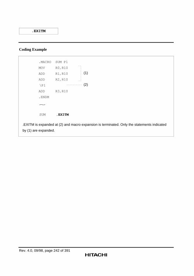
.EXITM
Rev. 4.0, 09/98, page 242 of 391
Coding Example
.MACRO SUM P1
MOV R0,R10
ADD R1,R10
ADD R2,R10
\P1
ADD R3,R10
.ENDM
SUM .EXITM
.EXITM is expanded at (2) and macro expansion is terminated. Only the statements indicated
by (1) are expanded.
(1)
(2)
~
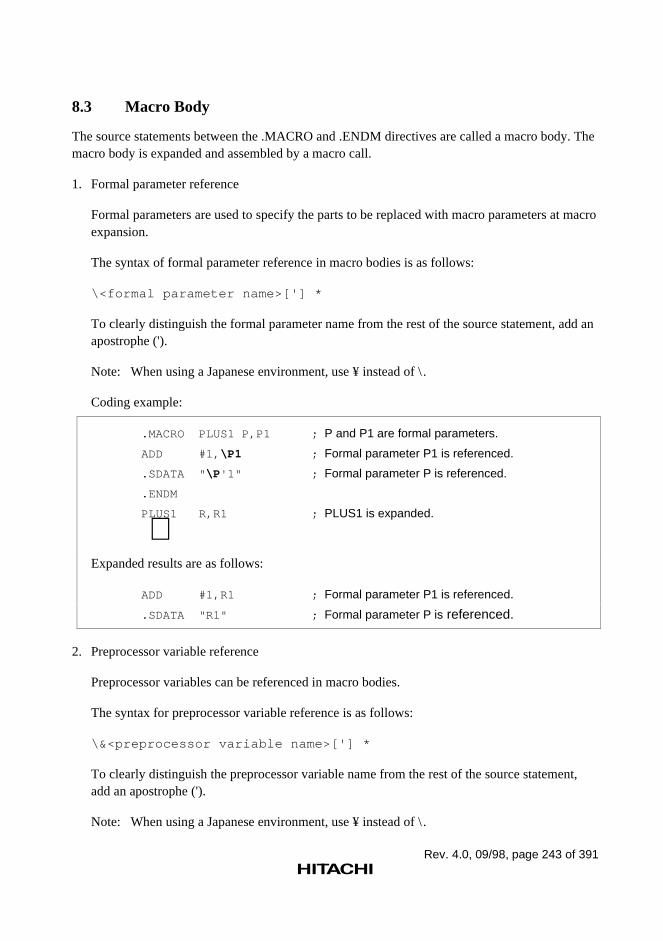
Rev. 4.0, 09/98, page 243 of 391
8.3 Macro Body
The source statements between the .MACRO and .ENDM directives are called a macro body. Themacro body is expanded and assembled by a macro call.
1. Formal parameter reference
Formal parameters are used to specify the parts to be replaced with macro parameters at macroexpansion.
The syntax of formal parameter reference in macro bodies is as follows:
\<formal parameter name>['] *
To clearly distinguish the formal parameter name from the rest of the source statement, add anapostrophe (').
Note: When using a Japanese environment, use ¥ instead of \ .
Coding example:
.MACRO PLUS1 P,P1 ; P and P1 are formal parameters.
ADD #1, \P1 ; Formal parameter P1 is referenced.
.SDATA " \P '1" ; Formal parameter P is referenced.
.ENDM
PLUS1 R,R1 ; PLUS1 is expanded.
∼Expanded results are as follows:
ADD #1,R1 ; Formal parameter P1 is referenced.
.SDATA "R1" ; Formal parameter P is referenced.
2. Preprocessor variable reference
Preprocessor variables can be referenced in macro bodies.
The syntax for preprocessor variable reference is as follows:
\&<preprocessor variable name>['] *
To clearly distinguish the preprocessor variable name from the rest of the source statement,add an apostrophe (').
Note: When using a Japanese environment, use ¥ instead of \ .
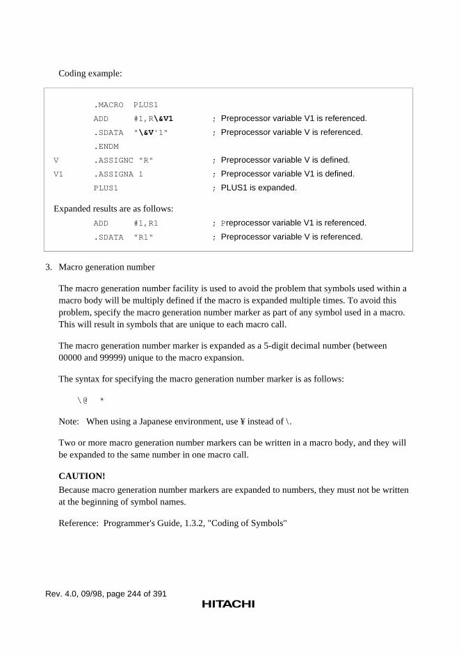
Rev. 4.0, 09/98, page 244 of 391
Coding example:
.MACRO PLUS1
ADD #1,R \&V1 ; Preprocessor variable V1 is referenced.
.SDATA " \&V '1" ; Preprocessor variable V is referenced.
.ENDM
V .ASSIGNC "R" ; Preprocessor variable V is defined.
V1 .ASSIGNA 1 ; Preprocessor variable V1 is defined.
PLUS1 ; PLUS1 is expanded.
Expanded results are as follows:
ADD #1,R1 ; P reprocessor variable V1 is referenced.
.SDATA "R1" ; Preprocessor variable V is referenced.
3. Macro generation number
The macro generation number facility is used to avoid the problem that symbols used within amacro body will be multiply defined if the macro is expanded multiple times. To avoid thisproblem, specify the macro generation number marker as part of any symbol used in a macro.This will result in symbols that are unique to each macro call.
The macro generation number marker is expanded as a 5-digit decimal number (between00000 and 99999) unique to the macro expansion.
The syntax for specifying the macro generation number marker is as follows:
\@ *
Note: When using a Japanese environment, use ¥ instead of \ .
Two or more macro generation number markers can be written in a macro body, and they willbe expanded to the same number in one macro call.
CAUTION!
Because macro generation number markers are expanded to numbers, they must not be writtenat the beginning of symbol names.
Reference: Programmer's Guide, 1.3.2, "Coding of Symbols"
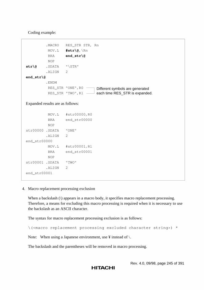
Rev. 4.0, 09/98, page 245 of 391
Coding example:
.MACRO RES_STR STR, Rn
MOV.L #str\@ ,\Rn
BRA end_str\@
NOP
str\@ .SDATA "\STR"
.ALIGN 2
end_str\@
.ENDM
RES_STR "ONE",R0
RES_STR "TWO",R1
Expanded results are as follows:
MOV.L #str00000,R0
BRA end_str00000
NOP
str00000 .SDATA "ONE"
.ALIGN 2
end_str00000
MOV.L #str00001,R1
BRA end_str00001
NOP
str00001 .SDATA "TWO"
.ALIGN 2
end_str00001
Different symbols are generated each time RES_STR is expanded.
4. Macro replacement processing exclusion
When a backslash (\) appears in a macro body, it specifies macro replacement processing.Therefore, a means for excluding this macro processing is required when it is necessary to usethe backslash as an ASCII character.
The syntax for macro replacement processing exclusion is as follows:
\(<macro replacement processing excluded character string>) *
Note: When using a Japanese environment, use ¥ instead of \ .
The backslash and the parentheses will be removed in macro processing.
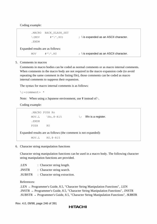
Rev. 4.0, 09/98, page 246 of 391
Coding example:
.MACRO BACK_SLASH_SET
\(MOV #"\",R0) ; \ is expanded as an ASCII character.
.ENDM
Expanded results are as follows:
MOV #"\",R0 ; \ is expanded as an ASCII character.
5. Comments in macros
Comments in macro bodies can be coded as normal comments or as macro internal comments.When comments in the macro body are not required in the macro expansion code (to avoidrepeating the same comment in the listing file), those comments can be coded as macrointernal comments to suppress their expansion.
The syntax for macro internal comments is as follows:
\;<comment> *
Note: When using a Japanese environment, use ¥ instead of \ .
Coding example:
.MACRO PUSH Rn
MOV.L \Rn,@-R15 \; \Rn is a register.
.ENDM
PUSH R0
Expanded results are as follows (the comment is not expanded):
MOV.L R0,@-R15
6. Character string manipulation functions
Character string manipulation functions can be used in a macro body. The following characterstring manipulation functions are provided.
.LEN : Character string length.
.INSTR : Character string search.
.SUBSTR : Character string extraction.
References:
.LEN → Programmer's Guide, 8.5, "Character String Manipulation Functions", .LEN
.INSTR → Programmer's Guide, 8.5, "Character String Manipulation Functions", .INSTR
.SUBSTR → Programmer's Guide, 8.5, "Character String Manipulation Functions", .SUBSTR
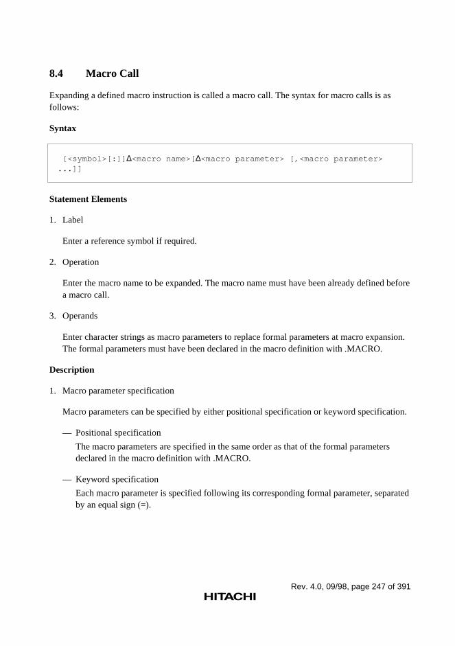
Rev. 4.0, 09/98, page 247 of 391
8.4 Macro Call
Expanding a defined macro instruction is called a macro call. The syntax for macro calls is asfollows:
Syntax
[<symbol>[:]] ∆<macro name>[ ∆<macro parameter> [,<macro parameter>...]]
Statement Elements
1. Label
Enter a reference symbol if required.
2. Operation
Enter the macro name to be expanded. The macro name must have been already defined beforea macro call.
3. Operands
Enter character strings as macro parameters to replace formal parameters at macro expansion.The formal parameters must have been declared in the macro definition with .MACRO.
Description
1. Macro parameter specification
Macro parameters can be specified by either positional specification or keyword specification.
— Positional specification
The macro parameters are specified in the same order as that of the formal parametersdeclared in the macro definition with .MACRO.
— Keyword specification
Each macro parameter is specified following its corresponding formal parameter, separatedby an equal sign (=).
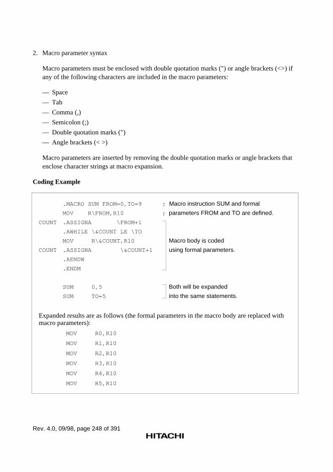
Rev. 4.0, 09/98, page 248 of 391
2. Macro parameter syntax
Macro parameters must be enclosed with double quotation marks (") or angle brackets (<>) ifany of the following characters are included in the macro parameters:
— Space
— Tab
— Comma (,)
— Semicolon (;)
— Double quotation marks (")
— Angle brackets (< >)
Macro parameters are inserted by removing the double quotation marks or angle brackets thatenclose character strings at macro expansion.
Coding Example
.MACRO SUM FROM=0,TO=9
MOV R\FROM,R10
COUNT .ASSIGNA \FROM+1
.AWHILE \&COUNT LE \TO
MOV R\&COUNT,R10
COUNT .ASSIGNA \&COUNT+1
.AENDW
.ENDM
SUM 0,5
SUM TO=5
; Macro instruction SUM and formal
; parameters FROM and TO are defined.
Macro body is coded
using formal parameters.
Both will be expanded
into the same statements.
Expanded results are as follows (the formal parameters in the macro body are replaced withmacro parameters):
MOV R0,R10
MOV R1,R10
MOV R2,R10
MOV R3,R10
MOV R4,R10
MOV R5,R10
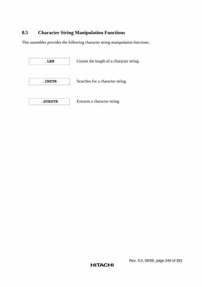
Rev. 4.0, 09/98, page 249 of 391
8.5 Character String Manipulation Functions
This assembler provides the following character string manipulation functions.
.LEN Counts the length of a character string.
.INSTR Searches for a character string.
.SUBSTR Extracts a character string.
Rev. 4.0, 09/98, page 250 of 391
.LEN
Character String Length Count
Syntax
.LEN[ ∆]("<character string>")
Description
1. .LEN counts the number of characters in a character string and replaces itself with the numberof characters in decimal with no radix.
2. Character strings are specified by enclosing the desired characters with double quotation marks("). To specify a double quotation mark in a character string, enter two double quotation marksin succession.
3. Macro formal parameters and preprocessor variables can be specified in the character string asshown below.
.LEN("\<formal parameter>")
.LEN("\&<preprocessor variable>") *
Note: When using a Japanese environment, use ¥ instead of \ .
4. This function can only be used within a macro body (between .MACRO and .ENDMdirectives).
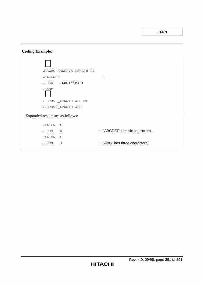
.LEN
Rev. 4.0, 09/98, page 251 of 391
Coding Example:
∼.MACRO RESERVE_LENGTH P1
.ALIGN 4 .
.SRES .LEN("\P1")
.ENDM
∼RESERVE_LENGTH ABCDEF
RESERVE_LENGTH ABC
Expanded results are as follows:
.ALIGN 4
.SRES 6 ; "ABCDEF" has six characters.
.ALIGN 4
.SRES 3 ; "ABC" has three characters.
Rev. 4.0, 09/98, page 252 of 391
.INSTR
Character String Search
Syntax
.INSTR[ ∆]("<character string 1>","<character string 2>"[,<start position>])
Description
1. .INSTR searches character string 1 for character string 2, and replaces itself with the numericalvalue of the position of the found string (with 0 indicating the start of the string) in decimalwith no radix. .INSTR is replaced with –1 if character string 2 does not appear in characterstring 1.
2. Character strings are specified by enclosing the desired characters with double quotation marks("). To specify a double quotation mark in a character string, enter two double quotation marksin succession.
3. The <start position> parameter specifies the search start position as a numerical value, with 0indicating the start of character string 1. Zero is used as default when this parameter is omitted.
4. Macro formal parameters and preprocessor variables can be specified in the character stringsand as the start position as shown below.
.INSTR("\<formal parameter>", ...)
.INSTR("\&<preprocessor variable>", ...) *
Note: When using a Japanese environment, use ¥ instead of \ .
5. This function can only be used within a macro body (between the .MACRO and .ENDMdirectives).
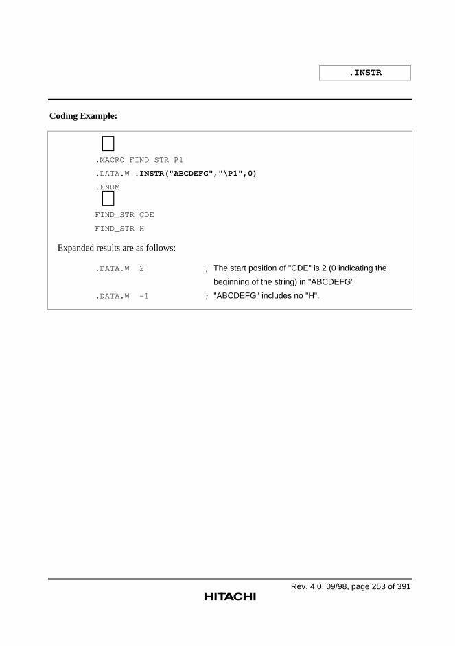
.INSTR
Rev. 4.0, 09/98, page 253 of 391
Coding Example:
∼.MACRO FIND_STR P1
.DATA.W .INSTR("ABCDEFG","\P1",0)
.ENDM
∼FIND_STR CDE
FIND_STR H
Expanded results are as follows:
.DATA.W 2 ; The start position of "CDE" is 2 (0 indicating the
beginning of the string) in "ABCDEFG"
.DATA.W -1 ; "ABCDEFG" includes no "H".
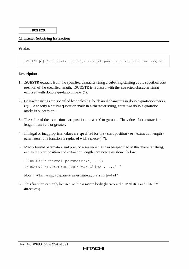
Rev. 4.0, 09/98, page 254 of 391
.SUBSTR
Character Substring Extraction
Syntax
.SUBSTR[ ∆]("<character string>",<start position>,<extraction length>)
Description
1. .SUBSTR extracts from the specified character string a substring starting at the specified startposition of the specified length. .SUBSTR is replaced with the extracted character stringenclosed with double quotation marks (").
2. Character strings are specified by enclosing the desired characters in double quotation marks("). To specify a double quotation mark in a character string, enter two double quotationmarks in succession.
3. The value of the extraction start position must be 0 or greater. The value of the extractionlength must be 1 or greater.
4. If illegal or inappropriate values are specified for the <start position> or <extraction length>parameters, this function is replaced with a space (" ").
5. Macro formal parameters and preprocessor variables can be specified in the character string,and as the start position and extraction length parameters as shown below.
.SUBSTR("\<formal parameter>", ...)
.SUBSTR("\&<preprocessor variable>", ...) *
Note: When using a Japanese environment, use ¥ instead of \ .
6. This function can only be used within a macro body (between the .MACRO and .ENDMdirectives).
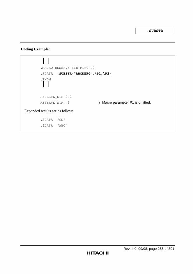
.SUBSTR
Rev. 4.0, 09/98, page 255 of 391
Coding Example:
∼.MACRO RESERVE_STR P1=0,P2
.SDATA .SUBSTR("ABCDEFG",\P1,\P2)
.ENDM
∼RESERVE_STR 2,2
RESERVE_STR ,3 ; Macro parameter P1 is omitted.
Expanded results are as follows:
.SDATA "CD"
.SDATA "ABC"
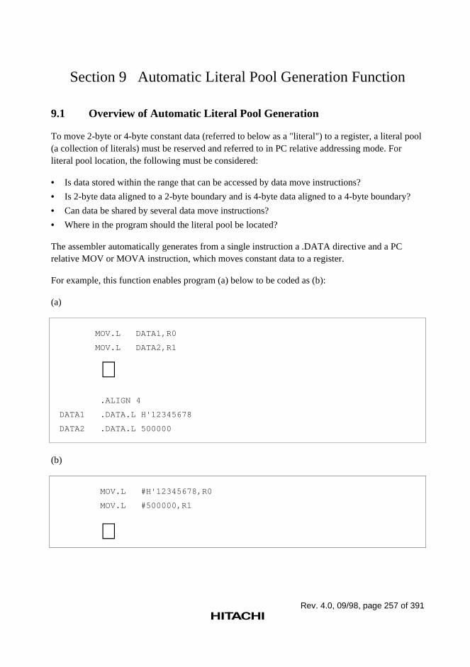
Rev. 4.0, 09/98, page 257 of 391
Section 9 Automatic Literal Pool Generation Function
9.1 Overview of Automatic Literal Pool Generation
To move 2-byte or 4-byte constant data (referred to below as a "literal") to a register, a literal pool(a collection of literals) must be reserved and referred to in PC relative addressing mode. Forliteral pool location, the following must be considered:
• Is data stored within the range that can be accessed by data move instructions?
• Is 2-byte data aligned to a 2-byte boundary and is 4-byte data aligned to a 4-byte boundary?
• Can data be shared by several data move instructions?
• Where in the program should the literal pool be located?
The assembler automatically generates from a single instruction a .DATA directive and a PCrelative MOV or MOVA instruction, which moves constant data to a register.
For example, this function enables program (a) below to be coded as (b):
(a)
MOV.L DATA1,R0
MOV.L DATA2,R1
∼ .ALIGN 4
DATA1 .DATA.L H'12345678
DATA2 .DATA.L 500000
(b)
MOV.L #H'12345678,R0
MOV.L #500000,R1
∼
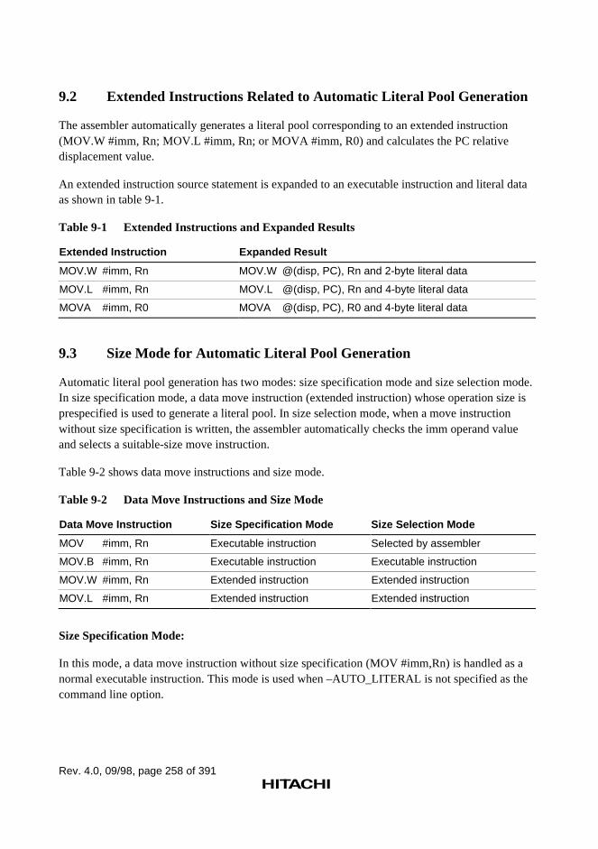
Rev. 4.0, 09/98, page 258 of 391
9.2 Extended Instructions Related to Automatic Literal Pool Generation
The assembler automatically generates a literal pool corresponding to an extended instruction(MOV.W #imm, Rn; MOV.L #imm, Rn; or MOVA #imm, R0) and calculates the PC relativedisplacement value.
An extended instruction source statement is expanded to an executable instruction and literal dataas shown in table 9-1.
Table 9-1 Extended Instructions and Expanded Results
Extended Instruction Expanded Result
MOV.W #imm, Rn MOV.W @(disp, PC), Rn and 2-byte literal data
MOV.L #imm, Rn MOV.L @(disp, PC), Rn and 4-byte literal data
MOVA #imm, R0 MOVA @(disp, PC), R0 and 4-byte literal data
9.3 Size Mode for Automatic Literal Pool Generation
Automatic literal pool generation has two modes: size specification mode and size selection mode.In size specification mode, a data move instruction (extended instruction) whose operation size isprespecified is used to generate a literal pool. In size selection mode, when a move instructionwithout size specification is written, the assembler automatically checks the imm operand valueand selects a suitable-size move instruction.
Table 9-2 shows data move instructions and size mode.
Table 9-2 Data Move Instructions and Size Mode
Data Move Instruction Size Specification Mode Size Selection Mode
MOV #imm, Rn Executable instruction Selected by assembler
MOV.B #imm, Rn Executable instruction Executable instruction
MOV.W #imm, Rn Extended instruction Extended instruction
MOV.L #imm, Rn Extended instruction Extended instruction
Size Specification Mode:
In this mode, a data move instruction without size specification (MOV #imm,Rn) is handled as anormal executable instruction. This mode is used when –AUTO_LITERAL is not specified as thecommand line option.
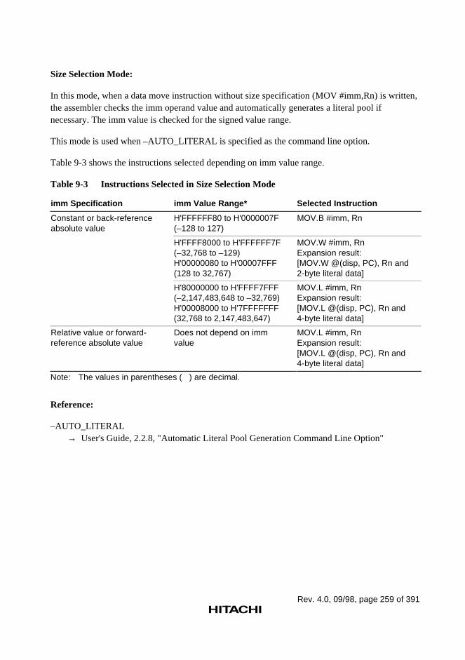
Rev. 4.0, 09/98, page 259 of 391
Size Selection Mode:
In this mode, when a data move instruction without size specification (MOV #imm,Rn) is written,the assembler checks the imm operand value and automatically generates a literal pool ifnecessary. The imm value is checked for the signed value range.
This mode is used when –AUTO_LITERAL is specified as the command line option.
Table 9-3 shows the instructions selected depending on imm value range.
Table 9-3 Instructions Selected in Size Selection Mode
imm Specification imm Value Range* Selected Instruction
Constant or back-referenceabsolute value
H'FFFFFF80 to H'0000007F(–128 to 127)
MOV.B #imm, Rn
H'FFFF8000 to H'FFFFFF7F(–32,768 to –129)H'00000080 to H'00007FFF(128 to 32,767)
MOV.W #imm, RnExpansion result:[MOV.W @(disp, PC), Rn and2-byte literal data]
H'80000000 to H'FFFF7FFF(–2,147,483,648 to –32,769)H'00008000 to H'7FFFFFFF(32,768 to 2,147,483,647)
MOV.L #imm, RnExpansion result:[MOV.L @(disp, PC), Rn and4-byte literal data]
Relative value or forward-reference absolute value
Does not depend on immvalue
MOV.L #imm, RnExpansion result:[MOV.L @(disp, PC), Rn and4-byte literal data]
Note: The values in parentheses ( ) are decimal.
Reference:
–AUTO_LITERAL→ User's Guide, 2.2.8, "Automatic Literal Pool Generation Command Line Option"
Rev. 4.0, 09/98, page 260 of 391
9.4 Literal Pool Output
The literal pool is output to one of the following locations:
• After an unconditional branch and its delay slot instruction
• Where a .POOL directive has been specified by the programmer
The assembler outputs the literal corresponding to an extended instruction to the nearest outputlocation following the extended instruction. The assembler gathers the literals to be output as aliteral pool.
CAUTION!
When a label is specified in a delay slot instruction, no literal pool will be output to the locationfollowing the delay slot.
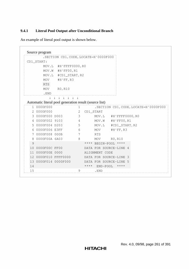
Rev. 4.0, 09/98, page 261 of 391
9.4.1 Literal Pool Output after Unconditional Branch
An example of literal pool output is shown below.
Source program .SECTION CD1,CODE,LOCATE=H'0000F000
CD1_START:
MOV.L #H'FFFF0000,R0
MOV.W #H'FF00,R1
MOV.L #CD1_START,R2
MOV #H'FF,R3
RTS
MOV R0,R10
.END
↓ ↓ ↓ ↓ ↓ ↓ ↓Automatic literal pool generation result (source list)
1 0000F000 1 .SECTION CD1,CODE,LOCATE=H'0000F000
2 0000F000 2 CD1_START
3 0000F000 D003 3 MOV.L #H'FFFF0000,R0
4 0000F002 9103 4 MOV.W #H'FF00,R1
5 0000F004 D203 5 MOV.L #CD1_START,R2
6 0000F006 E3FF 6 MOV #H'FF,R3
7 0000F008 000B 7 RTS
8 0000F00A 6A03 8 MOV R0,R10
9 **** BEGIN-POOL ****
10 0000F00C FF00 DATA FOR SOURCE-LINE 4
11 0000F00E 0000 ALIGNMENT CODE
12 0000F010 FFFF0000 DATA FOR SOURCE-LINE 3
13 0000F014 0000F000 DATA FOR SOURCE-LINE 5
14 **** END-POOL ****
15 9 .END
Rev. 4.0, 09/98, page 262 of 391
9.4.2 Literal Pool Output to the .POOL Location
If literal pool output location after unconditional branches is not available within the validdisplacement range (because the program has a small number of unconditional branches), theassembler outputs error 402. In this case, a .POOL directive must be specified within the validdisplacement range.
The valid displacement range is as follows:
• Word-size operation: 0 to 511 bytes
• Longword-size operation: 0 to 1023 bytes
When a literal pool is output to a .POOL location, a branch instruction is also inserted to jumpover the literal pool.
An example of literal pool output is shown on the following page.
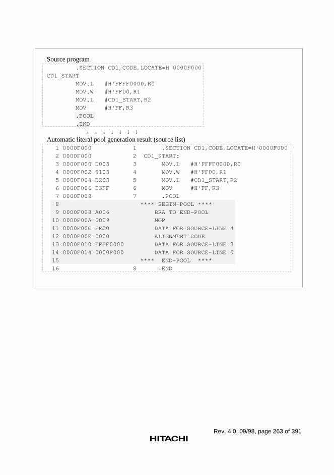
Rev. 4.0, 09/98, page 263 of 391
Source program .SECTION CD1,CODE,LOCATE=H'0000F000
CD1_START
MOV.L #H'FFFF0000,R0
MOV.W #H'FF00,R1
MOV.L #CD1_START,R2
MOV #H'FF,R3
.POOL
.END
↓ ↓ ↓ ↓ ↓ ↓ ↓Automatic literal pool generation result (source list)
1 0000F000 1 .SECTION CD1,CODE,LOCATE=H'0000F000
2 0000F000 2 CD1_START:
3 0000F000 D003 3 MOV.L #H'FFFF0000,R0
4 0000F002 9103 4 MOV.W #H'FF00,R1
5 0000F004 D203 5 MOV.L #CD1_START,R2
6 0000F006 E3FF 6 MOV #H'FF,R3
7 0000F008 7 .POOL
8 **** BEGIN-POOL ****
9 0000F008 A006 BRA TO END-POOL
10 0000F00A 0009 NOP
11 0000F00C FF00 DATA FOR SOURCE-LINE 4
12 0000F00E 0000 ALIGNMENT CODE
13 0000F010 FFFF0000 DATA FOR SOURCE-LINE 3
14 0000F014 0000F000 DATA FOR SOURCE-LINE 5
15 **** END-POOL ****
16 8 .END
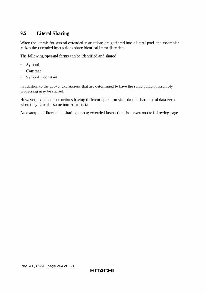
Rev. 4.0, 09/98, page 264 of 391
9.5 Literal Sharing
When the literals for several extended instructions are gathered into a literal pool, the assemblermakes the extended instructions share identical immediate data.
The following operand forms can be identified and shared:
• Symbol
• Constant
• Symbol ± constant
In addition to the above, expressions that are determined to have the same value at assemblyprocessing may be shared.
However, extended instructions having different operation sizes do not share literal data evenwhen they have the same immediate data.
An example of literal data sharing among extended instructions is shown on the following page.
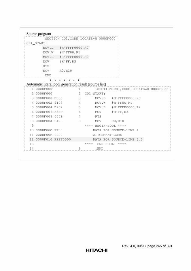
Rev. 4.0, 09/98, page 265 of 391
Source program .SECTION CD1,CODE,LOCATE=H'0000F000
CD1_START:
MOV.L #H'FFFF0000,R0
MOV.W #H'FF00,R1
MOV.L #H'FFFF0000,R2
MOV #H'FF,R3
RTS
MOV R0,R10
.END
↓ ↓ ↓ ↓ ↓ ↓ ↓Automatic literal pool generation result (source list)
1 0000F000 1 .SECTION CD1,CODE,LOCATE=H'0000F000
2 0000F000 2 CD1_START:
3 0000F000 D003 3 MOV.L #H'FFFF0000,R0
4 0000F002 9103 4 MOV.W #H'FF00,R1
5 0000F004 D202 5 MOV.L #H'FFFF0000,R2
6 0000F006 E3FF 6 MOV #H'FF,R3
7 0000F008 000B 7 RTS
8 0000F00A 6A03 8 MOV R0,R10
9 **** BEGIN-POOL ****
10 0000F00C FF00 DATA FOR SOURCE-LINE 4
11 0000F00E 0000 ALIGNMENT CODE
12 0000F010 FFFF0000 DATA FOR SOURCE-LINE 3,5
13 **** END-POOL ****
14 9 .END
Rev. 4.0, 09/98, page 266 of 391
9.6 Literal Pool Output Suppression
When a program has too many unconditional branches, the following problems may occur:
• Many small literal pools are output
• Literals are not shared
In these cases, suppress literal pool output as shown below.
∼<delayed branch instruction><delay slot instruction>.NOPOOL ∼
Example
Source program
CASE1: MOV.L #H'FFFF0000,R0 --------- Extended instruction 1 RTS NOP .NOPOOL --------- No literal pool is output hereCASE2: MOV.L #H'FFFF0000,R0 --------- Extended instruction 2 RTS NOP --------- Literal pool is output here
↓ ↓ ↓ ↓ ↓ ↓ ↓Automatic literal pool generation result (source list)
20 0000F000 20 CASE1:21 0000F000 D002 21 MOV.L #H'FFFF0000,R022 0000F002 000B 22 RTS23 0000F004 0009 23 NOP24 24 .NOPOOL25 0000F006 25 CASE2:26 0000F006 D001 26 MOV.L #H'FFFF0000,R027 0000F008 000B 27 RTS
28 0000F00A 0009 28 NOP29 **** BEGIN-POOL ****30 0000F00C FFFF0000 DATA FOR SOURCE-LINE 21,2631 **** END-POOL ****
~
~
~
~
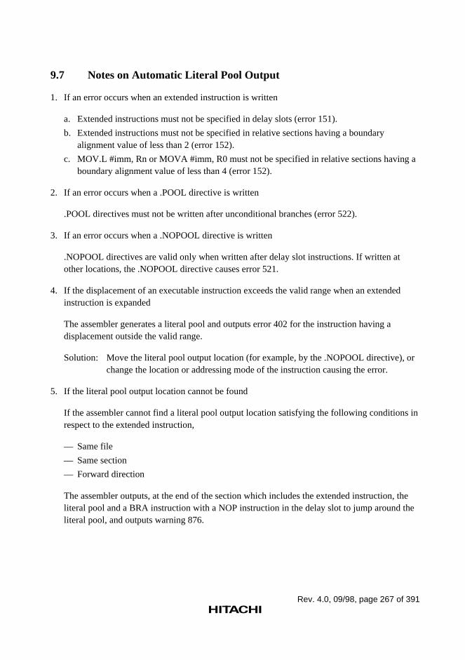
Rev. 4.0, 09/98, page 267 of 391
9.7 Notes on Automatic Literal Pool Output
1. If an error occurs when an extended instruction is written
a. Extended instructions must not be specified in delay slots (error 151).
b. Extended instructions must not be specified in relative sections having a boundaryalignment value of less than 2 (error 152).
c. MOV.L #imm, Rn or MOVA #imm, R0 must not be specified in relative sections having aboundary alignment value of less than 4 (error 152).
2. If an error occurs when a .POOL directive is written
.POOL directives must not be written after unconditional branches (error 522).
3. If an error occurs when a .NOPOOL directive is written
.NOPOOL directives are valid only when written after delay slot instructions. If written atother locations, the .NOPOOL directive causes error 521.
4. If the displacement of an executable instruction exceeds the valid range when an extendedinstruction is expanded
The assembler generates a literal pool and outputs error 402 for the instruction having adisplacement outside the valid range.
Solution: Move the literal pool output location (for example, by the .NOPOOL directive), orchange the location or addressing mode of the instruction causing the error.
5. If the literal pool output location cannot be found
If the assembler cannot find a literal pool output location satisfying the following conditions inrespect to the extended instruction,
— Same file
— Same section
— Forward direction
The assembler outputs, at the end of the section which includes the extended instruction, theliteral pool and a BRA instruction with a NOP instruction in the delay slot to jump around theliteral pool, and outputs warning 876.
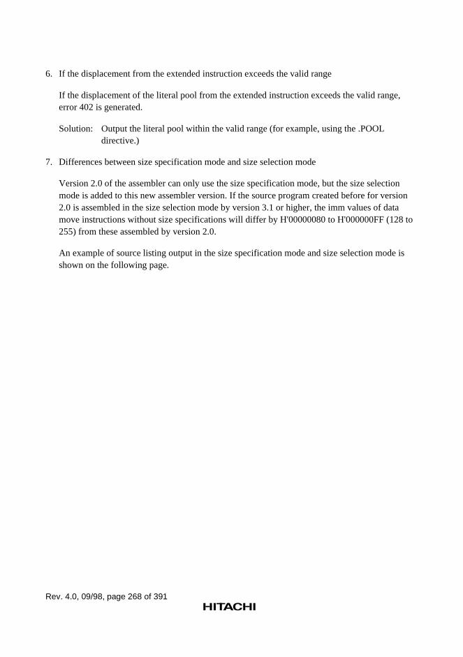
Rev. 4.0, 09/98, page 268 of 391
6. If the displacement from the extended instruction exceeds the valid range
If the displacement of the literal pool from the extended instruction exceeds the valid range,error 402 is generated.
Solution: Output the literal pool within the valid range (for example, using the .POOLdirective.)
7. Differences between size specification mode and size selection mode
Version 2.0 of the assembler can only use the size specification mode, but the size selectionmode is added to this new assembler version. If the source program created before for version2.0 is assembled in the size selection mode by version 3.1 or higher, the imm values of datamove instructions without size specifications will differ by H'00000080 to H'000000FF (128 to255) from these assembled by version 2.0.
An example of source listing output in the size specification mode and size selection mode isshown on the following page.
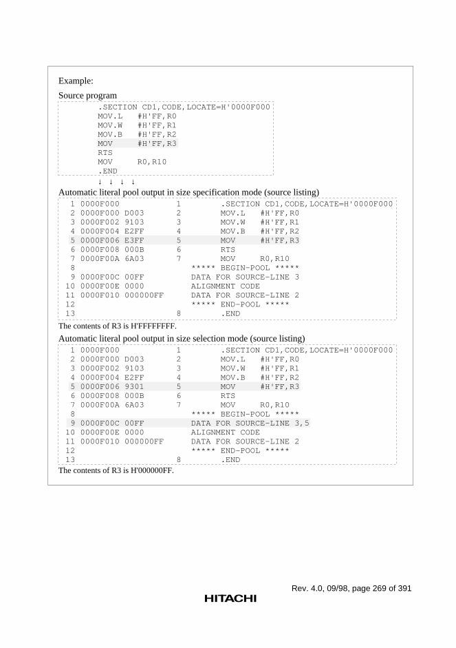
Rev. 4.0, 09/98, page 269 of 391
Source program .SECTION CD1,CODE,LOCATE=H'0000F000 MOV.L #H'FF,R0 MOV.W #H'FF,R1 MOV.B #H'FF,R2 MOV #H'FF,R3 RTS MOV R0,R10 .END
↓ ↓ ↓ ↓ Automatic literal pool output in size specification mode (source listing)
1 0000F000 1 .SECTION CD1,CODE,LOCATE=H'0000F000 2 0000F000 D003 2 MOV.L #H'FF,R0 3 0000F002 9103 3 MOV.W #H'FF,R1 4 0000F004 E2FF 4 MOV.B #H'FF,R2 5 0000F006 E3FF 5 MOV #H'FF,R3 6 0000F008 000B 6 RTS 7 0000F00A 6A03 7 MOV R0,R10 8 ***** BEGIN-POOL ***** 9 0000F00C 00FF DATA FOR SOURCE-LINE 310 0000F00E 0000 ALIGNMENT CODE11 0000F010 000000FF DATA FOR SOURCE-LINE 212 ***** END-POOL *****13 8 .END
The contents of R3 is H'FFFFFFFF.
Automatic literal pool output in size selection mode (source listing) 1 0000F000 1 .SECTION CD1,CODE,LOCATE=H'0000F000 2 0000F000 D003 2 MOV.L #H'FF,R0 3 0000F002 9103 3 MOV.W #H'FF,R1 4 0000F004 E2FF 4 MOV.B #H'FF,R2 5 0000F006 9301 5 MOV #H'FF,R3 6 0000F008 000B 6 RTS 7 0000F00A 6A03 7 MOV R0,R10 8 ***** BEGIN-POOL ***** 9 0000F00C 00FF DATA FOR SOURCE-LINE 3,510 0000F00E 0000 ALIGNMENT CODE11 0000F010 000000FF DATA FOR SOURCE-LINE 212 ***** END-POOL *****13 8 .END
The contents of R3 is H'000000FF.
Example:
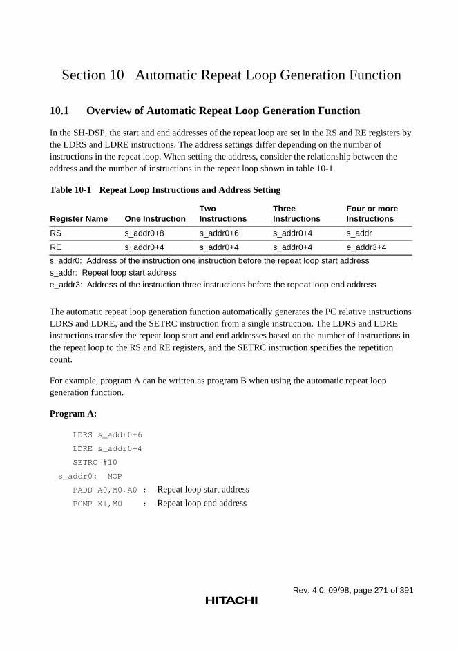
Rev. 4.0, 09/98, page 271 of 391
Section 10 Automatic Repeat Loop Generation Function
10.1 Overview of Automatic Repeat Loop Generation Function
In the SH-DSP, the start and end addresses of the repeat loop are set in the RS and RE registers bythe LDRS and LDRE instructions. The address settings differ depending on the number ofinstructions in the repeat loop. When setting the address, consider the relationship between theaddress and the number of instructions in the repeat loop shown in table 10-1.
Table 10-1 Repeat Loop Instructions and Address Setting
Register Name One InstructionTwoInstructions
ThreeInstructions
Four or moreInstructions
RS s_addr0+8 s_addr0+6 s_addr0+4 s_addr
RE s_addr0+4 s_addr0+4 s_addr0+4 e_addr3+4
s_addr0: Address of the instruction one instruction before the repeat loop start addresss_addr: Repeat loop start addresse_addr3: Address of the instruction three instructions before the repeat loop end address
The automatic repeat loop generation function automatically generates the PC relative instructionsLDRS and LDRE, and the SETRC instruction from a single instruction. The LDRS and LDREinstructions transfer the repeat loop start and end addresses based on the number of instructions inthe repeat loop to the RS and RE registers, and the SETRC instruction specifies the repetitioncount.
For example, program A can be written as program B when using the automatic repeat loopgeneration function.
Program A:
LDRS s_addr0+6
LDRE s_addr0+4
SETRC #10
s_addr0: NOP
PADD A0,M0,A0 ; Repeat loop start address
PCMP X1,M0 ; Repeat loop end address
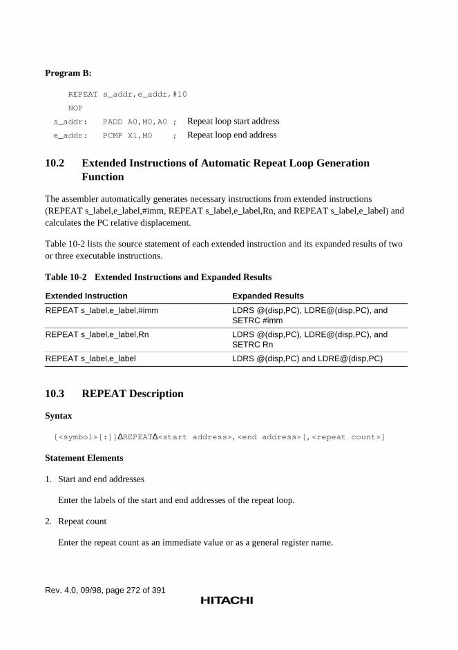
Rev. 4.0, 09/98, page 272 of 391
Program B:
REPEAT s_addr,e_addr,#10
NOP
s_addr: PADD A0,M0,A0 ; Repeat loop start address
e_addr: PCMP X1,M0 ; Repeat loop end address
10.2 Extended Instructions of Automatic Repeat Loop GenerationFunction
The assembler automatically generates necessary instructions from extended instructions(REPEAT s_label,e_label,#imm, REPEAT s_label,e_label,Rn, and REPEAT s_label,e_label) andcalculates the PC relative displacement.
Table 10-2 lists the source statement of each extended instruction and its expanded results of twoor three executable instructions.
Table 10-2 Extended Instructions and Expanded Results
Extended Instruction Expanded Results
REPEAT s_label,e_label,#imm LDRS @(disp,PC), LDRE@(disp,PC), andSETRC #imm
REPEAT s_label,e_label,Rn LDRS @(disp,PC), LDRE@(disp,PC), andSETRC Rn
REPEAT s_label,e_label LDRS @(disp,PC) and LDRE@(disp,PC)
10.3 REPEAT Description
Syntax
[<symbol>[:]] ∆REPEAT∆<start address>,<end address>[,<repeat count>]
Statement Elements
1. Start and end addresses
Enter the labels of the start and end addresses of the repeat loop.
2. Repeat count
Enter the repeat count as an immediate value or as a general register name.
Rev. 4.0, 09/98, page 273 of 391
Description
1. REPEAT automatically generates the executable instructions LDRS and LDRE to repeat theinstructions in the range from the start address to the end address.
2. When the repeat count is specified, REPEAT generates a SETRC instruction. When the repeatcount is omitted, SETRC is not generated.
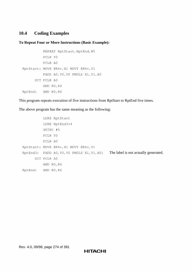
Rev. 4.0, 09/98, page 274 of 391
10.4 Coding Examples
To Repeat Four or More Instructions (Basic Example):
REPEAT RptStart,RptEnd,#5
PCLR Y0
PCLR A0
RptStart: MOVX @R4+,X1 MOVY @R6+,Y1
PADD A0,Y0,Y0 PMULS X1,Y1,A0
DCT PCLR A0
AND R0,R4
RptEnd: AND R0,R6
This program repeats execution of five instructions from RptStart to RptEnd five times.
The above program has the same meaning as the following:
LDRS RptStart
LDRE RptEnd3+4
SETRC #5
PCLR Y0
PCLR A0
RptStart: MOVX @R4+,X1 MOVY @R6+,Y1
RptEnd3: PADD A0,Y0,Y0 PMULS X1,Y1,A0; The label is not actually generated.
DCT PCLR A0
AND R0,R4
RptEnd: AND R0,R6
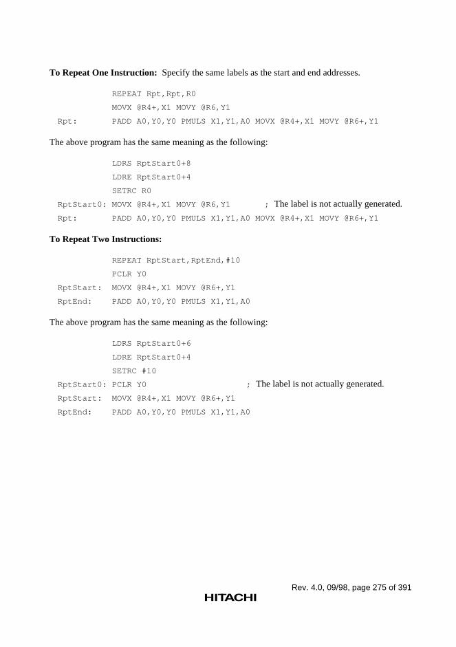
Rev. 4.0, 09/98, page 275 of 391
To Repeat One Instruction: Specify the same labels as the start and end addresses.
REPEAT Rpt,Rpt,R0
MOVX @R4+,X1 MOVY @R6,Y1
Rpt: PADD A0,Y0,Y0 PMULS X1,Y1,A0 MOVX @R4+,X1 MOVY @R6+,Y1
The above program has the same meaning as the following:
LDRS RptStart0+8
LDRE RptStart0+4
SETRC R0
RptStart0: MOVX @R4+,X1 MOVY @R6,Y1 ; The label is not actually generated.
Rpt: PADD A0,Y0,Y0 PMULS X1,Y1,A0 MOVX @R4+,X1 MOVY @R6+,Y1
To Repeat Two Instructions:
REPEAT RptStart,RptEnd,#10
PCLR Y0
RptStart: MOVX @R4+,X1 MOVY @R6+,Y1
RptEnd: PADD A0,Y0,Y0 PMULS X1,Y1,A0
The above program has the same meaning as the following:
LDRS RptStart0+6
LDRE RptStart0+4
SETRC #10
RptStart0: PCLR Y0 ; The label is not actually generated.
RptStart: MOVX @R4+,X1 MOVY @R6+,Y1
RptEnd: PADD A0,Y0,Y0 PMULS X1,Y1,A0
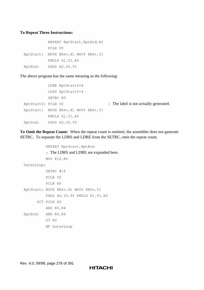
Rev. 4.0, 09/98, page 276 of 391
To Repeat Three Instructions:
REPEAT RptStart,RptEnd,R0
PCLR Y0
RptStart: MOVX @R4+,X1 MOVY @R6+,Y1
PMULS X1,Y1,A0
RptEnd: PADD A0,Y0,Y0
The above program has the same meaning as the following:
LDRE RptStart0+4
LDRS RptStart0+4
SETRC R0
RptStart0: PCLR Y0 ; The label is not actually generated.
RptStart: MOVX @R4+,X1 MOVY @R6+,Y1
PMULS X1,Y1,A0
RptEnd: PADD A0,Y0,Y0
To Omit the Repeat Count: When the repeat count is omitted, the assembler does not generateSETRC. To separate the LDRS and LDRE from the SETRC, omit the repeat count.
REPEAT RptStart,RptEnd
; The LDRS and LDRE are expanded here.
MOV #10,R0
OuterLoop:
SETRC #16
PCLR Y0
PCLR A0
RptStart: MOVX @R4+,X1 MOVY @R6+,Y1
PADD A0,Y0,Y0 PMULS X1,Y1,A0
DCT PCLR A0
AND R0,R4
RptEnd: AND R0,R6
DT R0
BF OuterLoop
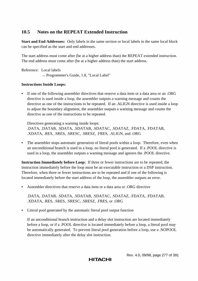
Rev. 4.0, 09/98, page 277 of 391
10.5 Notes on the REPEAT Extended Instruction
Start and End Addresses: Only labels in the same section or local labels in the same local blockcan be specified as the start and end addresses.
The start address must come after (be at a higher address than) the REPEAT extended instruction.The end address must come after (be at a higher address than) the start address.
Reference: Local labels→ Programmer's Guide, 1.8, "Local Label"
Instructions Inside Loops:
• If one of the following assembler directives that reserve a data item or a data area or an .ORGdirective is used inside a loop, the assembler outputs a warning message and counts thedirective as one of the instructions to be repeated. If an .ALIGN directive is used inside a loopto adjust the boundary alignment, the assembler outputs a warning message and counts thedirective as one of the instructions to be repeated.
Directives generating a warning inside loops:.DATA, .DATAB, .SDATA, .SDATAB, .SDATAC, .SDATAZ, .FDATA, .FDATAB,.XDATA, .RES, .SRES, .SRESC, .SRESZ, .FRES, .ALIGN, and .ORG
• The assembler stops automatic generation of literal pools within a loop. Therefore, even whenan unconditional branch is used in a loop, no literal pool is generated. If a .POOL directive isused in a loop, the assembler outputs a warning message and ignores the .POOL directive.
Instruction Immediately before Loop: If three or fewer instructions are to be repeated, theinstruction immediately before the loop must be an executable instruction or a DSP instruction.Therefore, when three or fewer instructions are to be repeated and if one of the following islocated immediately before the start address of the loop, the assembler outputs an error.
• Assembler directives that reserve a data item or a data area or .ORG directive
.DATA, .DATAB, .SDATA, .SDATAB, .SDATAC, .SDATAZ, .FDATA, .FDATAB,
.XDATA, .RES, .SRES, .SRESC, .SRESZ, .FRES, or .ORG
• Literal pool generated by the automatic literal pool output function
If an unconditional branch instruction and a delay slot instruction are located immediatelybefore a loop, or if a .POOL directive is located immediately before a loop, a literal pool maybe automatically generated. To prevent literal pool generation before a loop, use a .NOPOOLdirective immediately after the delay slot instruction.
Rev. 4.0, 09/98, page 278 of 391
• One alignment byte generated by an .ALIGN directive
When an .ALIGN directive is used immediately after an odd address before a loop, onealignment byte may be generated (for example, .ALIGN 4 is specified when the locationcounter value is 3). In this case, the contents of the byte before a loop is not an executableinstruction, and an error message is output. If two or more alignment bytes are generatedbefore a loop, their contents consist of a NOP instruction and the program can be correctlyexecuted.
Others:
• One or more executable or DSP instructions must be located between a REPEAT extendedinstruction and the start address. Otherwise, the assembler outputs an error message.
• A REPEAT extended instruction must not be located between another REPEAT extendedinstruction and its end address. If REPEAT extended instructions are nested, the assembleroutputs an error message; the first REPEAT is valid, and the other REPEAT instructions areignored.

User’s Guide
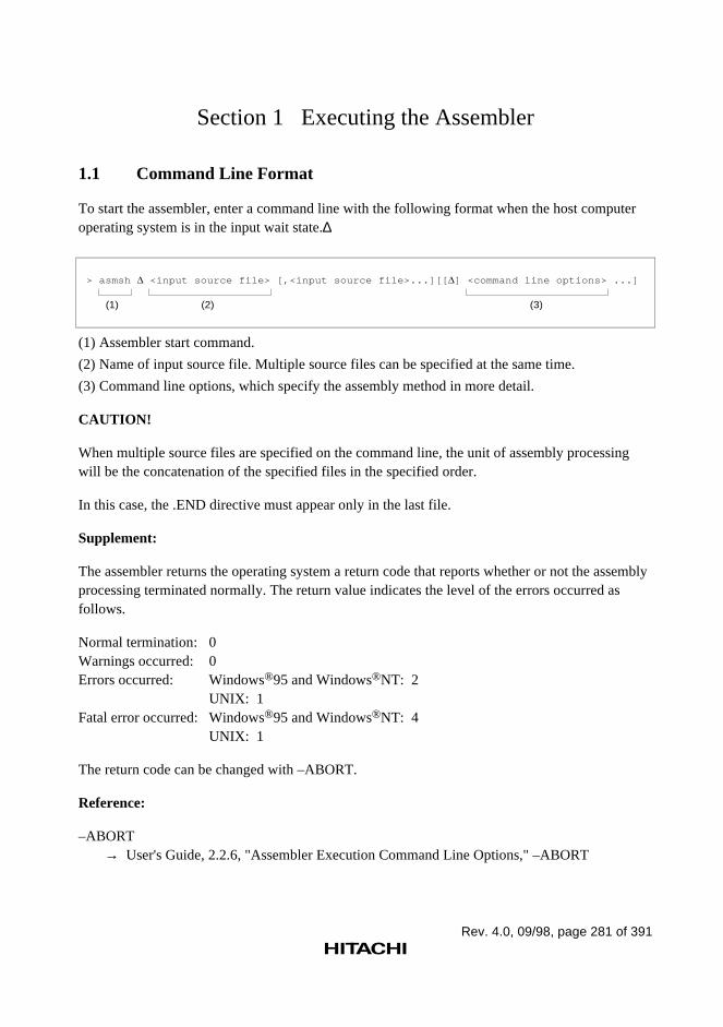
Rev. 4.0, 09/98, page 281 of 391
Section 1 Executing the Assembler
1.1 Command Line Format
To start the assembler, enter a command line with the following format when the host computeroperating system is in the input wait state.∆
> asmsh <input source file> [,<input source file>...][[ ] <command line options> ...]
(1) (2) (3)
(1) Assembler start command.
(2) Name of input source file. Multiple source files can be specified at the same time.
(3) Command line options, which specify the assembly method in more detail.
CAUTION!
When multiple source files are specified on the command line, the unit of assembly processingwill be the concatenation of the specified files in the specified order.
In this case, the .END directive must appear only in the last file.
Supplement:
The assembler returns the operating system a return code that reports whether or not the assemblyprocessing terminated normally. The return value indicates the level of the errors occurred asfollows.
Normal termination: 0Warnings occurred: 0Errors occurred: Windows®95 and Windows®NT: 2
UNIX: 1Fatal error occurred: Windows®95 and Windows®NT: 4
UNIX: 1
The return code can be changed with –ABORT.
Reference:
–ABORT→ User's Guide, 2.2.6, "Assembler Execution Command Line Options," –ABORT
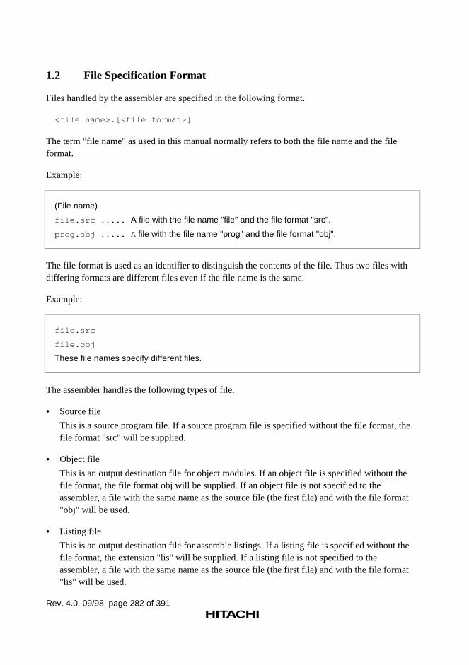
Rev. 4.0, 09/98, page 282 of 391
1.2 File Specification Format
Files handled by the assembler are specified in the following format.
<file name>.[<file format>]
The term "file name" as used in this manual normally refers to both the file name and the fileformat.
Example:
(File name)
file.src ..... A file with the file name "file" and the file format "src".
prog.obj ..... A file with the file name "prog" and the file format "obj".
The file format is used as an identifier to distinguish the contents of the file. Thus two files withdiffering formats are different files even if the file name is the same.
Example:
file.src
file.obj
These file names specify different files.
The assembler handles the following types of file.
• Source file
This is a source program file. If a source program file is specified without the file format, thefile format "src" will be supplied.
• Object file
This is an output destination file for object modules. If an object file is specified without thefile format, the file format obj will be supplied. If an object file is not specified to theassembler, a file with the same name as the source file (the first file) and with the file format"obj" will be used.
• Listing file
This is an output destination file for assemble listings. If a listing file is specified without thefile format, the extension "lis" will be supplied. If a listing file is not specified to theassembler, a file with the same name as the source file (the first file) and with the file format"lis" will be used.
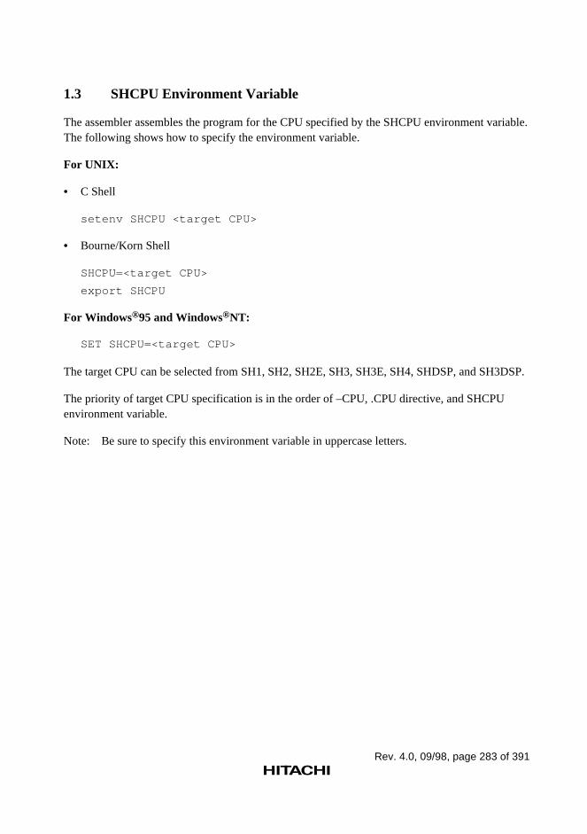
Rev. 4.0, 09/98, page 283 of 391
1.3 SHCPU Environment Variable
The assembler assembles the program for the CPU specified by the SHCPU environment variable.The following shows how to specify the environment variable.
For UNIX:
• C Shell
setenv SHCPU <target CPU>
• Bourne/Korn Shell
SHCPU=<target CPU>
export SHCPU
For Windows®95 and Windows®NT:
SET SHCPU=<target CPU>
The target CPU can be selected from SH1, SH2, SH2E, SH3, SH3E, SH4, SHDSP, and SH3DSP.
The priority of target CPU specification is in the order of –CPU, .CPU directive, and SHCPUenvironment variable.
Note: Be sure to specify this environment variable in uppercase letters.
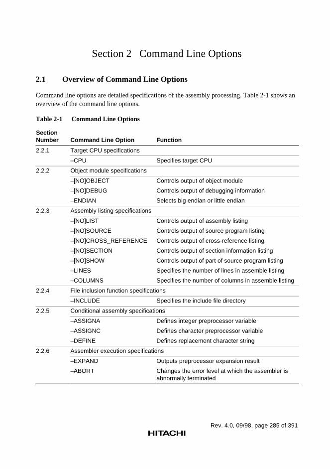
Rev. 4.0, 09/98, page 285 of 391
Section 2 Command Line Options
2.1 Overview of Command Line Options
Command line options are detailed specifications of the assembly processing. Table 2-1 shows anoverview of the command line options.
Table 2-1 Command Line Options
SectionNumber Command Line Option Function
2.2.1 Target CPU specifications
–CPU Specifies target CPU
2.2.2 Object module specifications
–[NO]OBJECT
–[NO]DEBUG
–ENDIAN
Controls output of object module
Controls output of debugging information
Selects big endian or little endian
2.2.3 Assembly listing specifications
–[NO]LIST
–[NO]SOURCE
–[NO]CROSS_REFERENCE
–[NO]SECTION
–[NO]SHOW
–LINES
–COLUMNS
Controls output of assembly listing
Controls output of source program listing
Controls output of cross-reference listing
Controls output of section information listing
Controls output of part of source program listing
Specifies the number of lines in assemble listing
Specifies the number of columns in assemble listing
2.2.4 File inclusion function specifications
–INCLUDE Specifies the include file directory
2.2.5 Conditional assembly specifications
–ASSIGNA
–ASSIGNC
–DEFINE
Defines integer preprocessor variable
Defines character preprocessor variable
Defines replacement character string
2.2.6 Assembler execution specifications
–EXPAND
–ABORT
Outputs preprocessor expansion result
Changes the error level at which the assembler isabnormally terminated
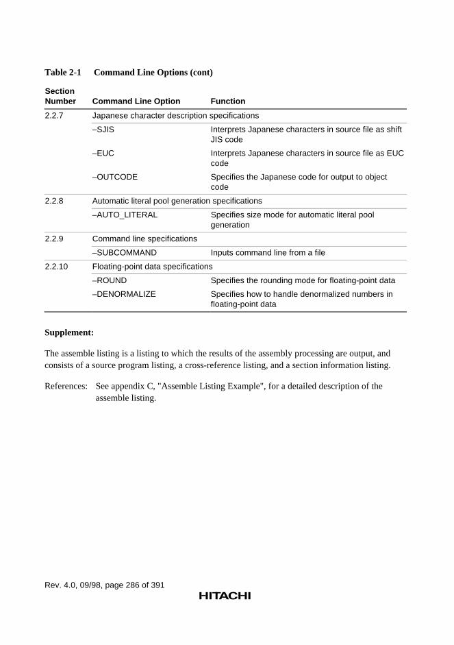
Rev. 4.0, 09/98, page 286 of 391
Table 2-1 Command Line Options (cont)
SectionNumber Command Line Option Function
2.2.7 Japanese character description specifications
–SJIS
–EUC
–OUTCODE
Interprets Japanese characters in source file as shiftJIS code
Interprets Japanese characters in source file as EUCcode
Specifies the Japanese code for output to objectcode
2.2.8 Automatic literal pool generation specifications
–AUTO_LITERAL Specifies size mode for automatic literal poolgeneration
2.2.9 Command line specifications
–SUBCOMMAND Inputs command line from a file
2.2.10 Floating-point data specifications
–ROUND
–DENORMALIZE
Specifies the rounding mode for floating-point data
Specifies how to handle denormalized numbers infloating-point data
Supplement:
The assemble listing is a listing to which the results of the assembly processing are output, andconsists of a source program listing, a cross-reference listing, and a section information listing.
References: See appendix C, "Assemble Listing Example", for a detailed description of theassemble listing.
Rev. 4.0, 09/98, page 287 of 391
2.2 Command Line Option Reference
2.2.1 Target CPU Command Line Option
This assembler provides the following command line option concerned with the target CPU.
–CPU
This command line option specifies the target CPU.
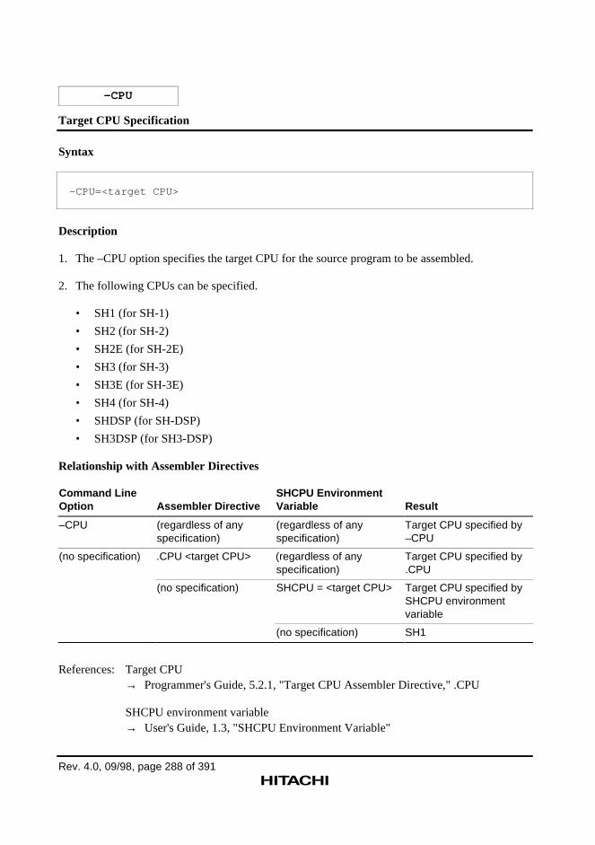
Rev. 4.0, 09/98, page 288 of 391
–CPU
Target CPU Specification
Syntax
–CPU=<target CPU>
Description
1. The –CPU option specifies the target CPU for the source program to be assembled.
2. The following CPUs can be specified.
• SH1 (for SH-1)
• SH2 (for SH-2)
• SH2E (for SH-2E)
• SH3 (for SH-3)
• SH3E (for SH-3E)
• SH4 (for SH-4)
• SHDSP (for SH-DSP)
• SH3DSP (for SH3-DSP)
Relationship with Assembler Directives
Command LineOption Assembler Directive
SHCPU EnvironmentVariable Result
–CPU (regardless of anyspecification)
(regardless of anyspecification)
Target CPU specified by–CPU
(no specification) .CPU <target CPU> (regardless of anyspecification)
Target CPU specified by.CPU
(no specification) SHCPU = <target CPU> Target CPU specified bySHCPU environmentvariable
(no specification) SH1
References: Target CPU→ Programmer's Guide, 5.2.1, "Target CPU Assembler Directive," .CPU
SHCPU environment variable→ User's Guide, 1.3, "SHCPU Environment Variable"
Rev. 4.0, 09/98, page 289 of 391
2.2.2 Object Module Command Line Options
This assembler provides the following command line options concerned with object modules.
–OBJECT –NOOBJECT
These command line options control output of an object module.
–DEBUG –NODEBUG
These command line options control output of debug information.
–ENDIAN
This command line option selects big endian or little endian.
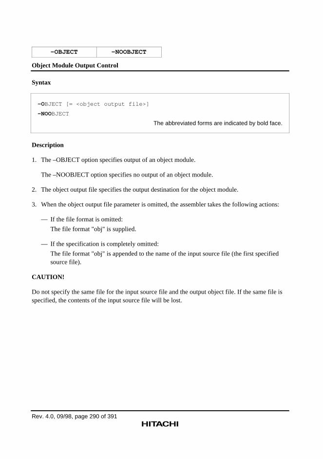
Rev. 4.0, 09/98, page 290 of 391
–OBJECT –NOOBJECT
Object Module Output Control
Syntax
–OBJECT [= <object output file>]
–NOOBJECT
The abbreviated forms are indicated by bold face.
Description
1. The –OBJECT option specifies output of an object module.
The –NOOBJECT option specifies no output of an object module.
2. The object output file specifies the output destination for the object module.
3. When the object output file parameter is omitted, the assembler takes the following actions:
— If the file format is omitted:
The file format "obj" is supplied.
— If the specification is completely omitted:
The file format "obj" is appended to the name of the input source file (the first specifiedsource file).
CAUTION!
Do not specify the same file for the input source file and the output object file. If the same file isspecified, the contents of the input source file will be lost.
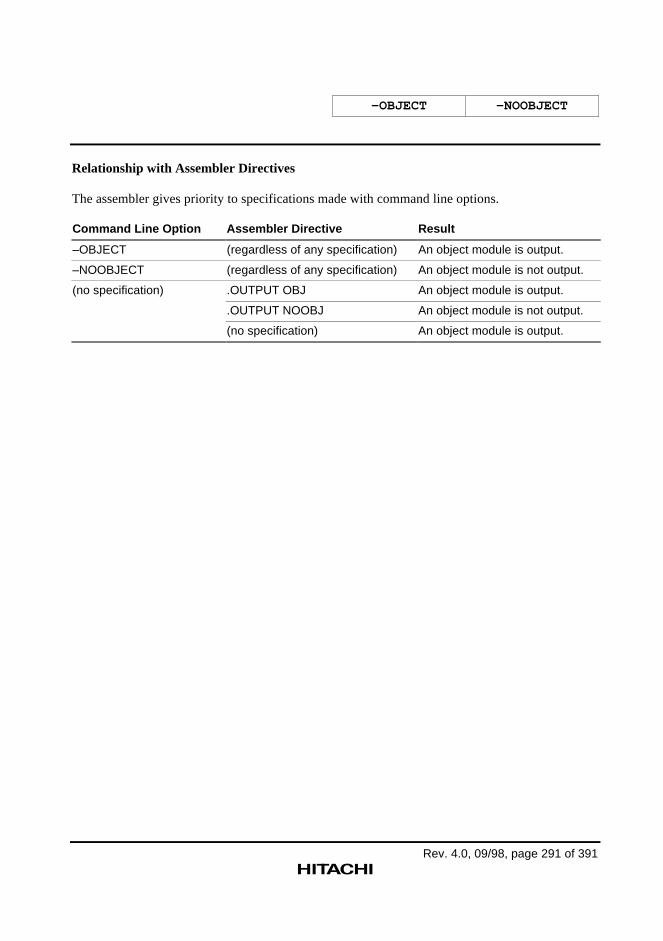
–OBJECT –NOOBJECT
Rev. 4.0, 09/98, page 291 of 391
Relationship with Assembler Directives
The assembler gives priority to specifications made with command line options.
Command Line Option Assembler Directive Result
–OBJECT (regardless of any specification) An object module is output.
–NOOBJECT (regardless of any specification) An object module is not output.
(no specification) .OUTPUT OBJ An object module is output.
.OUTPUT NOOBJ An object module is not output.
(no specification) An object module is output.
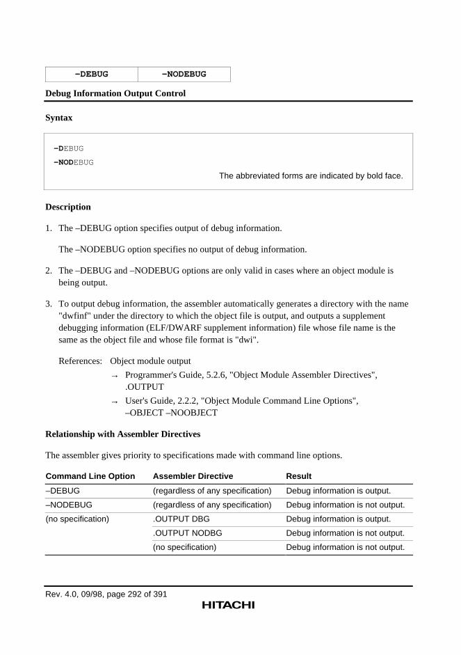
Rev. 4.0, 09/98, page 292 of 391
–DEBUG –NODEBUG
Debug Information Output Control
Syntax
–DEBUG
–NODEBUG
The abbreviated forms are indicated by bold face.
Description
1. The –DEBUG option specifies output of debug information.
The –NODEBUG option specifies no output of debug information.
2. The –DEBUG and –NODEBUG options are only valid in cases where an object module isbeing output.
3. To output debug information, the assembler automatically generates a directory with the name"dwfinf" under the directory to which the object file is output, and outputs a supplementdebugging information (ELF/DWARF supplement information) file whose file name is thesame as the object file and whose file format is "dwi".
References: Object module output
→ Programmer's Guide, 5.2.6, "Object Module Assembler Directives",.OUTPUT
→ User's Guide, 2.2.2, "Object Module Command Line Options",–OBJECT –NOOBJECT
Relationship with Assembler Directives
The assembler gives priority to specifications made with command line options.
Command Line Option Assembler Directive Result
–DEBUG (regardless of any specification) Debug information is output.
–NODEBUG (regardless of any specification) Debug information is not output.
(no specification) .OUTPUT DBG Debug information is output.
.OUTPUT NODBG Debug information is not output.
(no specification) Debug information is not output.
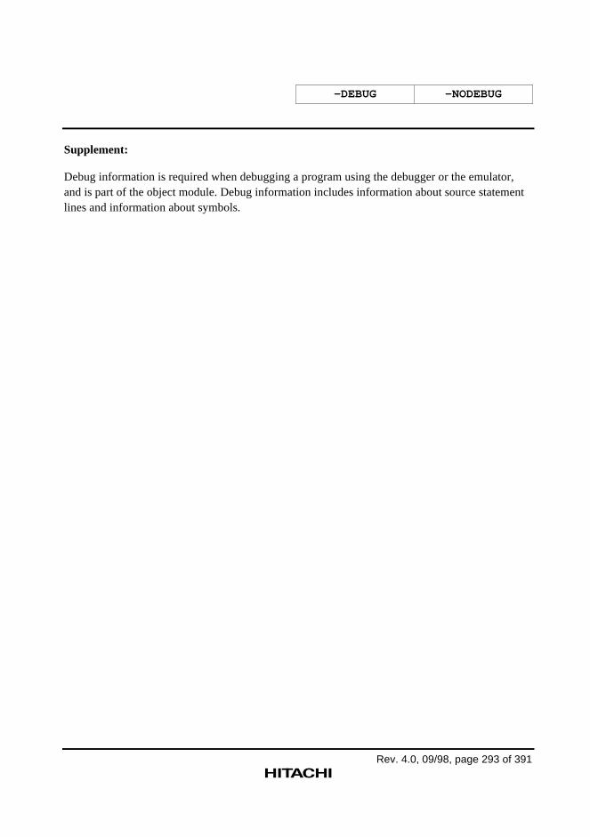
-DEBUG -NODEBUG
Rev. 4.0, 09/98, page 293 of 391
Supplement:
Debug information is required when debugging a program using the debugger or the emulator,and is part of the object module. Debug information includes information about source statementlines and information about symbols.
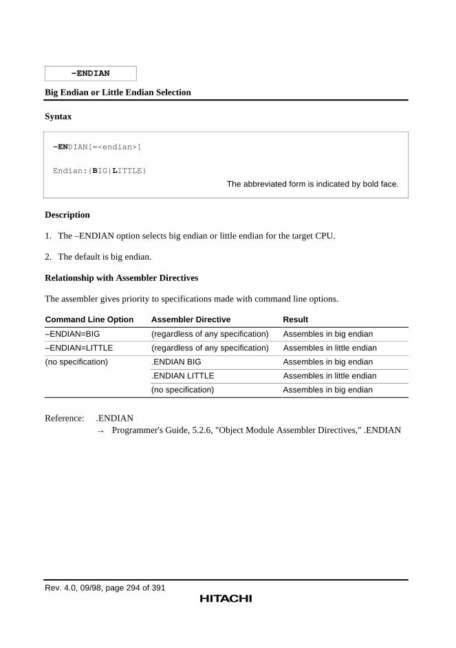
Rev. 4.0, 09/98, page 294 of 391
–ENDIAN
Big Endian or Little Endian Selection
Syntax
–ENDIAN[=<endian>]
Endian:{ BIG| LITTLE}
The abbreviated form is indicated by bold face.
Description
1. The –ENDIAN option selects big endian or little endian for the target CPU.
2. The default is big endian.
Relationship with Assembler Directives
The assembler gives priority to specifications made with command line options.
Command Line Option Assembler Directive Result
–ENDIAN=BIG (regardless of any specification) Assembles in big endian
–ENDIAN=LITTLE (regardless of any specification) Assembles in little endian
(no specification) .ENDIAN BIG Assembles in big endian
.ENDIAN LITTLE Assembles in little endian
(no specification) Assembles in big endian
Reference: .ENDIAN→ Programmer's Guide, 5.2.6, "Object Module Assembler Directives," .ENDIAN
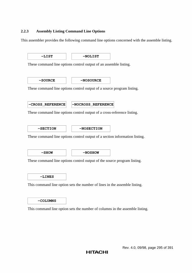
Rev. 4.0, 09/98, page 295 of 391
2.2.3 Assembly Listing Command Line Options
This assembler provides the following command line options concerned with the assemble listing.
–LIST –NOLIST
These command line options control output of an assemble listing.
–SOURCE –NOSOURCE
These command line options control output of a source program listing.
–CROSS_REFERENCE –NOCROSS_REFERENCE
These command line options control output of a cross-reference listing.
–SECTION –NOSECTION
These command line options control output of a section information listing.
–SHOW –NOSHOW
These command line options control output of the source program listing.
–LINES
This command line option sets the number of lines in the assemble listing.
–COLUMNS
This command line option sets the number of columns in the assemble listing.

Rev. 4.0, 09/98, page 296 of 391
–LIST –NOLIST
Assemble Listing Output Control
Syntax
–LIS T [ =<listing output file> ]
–NOLIST
The abbreviated forms are indicated by bold face.
Description
1. The –LIST option specifies output of an assemble listing.
The –NOLIST option specifies no output of an assemble listing.
2. The listing output file specifies the output destination file for the assemble listing.
3. When the listing output file parameter is omitted, the assembler takes the following actions:
— If the file format is omitted:
The file format "lis" is supplied.
— If the specification is completely omitted:
The file format "lis" is appended to the name of the input source file (the first specifiedsource file).
CAUTION!
Do not specify the same file for the input source file and the output object file. If the same file isspecified, the contents of the input source file will be lost.
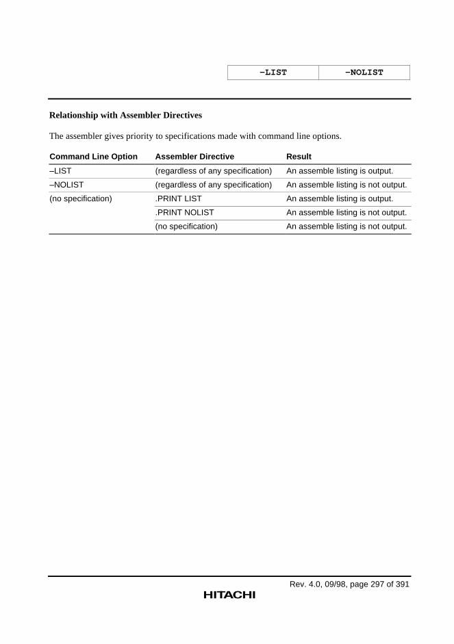
–LIST –NOLIST
Rev. 4.0, 09/98, page 297 of 391
Relationship with Assembler Directives
The assembler gives priority to specifications made with command line options.
Command Line Option Assembler Directive Result
–LIST (regardless of any specification) An assemble listing is output.
–NOLIST (regardless of any specification) An assemble listing is not output.
(no specification) .PRINT LIST An assemble listing is output.
.PRINT NOLIST An assemble listing is not output.
(no specification) An assemble listing is not output.
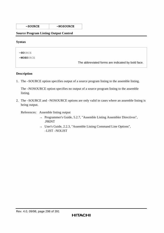
Rev. 4.0, 09/98, page 298 of 391
–SOURCE –NOSOURCE
Source Program Listing Output Control
Syntax
–SOURCE
–NOSOURCE
The abbreviated forms are indicated by bold face.
Description
1. The –SOURCE option specifies output of a source program listing to the assemble listing.
The –NOSOURCE option specifies no output of a source program listing to the assemblelisting.
2. The –SOURCE and –NOSOURCE options are only valid in cases where an assemble listing isbeing output.
References: Assemble listing output
→ Programmer's Guide, 5.2.7, "Assemble Listing Assembler Directives",.PRINT
→ User's Guide, 2.2.3, "Assemble Listing Command Line Options",–LIST –NOLIST
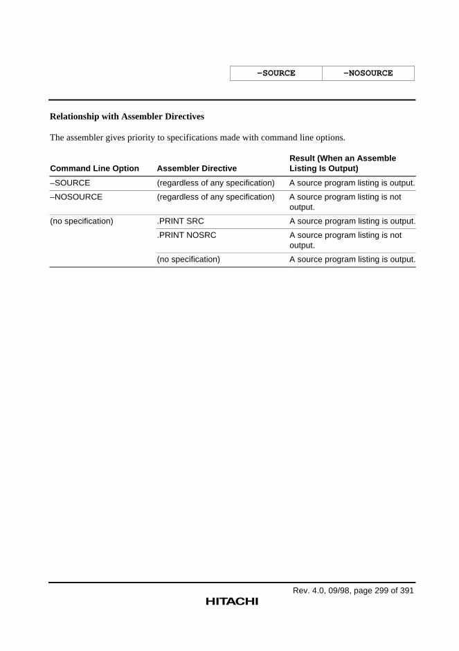
–SOURCE –NOSOURCE
Rev. 4.0, 09/98, page 299 of 391
Relationship with Assembler Directives
The assembler gives priority to specifications made with command line options.
Command Line Option Assembler DirectiveResult (When an AssembleListing Is Output)
–SOURCE (regardless of any specification) A source program listing is output.
–NOSOURCE (regardless of any specification) A source program listing is notoutput.
(no specification) .PRINT SRC A source program listing is output.
.PRINT NOSRC A source program listing is notoutput.
(no specification) A source program listing is output.
Rev. 4.0, 09/98, page 300 of 391
–CROSS_REFERENCE –NOCROSS_REFERENCE
Cross-Reference Listing Output Control
Syntax
–CROSS_REFERENCE
–NOCROSS_REFERENCE
The abbreviated forms are indicated by bold face.
Description
1. The –CROSS_REFERENCE option specifies output of a cross-reference listing to theassemble listing.
The –NOCROSS_REFERENCE option specifies no output of a cross-reference listing to theassemble listing.
2. The –CROSS_REFERENCE and –NOCROSS_REFERENCE options are only valid in caseswhere an assemble listing is being output.
References: Assemble listing output
→ Programmer's Guide, 5.2.7, "Assemble Listing Assembler Directives",.PRINT
→ User's Guide, 2.2.3, "Assemble Listing Command Line Options",–LIST –NOLIST
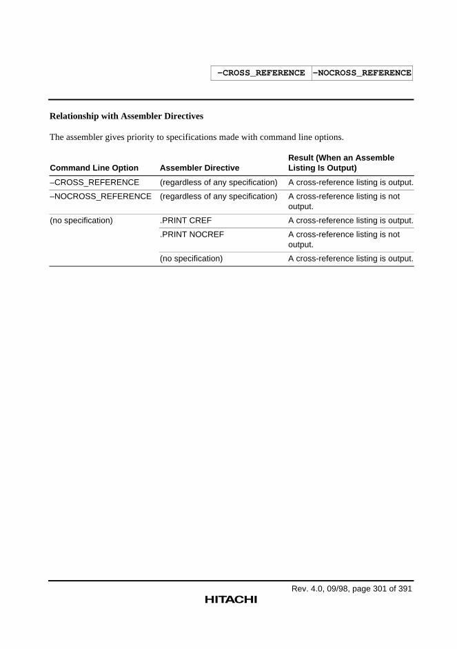
–CROSS_REFERENCE –NOCROSS_REFERENCE
Rev. 4.0, 09/98, page 301 of 391
Relationship with Assembler Directives
The assembler gives priority to specifications made with command line options.
Command Line Option Assembler DirectiveResult (When an AssembleListing Is Output)
–CROSS_REFERENCE (regardless of any specification) A cross-reference listing is output.
–NOCROSS_REFERENCE (regardless of any specification) A cross-reference listing is notoutput.
(no specification) .PRINT CREF A cross-reference listing is output.
.PRINT NOCREF A cross-reference listing is notoutput.
(no specification) A cross-reference listing is output.
Rev. 4.0, 09/98, page 302 of 391
–SECTION –NOSECTION
Section Information Listing Output Control
Syntax
–SECTION
–NOSECTION
The abbreviated forms are indicated by bold face.
Description
1. The –SECTION option specifies output of a section information listing to the assemble listing.
The –NOSECTION option specifies no output of a section information listing to the assemblelisting.
2. The –SECTION and –NOSECTION options are only valid in cases where an assemble listingis being output.
References: Assemble listing output
→ Programmer's Guide, 5.2.7, "Assemble Listing Assembler Directives",.PRINT
→ User's Guide, 2.2.3, "Assemble Listing Command Line Options",–LIST –NOLIST
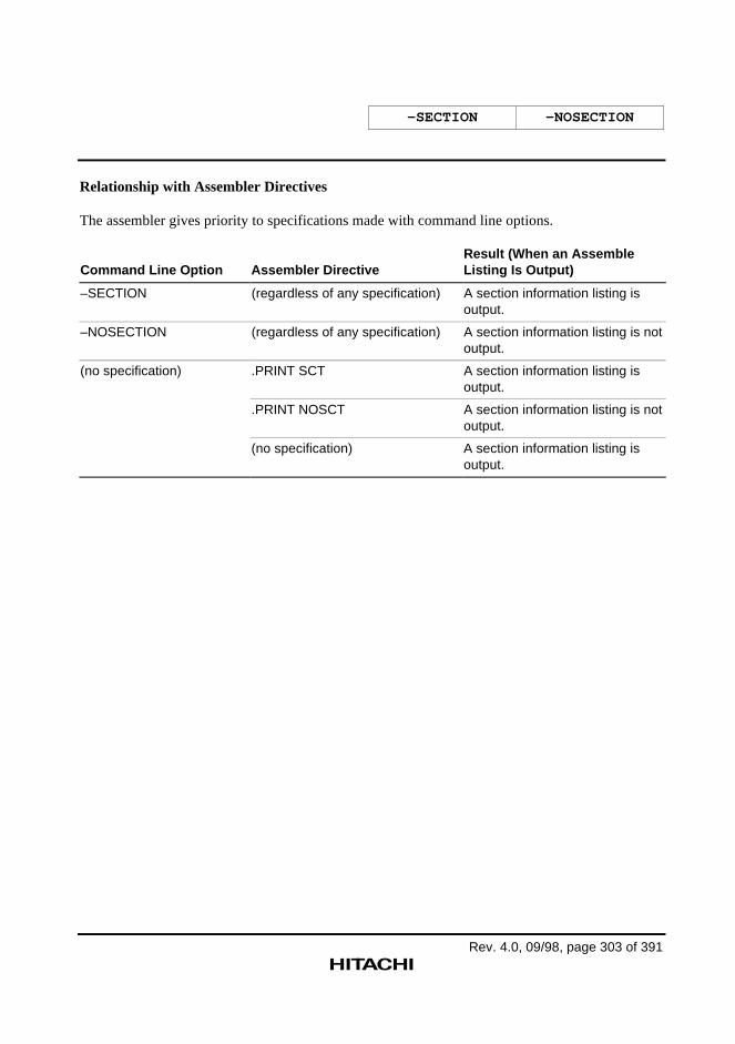
–SECTION –NOSECTION
Rev. 4.0, 09/98, page 303 of 391
Relationship with Assembler Directives
The assembler gives priority to specifications made with command line options.
Command Line Option Assembler DirectiveResult (When an AssembleListing Is Output)
–SECTION (regardless of any specification) A section information listing isoutput.
–NOSECTION (regardless of any specification) A section information listing is notoutput.
(no specification) .PRINT SCT A section information listing isoutput.
.PRINT NOSCT A section information listing is notoutput.
(no specification) A section information listing isoutput.
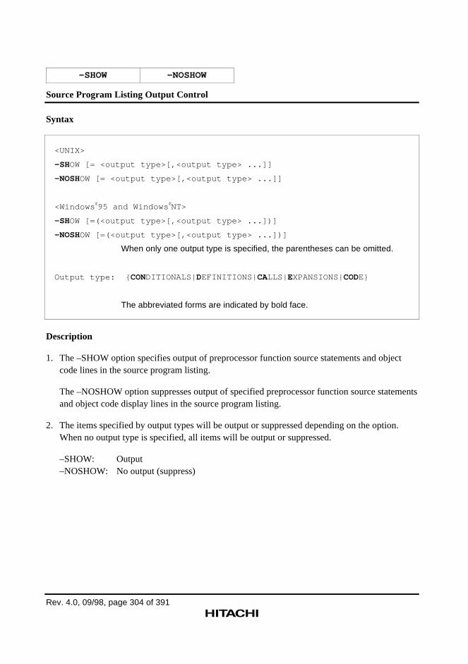
Rev. 4.0, 09/98, page 304 of 391
–SHOW –NOSHOW
Source Program Listing Output Control
Syntax
<UNIX>
–SHOW [= <output type>[,<output type> ...]]
–NOSHOW [= <output type>[,<output type> ...]]
<Windows Æ95 and Windows ÆNT>
–SHOW [=(<output type>[,<output type> ...])]
–NOSHOW [=(<output type>[,<output type> ...])]
When only one output type is specified, the parentheses can be omitted.
Output type: { CONDITIONALS| DEFINITIONS| CALLS| EXPANSIONS|CODE}
The abbreviated forms are indicated by bold face.
Description
1. The –SHOW option specifies output of preprocessor function source statements and objectcode lines in the source program listing.
The –NOSHOW option suppresses output of specified preprocessor function source statementsand object code display lines in the source program listing.
2. The items specified by output types will be output or suppressed depending on the option.When no output type is specified, all items will be output or suppressed.
–SHOW: Output–NOSHOW: No output (suppress)
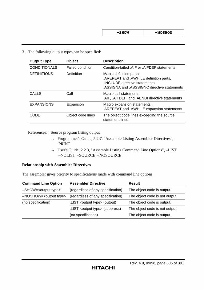
–SHOW –NOSHOW
Rev. 4.0, 09/98, page 305 of 391
3. The following output types can be specified:
Output Type Object Description
CONDITIONALS Failed condition Condition-failed .AIF or .AIFDEF statements
DEFINITIONS Definition Macro definition parts,.AREPEAT and .AWHILE definition parts,.INCLUDE directive statements.ASSIGNA and .ASSSIGNC directive statements
CALLS Call Macro call statements,.AIF, .AIFDEF, and .AENDI directive statements
EXPANSIONS Expansion Macro expansion statements.AREPEAT and .AWHILE expansion statements
CODE Object code lines The object code lines exceeding the sourcestatement lines
References: Source program listing output
→ Programmer's Guide, 5.2.7, "Assemble Listing Assembler Directives”,.PRINT
→ User's Guide, 2.2.3, "Assemble Listing Command Line Options”, –LIST –NOLIST –SOURCE –NOSOURCE
Relationship with Assembler Directives
The assembler gives priority to specifications made with command line options.
Command Line Option Assembler Directive Result
–SHOW=<output type> (regardless of any specification) The object code is output.
–NOSHOW=<output type> (regardless of any specification) The object code is not output.
(no specification) .LIST <output type> (output) The object code is output.
.LIST <output type> (suppress) The object code is not output.
(no specification) The object code is output.
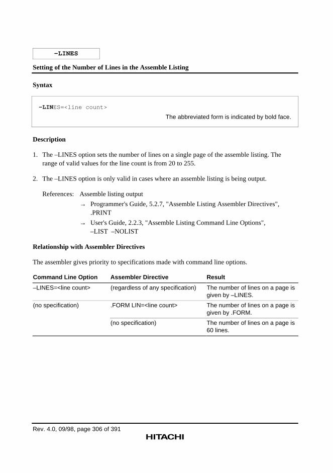
Rev. 4.0, 09/98, page 306 of 391
–LINES
Setting of the Number of Lines in the Assemble Listing
Syntax
–LIN ES=<line count>
The abbreviated form is indicated by bold face.
Description
1. The –LINES option sets the number of lines on a single page of the assemble listing. Therange of valid values for the line count is from 20 to 255.
2. The –LINES option is only valid in cases where an assemble listing is being output.
References: Assemble listing output
→ Programmer's Guide, 5.2.7, "Assemble Listing Assembler Directives",.PRINT
→ User's Guide, 2.2.3, "Assemble Listing Command Line Options",–LIST –NOLIST
Relationship with Assembler Directives
The assembler gives priority to specifications made with command line options.
Command Line Option Assembler Directive Result
–LINES=<line count> (regardless of any specification) The number of lines on a page isgiven by –LINES.
(no specification) .FORM LIN=<line count> The number of lines on a page isgiven by .FORM.
(no specification) The number of lines on a page is60 lines.
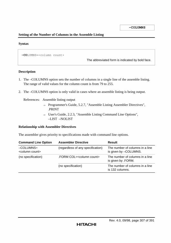
Rev. 4.0, 09/98, page 307 of 391
–COLUMNS
Setting of the Number of Columns in the Assemble Listing
Syntax
–COLUMNS=<column count>
The abbreviated form is indicated by bold face.
Description
1. The –COLUMNS option sets the number of columns in a single line of the assemble listing.The range of valid values for the column count is from 79 to 255.
2. The –COLUMNS option is only valid in cases where an assemble listing is being output.
References: Assemble listing output
→ Programmer's Guide, 5.2.7, "Assemble Listing Assembler Directives",.PRINT
→ User's Guide, 2.2.3, "Assemble Listing Command Line Options",–LIST –NOLIST
Relationship with Assembler Directives
The assembler gives priority to specifications made with command line options.
Command Line Option Assembler Directive Result
–COLUMNS=<column count>
(regardless of any specification) The number of columns in a lineis given by –COLUMNS.
(no specification) .FORM COL=<column count> The number of columns in a lineis given by .FORM.
(no specification) The number of columns in a lineis 132 columns.
Rev. 4.0, 09/98, page 308 of 391
2.2.4 File Inclusion Function Command Line Option
This assembler provides the following command line option concerned with the file inclusionfunction.
–INCLUDE
This command line option specifies the include file directory.
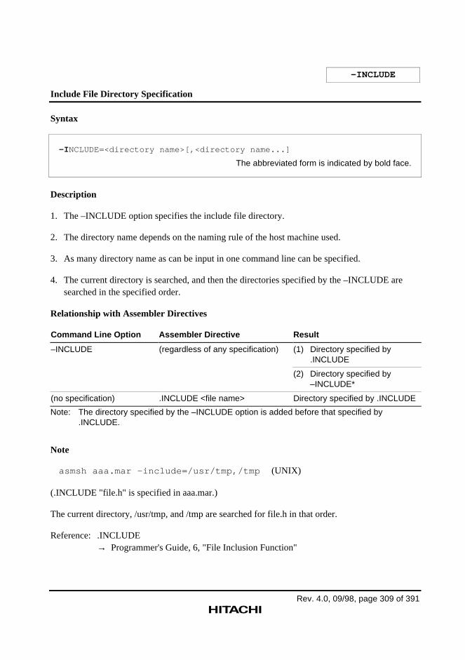
Rev. 4.0, 09/98, page 309 of 391
–INCLUDE
Include File Directory Specification
Syntax
–I NCLUDE=<directory name>[,<directory name...]
The abbreviated form is indicated by bold face.
Description
1. The –INCLUDE option specifies the include file directory.
2. The directory name depends on the naming rule of the host machine used.
3. As many directory name as can be input in one command line can be specified.
4. The current directory is searched, and then the directories specified by the –INCLUDE aresearched in the specified order.
Relationship with Assembler Directives
Command Line Option Assembler Directive Result
–INCLUDE (regardless of any specification) (1) Directory specified by.INCLUDE
(2) Directory specified by–INCLUDE*
(no specification) .INCLUDE <file name> Directory specified by .INCLUDE
Note: The directory specified by the –INCLUDE option is added before that specified by.INCLUDE.
Note
asmsh aaa.mar -include=/usr/tmp,/tmp (UNIX)
(.INCLUDE "file.h" is specified in aaa.mar.)
The current directory, /usr/tmp, and /tmp are searched for file.h in that order.
Reference: .INCLUDE→ Programmer's Guide, 6, "File Inclusion Function"
Rev. 4.0, 09/98, page 310 of 391
2.2.5 Conditional Assembly Command Line Options
This assembler provides the following command line options concerned with conditionalassembly.
–ASSIGNA
This command line option defines integer preprocessor variable.
–ASSIGNC
This command line option defines character preprocessor variable.
–DEFINE
This command line option defines replacement character string.
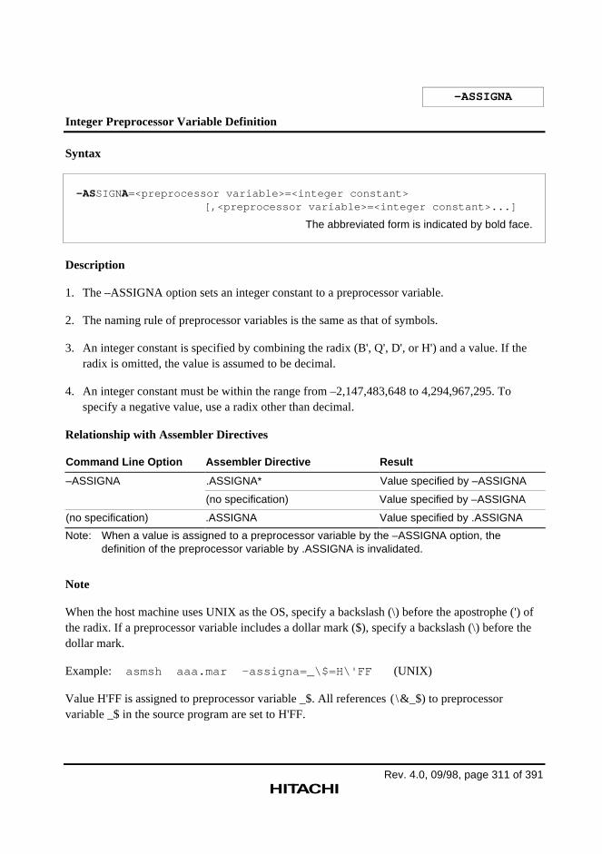
Rev. 4.0, 09/98, page 311 of 391
–ASSIGNA
Integer Preprocessor Variable Definition
Syntax
–ASSIGNA=<preprocessor variable>=<integer constant>[,<preprocessor variable>=<integer constant>...]
The abbreviated form is indicated by bold face.
Description
1. The –ASSIGNA option sets an integer constant to a preprocessor variable.
2. The naming rule of preprocessor variables is the same as that of symbols.
3. An integer constant is specified by combining the radix (B', Q', D', or H') and a value. If theradix is omitted, the value is assumed to be decimal.
4. An integer constant must be within the range from –2,147,483,648 to 4,294,967,295. Tospecify a negative value, use a radix other than decimal.
Relationship with Assembler Directives
Command Line Option Assembler Directive Result
–ASSIGNA .ASSIGNA* Value specified by –ASSIGNA
(no specification) Value specified by –ASSIGNA
(no specification) .ASSIGNA Value specified by .ASSIGNA
Note: When a value is assigned to a preprocessor variable by the –ASSIGNA option, thedefinition of the preprocessor variable by .ASSIGNA is invalidated.
Note
When the host machine uses UNIX as the OS, specify a backslash (\) before the apostrophe (') ofthe radix. If a preprocessor variable includes a dollar mark ($), specify a backslash (\) before thedollar mark.
Example: asmsh aaa.mar –assigna=_\$=H\'FF (UNIX)
Value H'FF is assigned to preprocessor variable _$. All references ( \&_$) to preprocessorvariable _$ in the source program are set to H'FF.
-ASSIGNA
Rev. 4.0, 09/98, page 312 of 391
Reference: .ASSIGNA→ Programmer's Guide, 7.2, "Conditional Assembly Directive," .ASSIGNA

Rev. 4.0, 09/98, page 313 of 391
–ASSIGNC
Character Preprocessor Variable Definition
Syntax
–ASSIGNC=<preprocessor variable>="<character string>"[,<preprocessor variable>="<character string>"...]
The abbreviated form is indicated by bold face.
Description
1. The –ASSIGNC option sets a character string to a preprocessor variable.
2. The naming rule of preprocessor variables is the same as that of symbols.
3. A character string must be enclosed with double-quotation marks (").
4. Up to 255 characters (bytes) can be specified for a character string.
Relationship with Assembler Directives
Command Line Option Assembler Directive Result
–ASSIGNC .ASSIGNC directive* Character string specified by –ASSIGNC
(no specification) Character string specified by –ASSIGNC
(no specification) .ASSIGNC directive Character string specified by .ASSIGNC
Note: When a character string is assigned to a preprocessor variable by the –ASSIGNC option,the definition of the preprocessor variable by .ASSIGNC is invalidated.
Note
To specify the following characters in a character string when the host machine uses UNIX as theOS, specify a backslash (\) before the characters. To specify character strings before and after thefollowing characters, enclose the character strings with double-quotation marks (").
• Exclamation mark (!)
• Double-quotation mark (")
• Dollar mark ($)
• Back quotation mark (`)
-ASSIGNC
Rev. 4.0, 09/98, page 314 of 391
asmsh aaa.mar -assignc=_\$="ON"\!"OFF" (UNIX)
Character string ON!OFF is assigned to preprocessor variable _$. All references (\&_$) topreprocessor variable _$ in the source program are set to ON!OFF.
Reference: .ASSIGNC→ Programmer's Guide, 7.2, "Conditional Assembly Directive," .ASSIGNC
Rev. 4.0, 09/98, page 315 of 391
–DEFINE
Replacement Character String Definition
Syntax
–DEFINE=<replacement symbol>="<character string>"[,<replacement symbol>="<character string>"...]
The abbreviated form is indicated by bold face.
Description
1. The –DEFINE option defines that the specified symbol is replaced with the correspondingcharacter string by the preprocessor.
2. Differences between –DEFINE and –ASSIGNC are the same as those between .DEFINE and.ASSIGNC.
Relationship with Assembler Directives
Command Line Option Assembler Directive Result
–DEFINE .DEFINE directive* Character string specified by –DEFINE
(no specification) Character string specified by –DEFINE
(no specification) .DEFINE directive Character string specified by .DEFINE
Note: When a character string is assigned to a replacement symbol by the –DEFINE option, thedefinition of the replacement symbol by .DEFINE is invalidated.
Reference: .DEFINE→ Programmer's Guide, 7.2, "Conditional Assembly Directive," .DEFINE
Rev. 4.0, 09/98, page 316 of 391
2.2.6 Assembler Execution Command Line Option
This assembler provides the following command line options concerned with assembler execution.
–EXPAND
This command line option outputs preprocessor expansion result.
–ABORT
This command line option changes the error level at which the assembler is abnormallyterminated.
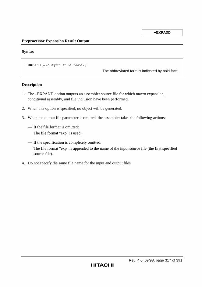
Rev. 4.0, 09/98, page 317 of 391
–EXPAND
Preprocessor Expansion Result Output
Syntax
–EXPAND[=<output file name>]
The abbreviated form is indicated by bold face.
Description
1. The –EXPAND option outputs an assembler source file for which macro expansion,conditional assembly, and file inclusion have been performed.
2. When this option is specified, no object will be generated.
3. When the output file parameter is omitted, the assembler takes the following actions:
— If the file format is omitted:
The file format "exp" is used.
— If the specification is completely omitted:
The file format "exp" is appended to the name of the input source file (the first specifiedsource file).
4. Do not specify the same file name for the input and output files.
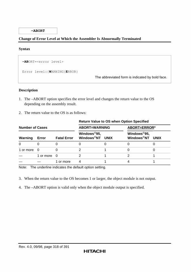
Rev. 4.0, 09/98, page 318 of 391
–ABORT
Change of Error Level at Which the Assembler Is Abnormally Terminated
Syntax
–ABORT=<error level>
Error level:{ WARNING|ERROR}
The abbreviated form is indicated by bold face.
Description
1. The –ABORT option specifies the error level and changes the return value to the OSdepending on the assembly result.
2. The return value to the OS is as follows:
Return Value to OS when Option Specified
Number of Cases ABORT=WARNING ABORT=ERROR*
Warning Error Fatal ErrorWindows ®95,Windows ®NT UNIX
Windows ®95,Windows ®NT UNIX
0 0 0 0 0 0 0
1 or more 0 0 2 1 0 0
— 1 or more 0 2 1 2 1
— — 1 or more 4 1 4 1
Note: The underline indicates the default option setting.
3. When the return value to the OS becomes 1 or larger, the object module is not output.
4. The –ABORT option is valid only when the object module output is specified.
Rev. 4.0, 09/98, page 319 of 391
2.2.7 Japanese Character Description Command Line Options
This assembler provides the following command line options concerned with Japanese charactersdescription in source files.
–SJIS
This command line option interprets Japanese kanji characters in source files as shift JIScode.
–EUC
This command line option interprets Japanese kanji characters in source files as EUC code.
–OUTCODE
This command line option specifies the Japanese kanji code for output to object file.
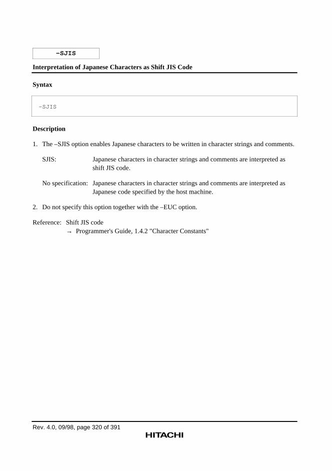
Rev. 4.0, 09/98, page 320 of 391
–SJIS
Interpretation of Japanese Characters as Shift JIS Code
Syntax
–SJIS
Description
1. The –SJIS option enables Japanese characters to be written in character strings and comments.
SJIS: Japanese characters in character strings and comments are interpreted asshift JIS code.
No specification: Japanese characters in character strings and comments are interpreted asJapanese code specified by the host machine.
2. Do not specify this option together with the –EUC option.
Reference: Shift JIS code→ Programmer's Guide, 1.4.2 "Character Constants"
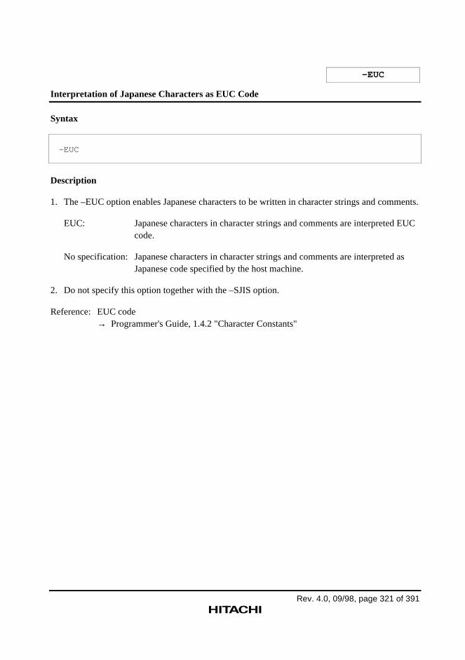
Rev. 4.0, 09/98, page 321 of 391
–EUC
Interpretation of Japanese Characters as EUC Code
Syntax
–EUC
Description
1. The –EUC option enables Japanese characters to be written in character strings and comments.
EUC: Japanese characters in character strings and comments are interpreted EUCcode.
No specification: Japanese characters in character strings and comments are interpreted asJapanese code specified by the host machine.
2. Do not specify this option together with the –SJIS option.
Reference: EUC code→ Programmer's Guide, 1.4.2 "Character Constants"
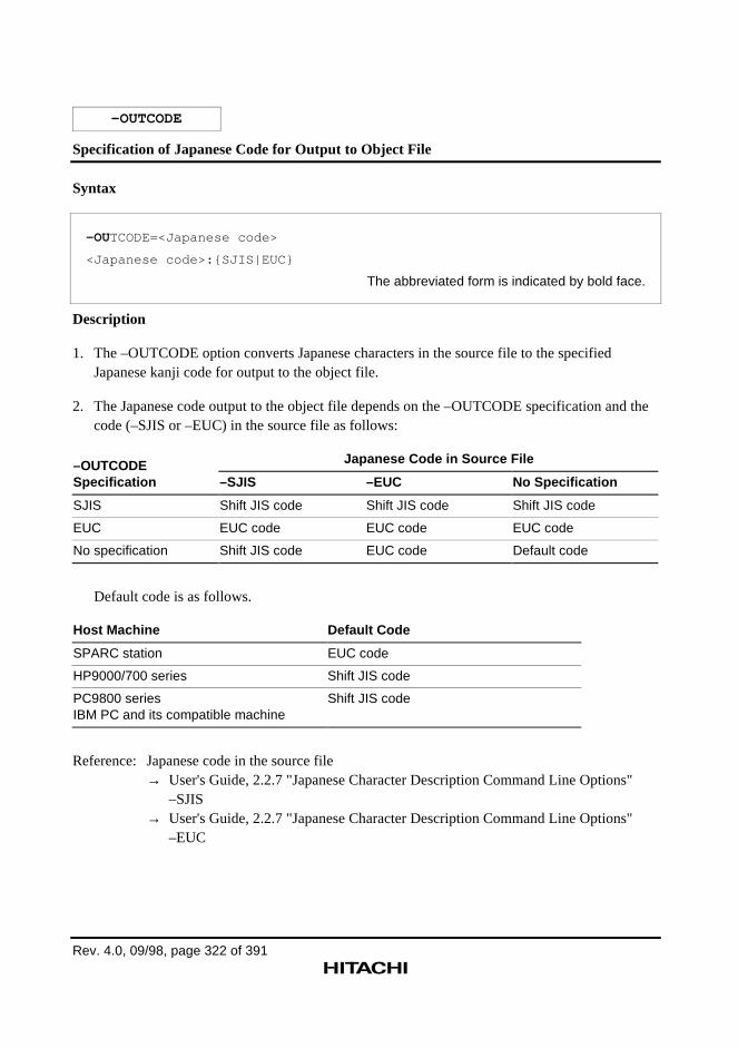
Rev. 4.0, 09/98, page 322 of 391
–OUTCODE
Specification of Japanese Code for Output to Object File
Syntax
–OUTCODE=<Japanese code>
<Japanese code>:{SJIS|EUC}
The abbreviated form is indicated by bold face.
Description
1. The –OUTCODE option converts Japanese characters in the source file to the specifiedJapanese kanji code for output to the object file.
2. The Japanese code output to the object file depends on the –OUTCODE specification and thecode (–SJIS or –EUC) in the source file as follows:
Japanese Code in Source File–OUTCODESpecification –SJIS –EUC No Specification
SJIS Shift JIS code Shift JIS code Shift JIS code
EUC EUC code EUC code EUC code
No specification Shift JIS code EUC code Default code
Default code is as follows.
Host Machine Default Code
SPARC station EUC code
HP9000/700 series Shift JIS code
PC9800 seriesIBM PC and its compatible machine
Shift JIS code
Reference: Japanese code in the source file→ User's Guide, 2.2.7 "Japanese Character Description Command Line Options"
–SJIS→ User's Guide, 2.2.7 "Japanese Character Description Command Line Options"
–EUC
Rev. 4.0, 09/98, page 323 of 391
2.2.8 Automatic Literal Pool Generation Command Line Option
This assembler provides the following command line option concerned with automatic literal poolgeneration.
–AUTO_LITERAL
This command line option specifies the size mode for automatic literal pool generation.
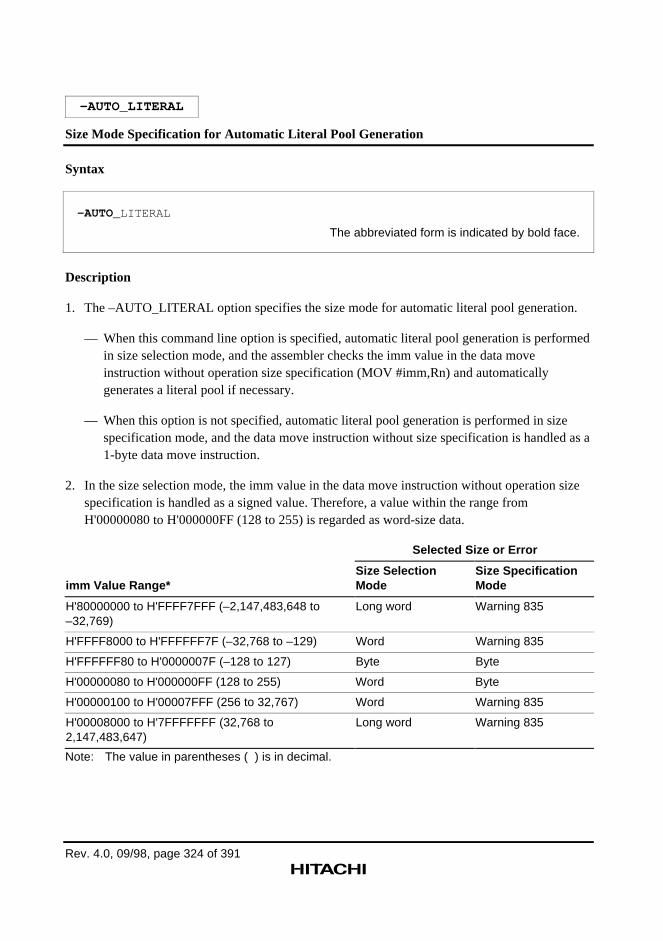
Rev. 4.0, 09/98, page 324 of 391
–AUTO_LITERAL
Size Mode Specification for Automatic Literal Pool Generation
Syntax
–AUTO_LITERAL
The abbreviated form is indicated by bold face.
Description
1. The –AUTO_LITERAL option specifies the size mode for automatic literal pool generation.
— When this command line option is specified, automatic literal pool generation is performedin size selection mode, and the assembler checks the imm value in the data moveinstruction without operation size specification (MOV #imm,Rn) and automaticallygenerates a literal pool if necessary.
— When this option is not specified, automatic literal pool generation is performed in sizespecification mode, and the data move instruction without size specification is handled as a1-byte data move instruction.
2. In the size selection mode, the imm value in the data move instruction without operation sizespecification is handled as a signed value. Therefore, a value within the range fromH'00000080 to H'000000FF (128 to 255) is regarded as word-size data.
Selected Size or Error
imm Value Range*Size SelectionMode
Size SpecificationMode
H'80000000 to H'FFFF7FFF (–2,147,483,648 to–32,769)
Long word Warning 835
H'FFFF8000 to H'FFFFFF7F (–32,768 to –129) Word Warning 835
H'FFFFFF80 to H'0000007F (–128 to 127) Byte Byte
H'00000080 to H'000000FF (128 to 255) Word Byte
H'00000100 to H'00007FFF (256 to 32,767) Word Warning 835
H'00008000 to H'7FFFFFFF (32,768 to2,147,483,647)
Long word Warning 835
Note: The value in parentheses ( ) is in decimal.
–AUTO_LITERAL
Rev. 4.0, 09/98, page 325 of 391
Reference: Size selection modeSize specification mode→ Programmer's Guide, 9.3 "Size Mode for Automatic Literal Pool Generation"
Rev. 4.0, 09/98, page 326 of 391
2.2.9 Command Line Input Command Line Option
This assembler provides the following command line option concerned with command line input.
–SUBCOMMAND
This command line option inputs command line specifications from a file.
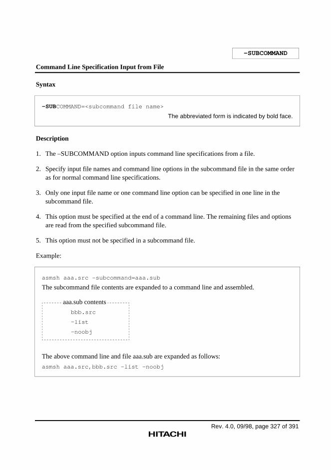
Rev. 4.0, 09/98, page 327 of 391
–SUBCOMMAND
Command Line Specification Input from File
Syntax
–SUBCOMMAND=<subcommand file name>
The abbreviated form is indicated by bold face.
Description
1. The –SUBCOMMAND option inputs command line specifications from a file.
2. Specify input file names and command line options in the subcommand file in the same orderas for normal command line specifications.
3. Only one input file name or one command line option can be specified in one line in thesubcommand file.
4. This option must be specified at the end of a command line. The remaining files and optionsare read from the specified subcommand file.
5. This option must not be specified in a subcommand file.
Example:
asmsh aaa.src -subcommand=aaa.sub
The subcommand file contents are expanded to a command line and assembled.
aaa.sub contents
bbb.src
-list
-noobj
The above command line and file aaa.sub are expanded as follows:
asmsh aaa.src,bbb.src -list -noobj
-SUBCOMMAND
Rev. 4.0, 09/98, page 328 of 391
Notes
1. One line of a subcommand file can include a maximum of 300 bytes.
2. One subcommand file can include a maximum of 32,767 bytes.
Rev. 4.0, 09/98, page 329 of 391
2.2.10 Floating-Point Data Command Line Options
This assembler provides the following command line options concerned with floating-point data.
–ROUND
This command line option specifies the rounding mode for floating-point data.
–DENORMALIZE
This command line option specifies how to handle denormalized numbers in floating-pointdata.
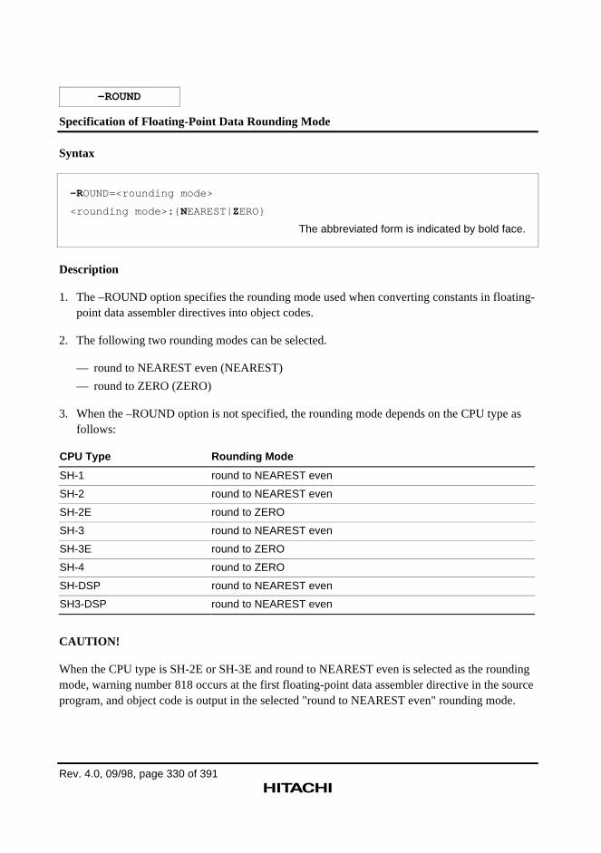
Rev. 4.0, 09/98, page 330 of 391
–ROUND
Specification of Floating-Point Data Rounding Mode
Syntax
–ROUND=<rounding mode>
<rounding mode>:{ NEAREST|ZERO}
The abbreviated form is indicated by bold face.
Description
1. The –ROUND option specifies the rounding mode used when converting constants in floating-point data assembler directives into object codes.
2. The following two rounding modes can be selected.
— round to NEAREST even (NEAREST)
— round to ZERO (ZERO)
3. When the –ROUND option is not specified, the rounding mode depends on the CPU type asfollows:
CPU Type Rounding Mode
SH-1 round to NEAREST even
SH-2 round to NEAREST even
SH-2E round to ZERO
SH-3 round to NEAREST even
SH-3E round to ZERO
SH-4 round to ZERO
SH-DSP round to NEAREST even
SH3-DSP round to NEAREST even
CAUTION!
When the CPU type is SH-2E or SH-3E and round to NEAREST even is selected as the roundingmode, warning number 818 occurs at the first floating-point data assembler directive in the sourceprogram, and object code is output in the selected "round to NEAREST even" rounding mode.
–ROUND
Rev. 4.0, 09/98, page 331 of 391
Reference: Rounding mode→ Programmer's Guide, 1.4.3 "Floating-Point Constants"
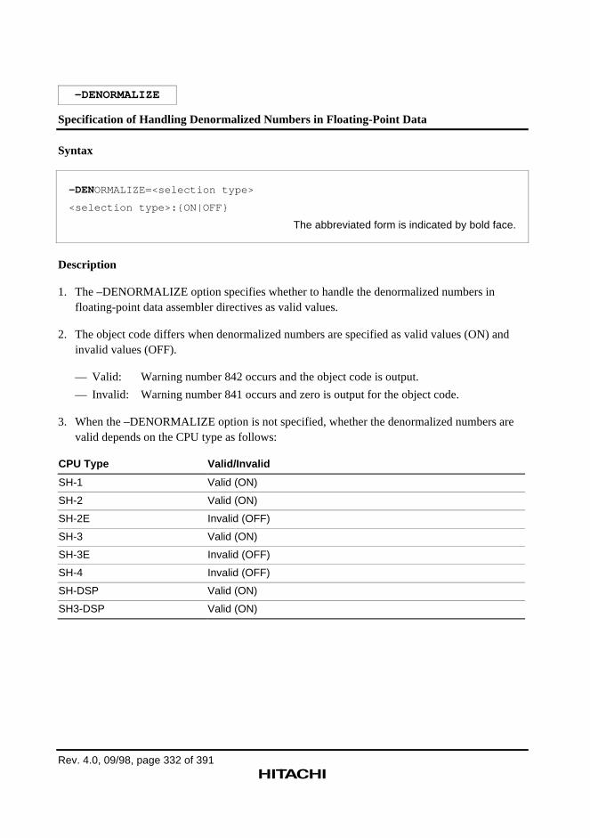
Rev. 4.0, 09/98, page 332 of 391
–DENORMALIZE
Specification of Handling Denormalized Numbers in Floating-Point Data
Syntax
–DENORMALIZE=<selection type>
<selection type>:{ON|OFF}
The abbreviated form is indicated by bold face.
Description
1. The –DENORMALIZE option specifies whether to handle the denormalized numbers infloating-point data assembler directives as valid values.
2. The object code differs when denormalized numbers are specified as valid values (ON) andinvalid values (OFF).
— Valid: Warning number 842 occurs and the object code is output.
— Invalid: Warning number 841 occurs and zero is output for the object code.
3. When the –DENORMALIZE option is not specified, whether the denormalized numbers arevalid depends on the CPU type as follows:
CPU Type Valid/Invalid
SH-1 Valid (ON)
SH-2 Valid (ON)
SH-2E Invalid (OFF)
SH-3 Valid (ON)
SH-3E Invalid (OFF)
SH-4 Invalid (OFF)
SH-DSP Valid (ON)
SH3-DSP Valid (ON)
–DENORMALIZE
Rev. 4.0, 09/98, page 333 of 391
CAUTION!
When the CPU type is SH-2E or SH-3E and denormalized numbers are specified as valid, warningnumber 818 occurs at the first floating-point data assembler directive in the source program, andobject code is output with the denormalized numbers handled as valid values as specified.
Reference: Denormalized numbers→ Programmer's Guide, 1.4.3 "Floating-Point Constants"

Appendix
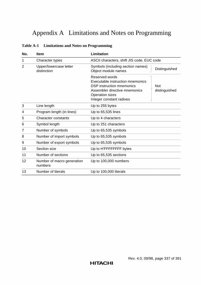
Rev. 4.0, 09/98, page 337 of 391
Appendix A Limitations and Notes on Programming
Table A-1 Limitations and Notes on Programming
No. Item Limitation
1 Character types ASCII characters, shift JIS code, EUC code
2 Upper/lowercase letterdistinction
Symbols (including section names)Object module names Distinguished
Reserved wordsExecutable instruction mnemonicsDSP instruction mnemonicsAssembler directive mnemonicsOperation sizesInteger constant radixes
Notdistinguished
3 Line length Up to 255 bytes
4 Program length (in lines) Up to 65,535 lines
5 Character constants Up to 4 characters
6 Symbol length Up to 251 characters
7 Number of symbols Up to 65,535 symbols
8 Number of import symbols Up to 65,535 symbols
9 Number of export symbols Up to 65,535 symbols
10 Section size Up to H'FFFFFFFF bytes
11 Number of sections Up to 65,535 sections
12 Number of macro generationnumbers
Up to 100,000 numbers
13 Number of literals Up to 100,000 literals
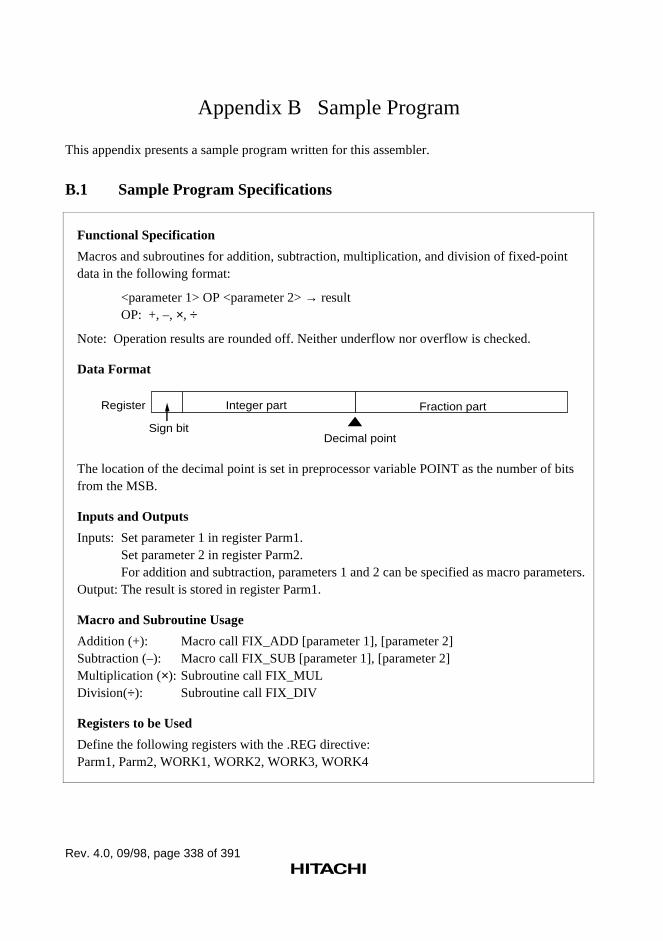
Rev. 4.0, 09/98, page 338 of 391
Appendix B Sample Program
This appendix presents a sample program written for this assembler.
B.1 Sample Program Specifications
Functional Specification
Macros and subroutines for addition, subtraction, multiplication, and division of fixed-pointdata in the following format:
<parameter 1> OP <parameter 2> → resultOP: +, –, ×, ÷
Note: Operation results are rounded off. Neither underflow nor overflow is checked.
Data Format
Register Integer part Fraction part
Decimal pointSign bit
The location of the decimal point is set in preprocessor variable POINT as the number of bitsfrom the MSB.
Inputs and Outputs
Inputs: Set parameter 1 in register Parm1.Set parameter 2 in register Parm2.For addition and subtraction, parameters 1 and 2 can be specified as macro parameters.
Output: The result is stored in register Parm1.
Macro and Subroutine Usage
Addition (+): Macro call FIX_ADD [parameter 1], [parameter 2]Subtraction (–): Macro call FIX_SUB [parameter 1], [parameter 2]Multiplication (×): Subroutine call FIX_MULDivision(÷): Subroutine call FIX_DIV
Registers to be Used
Define the following registers with the .REG directive:Parm1, Parm2, WORK1, WORK2, WORK3, WORK4
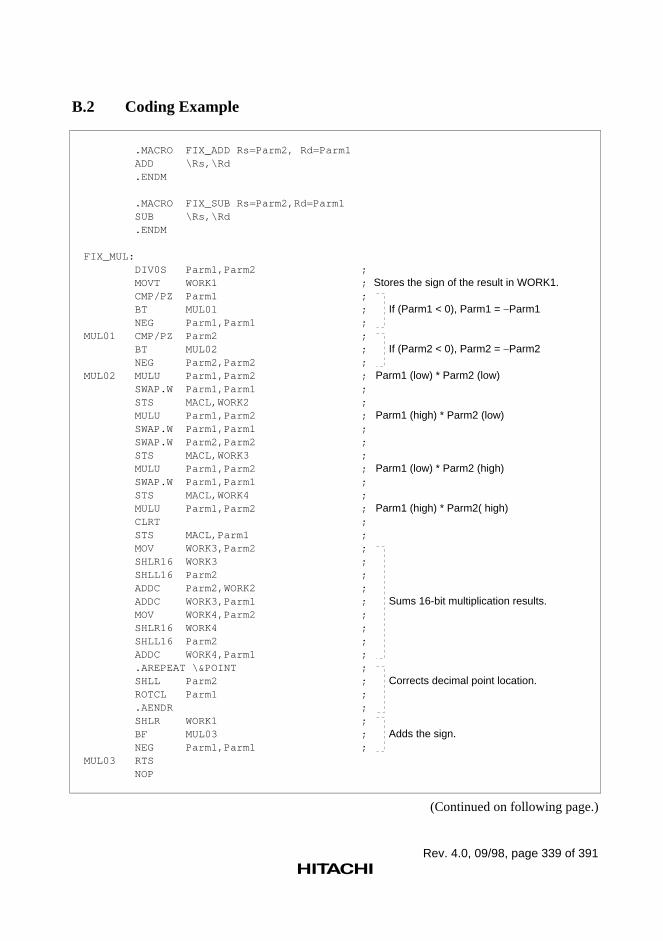
Rev. 4.0, 09/98, page 339 of 391
B.2 Coding Example
.MACRO FIX_ADD Rs=Parm2, Rd=Parm1 ADD \Rs,\Rd .ENDM
.MACRO FIX_SUB Rs=Parm2,Rd=Parm1 SUB \Rs,\Rd .ENDM
FIX_MUL: DIV0S Parm1,Parm2 ; MOVT WORK1 ; Stores the sign of the result in WORK1. CMP/PZ Parm1 ; BT MUL01 ; If (Parm1 < 0), Parm1 = Parm1 NEG Parm1,Parm1 ;MUL01 CMP/PZ Parm2 ; BT MUL02 ; If (Parm2 < 0), Parm2 = Parm2 NEG Parm2,Parm2 ;MUL02 MULU Parm1,Parm2 ; Parm1 (low) * Parm2 (low) SWAP.W Parm1,Parm1 ; STS MACL,WORK2 ; MULU Parm1,Parm2 ; Parm1 (high) * Parm2 (low) SWAP.W Parm1,Parm1 ; SWAP.W Parm2,Parm2 ; STS MACL,WORK3 ; MULU Parm1,Parm2 ; Parm1 (low) * Parm2 (high) SWAP.W Parm1,Parm1 ; STS MACL,WORK4 ; MULU Parm1,Parm2 ; Parm1 (high) * Parm2( high) CLRT ; STS MACL,Parm1 ; MOV WORK3,Parm2 ; SHLR16 WORK3 ; SHLL16 Parm2 ; ADDC Parm2,WORK2 ; ADDC WORK3,Parm1 ; Sums 16-bit multiplication results. MOV WORK4,Parm2 ; SHLR16 WORK4 ; SHLL16 Parm2 ; ADDC WORK4,Parm1 ; .AREPEAT \&POINT ; SHLL Parm2 ; Corrects decimal point location. ROTCL Parm1 ; .AENDR ; SHLR WORK1 ; BF MUL03 ; Adds the sign. NEG Parm1,Parm1 ;MUL03 RTS NOP
(Continued on following page.)
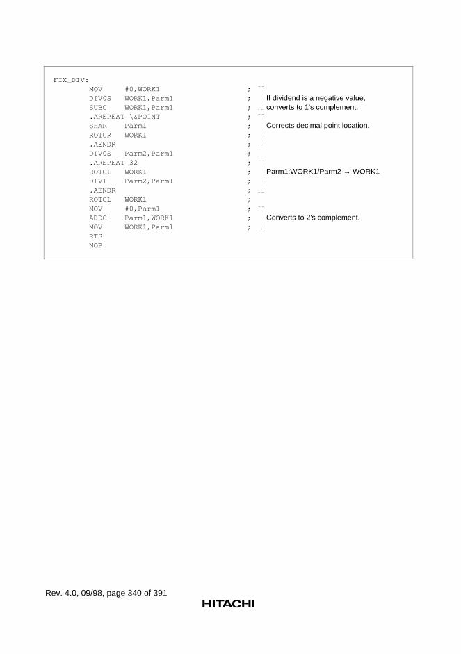
Rev. 4.0, 09/98, page 340 of 391
FIX_DIV: MOV #0,WORK1 ; DIV0S WORK1,Parm1 ; If dividend is a negative value, SUBC WORK1,Parm1 ; converts to 1's complement. .AREPEAT \&POINT ; SHAR Parm1 ; Corrects decimal point location. ROTCR WORK1 ; .AENDR ; DIV0S Parm2,Parm1 ; .AREPEAT 32 ; ROTCL WORK1 ; Parm1:WORK1/Parm2 → WORK1 DIV1 Parm2,Parm1 ; .AENDR ; ROTCL WORK1 ; MOV #0,Parm1 ; ADDC Parm1,WORK1 ; Converts to 2's complement. MOV WORK1,Parm1 ; RTS NOP
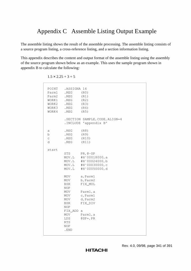
Rev. 4.0, 09/98, page 341 of 391
Appendix C Assemble Listing Output Example
The assemble listing shows the result of the assemble processing. The assemble listing consists ofa source program listing, a cross-reference listing, and a section information listing.
This appendix describes the content and output format of the assemble listing using the assemblyof the source program shown below as an example. This uses the sample program shown inappendix B to calculate the following:
1.5 × 2.25 + 3 ÷ 5
POINT .ASSIGNA 16Parm1 .REG (R0)Parm2 .REG (R1)WORK1 .REG (R2)WORK2 .REG (R3)WORK3 .REG (R4)WORK4 .REG (R5)
.SECTION SAMPLE,CODE,ALIGN=4 .INCLUDE "appendix B"
a .REG (R8)b .REG (R9)c .REG (R10)d .REG (R11)
start STS PR,@-SP MOV.L #H'00018000,a MOV.L #H'00024000,b MOV.L #H'00030000,c MOV.L #H'00050000,d
MOV a,Parm1 MOV b,Parm2 BSR FIX_MUL NOP MOV Parm1,a MOV c,Parm1 MOV d,Parm2 BSR FIX_DIV NOP FIX_ADD a MOV Parm1,a LDS @SP+,PR RTS NOP .END
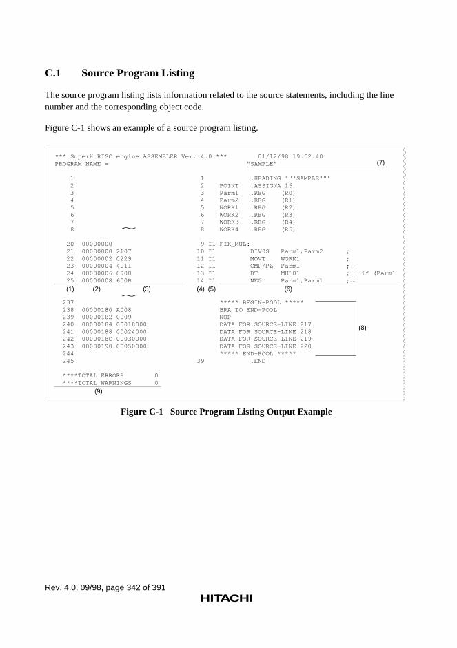
Rev. 4.0, 09/98, page 342 of 391
C.1 Source Program Listing
The source program listing lists information related to the source statements, including the linenumber and the corresponding object code.
Figure C-1 shows an example of a source program listing.
*** SuperH RISC engine ASSEMBLER Ver. 4.0 *** 01/12/98 19:52:40PROGRAM NAME = "SAMPLE"
1 1 .HEADING """SAMPLE""" 2 2 POINT .ASSIGNA 16 3 3 Parm1 .REG (R0) 4 4 Parm2 .REG (R1) 5 5 WORK1 .REG (R2) 6 6 WORK2 .REG (R3) 7 7 WORK3 .REG (R4) 8 8 WORK4 .REG (R5) 20 00000000 9 I1 FIX_MUL: 21 00000000 2107 10 I1 DIV0S Parm1,Parm2 ; 22 00000002 0229 11 I1 MOVT WORK1 ; 23 00000004 4011 12 I1 CMP/PZ Parm1 ; 24 00000006 8900 13 I1 BT MUL01 ; if (Parm1 25 00000008 600B 14 I1 NEG Parm1,Parm1 ; 237 ***** BEGIN-POOL ***** 238 00000180 A008 BRA TO END-POOL 239 00000182 0009 NOP 240 00000184 00018000 DATA FOR SOURCE-LINE 217 241 00000188 00024000 DATA FOR SOURCE-LINE 218 242 0000018C 00030000 DATA FOR SOURCE-LINE 219 243 00000190 00050000 DATA FOR SOURCE-LINE 220 244 ***** END-POOL ***** 245 39 .END
****TOTAL ERRORS 0 ****TOTAL WARNINGS 0
~
~
(7)
(1) (2) (3) (4) (5) (6)
(8)
(9)
Figure C-1 Source Program Listing Output Example
Rev. 4.0, 09/98, page 343 of 391
(1) Line numbers (in decimal)
(2) The value of the location counter (in hexadecimal)
(3) The object code (in hexadecimal). The size of the reserved area in bytes is listed for areasreserved with the .RES, .SRES, .SRESC, .SRESZ, and .FRES assembler directives.
(4) Source line numbers (in decimal)
(5) Expansion type. Whether the statement is expanded by file inclusion, conditional assemblyfunction, or macro function is listed.
In: File inclusion (n indicates the nest level).
C: Satisfied conditional assembly, performed iterated expansion, or satisfied conditionaliterated expansion
M: Macro expansion
(6) The source statements
(7) The header setup with the .HEADING assembler directive.
(8) The literal pool
(9) The total number of errors and warnings. Error messages are listed on the line following thesource statement that caused the error.
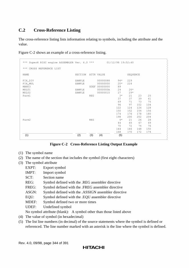
Rev. 4.0, 09/98, page 344 of 391
C.2 Cross-Reference Listing
The cross-reference listing lists information relating to symbols, including the attribute and thevalue.
Figure C-2 shows an example of a cross-reference listing.
*** SuperH RISC engine ASSEMBLER Ver. 4.0 *** 01/12/98 19:52:40
*** CROSS REFERENCE LIST
NAME SECTION ATTR VALUE SEQUENCE
FIX_DIV SAMPLE 00000088 94* 229FIX_MUL SAMPLE 00000000 20* 224MAN03 UDEF 00000000 89MUL01 SAMPLE 0000000A 24 26*MUL02 SAMPLE 00000010 27 29*Parm1 REG 3* 21 23 25 37 37 39 41 69 71 73 75 96 97 102 104 122 124 126 128 150 152 154 156 174 176 178 180 198 200 202 204Parm2 REG 4* 21 26 28 44 45 47 49 70 72 74 76 144 146 148 150 168 170 172 174
(1) (2) (3) (4) (5)
Figure C-2 Cross-Reference Listing Output Example
(1) The symbol name(2) The name of the section that includes the symbol (first eight characters)(3) The symbol attribute
EXPT: Export symbolIMPT: Import symbolSCT: Section nameREG: Symbol defined with the .REG assembler directiveFREG: Symbol defined with the .FREG assembler directiveASGN: Symbol defined with the .ASSIGN assembler directiveEQU: Symbol defined with the .EQU assembler directiveMDEF: Symbol defined two or more timesUDEF: Undefined symbolNo symbol attribute (blank): A symbol other than those listed above
(4) The value of symbol (in hexadecimal)(5) The list line numbers (in decimal) of the source statements where the symbol is defined or
referenced. The line number marked with an asterisk is the line where the symbol is defined.
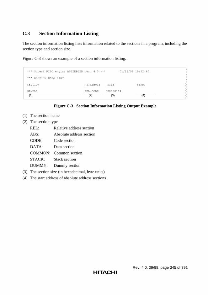
Rev. 4.0, 09/98, page 345 of 391
C.3 Section Information Listing
The section information listing lists information related to the sections in a program, including thesection type and section size.
Figure C-3 shows an example of a section information listing.
*** SuperH RISC engine ASSEMBLER Ver. 4.0 *** 01/12/98 19:52:40
*** SECTION DATA LIST
SECTION ATTRIBUTE SIZE START
SAMPLE REL-CODE 000000194
(1) (2) (3) (4)
Figure C-3 Section Information Listing Output Example
(1) The section name
(2) The section type
REL: Relative address section
ABS: Absolute address section
CODE: Code section
DATA: Data section
COMMON: Common section
STACK: Stack section
DUMMY: Dummy section
(3) The section size (in hexadecimal, byte units)
(4) The start address of absolute address sections
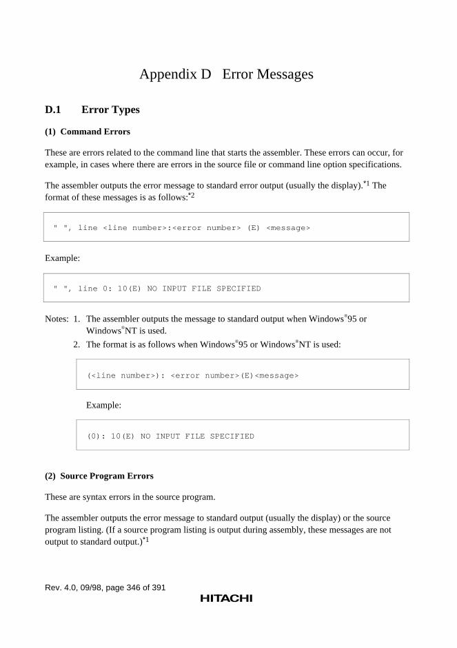
Rev. 4.0, 09/98, page 346 of 391
Appendix D Error Messages
D.1 Error Types
(1) Command Errors
These are errors related to the command line that starts the assembler. These errors can occur, forexample, in cases where there are errors in the source file or command line option specifications.
The assembler outputs the error message to standard error output (usually the display).*1 Theformat of these messages is as follows:*2
" ", line <line number>:<error number> (E) <message>
Example:
" ", line 0: 10(E) NO INPUT FILE SPECIFIED
Notes: 1. The assembler outputs the message to standard output when Windows®95 orWindows®NT is used.
2. The format is as follows when Windows®95 or Windows®NT is used:
(<line number>): <error number>(E)<message>
Example:
(0): 10(E) NO INPUT FILE SPECIFIED
(2) Source Program Errors
These are syntax errors in the source program.
The assembler outputs the error message to standard output (usually the display) or the sourceprogram listing. (If a source program listing is output during assembly, these messages are notoutput to standard output.)*1
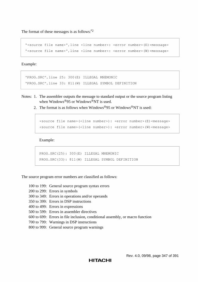
Rev. 4.0, 09/98, page 347 of 391
The format of these messages is as follows:*2
"<source file name>",line <line number>: <error number>(E)<message>
"<source file name>",line <line number>: <error number>(W)<message>
Example:
"PROG.SRC",line 25: 300(E) ILLEGAL MNEMONIC
"PROG.SRC",line 33: 811(W) ILLEGAL SYMBOL DEFINITION
Notes: 1. The assembler outputs the message to standard output or the source program listingwhen Windows®95 or Windows®NT is used.
2. The format is as follows when Windows®95 or Windows®NT is used:
<source file name>(<line number>): <error number>(E)<message>
<source file name>(<line number>): <error number>(W)<message>
Example:
PROG.SRC(25): 300(E) ILLEGAL MNEMONIC
PROG.SRC(33): 811(W) ILLEGAL SYMBOL DEFINITION
The source program error numbers are classified as follows:
100 to 199: General source program syntax errors200 to 299: Errors in symbols300 to 349: Errors in operations and/or operands350 to 399: Errors in DSP instructions400 to 499: Errors in expressions500 to 599: Errors in assembler directives600 to 699: Errors in file inclusion, conditional assembly, or macro function700 to 799: Warnings in DSP instructions800 to 999: General source program warnings
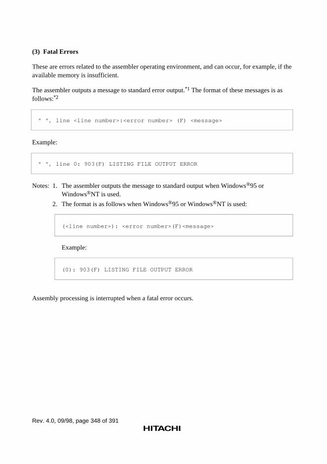
Rev. 4.0, 09/98, page 348 of 391
(3) Fatal Errors
These are errors related to the assembler operating environment, and can occur, for example, if theavailable memory is insufficient.
The assembler outputs a message to standard error output.*1 The format of these messages is asfollows:*2
" ", line <line number>:<error number> (F) <message>
Example:
" ", line 0: 903(F) LISTING FILE OUTPUT ERROR
Notes: 1. The assembler outputs the message to standard output when Windows®95 orWindows®NT is used.
2. The format is as follows when Windows®95 or Windows®NT is used:
(<line number>): <error number>(F)<message>
Example:
(0): 903(F) LISTING FILE OUTPUT ERROR
Assembly processing is interrupted when a fatal error occurs.
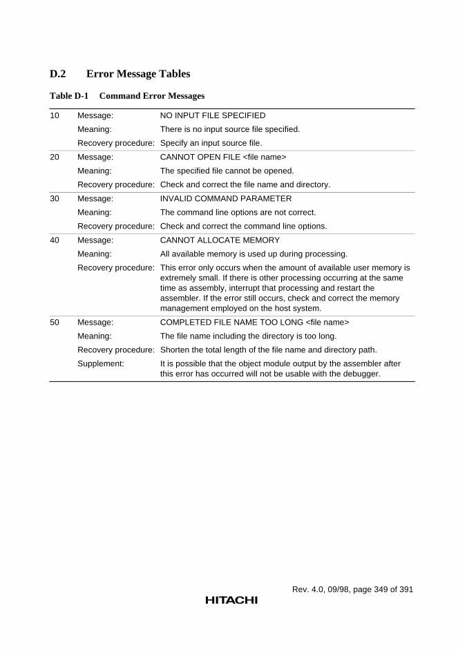
Rev. 4.0, 09/98, page 349 of 391
D.2 Error Message Tables
Table D-1 Command Error Messages
10 Message: NO INPUT FILE SPECIFIED
Meaning: There is no input source file specified.
Recovery procedure: Specify an input source file.
20 Message: CANNOT OPEN FILE <file name>
Meaning: The specified file cannot be opened.
Recovery procedure: Check and correct the file name and directory.
30 Message: INVALID COMMAND PARAMETER
Meaning: The command line options are not correct.
Recovery procedure: Check and correct the command line options.
40 Message: CANNOT ALLOCATE MEMORY
Meaning: All available memory is used up during processing.
Recovery procedure: This error only occurs when the amount of available user memory isextremely small. If there is other processing occurring at the sametime as assembly, interrupt that processing and restart theassembler. If the error still occurs, check and correct the memorymanagement employed on the host system.
50 Message: COMPLETED FILE NAME TOO LONG <file name>
Meaning: The file name including the directory is too long.
Recovery procedure: Shorten the total length of the file name and directory path.
Supplement: It is possible that the object module output by the assembler afterthis error has occurred will not be usable with the debugger.
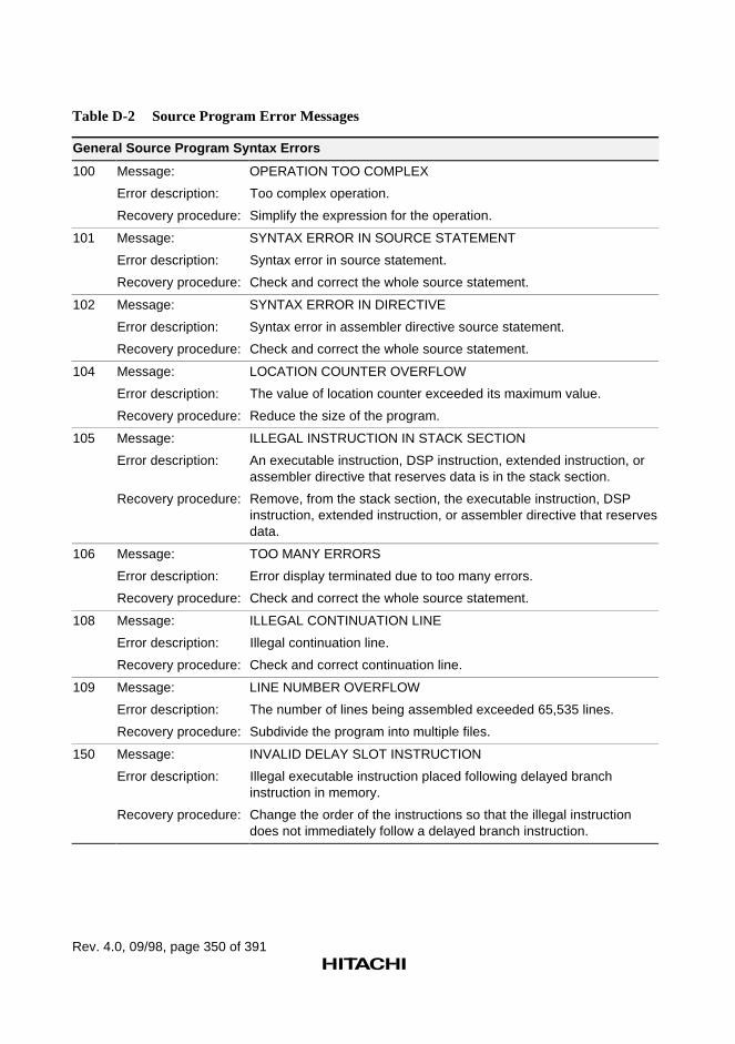
Rev. 4.0, 09/98, page 350 of 391
Table D-2 Source Program Error Messages
General Source Program Syntax Errors
100 Message: OPERATION TOO COMPLEX
Error description: Too complex operation.
Recovery procedure: Simplify the expression for the operation.
101 Message: SYNTAX ERROR IN SOURCE STATEMENT
Error description: Syntax error in source statement.
Recovery procedure: Check and correct the whole source statement.
102 Message: SYNTAX ERROR IN DIRECTIVE
Error description: Syntax error in assembler directive source statement.
Recovery procedure: Check and correct the whole source statement.
104 Message: LOCATION COUNTER OVERFLOW
Error description: The value of location counter exceeded its maximum value.
Recovery procedure: Reduce the size of the program.
105 Message: ILLEGAL INSTRUCTION IN STACK SECTION
Error description: An executable instruction, DSP instruction, extended instruction, orassembler directive that reserves data is in the stack section.
Recovery procedure: Remove, from the stack section, the executable instruction, DSPinstruction, extended instruction, or assembler directive that reservesdata.
106 Message: TOO MANY ERRORS
Error description: Error display terminated due to too many errors.
Recovery procedure: Check and correct the whole source statement.
108 Message: ILLEGAL CONTINUATION LINE
Error description: Illegal continuation line.
Recovery procedure: Check and correct continuation line.
109 Message: LINE NUMBER OVERFLOW
Error description: The number of lines being assembled exceeded 65,535 lines.
Recovery procedure: Subdivide the program into multiple files.
150 Message: INVALID DELAY SLOT INSTRUCTION
Error description: Illegal executable instruction placed following delayed branchinstruction in memory.
Recovery procedure: Change the order of the instructions so that the illegal instructiondoes not immediately follow a delayed branch instruction.
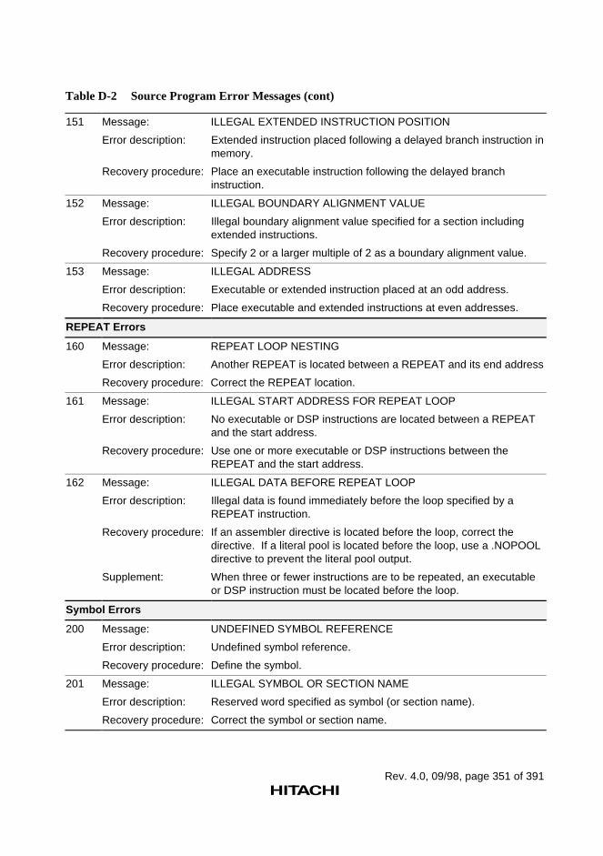
Rev. 4.0, 09/98, page 351 of 391
Table D-2 Source Program Error Messages (cont)
151 Message: ILLEGAL EXTENDED INSTRUCTION POSITION
Error description: Extended instruction placed following a delayed branch instruction inmemory.
Recovery procedure: Place an executable instruction following the delayed branchinstruction.
152 Message: ILLEGAL BOUNDARY ALIGNMENT VALUE
Error description: Illegal boundary alignment value specified for a section includingextended instructions.
Recovery procedure: Specify 2 or a larger multiple of 2 as a boundary alignment value.
153 Message: ILLEGAL ADDRESS
Error description: Executable or extended instruction placed at an odd address.
Recovery procedure: Place executable and extended instructions at even addresses.
REPEAT Errors
160 Message: REPEAT LOOP NESTING
Error description: Another REPEAT is located between a REPEAT and its end address
Recovery procedure: Correct the REPEAT location.
161 Message: ILLEGAL START ADDRESS FOR REPEAT LOOP
Error description: No executable or DSP instructions are located between a REPEATand the start address.
Recovery procedure: Use one or more executable or DSP instructions between theREPEAT and the start address.
162 Message: ILLEGAL DATA BEFORE REPEAT LOOP
Error description: Illegal data is found immediately before the loop specified by aREPEAT instruction.
Recovery procedure: If an assembler directive is located before the loop, correct thedirective. If a literal pool is located before the loop, use a .NOPOOLdirective to prevent the literal pool output.
Supplement: When three or fewer instructions are to be repeated, an executableor DSP instruction must be located before the loop.
Symbol Errors
200 Message: UNDEFINED SYMBOL REFERENCE
Error description: Undefined symbol reference.
Recovery procedure: Define the symbol.
201 Message: ILLEGAL SYMBOL OR SECTION NAME
Error description: Reserved word specified as symbol (or section name).
Recovery procedure: Correct the symbol or section name.
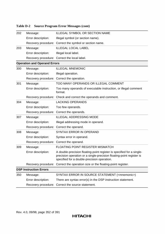
Rev. 4.0, 09/98, page 352 of 391
Table D-2 Source Program Error Messages (cont)
202 Message: ILLEGAL SYMBOL OR SECTION NAME
Error description: Illegal symbol (or section name).
Recovery procedure: Correct the symbol or section name.
203 Message: ILLEGAL LOCAL LABEL
Error description: Illegal local label.
Recovery procedure: Correct the local label.
Operation and Operand Errors
300 Message: ILLEGAL MNEMONIC
Error description: Illegal operation.
Recovery procedure: Correct the operation.
301 Message: TOO MANY OPERANDS OR ILLEGAL COMMENT
Error description: Too many operands of executable instruction, or illegal commentformat.
Recovery procedure: Check and correct the operands and comment.
304 Message: LACKING OPERANDS
Error description: Too few operands.
Recovery procedure: Correct the operands.
307 Message: ILLEGAL ADDRESSING MODE
Error description: Illegal addressing mode in operand.
Recovery procedure: Correct the operand.
308 Message: SYNTAX ERROR IN OPERAND
Error description: Syntax error in operand.
Recovery procedure: Correct the operand.
309 Message: FLOATING POINT REGISTER MISMATCH
Error description: A double-precision floating-point register is specified for a single-precision operation or a single-precision floating-point register isspecified for a double-precision operation.
Recovery procedure: Correct the operation size or the floating-point register.
DSP Instruction Errors
350 Message: SYNTAX ERROR IN SOURCE STATEMENT (<mnemonic>)
Error description: There are syntax error(s) in the DSP instruction statement.
Recovery procedure: Correct the source statement.
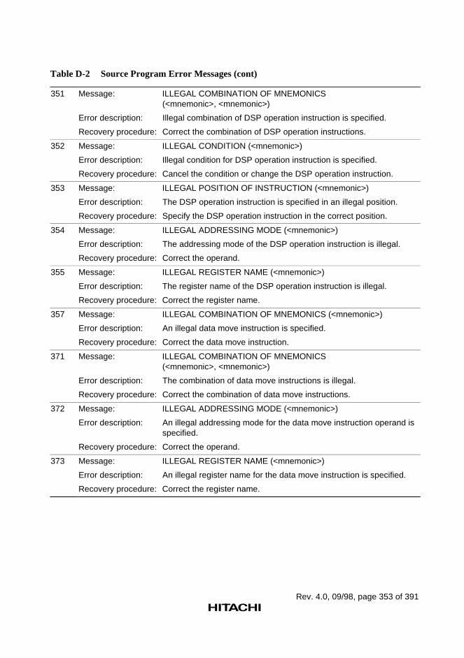
Rev. 4.0, 09/98, page 353 of 391
Table D-2 Source Program Error Messages (cont)
351 Message: ILLEGAL COMBINATION OF MNEMONICS(<mnemonic>, <mnemonic>)
Error description: Illegal combination of DSP operation instruction is specified.
Recovery procedure: Correct the combination of DSP operation instructions.
352 Message: ILLEGAL CONDITION (<mnemonic>)
Error description: Illegal condition for DSP operation instruction is specified.
Recovery procedure: Cancel the condition or change the DSP operation instruction.
353 Message: ILLEGAL POSITION OF INSTRUCTION (<mnemonic>)
Error description: The DSP operation instruction is specified in an illegal position.
Recovery procedure: Specify the DSP operation instruction in the correct position.
354 Message: ILLEGAL ADDRESSING MODE (<mnemonic>)
Error description: The addressing mode of the DSP operation instruction is illegal.
Recovery procedure: Correct the operand.
355 Message: ILLEGAL REGISTER NAME (<mnemonic>)
Error description: The register name of the DSP operation instruction is illegal.
Recovery procedure: Correct the register name.
357 Message: ILLEGAL COMBINATION OF MNEMONICS (<mnemonic>)
Error description: An illegal data move instruction is specified.
Recovery procedure: Correct the data move instruction.
371 Message: ILLEGAL COMBINATION OF MNEMONICS(<mnemonic>, <mnemonic>)
Error description: The combination of data move instructions is illegal.
Recovery procedure: Correct the combination of data move instructions.
372 Message: ILLEGAL ADDRESSING MODE (<mnemonic>)
Error description: An illegal addressing mode for the data move instruction operand isspecified.
Recovery procedure: Correct the operand.
373 Message: ILLEGAL REGISTER NAME (<mnemonic>)
Error description: An illegal register name for the data move instruction is specified.
Recovery procedure: Correct the register name.
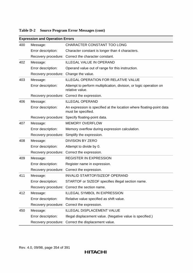
Rev. 4.0, 09/98, page 354 of 391
Table D-2 Source Program Error Messages (cont)
Expression and Operation Errors
400 Message: CHARACTER CONSTANT TOO LONG
Error description: Character constant is longer than 4 characters.
Recovery procedure: Correct the character constant.
402 Message: ILLEGAL VALUE IN OPERAND
Error description: Operand value out of range for this instruction.
Recovery procedure: Change the value.
403 Message: ILLEGAL OPERATION FOR RELATIVE VALUE
Error description: Attempt to perform multiplication, division, or logic operation onrelative value.
Recovery procedure: Correct the expression.
406 Message: ILLEGAL OPERAND
Error description: An expression is specified at the location where floating-point datamust be specified.
Recovery procedure: Specify floating-point data.
407 Message: MEMORY OVERFLOW
Error description: Memory overflow during expression calculation.
Recovery procedure: Simplify the expression.
408 Message: DIVISION BY ZERO
Error description: Attempt to divide by 0.
Recovery procedure: Correct the expression.
409 Message: REGISTER IN EXPRESSION
Error description: Register name in expression.
Recovery procedure: Correct the expression.
411 Message: INVALID STARTOF/SIZEOF OPERAND
Error description: STARTOF or SIZEOF specifies illegal section name.
Recovery procedure: Correct the section name.
412 Message: ILLEGAL SYMBOL IN EXPRESSION
Error description: Relative value specified as shift value.
Recovery procedure: Correct the expression.
450 Message: ILLEGAL DISPLACEMENT VALUE
Error description: Illegal displacement value. (Negative value is specified.)
Recovery procedure: Correct the displacement value.
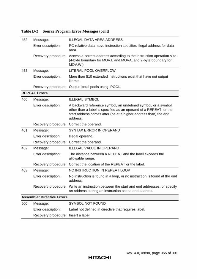
Rev. 4.0, 09/98, page 355 of 391
Table D-2 Source Program Error Messages (cont)
452 Message: ILLEGAL DATA AREA ADDRESS
Error description: PC-relative data move instruction specifies illegal address for dataarea.
Recovery procedure: Access a correct address according to the instruction operation size.(4-byte boundary for MOV.L and MOVA, and 2-byte boundary forMOV.W.)
453 Message: LITERAL POOL OVERFLOW
Error description: More than 510 extended instructions exist that have not outputliterals.
Recovery procedure: Output literal pools using .POOL.
REPEAT Errors
460 Message: ILLEGAL SYMBOL
Error description: A backward reference symbol, an undefined symbol, or a symbolother than a label is specified as an operand of a REPEAT, or thestart address comes after (be at a higher address than) the endaddress.
Recovery procedure: Correct the operand.
461 Message: SYNTAX ERROR IN OPERAND
Error description: Illegal operand.
Recovery procedure: Correct the operand.
462 Message: ILLEGAL VALUE IN OPERAND
Error description: The distance between a REPEAT and the label exceeds theallowable range.
Recovery procedure: Correct the location of the REPEAT or the label.
463 Message: NO INSTRUCTION IN REPEAT LOOP
Error description: No instruction is found in a loop, or no instruction is found at the endaddress.
Recovery procedure: Write an instruction between the start and end addresses, or specifyan address storing an instruction as the end address.
Assembler Directive Errors
500 Message: SYMBOL NOT FOUND
Error description: Label not defined in directive that requires label.
Recovery procedure: Insert a label.
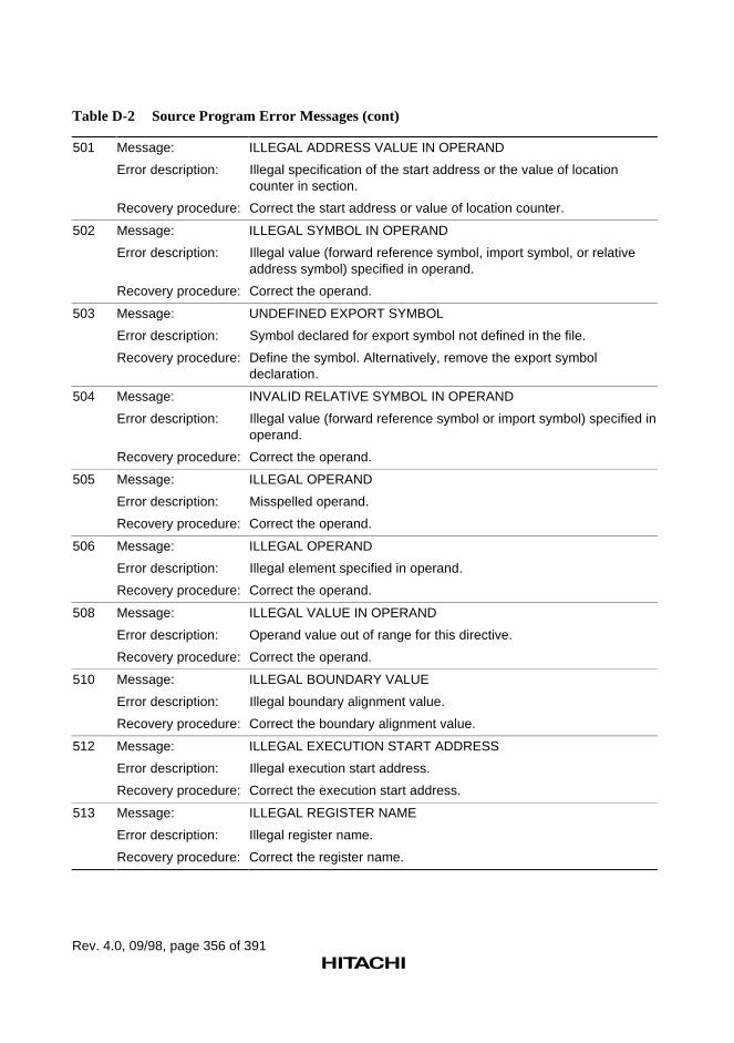
Rev. 4.0, 09/98, page 356 of 391
Table D-2 Source Program Error Messages (cont)
501 Message: ILLEGAL ADDRESS VALUE IN OPERAND
Error description: Illegal specification of the start address or the value of locationcounter in section.
Recovery procedure: Correct the start address or value of location counter.
502 Message: ILLEGAL SYMBOL IN OPERAND
Error description: Illegal value (forward reference symbol, import symbol, or relativeaddress symbol) specified in operand.
Recovery procedure: Correct the operand.
503 Message: UNDEFINED EXPORT SYMBOL
Error description: Symbol declared for export symbol not defined in the file.
Recovery procedure: Define the symbol. Alternatively, remove the export symboldeclaration.
504 Message: INVALID RELATIVE SYMBOL IN OPERAND
Error description: Illegal value (forward reference symbol or import symbol) specified inoperand.
Recovery procedure: Correct the operand.
505 Message: ILLEGAL OPERAND
Error description: Misspelled operand.
Recovery procedure: Correct the operand.
506 Message: ILLEGAL OPERAND
Error description: Illegal element specified in operand.
Recovery procedure: Correct the operand.
508 Message: ILLEGAL VALUE IN OPERAND
Error description: Operand value out of range for this directive.
Recovery procedure: Correct the operand.
510 Message: ILLEGAL BOUNDARY VALUE
Error description: Illegal boundary alignment value.
Recovery procedure: Correct the boundary alignment value.
512 Message: ILLEGAL EXECUTION START ADDRESS
Error description: Illegal execution start address.
Recovery procedure: Correct the execution start address.
513 Message: ILLEGAL REGISTER NAME
Error description: Illegal register name.
Recovery procedure: Correct the register name.
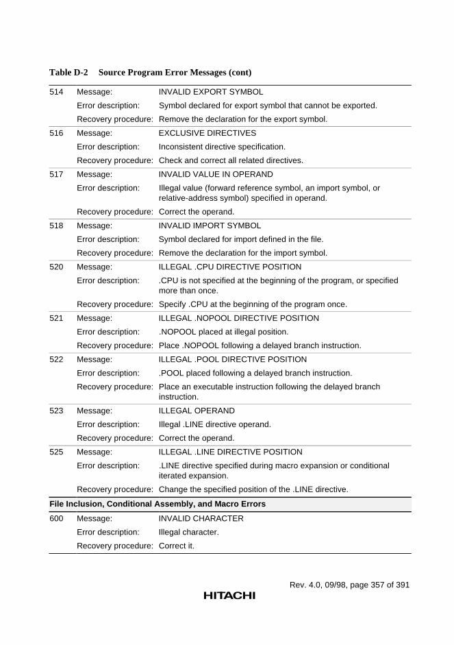
Rev. 4.0, 09/98, page 357 of 391
Table D-2 Source Program Error Messages (cont)
514 Message: INVALID EXPORT SYMBOL
Error description: Symbol declared for export symbol that cannot be exported.
Recovery procedure: Remove the declaration for the export symbol.
516 Message: EXCLUSIVE DIRECTIVES
Error description: Inconsistent directive specification.
Recovery procedure: Check and correct all related directives.
517 Message: INVALID VALUE IN OPERAND
Error description: Illegal value (forward reference symbol, an import symbol, orrelative-address symbol) specified in operand.
Recovery procedure: Correct the operand.
518 Message: INVALID IMPORT SYMBOL
Error description: Symbol declared for import defined in the file.
Recovery procedure: Remove the declaration for the import symbol.
520 Message: ILLEGAL .CPU DIRECTIVE POSITION
Error description: .CPU is not specified at the beginning of the program, or specifiedmore than once.
Recovery procedure: Specify .CPU at the beginning of the program once.
521 Message: ILLEGAL .NOPOOL DIRECTIVE POSITION
Error description: .NOPOOL placed at illegal position.
Recovery procedure: Place .NOPOOL following a delayed branch instruction.
522 Message: ILLEGAL .POOL DIRECTIVE POSITION
Error description: .POOL placed following a delayed branch instruction.
Recovery procedure: Place an executable instruction following the delayed branchinstruction.
523 Message: ILLEGAL OPERAND
Error description: Illegal .LINE directive operand.
Recovery procedure: Correct the operand.
525 Message: ILLEGAL .LINE DIRECTIVE POSITION
Error description: .LINE directive specified during macro expansion or conditionaliterated expansion.
Recovery procedure: Change the specified position of the .LINE directive.
File Inclusion, Conditional Assembly, and Macro Errors
600 Message: INVALID CHARACTER
Error description: Illegal character.
Recovery procedure: Correct it.
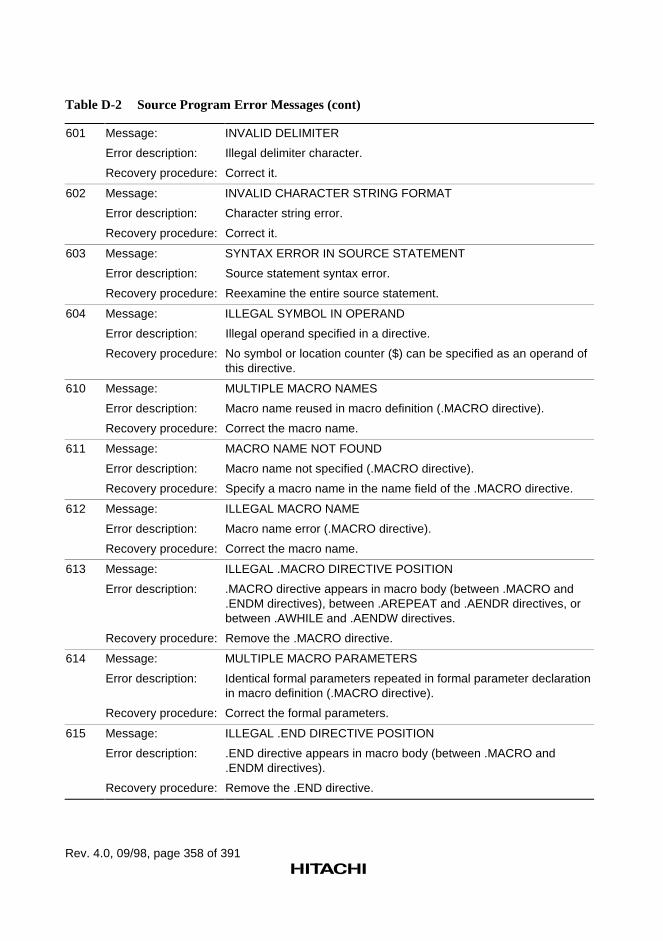
Rev. 4.0, 09/98, page 358 of 391
Table D-2 Source Program Error Messages (cont)
601 Message: INVALID DELIMITER
Error description: Illegal delimiter character.
Recovery procedure: Correct it.
602 Message: INVALID CHARACTER STRING FORMAT
Error description: Character string error.
Recovery procedure: Correct it.
603 Message: SYNTAX ERROR IN SOURCE STATEMENT
Error description: Source statement syntax error.
Recovery procedure: Reexamine the entire source statement.
604 Message: ILLEGAL SYMBOL IN OPERAND
Error description: Illegal operand specified in a directive.
Recovery procedure: No symbol or location counter ($) can be specified as an operand ofthis directive.
610 Message: MULTIPLE MACRO NAMES
Error description: Macro name reused in macro definition (.MACRO directive).
Recovery procedure: Correct the macro name.
611 Message: MACRO NAME NOT FOUND
Error description: Macro name not specified (.MACRO directive).
Recovery procedure: Specify a macro name in the name field of the .MACRO directive.
612 Message: ILLEGAL MACRO NAME
Error description: Macro name error (.MACRO directive).
Recovery procedure: Correct the macro name.
613 Message: ILLEGAL .MACRO DIRECTIVE POSITION
Error description: .MACRO directive appears in macro body (between .MACRO and.ENDM directives), between .AREPEAT and .AENDR directives, orbetween .AWHILE and .AENDW directives.
Recovery procedure: Remove the .MACRO directive.
614 Message: MULTIPLE MACRO PARAMETERS
Error description: Identical formal parameters repeated in formal parameter declarationin macro definition (.MACRO directive).
Recovery procedure: Correct the formal parameters.
615 Message: ILLEGAL .END DIRECTIVE POSITION
Error description: .END directive appears in macro body (between .MACRO and.ENDM directives).
Recovery procedure: Remove the .END directive.
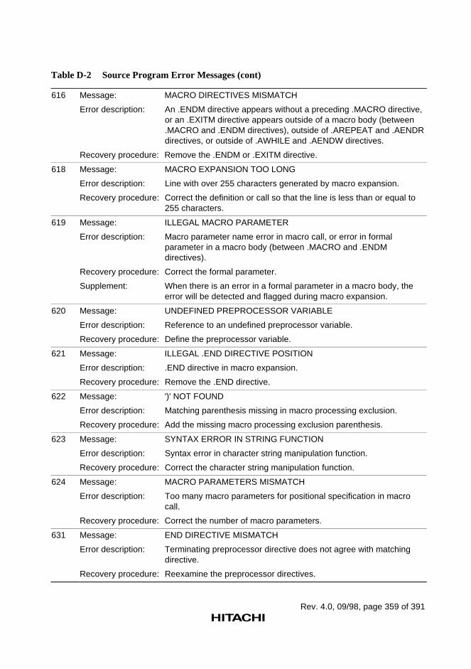
Rev. 4.0, 09/98, page 359 of 391
Table D-2 Source Program Error Messages (cont)
616 Message: MACRO DIRECTIVES MISMATCH
Error description: An .ENDM directive appears without a preceding .MACRO directive,or an .EXITM directive appears outside of a macro body (between.MACRO and .ENDM directives), outside of .AREPEAT and .AENDRdirectives, or outside of .AWHILE and .AENDW directives.
Recovery procedure: Remove the .ENDM or .EXITM directive.
618 Message: MACRO EXPANSION TOO LONG
Error description: Line with over 255 characters generated by macro expansion.
Recovery procedure: Correct the definition or call so that the line is less than or equal to255 characters.
619 Message: ILLEGAL MACRO PARAMETER
Error description: Macro parameter name error in macro call, or error in formalparameter in a macro body (between .MACRO and .ENDMdirectives).
Recovery procedure: Correct the formal parameter.
Supplement: When there is an error in a formal parameter in a macro body, theerror will be detected and flagged during macro expansion.
620 Message: UNDEFINED PREPROCESSOR VARIABLE
Error description: Reference to an undefined preprocessor variable.
Recovery procedure: Define the preprocessor variable.
621 Message: ILLEGAL .END DIRECTIVE POSITION
Error description: .END directive in macro expansion.
Recovery procedure: Remove the .END directive.
622 Message: ')' NOT FOUND
Error description: Matching parenthesis missing in macro processing exclusion.
Recovery procedure: Add the missing macro processing exclusion parenthesis.
623 Message: SYNTAX ERROR IN STRING FUNCTION
Error description: Syntax error in character string manipulation function.
Recovery procedure: Correct the character string manipulation function.
624 Message: MACRO PARAMETERS MISMATCH
Error description: Too many macro parameters for positional specification in macrocall.
Recovery procedure: Correct the number of macro parameters.
631 Message: END DIRECTIVE MISMATCH
Error description: Terminating preprocessor directive does not agree with matchingdirective.
Recovery procedure: Reexamine the preprocessor directives.
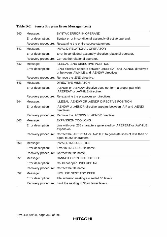
Rev. 4.0, 09/98, page 360 of 391
Table D-2 Source Program Error Messages (cont)
640 Message: SYNTAX ERROR IN OPERAND
Error description: Syntax error in conditional assembly directive operand.
Recovery procedure: Reexamine the entire source statement.
641 Message: INVALID RELATIONAL OPERATOR
Error description: Error in conditional assembly directive relational operator.
Recovery procedure: Correct the relational operator.
642 Message: ILLEGAL .END DIRECTIVE POSITION
Error description: .END directive appears between .AREPEAT and .AENDR directivesor between .AWHILE and .AENDW directives.
Recovery procedure: Remove the .END directive.
643 Message: DIRECTIVE MISMATCH
Error description: .AENDR or .AENDW directive does not form a proper pair with.AREPEAT or .AWHILE directive.
Recovery procedure: Re-examine the preprocessor directives.
644 Message: ILLEGAL .AENDW OR .AENDR DIRECTIVE POSITION
Error description: .AENDW or .AENDR directive appears between .AIF and .AENDIdirectives.
Recovery procedure: Remove the .AENDW or .AENDR directive.
645 Message: EXPANSION TOO LONG
Error description: Line with over 255 characters generated by .AREPEAT or .AWHILEexpansion.
Recovery procedure: Correct the .AREPEAT or .AWHILE to generate lines of less than orequal to 255 characters.
650 Message: INVALID INCLUDE FILE
Error description: Error in .INCLUDE file name.
Recovery procedure: Correct the file name.
651 Message: CANNOT OPEN INCLUDE FILE
Error description: Could not open .INCLUDE file.
Recovery procedure: Correct the file name.
652 Message: INCLUDE NEST TOO DEEP
Error description: File inclusion nesting exceeded 30 levels.
Recovery procedure: Limit the nesting to 30 or fewer levels.
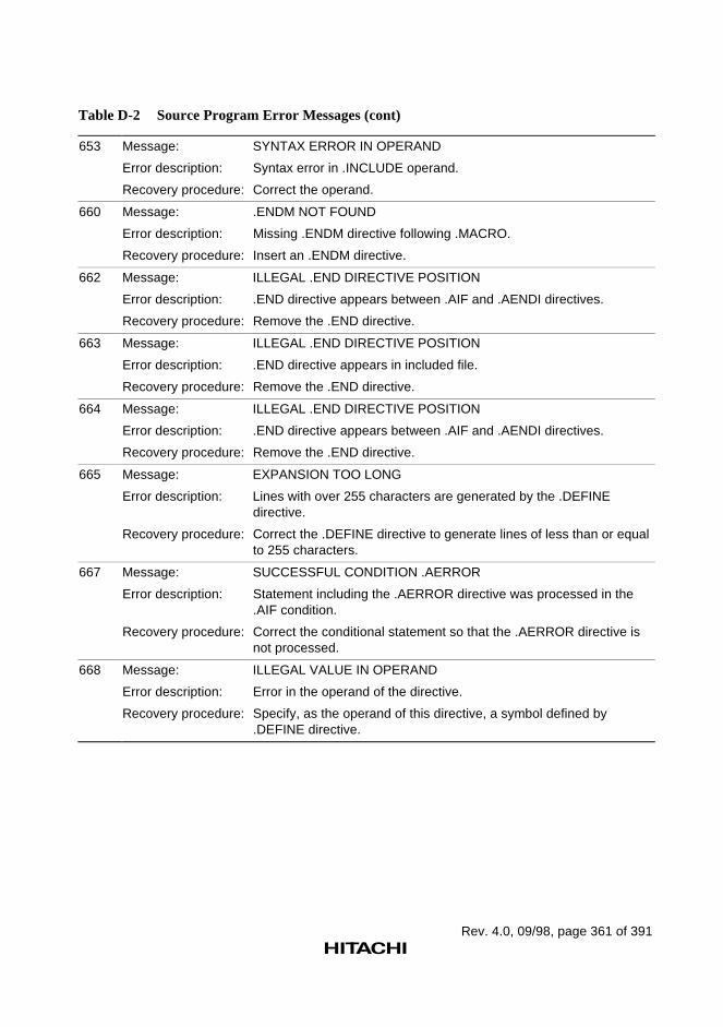
Rev. 4.0, 09/98, page 361 of 391
Table D-2 Source Program Error Messages (cont)
653 Message: SYNTAX ERROR IN OPERAND
Error description: Syntax error in .INCLUDE operand.
Recovery procedure: Correct the operand.
660 Message: .ENDM NOT FOUND
Error description: Missing .ENDM directive following .MACRO.
Recovery procedure: Insert an .ENDM directive.
662 Message: ILLEGAL .END DIRECTIVE POSITION
Error description: .END directive appears between .AIF and .AENDI directives.
Recovery procedure: Remove the .END directive.
663 Message: ILLEGAL .END DIRECTIVE POSITION
Error description: .END directive appears in included file.
Recovery procedure: Remove the .END directive.
664 Message: ILLEGAL .END DIRECTIVE POSITION
Error description: .END directive appears between .AIF and .AENDI directives.
Recovery procedure: Remove the .END directive.
665 Message: EXPANSION TOO LONG
Error description: Lines with over 255 characters are generated by the .DEFINEdirective.
Recovery procedure: Correct the .DEFINE directive to generate lines of less than or equalto 255 characters.
667 Message: SUCCESSFUL CONDITION .AERROR
Error description: Statement including the .AERROR directive was processed in the.AIF condition.
Recovery procedure: Correct the conditional statement so that the .AERROR directive isnot processed.
668 Message: ILLEGAL VALUE IN OPERAND
Error description: Error in the operand of the directive.
Recovery procedure: Specify, as the operand of this directive, a symbol defined by.DEFINE directive.
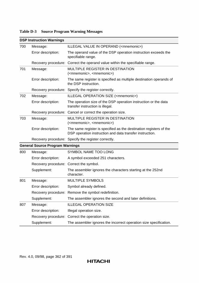
Rev. 4.0, 09/98, page 362 of 391
Table D-3 Source Program Warning Messages
DSP Instruction Warnings
700 Message: ILLEGAL VALUE IN OPERAND (<mnemonic>)
Error description: The operand value of the DSP operation instruction exceeds thespecifiable range.
Recovery procedure: Correct the operand value within the specifiable range.
701 Message: MULTIPLE REGISTER IN DESTINATION(<mnemonic>, <mnemonic>)
Error description: The same register is specified as multiple destination operands ofthe DSP instruction.
Recovery procedure: Specify the register correctly.
702 Message: ILLEGAL OPERATION SIZE (<mnemonic>)
Error description: The operation size of the DSP operation instruction or the datatransfer instruction is illegal.
Recovery procedure: Cancel or correct the operation size.
703 Message: MULTIPLE REGISTER IN DESTINATION(<mnemonic>, <mnemonic>)
Error description: The same register is specified as the destination registers of theDSP operation instruction and data transfer instruction.
Recovery procedure: Specify the register correctly.
General Source Program Warnings
800 Message: SYMBOL NAME TOO LONG
Error description: A symbol exceeded 251 characters.
Recovery procedure: Correct the symbol.
Supplement: The assembler ignores the characters starting at the 252ndcharacter.
801 Message: MULTIPLE SYMBOLS
Error description: Symbol already defined.
Recovery procedure: Remove the symbol redefinition.
Supplement: The assembler ignores the second and later definitions.
807 Message: ILLEGAL OPERATION SIZE
Error description: Illegal operation size.
Recovery procedure: Correct the operation size.
Supplement: The assembler ignores the incorrect operation size specification.
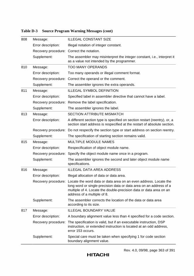
Rev. 4.0, 09/98, page 363 of 391
Table D-3 Source Program Warning Messages (cont)
808 Message: ILLEGAL CONSTANT SIZE
Error description: Illegal notation of integer constant.
Recovery procedure: Correct the notation.
Supplement: The assembler may misinterpret the integer constant, i.e., interpret itas a value not intended by the programmer.
810 Message: TOO MANY OPERANDS
Error description: Too many operands or illegal comment format.
Recovery procedure: Correct the operand or the comment.
Supplement: The assembler ignores the extra operands.
811 Message: ILLEGAL SYMBOL DEFINITION
Error description: Specified label in assembler directive that cannot have a label.
Recovery procedure: Remove the label specification.
Supplement: The assembler ignores the label.
813 Message: SECTION ATTRIBUTE MISMATCH
Error description: A different section type is specified on section restart (reentry), or, asection start address is respecified at the restart of absolute section.
Recovery procedure: Do not respecify the section type or start address on section reentry.
Supplement: The specification of starting section remains valid.
815 Message: MULTIPLE MODULE NAMES
Error description: Respecification of object module name.
Recovery procedure: Specify the object module name once in a program.
Supplement: The assembler ignores the second and later object module namespecifications.
816 Message: ILLEGAL DATA AREA ADDRESS
Error description: Illegal allocation of data or data area.
Recovery procedure: Locate the word data or data area on an even address. Locate thelong word or single-precision data or data area on an address of amultiple of 4. Locate the double-precision data or data area on anaddress of a multiple of 8.
Supplement: The assembler corrects the location of the data or data areaaccording to its size.
817 Message: ILLEGAL BOUNDARY VALUE
Error description: A boundary alignment value less than 4 specified for a code section.
Recovery procedure: The specification is valid, but if an executable instruction, DSPinstruction, or extended instruction is located at an odd address,error 153 occurs.
Supplement: Special care must be taken when specifying 1 for code sectionboundary alignment value.
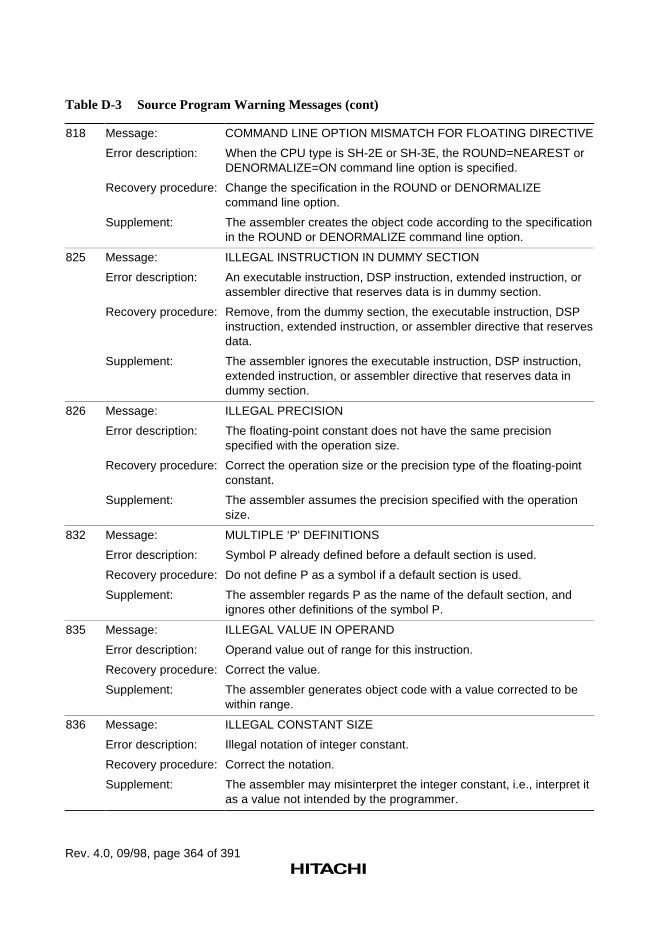
Rev. 4.0, 09/98, page 364 of 391
Table D-3 Source Program Warning Messages (cont)
818 Message: COMMAND LINE OPTION MISMATCH FOR FLOATING DIRECTIVE
Error description: When the CPU type is SH-2E or SH-3E, the ROUND=NEAREST orDENORMALIZE=ON command line option is specified.
Recovery procedure: Change the specification in the ROUND or DENORMALIZEcommand line option.
Supplement: The assembler creates the object code according to the specificationin the ROUND or DENORMALIZE command line option.
825 Message: ILLEGAL INSTRUCTION IN DUMMY SECTION
Error description: An executable instruction, DSP instruction, extended instruction, orassembler directive that reserves data is in dummy section.
Recovery procedure: Remove, from the dummy section, the executable instruction, DSPinstruction, extended instruction, or assembler directive that reservesdata.
Supplement: The assembler ignores the executable instruction, DSP instruction,extended instruction, or assembler directive that reserves data indummy section.
826 Message: ILLEGAL PRECISION
Error description: The floating-point constant does not have the same precisionspecified with the operation size.
Recovery procedure: Correct the operation size or the precision type of the floating-pointconstant.
Supplement: The assembler assumes the precision specified with the operationsize.
832 Message: MULTIPLE ‘P' DEFINITIONS
Error description: Symbol P already defined before a default section is used.
Recovery procedure: Do not define P as a symbol if a default section is used.
Supplement: The assembler regards P as the name of the default section, andignores other definitions of the symbol P.
835 Message: ILLEGAL VALUE IN OPERAND
Error description: Operand value out of range for this instruction.
Recovery procedure: Correct the value.
Supplement: The assembler generates object code with a value corrected to bewithin range.
836 Message: ILLEGAL CONSTANT SIZE
Error description: Illegal notation of integer constant.
Recovery procedure: Correct the notation.
Supplement: The assembler may misinterpret the integer constant, i.e., interpret itas a value not intended by the programmer.
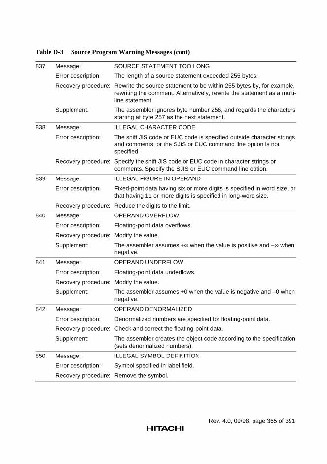
Rev. 4.0, 09/98, page 365 of 391
Table D-3 Source Program Warning Messages (cont)
837 Message: SOURCE STATEMENT TOO LONG
Error description: The length of a source statement exceeded 255 bytes.
Recovery procedure: Rewrite the source statement to be within 255 bytes by, for example,rewriting the comment. Alternatively, rewrite the statement as a multi-line statement.
Supplement: The assembler ignores byte number 256, and regards the charactersstarting at byte 257 as the next statement.
838 Message: ILLEGAL CHARACTER CODE
Error description: The shift JIS code or EUC code is specified outside character stringsand comments, or the SJIS or EUC command line option is notspecified.
Recovery procedure: Specify the shift JIS code or EUC code in character strings orcomments. Specify the SJIS or EUC command line option.
839 Message: ILLEGAL FIGURE IN OPERAND
Error description: Fixed-point data having six or more digits is specified in word size, orthat having 11 or more digits is specified in long-word size.
Recovery procedure: Reduce the digits to the limit.
840 Message: OPERAND OVERFLOW
Error description: Floating-point data overflows.
Recovery procedure: Modify the value.
Supplement: The assembler assumes +∞ when the value is positive and –∞ whennegative.
841 Message: OPERAND UNDERFLOW
Error description: Floating-point data underflows.
Recovery procedure: Modify the value.
Supplement: The assembler assumes +0 when the value is negative and –0 whennegative.
842 Message: OPERAND DENORMALIZED
Error description: Denormalized numbers are specified for floating-point data.
Recovery procedure: Check and correct the floating-point data.
Supplement: The assembler creates the object code according to the specification(sets denormalized numbers).
850 Message: ILLEGAL SYMBOL DEFINITION
Error description: Symbol specified in label field.
Recovery procedure: Remove the symbol.
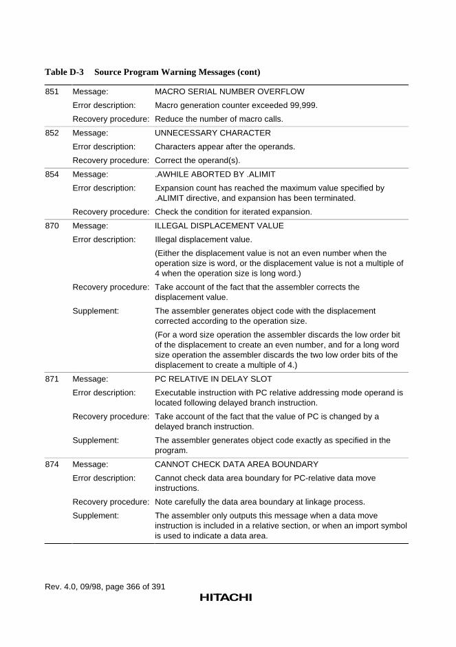
Rev. 4.0, 09/98, page 366 of 391
Table D-3 Source Program Warning Messages (cont)
851 Message: MACRO SERIAL NUMBER OVERFLOW
Error description: Macro generation counter exceeded 99,999.
Recovery procedure: Reduce the number of macro calls.
852 Message: UNNECESSARY CHARACTER
Error description: Characters appear after the operands.
Recovery procedure: Correct the operand(s).
854 Message: .AWHILE ABORTED BY .ALIMIT
Error description: Expansion count has reached the maximum value specified by.ALIMIT directive, and expansion has been terminated.
Recovery procedure: Check the condition for iterated expansion.
870 Message: ILLEGAL DISPLACEMENT VALUE
Error description: Illegal displacement value.
(Either the displacement value is not an even number when theoperation size is word, or the displacement value is not a multiple of4 when the operation size is long word.)
Recovery procedure: Take account of the fact that the assembler corrects thedisplacement value.
Supplement: The assembler generates object code with the displacementcorrected according to the operation size.
(For a word size operation the assembler discards the low order bitof the displacement to create an even number, and for a long wordsize operation the assembler discards the two low order bits of thedisplacement to create a multiple of 4.)
871 Message: PC RELATIVE IN DELAY SLOT
Error description: Executable instruction with PC relative addressing mode operand islocated following delayed branch instruction.
Recovery procedure: Take account of the fact that the value of PC is changed by adelayed branch instruction.
Supplement: The assembler generates object code exactly as specified in theprogram.
874 Message: CANNOT CHECK DATA AREA BOUNDARY
Error description: Cannot check data area boundary for PC-relative data moveinstructions.
Recovery procedure: Note carefully the data area boundary at linkage process.
Supplement: The assembler only outputs this message when a data moveinstruction is included in a relative section, or when an import symbolis used to indicate a data area.
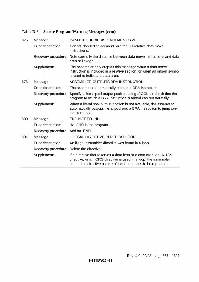
Rev. 4.0, 09/98, page 367 of 391
Table D-3 Source Program Warning Messages (cont)
875 Message: CANNOT CHECK DISPLACEMENT SIZE
Error description: Cannot check displacement size for PC-relative data moveinstructions.
Recovery procedure: Note carefully the distance between data move instructions and dataarea at linkage.
Supplement: The assembler only outputs this message when a data moveinstruction is included in a relative section, or when an import symbolis used to indicate a data area.
876 Message: ASSEMBLER OUTPUTS BRA INSTRUCTION
Error description: The assembler automatically outputs a BRA instruction.
Recovery procedure: Specify a literal pool output position using .POOL, or check that theprogram to which a BRA instruction is added can run normally.
Supplement: When a literal pool output location is not available, the assemblerautomatically outputs literal pool and a BRA instruction to jump overthe literal pool.
880 Message: END NOT FOUND
Error description: No .END in the program.
Recovery procedure: Add an .END.
881 Message: ILLEGAL DIRECTIVE IN REPEAT LOOP
Error description: An illegal assembler directive was found in a loop.
Recovery procedure: Delete the directive.
Supplement: If a directive that reserves a data item or a data area, an .ALIGNdirective, or an .ORG directive is used in a loop, the assemblercounts the directive as one of the instructions to be repeated.
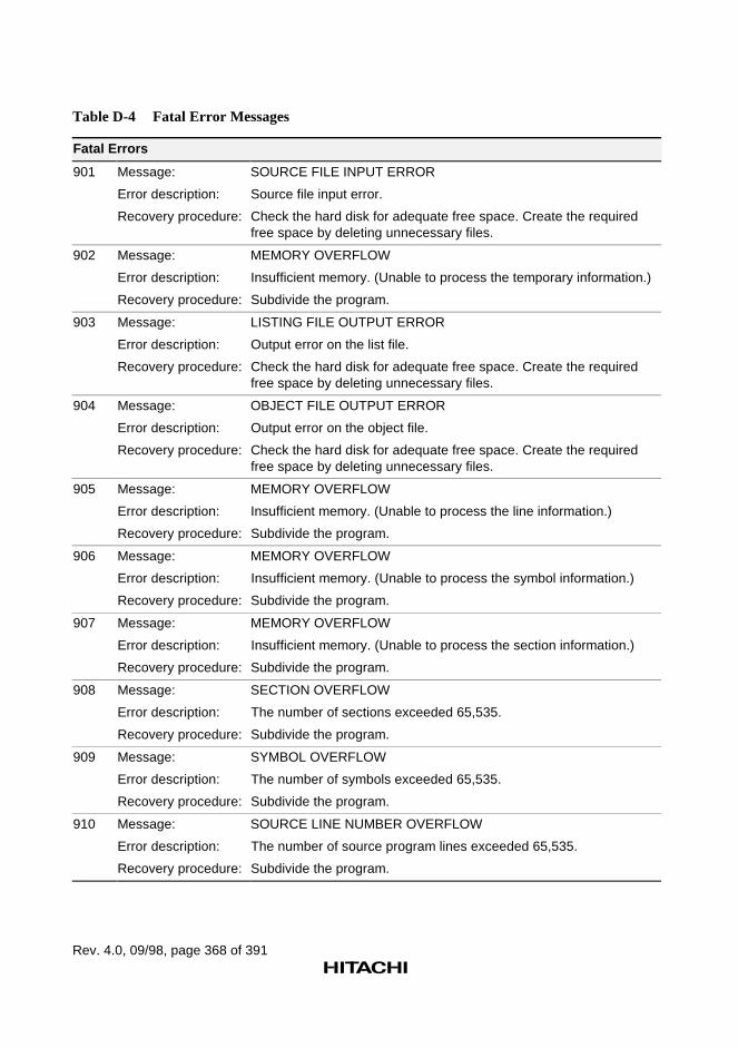
Rev. 4.0, 09/98, page 368 of 391
Table D-4 Fatal Error Messages
Fatal Errors
901 Message: SOURCE FILE INPUT ERROR
Error description: Source file input error.
Recovery procedure: Check the hard disk for adequate free space. Create the requiredfree space by deleting unnecessary files.
902 Message: MEMORY OVERFLOW
Error description: Insufficient memory. (Unable to process the temporary information.)
Recovery procedure: Subdivide the program.
903 Message: LISTING FILE OUTPUT ERROR
Error description: Output error on the list file.
Recovery procedure: Check the hard disk for adequate free space. Create the requiredfree space by deleting unnecessary files.
904 Message: OBJECT FILE OUTPUT ERROR
Error description: Output error on the object file.
Recovery procedure: Check the hard disk for adequate free space. Create the requiredfree space by deleting unnecessary files.
905 Message: MEMORY OVERFLOW
Error description: Insufficient memory. (Unable to process the line information.)
Recovery procedure: Subdivide the program.
906 Message: MEMORY OVERFLOW
Error description: Insufficient memory. (Unable to process the symbol information.)
Recovery procedure: Subdivide the program.
907 Message: MEMORY OVERFLOW
Error description: Insufficient memory. (Unable to process the section information.)
Recovery procedure: Subdivide the program.
908 Message: SECTION OVERFLOW
Error description: The number of sections exceeded 65,535.
Recovery procedure: Subdivide the program.
909 Message: SYMBOL OVERFLOW
Error description: The number of symbols exceeded 65,535.
Recovery procedure: Subdivide the program.
910 Message: SOURCE LINE NUMBER OVERFLOW
Error description: The number of source program lines exceeded 65,535.
Recovery procedure: Subdivide the program.
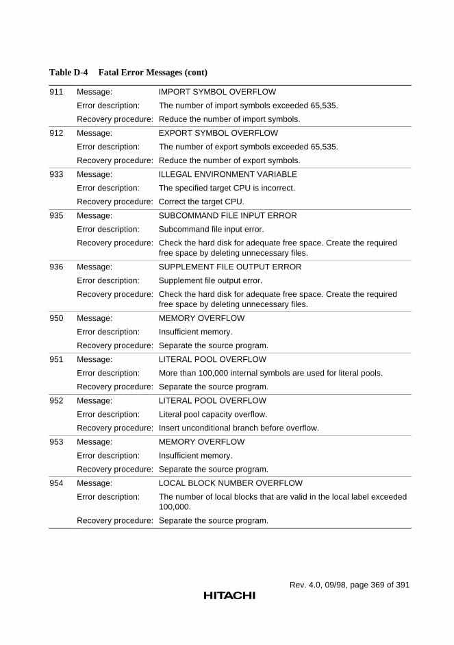
Rev. 4.0, 09/98, page 369 of 391
Table D-4 Fatal Error Messages (cont)
911 Message: IMPORT SYMBOL OVERFLOW
Error description: The number of import symbols exceeded 65,535.
Recovery procedure: Reduce the number of import symbols.
912 Message: EXPORT SYMBOL OVERFLOW
Error description: The number of export symbols exceeded 65,535.
Recovery procedure: Reduce the number of export symbols.
933 Message: ILLEGAL ENVIRONMENT VARIABLE
Error description: The specified target CPU is incorrect.
Recovery procedure: Correct the target CPU.
935 Message: SUBCOMMAND FILE INPUT ERROR
Error description: Subcommand file input error.
Recovery procedure: Check the hard disk for adequate free space. Create the requiredfree space by deleting unnecessary files.
936 Message: SUPPLEMENT FILE OUTPUT ERROR
Error description: Supplement file output error.
Recovery procedure: Check the hard disk for adequate free space. Create the requiredfree space by deleting unnecessary files.
950 Message: MEMORY OVERFLOW
Error description: Insufficient memory.
Recovery procedure: Separate the source program.
951 Message: LITERAL POOL OVERFLOW
Error description: More than 100,000 internal symbols are used for literal pools.
Recovery procedure: Separate the source program.
952 Message: LITERAL POOL OVERFLOW
Error description: Literal pool capacity overflow.
Recovery procedure: Insert unconditional branch before overflow.
953 Message: MEMORY OVERFLOW
Error description: Insufficient memory.
Recovery procedure: Separate the source program.
954 Message: LOCAL BLOCK NUMBER OVERFLOW
Error description: The number of local blocks that are valid in the local label exceeded100,000.
Recovery procedure: Separate the source program.
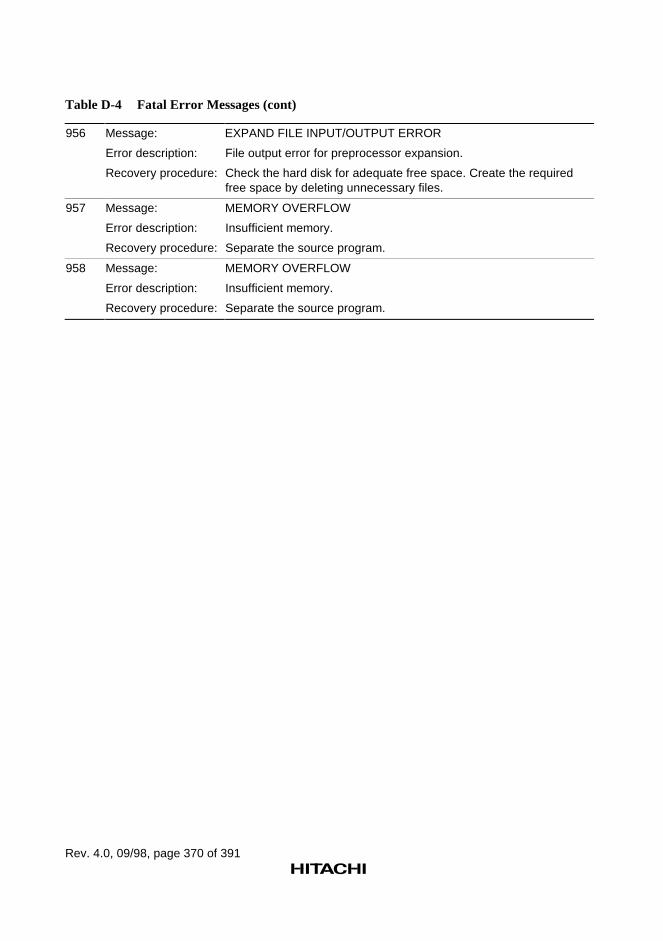
Rev. 4.0, 09/98, page 370 of 391
Table D-4 Fatal Error Messages (cont)
956 Message: EXPAND FILE INPUT/OUTPUT ERROR
Error description: File output error for preprocessor expansion.
Recovery procedure: Check the hard disk for adequate free space. Create the requiredfree space by deleting unnecessary files.
957 Message: MEMORY OVERFLOW
Error description: Insufficient memory.
Recovery procedure: Separate the source program.
958 Message: MEMORY OVERFLOW
Error description: Insufficient memory.
Recovery procedure: Separate the source program.
Rev. 4.0, 09/98, page 371 of 391
Appendix E Differences from Version 3.1
The differences between this new version (V.4.0) and the former version (V.3.1) are describedbelow.
E.1 CPU
This version includes assembly functions for the SH-2E, SH-4, and SH3-DSP in addition to theSH-1, SH-2, SH-3, SH-3E, and SH-DSP, and the following items are added or changed.
• Reserved words
• Executable instructions
• .CPU assembler directive
• CPU command line option
• SHCPU environment variable
References:
Reserved words→ Programmer's Guide, 1.2, "Reserved Words"
Executable instructions→ Programmer's Guide, 3, "Executable Instructions"
.CPU assembler directive→ Programmer's Guide, 5.2.1, "Assembler Directive Related to CPU"
–CPU command line option→ User's Guide, 2.2.1, "Target CPU Command Line Option"
SHCPU environment variable→ User's Guide, 1.3, "SHCPU Environment Variable"
E.2 Object Format
In the new version, ELF/DWARF object format is supported in addition to those supported in theformer version.
The assembler outputs ELF/DWARF supplement information when outputting debug information.
References:
Debug information→ Programmer's Guide, 5.2.6, "Object Module Assembler Directives", .OUTPUT→ User's Guide, 2.2.2, "Object Module Command Line Options", –DEBUG
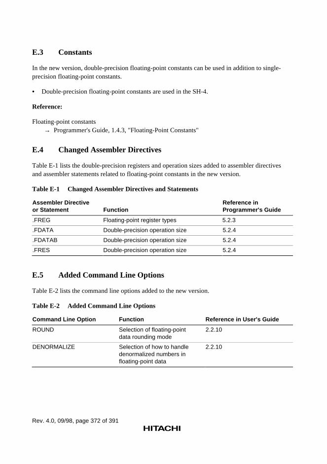
Rev. 4.0, 09/98, page 372 of 391
E.3 Constants
In the new version, double-precision floating-point constants can be used in addition to single-precision floating-point constants.
• Double-precision floating-point constants are used in the SH-4.
Reference:
Floating-point constants→ Programmer's Guide, 1.4.3, "Floating-Point Constants"
E.4 Changed Assembler Directives
Table E-1 lists the double-precision registers and operation sizes added to assembler directivesand assembler statements related to floating-point constants in the new version.
Table E-1 Changed Assembler Directives and Statements
Assembler Directiveor Statement Function
Reference inProgrammer's Guide
.FREG Floating-point register types 5.2.3
.FDATA Double-precision operation size 5.2.4
.FDATAB Double-precision operation size 5.2.4
.FRES Double-precision operation size 5.2.4
E.5 Added Command Line Options
Table E-2 lists the command line options added to the new version.
Table E-2 Added Command Line Options
Command Line Option Function Reference in User's Guide
ROUND Selection of floating-pointdata rounding mode
2.2.10
DENORMALIZE Selection of how to handledenormalized numbers infloating-point data
2.2.10
Rev. 4.0, 09/98, page 373 of 391
Reference:
Floating-point constants→ Programmer's Guide, 1.4.3, "Floating-Point Constants"
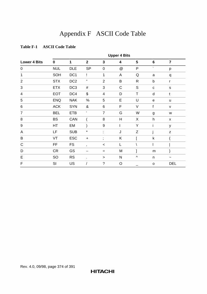
Rev. 4.0, 09/98, page 374 of 391
Appendix F ASCII Code Table
Table F-1 ASCII Code Table
Upper 4 Bits
Lower 4 Bits 0 1 2 3 4 5 6 7
0 NUL DLE SP 0 @ P ` p
1 SOH DC1 ! 1 A Q a q
2 STX DC2 ” 2 B R b r
3 ETX DC3 # 3 C S c s
4 EOT DC4 $ 4 D T d t
5 ENQ NAK % 5 E U e u
6 ACK SYN & 6 F V f v
7 BEL ETB ’ 7 G W g w
8 BS CAN ( 8 H X h x
9 HT EM ) 9 I Y i y
A LF SUB * : J Z j z
B VT ESC + ; K [ k {
C FF FS , < L \ l |
D CR GS – = M ] m }
E SO RS . > N ^ n ~
F SI US / ? O _ o DEL
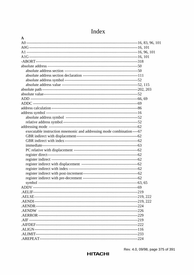
Rev. 4.0, 09/98, page 375 of 391
IndexAA0 -------------------------------------------------------------------------------------16, 83, 96, 101A0G -----------------------------------------------------------------------------------16, 101A1 -------------------------------------------------------------------------------------16, 96, 101A1G -----------------------------------------------------------------------------------16, 101-ABORT------------------------------------------------------------------------------318absolute address ---------------------------------------------------------------------50
absolute address section --------------------------------------------------------50absolute address section declaration ------------------------------------------111absolute address symbol --------------------------------------------------------52absolute address value ----------------------------------------------------------52, 115
absolute path -------------------------------------------------------------------------202, 203absolute value------------------------------------------------------------------------52ADD ----------------------------------------------------------------------------------66, 69ADDC --------------------------------------------------------------------------------69address calculation ------------------------------------------------------------------86address symbol ----------------------------------------------------------------------16
absolute address symbol -------------------------------------------------------52relative address symbol ---------------------------------------------------------52
addressing mode --------------------------------------------------------------------62executable instruction mnemonic and addressing mode combination ----67GBR indirect with displacement-----------------------------------------------62GBR indirect with index--------------------------------------------------------62immediate-------------------------------------------------------------------------63PC relative with displacement -------------------------------------------------62register direct---------------------------------------------------------------------62register indirect ------------------------------------------------------------------62register indirect with displacement -------------------------------------------62register indirect with index -----------------------------------------------------62register indirect with post-increment------------------------------------------62register indirect with pre-decrement ------------------------------------------62symbol ----------------------------------------------------------------------------63, 65
ADDV --------------------------------------------------------------------------------69.AELIF--------------------------------------------------------------------------------219.AELSE-------------------------------------------------------------------------------219, 222.AENDI-------------------------------------------------------------------------------219, 222.AENDR------------------------------------------------------------------------------224.AENDW ----------------------------------------------------------------------------226.AERROR ----------------------------------------------------------------------------229.AIF -----------------------------------------------------------------------------------219.AIFDEF------------------------------------------------------------------------------222.ALIGN-------------------------------------------------------------------------------116.ALIMIT------------------------------------------------------------------------------233.AREPEAT---------------------------------------------------------------------------224
Rev. 4.0, 09/98, page 376 of 391
AND---------------------------------------------------------------------------------- 66, 70arithmetic operation instruction--------------------------------------------------- 69, 73, 79, 81As ---------------------------------------------------------------------------------- 101ASCII -------------------------------------------------------------------------------- 374assemble listing --------------------------------------------------------------------- 4
assemble listing assembler directive------------------------------------------ 178assemble listing column count setting---------------------------------------- 185, 307assemble listing command line option --------------------------------------- 295assemble listing line count setting -------------------------------------------- 185, 306assemble listing output control ------------------------------------------------ 179, 296assemble listing output example ---------------------------------------------- 341
assembler ---------------------------------------------------------------------------- 3, 6assembler directive ---------------------------------------------------------------- 12, 103
assembler directive mnemonic ----------------------------------------------- 103assembly-language source program ---------------------------------------------- 4, 6, 7.ASSIGN----------------------------------------------------------------------------- 121.ASSIGNA--------------------------------------------------------------------------- 212-ASSIGNA -------------------------------------------------------------------------- 311.ASSIGNC--------------------------------------------------------------------------- 215-ASSIGNC--------------------------------------------------------------------------- 313-AUTO_LITERAL ----------------------------------------------------------------- 324.AWHILE---------------------------------------------------------------------------- 226Ax------------------------------------------------------------------------------------- 101Ay------------------------------------------------------------------------------------- 101Az------------------------------------------------------------------------------------- 100, 101
BB' ------------------------------------------------------------------------------------- 19backward ---------------------------------------------------------------------------- 55backward reference----------------------------------------------------------------- 56BF------------------------------------------------------------------------------------- 71, 85BF/S ---------------------------------------------------------------------------------- 73, 85bias ----------------------------------------------------------------------------------- 24bias value --------------------------------------------------------------------------- 24binary--------------------------------------------------------------------------------- 19, 196blank line output to source program listing ------------------------------------- 191boundary alignment
boundary alignment value ----------------------------------------------------- 109correcting of location counter value ------------------------------------------ 30, 116
BRA ---------------------------------------------------------------------------------- 71, 85BRAF--------------------------------------------------------------------------------- 73, 85branch instruction------------------------------------------------------------------- 71, 73
delayed branch instruction ----------------------------------------------------- 84, 85BSR----------------------------------------------------------------------------------- 71, 85BSRF --------------------------------------------------------------------------------- 73, 85
Rev. 4.0, 09/98, page 377 of 391
BT -------------------------------------------------------------------------------------71, 85BT/S ----------------------------------------------------------------------------------73, 85
Ccharacter constant -------------------------------------------------------------------20character preprocessor variable definition ---------------------------------------215, 313character string ----------------------------------------------------------------------40
character string data area reservation -----------------------------------------152character string data area reservation with length ---------------------------154character string data area reservation with zero terminator ----------------156character string data block reservation----------------------------------------135character string data reservation -----------------------------------------------133character string data reservation with length---------------------------------138character string data reservation with zero terminator ----------------------140character string length count ---------------------------------------------------250character string manipulation function ---------------------------------------246, 249character string search ----------------------------------------------------------252
CLRMAC ---------------------------------------------------------------------------72CLRS ---------------------------------------------------------------------------------77CLRT ---------------------------------------------------------------------------------72CMP/EQ------------------------------------------------------------------------------66, 69CMP/GE------------------------------------------------------------------------------69CMP/GT------------------------------------------------------------------------------69CMP/HI-------------------------------------------------------------------------------69CMP/HS------------------------------------------------------------------------------69CMP/PL ------------------------------------------------------------------------------69CMP/PZ ------------------------------------------------------------------------------69CMP/STR ----------------------------------------------------------------------------69code section -------------------------------------------------------------------------45
code section declaration --------------------------------------------------------109coding
coding of source statement -----------------------------------------------------13coding of source statements across multiple lines---------------------------15, 94coding of symbol ---------------------------------------------------------------18
-COLUMNS -------------------------------------------------------------------------307command line------------------------------------------------------------------------281command line option ---------------------------------------------------------------285comment------------------------------------------------------------------------------12, 14, 61
comment in macro---------------------------------------------------------------246comment of source statements across multiple lines------------------------15
common section --------------------------------------------------------------------47common section declaration----------------------------------------------------109
compiler ------------------------------------------------------------------------------6, 7conditional assembly ---------------------------------------------------------------205
conditional assembly directive ------------------------------------------------211
Rev. 4.0, 09/98, page 378 of 391
conditional assembly with comparison--------------------------------------- 207, 219conditional assembly with definition ----------------------------------------- 208, 222
conditional iterated expansion ---------------------------------------------------- 210, 226maximum count specification ------------------------------------------------ 233
constant ------------------------------------------------------------------------------ 19, 52constant symbol--------------------------------------------------------------------- 16control character -------------------------------------------------------------------- 133, 136, 138, 140CPU ---------------------------------------------------------------------------------- 106, 283, 288.CPU --------------------------------------------------------------------------------- 106-CPU --------------------------------------------------------------------------------- 288-CROSS_REFERENCE ----------------------------------------------------------- 300cross-reference listing-------------------------------------------------------------- 344
cross-reference listing output control ---------------------------------------- 179, 300
DD' ------------------------------------------------------------------------------------- 19Da------------------------------------------------------------------------------------- 101.DATA ------------------------------------------------------------------------------- 128data area reservation---------------------------------------------------------------- 149.DATAB ----------------------------------------------------------------------------- 130data move instruction -------------------------------------------------------------- 67, 74, 76, 78, 80, 93,99
single data move instruction --------------------------------------------------- 93, 102X data move instruction -------------------------------------------------------- 93, 102Y data move instruction -------------------------------------------------------- 93, 102
data section -------------------------------------------------------------------------- 46data section declaration--------------------------------------------------------- 109
data structure ------------------------------------------------------------------------ 48data structure represented using dummy section---------------------------- 48
DBR ---------------------------------------------------------------------------------- 16, 80DCF ---------------------------------------------------------------------------------- 92DCT ---------------------------------------------------------------------------------- 92.DEBUG ----------------------------------------------------------------------------- 171-DEBUG ---------------------------------------------------------------------------- 292debug information ------------------------------------------------------------------ 170
debug information output control --------------------------------------------- 168, 292supplement debug information file (ELF/DWARF supplementinformation)---------------------------------------------------------------------- 169, 292
decimal------------------------------------------------------------------------------- 19, 196decrement---------------------------------------------------------------------------- 63.DEFINE----------------------------------------------------------------------------- 217-DEFINE----------------------------------------------------------------------------- 315delay slot instruction --------------------------------------------------------------- 85delayed branch instruction--------------------------------------------------------- 84, 85-DENORMALIZE------------------------------------------------------------------ 332denormalized numbers ------------------------------------------------------------- 22, 23, 25, 26, 332
Rev. 4.0, 09/98, page 379 of 391
Dg -------------------------------------------------------------------------------------96disp------------------------------------------------------------------------------------62, 64, 68displacement -------------------------------------------------------------------------62, 63
correcting of displacement -----------------------------------------------------66DIV0S --------------------------------------------------------------------------------69DIV0U--------------------------------------------------------------------------------69DIV1 ----------------------------------------------------------------------------------69division by zero ---------------------------------------------------------------------39DMULS ------------------------------------------------------------------------------73DMULU------------------------------------------------------------------------------73double precision ---------------------------------------------------------------------22, 23, 24, 25, 61Dp -------------------------------------------------------------------------------------96DRn -----------------------------------------------------------------------------------16, 80Ds -------------------------------------------------------------------------------------101DSP instruction----------------------------------------------------------------------91, 95
DSP operation instruction -----------------------------------------------------95DSR -----------------------------------------------------------------------------------16, 83DT-------------------------------------------------------------------------------------73Du -------------------------------------------------------------------------------------96dummy section ----------------------------------------------------------------------48
caution ----------------------------------------------------------------------------50data structure represented using dummy section ----------------------------48dummy section declaration-----------------------------------------------------109
DWARF ------------------------------------------------------------------------------169, 292Dx -------------------------------------------------------------------------------------101Dy -------------------------------------------------------------------------------------101Dz -------------------------------------------------------------------------------------96, 101
Eeditor----------------------------------------------------------------------------------6ELF -----------------------------------------------------------------------------------169, 292emulator ------------------------------------------------------------------------------7.END----------------------------------------------------------------------------------198endian---------------------------------------------------------------------------------173, 294
endian selection ------------------------------------------------------------------173, 294.ENDIAN-----------------------------------------------------------------------------173-ENDIAN ----------------------------------------------------------------------------294.ENDM -------------------------------------------------------------------------------238environment variable ---------------------------------------------------------------283
SH-CPU environment variable ------------------------------------------------283.EQU----------------------------------------------------------------------------------119error level change -------------------------------------------------------------------318-EUC----------------------------------------------------------------------------------321EUC code ----------------------------------------------------------------------------13, 20, 40, 321, 322executable instruction --------------------------------------------------------------61, 67
executable instruction list-------------------------------------------------------67
Rev. 4.0, 09/98, page 380 of 391
executable instruction mnemonic --------------------------------------------- 67executable instruction mnemonic and addressing mode combination --- 67
.EXITM ------------------------------------------------------------------------------ 231, 241-EXPAND --------------------------------------------------------------------------- 317exponent part ------------------------------------------------------------------------ 21, 23, 24export--------------------------------------------------------------------------------- 58
export assembler directive ----------------------------------------------------- 160export symbol ------------------------------------------------------------------- 58export symbol declaration ----------------------------------------------------- 58, 161, 165
.EXPORT ---------------------------------------------------------------------------- 161expression --------------------------------------------------------------------------- 31
element --------------------------------------------------------------------------- 31internal processing -------------------------------------------------------------- 39notes on expressions ------------------------------------------------------------ 39operation precedence ----------------------------------------------------------- 33
extended instruction ---------------------------------------------------------------- 68, 258, 272external------------------------------------------------------------------------------- 55external definition ------------------------------------------------------------------ 58external reference------------------------------------------------------------------- 56external reference value------------------------------------------------------------ 52EXTS--------------------------------------------------------------------------------- 69EXTU -------------------------------------------------------------------------------- 69
FFABS--------------------------------------------------------------------------------- 75, 79, 81FADD -------------------------------------------------------------------------------- 75, 79, 81FCMP/EQ---------------------------------------------------------------------------- 75, 79, 81FCMP/GT---------------------------------------------------------------------------- 75, 79, 81FCNVDS----------------------------------------------------------------------------- 82FCNVSD----------------------------------------------------------------------------- 82.FDATA------------------------------------------------------------------------------ 142.FDATAB---------------------------------------------------------------------------- 144FDIV --------------------------------------------------------------------------------- 75, 79, 81file format---------------------------------------------------------------------------- 282file inclusion------------------------------------------------------------------------- 201, 202
nesting of file inclusion -------------------------------------------------------- 202file name ----------------------------------------------------------------------------- 282file specification format------------------------------------------------------------ 282FIPR ---------------------------------------------------------------------------------- 81fixed-point data format------------------------------------------------------------- 28
fixed-point data reservation---------------------------------------------------- 147fixed-point number ----------------------------------------------------------------- 26FLDI0 -------------------------------------------------------------------------------- 74, 78FLDI1 -------------------------------------------------------------------------------- 74, 78FLDS --------------------------------------------------------------------------------- 75, 79FLOAT------------------------------------------------------------------------------- 75, 79, 82
Rev. 4.0, 09/98, page 381 of 391
floating-point constant--------------------------------------------------------------21floating-point data ------------------------------------------------------------------22
floating-point data format ------------------------------------------------------23floating-point data area reservation -------------------------------------------158floating-point data block reservation------------------------------------------144floating-point data reservation -------------------------------------------------142
floating-point register name alias definition -------------------------------------125FMAC --------------------------------------------------------------------------------75, 79FMOV --------------------------------------------------------------------------------74, 78, 80FMUL --------------------------------------------------------------------------------75, 79, 81FNEG ---------------------------------------------------------------------------------75, 79, 81.FORM--------------------------------------------------------------------------------185formal parameter --------------------------------------------------------------------236, 238
default ----------------------------------------------------------------------------238forward -------------------------------------------------------------------------------55forward reference -------------------------------------------------------------------56FPSCR--------------------------------------------------------------------------------16, 74, 78FPUL ---------------------------------------------------------------------------------16, 74, 78fraction part --------------------------------------------------------------------------24, 28FRCHG-------------------------------------------------------------------------------82.FREG --------------------------------------------------------------------------------125.FRES---------------------------------------------------------------------------------158FRn------------------------------------------------------------------------------------16, 74, 78FSCHG -------------------------------------------------------------------------------82FSQRT--------------------------------------------------------------------------------79, 81FSTS ----------------------------------------------------------------------------------75, 79FSUB ---------------------------------------------------------------------------------75, 79, 81FTRC ---------------------------------------------------------------------------------75, 79, 82FTRV ---------------------------------------------------------------------------------81FVn -----------------------------------------------------------------------------------16, 80
GGBR-----------------------------------------------------------------------------------16, 62, 68
GBR indirect with displacement-----------------------------------------------62GBR indirect with index--------------------------------------------------------62
.GLOBAL ----------------------------------------------------------------------------165
HH' -------------------------------------------------------------------------------------19header for source program listing -------------------------------------------------187.HEADING --------------------------------------------------------------------------187hexadecimal--------------------------------------------------------------------------19, 196
Iimm -----------------------------------------------------------------------------------68, 258immediate ----------------------------------------------------------------------------63, 66
Rev. 4.0, 09/98, page 382 of 391
import -------------------------------------------------------------------------------- 59import assembler directive ----------------------------------------------------- 160import symbol ------------------------------------------------------------------- 52, 59import symbol declaration ----------------------------------------------------- 59, 163, 165
.IMPORT ---------------------------------------------------------------------------- 163
.INCLUDE -------------------------------------------------------------------------- 202-INCLUDE -------------------------------------------------------------------------- 309include file directory specification ----------------------------------------------- 309inclusion ----------------------------------------------------------------------------- 201increment ---------------------------------------------------------------------------- 63infinity ------------------------------------------------------------------------------- 22, 25input source file --------------------------------------------------------------------- 281.INSTR------------------------------------------------------------------------------- 252integer
default radix for integer constants -------------------------------------------- 196integer constant------------------------------------------------------------------ 19integer data block reservation ------------------------------------------------- 130integer data reservation--------------------------------------------------------- 128
integer part--------------------------------------------------------------------------- 21integer preprocessor variable definition ----------------------------------------- 212, 311internal processing of expression ------------------------------------------------- 39internal symbol---------------------------------------------------------------------- 18Is ------------------------------------------------------------------------------------- 101iterated expansion ------------------------------------------------------------------ 209, 224
termination ----------------------------------------------------------------------- 231Ix ------------------------------------------------------------------------------------- 101Iy ------------------------------------------------------------------------------------- 101Iz ------------------------------------------------------------------------------------- 100, 101
JJapanese character ------------------------------------------------------------------ 13, 20, 40, 320, 321,322JMP----------------------------------------------------------------------------------- 71, 85JSR ----------------------------------------------------------------------------------- 71, 85
Kkeyword specification-------------------------------------------------------------- 247
Llabel ---------------------------------------------------------------------------------- 12, 13LDC ---------------------------------------------------------------------------------- 72, 77, 82, 84, 85LDRE -------------------------------------------------------------------------------- 83, 272LDRS--------------------------------------------------------------------------------- 83, 272LDS----------------------------------------------------------------------------------- 72, 75, 79, 84LDTLB------------------------------------------------------------------------------- 77.LEN---------------------------------------------------------------------------------- 250
Rev. 4.0, 09/98, page 383 of 391
librarian-------------------------------------------------------------------------------6, 7library file ----------------------------------------------------------------------------6, 7line
line length ------------------------------------------------------------------------337maximum length-----------------------------------------------------------------13
line number --------------------------------------------------------------------------176line number modification-------------------------------------------------------176
.LINE ---------------------------------------------------------------------------------176-LINES -------------------------------------------------------------------------------306linkage editor ------------------------------------------------------------------------6, 7.LIST----------------------------------------------------------------------------------181-LIST ---------------------------------------------------------------------------------296listing file-----------------------------------------------------------------------------282listing output file specification ----------------------------------------------------296literal pool
automatic literal pool generation function------------------------------------257extended instruction related to automatic literal pool generation ---------258size mode for automatic literal pool generation -----------------------------258, 324
load module --------------------------------------------------------------------------6, 7S-type-format load module-----------------------------------------------------6, 7
local label ----------------------------------------------------------------------------42location -------------------------------------------------------------------------------29location counter ---------------------------------------------------------------------29
value of location counter -------------------------------------------------------29correcting of location counter value ------------------------------------------30, 116location-counter-value setting -------------------------------------------------114
logic operation instruction ---------------------------------------------------------70
MM0-------------------------------------------------------------------------------------16, 96, 101M1-------------------------------------------------------------------------------------16, 96, 101MAC ----------------------------------------------------------------------------------69, 73MACH--------------------------------------------------------------------------------16, 68MACL --------------------------------------------------------------------------------16, 68macro ---------------------------------------------------------------------------------235
character string manipulation function ---------------------------------------246, 249comments in macro--------------------------------------------------------------246macro body -----------------------------------------------------------------------243macro call-------------------------------------------------------------------------247macro definition -----------------------------------------------------------------235, 238macro expansion termination --------------------------------------------------241macro function -------------------------------------------------------------------235macro function directive--------------------------------------------------------237macro generation number ------------------------------------------------------244macro name ----------------------------------------------------------------------238
Rev. 4.0, 09/98, page 384 of 391
macro parameter----------------------------------------------------------------- 236macro replacement processing exclusion ------------------------------------ 245
.MACRO----------------------------------------------------------------------------- 238maximum count specification for conditional iterated expansion------------ 233maximum length of a line --------------------------------------------------------- 13memory location of section ------------------------------------------------------- 50mnemonic---------------------------------------------------------------------------- 12, 61, 67, 337
assembler directive mnemonic ------------------------------------------------ 103executable instruction mnemonic and addressing mode combination --- 67
MOD --------------------------------------------------------------------------------- 16, 83MOV --------------------------------------------------------------------------------- 67, 85, 257MOVA ------------------------------------------------------------------------------- 67, 85, 257MOVS-------------------------------------------------------------------------------- 91, 99, 102MOVT ------------------------------------------------------------------------------- 68MOVX ------------------------------------------------------------------------------- 91, 99, 102MOVY ------------------------------------------------------------------------------- 91, 99, 102MUL---------------------------------------------------------------------------------- 73MULS -------------------------------------------------------------------------------- 69multiple lines
source statement across multiple lines---------------------------------------- 15, 94multiple source file assembly ----------------------------------------------------- 57, 281MULU ------------------------------------------------------------------------------- 69
NNAN---------------------------------------------------------------------------------- 22NEAREST--------------------------------------------------------------------------- 330NEG ---------------------------------------------------------------------------------- 69NEGC -------------------------------------------------------------------------------- 69nesting of file inclusion ------------------------------------------------------------ 202new page insertion to source program listing ----------------------------------- 189-NOCROSS_REFERENCE ------------------------------------------------------- 300-NODEBUG------------------------------------------------------------------------- 292-NOLIST----------------------------------------------------------------------------- 296-NOOBJECT ------------------------------------------------------------------------ 290NOP ---------------------------------------------------------------------------------- 72.NOPOOL --------------------------------------------------------------------------- 266, 267NOPX -------------------------------------------------------------------------------- 91, 99, 102NOPY -------------------------------------------------------------------------------- 91, 99, 102normalized number ----------------------------------------------------------------- 22, 23, 25-NOSECTION ---------------------------------------------------------------------- 302-NOSHOW -------------------------------------------------------------------------- 304-NOSOURCE ----------------------------------------------------------------------- 298NOT ---------------------------------------------------------------------------------- 70not-a-number (NAN)--------------------------------------------------------------- 22, 25
Rev. 4.0, 09/98, page 385 of 391
O-OBJECT-----------------------------------------------------------------------------290object code ---------------------------------------------------------------------------29object converter ---------------------------------------------------------------------6object file-----------------------------------------------------------------------------282object module------------------------------------------------------------------------4, 6, 7, 167, 168
object module assembler directive --------------------------------------------167object module command line option ------------------------------------------289object module name -------------------------------------------------------------194object module output control---------------------------------------------------168, 290
object output file specification ----------------------------------------------------290OCBI----------------------------------------------------------------------------------82OCBP ---------------------------------------------------------------------------------82OCBWB------------------------------------------------------------------------------82octal -----------------------------------------------------------------------------------19, 196operand -------------------------------------------------------------------------------12, 14, 61operating system --------------------------------------------------------------------281
return code to operating system------------------------------------------------281operation -----------------------------------------------------------------------------12, 13, 61
internal processing---------------------------------------------------------------39operation precedence------------------------------------------------------------33executable instruction and operation size combination---------------------67
operator-------------------------------------------------------------------------------16, 31operator association rule--------------------------------------------------------33operator precedence -------------------------------------------------------------33
OR-------------------------------------------------------------------------------------66, 70.ORG----------------------------------------------------------------------------------114-OUTCODE--------------------------------------------------------------------------322.OUTPUT ----------------------------------------------------------------------------168overflow boundary ------------------------------------------------------------------22
PPABS ---------------------------------------------------------------------------------91, 95, 98PADD---------------------------------------------------------------------------------91, 95, 98PADDC-------------------------------------------------------------------------------91, 95, 98.PAGE --------------------------------------------------------------------------------189PAND---------------------------------------------------------------------------------91, 95, 98parallel operation instruction ------------------------------------------------------92parenthesis ---------------------------------------------------------------------------32PC -------------------------------------------------------------------------------------16, 62, 64, 68
value of PC ----------------------------------------------------------------------86PC relative with displacement -----------------------------------------------------62PCLR ---------------------------------------------------------------------------------91, 95, 98PCMP---------------------------------------------------------------------------------91, 95, 98
Rev. 4.0, 09/98, page 386 of 391
PCOPY------------------------------------------------------------------------------- 91, 95, 98PDEC--------------------------------------------------------------------------------- 91, 95, 98PDMSB ------------------------------------------------------------------------------ 91, 95, 98PINC --------------------------------------------------------------------------------- 91, 95, 98PLDS --------------------------------------------------------------------------------- 91, 95, 98PMULS ------------------------------------------------------------------------------ 91, 95, 98PNEG -------------------------------------------------------------------------------- 91, 95, 98.POOL-------------------------------------------------------------------------------- 260, 262, 267POR ---------------------------------------------------------------------------------- 91, 95, 98positional specification------------------------------------------------------------- 247PR------------------------------------------------------------------------------------- 16, 68precedence--------------------------------------------------------------------------- 33PREF --------------------------------------------------------------------------------- 76preprocessor expansion
error generation during preprocessor expansion ---------------------------- 229preprocessor expansion result output----------------------------------------- 317
preprocessor replacement character string definition -------------------------- 217, 315preprocessor variable--------------------------------------------------------------- 205
character preprocessor variable definition ----------------------------------- 215, 313integer preprocessor variable definition-------------------------------------- 212, 311
.PRINT------------------------------------------------------------------------------- 179PRND -------------------------------------------------------------------------------- 91, 95, 98.PROGRAM------------------------------------------------------------------------- 194program counter (PC) -------------------------------------------------------------- 16, 62, 64, 68
value of program counter ------------------------------------------------------ 86program length ---------------------------------------------------------------------- 337PSHA--------------------------------------------------------------------------------- 91, 95, 96, 98PSHL --------------------------------------------------------------------------------- 91, 95, 96, 98PSTS --------------------------------------------------------------------------------- 91, 95, 98PSUB--------------------------------------------------------------------------------- 91, 95, 99PSUBC------------------------------------------------------------------------------- 91, 95, 99PXOR -------------------------------------------------------------------------------- 91, 95, 99
QQ' ------------------------------------------------------------------------------------- 19qNAN -------------------------------------------------------------------------------- 22
RR0------------------------------------------------------------------------------------- 16, 62, 68R15 ----------------------------------------------------------------------------------- 16radix ---------------------------------------------------------------------------------- 19
default radix for integer constant---------------------------------------------- 196.RADIX ------------------------------------------------------------------------------ 196RE ------------------------------------------------------------------------------------ 16, 83, 271.REG---------------------------------------------------------------------------------- 123
Rev. 4.0, 09/98, page 387 of 391
register direct ------------------------------------------------------------------------62register indirect ----------------------------------------------------------------------62
register indirect with displacement --------------------------------------------62register indirect with index -----------------------------------------------------62register indirect with post-increment------------------------------------------62register indirect with pre-decrement ------------------------------------------62
register name-------------------------------------------------------------------------16register name alias definition ------------------------------------------------------123relative address ----------------------------------------------------------------------50
relative address section ---------------------------------------------------------50, 51relative address section declaration -------------------------------------------112relative address symbol ---------------------------------------------------------52relative address value -----------------------------------------------------------52, 115
relative path --------------------------------------------------------------------------202, 203relative value-------------------------------------------------------------------------52REPEAT------------------------------------------------------------------------------272repeat control instruction-----------------------------------------------------------83repeat loop
automatic repeat loop generation function -----------------------------------271extended instruction related to automatic repeat loop generation ---------272repeat count ----------------------------------------------------------------------272start address and end address---------------------------------------------------272
replacement character string definition-------------------------------------------217, 315replacement symbol-----------------------------------------------------------------206.RES-----------------------------------------------------------------------------------149reserved word------------------------------------------------------------------------16return code to operating system ---------------------------------------------------281Rn -------------------------------------------------------------------------------------16, 62, 64, 68Rn_BANK ---------------------------------------------------------------------------16ROTCL -------------------------------------------------------------------------------71ROTCR-------------------------------------------------------------------------------71ROTL ---------------------------------------------------------------------------------71ROTR---------------------------------------------------------------------------------71-ROUND -----------------------------------------------------------------------------330rounding ------------------------------------------------------------------------------330RS -------------------------------------------------------------------------------------16, 83, 271RTE -----------------------------------------------------------------------------------72, 85RTS -----------------------------------------------------------------------------------71, 85
SS-type-format load module --------------------------------------------------------6, 7sample program ---------------------------------------------------------------------338.SDATA ------------------------------------------------------------------------------133.SDATAB ----------------------------------------------------------------------------135.SDATAC ----------------------------------------------------------------------------138
Rev. 4.0, 09/98, page 388 of 391
.SDATAZ---------------------------------------------------------------------------- 140Se ------------------------------------------------------------------------------------- 96section-------------------------------------------------------------------------------- 32, 45, 109
code section---------------------------------------------------------------------- 45, 109common section ----------------------------------------------------------------- 47, 109data section----------------------------------------------------------------------- 46, 109dummy section ------------------------------------------------------------------ 48, 109memory location ---------------------------------------------------------------- 50section attribute------------------------------------------------------------------ 109section boundary alignment value -------------------------------------------- 109section declaration -------------------------------------------------------------- 109stack section --------------------------------------------------------------------- 48, 109start and restart of section ------------------------------------------------------ 110, 111
.SECTION --------------------------------------------------------------------------- 109-SECTION--------------------------------------------------------------------------- 302section information listing--------------------------------------------------------- 345
section information listing output control------------------------------------ 302section name------------------------------------------------------------------------- 16, 54, 109section set---------------------------------------------------------------------------- 32
section set operation ------------------------------------------------------------ 32separate assembly------------------------------------------------------------------- 57SETRC ------------------------------------------------------------------------------- 66, 83, 272SETS --------------------------------------------------------------------------------- 77SETT --------------------------------------------------------------------------------- 72Sf ------------------------------------------------------------------------------------- 96SGR ---------------------------------------------------------------------------------- 16, 80SH1 ----------------------------------------------------------------------------------- 106, 283, 288SH-1 ---------------------------------------------------------------------------------- 106, 288, 330, 332SH2 ----------------------------------------------------------------------------------- 106, 283, 288SH-2 ---------------------------------------------------------------------------------- 106, 288, 330, 332SH2E --------------------------------------------------------------------------------- 106, 283, 288SH-2E -------------------------------------------------------------------------------- 106, 288, 330, 332SH3 ----------------------------------------------------------------------------------- 106, 283, 288SH-3 ---------------------------------------------------------------------------------- 106, 288, 330, 332SH3DSP------------------------------------------------------------------------------ 106, 283, 288SH3-DSP----------------------------------------------------------------------------- 106, 288, 330, 332SH3E --------------------------------------------------------------------------------- 106, 283, 288SH-3E -------------------------------------------------------------------------------- 106, 288, 330, 332SH4 ----------------------------------------------------------------------------------- 106, 283, 288SH-4 ---------------------------------------------------------------------------------- 106, 288, 330, 332SHAD -------------------------------------------------------------------------------- 76SHAL -------------------------------------------------------------------------------- 71SHAR -------------------------------------------------------------------------------- 71SHCPU environment variable ---------------------------------------------------- 283SHDSP ------------------------------------------------------------------------------- 106, 283, 288
Rev. 4.0, 09/98, page 389 of 391
SH-DSP-------------------------------------------------------------------------------106, 288, 330, 332SH-DSP instruction -------------------------------------------------------------91
shift instruction ----------------------------------------------------------------------71, 76shift JIS code-------------------------------------------------------------------------13, 20, 40, 320, 322SHLD ---------------------------------------------------------------------------------76SHLL ---------------------------------------------------------------------------------71SHLL2--------------------------------------------------------------------------------71SHLL8--------------------------------------------------------------------------------71SHLL16 ------------------------------------------------------------------------------71SHLR ---------------------------------------------------------------------------------71SHLR2--------------------------------------------------------------------------------71SHLR8--------------------------------------------------------------------------------71SHLR16 ------------------------------------------------------------------------------71-SHOW -------------------------------------------------------------------------------304sign bit --------------------------------------------------------------------------------24, 28simulator/debugger------------------------------------------------------------------6, 7single data move instruction -------------------------------------------------------93, 102single precision ----------------------------------------------------------------------21, 22, 23, 24, 25, 61-SJIS ----------------------------------------------------------------------------------320SLEEP --------------------------------------------------------------------------------72sNAN ---------------------------------------------------------------------------------22-SOURCE ----------------------------------------------------------------------------298source file ----------------------------------------------------------------------------281, 282
input source file------------------------------------------------------------------281assembly of multiple source files----------------------------------------------57, 281
source program ----------------------------------------------------------------------3assembly-language source program-------------------------------------------4, 6, 7end---------------------------------------------------------------------------------198
source program listing --------------------------------------------------------------342blank line output to source program listing ----------------------------------191source program listing header setting -----------------------------------------187source program listing new page insertion -----------------------------------189source program listing output control-----------------------------------------179, 181, 298, 304
source statement---------------------------------------------------------------------11source statement across multiple lines ----------------------------------------15, 94coding of source statement -----------------------------------------------------13source statement structure ------------------------------------------------------11
SP -------------------------------------------------------------------------------------16.SPACE-------------------------------------------------------------------------------191SPC -----------------------------------------------------------------------------------16, 76SR -------------------------------------------------------------------------------------16, 68.SRES---------------------------------------------------------------------------------152.SRESC -------------------------------------------------------------------------------154.SRESZ -------------------------------------------------------------------------------156SSR -----------------------------------------------------------------------------------16, 76stack pointer (SP) -------------------------------------------------------------------16
Rev. 4.0, 09/98, page 390 of 391
stack section ------------------------------------------------------------------------- 48caution ---------------------------------------------------------------------------- 50stack section declaration ------------------------------------------------------- 109
start address for simulation -------------------------------------------------------- 198STC----------------------------------------------------------------------------------- 72, 77, 82, 84STS ----------------------------------------------------------------------------------- 72, 75, 79, 84SUB ---------------------------------------------------------------------------------- 69SUBC--------------------------------------------------------------------------------- 69-SUBCOMMAND------------------------------------------------------------------ 327subcommand file name ------------------------------------------------------------ 327.SUBSTR ---------------------------------------------------------------------------- 254SUBV -------------------------------------------------------------------------------- 69supplement debugging information file (ELF/DWARF supplementinformation) ------------------------------------------------------------------------- 169, 292SWAP -------------------------------------------------------------------------------- 68Sx ------------------------------------------------------------------------------------- 96Sy ------------------------------------------------------------------------------------- 96symbol ------------------------------------------------------------------------------- 12, 16, 63, 65, 68
absolute address symbol-------------------------------------------------------- 52address symbol ------------------------------------------------------------------ 16coding of symbol---------------------------------------------------------------- 18constant symbol ----------------------------------------------------------------- 16functions of symbol------------------------------------------------------------- 16internal symbol ------------------------------------------------------------------ 18replacement symbol------------------------------------------------------------- 206relative address symbol--------------------------------------------------------- 52symbol definition---------------------------------------------------------------- 53symbol reference ---------------------------------------------------------------- 55
symbolic debug information ------------------------------------------------------ 171symbolic debug information output ------------------------------------------ 171
system control instruction --------------------------------------------------------- 72, 75, 77, 79, 82, 84
Ttarget CPU --------------------------------------------------------------------------- 106, 283, 288TAS----------------------------------------------------------------------------------- 70term----------------------------------------------------------------------------------- 31TRAPA------------------------------------------------------------------------------- 66, 72, 85TST ----------------------------------------------------------------------------------- 66, 70
Uunderflow boundary ---------------------------------------------------------------- 22upper/lower-case letter distinction------------------------------------------------ 337
VVBR ---------------------------------------------------------------------------------- 16, 68
Rev. 4.0, 09/98, page 391 of 391
X.XDATA------------------------------------------------------------------------------147X data move instruction ------------------------------------------------------------93, 102X0 -------------------------------------------------------------------------------------16, 96, 101X1 -------------------------------------------------------------------------------------16, 96, 101XDn -----------------------------------------------------------------------------------16, 80XMTRX ------------------------------------------------------------------------------16, 80XOR ----------------------------------------------------------------------------------66, 70XTRCT -------------------------------------------------------------------------------68
YY data move instruction ------------------------------------------------------------93, 102Y0 -------------------------------------------------------------------------------------16, 96, 101Y1 -------------------------------------------------------------------------------------16, 96, 101
ZZERO ---------------------------------------------------------------------------------330zero------------------------------------------------------------------------------------22, 25
SuperH RISC Engine Assembler User’s Manual
Publication Date: 1st Edition, August 19934th Edition, September 1998
Published by: Electronic Devices Sales & Marketing GroupSemiconductor & Integrated Circuits GroupHitachi, Ltd.
Edited by: Technical Documentation GroupUL Media Co., Ltd.
Copyright © Hitachi, Ltd., 1993. All rights reserved. Printed in Japan.


![Development of a RISC Microcontroller · Web view( Modification of the GUI interface\ace to include the ATmega16 and ATmega32 chips. b REFERENCES [1] ; AVR Studio 4, ATmega8 Assembler](https://img.pdfslide.us/doc/110x75/5ae495cf7f8b9a5d648f8651/development-of-a-risc-microcontroller-view-modification-of-the-gui-interfaceace.jpg)


![Lecture #3 Microcontroller Instruction Setece348/lectures/03...7 Assembler To ROM Process [Valvano] 8 RISC Instruction Set Overview Typically simple encoding format to make hardware](https://img.pdfslide.us/doc/110x75/5f36d6d8ced46440cf77f69d/lecture-3-microcontroller-instruction-set-ece348lectures03-7-assembler-to.jpg)