Embed Size (px)
Citation preview
S U P E R C O N D U C T I N G MEASURES OF M A G N E T I C I N D U C T I O N
Y u . I . K a z a n t s e v and G. K. Y a g o l a UDC 621.31 ~/.421,089.68
Magnetic induction measures in the form of field coils or electromagnets are used for testing magnetic induc- tion meters, as well as in physical experiments. Superconducting solenoids are the most convenient for use as mag- netic induction measures in the range of strong magnetic fields [1]. They have several specific properties which dis- tinguish them from ordinary wire-wound field coils.
It is known [2] that the superconducting materials used in strong-field solenoid windings possess a nonreversi- ble magnetization curve. For a magnetizing field strength lower than 5" 10 ~ A / m they function as ideal diamagnetic materials. A further rise in the field strength reduces their absolute value of magnetization. A t a reduced field strength they "capture" the magnetic flux and become paramagnetically magnetized. This makes the distribution of the field in the air gap of the solenoid and its constant differ from the computed values obtained in the assump- tion that the winding material 's susceptibility is equal to 0.
In producing superconducting magnetic induction measures it is necessary to bear in mind the effect of the superconducting winding's magnetization on the basic parameters of the solenoid, its constant and the magnetic field uniformity in the me, asuring volume.
These effects are most pronounced in relatively short solenoids, since the distribution of the field along their cross section has a nonuniform nature, thus influencing the nonuniformity of the winding's magnetization.
For research purposes we produced a solenoid whose coil had an internal diameter of 28 mm an external one of 81 mm. and a length of 62 mm. It was wound with 0.28-mm-diameterwire made of a N b - T i alloy brand NT- 50. The solenoid field was investigated by means of a Hail meter [3].
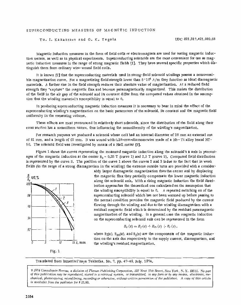
Figure 1 shows the curves representing the measured magnetic induction along the solenoid's z axis in percent- ages of the magnetic induction at the center B 0 = 0,25 T (curve 1) and 2.5 T (curve 2). Computed field distribution is represented by the curve 3. The position of the curve 1 above the curves 2 and 3 isdue to the fact that in weak fields (in the range of a strong diamagnetism in the winding) the extreme outside turns are provided with a consider-
ably larger diamagnetic magnetization than the center and by displacing B Ig0, ~. the magnetic flux they partially compensate the lower magnetic induction Bo along the solenoid axis. With a rising magnetic induction the field distri-
1 / 7 0 ~ butlon approaches the theoretical one calculated on the assumption that ! the winding susceptibility is equal to 0. A repeated switching on of the
superconducting solenoid which has not been warmed up before passing to 98 N ~ the norma I condition provides the magnetic field produced by the current
J flowing through the winding and due to the winding diamagnetism with a q5 ~ residual magnetic field which is determined by the residual paramagnetic
magnetization of the winding. In a general case the magnetic induction 9* ~ \ on the superconducting solenoid axis can be represented in the form
\\ Bz (z) =- B 1 (z) + B m (z) -1- Br (z), 92
where BI(Z), Bm(Z), and Br(Z ) are the components of the magnetic induc- tion on the axis due respectively to the supply current, diamagnetism, and
O 5 lg 15-z,,mm the winding's residual magnetization.
Fig~ 1
Translated from Izmerite! 'naya Tekhnika. No. 7, pp. 47-49, July. 1974.
�9 1974 Consultants Bureau, a division of Plenum Publishing Corporation, 227 West 17th Street, New York, N. Y. 10011~ No part of this publication may be reproduced, stored in a retrieval system, or transmitted, in any form or by any means, electronic, me- chanical, photocopying, microfilming, recording or otherwise, without, written permission of the publisher. A copy of this article is available from the publisher for $15.00.
1054
- [3r ( z ) 7 O,027
0,,926
O,02 S . . . . ~ - - -
O
/ Z too, % If~ I
\
110
7~'Z, m m
700
go p /
go
Pig. 2 Fig. 3
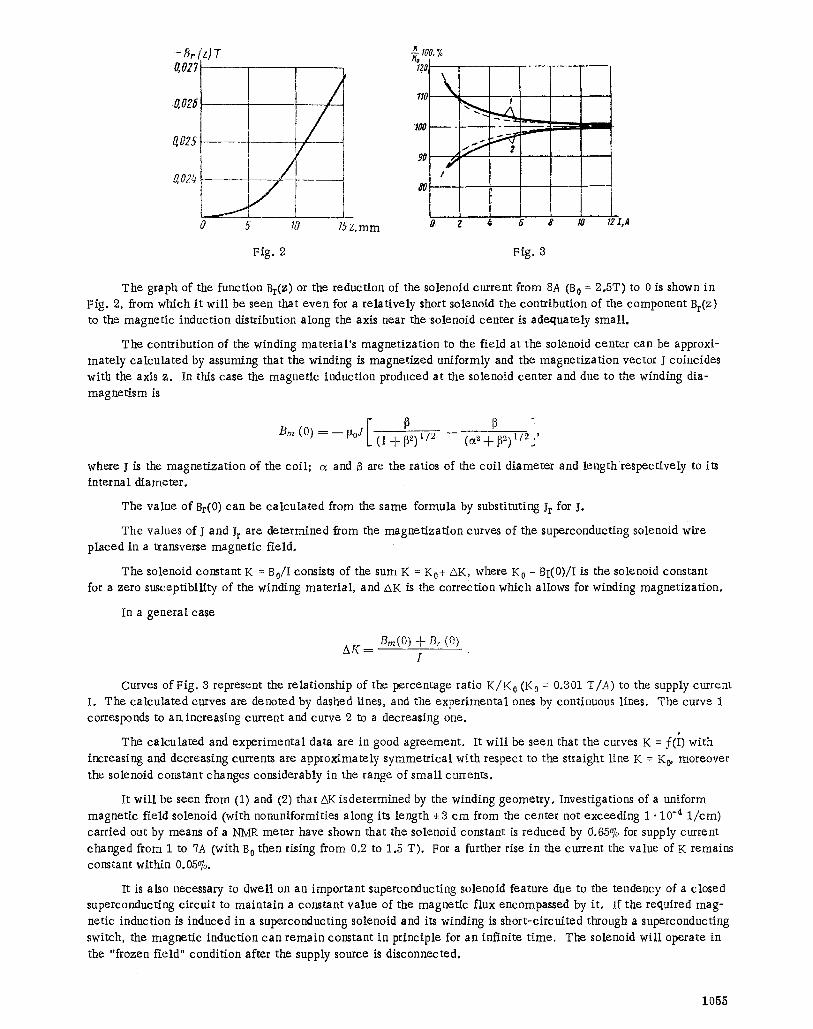
The graph of the function Br(z ) or the reduction of the solenoid current from 8A (B 0 = 2.5T) to 0 is shown in Fig. 2, from which i t wi l l be seen that even for a re la t ive ly short solenoid the contr ibution of the component Br(Z ) to the magnet ic induction distribution along the axis near the solenoid center is adequately smal l .
The contribution of the winding mater ia l ' s magnet iza t ion to the f ield at the solenoid center can be approxi- mate ly ca lcu la t ed by assuming that the winding is magnet ized uniformly and the magnet iza t ion vector J coincides with the axis z. In this case the magnet ic induction produced at the solenoid center and due to the winding dfa-
magnet ism is
B m ( 0 ) = - - r t 0 J - ( l + ~ 2 ) x / 2 - - ( a S 2)1/z '
where I is the magnet iza t ion of the coi l ; a and B are the ratios of the coi l d iameter and length respect ively to its internal d iameter .
The value of Br(0) can be ca l cu la t ed from the same formula by substituting Ir for I.
The values of J and Jr are determined from the magnet iza t ion curves of the superconducting solenoid Wire p laced in a transverse magnet ic f ie ld .
The solenoid constant K = B0/I consists of the sum K = K0+ zSK, where K 0 = BI(0)/I is the solenoid constant for a zero susceptibi l i ty of the winding mater ia l , and zXK is the correct ion which allows for winding magnet iza t ion.
In a general case
AK-= Bin(O) + Br (0) I
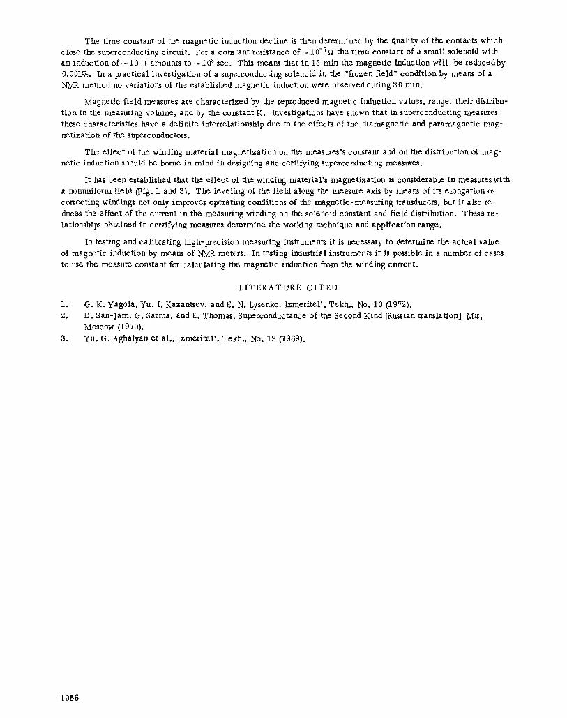
Curves of Fig. 3 represent the relat ionship of the percentage ratio K / K 0 (K 0 = 0.301 T/A) to the supply current
I. The ca lcu la t ed curves are denoted by dashed lines, and the exper imenta l ones by continuous lines. The curve 1 corresponds to an increasing current and curve 2 to a decreasing one.
The ca lcula ted and exper imenta l data are in good agreement . It wi l l be seen that the curves K = f ( i ) with
increasing and decreasing currents are approximate ly symmet r i ca l with respect to the straight l ine K = K 0, moreover
the solenoid constant changes considerably in the range of sma l l currents.
It wi l l be seen from (1) and (2) that z:xK isde termined by the winding geometry . Investigations of a uniform magnet ic field solenoid (with nonuniformities along its length ~-3 c m from the center not exceeding 1 �9 !0 -4 1 / cm) carried out by means of a NMR meter have shown that the solenoid constant is reduced by 0.65% for supply current
changed from 1 to 7A (with B 0 then rising from 0.2 to 1.5 T). For a further rise in the current the value of K remains constant within 0.05%.
It is also necessary to dwell on an important superconducting solenoid feature due to the tendency of a closed superconducting c i rcui t to mainta in a constant value of the magnet ic flux encompassed by it . If the required mag- netic induction is induced in a superconducting solenoid and its winding is shor t -c i rcui ted through a superconducting
switch, the magnet ic induction can r ema in constant in principle for an infinite t ime. The solenoid wi l l operate in
the "frozen field" condi t ion after the supply source is disconnected.
1055
The t ime constant of the magnet ic induction decl ine is then determined by the qual i ty of the contacts which close the superconducting c i rcui t . For a constant resistance of ~ 10"7fl the t ime constant of a smal l solenoid with an induction of ~ 10 H amounts to ~ 108 sec. This means that in 15 min the magnet ic induction wi l l be reducedby 0.001%. In a prac t ica l investigation of a superconducting solenoid in the "frozen field" condi t ion by means of a NMR method no variations of the established magnet ic induction were observed during 30 rain.
Magnet ic f ie ld measures are charac ter ized by the reproduced magnet ic induction values, range, their distribu- t ion in the measuring volume, and by the constant K. Investigations have shown that in superconducting measures these characterist ics have a definite interrelationship due to the effects of the diamagnet ic and paramagnet ic mag- net izat ion of the superconductors.
The effect of the winding mate r ia l magnet iza t ion on the measures's constant and on the distribution of mag- netic induction should be borne in mind in designing and cert ifying superconducting measures.
It has been established that the effect of the winding mater ia l ' s magnet iza t ion is considerable in measures with a nonuniform field (Fig. 1 and 8). The level ing of the f ield along the measure axis by meam of its e longat ion or correcting windings not only improves operating conditions of the magnet ic -measur ing transducers, but i t also re- duces the effect of the current in the measuring winding on the solenoid constant and f ield distribution. These re- lationships obtained in cert i fying measures determine the working technique and appl ica t ion range.
In testing and ca l ibra t ing high-precis ion measuring instruments i t is necessary to determine the ac tua l value of magnet ic induction by means of NMR meters. In testing industrial instruments i t is possible in a number of cases to use the measure constant for ca lcula t ing the magnet ic induction from the winding current.
LITERATURE CITED
I. G.K. yagola, Yu. I. Kazantsev, and E. N. Lysenko, Izmeriter. Tekh., No. I0 (1972). 2. D. San-Jam, G. Sarma, and Eo Thomas, Superconductance of the Second Kind [Russian translation], Mir,
Moscow (19'70). 3. Yu. G. Agbalyan et al . , I z m e r i t e l ' . Tekh., No. 12 (1969).
1056