Embed Size (px)
Citation preview

Superconducting Linacs: Why and How?
P N Prakash IUAC, New Delhi
IUAC
B.Sc. Summer Students Programme 2018
Inter University Accelerator Centre - June 14, 2018

Outline
• Introduction
• Van de Graff and Tandem Accelerator
• Quest for High Energies
• Superconducting Cavities & Linacs
• SC Linac Projects in India
IUAC

Charged Particle Acceleration
The Lorentz Force experienced by a charged particle:
F q E v B
W F.dl q (E v B).dl q E.dl q (v B).dl
Energy gained by the charged particle:
W q E.dl q (v B).vdtdl vdt,but so:
IUAC

Acceleration
In Particle Accelerators:
• Longitudinal electric fields are required for
accelerating charged particles.
• Magnetic fields are used for bending the
charged particle beams and for guidance
& focusing.
IUAC

Energy Gain
Output
Energy
Eout (> Ein)
charged
particle
beam
(p+, e-,
O6+, Ni8+
etc.)
Input
Energy
Ein
+
-
How is the energy of the beam increased ?
Energy Boosting
Device: Particle
Accelerator
EGain=Eout-Ein
IUAC

Accelerator - Example
A simple Particle Accelerator:
Energy gained by the electron:
EGain = q.V = 1x100 = 100 eV (electron volt)
Such DC - or static fields (voltages) - are used in Cockroft-
Walton generators and Van de Graff / Pelletron accelerators.
100 V
e- - +
IUAC

Cockroft Walton Generator IUAC
Cockroft Walton Generator (voltage multiplier).

Van de Graff Generator - Principle IUAC
0 0
1 q q q 1 1V(r) V(R)
4 r R 4 r R
since r < R; V(r) > V(R)
0
1 Q qV(R)
4 R R 0
1 Q qV(r)
4 R r&
Two conducting spheres
one inside the other.
Thus, charge on the outer sphere of radius R can be piled
up and the potential, can be increased to very
large values; at least until breakdown is reached. 0
1 QV(R) ,
4 R
irrespective of the value of “+Q”
When a conducting path is provided, charge will
flow from the inner sphere to the outer sphere !!

Van de Graff Generator IUAC
Left: Van de Graff Generator, and right: Van de Graff Accelerator at
Chalk River Laboratories, Canada.

Tandem Van de Graff IUAC
Ez Ez
The 15UD Pelletron Accelerator
at IUAC is a Tandem Accelerator.
z
15 UD Pelletron at IUAC IUAC
The Pelletron
Accelerator is
housed inside
the tower.

15 UD Pelletron at IUAC IUAC

Pelletron – Energy Gain
PelletronE 1.V q.V (1 q)V
ground to Terminal
(-ve ion) from Terminal to ground
(+ve ion with charge q)
0E E (1 q)V
Example:
Let: E0=200 keV (0.2 MeV), V=13 MV, q=10
E = 0.2 + (1+10)13 MeV
E = 143.2 MeV (1 MeV = 106 eV)
V
qV
E0
Pelletron Accelerator, such as
the one at IUAC, New Delhi.
IUAC
Start with a -ve Ion, strip it of electrons in
the Terminal and convert it into a +ve Ion.
Terminal

Quest for High Energies IUAC
High Energy Physicists
are looking for particle
beams of higher and
higher energies to
explore new physics
as close to t=0 (Big
Bang) as possible.
Nuclear Physicists
also look for high
energy heavy ion
beams above the
Coulomb barrier to
explore new physics.

Accelerators - Classification IUAC
ACCELERATORS
DC
(Van de Graff,
Tandem)
CYCLIC
(Cyclotron,
Synchrotron)
LINAC
(Room Temp.,
Superconducting)

DC Accelerators
Electrical breakdown (flash) is the major limitation in
going to higher Terminal Voltages (and therefore
achieving higher energies).
IUAC
The highest Terminal Voltage achievable is ~20 MV.
Increase in the Terminal Voltage means increase in the
size of the Outer Tank (that contains the insulating
gas).
Also, the Accelerator can only be vertical, since
sagging of the horizontal column is an issue. Going up
vertically, however, has its own limitations !!

Synchrotron IUAC
Synchrotron at
RRCAT, Indore.
Synchrotrons are not suitable for
accelerating electrons, unless the
accelerator is especially designed for
producing Synchrotron Radiation !!
4
1P
mRadiated Power
p
e
m2000
mremember,

Overcoming Limitations
• To increase the beam energy further, time-dependent
electric fields [rather than static (DC) electric fields]
have to be utilized.
• Such time-dependent electric fields are produced in
devices called CAVITY RESONATORS, which
operate at radio frequency (RF); typically around
hundreds of megahertz (MHz) frequency.
• A Linear Accelerator, or LINAC, uses a series of
cavities placed one after the other, to accelerate the
particle beam.
How to increase the beam energy further ?
IUAC

Acceleration in LINACS
In this representation, each
step indicates an RF Cavity
Resonator that boosts the
energy of the beam further.
In this way the energy of the beam can be increased
indefinitely by adding more and more Cavities.
#1
#2
#3
#4
#5
#6
Cavity Resonators
#1 #2 #3 #4 #(n-1) #n
Beam
Axis Ein Eout
EGain=Eout-Ein
IUAC

• A Linear Accelerator (LINAC) in which a series of Resonant Cavities
are installed one after the other to produce ion beams of high
energies, is called an “Independently Phased LINAC”.
• This is because each resonant cavity can be independently powered
and set up, so that when the beam bunch arrives at its entrance it
can accelerate it. This of course means that each cavity has its own
RF Amplifier and Control Module.
• Remember, as the beam gains energy, its speed changes !!!
Independently Phased LINAC
Independently Phased Resonators
#1 #2 #3 #4 #(n-1) #n
Beam
Axis Ein Eout
IUAC

ILC
The proposed International Linear Collider (ILC) will be a
500 GeV e--e+ collider. It will use 16,000 cavities placed in series
one after the other; the total length of which is 31 Km.
IUAC
A LINAC has the advantage, besides
being modular, of not losing beam
power due to radiation.

Cavities - Classification IUAC
Accelerating Cavity
Resonators operating in
TEM Mode. They are
used for accelerating
particles moving at
slower speeds (<0.5c).
They are cylindrical in
shape with one or more
central elements.
Cavities operating in TM
Mode. They are used for
accelerating particles
moving at high speeds
(>0.5c). They are usually
Elliptical in shape, with
several cells in a single
structure.

How do TM Class cavities look?
RF
Power In
Beam Induced
Power Out βλ/2
The ILC requires 16,000 such 9-cell
Superconducting Niobium Cavities !!
βλ/2
Single Cell Cavity
Transverse Magnetic, or TM-Class Elliptical Cavities, are used for particle
acceleration in e--e+ Colliders and high energy sections of H+ LINACS.
IUAC

How do TEM Class cavities look?
Transverse Electric & Magnetic, or TEM-Class Resonators, are
used for accelerating heavy ions which move at slow speeds.
/4 E
H
Quarter Wave Resonator
E ℓ= /2
H
H
Beam
Axis
Half Wave Resonator
IUAC

How does a Resonant Cavity work ??
IUAC

Standing Wave
Standing waves produced on a string.
IUAC
In a Resonant Cavity
such Standing Waves
are produced.
However, the waves in
a Cavity are
Electromagnetic !!!

Pill-Box Cavity – TMnpj Mode
Electric and magnetic fields in the pill-box
cavity in the TM010 mode.
Jn(x) as a function of x.
z n c,np jE J (k r)cos(n )cos(k z)exp(i t)
zH 0
j 'r n c,np j
c,np
kE J (k r)cos(n )sin(k z)exp(i t)
k
j
n c,np j2c,np
k nE J (k r)sin(n )sin(k z)exp(i t)
k r
0r n c,np j
c,np
i nH J (k r)sin(n )cos(k z)exp(i t)
k r
'0n c,np j
c,np
iH J (k r)cos(n )cos(k z)exp(i t)
k
The general solution of the time
dependent fields in TMnpj modes is
given by:
IUAC
Pill Box
Cavity
b
H
E

TEM Class Resonant Cavity
Consider a Co-axial Cylinder having conducting walls:
Beam
Axis
Attach Beam Ports so that the
structure becomes useful for
acceleration.
Such a structure is called a Transverse Electric-Magnetic, or
TEM-Class Coaxial Cavity Resonator.
Introduce a conductive “loading element” and attach it to the cavity
with conducting end caps.
when , or
transverse electric-magnetic standing
wave modes can exist in the cavity.
ℓ
2 2
n
IUAC

Coaxial Resonator
x
y
z
r
θ
Imagine a current wave on the inner conductor traveling
in the +z direction:
0I I exp j( t kz)
This current produces an azimuthal
magnetic field:
0 0B I 2 r exp j( t kz)
The radial electric field Er will be:
r 0 0E I c 2 r exp j( t kz)
Coaxial Resonator
IUAC

Coaxial Resonator
x
y
z
r
θ
Similarly, a current wave traveling in the -z direction is
given by:
0I I exp j( t kz)
This current will produce an
azimuthal magnetic field:
0 0B I 2 r exp j( t kz)
The radial electric field Er is:
r 0 0E I c 2 r exp j( t kz)
Coaxial Resonator
IUAC

Coaxial Resonator
The waves traveling in the +z and –z directions add to produce
a standing wave satisfying the boundary condition Er = 0 at z=0
and z=ℓ.
z=ℓ
Coaxial Resonator
x
y
z
r
θ
z=0 ℓ
0 0IB cos p z exp j( t)r
The non-zero field components are:
0 0r
0
IE 2j sin p z exp j( t)
2 r
z
p ck c ,p 1,2,3........where,
IUAC
Coaxial Resonator
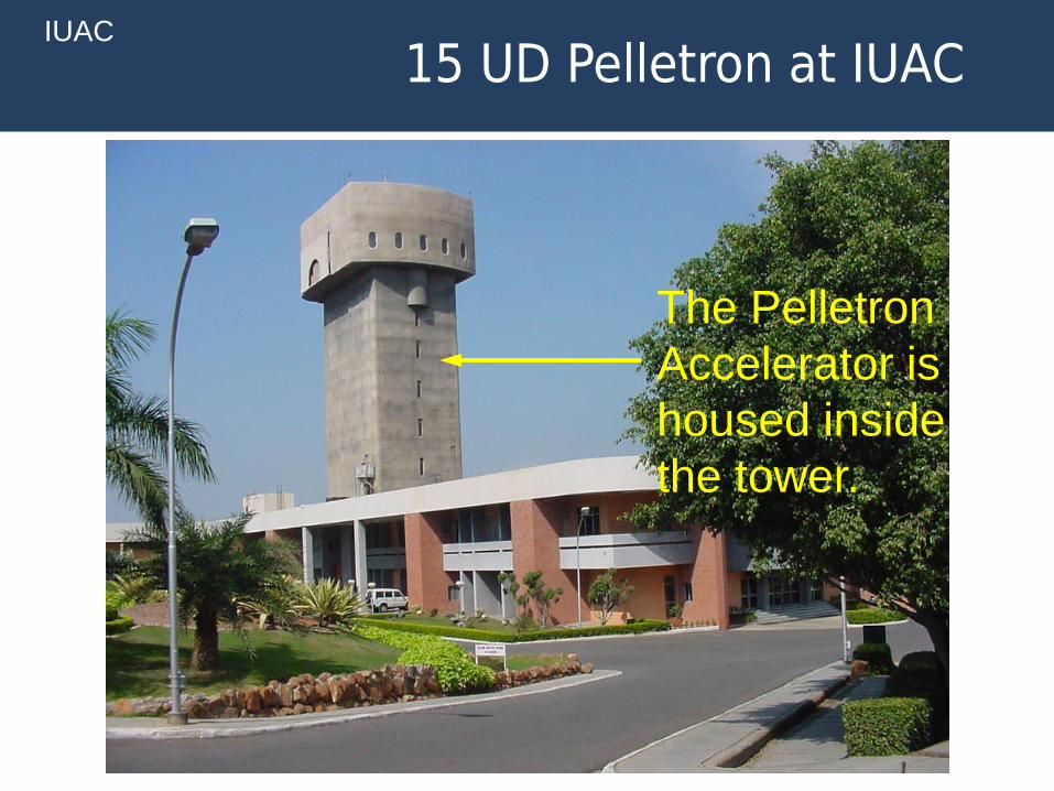
0 0r
0
IE 2j sin p z exp j( t)
2 rRadial electric field:
we know: j exp j 2 .
0 0r
0
IE 2 sin p z exp j( t 2)
2 r
Bθ
A
A
N
Er
N N
A
This shows that the Electric and
Magnetic standing waves have a
phase difference of π/2 between them.
Er
Beam Ports are
attached where
Er is maximum.
The electromagnetic energy
oscillates between the electric
and magnetic fields.
0 0IB cos p z exp j( t)r
azimuthal magnetic field:
&
IUAC

How do ions gain energy ?
E E
d2
Beam
Axis
Coaxial Resonator
E
H
( v c)
H
E
+ve ion
IUAC

Accelerating Module
The inside of a LINAC Cryomodule which has eight Quarter Wave Resonators installed
one after the other. This picture is from the Superconducting LINAC at IUAC.
IUAC

Accelerating Gradient
The longitudinal Electric Field Ez experienced by a
charged particle in the cavity resonator is averaged
over the effective length over which the accelerating
electric field extends.
Ea is the average accelerating gradient (or field, if
you like), in the cavity which extends over the
effective length, Leff .
z a effE dz E L
IUAC

Accelerating Gradient
Gain z a effW E q E dz qE L
Much of the R&D in the field of Linear Accelerators is
therefore devoted towards producing and maximizing
the accelerating gradient Ea, for a given amount of
input power.
Energy gained by a particle having charge q:
IUAC

Enter Superconductivity !!!
IUAC

Superconductivity
• Microwave surface resistance of high conductivity materials:
• Cu at 300 K @ 100 MHz frequency, Rs ~3 mΩ
• Nb at 4.2 K @ 100 MHz frequency, Rs ~10 nΩ
IUAC
Energy stored Energy stored UQ=2 2 f
Energy dissipated per cycle Power dissipated P
The efficiency with which an accelerating structure stores
(or retains) the energy is given by the figure of merit
“Quality Factor”, usually denoted by Q (or Q0).
where ω is the angular frequency, U is the stored energy in
the cavity and P is the power dissipated in the cavity walls.
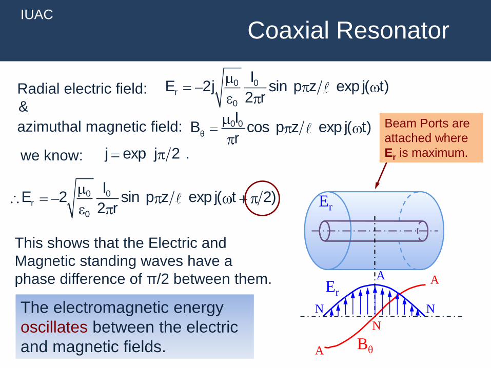
Superconductivity
The most striking features of a superconducting resonator
are the accelerating electric field Ea and the quality factor Q.
• High accelerating fields achieved in superconducting
resonators make the accelerator compact.
• High quality factor reduces the total power required to
produce / generate those fields.
IUAC
s 5Cu
s Nb
R10
R5Nb
Cu
Q10
QQ~109 versus 104

Superconductivity
Normal
Conducting Superconducting
Frequency (MHz) 100 100
Stored Energy (J/(MV/m)2) 0.1 0.1
Quality Factor (typical) 1 104 2 108
Accelerating Field (MV/m) 3 3
Power dissipated (W) 56,000 3
The superconducting resonator reduces the required wall plug power by
a factor of >100, which is very-very significant !!
Comparison between a resonator made from normal conducting material
(e.g. copper) and superconducting material (e.g. niobium):
Carnot
4.20.014
300 4.2
Refrigerator Efficiency ~0.2
Net Efficiency ~0.003
Wall Plug Power ~1 KW
Superconducting:
RF Source Efficiency ~0.5
Wall Plug Power ~112 KW
Normal Conducting:
AC Power required 112 KW 1 KW
higher than actual !! lower than actual !!
IUAC

Clearly, superconducting accelerating structures
have advantage over room temperature structures
in terms of the wall plug power required.
However, they have their set of issues.
Life is never easy !!
IUAC

Issues with SC Cavities
Superconducting Niobium Cavities are non-trivial to develop:
• They need to be designed to maximize the gradient
without reaching the fundamental limit of the critical
magnetic field (most important among the limits).
• They need to be designed to operate at low temperatures
(4K, or 2K in some cases).
• They require special infrastructure to construct.
• Niobium is an expensive material US$750-1000/Kg);
each cavity typically requires 10s of kilograms of material.
• Constructing a Superconducting Cavity is a finicky and
risky process.
• Diagnosing problems in Superconducting Cavities can
become very tricky.
IUAC

Developments at IUAC
Superconducting Niobium Cavity development at IUAC:
• IUAC is the first laboratory in India to set up the necessary
infrastructure to indigenously build Superconducting
Niobium Resonant Cavities.
• Two thirds of the SC Resonators used in the IUAC Linac
are built indigenously using this infrastructure.
• IUAC has also collaborated with several Indian
Laboratories to develop niobium cavities of different
designs.
• IUAC has collaborated with Fermi National Accelerator
Laboratory to develop Single Spoke Resonators for a
project (details in later slide).
IUAC

Superconducting Booster LINAC
Quarter Wave Resonator
(QWR) used in IUAC Linac.
15 UD Tandem Pelletron Accelerator &
Superconducting Linear Accelerator (SC LINAC)
IUAC

Indigenously Developed QWRs
IUAC QWR
IUAC

SC LINAC at IUAC IUAC

Fermilab PIP-II & Indian Programs
HWR SSR1 SSR2 Elliptical Cavities
IUAC
• Proposed High Intensity Superconducting Proton
Accelerators in India (ISNS, ADS)
- Accelerators similar to PIP-II
- Overlapping Technologies
Accelerator Development - BARC, RRCAT, IUAC & VECC
Indian Institutions and Fermilab Collaboration (IIFC)
Proton Improvement Plan (PIP-II) at Fermilab, USA.

Spoke Resonator - SSR1
The two SSR1 Niobium Spoke Resonators developed at IUAC.
IUAC

IUAC SSR1 S104 Test Result
2 K Test Result of SSR1 S104 developed at IUAC and tested at Fermilab. The
PIP-II and PXIE Design Goals are Eacc=10 & 12 MV/m respectively at Q>5 109.
IUAC SSR1 S104
IUAC

There are several other developments but it is
beyond the scope (and time) for this lecture…..
IUAC

Thank you
IUAC


![Proton and Carbon Linacs for Hadron Therapytest - which completely correspond to beam dynamics calculations - are summarized in Refs . [8, 9]. A linac is made of about ten µUnits](https://img.pdfslide.us/doc/110x75/60c825da71b17752b668cbfa/proton-and-carbon-linacs-for-hadron-therapy-test-which-completely-correspond-to.jpg)


![Superconducting TESLA cavities - CERN · set for the TESLA Test Facility (TTF) linac [2]. The TESLA cavities are quite similar in their layout to the 5-cell 1.5 GHz cavities of the](https://img.pdfslide.us/doc/110x75/5f08b08b7e708231d4233ee5/superconducting-tesla-cavities-cern-set-for-the-tesla-test-facility-ttf-linac.jpg)