Embed Size (px)
Citation preview
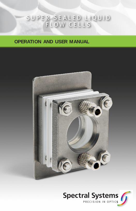
S U P E R - S E A L E D L I Q U I D F L O W C E L L S
OPERATION AND USER MANUAL

Introduction
The Spectral Systems Super‐Sealed™ Liquid
Flow Cells are designed and manufactured
for continuous flow infrared transmission
sampling applications. The large port
diameter permits higher flow rates to speed
feedback of component concentration.
Spectral Systems Super‐Sealed Liquid Flow
Cells are designed for optimized laminar
flow allowing the sample to flow with
minimized lateral mixing. The proprietary
seal technology used in our Super‐Sealed
Liquid Flow Cells provides for leak free
operation, exceptional durability and
maximum sample compatibility. The cell
mount for the Super‐Sealed Liquid Flow Cell
is the standard 2.0” × 3.0” side mount to fit
your FT‐IR spectrometer. All Super‐Sealed
Liquid Flow Cells are manufactured with
Luer Lock fill ports for covenient coonection
with flow tubing and peristaltic pumping
systems. The Super-Sealed Liquid Flow Cells
are available with your selection of sampling
pathlength and window materials. Window
materials used in the Super-Sealed Liquid
Flow Cells are of the highest quality
composition and maximum flatness for
precision quantitative analysis. To increase
IR throughput and minimize spectral fringing
of high refractive index window materials
we utilize our Spectral Systems XP‐BBAR™
coating on our Super‐Sealed Liquid Flow
Cells. Please contact us for additional
performance features.
For your convenience we offer factory
calibration of any of our Super-Sealed
Liquid Flow Cells.
Optimized Design for Continuous Flow Applications• Rugged, heavy duty design compatible with continuous use
• Large IR port diameter to accommodate high flow rates
• Proprietary seal technology for leak free operation
• Designed for optimized flow
• Rectangular plate design to fit your FT‐IR spectrometer standard slide mount
• Proprietary coating applied to high refractive index windows to maximize IR throughput and minimize undesirable fringing
• Individually serialized to aid in record keeping
• Optional factory calibration for your convenience and method certainty
2
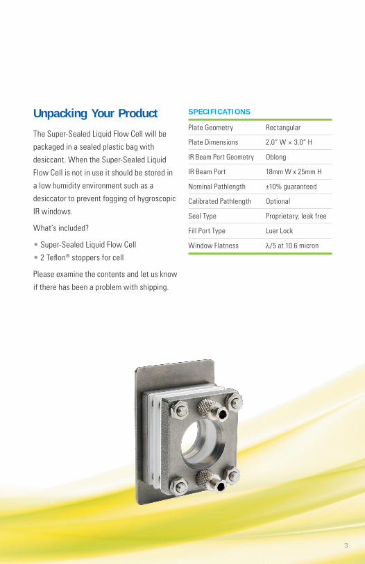
Unpacking Your Product
The Super-Sealed Liquid Flow Cell will be
packaged in a sealed plastic bag with
desiccant. When the Super-Sealed Liquid
Flow Cell is not in use it should be stored in
a low humidity environment such as a
desiccator to prevent fogging of hygroscopic
IR windows.
What’s included?
• Super-Sealed Liquid Flow Cell
• 2 Teflon® stoppers for cell
Please examine the contents and let us know
if there has been a problem with shipping.
SPECIF ICATIONS
Plate Geometry Rectangular
Plate Dimensions 2.0” W × 3.0” H
IR Beam Port Geometry Oblong
IR Beam Port 18mm W x 25mm H
Nominal Pathlength ±10% guaranteed
Calibrated Pathlength Optional
Seal Type Proprietary, leak free
Fill Port Type Luer Lock
Window Flatness λ/5 at 10.6 micron
3

Determining Cell Pathlength
Your Super-Sealed Liquid Flow Cell has been
factory tested for pathlength prior to
shipping to ensure that it is within ±10% of
its nominal pathlength. You can determine
its precise pathlength by using the following
procedure.
1. Collect an open beam background
spectrum on your FT-IR.
2. Collect the spectrum of the empty cell.
The resulting spectrum will exhibit a
fringing pattern resulting from the
reflection of the IR beam between the
opposing surfaces of the open cell.
3. Select a region of the spectrum where
the fringing pattern is distinct – free of
interference (water bands, etc.) and note
beginning and ending point values in cm-1
for a significant number of fringes. Figure 1
shows the spectrum of a 0.1 mm
Super-Sealed Cell.
Notes: High spectral resolution is required for calculating the pathlength of the longer pathlength cells in order to provide sufficient data points for the measurement. Table 1 shows minimum spectral resolution settings required. For all shorter pathlength cells a spectral resolution setting of 4 cm-1 is adequate.
4. The pathlength of the cell can be
calculated from the following equation1:
Pathlength = 10 N/2(λ1 – λ2)
Where;
Pathlength = value in mm
N = number of fringes between λ1 and λ2
λ1 = starting value in cm-1 for measurement
λ2 = ending value in cm-1 for measurement
In the example shown in Figure 1, λ1 =
2534.38 cm-1, λ2 = 1138.93 cm-1 and N = 29.
From this we calculate the actual pathlength
to be 0.104 mm.
Spectral Systems offers an optional cell
calibration for their Super-Sealed Liquid
Flow cells. This factory calibration provides
you with verification of cell pathlength
especially useful in regulated laboratory
environments. With selection of the
Calibration of Liquid Flow Cell option, you
will receive a label on the cell and a
certificate stating the factory calibrated cell
pathlength. It is important to remember that
cell pathlength could change with use, i.e.
solubility or abrasion of window material
with use.
Figure 1. Spectrum of 0.1 mm pathlength Super-Sealed Cell
4
Minimum Spectral Resolution Required
CELL MINIMUM PATHLENGTH SPECTR AL (mm) RESOLUTION (cm -1)
10 0.25
5 0.5
1 2.5
0.5 5.0
Table 1
Sampling Procedures
Samples measured in sealed liquid flow cells
are generally a component in a base liquid,
for example an additive in fuel for a
combustion engine. Generally the pathlength
of the liquid cell is chosen to optimize the
absorbance of the component which needs
to be measured. Often the components of
interest are at low concentrations within the
base liquid; parts per million (ppm) and low
percentage levels are typical. Therefore, we
generally need to choose longer pathlength
cells to “see” and measure these low
concentration levels.
The primary absorbance bands from the base
liquid generally are out of the linear range of
the spectrometer and therefore cannot be
used to internally calibrate the pathlength of
the measurement. In these cases the use of
a fixed and reproducible pathlength cell is
essential. In some sample measurements
weakly absorbing bands of the base liquid
can be used as a measure of the liquid cell
pathlength. In these cases the absorbance of
the component of interest can be ratioed to
an absorbance band of the base liquid to
determine concentration and a fixed
pathlength cell aids in the precision of the
quantitative measurements.
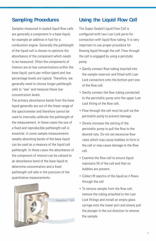
Using the Liquid Flow Cell
The Super-Sealed Liquid Flow Cell is
configured with two Luer Lock ports for
connection with liquid flow tubing. It is very
important to use proper procedure for
flowing liquid through the cell. Flow through
the cell is engaged by using a peristalic
pump.
• Gently connect flow tubing inserted into
the sample reservoir and fitted with Luer
Lock connectors onto the bottom port one
of the flow cell.
• Gently connect the flow tubing connected
to the peristaltic pump onto the upper Luer
Lock fitting of the flow cell..
• Flow through the cell must be pull via the
peristaltic pump to prevent damage.
• Slowly increase the setting of the
peristaltic pump to pull the flow to the
desired rate. Do not set excessive flow
rates which may cause bubbles to form in
the cell or may cause damage to the flow
cell.
• Examine the flow cell to ensure liquid
maintains fill of the cell and that no
bubbles are present.
• Collect IR spectra of the liquid as it flows
through the cell
• To remove sample from the flow cell,
remove the tubing attached to the Luer
Lock fittings and install an empty glass
syringe onto the lower port and slowly pull
the plunger in the out direction to remove
the sample.
5

6
Cleaning and Storing the Liquid Cell
Before storing the liquid flow cell after use it
is important to remove all sample residue to
prevent long-term damage to the cell.
Pull a suitable solvent through the cell using
the following method:
• Install a Luer Lock glass syringe with
solvent onto the lower port of the flow
cell. Install an empty glass syringe onto
the upper port of the flow cell. Gently pull
the plunger of the upper syringe out to
draw the solvent into the flow cell. It is
recommended this be done three times
using three times the volume (each time)
of the liquid cell to completely remove
sample residue.
• Store the Super-Sealed Liquid Flow Cell in
a desiccator to prevent damage to
hygroscopic IR transparent windows.
Product Configurations
The Super‐Sealed Liquid Flow Cell is
available with your selection of sampling
pathlength and window materials. Table 2
shows a complete list of Spectral Systems
part numbers for these configurations. Each
of the window materials have of course
unique properties and capabilities relative to
spectral range and water solubility. We coat
the outer surface of the ZnSe Super‐Sealed
Liquid Flow cell with our XP-BBAR to
increase IR throughput and reduce fringing
effects. For your convenience we have listed
these properties for each of the materials in
Table 3.
Safety PrecautionsIt is essential to utilize safe laboratory
procedures when using the Super-Sealed
Liquid Flow Cells. Safety protective
eyeglasses and laboratory gloves are
required.
Follow proper cell filling and emptying
procedures as outlined in Sampling
Procedures. Failure to do this may cause
liquid cell damage and or exposure to the
liquid sample.
Make sure your sample is compatible with
the window material of the sealed cell.
Failure to do this may cause liquid cell
damage and or exposure to the liquid sample.
If any damage to the cell is detected, please
contact Spectral Systems for assistance. If
the cell leaks it cannot be repaired in the field.
References:
1. Conley, Robert T., Infrared Spectroscopy
(Allyn & Bacon, 1966).

Part Numbers List for Super-Sealed Liquid Flow Cells
PATHLENGTH (MM) 1.0 0 2 .0 0 4 .0 0 VOLUME (ML) 0 .47 0 .94 1.8 8
CaF2 097-76-001 097-76-002 097-76-003
ZnSe, XP BBar 097-72-001 097-72-002 097-72-003
Table 2. Super‐Sealed Liquid Flow Cells include Teflon stoppers for storing the cell when not in use. Special versions of these cells are also available from Spectral Systems. Versions with specialized coatings to increase IR throughput and versions with window wedging to improve performance for high‐resolution measurements are available. Please contact us for more nformation for your requirements..
Spectral Range and Water Solubility for Super-Sealed Liquid Flow Cells
WINDOW MATERIAL CaF 2 ZnSe
Short Wavelength, cm-1 79,500 5,000
Long Wavelength, cm-1 1025 508
Solubility, g/100g 0.0017 0
Table 3. Where SWL = highest wavenumber, LWL = lowest wavenumber and solubility is the value at room temperature
7
Replacement Parts
DESCRIP TION PART NO.
Teflon Stoppers (12 each) 097-3711
Glass Syringe, 1 mL 097-3801
Glass Syringe, 5 mL 097-3805
Glass Syringe, 10 mL 097-3810
Super-Sealed Liquid Cells Calibration
DESCRIP TION PART NO.
Calibration of Liquid Cell 097-00-000
3 5 C O R P O R AT E PA R K D R I V E • H O P E W EL L J U N C T I O N , N Y 125 3 3
P H O N E: 8 4 5 . 8 9 6 . 2 2 0 0 • FA X : 8 4 5 . 8 9 6 . 2 2 0 3 • I N F O @ S P EC T R A L- S Y S T EM S .C O M
WWW.SPECTRAL-SYSTEMS.COM
9-1
5
©2014 Spectral Systems. Super-Sealed is a trademark Spectral Systems. Teflon is a registered trademark of E.I. du Pont de Nemours & Co.