Embed Size (px)
Citation preview
Ci?eechcmftSuper King Air B2001B200C
SECTION VIISYSTEMS DESCRIPTIONTABLE OF CONTENTS
SUBJECT PAGE
Airframe .......................................................•..................................................................................................•......••.........Structure •.•....•....•......•............................•.......................................•......•..•.....................•.•...•..•.••..............•..•.••...•.........Seating Arrangements ..•...•••.......•.......•••.•..............•...•.•..•........•....•....•.•...•.•••....••..•..•..•.•.•••.•..•.•.••.....•.....•.••.•••.•••.•.......
Flight Controls ..................................................................................................................................................•..............Control Surfaces ........••.••..•..•......•.....••.•.•.•.••..........•..................................•.•.••....•..•.........••...•....••........•..•••.•..•.••••.........Operating Mechanisms ....•..•....•.•.......•..•.•.•....••..•.....•......•........................•.•.•.......•....•...••••..•...•.••.................................Manual Elevator Trim •..•...•.••.•.....•...••....•...•••••.•••..•..••.••..•.....•....••••.•.•..••..••••.•••.•....••.•.•.•.••••..••.•....••.•••.•••..•.•.•••.••••.•.••...Electric Elevator Trim ••.•..........•..•...•..•••.....•.•.•.•........••.•...•...•.....•.•.•......•..••.•.•........•......••.•••••••..••••••......•••.••....•.•••.....•...Rudder Boost ...•.•.•.•••••~....•........••..•••.•.•..•..••••.•.•....•..•.••......•......••••...........•.••••.....•.••.•••.•.•••..•••.•.••.••••.•..•.••••••.•..••..........
Instrument Panel ..~•...•••.......•.•.•...................................................••........•....•....•...............••.••...•.••.•.................•.•..•...........
Annunciator System ............................•....•.....•...........•.••......................•....•..•.•...•.......•...••.•............................................
Ground Control .......•............................................................................•..........•...................•.........•...............•.................
Flaps .................•..•.......................................................................................•..•........•........•......••.......................................
Landing Gear ...•...•........•.•....•........................•.................•...................................................•...••.•........•..........•.•....••.........Mechanical Landing Gear .•••........•.•.......••..•..••..•.....••........•..•.........••...•...•.••.••.....•.••.•...••.....•••.•••••.•.••.•.....•.•..•....••.....•..
Landing Gear Warning System(MechanicalSystem) ..•....••.•.••.........•.•...•.•..•.•......••••.........•..•.....•..•.....••.•..•.••....•..•.•....••••••••••.•.•..••.•.....•.••••••••••...•.•..Manual Landing Gear Extension(Mechanical System) •.•.••.•.•..•••...•..•...•.....•..•.••...............•.......•••••.••.....•.••.•...••••..•.••..••.•••••.....•.••••.••......••.•.•••••••....•...
Hydraulic Landing Gear .•.•..•...••.••••.••.•.•••.....••••••......•.•••..•...........•••...•.....•.••..•..••••.••.•••••••••..•.•••..•••.••....•...••.•.•••••••.•..••..Landing Gear Extension andRetraction (Hydraulic System) ..••...•...•...•..............•.•.................•...•.....•..•.•.....•..••.•...••.••.........•.••.••.•••.•.....•••....•...•.•..Landing Gear Waming System(Hydraulic System) •••.•••••.•....•..•.•••.•••.•......•..•......•...•...•............•.•..•.•••••.•••••••..••.••••...••••••.••....•••••••••••••.•••••••...•.•.•...•..Manual Landing Gear Extension(HydraulicSystem) .••.•.•..•...•...•......•.•.•....•••..............................•.•..•..•..•.••••..•.....••.....••.••...•••..••.•...•.•.•.....•..•.•..••.•..•...
Brake System .•...•.•.••••.••••....••......•••.•..••.•......•...•.............••...•.........•.•..•....•.....•.....•...•.....••..••.•••.••••.•...•••.•...•....••......•..••..Tires ••••....••••...•..•••...•.•...•...............•.........•....•..••..........................•......•.......••.•.....•.........••.••.•..•..•••.•....•..•..•••.•••.•..••.•..••..
Baggage Compartment •.••...............•....................................................•.....•....•...............•..•....••....•...............•.................
Seats, Seatbelts, And Shoulder Harnesses ......................................•.........••.................••..........•....................•............Seats .•.•.••..•.••...•.•......•......•......•....•.....•.••....••................•..............•.....•.....•••.••.....•..•...•.....••••..•.•.••...••••......•.•.•..•...•.•......
Cockpit .••.•....•.•...•..•.........•........••.•..•.•......•.•............•..............................•..•..•.............••••••••.....•.....•.........•.•.••.•.•••......Cabin .•.•.........•.....•.•.•...••.•......................•..•......•...•.•.•............•.•.............•.•••....•..••••....•••...••...•••.•...•.•..•.•••...•••..••........
~~in·~a··:::::::::::::::::::::: :::::::::::::::::::::::::::::::::::::::::::::::::::::::::::::::::::::::::::::::::::::::::::::::::::::::::::::::::::::::::::::::::::Seatbelts •.•....•.•..•.......••................••....••.••....•••.•..........•..........•................•...••••.................••...•.....•............•.................•..Shoulder Hamesses ...••...................................•..........•......................•.......•..••.........................••.•.....•.......••.•...•.•.......•..
Cockpit ..•......•......•.•......••........................•...............•.................................•....•...•........•••...•...•.•.............••.•..••.........••.Cabin .•...•.................................•.....•.......•..•.•............................................•....•....•.....••••••.•.....•.......................•..........Aft-Cabin Area ....•.•..................•.....•..........•......•..................•.................•..•..................•.•.....••.•.............•...................
Doors, Windows, And Exits .Airstair Entrance Door (8200) ..........••...............................................•..............................•...•.•••.................•......•..........Airstair Entrance Door (8200C) ........•......................•................................•..•................•..•.•.....•.............•..........•.......•..
~~~~:~o~:~..::::::::::::::::::::::::::::::::::::::::::::::::::::::::::::::::::::::::::::::::::::::::::::::::::::::::::::::::::::::::::::::::::::::::::::::::::::8200: ..•..........••...•....................•...•.........................•.................................•..........................••...•...............................8200C: .........•..........•.....................••........•..............•......................................•.................••...•...•..................•............
Interior Doors .....................•...........................••...........•......................•..............................•...........................................Cabin Windows •............................................•.....................................................................•...•....•...............................
PolarizedType ........................................................................................................................•................................Shade Type ...................................•..............................................•...........................•.....•........................................
Sunvisors ..........................•...................................................................................................•.......................................Operating Instructions .
Control Locks .
April, 1996
7-57-57-5
7-57-57-57-57-57-5
7-6
7-6
7-12
7-12
7-127-12
7-13
7-137-13
7-13
7-14
7-147-157-15
7-15
7-157-157-157-157-167-167-167-167-167-167-17
7-187-187-197-217-217-227-227-227-227-227-22.7-227-22
7-22
7-1
~Super King Air B20OJB200C
SECTION VIISYSTEMS DESCRIPTION
TABLE OF CONTENTS (Continued)SUBJECT
Engines ............................................................................................•.........•.............................•.......................................Propulsion System Controls ....•...............•..................•.......•........••.••......•....•.......•.........................••..•.............•............
Power Levers .......•.•......................................•......•.....•.•..•....•..••.•.................••.•..............•.......•..•..................•...•.••....Propeller Levers ••..•••..........................•••............•.....•••....•..•.....•....••....•.....•...................•............•.••....••..••........•.•.•...Condition Levers ......•.........•.............••.••...•........••.•.•...•.•.•....•.•.••.........•••.•..••.............................•••.•.•........•...•............Propeller Reversing .......•..............................••......•....•..........•.••••.........•.••.•.......•..................•...••..•.•.........•..•....••......Friction Locks ........•.•...........•........•....••.....•..•.....................•.•..••.•.•......••.......•.••.•.......••.•..•.........•..•......•....•.....•.•..••...
Engine Instrumentation •.....•.................•..•................•..••.•.•...•..••..••.••..•.•.......••..•..•.........................•.........................•....Propeller Synchrophaser (Optional) .....•.•..........••.....•.••••....•.•.•..•••.•.•••..........•••.•.•.•........••..•.......•.•....••.•....•.•...•...•....•....
Type I System .........•.......•....••..............•......••••....••.•..•.•......•...•..•...•..••••.•.•....•.•.•..••.......•.......•.•.•..•..•....•..•......•....•..•.Type II System •.....•.••........•......•...•.......•...........•..•...•......••.••......•..•....••..•.•..................•.•.•.....•...•..•.........•....•........•...
Engine LubricationSystem ........•.........•.•..•......••.•••..••..•••.•.•••.•••.••.•.•.•....••..•.•.•.•.••..........•............••••.•••........••••...•...••.•..Magnetic Chip Detector •......••••....•.......•.•........••••.•••...•••....•.•.•••.•.....•..•............•.....•...............•......•...........•.....•.•..••••.
Starting And Ignition System ..........••.......•............••..•••.•••••..•.........••.••....•.•.•.•...•........•...............•..•.......•..•..•••••........•••..Auto Ignition ........•.•.••.......••.••.......................•.•.•..•••..•........••••...•••...••..•....•.....•......................•..••..•.••.......•........•.•••...
Induction Air System •••.•..........•••.•......•.•..•..•.....•.••...••••••••••..••..•..•....•...•..•••.•.•••.••.•.............•••.....•.•.•..•••.....••.•..••..•.••..••..Ice Protection ....•.••...•..•.......••........•.••......•....••.•.••..•..•.•••.•...••••••••••.••..••.....•.................•••.•••.•.••••.•.•••••••..••.••.••••..••.••••.
Engine Air Inlet •.•......•...••.....•.....•••.•.••.•....••.•.•.•....•......•..•..•..•...•..•.•.•.•..•••..•..........••..•.....•.•......••.....•...•..•......•.•.••.Ice Vanes (Inertial Separator System) ..........••.•.....•...•....•..•....••........••••..•..••...•...........••••....••.•..•.•...•......••.•••.••••.•.•..
Fuel Control .•...•....•..••..••••...................••..••.•.........••.••••••.••...•••.••••.•.••••..••..•..•.••.••.......•....••.••••....••.••••.•••••..••••••....••••..•••..Fire Detection System •••.••.................•....•.........•..•••.••••••.•....••..•.••.•••.•..•.•....••.....••........•..•.•••••..•.•••.•.•••..•....•.•••..••...•.•.••.Fire Extinguisher System .......................••........•..•....•••••.•.•...•..•••••••••.•.••..•....•...•.•.............••••....•••..•...•.••..••••.•••••••.••••.•..
Propeller System ....•.......................................................•...•...•....••..••.•..........•...•..........................................•.••...•......•....Description .......•..•....•..•.•................•.....•..•••......•••.•.•..••••.•.....•••••.•••••••.•.••.•.......•.•..................••...••.•.•.••••.•....••••••••••.•..••••.Primary Low Pitch Stop •..•.....•.................•.....•..•.••...••••••..•••••.•••••..••••....•.......•.•.•............•........•...•...•.•.....•.•••..••.•......•....Propeller Governors .....•.••......•.•.................•...........•..•.........•...•••••••.••..•..........•.....•......•..........•.••.•...•••.....•.•••...•.....•••....Autofeather System .•..•...•........................•...........•.••......•••.........•..•••..............................•...•.•.....•..••••••............•........•.•..
Fuel System .................•............................................•..•................•....•...............•..............•..•........•...•.••...........•..•..•......•..Fuel Pumps .••.••..•••.....•........•.••.•••...•.....•...................••••..•...•..•.•.•...•.................•..•........•.•..............•..•••.•..•...••••.•..•.•.••.•..
Serials 88-734,88-793, 88-829,88-854 thru 88-870, 88-874 tnru 88-891, 88-894, 88-896 thru BB-911,88-913 thru B8-1095, and 88-1097; BL-37 thru BL-57: ......•.......................................•...................•........•............Serials 88-1096, B8-1098 and After; BL-58 and After: ........•......................................................••..............•...•......
Auxiliary Fuel Transfer System .....•....•••...•......•..•..•.•••...........•.•.•.•.••....•..•..••••.••........................•...........•..........••.....••....Use Of Aviation Gasoline .......•.......••....•.............••.•.....••••...••..•..•...•....••......•.......•..........................•..••........•........•.•.•••..Crossfeed .•..•..••..•.....•...........•....•...•....•...•...........••...•••.•..•..••....•.•••..••...•..••.•.•..•.•..•...........................••.•.........•..•••..••.••...Firewall Shutoff .Fuel Routing In Engine Compartment ..............••...•..•.••.•....•...•..••••••...•..........•.......•........•.••.....•.....•..•.•....•......•.•.•....••..Fuel Drains •.••...•......••••...••....••............•.•........•....•••••..•••..•..•••..••.••....•.......••.•...•...•......•...........•.•..........•.....•.•.....••..........Fuel Purge System ...........•........................................................•.............................................................•....................Fuel Gaging System .••..•......•..•.•••...........••...•...•..•.•......•....••.••••..•.•.••••..•.......•.••.................•.....•.•........•.•........•.•.......•••...
Electrical System ..............................................................................................................................................•.............External Power ........••............................................•......•.....•....••...•.•..••..•••..•..•.................••..•............•.........•.•.•....•........
Lighting Systems ...........................................................•................................................................................................Cockpit .........•........•...•..............................•...........•...........•...•...•.......................................•........•....••...............•.•..•........Cabin .............................•....................................•.......•...•......•...••..............................................................•...•..............Exterior ................••....•.............................•.•........•.•.......•...........••.•.•...........................................................•..................
Environmental System .Pressurization System ...................................................•..•.......••...................•..........................................................•..•Flow Control Unit (Thru 88-1179, BL-69) .•...................•....•..................•......••.....................................•.........•..........•...Flow Control Unit (88-1180 and After, BL-70 and After, and Earlier Airplanes In Compliance With Beech ServiceBulletin 2002)............................•..........................•.....••.•..................................•...................................•.......................Unpressurized Ventilation ................................•.....................•........................................;..............•..........................•...Heating ..........................................................................................•.......•.•.•..............................................................•...Radiant Heating .....•.................................•......................•..............•........................................•........................•..•.....•...Air Conditioning System .Environmental Controls ...........................•.............................•......................................................•.....................•.........
Heating Mode .Cooling Mode ......................................................•...................................................................................................Automatic Mode Control .......•..................................................................................................................................Manual Mode Control .
PAGE
7-237-247-247-247-247-247-257-257-257-257-257-267-267-277-277-277-277-277-277-287-297-30
7-307-307-317-317-31
7-317-31
7-327-327-327-327-347-347-347-347-347-34
7-347-35
7-377-377-377-37
7-377-377-40
7-417-427-427-447-447-467-467-467-467-46
7-2 December, 1994
~ftSuper King Air B2001B200C
SECTION VIISYSTEMS DESCRIPTION
TABLE OF CONTENTS (Continued)SUBJECT
Bleed Air Control .Vent Blower Control .
Oxygen System .
Pitot And Static System .
Engine Bleed Air Pneumatic System .Bleed Air Warning System .
Automatic Devices In The Control System .Yaw Damp .
Stall Warning System .
Ice Protection Systems .Windshield Heat .Propeller Electric Deice System .
Prior To B8-829, And Prior To BL-37: .88-829 And After, BL-37 And After: .
Pitot Mast Heat .Surface Deice System .Stall Warning Vane Heat .Fuel Heat .
Comfort Features .Toilet .Relief Tubes .
Cabin Features .Fire Extinguishers .
Windshield Wipers .
Cargo Restraint (B200C) .
December, 1994
PAGE
7-477-47
7-47
7-51
7-537-53
7-537-53
7-53
7-537-537-537-537-547-557-557-577-57
7-577-577-57
7-577-57
7-57
7-58
7-3

Section VIISystems Description
7-4
THIS PAGE INTENTIONALLY LEFT BLANK
OeechcmftSuper King Air B2001B200C
December, 1994
Ci?eechcraftSuper King Air B200/B200C
AIRFRAME
STRUCTURE
The BEECHCRAFT Super King Air B200/B200C is an allmetal, low-wing monoplane. It has fully cantilevered wings,and a T-tail empennage.
SEATING ARRANGEMENTS
The pilot and copilot seats are mounted in a separate forward compartment. Various configurations of passengerchairs and two- or four-place couch installations may beinstalled on the continuous tracks mounted on the cabinfloor. One or two tole-up seats may be installed in the aftcabin area. The toilet is also equipped for use as a seat.Seating for up to 15 persons, including crew, is available.For additional information, refer to the "Cabin ArrangementDiagram" in Section VI, WEIGHT AND BALANCE/EQUIPMENT UST.
FLIGHT CONTROLS
CONTROL SURFACES
The airplane is equipped with conventional ailerons and rudder. It utilizes a T-tail horizontal stabilizer and elevator,mounted at the extreme top of the vertical stabilizer.
OPERATING MECHANISMS
The airplane is equipped with conventional dual controls forthe pilot and copilot. The ailerons and elevators are operated by conventional control wheels interconnected by aT-bar. The rudder pedals are interconnected by linkagebelow the floor. These systems are connected to the controlsurfaces through push-rod and cable-and-bellcrank systems. Rudder, elevator, and aileron trim are adjustable withcontrols mounted on the center pedestal. A position indicator for each of the trim tabs is integrated with its respectivecontrol.
MANUAL ELEVATOR TRIM
Manual control of the elevator trim is accomplished with ahandwheel located on the left side of the pedestal. It is aconventional trim wheel· which is rolled forward for nosedown trim, and aft for nose-up trim.
ELECTRIC ELEVATOR TRIM
The electric elevator-trim system, if installed, is controlled byan ELEV TRIM - ON - OFF switch located on the pedestal,a dual-element thumb switch on each control wheel, a trimdisconnect switch on each control wheel, and a PITCHTRIM circuit breaker in the FLIGHT group on the right sidepanel. The ELEV TRIM switch must be ON for the system tooperate. Both elements of either dual-element thumb switchmust be simultaneously moved forward to achieve nosedown trim, aft for nose-up trim; when released, they returnto the center (OFF) position. Any activation of the trim system by the copilot's thumb switch can be overridden by thepilot's thumb switch. A before take-off check of both dual
December, 1994
Section VIISystems Description
element thumb switches should be made by moving each ofthe four switch elements individually. No one switch elementshould activate the system; moving the two switch elementson either the pilot's or copilot's control wheel in oppositedirections should not activate the system - only the simultaneous movement of a pair of switch elements in the samedirection should activate the electric elevator-trim system.
A bi-Ievel, push-button, momentary-on, trim-disconnectswitch is located inboard of the dual-element thumb switchon the outboard grip of each control wheel. The electricelevator-trim system can be disconnected by depressingeither of these switches. If an autopilot is installed, depressing either trim-disconnect switch to the first of the two levelsdisconnects the autopilot and the yaw damp system;depressing the switch to the second level disconnects theautopilot, the yaw damp system, and the electric elevatortrim system. If an autopilot is not installed, depressing theswitch to the first level does not do anything, since the yawdamp system is controlled by a separate YAW DAMP switchon the pedestal; depressing the switch to the second leveldisconnects the electric elevator-trim system. A greenannnciator on the caution/advisory annunciator panel, placarded ELEC TRIM OFF, alerts the pilot whenever the system has has been disabled with a trim-disconnect switchand the ELEV TRIM switch is ON. The system can be resetby cycling the ELEV TRIM switch on the pedestal from ONto OFF, then back to ON again. The manual-trim controlwheel can be used to change the trim anytime, whether ornot the electric trim system is in the operative mode.
RUDDER BOOST
A rudder boost system is provided to aid the pilot in maintaining directional control in the event of an engine failure ora large variation of power between the engines. I.ncorporated into the rudder cable system are two pneumaticrUdder-boosting servos that actuate the cables to providerudder pressure to help compensate for asymmetrical thrust.
During operation, a differential pressure valve accepts bleedair pressure from each engine. When the pressure variesbetween the bleed air systems, the shuttle in the differentialpressure valve moves toward the low pressure side. As thepressure difference reaches a preset tolerance, a switch onthe low pressure side closes, activating the rudder boostsystem. The system is designed only to help compensate forasymmetrical thrust. Appropriate trimming is to be accomplished by the pilot. Moving either or both of the bleed airvalve switches on the copilot's subpanel to the INSTR &ENVIR OFF position will disengage the rudder boost system.
The system is controlled by a toggle switch, placarded RUDDER BOOST - ON - OFF, located on the pedestal below therudder trim wheel. The switch is to be turned ON beforeflight. A preflight check of the system can be performed during the run-up by retarding the power on one engine to idleand advancing power on the opposite engine until the powerdifference between the engines is great enough to close theswitch that activates the rudder boost system. Movement ofthe appropriate rudder pedal (left engine idling, right rudderpedal moves forward) will be noted when the switch closes,
7·5
Section VIISystems Description
indicating the system is functioning properly for low enginepower on that side. Repeat the check with opposite powersettings to check for movement of the opposite rudderpedal.
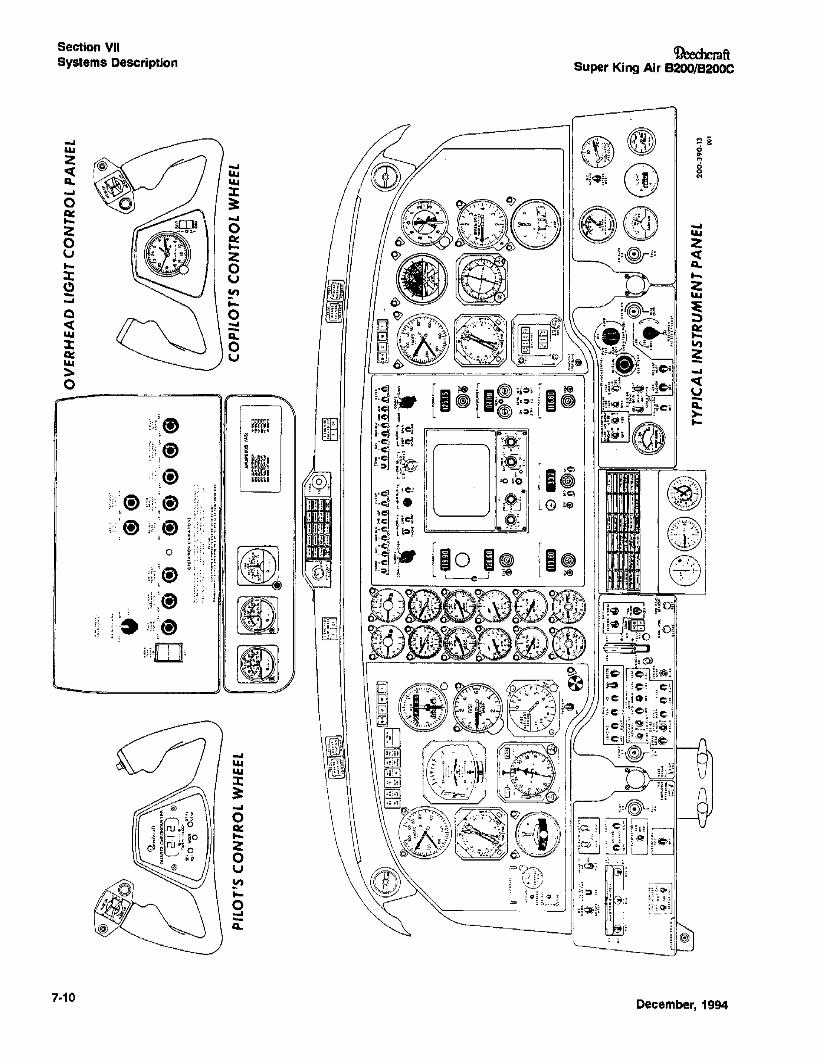
INSTRUMENT PANEL
The floating instrument panel design allows the flight instruments to be arranged in a group directly in front of the pilotand the copilot. Complete pilot and copilot flight instrumentation is installed, including dual navigation systems, twocourse indicators, dual gyro horizons, and dual turn and slipindicators.
The operation and use of the instruments, lights, switches,and controls located on the instrument panel is explainedunder the systems descriptions relating to the subject items.
ANNUNCIATOR SYSTEM
The annunciator system consists of a warning annunciatorpanel (with red readout) centrally located in the glareshield,and a caution/advisory annunciator panel (caution - yellow;advisory - green) located on the center subpanel. Two redMASTERWARNING flashers located in the glareshield (onein front of the pilot and one in front of the copilot) are a partof the system, as are two yeUow MASTER CAUTION flashers (located just inboard of the MASTER WARNING flashers), and a PRESS TO TEST button located immediately tothe right of the warning annunciator panel.
The annunciatorsare of the word-readout type. Whenever afault condition covered by the annunciator system occurs, asignal is generated and the appropriate annunciator is illuminated.
If the fault requires the immediate attention and reaction ofthe pilot, the appropriate red warning annunciator in thewarning annunciator panel illuminates and both MASTERWARNING flashers begin flashing. Any illuminated lens inthe warning annunciator panel will remain on until the faultis corrected. However, the MASTER WARNING flasherscan be extinguished by depressing the face of either MASTER WARNING flasher, even if the fault is not corrected. Insuch a case, the MASTER WARNING flashers will again beactivated if an additional warning annunciator illuminates.When a warning fault is corrected, the affected warningannunciator will extinguish, but the MASTER WARNINGflashers will continue flashing until one of them isdepressed.
7-6
'DeechcraftSuper King Air B200/B200C
Whenever an annunciator-covered fault occurs that requiresthe pilot's attention but not his immediate reaction, theappropriate yellow caution annunciator in the caution/advisory panel illuminates, and both MASTER CAUTIONflashers begin flashing. The flashing MASTER CAUTIONlights' can be extinguished by pressing the face of either 01the flashing lights to reset the circuit. SUbsequently, whenany caution annunciator illuminates, the MASTER CAUTION flashers will be activated again. An illuminated cautionannunciator on the caution/advisory annunciator panel willremain on until the fault condition is corrected, at which timeit will extingUish. The MASTER CAUTION flashers will continue flashing until one of them is depressed.
The caution/advisory annunciator panel also contains thegreen adVisory annunciators. There are no master flashersassociated with these annunciators, since they are onlyadvisory in nature, indicating functional situations which donot demand the immediate attention or reaction of the pilot.An advisory annunciator can be extingUished only by correcting the condition indicated on the illuminated lens.
The warning annunciators, caution annunciators, advisoryannunciators and yellow MASTER CAUTION flashers feature both a "bright" and a "dim" mode of illumination intensity. The "dim" mode wit be selected automatically whenever all of the follOWing conditions are met: a generator is onthe line; the OVERHEAD FLOOD LIGHTS are OFF; thePILOT FUGHT LIGHTS are ON; and the ambient light levelin the cockpit (as sensed by a photoelectric cell located inthe overhead light control panel) is below a preset value.Unless all of these conditions are met, the "bright" mode willbe selected automatically. On later airplanes, and earlierairplanes with modified annunciator circuitry, The MASTERWARNING flasher also features both a "bright" and "dim"mode of illumination.
The lamps in the annunciator system should be testedbefore every flight, and anytime the integrity of a lamp is inquestion. Depressing the PRESS TO TEST button, locatedto the right of the warning annunciator panel in the glareshield, illuminates all the annunciator lights, MASTERWARNING flashers, and MASTER CAUTION flashers. Anylamp that fails to illuminate when tested should be replaced(refer to LAMP REPLACEMENT GUIDE in Section VIII,HANDLING, SERVICING AND MAINTENANCE).
December, 1994
cneemcraftSuper King Air B200/B200C
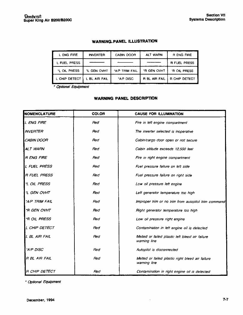
WARNING-PANEL ILLUSTRATION
Section VIISystems Description
L ENG FIRE INVERTER CABIN DOOR ALT WARN R ENG FIRE
L FUEL PRESS R FUEL PRESS
*l OIL PRESS *l GEN OVHT *AlP TRIM FAil *R GEN OVHT *R Oil PRESS
l CHIP DETECT L Bl AIR FAIL *A/P DISC R BL AIR FAil R CHIP DETECT
it Optional Equipment
WARNING PANEL DESCRIPTION
NOMENCLATURE COLOR CAUSE FOR ILLUMINAnON
L ENG FIRE Red Fire in left engine compartment
INVERTER Red The inverter selected is inoperative
CABIN DOOR Red Cabin/cargo door open or not secure
ALT WARN Red Cabin altitude exceeds 12,500 feet
R ENG FIRE Red Fire in right engine compartment
L FUEL PRESS Red Fuel pressure failure on left side
R FUEL PRESS Red Fuel pressure failure on right side
·L OIL PRESS Red Low oil pressure left engine
·L GEN OVHT Red Left generator temperature too high
·AlP TRIM FAIL Red Improper trim or no trim from autopilot trim command
·R GEN OVHT Red Right generator temperature too high
·R OIL PRESS Red Low oil pressure right engine
L CHIP DETECT Red Contamination in left engine oil is detected
L BL AIR FAIL Red Melted or failed plastic left bleed air failurewarning line
·A/P DISC Red Autopilot is disconnected
R BL AIR FAIL Red Melted or failed plastic right bleed air failurewarning line
R CHIP DETECT Red Contamination in right engine oil is detected
• Optional Equipment
December, 1994 7-7
Section VIISystems Description
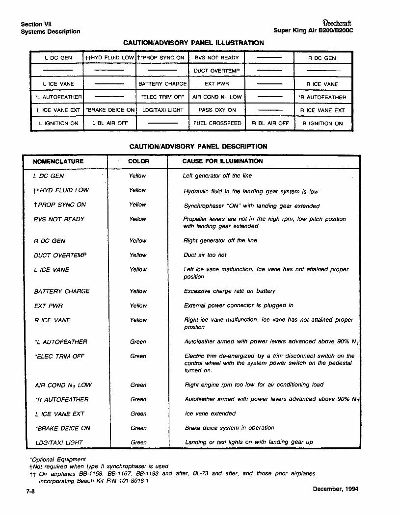
eAunoN/ADVISORY PANEL ILl.USTRAnON
OeechcmftSuper King Air B200/B20OC
L DC GEN ttHYD FLUID LOW t ·PROP SYNC ON RVS NOT READY R DC GEN
DUCT OVERTEMP
L ICE VANE BATTERY CHARGE EXT PWR R ICE VANE
-L AUTOFEATHER *ELEC TRIM OFF AIR COND N1 LOW -R AUTOFEATHER
L ICE VANE EXT -BRAKE DEICE ON LDGITAXI LIGHT PASS OXY ON R ICE VANE EXT
L IGNITION ON L BL AIR OFF FUEL CROSSFEED R Bl AIR OFF R IGNITION ON
CAUTION/ADVISORY PANEL DESCRIPTION
NOMENCLATURE COLOR CAUSE FOR ILLUMINAnON
L DC GEN Yellow Left generator off the line
ttHYD FLUID LOW Yellow Hydraulic fluid in the landing gear system is low
t PROP SYNC ON Yellow Synchrophaser "ON" with landing gear extended
RVS NOT READY Yellow Propeller levers are not in the high rpm, low pitch positionwith landing gear extended
R DC GlEN Yellow Right generator off the line
DUCT OVERTEMP Yellow Duct air too hot
L ICE VANE Yellow Left ice vane malfunction. Ice vane has not attained properposition
SATTERY CHARGE Yellow Excessive charge rate on battery
EXT PWR Yel/ow External power connector is plugged in
R ICE VANE Yel/ow Right ice vane malfunction. Ice vane has not attained properposition
-L AUTOFEATHER Green Autofeather armed with power levers advanced above 90% N1
-ELEC TRIM OFF Green Electric trim de-energized by a trim disconnect switch on thecontrol wheel with the system power switch on the pedestalturned on.
AIR COND N 1 LOW Green Right engine rpm too low for air conditioning load
*R AUTOFEATHER Green Autofeather armed with power levers advanced above 90% N1
L ICE VANE EXT Green Ice vane extended
*BRAKE DEICE ON Green Brake deice system in operation
LDGITAXI LIGHT Green Landing or taxi lights on with landing gear up
*Optional EquipmenttNot required when type II synchrophaser is usedtt On airplanes 88-1158, 88-1167, 88-1193 and after, BL-73 and after, and those prior airplanes
incorporating Beech Kit PIN 101-8018-1
7-8 December, 1994
Ci?eechcmftSuper King Air B200/B200C
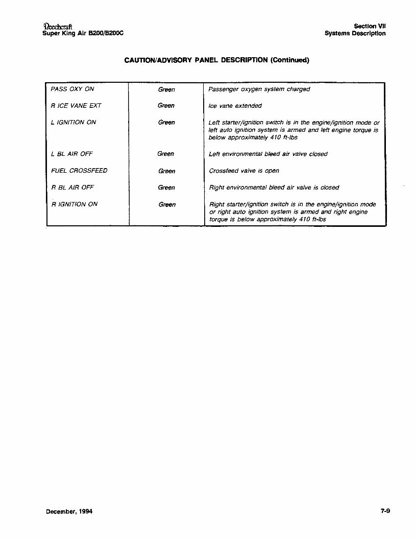
CAUTION/ADVISORY PANEL DESCRIPTION (Continued)
Section VIISystems Description
PASS OXY ON Green Passenger oxygen system charged
R ICE VANE EXT Green Ice vane extended
L IGNITION ON Green Left starter/ignition switch is in the engine/ignition mode orleft auto ignition system is armed and left engine torque isbelow approximately 410 ft-Ibs
L BL AIR OFF Green Left environmental bleed air valve closed
FUEL CROSSFEED Green Crossfeed valve is open
R BL AIR OFF Green Right environmental bleed air valve is closed
R IGNITION ON Green Right starter/ignition switch is in the engine/ignition modeor right auto ignition system is armed and right enginetorque is below approximately 410 ft-Ibs
December, 1994 7-9
OV
ER
HE
AD
LIG
HT
CO
NTR
OL
PA
NE
L~ . ..... o
,''\
'...
.'1
·...
'·
...4
101"
":'8:="
"8'''8'
'S..~
...~'':(f)
'0.,~..
..~...,~
..':(fi
''tt',·.\
I··••II
C,&.~
I.I
"·U
\.·(
.·,O
'.,·
..."
'(6
e#
..."·'..
..,o(.~_
,~
·'C
••IIII
.'•••
(',..Oo'O
..~·,c.
..
tntn
'<C
D21
9-CD
_.
:Ig
fn<
c=
I: n .. -S o ~
PIL
OT'
SC
ON
TRO
LW
HEE
L
~'~
...o~.".
........
.,
lO0
,~
ItIO
'II
•
•o
OC
.'S
".o
oc
'$..
...""
...
•9.•
.·.
90
.....
90.•
...
AIR
SPEE
DS
(lA
S)
I::=-~
==....1\LLe.-~
"'o
e..
...._...
.-...-
..
CO
PIL
OT'
SC
ON
TRO
LW
HEE
L
tn c i .. ~ ~. ~ ::;" Ir ~J 8~
200·
390-
13 001
~"".<.
to1.
a(~~",
~~~~.
':~l~~~
TYP
ICA
LIN
STR
UM
EN
TP
AN
EL
~ Q:E
J~ ~
-----=
--yr~I_III:'(~~
~~..
:=",.,,:
'::.;;;
;'c@
~tlttO;1
~'~'111I~"~',
(.C
Ull
...
.,....
,.1(...
'l"_
(CUI
.....ow
...
kJrt
"'1
.
,'I
~'tt'"
.'"~.
~."
~~o~~c#m
~~,Q,
iiit6
.!LO
li9~~
~~
'-,'~i-
ir.'k
~';':
@~.:f
li-'
~~~
r-~'-'
r-~I-,
~~~
mm~~lO
~iqJ"':"~
~..',I
_.
r'lW
<SI'O
IQR
,I.'.'
1':'f,
".".~,~
__
<.~~
~~\..
~>.i~
~.r'
i'lt
,0
~'.'Ji
iti~~o~
~~:""~:
~:~
Lq..
O'';,I~r'R':
:on
:,~®
,'!.!!
Po
'---__
~.~.~~
"~'~..~~
::It~~~
":;I~
I•
~.!I'
~\9~~
$~
$D~g
~i
lI"i"
C m n CD 3 a m .:" .... CD CD ~
i :I en wi .. -0 -s,::
Jo~
::1
-I11 CO ~ ..
200-
390-
12
un
'..
,t"\I~I':'-
-0
~t",I
n,I
n
!"!f
'.!!
~<;
'<~~
~~!
-lIllH
TI
.~-...-----W
~!!.
!!
!.!,
!!••
00(1
~..
..'O
w..
!All
.....
1
{i'!
!II!
i++
!!~ii
ii
'0'~c
'~i>
,""""OIO'·.
..llltC
-'~I
!>!
"'1,..,.
,:....,....
.,'i
Ci.,,"'"'
c!!
!'0
1W
#'''0'
~----a.---o-~---'~~
i'.
toIC
',c,..
,.
oI~
o
~P
OS
ITIO
NS
RE
SE
RV
ED
~F
OR
OP
TIO
NS
SH
OW
N
~'l'
:::'~
~'.
oooe
"""
.."
.,,,.,
..,....
RIG
HT
SID
EP
AN
EL
rI
--------'\
.\
\\,
PE
DE
ST
AL
\
AU
TOP
ILO
T/FL
IGH
TD
IRE
CTO
R
----fU
ll
SY
SflM
elle
un..
.AKIU----~
t,~,',
!,!?
<t?,I
I!..0
".~W,
'va
'..:
'••
•w
"."
••II
••t.
.:'
tv.'~
n\
CtO
'"
---lln
---J
~"OH'---
..J,
m~:"
,
FU
EL
CO
NT
RO
LP
AN
EL
c 3 CD a 0
CD ~ - I ~ ...
Section VIISystems Description
GROUND CONTROL
Direct linkage from the rudder pedals allows for nose wheelsteering. When the rudder control is augmented by a mainwheelbrake, the nose wheel deflection can be considerablyincreased.
The minimum wing-tip turning radius, using partial brakingaction and differential engine power, is 39 feet 10 inches.
FLAPS
Two flaps are installed on each wing. Power is deliveredfrom an electric motor to a gearbox mounted on the forwardside of the rear spar. The gearboxdrives four flexible driveshafts which are connected to jacksaews, one of whichoperates each flap. The motor incorporates a dynamic braking system, through the use of two sets of motor windings.This feature helps prevent overtravel of the flaps. A safetymechanism is provided to disconnect power to the electricflap motorin the event of a malfunction which would causeany flap to be three to six degrees out of phase with theother flaps.
The flaps are operated by a sliding switch handle on thepedestal just below the condition levers. Flap travel, from0% (full up) to 100% (full down) is registered on an electricindicator on top of the pedestal. A side detent provides forquick selection of the APPROACH position (400.4 flaps).From the UP position to the APPROACH position, the flapscannot be stopped in an intermediate position. BetweenAPPROACH and DOWN, the flaps can be stopped anywhere by moving the handle to the DOWN position until theflaps reach the desired position, then moving the flap-switchhandleback to APPROACH. Theflaps can be raised to anyposition between DOWN and APPROACH by raising thehandle to UP until the desired setting is reached, thenreturning the handle to APPROACH. Selecting theAPPROACH position will stop flap travel anytime the flapsare deflected more than 40010.
The flap-motor power circuit is protected by a 2o-ampereflap-motor circuit breaker placarded FLAPMOTOR, locatedon the left circuit breakerpanel belowthe fuel control panel.A 5-ampere circuit breaker for the control circuit (placardedFLAP CONTROL) is also located on this panel.
Lowering the flaps will produce these results:
ATIlTUDE - Nose UP
AIRSPEED - Reduced
STALL SPEED- Lowered
TRIM - Nose-Down Adjustment ReqUired to Maintain Attitude
LANDING GEAR
MECHANICAL LANDING GEAR
A 28-volt motor and gear box, located on the forward side 01the center-section main spar, extends and retracts the land
I ing gear. The landing gear motor is controlled by the handle
7·12
OeedtcraftSuper King Air B200/B200C
placarded LOG GEAR CONTROL- UP - ON on the pilot'sIright subpanel. The landing gear control handle must bepulled out of a detent before it can be moved from either theUP or the ON position. The motor incorporates a dynamicbraking system controlled with "up" and "down" limitswitches, which in conjunction with the landing gear lockingmechanism prevents overtravel of the landing gear.
Torque shafts drive main gear actuators. and duplex chainsdrive the nose gear actuator. A spring-loaded friction-typeoverload clutch in the gearbox prevents damage to thestructure and to the torque shafts in the event of a malfUnction. A 150 amp limiter, located on the landing gear panelforward of the main spar under the center floorboard, protects the system from electrical overload.
The Beech air-oil type shock struts are filled with compressed air and hydraulic fluid. Unkagefrom the rudder pedals permits nose wheel steering when the nose gear isdown. One spring-loaded link in the system absorbs some ofthe force applied to any of the interconnected rudder pedalsuntil the nose wheel is rolling, at which time the resistingforce is less and more pedal motion results in more nosewheel deflection .. Since motion of the pedals is transmittedvia cables and linkage to the rudder, rudder deflectionoccurs when force is applied to any of the rudder pedals.With the nose landing gear retracted, some of the forceapplied to any of the rudder pedals is absorbed by thespring-loaded link in the steering system so that there is nomotionat the nose wheel, but rudder deflection still occurs.The nose wheel is self centering upon retraction.
When force on the rudder pedal is augmented by a mainwheel braking action, the nose wheel deflection can be considerably increased.
A safety switch on the right main gear torque knee opensthe control circuit when the strut is compressed. The safetyswitch also activates a solenoid-operated down-lock hookon the landing gear control handle located on the pilot's right Isubpanel. This mechanism prevents the landing gear controlhandle from being raised when the airplane is on theground. The hook automatically unlocks when the airplaneleaves the ground. In the event of a malfunction of thedown-lock solenoid, the down lock can be released bypressing downward on the red down-lock release button.The release button is located Just left of the landing gear Icontrol handle. The landing gear control handle shouldnever be moved out of the ON detent while the airplane ison the ground; if it is, the landing gear warning hom willsound intermittently and the red gear-in-transit lights in thelanding gear control handle will illuminate (provided the IMASTER SWITCH is ON), warning the pilot to return thehandle to the ON position.
Visual indication of landinggear position is provided by individual green GEAR DOWN annunciators placarded NOSE -IL - R on t~e p!lot's right sUb~anel. The annunciators may bechecked In flight by pressing the annunciator. Two red,parallel-wired indicator lights located in the control handleilluminate to show that the gear is in transit or not locked.They also illuminate when the landing gear warning horn isactuated. Absence of illumination indicates that the gear is Iup and locked or down and locked. The red control handle
April, 1996
~ftSuper King Air B200/B20OC
IliQhts may be checked .bYpressing the HDL LT TEST buttonlocated to the right of the landing gear control handle.
LANDING GEARWARNING SYSTEM(MECHANICAL SYSTEM)
The landing gear warning system is provided to warn thepilot that the landing gear is not down and locked duringspecific flight regimes. Various warning modes result,depending upon the position of the flaps.
I
With the flaps in the UP or APPROACH position and eitheror both power levers retarded below approximately 80% N1,the warning hom will sound intermittently and the landinggear control handle lights will illuminate. The hom can besilenced by pressing the WARN HORN silence button adja-
Icent to the landing gear control handle; the lights in thelanding gear control handle cannot be cancelled. The landing gear warning system will be rearmed if the powerlever(s) are advanced sufficiently.
IWith the flaps beyond the APPROACH position, the warninghom and landing gear control handle lights will be activatedregardless of the power settings, and neither can be cancelled.
MANUAL LANDING GEAR EXTENSION(MECHANICAL SYSTEM)
Manual landing gear extension is provided through a separate, chain-drive system. To engage the system, pun theLOG GEAR RELAY circuit breaker, located to the left of thelanding gear control handle on the pilot's right subpanel, andensure that the landing gear control handle is in the ONposition. Pull up on the altemate engage handle (located onthe floor) and tum it clockwise until it stops. This will electrically disconnect the motor from the system and lock the alternate drive system to the gear box. With the altemate drivelocked in, the chain is driven by a continuous-aetion ratChet,which is activated by pumping the altemate extensionhandle located adjacent to the alternate engage handle.Stop pumping when all three green gear-down annunciatorsare illuminated. Further movement of the handle could damage the drive mechanism and prevent subsequent electricalgear retraction. Refer to LANDING GEAR MANUALEXTENSION (MECHANICAL SYSTEM) in Section IliA,ABNORMAL PROCEDURES. If any of the following conditions exist, it is likely that an unsafe gear indication is due toan unsafe gear and is not a false indication.
1. The inoperative gear down annunciator illuminateswhen tested.
2. The red light in the handle is illuminated.
3. The gear warning hom sounds when one or both powerlevers are retarded below a preset N1.
After a praeti~ manual extension of the landing gear, thegear may be retracted electrically. Refer to LANDING GEARRETRACTION AFTER PRACTICE MANUAL EXTENSION(MECHANICAL SYSTEM) in Section IV, NORMAL PROCEDURES.
HYDRAUUC LANDING GEAR
The retractable tricycle landing gear is electrically controlledand hydraulically actuated. The system utilizes foldingbraces, called drag legs, that lock in place when the gear is
April, 1996
Section VIISystems Description
fully extended. The nose gear actuator incorporates an inter-Inal mechani~ down-lock. to hol~ the gear in the fullyextended position. The masn gear Incorporate mechanicallocks on the drag leg and no locks on the actuators. Thelanding gear is held in the up-lock position by hydraulic pressure.
Hydraulic pressue to the system is supplied by a hydraulicpower pack. A hydraulic reservoir located in the left centerwing section provides hydraulic fluid to the power pack. Thereservoir incorporates a dip stick to provide a visual check offluid level.
Electrically actuated control valves control the flow ofhydraulic fluid to the individual gear actuators. The controlvalves receive electrical power through the landing gearcontrol handle. IAccidental retraction of the landing gear is preventedthrough safety switches located on the main landing gears.
LANDING GEAREXTENSION ANDRETRACTION (HYDRAUUCSYSTEM)The nose and main landing gear assemblies are extendedand retracted by a hydraulic power pack in conjunction withhydraulicactuators. The hydraulic power pack is located inthe left center section, just forward of the main spar. Onehydraulic actuator is located at each landing gear. Thepower packconsists of: a hydraulic pump, a 28VDC motor,a two section fluid reservoir, filter screens, gear selectorvalve, two solenoids, a fluid level sensor, and an up-lockpressure switch. For manual extension the system has ahand-Iever-operated pump located on the floor between thecrew seats. Hydraulic lines, one for normal extension, andone for retraction, routed from the power pack, and one formanual extension from the hand pump, are routed to the Inose and main gear actuators. The normal extension linesand the manual extension lines are connected to the upperend of each hydraulic actuator. The hydraulic lines forretraction are fitted to the lower ends of the actuators.Hydraulic fluid under pressure generated by the power packpump and contained in the aca.mulator acts on the pistonfaces of the actuators which are attached to folding dragbraces resulting in the extension or retraction of the landinggear.
An internal mechanical lock in the nose gear actuator andthe over-center action of the nose gear drag leg assemblylock the nose gear in the down position. Notched hook, locklink and lock link guide attachments fitted to each main gearupper drag leg provide positive down-lock action for themain gear.
Electrical overload to the system is prevented through theuse of a 60 ampere circuit breaker located below the flooring near the hydraulic power pack.
The landing gear hydraulic power pack motor is controlledby the use of the landing gear control handle placarded LOGIGEAR CONTROL - UP - ON located on the pilot's subpanel.The control handle must be pulled out of a detent before itcan be moved from either the UP or ON position.
Safety switches, called squat switches, on the main geartorque knees open the control circuit when the strut is compressed. The squat switches must close to actuate a solenoid which moves a down-lock hook on the landing gear I
7·13
Section VIISystems Description
Icontrol handle to the releasedposition.This mechanism prevents the landing gear control handle from being placed inthe UP position when the airplane is on the ground. Thehook automatically disengageswhen the airplaneleavestheground, and can be overridden by pressing down on the red
Idown-lock release button located to the left of the landinggear control handle.
In flight, as the landing gear movesto the full down position,the down lock switches are actuated and interrupt current to
Ithe pump motor. When the red gear in-transit lights in thelanding gear control handle extinguish and the three greenGEAR DOWN annunciators illuminate, the landinggear is inthe fully extended position.
Two gear-select solenoids locatedon the valve body of thepump are energized through positioning of the landing gearcontrol switch handle either to the UP or ONposition. Onceenergized, the gear select valve is actuated, allowinghydraulic fluid to flow to the actuators.
Hydraulic system pressure performs the up-lock function,holding the landing gear in the retracted position. When thehydraulic pressure reaches 2775 :55 psi, the up-lock pressure switch will cause the landing gear relay to open andinterrupt the current to the pump motor. The same pressureswitch will cause the pump to actuate, should the hydraulicpressure drop to approximately 2400 psi.
A caution annunciator, placarded HYD FLUID·LOW, in thecaution/advisory annunciator panel will illuminate (yellow)whenever the hydraulic fluid level in the hydraulic power
Ipack is low. The annunciator is tested by pressingthe HYDFLUID SENSOR TEST button located on the pilot's subpanel.
I The landing gear control handleshould never be moved outof the ON detent while the airplane is on the ground. If it is,the landing gear warning hom will sound intermittently, and
Ithe red gear-in-transit lights in the landing gear controlhandle will illuminate (provided the MASTER SWITCH isON), warning the pilot to retum the handle to the ON position.
Landing gear position is indicatedby an assembly of threegreen annunciators. When illuminated, the annunciatorsindicate that the particular gear is down. Absence of illumination indicates that the gear is up.
Two red parallel-wired indicator lights, located in the landinggear control handle, illuminate to show that the gear is intransit or unlocked. The red lights in the handle also illuminate when the landing gear warning hom is actuated.
The red lights may be checked by pressing the HDL LTTEST button located adjacent to the landing gear controlhandle.
7·14
OeechcmftSuper King Air B200/B200C
LANDING GEAR WARNING SYSTEM(HYDRAULIC SYSTEM)
The landing gear warning system is provided to warn thepilot that the landing gear is not down during specific flightregimes. Variouswarningmodes result, depending upon thepositionof the flaps.
With the flaps in the UP or APPROACH position and eitheror both power leversretardedbelow approximately 80% N1,the waming hom will sound intermittently and the landinggear control handle lights will illuminate. The hom can besilenced by pressing the WARN HORN silence button adjacent to the landing gear control handle; the lights in thelanding gear control handle cannot be cancelled. The landing gear warning system will be rearmed if the powerlever(s) are advanced sufficiently. .
With the flaps beyond APPROACH position, the warning Ihom and landinggear switch handle lights will be activatedregardless of the power settings, and neither can be cancelled.
MANUAL LANDING GEAR-EXTENSION(HYDRAULIC SYSTEM)
An alternate extension handle, placarded LANDING GEARALTERNATE EXTENSION, is located on the floor on thepilot's side of the pedestal. To engage the system, pull theLANDING GEAR RELAY circuit breaker, located to the leftof the landing gear control handle on the pilot's right subpanel, and ensurethat the landing gear control handle is inthe ON position. Remove the alternate extension handlefromthe securingclip and pump up and down. While pumping, do not lower the handle below the level of the securingclip during the down stroke as this will allow accumulatedhydraulicpressure to bleed off. Continuethe pumping actionuntil the three green gear-down annunciators are illuminated, then stow the handle in the securing clip. If one ormore gear down annunciators do not illuminate, the alternatehandle must not be stowed. Instead, leave it at the topof the up stroke. Continue to pump the handle when conditions permit until the gear is mechanically secured afterlanding. Referto LANDING GEAR MANUAL EXTENSION inSection lilA, ABNORMAL PROCEDURES. If any of the followingconditions exist, it is likely that an unsafe gear indication is dueto an unsafegear and is not a false indication.
1. The inoperative gear down annunciator illuminateswhentested.
2. The red light in the handle is illuminated.3. The gearwaminghom sounds when one or both power
levers are retarded below a preset N1.
After a practice manual extension of the landing gear, thegear may be retracted hydraUlically. Refer to LANDINGGEAR RETRACTION AFTER PRACTICE MANUALEXTENSION in Section IV, NORMAL PROCEDURES.
April, 1996
OeechcmftSuper King Air B200/B200c
BRAKE SYSTEM
The dual hydraulic brakes are operated by depressing thetoe portion of either the pilot's or copilot's rudder pedals.The series system plumbing enables braking by either pilotor copilot.
Dual parking-brake valves are installed adjacent to the rudder pedals between the master cylinders of the pifot's rudderpedals and the wheel brakes. A control for the valves, placarded PARKING BRAKE, is located below the pilot's leftsubpanel. After the pilot's brake pedals have beendepressed to build up pressure in the brake lines, bothvalves can be closed simultaneously by pulling out the parking brake handle. This retains the pressure in the brakelines. The parking brake is released by depressing the pedals briefly to equalize the pressure on both sides of thevalve, then pushing in the parking brake handle to open thevalve.
The parking brake should be left off andwheel chocks installed if the airplane is to beleft unattended. Changes in the ambient temperature can cause the brakes to release orto exert excessive pressures.
TIRES
The airplane is normally equipped withdual 18x5.5 Type VII,8-ply-rated, tubeless, rim-inflated tires on each main gear.For increased service life, 10-ply-rated tires of the same sizemay be installed.
Optionally, the airplane may be equipped with dual 22x6.7510, 8-ply-rated, tubeless tires on each main gear. Thesetires provide higher flotation, and permit operation atapproximately 2/3 the inflation pressure required for thestandard 18x5.5 tires.
The nose gear is equipped with a 22x6.75-10, a-ply-rated,tubeless tire.
BAGGAGE COMPARTMENT
The entire aft-cabin area (which is aft of the foyer) maybeutilized as a baggage compartment. A nylon web is providedfor the restraining of loose items. See "Dimensional andLoading Data" and "Cabin Arrangement Diagrams" in Section VI, WEIGHT AND BALANCEJEQUIPMENT UST.
I WARNING IUnless authorized by applicable Departmentof Transportation Regulations, do not carryhazardous material anywhere in the airplane.
April, 1996
Section VIISystems Description
Do not carry children in the baggage compartment unless secured in a seat.
Baggage and other objects should besecured by webs in order to prevent shiftingin turbulent air.
Items stowed in the aft-cabin area are accessible in flight.The aft-cabin area can be closed off from the foyer by pulling the optional baggage compartment curtain across theopening and securing it with the snap fasteners provided.Alternately, a latching compartment door may be installed.The door is unlatched by rotating the latch handle clockwise,and latched by rotating the handle counterclockwise.
SEATS, SEATBELTS, AND SHOULDERHARNESSES
SEATS
COCKPIT
The pilot and copilot seats are adjustable fore and aft, aswelf as vertically. When the release lever under the frontinboard comer of the seat is lifted, the seat can be movedforward or aft as required. When the release lever under thefront outboard corner of the seat is lifted and no weight is onthe seat, the seat will rise in half-inch increments to its highest position. When weight is on the seat and 'the lever islifted, the seat will slowlymove downward in half-inch increments until the lever is released, or until the seat reaches itslowest point of vertical travel. The armrests pivot at the aftend and can be raised to facilitate entry to and egress fromthe seats.
CABIN
Various configurations of passenger chairs and 2- or 4-placecouches may be installed on the continuous tracks whichare mounted on the cabin floor. All passenger chairs areplacarded either FRONT FACING ONLY or FRONT OR AFTFACING on the horizontal leg cross brace. Only chairs placarded FRONT OR AFT FACING may be installed facing aft.All aft-facing chairs (and all forward-facing chairs that areequipped with shoulder harnesses) are equipped withadjustable headrests.
WARNING IBefore takeoff and landing, the headrestshould be adjusted as required to providesupport for the head and neck when the passenger leans against the seatback.
7-15
Section VIISystems Description
Some passenger chairs can be moved fore and aft, to suitlegroom requirements of different passengers, by lifting ahorizontal release lever that extends laterally under the frontof adjustable seats. ("Front" is the direction opposite theseatback, regardless of whether the chair faces fore or aft)
The seatbacks can be adjusted to any angle from fullyupright to fully reclining, by depressing the release leverlocated on the side of the seat at the front inboard comer.When the lever is depressed and the passenger leansagainst the seatback, the seatback will slowly recline untilthe lever is released, or until the fully reclining position isattained. When no weight is placed against the seatbackand the lever is depressed, the seatback will rise until thelever is released, or until the fully upright position is reached.The seatbacks of all occupied seats must be upright fortakeoff and landing.
The passenger-chair seatback can also be folded flat overthe seat cushion, after releasing the lock lever located onthe side of the seat at the back inboard comer.
The optional lateral-tracking passenger chairs incorporate aflat, rectangular release lever undemeath the front inboardcomer of the seats. When this lever is lifted, the chairs canbe adjusted fore and aft, as well as laterally. The seatbackadjustments are the same as those on the standard passenger chairs. When occupied, these seats must be in the outboard position (i.e., against the cabin Wall) for takeoff andlanding.
Inboard armrests on passenger chairs - and both armrestson couches and lateral-tracking chairs - can be folded flushwith the top of the seat cushions to facilitate entry to andegress from the seat. The armrests can be lowered by liftingthe flat, rectangular release plate located under the front endof the armrest, then moving the armrest toward the front ofthe seat and downward. The armrest can be raised by pulling the armrest upward and toward the seatback until itlocks into place.
The couches are not adjustable.
FOYER
Hinged seat-cushion halves mounted on top of the toiletform an extra passenger seat when the toilet is not is use.
AFT-CABINAREA
One or two optional folding seats may be installed in the aftcabin area They are mounted on the cabin sidewall andswing inboard when unfolded. A latch mechanism on the leglocks the seats in place when they are unfolded. When thisseating is not needed, the seat(s) may be folded against thecabin sidewall and held in place with retaining straps.
7·16
~Super King Air B200/B200c
SEATBELTS
Every seat in the airplane is equipped with a seatbelt. Theseatbelt can be lengthened by turning the male half of thebuckle at a right angle to the belt, then pulling the male halfin the direction away from the anchored end of the belt Thebuckle is locked by sliding the male half into the female halfof the buckle. The belt is then tightened by pulling the shortend of the belt through the male half of the buckle until asnug fit is obtained. The buckle is released by lifting thelarge, hinged release lever on the female buckle half andpulling the male half of the buckle free. All occupants mustwear seat belts during takeoff and landing.
SHOULDER HARNESSES
COCKPIT
The shoulder harness installations for the pilot and copilotseats consist of two straps each. Each strap is routed fromthe lower aft area of the seat, up the seatback, and througha retaining loop on top of the seatback. One strap is wornover each shoulder. Each strap terminates in a slottedbayonet-blade fastener which is aligned with one edge ofthe strap.When the two bayonet blades are placed together,the shoulder harness straps can be secured by sliding themale half of the seatbelt buckle through the bayonet slotsand into the female half of the seatbelt buckle.
The shoulder hamess straps proceed from inertia reels builtinto the crew chairs. Spring loading at the inertia reels keepsthe shoulder harnesses snug, but allows the pilot and copilot~II the freedom of movement normally required in flight.However, the inertia reels incorporate a locking device thatwill secure the harness straps in the event of sudden forward movement.
CABIN
The shoulder harness on passenger chairs consists of asingle strap. It is routed through the top of the seatback andterminates in a triangular metal fastener. The strap is worndiagonally. It runs from the outboard shoulder to the inboardhip area, where it is secured by hooking the metal fasteneraround the securing stud on the male half of the seatbeltbuckle.
The shoulder hamess strap coils and uncoils from an inertiareel built into the passenger chair. Spring loading at theinertia reel keeps the shoulder harness strap snug, butallows considerable freedom of movement However, theinertia reel incorporates a locking device that will secure theharness strap in the event of sudden forward movement. Ifthe seat is equipped With a shoulder hamess, it must beworn during takeoff and landing.
April, 1996
- OeechcmftSuper· King Air B200/B200C
I WARNING IEnsure the seatback is in the fully uprightposition and that the headrest is properlyadjusted whenever the shoulder harness isused.
AFT-CABIN AREA
The shoulder harness for the aft-cabin area fOld-up chairs isof a double-strap configuration. The middle portion of thestrap is secured by a metal slip ring which is anchored to theaft pressure bulkhead. The two ends (Which adually fundionas two separate straps) extend downward toward theseatbelt-buckle area. One end of the shoulder harness strap
December, 1994
Section VIISystems Description
terminates in a slotted bayonet-blade fastener. The otherend is attached to the upper edge of the shoulder harnessadjuster. A short adjusting strap. which is also equipped witha slotted bayonet blade fastener, extends upward from thearea of the seatbelt buckle and slides through the lower portion of the shoulder harness adjuster. A small, flexibleadjusting tab is also attached to the lower edge of the adjUSter.
One shoulder harness strap is worn over each shoulder.When the two bayonet blades are placed together. theshoulder harness straps can be secured by sliding the malehalf of the seatbelt buckle through the bayonet slots and intothe female half of the seatbelt buckle. The shoulder harnessstrap can be lengthened by grasping the tab on the adjusterand pulling upward. The strap can be tightened by graspingthe loose end of the adjusting strap and pUlling it through theadjuster until the shoulder harness is snug.
7-17
Section VIISystems Description
OeechcmftSuper King Air B200/B200C
8200-104-54
Whether unlocking the door from the outside or the inside.the release button adjacent to the door handle must be helddepressed before the handle can be rotated (counterclockwise from inside the airplane. clockwise from outside) tounlock the door. Consequently, unlocking the door is a twohand operation requiring deliberate action. The release button acts as a safety device to help prevent accidental opening of the door. As an additional safety measure, adifferential-pressure-sensitive diaphragm is incorporatedinto the release-button mechanism. The outboard side of thediaphragm is open to atmoshperic pressure. the inboardside to cabin air pressure. As the cabin-to-atmospheric pressure differential increases. it becomes increasingly difficultto depress the release button, because the diaphragmmoves inboard when either the outboard or inside releasebutton is depressed.
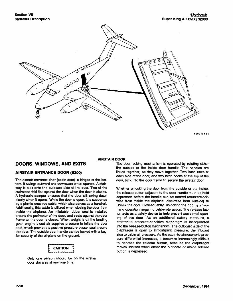
AIRSTAIR DOORThe door locking mechanism is operated by rotating eitherthe outside or the inside door handle. The handles arelinked together, so they move together. Two latch bolts ateach side of the door, and two latch hooks at the top of thedoor, lock into the door frame to secure the airstair door.
DOORS, WINDOWS, AND EXITS
AIRSTAIR ENTRANCE DOOR (8200)
The airstair entrance door (cabin door) is hinged at the bottom. It swings outward and downward when opened. A stairway is built onto the outboard side of the door. Two of thestairsteps fold flat against the door when the door is closed.A hydraulic damper ensures that the door will swing downslowly when it opens. While the door is open, it is supportedby a plastic-encased cable, which also serves as a handrail.Additionally. this cable is utilized when closing the door frominside the airplane. An inflatable rubber seal is installedaround the perimeter of the door. and seats against the doorframe as the door is closed. When weight is off the landinggear. engine bleed air supplies pressure to inflate the doorseal, which provides a positive pressure-vessel seal aroundthe door. The outside door handle can be locked with a key.for security of the airplane on the ground.
Only one person should be on the airstairdoor stairway at anyone time.
7-18 December, 1994
CReechcmft. Super King Air B200/B200C
IWARNING INever attempt to unlock or even check thesecurity of the door in flight.
If the CABIN DOOR annunciator illuminatesin flight, or if the pilot has any reason whatever to suspect that the door may not besecurely locked, the cabin should be depressurized (after first considering altitUde), andall occupants instructed to remain seatedwith their seat beIts fastened. After the airplane has made a full-stop landing and thecabin has been depressurized, a crew member should check the security of the cabindoor.
To close the door from outside the airplane, lift up the freeend of the airstair door and push it up against the door frameas far as possible. Then grasp the handle with one hand androtate it clockwise as far as it will go. The door will thenmove into the closed position. Then rotate the handle counterclockwise as far as it will go. The release button shouldpop out, and the handle should be pointing aft. Check thesecurity of the airstair door by attempting to rotate thehandle clockwise without depressing the release button; thehandle should not move.
To close the door from inside the airplane, grasp the handrail cable and pull the airstair door up against the doorframe. Then grasp the handle with one hand and rotate itcounterclockwise as far as it will go, continuing to pullinward on the door. The door will then move into the closedposition. Then turn the handle clockwise as far as it will go.The release button should pop out, and the handle shouldbe pointing down. Check the security of the door by attempting to rotate the handle counterclockwise without depressingthe release button; the handle should not move. Next, lift thefolded stairstep that is just below the door handle. A placardadjacent to the round observation window advises theobserver that the safety lock arm should be in positionaround the diaphragm shaft (plunger) when the handle is inthe locked position. The placard also presents a diagramshowing how the arm and shaft should be positioned. A redpush-button switch near the window turns on a lamp insidethe door, which illuminates the area observable through thewindow. If the arm is properly positioned around the shaft,proceed to check the indication in each of the visual inspection ports, one of which is located near each corner of thedoor. The green stripe painted on the latch bolt should bealigned with the black pointer in the visual inspection port. Ifany condition specified in this door-locking procedure is notmet, DO NOT TAKE OFF.
December, 1994
Section VIISystems Description
8200-107-27
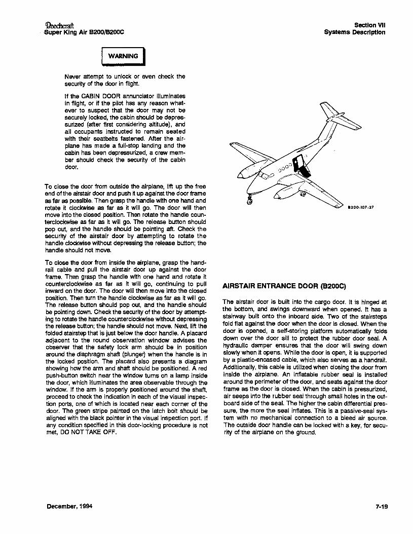
AIRSTAIR ENTRANCE DOOR (B200C)
The airstair door is built into the cargo door. It is hinged atthe bottom, and swings downward when opened. It has astairway built onto the inboard side. Two of the stairstepsfold flat against the door when the door is closed. When thedoor is opened, a self-storing platform automatically foldsdown over the door sill to protect the rubber door seal. Ahydraulic damper ensures that the door will swing downslowly when it opens. While the door is open, it is supportedby a plastic-encased cable. which also serves as a handrail.Additionally, this cable is utilized when closing the door frominside the airplane. An inflatable rubber seal is installedaround the perimeter of the door, and seats against the doorframe as the door is closed. When the cabin is pressurized,air seeps into the rubber seal through small holes in the outboard side of the seal. The higher the cabin differential pressure, the more the seal inflates. This is a passive-seal system with no mechanical connection to a bleed air source.The outside door handle can be locked with a key, for security of the airplane on the ground.
7-19
Section VIISystems Description
Only one person should be on the airstairdoor stairway at anyone time.
The door locking mechanism is operated by rotating eitherthe outside or the inside door handle, both of which movesimultaneously. Three hollow, crescent latches on each sideof the door rotate to capture or release latch posts mountedin the cargo door to secure the airstair door. When latched,the airstair door becomes an integral part of the cargo door.
Whether unlocking the door from the outside or the inside,the release button adjacent to the door handle must be helddepressed before the handle can be rotated (counterclockwise from inside the airplane, clockwise from outside) tounlock the door. Consequently, unlocking the door is a twohand operation requiring deliberate action. The release button acts as a safety device to help prevent accidental opening of the door. As an additional safety measure, adifferential-pressure-sensitive diaphragm is incorporatedinto the release-button mechanism. The outboard side of thediaphragm is open to atmoshperic pressure, the inboardside to cabin air pressure. As the cabin-te-atmospheric pressure differential increases, it becomes increasingly difficultto depress the release button, because the diaphragmmoves inboard when either the outboard or inside releasebutton is depressed.
WARNING INever attempt to unlock or even check thesecurity of the door in flight.
If the CABIN DOOR annunciator illuminates in flight, or if thepilot has any reason whatever to suspect that the door maynot be securely locked, the cabin should be depressurized(after first considering altitude), and all occupants instructedto remain seated with their seatbelts fastened. After the air-
7·20
OeechcraftSuper King Air B200/B200C
plane has made a full-stop landing and the cabin has beendepressurized. a crew member should check the security ofthe airstair door and the cargo door.
To close the door from outside the airplane, lift up the freeend of the airstair door and push it up against the door frameas far as possible. Then grasp the handle with one hand androtate it clockwise as far as it will go. The door will thenmove into the closed position. Then rotate the handle counterclockwise as far as it will go. The release button shouldpop out, and the handle should be pointing aft. Check thesecurity of the door by attempting to rotate the handle clockwise without depressing the release button; the handleshould not move.
To close the door from inside the airplane, grasp the handrail cable and pull the airstair door up against the doorframe. Then grasp the handle with one hand and rotate itcounterclockwise as far as it will go, continuing to pullinward on the door. The door will then move into the closedposition. Then turn the handle clockwise as far as it will go.The release button should pop out, and the handle shouldbe pointing down. Check the security of the door by attempting to rotate the handle counterclockwise without depressingthe release button; the handle should not move. Next. lift thesecond folded airstep below the door handle. A placardadjacent to the round observation window advises theobserver that the safety lock arm should be in positionaround the diaphragm shaft (plunger) when the handle is inthe locked position. The placard also presents a diagramshowing how the arm and shaft should be positioned. A redpush-button switch near the window turns on a lamp insidethe door, which illuminates the area observable through thewindow. If the arm is properly positioned around the shaft,proceed to check the orange stripe on each of the six rotarylatches (three on each side of the airstair door) and ensureeach is aligned with the notch in the plate on the door frame.Finally, turn the battery switch ON and check the warningannunciator panel in the cockpit; ensure that the red CABINDOOR annunciator is extinguished. It will illuminate whenthe battery switch is ON and the airstair door is not closedand securely latched. With the BATtery switch OFF and theairstair door closed but not latched, the CABIN DOORannunciator will illuminate. If any condition specified in thisdoor-latching procedure is not met, DO NOT TAKE OFF.
December, 1994
'iJeechcmft..Super King Air B200/B200C
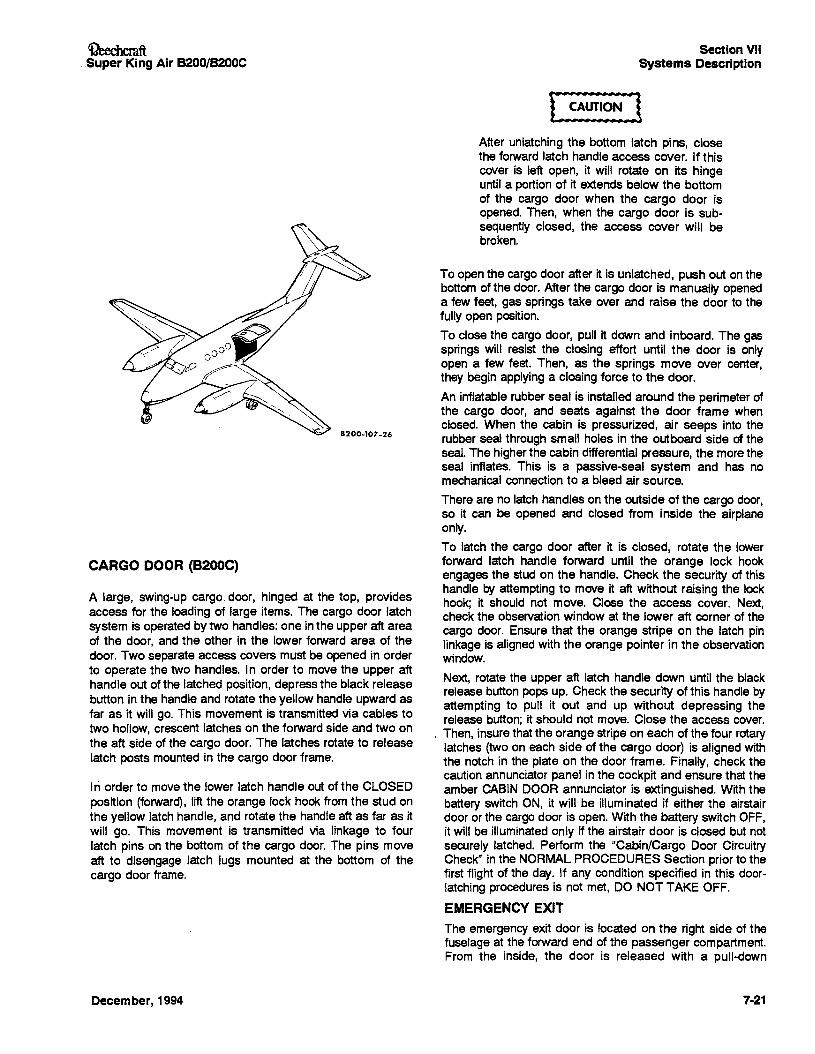
8200-107-26
CARGO DOOR (B200C)
A large, swing-up cargo. door, hinged at the top, providesaccess for the loading of large items. The cargo door latchsystem is operated by two handles: one in the upper aft areaof the door, and the other in the lower forward area of thedoor. Two separate access covers must be opened in orderto operate the two handles. In order to move the upper afthandle out of the latched position, depress the black releasebutton in the handle and rotate the yellow handle upward asfar as it will go. This movement is transmitted via cables totwo hollow, crescent latches on the forward side and two onthe aft side of the cargo door. The latches rotate to releaselatch posts mounted in the cargo door frame.
In order tomove the lower latch handle out of the CLOSEDposition (forward), lift the orange lock hook from the stud onthe yellow latch handle, and rotate the handle aft as far as itwill go. This movement is transmitted via linkage to fourlatch pins on the bottom of the cargo door. The pins moveaft to disengage latch lugs mounted at the bottom of thecargo door frame.
December, 1994
Section VIISystems Description
After unlatching the bottom latch pins, closethe forward latch handle access cover. If thiscover is left open, it will rotate on its hingeuntil a portion of it extends below the bottomof the cargo door when the cargo door isopened. Then, when the cargo door is subsequently closed, the access cover will bebroken.
To open the cargo door after it is unlatched, push out on thebottom of the door. After the cargo door is manually openeda few feet, gas springs take over and raise the door to thefully open position.
To close the cargo door, pull it down and inboard. The gassprings will resist the closing effort until the door is onlyopen a few feet. Then, as the springs move over center,they begin applying a closing force to the door.
An inflatable rubber seal is installed around the perimeter ofthe cargo door, and seats against the door frame whenclosed. When the cabin is pressurized, air seeps into therubber seal through small holes in the outboard side of theseal. The higher the cabin differential pressure, the more theseal inflates. This is a passive-seal system and has nomechanical connection to a bleed air source.
There are no latch handles on the outside of the cargo door,so it can be opened and closed from inside the airplaneonly.
To latch the cargo door after it is closed, rotate the lowerforward latch handle forward until the orange lock hookengages the stud on the handle. Check the security of thishandle by attempting to move it aft without raising the lockhook; it should not move. Close the access cover. Next,check the observation window at the lower aft corner of thecargo door. Ensure that the orange stripe on the latch pinlinkage is aligned with the orange pointer in the observationwindow.
Next, rotate the upper aft latch handle down until the blackrelease button pops up. Check the security of this handle byattempting to putl it out and up without depressing therelease button; it should not move. Close the access cover.
I Then, insure that the orange stripe on each of the four rotarylatches (two on each side of the cargo door) is aligned withthe notch in the plate on the door frame. Finally, check thecaution annunciator panel in the cockpit and ensure that theamber CABIN DOOR annunciator is extinguished. With thebattery switch ON, it will be illuminated if either the airstairdoor or the cargo door is open. With the battery switch OFF,it will be illuminated only if the airstair door is closed but notsecurely latched. Perform the "Cabin/Cargo Door CircuitryCheck" in the NORMAL PROCEDURES Section prior to thefirst flight of the day. If any condition specified in this doorlatching procedures is not met, DO NOT TAKE OFF.
EMERGENCY EXITThe emergency exit door is located on the right side of thefuselage at the forward end of the passenger compartment.From the inside, the door is released with a putt-down
7·21
Section VIISystems Description
handle, placarded EXIT-PULL. From the outside, the door isreleased with a flush-mounted, pull-out handle. The nonhinged, plug-type door removes completely from the frameinto the cabin when the latches are released.
8200:
The door can be locked so that it cannot be removed oropened from the outside using the flush-mounted pull-outhandle. The door is locked when the lock-lever (inside) is inthe down or locked position. Locking the door is for securitywhen the airplane is parked. The lock-lever should be in theup or unlocked position prior to flight, to allow removal of thedoor from the outside in the event of an emergency.Removal of the door from the inside is possible at all timesusing the EXIT-PULL handle, since this handle is not lockedby the lock-lever. An exit lock placard is placed on the lock- ,lever so that it can be read when the lever is in the lockedposition.
B200C:
The door can be locked with a key from the inside, to prevent opening from the outside. The inside handle will unlatchthe door, whether or not it is locked, by overriding the locking mechanism. The key lock should be unlocked prior toflight, to allow removal of the door from the outside in theevent of an emergency. The keyhole is in the horizontalposition when the door is 'locked. The key cannot beremoved in this position.
A wiper-type disconnect for the air duct that supplies air tothe eyeball outlet in the emergency exit door is located onthe upper-aft edge of the door. As the door is removed, theduet is disconnected, since it is an integral part of the door.
Located on the lower-forward edge of the door is an eledrical disconnect for the wiring that goes to the reading lightand the fluorescent light in the emergency exit door. It willunplug as the door is being removed. Upon reinstalling thedoor, the electrical disconnect should be reconnected before'movingthe door into the closed position.
INTERIOR DOORS
Sliding doors are provided between the cockpit and cabin,and between the cabin and foyer. These doors provide privacy, and prevent the spilling of light from one compartmentinto another. The doors are closed by sliding the twopartition-type door panels to the center of the aisle, wherethey are held together by a magnetic strip in the edge ofeach door.
CABIN WINDOWS
Each cabin window pane, which is composed of a sheet ofpolyvinyl butyraf (PVB) laminated between two sheets ofclear acrylic plastic, is stressed to withstand the cabin-toambient air pressure differential. It is then sealed into a window opening in the fuselage, and forms an integral part ofthe pressure vessel.
POLARIZED TYPE
Two dust panes are mounted inboard of the cabin windowpane in each window frame. Each of these dust panes iscomposed of a film of polarizing material laminated between
7-22
C1?eechcraftSuper King Air B200/B200C
two sheets of acrylic plastic. The inboard dust pane rotatesfreely in the window frame and has a protruding thumb knobnear the edge. Rotating the pane through an arc of 90° permits complete light regulation as desired. Rotation changesthe relative alignment betweenthe polariZing films, thus providing any degree of light transmission from full intensity toalmost none.
IWARNING IDo not look directly at the sun, even throughpolarized windows, because eye damagecould result.
When the airplane is to be parked in areasexposed to intense sunlight, the polarizedwindows should be rotated to the clear position to prevent deterioration of the polarization coating. Sufficient ultraviolet protection isprovided to prevent fading of the upholstery.
SHADE TYPE
A dust pane, which is a single sheet of tinted acrylic plastic,is mounted inboard of the cabin window pane in each window frame. An adjustable window shade is provided to control the amount of light admitted. The shade is adjusted bysqueeZing the two latch handles located on the lower centerof the shade, then positioning the shade as desired. Detentsin the shade tracks provide positive latching action at various positions.
SUNVISORS
OPERATING INSTRUCTIONS
TO OPERATE FROM STOWED POSITION:
Push straight back and pull down. Move along track todesired place and pivot out near windshield (or window),rotate knob clockwise to lock.
To change position:Rotate knob counterclockwise to unlock, move to desiredlocation and position, then relock knob by turning clockwise.
To stow:Rotate knob counterclockwise to unlock, move along trackto aft end, pivot up against headliner to allow catch to retainsunvisor assembly.
CONTROL LOCKS
The control locks consist of a U-shaped clamp and two pins,all connected by a chain. The pins lock the primary flightcontrols; the U-shaped clamp fits around the engine control
December, 1994
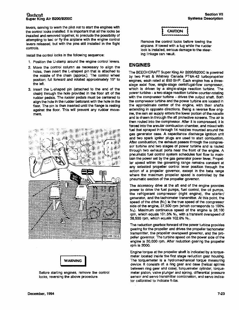
~ftSuper King Air B200/B200C
levers, serving to warn the pilot not to start the engines withthe control locks installed. It is important that all the locks beinstalled and removed together, to preclude the possibility ofattempting to taxi or fly the airplane with the engine controllevers released, but with the pins still installed in the flightcontrols.
Install the control locks in the following sequence:
1. Position the U-clamp around the engine control levers.
2. Move the control column as necessary to align theholes, then insert the L-shaped pin that is attached tothe middle of the chain (approx.). The control wheelposition: full forward and rotated approximately 15° tothe left.
3. Insert the L-shaped pin (attached to the end of thechain) through the hole provided in the floor aft of therudder pedals. The rudder pedals must be centered toalign the hole in the rudder bellcrank with the hole in thefloor. The pin is then inserted until the flange is restingagainst the floor. This will prevent any rudder movement.
~L~~~,:,,:,,:,,:,,:,~~(e) ~~. _
I WARNING IBefore starting engines, remove the controllocks, reversing the above procedure.
December, 1994
Section VIISystems Description
[~]Remove the control locks before towing theairplane. If towed with a tug while the rudderlock is installed, serious damage to the steering linkage can result.
ENGINES
The BEECHCRAFT Super King Air B200/8200C is poweredby two Pratt & Whitney Canada PT6A-42 turbopropellerengines, each rated at 850 SHP. Each engine has a threestage axial flow, single-stage centrifugal-flow compressor,which is driven by a single-stage reaction turbine. Thepower turbine - a two-stage reaction turbine counter-rotatingwith the compressor turbine - drives the output shaft. Boththe compressor turbine and the power turbine are located inthe approximate center of the engine, with their shaftsextending in opposite directions. Being a reverse flow engine, the ram air supply enters the lower portion of the nacelleand is drawn in through the aft protective screens. The air isthen routed into the compressor. After it is compressed, it isforced into the annular combustion chamber, and mixed withfuel that sprayed in through 14 nozzles mounted around thegas generator case. A capacitance discharge ignition unitand two spark igniter plugs are used to start combustion.After combustion, the exhaust passes through the compressor turbine and two stages of power turbine and is routedthrough two exhaust ports near the front of the engine. Apneumatic fuel control system schedules fuel flow to maintain the power set by the gas generator power lever. Propeller speed within the governing range remains constant atany selected propeller control lever position through theaction of a propeller governor, except in the beta rangewhere the maximum propeller speed is controlled by thepneumatic section of the propeller governor.
The accessory drive at the aft end of the engine providespower to drive the fuel pumps, fuel control, the oil pumps,the refrigerant compressor (right engine), the starterlgenerator, and the tachometer transmitter. At this point, thespeed of the drive (N1) is the true speed of the compressorside of the engine, 37,500 rpm (which corresponds to 100%N1). Maximum continuous speed of the engine is 38,100rpm, which equals 101.5% N1, with a transient overspeed of38,500 rpm, which equals 102.6% N1.
The reduction gearbox forward of the power turbine providesgearing for the propeller and drives the propeller tachometertramsmitter, the propeller overspeed governor, and the propeller governor. The turbine speed on the power side of theengine is 30,000 rpm. After reduction gearing the propellerrpm is 2000.
Engine torque at the propeller shaft is indicated by a torquemeter located inside the first stage reduction gear housing.The torquemeter is a hydromechanical torque measuringdevice. It consists of: a ring gear and case (helical splinesbetween ring gear and case), torquemeter cylinder, torquemeter piston, valve plunger and spring, differential pressuresensor and servo transmitter combination, and servo indicator calibrated to indicate ft-Ibs.
7-23
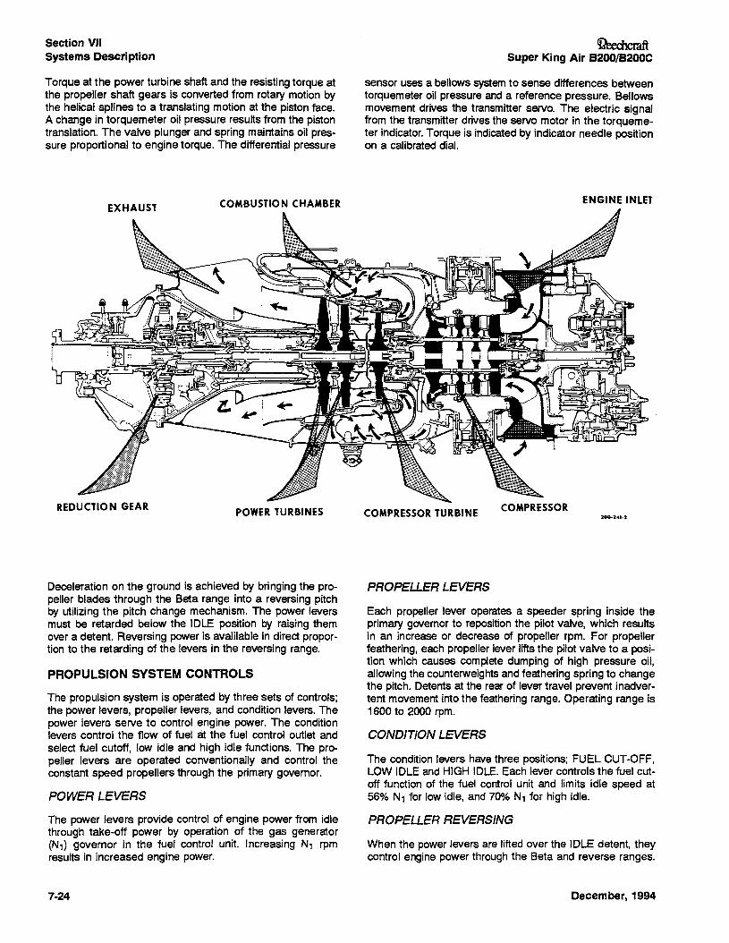
Section VIISystems Description
Torque at the power turbine shaft and the resisting torque atthe propeller shaft gears is converted from rotary motion bythe helical splines to a translating motion at the piston face.A change in torquemeter oil pressure results from the pistontranslation. The valve plunger and spring maintains oil pressure proportional to engine torque. The differential pressure
OeecbcraftSuper King Air B200/B200C
sensor uses a bellows system to sense differences betweentorquemeter oil pressure and a reference pressure. Bellowsmovement drives the transmitter servo. The electric signalfrom the transmitter drives the servo motor in the torquemeter indicator. Torque is indicated by indicator needle positionon a calibrated dial.
REDUCTION GEAR
COMBUSTION CHAMBER
POWER TURBINES COMPRESSOR TURBINE COMPRESSOR
ENGINE INLET
200-241-2
Deceleration on the ground is achieved by bringing the propeller blades through the Beta range into a reversing pitchby utilizing the pitch change mechanism. The power leversmust be retarded below the IDLE position by raising themover a detent. Reversing power is avaJilable in direct proportion to the retarding of the levers in the reversing range.
PROPULSION SYSTEM CONTROLS
The propulsion system is operated by three sets of controls;the power levers, propeller levers, and condition levers. Thepower levers serve to control engine power. The conditionlevers control the flow of fuel at the fuel control outlet andselect fuel cutoff, low idle and high idle functions. The propeller levers are operated conventionally and control theconstant speed propellers through the primary governor.
POWER LEVERS
The power levers provide control of engine power from idlethrough take-off power by operation of the gas generator(N1) governor in the fuel control unit. Increasing N1 rpmresults in increased engine power.
7-24
PROPELLER LEVERS
Each propeller lever operates a speeder spring inside theprimary governor to reposition the pilot valve, which resultsin an increase or decrease of propeller rpm. For propellerfeathering, each propeller lever lifts the pilot valve to a position which causes complete dumping of high pressure oil,allowing the counterweights and feathering spring to changethe pitch. Detents at the rear of lever travel prevent inadvertent movement into the feathering range. Operating range is1600 to 2000 rpm.
CONDITION LEVERS
The condition levers have three positions; FUEL CUT-OFF,LOW IDLE and HIGH IDLE. Each lever controls the fuel cutoff function of the fuel control unit and limits idle speed at56% N1 for low idle, and 70% N1 for high idle.
PROPELLER REVERSING
When the power levers are lifted over the IDLE detent, theycontrol engine power through the Beta and reverse ranges.
December, 1994
OeechcmftSuper King Air B200/B20OC
Propeller reversing on unimproved surfacesshould be accomplished carefully to preventpropeller erosion from reversed ahflow and,in dusty conditions, to prevent obscuring theoperator's vision.
Condition levers, when set at HIGH IDLE, keep the enginesoperating at 70% N1 high idle speedfor maximum reversingperformance.
Power levers should not be moved into thereversing position when the engines are notrunning because the reversing system will bedamaged.
FRICTION LOCKS
Four friction locks are located on the power quadrant of thepedestal. When they are rotated counterclockwise, the propUlsion system control levers can be moved freely. As thefriction locks are rotated clockwise, the control levers progressively become more resistant to movement, so that theywill not creep out of position.
ENGINE INSTRUMENTATION
Engine instruments, located to the left of the center portionof the instrument panel, are grouped according to their function. At the top, the ITT (Interstage Turbine Temperature)indicators and torquemeters are used to set take-off power.Climb and cruise power are established with the torquemetars and propeller tachometers while observing ITT limits.Gas generator (N1) operation is monitored by the gas generator tachometers. The lower grouping consists of the fuelflow indicators and the oil pressure/temperature indicators.
The ITT indicator gives an instantaneous reading of enginegas temperature between the compressor turbine and thepower turbines.
The torquemeters give an indication in foot-pounds of thetorque being applied to the propeller.
The propeller tachometer is read directly in revolutions perminute. The N1 or gas generator tachometer is read in percent of rpm, based on a figure of 37,500 rpm at 100%.Maximum continuous gas generator speed is limited to38,100 rpm or 104.5% N1.
Proper observation and interpretation of these instru~~nts
provide an indication of engine performance and condition.
A propeller synchroscope, located to the I~ft of ~he. oilpressure/temperature indicators, operates to gl~e an Indication of synchronization of the propellers. If the nght propeller
April, 1996
Section VIISystems Description
is operating at a higher rpm than the left, the face of thesynchroscope, a black and white cross pattern, spins in aclockwise rotation. Left, or counterclockwise, rotation indicates a higher rpm of the left propeller. This instrument aidsthe pilot in obtaining complete synchronization of propellers.
PROPELLER SYNCHROPHASER (OPTIONAL)
TYPE I SYSTEM
The Propeller Synchrophaser system automatically matchesthe RPM of the right propeller (slave propeller) to that of theleft propeller (master propeller) and maintains the blades ofone propeller at a predetermined relative position with theblades of the other propeller. To prevent the right propellerfrom losing excessive rpm if the left propeller is featheredwhile the synchrophaser is on, the synchrophaser hasa limited adjustment range from the manual governor setting.Normal govemor operation is unchanged but the synchrophaser will continuously monitor propeller rpm and resetthegovernor as required. A magnetic pickup mounted in eachpropeller overspeed governor and adjacent to each propeller deice brush block transmits electric pulses to a transistorized control box installed forward of the pedestal.
The control box converts any pulse rate cflfferences intocorrection commands, which are transmitted to a stepping typeactuator motor mounted on the right engine cowl forwardsupport ring. The motor then trims the right propellergovernor through a flexible shaft and trimmer assembly to exactlymatch the left propeller. The trimmer, installed between thegovernor control arm and the control cable, screws in or outto adjust the governor while leaving the control leversettingconstant. A toggte switch installed adjacent to the synchroscopeturns the system on. With the switch off, the aetLlatorautomatically runs to the center of its range of travel beforestopping to assure normal function when used again. Tooperate the system, synchronize the propellers in the normalmanner and turn the synchrophaser on. The system isdesigned for in-flight operations and is placarded to be offfor takeoff and landing. Therefore, with the system on andthe landinggear extended, the caution flashers and a yellowlight on the caution/advisory annunciator panel, PROPSYNCHON, will illuminate.
The right propeller rpm and phase will automatically beadjusted to correspond to the left. To change rpm, adjustboth propeller controls at the same time. This will keep theright govemor setting within the limiting rangeof the left propeller. If the synchrophaser is on but is unable to adjust theright propeller to match the left, the actuator has reached theend of its travel. To re-center, tum the switch off, synchronize the propellers manually, and turn the switch back on.
TYPE II SYSTEM
The Propeller Synchrophaser system is an electronic system certified for all operations including takeoff and landing.The system automatically matches the RPM of both propellers and positions them at a preset phase relationship inorder to reduce cabin noise.
Before engaging the system, manually set the RPM of eachengine to within 10 RPM of each other. When the prop sync
7-25
Section VIISystems Description
switch is turned on, engagement will automatically occurwhenthe relativephaseangle of the propellers is within 30°of the preset angle. When the system engages, both propeller speeds are increased by one-half the holding range ofthe system. To maintain synchronization. the systemincreases the RPM of the slower propeller and simultaneously reduces the RPM of the faster propeller. The system will never reduce RPM below that selected by the propeller control lever.
To change RPM with the system on, adjust both propellercontrols by the sameamount. If the synchrophaser is on butdoes not maintain synchronization, the system has reachedthe end of its range. Increasingthe setting of the slow propeller. or reducing the setting of the fast propeller, will bringthe speeds within the limited synchrophaser range. If preferred,the synchrophaser switch may be tumed off. the propellers re-synchronized manually. and the synchrophasertumed back on.
ENGINE LUBRICATION SYSTEM
Engine oil. contained in an integral tank betweenthe engineair intake and the accessory case, cools as well as lubricates the engine. An oil radiator located inside the lower
7·26
Oeed1craftSuper King Air B200/B200C
nacelle, keeps the engineoil temperature within the operating limits. A thermal element is used to regulate a bypassdoor which controls the volume of cooling air through theradiator. Engineoil also operatesthe propellerpitch changemechanism andthe engine torquemeter system.
The lubricationsystem capacity per engine is 3.5 U.S. gallons. The oil tank capacityis 2.3 gallonswith 5 quarts measured on the dipstick for adding purposes. Recommendedoils and oil changing procedures are listed in the SERVICING Section.
MAGNETIC CHIP DETECTOR
A magnetic chip detector is installed in the bottom of eachengine nose gearbox. This detector will activate a redannunciator, L CHIP DETECT or R CHIP.DETECT, to alertthe pilot of oil contamination indicating possible or pendingengine failure.
April, 1996
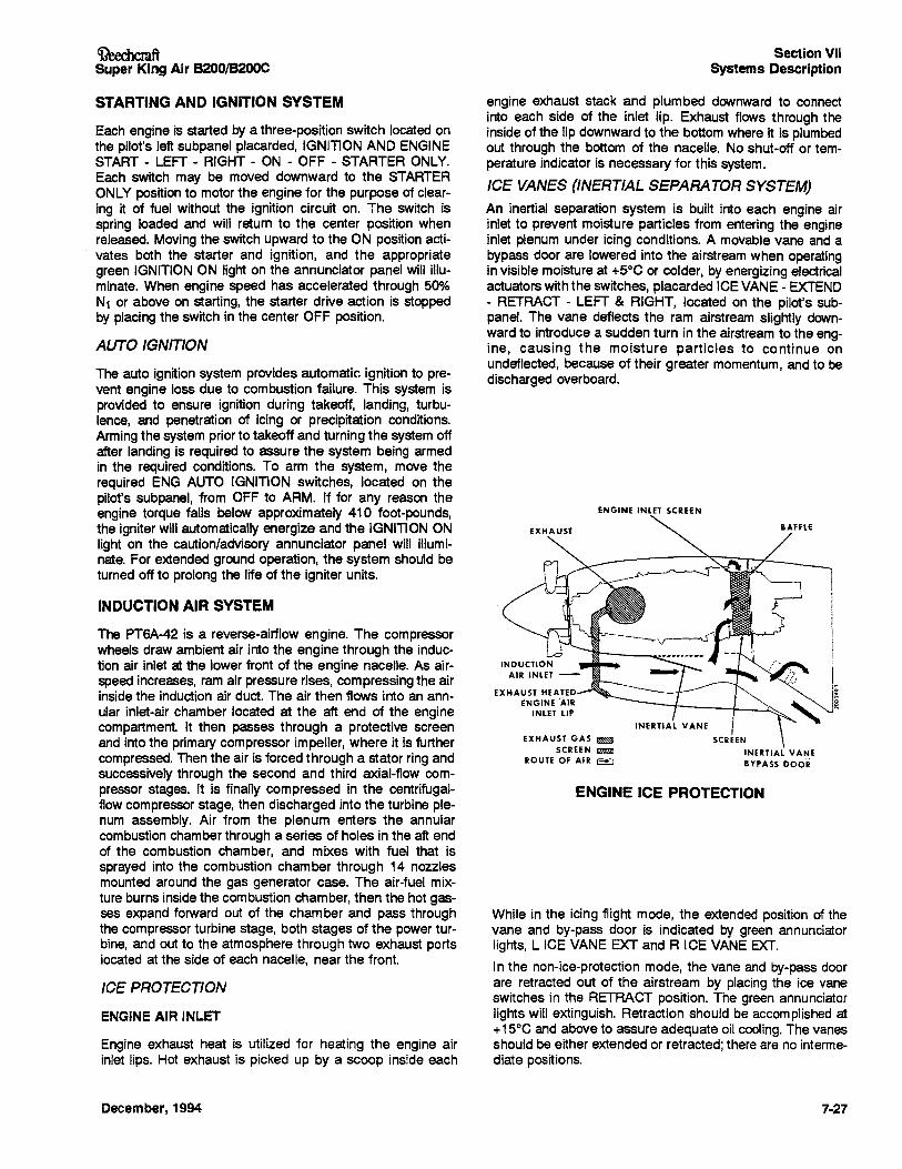
~ftSuper King Air B200/B200C
Section VIISystems Description
ENGINE ICE PROTECTION
While in the icing flight mode, the extended position of thevane and by-pass door is indicated by green annunciatorlights, L ICE VANE EXT and R ICE VANE EXT.
In the non-ice-protection mode, the vane and by-pass doorare retracted out of the airstream by placing the ice vaneswitches in the RETRACT position. The green annunciatorlights will extinguish. Retraction should be accomplished at+15°C and above to assure adequate oil cooling. The vanesshould be either extended or retracted; there are no intermediate positions.
engine exhaust stack and plumbed downward to connectinto each side of the inlet lip. Exhaust flows through theinside of the lip downward to the bottom where it is plumbedout through the bottom of the nacelle. No shut-off or temperature indicator is necessary for this system.
ICE VANES (INERTIAL SEPARATOR SYSTEM)
An inertial separation system is built into each engine airinlet to prevent moisture particles from entering the engineinlet plenum under icing conditions. A movable vane and abypass door are lowered into the airstream when operatingin visible moisture at +5°C or colder, by energizing electricalactuators with the switches, placarded ICE VANE - EXTEND- RETRACT - LEFT & RIGHT, located on the pilot's subpanel. The vane deflects the ram airstream slightly downward to introduce a sudden turn in the airstream to the engine, causing the moisture particles to continue onundeflected, because of their greater momentum, and to bedischarged overboard.
BAFFLE
=0ii!L.~
iINERTIAL VANE
SCREEN
INERTIAL VANEBYPASS ocos
ENGINE INLET SCREEN
EXHAUST
EXHAUST GAS ~SCREEN ~
ROUTE OF AIR ~
Engine exhaust heat is utilized for heating the engine airinlet lips. Hot exhaust is picked up by a scoop inside each
The auto ignition system provides automatic ignition to prevent engine loss due to combustion failure. This system isprovided to ensure ignition during takeoff, landing, turbulence, and penetration of icing or precipitation conditions.Arming the system prior to takeoff and turning the system offafter landing is required to assure the system being armedin the required conditions. To arm the system, move therequired ENG AUTO IGNITION switches, located on thepilot's suopanel, from OFF to ARM. If for any reason theengine torque falls below approximately 410 foot-pounds,the igniter will automatically energize and the IGNITION ONlight on the caution/advisory annunciator panel will illuminate. For extended ground operation, the system should beturned off to prolong the life of the igniter units.
ICE PROTECTION
ENGINEAIR INLET
INDUCTION AIR SYSTEM
STARTING AND IGNITION SYSTEM
The PT6A-42 is a reverse-airflow engine. The compressorwheels draw ambient air into the engine through the induction air inlet at the lower front of the engine nacelle. As airspeed increases, ram air pressure rises, compressing the airinside the induction air duct. The air then flows into an annular inlet-air chamber located at the aft end of the enginecompartment. It then passes through a protective screenand into the primary compressor impeller, where it is furthercompressed.Then the air is forced through a stator ring andsuccessively through the second and third axial-flow compressor stages. It is finally compressed in the centrifugalflow compressor stage, then discharged into the turbine plenum assembly. Air from the plenum enters the annularcombustion chamber through a series of holes in the aft endof the combustion chamber, and mixes with fuel that issprayed into the combustion chamber through 14 nozzlesmounted around the gas generator case. The air-fuel mixture burns inside the combustion chamber, then the hot gasses expand forward out of the chamber and pass throughthe compressor turbine stage, both stages of the power turbine, and out to the atmosphere through two exhaust portslocated at the side of each nacelle, near the front.
Each engine is started by a three-position switch located onthe pilot's left subpanel placarded, IGNITION AND ENGINESTART - LEFT - RIGHT - ON - OFF - STARTER ONLY.Each switch may be moved downward to the STARTERONLY position to motor the engine for the purpose of clearing it of fuel without the ignition circuit on. The switch isspring loaded and will return to the center position whenreleased. Moving the switch upward to the ON position activates both the starter and ignition, and the appropriategreen IGNITION ON light on the annunciator panel will illuminate. When engine speed has accelerated through 50%N1 or above on starting, the starter drive action is stoppedby placing the switch in the center OFF position.
AUTO IGNITION
December, 1994 7-27
Section VIISystems Description
If for any reason the vane does not attain the selected position within 15 seconds, a yellow L ICE VANE or RICEVANE light illuminates on the caution/advisory panel. In thisevent, a mechanical backup system is provided, and is actuated by pulling the T-handles just below the pilot's suopanelplacarded ICE VANE EMERGENCY - MANUAL EXTENSION - PULL - LEFT ENG - R ENG. Decrease airspeed to160 knots or less to reduce forces for manual extension.Normal airspeed may then be resumed.
Once the manual override system has beenengaged (i.e., anytime the manual ice vaneT-handle has been pulled out), do notattempt to retract or extend the ice vaneselectrically, even if the T-handle has beenpushed back in, until the override linkage inthe engine compartment has been properlyreset on the ground. (See the maintenancemanual for resetting procedure.)
When the vane is successfully positioned with the manualsystem, the yellow annunciator lights will extinguish. Thevane may also be retracted with the manual system. Duringmanual system use, the electric motor switch position mustmatch the manual handle position for a correct annunciatorreadout.
FUEL CONTROL
The engine fuel system consists of an engine-driven fuelpump, a fuel control unit (FeU), a flow divider and dumpvalve, dual fuel manifold, fourteen fuel nozzles, and two fuel
7-28
OeechcmftSuper King Air B200/B200C
drain valves. The fuel pump/fuel control unit assembly ismounted on the engine accessory case and is shaft-drivenat a speed proportional to that of the compressor turbine.The fuel pump delivers fuel to the FCU. Engine power output is established by power lever position. The power leveris linked to the governor in the FCU which regUlates fuelflow to the combustion section and thereby controls N1 andpower output. Increasing N1 rpm results in increased enginepower. System function depends upon the interaction of thefuel control unit governor and the propeller governor. Theposition of the fuel control unit metering valve is determinedby differential pressures that vary proportionately with powerrequired (as sensed by the fuel control unit) and propellerRPM.
The flow divider directs fuel from the metering valve to theprimary and secondary fuel manifolds (or primary manifoldonly, depending on engine power requirements) and thenceto the fuel nozzles. The flow divider also incorporates adump valve that automatically drains residual fuel from bothmanifolds at engine shutdown. The fuel drain valves drainfuel from the combustion chamber at engine shutdown andat engine false starts. A fuel purge system has beeninstalled in this case and on engine shutdown when fuelmanifold pressure subsides, allows the dump poppett valveto open, the purge tank pressure forces fuel out of the engine fuel manifold lines through the nozzles and into the combustion chamber where the fuel is consumed. Constant fuelpressure is maintained by a fuel filter bypass valve and apressure relief valve.
The oil-to-fueI heater mounted below the fuel pump on theaccessory case is a heat exchanger that transfers heat fromthe engine lubricating oil to preheat the fuel. A fueltemperature-sensing oil bypass valve regUlates the fuel tem..perature by either allOWing oil to flow through the heater circuit, or bypass it to the engine oil tank.
December, 1994
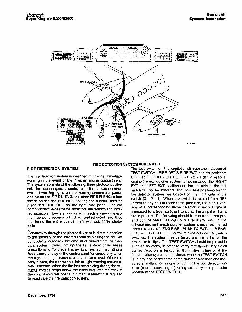
ConductiVitythrough the photocell varies in direct proportionto the intensity of the infrared radiation striking the cell. Asconductivity increases, the amount of current from the electrical system flowing through the flame detector increasesproportionally. To prevent stray light rays from signaling afalse alarm, a relay in the control amplifier closes only whenthe signal strength reaches a preset alarm level. When therelay closes, the appropriate left or right warning annunciators illuminate. When the fire has been extinguished, the celloutput voltage drops below the alarm level and the relay inthe control amplifier opens. No manual resetting is requiredto reactivate the fire detection system.
The fire detection system is designed to provide immediatewarning in the event of fire in either engine compartment.The system consists of the following: three photoconductivecells for each engine; a control amplifier for each engine;two red warning lights on the warning annunciator panel,one placarded FIRE L ENG, the other FIRE R ENG; a testswitch on the copilot's left subpanel; and a circuit breakerplacarded FIRE DET on the right side panel. The sixphotoconductive-cell flame detectors are sensitive to infrared radiation. They are positioned in each engine compartment so as to receive both direct and reflected rays, thusmonitoring the entire compartment with only three photocells.
~ftSuper" King Air B200/B200C
FIRE DETECTION SYSTEM
December, 1994
Section VIISystems Description'
:tOO-4S2-3
FIRE DETECTION SYSTEM SCHEMATICThe test switch on the copilot's left subpanet, placardedTEST SWITCH - FIRE DET·& FIRE EXT, has six positions:OFF - RIGHT EXT - LEFT EXT - 3 - 2 - 1 (If the optionalengine-fire-extinguisher system is not installed, the RIGHTEXT and LEFT EXT positions on the left side of the testswitch will not be installed.) the three test positions for thefire detector system are located on the right side of theswitch (3 - 2 - 1). When the switch is rotated from OFF(down) to anyone of these three positions, the output voltage of a corresponding flame detector in each engine isincreased to a level sufficient to signal the amplifier that afire is present. The following should illuminate: the red pilotand copilot MASTER WARNING flashers, and, if theoptional engine-fire-extinguisher system is installed, the redlenses placarded L ENG FIRE - PUSH TO EXT and R ENGIFIRE - PUSH TO EXT on the fire-extinguisher activationswitches. The system may be tested anytime, either on theground or in flight. The TEST SWITCH should be placed inall three positions, in order to verify that the circuitry for allsix fire detectors is functional. Illumination failure of all thefire detection system annunciators when the TEST SWITCH',is in anyone of the three flame-detector-test positions indicates a malfunction in one or both of the two detector circuits (one in each engine) being tested by that particularposition of the TEST SWITCH.
7-29-
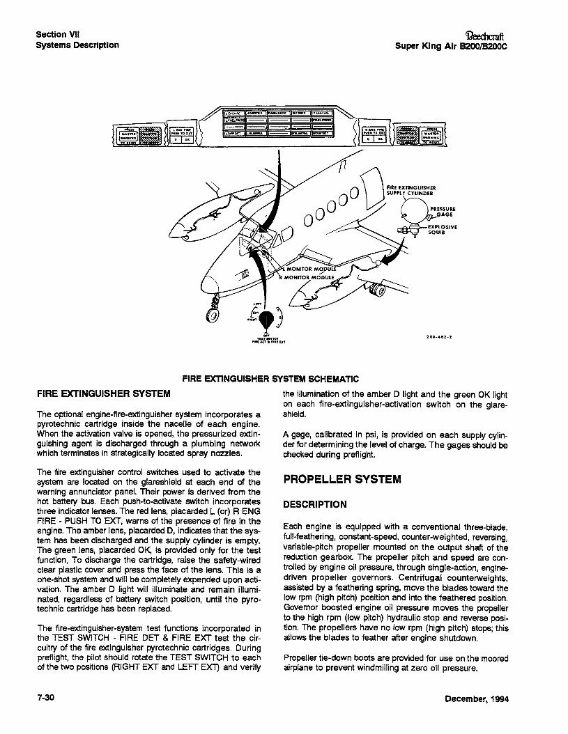
Section VIISystems Description
Ci?eechcmftSuper King Air B200/B200C
/\1""·" ,........~~~__---.,-\---,.o&.; L~un. - -- -- fIIIDS ,r---__-----,
Lc:..DE'T .....IL -- ....
The optional engine-fire-extinguisher system incorporates apyrotechnic cartridge inside the nacelle of each engine.When the activation valve is opened, the pressurized extinguishing agent is discharged through a plumbing networkwhich terminates in strategically located spray nozzles.
FIRE EXTINGUISHER SYSTEM
FIRE EXTINGUISHER SYSTEM SCHEMATIC
the illumination of the amber 0 light and the green OK lighton each fire-extinguisher-activation switch on the glareshield.
A gage, calibrated in psi, is provided on each supply cylinder for determining the level of charge. The gages should bechecked during preflight.
The fire extinguisher control switches used to activate thesystem are located on the glareshield at each end of thewarning annunciator panel. Their power is derived from thehot battery bus. Each push-to-activate switch incorporatesthree indicator lenses. The red lens, placarded L (or) R ENGFIRE - PUSH TO EXT, warns of the presence of fire in theengine. The amber lens, placarded 0, indicates that the system has been discharged and the supply cylinder is empty.The green lens, placarded OK, is provided only for the testfunction, To discharge the cartridge, raise the safety-wiredclear plastic cover and press the face of the lens. This is aone-shot system and will be completely expended upon activation. The amber D light will illuminate and remain illuminated, regardless of battery switch position, until the pyrotechnic cartridge has been replaced.
The fire-extinguisher-system test functions incorporated inthe TEST SWITCH - FIRE OET & FIRE EXT test the circuitry of the fire extingUisher pyrotechnic cartridges. Duringpreflight, the pilot should rotate the TEST SWITCH to eachof the two positions (RIGHT EXT and LEFT EX11 and verify
7·30
PROPELLER SYSTEM
DESCRIPTION
Each engine is equipped with a conventional three-blade,full-feathering, constant-speed, counter-weighted, reversing,variable-pitch propeller mounted on the output shaft of thereduction gearbox. The propeller pitch and speed are controlled by engine oil pressure, through single-action, enginedriven propeller governors. Centrifugal counterweights,assisted by a feathering spring, move the blades toward thelow rpm (high pitch) position and into the feathered position.Governor boosted engine oil pressure moves the propellerto the high rpm (low pitch) hydraUlic stop and reverse position. The propellers have no low rpm (high pitch) stops; thisallows the blades to feather after engine shutdown.
Propeller tie-down boots are provided for use on the mooredairplane to prevent windmilling at zero oil pressure.
December, 1994
Ci?eechcraftSuper King Air B200/B200C
PRIMARY LOW PITCH STOP
Low pitch propeller position is determined by the primary lowpitch stop which is a mechanically actuated hydraUlic stop.Beta and reverse blade angles are controlled by the powerlevers in the Beta and reverse range.
PROPELLER GOVERNORS
Two governors, a constant speed governor and an overspeed governor, control the propeller rpm. The constantspeed governor, mounted on top of the gear reduction housing, controls the propeller through its entire range. The propeller control lever operates the propeller by means of thisgovernor. If the constant speed governor should malfunctionby requesting more than 2000 rpm, the overspeed governorcuts in at 2080 rpm and dumps oil from the propeller to keepthe rpm from exceeding approximately 2080 rpm. A solenoidactuated by the PROP GOV TEST switch located on thepilot's subpanel, is provided for resetting the overspeed governor to approximately 1830 to 1910 rpm for test purposes.
If the propeller sticks or moves too slowly during a transientcondition causing the propeller governor to act too slOWly toprevent an overspeed condition, the power turbine governor,contained within the constant speed governor housing, actsas a fuel topping governor. When the propeller reaches2120 rpm, the fuel topping governor limits the fuel flow to thegas generator, reducing N1 rpm, which in turn prevents thepropeller rpm from exceeding apprOXimately 2200 rpm. During operation in the reverse range, the fuel topping governoris reset to approximately 95% propeller rpm before the propeller reaches a negative pitch angle. This ensures that theengine power is limited to maintain a propeller rpm somewhat less than that of the constant speed governor setting.The constant speed governor therefore will always sense anunderspeed condition and direct oil pressure to the propellerservo piston to permit operation in Beta and reverse ranges.
AUTOFEATHER SYSTEM
The automatic feathering system provides a means ofimmediately dumping oil from the propeller servo to enablethe feathering spring and counterweights to start the feathering action of the blades in the event of an engine failure.Although the system is armed by a switch on the pilot's subpanel, placarded AUTOFEATHER - ARM - OFF - TEST, thecompletion of the arming phase occurs when both powerlevers are advanced above 90% N1 at which time both theright and left indicator lights on the caution/advisory annunciator panel indicate a fully armed system. The annunciatorpanel lights are green, placarded L AUTOFEATHER and RAUTOFEATHER. The system will remain inoperative aslong as either power lever is retarded below 90% N1 position. The system is designed for use only during takeoff andlanding and should be turned off when establishing cruiseclimb. During takeoff or landing, if torquemeter oil pressureon either engine drops below a prescribed setting, the oil isdumped from the servo, the feathering spring starts theblades toward feather, and the autofeather system on theother engine is disarmed. Disarming of the autofeather portion of the operative engine is further indicated when theannunciator indicator light for that engine extinguishes.
December, 1994
Section VIISystems Description
FUEL SYSTEM
The fuel system consists of two separate systems connected by a valve-controlled crossfeed line. The fuel systemfor each engine is further divided into a main and auxiliaryfuel system. The main system consists of a nacelle tank, twowing leading edge tanks, two box section bladder tanks, andan integral (wet cell) tank, all interconnected to flow into thenacelle tank by gravity. This system of tanks is filled fromthe filler located near the wing tip.
The auxiliary fuel system consists of a center section tankwith its own filler opening, and an automatic fuel transfersystem to transfer the fuel into the main fuel system.
When the auxiliary tanks are filled, they will be used first.During transfer of auxiliary fuel, which is automatically controlled, the nacelle tanks are maintained full. A swing checkvalve in the gravity feed line from the outboard wing prevents reverse fuel flow. Upon exhaustion of the auxiliaryfuel, normal gravity transfer of the main wing fuel into thenacelle tanks will begin.
An anti-siphon valve is installed in each filler port which prevents loss of fuel or collapse of a fuel cell bladder in theevent of improper securing or loss of the filler cap.
The two systems are vented through a recessed ram ventcoupled to a protruding heated ram vent on the underside ofthe wing adjacent to the nacelle. One vent is recessed toprevent icing and the protruding vent, added as a backup, isheated to prevent icing.
All fuel is filtered with a firewall-mounted 20-micron filter.These filters incorporate an internal bypass which opens topermit uninterrupted fuel supply to the engine in the event offilter icing or blockage. In addition, a screen strainer islocated at each tank outlet before the fuel reaches the boostand transfer pumps. The main engine driven fuel pump hasan integral strainer to protect the pump.
A "differential pressure" fuel purge system is provided and islocated in the aft compartment of each nacelle. The systempurges the fuel that is left in the fuel manifolds at engineshutdown by forcing the fuel into the nozzles so that it isconsumed in the combustion chamber.
FUEL PUMPS
The engine driven fuel pump (high pressure) is mounted onthe accessory case in conjunction with the fuel control unit.Failure of this pump results in an immediate flameout. Theprimary boost pump (low pressure) is also engine driven andis mounted on a drive pad on the aft accessory section ofthe engine. This pump operates when the gas generator(N1) is turning and provides sufficient fuel for start, takeoff,all flight conditions (except operation with hot aviation gasoline above 20,000 feet altitUde) and operation with crossfeed.
In the event of a primary boost pump failure, the respectivered FUEL PRESS light in the annunciator panel will illuminate. This light illuminates when pressure decreases below10 : 1 psi. The light will be extinguished by switching on thestandby fuel pump on that side, thus increasing pressureabove 11 ± 2 psi.
7·31

Section VIISystems Description
Engine operation with the fuel pressure lighton is limited to 10 hours between overhaul,or replacement, of the engine driven fuelpump.
When using aviation gasoline during climbs above 20,000feet, the first indication of insufficient fuel pressure will be anintermittent flicker of the FUEL PRESS lights. A wide fluctuation of the fuel flow indicator may also be noted. Theseconditions can be eliminated by turning on a standby pump.
An electrically driven standby boost pump (low pressure),located in the bottom of each nacelle tank, performs threefunctions; it is a backup pump for use in the event of a primary fuel boost pump failure, it is for use with hot aviationgasoline above 20,000 feet, and it is used during crossfeedoperations. In the event of an inoperative standby pump,crossfeed can only be accomplished from the side of theoperative pump.
SERIALS 88-734, 88-793, 88-829, 88-854 thru88-870, 88-874 tnru 88-891, 88-894, 88-896 thruB8-911, BB-913 thru 88-1095, and 88-1097; BL-37thru BL-57:
Electrical power to operate the standby boost pumps is controlled by lever lock toggle switches, placarded STANDBYPUMP - ON - OFF, located on the fuel control panel and issupplied power from two independent sources. One sourceof power for either the right or the left standby pump is provided through the number 3 or number 4 feeder bus and isprotected by a 1O-ampere circuit breaker located on the fuelcontrol panel. This power is only available when the masterswitch is turned on. Another source of power comes directlyfrom the battery through the hot battery bus and is protectedby dual 5-ampere fuses located in the right Wing center section. The fuse panel may be serviced through an accessdoor on the bottom side of the wing outboard of the battery.This power source makes power available for the pumps atall times, regardless of the battery master switch position.These circuits are protected by diodes to prevent the failureof one circuit from disabling the other circuit. During shutdown, make certain both standby pump switches are off toprevent battery discharge.
SERIALS B8-1096, 88-1098 and After; BL-58 andAfter:
Electrical power to operate the standby boost pumps is controlled by lever lock toggle switches, placarded STANDBYPUMP - ON - OFF, located on the fuel control panel. It is
7-32
~ftSuper King Air B200/B200C
supplied power from the number 3 or number 4 feeder busand is protected by a 10-ampere circuit breaker located o~the fuel control panel. This power is only available when themaster switch is turned on. These circuits are protected bydiodes to prevent the failure of one circuit from disabling theother circuit.
AUXILIARY FUEL TRANSFER SYSTEM
The auxiliary tank fuel transfer system automatically transfers the fuel from the auxiliary tank to the nacelle tank without pilot action. Motive flow to a jet pump mounted in theaUXiliary tank sump is obtained from the engine fuel plumbing system downstream from the engine driven boost pumpand and routed through the transfer control motive flowvalve. The motive flow valve is energized to the open position by the control system to transfer aUXiliary fuel to thenacelle tank to be consumed by the engine during the initialportion of the flight. When an engine is started, pressure atthe engine driven boost pump closes a pressure switchWhich, after a 30 to 50 second time delay to avoid depletionof fuel pressure during starting, energizes the motive flowvalve. When the aUXiliary fuel is depleted, a low level floatswitch de-energizes the motive flow valve after a 30 to 60second time delay provided to prevent cycling of the motiveflow valve due to sloshing fuel.
In the event of a failure of the motive flow valve or the associated control circuitry, the loss of motive flow pressurewhen there is still fuel remaining in the auxiliary fuel tank issensed by a pressure switch and float switch, respectively,which illuminates a light placarded NO TRANSFER on thefuel control panel. During engine start, the pilot should notethat the NO TRANSFER lights extinguish 30 to 50 secondsafter engine start. A manual override is incorporated as abackup for the automatic transfer system. This is initiated byplacing the AUX TRANSFER switch, located in the fuel control panel to the OVERRIDE position.
USE OF AVIATION GASOLINE
If aviation gasoline must be used as an emergency fuel, itwill be necessary to determine how many hours the airplaneis operated on gasoline. Since the gasoline is being mixedwith the regular fuel, it is expedient to record the number ofgallons of gasoline taken aboard for each engine. Each engine is permitted 150 hours of operation on aviation gasolinebetween overhauls. This means that if one engine has anaverage fuel consumption of 50 gallons per hour, forexample, it is allowed 7500 gallons of aviation gasolinebetween overhauls. (Two engines; 15,000 gallons betweenoverhauls.)
December, 1994
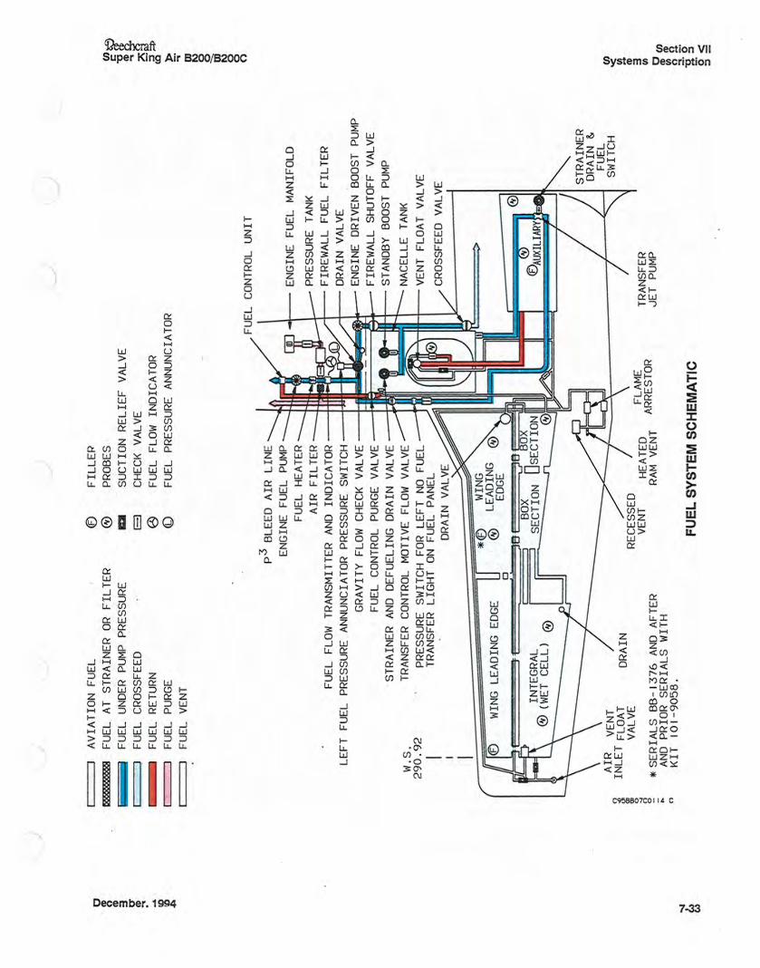
0(
JAV
IAT
ION
FUEL
®FI
LL
EP
P:Cc
cccc
CCCc
b4FU
ELAT
STR
AIN
EROR
FIL
TER
®PR
OBES
et>!
,FU
ELUN
DER
PUM
PPR
ESS
URE
aSU
CTI
ON
REL
IEF
VALV
E3 tT
FUEL
CRO
SSFE
EDet>
II
EJ
CHEC
KVA
LVE
:"'
@....
1MH
'FU
ELRE
TUR
NFU
ELFL
OWIN
DIC
ATOR
to<D
\0I
IFU
ELPU
RGE
FUEL
PRE
SSUR
EAN
NUN
CIA
TOR
~
II
FUEL
VEN
T~ o .Q OJ ~ o o ~ (l) 3 (J) 0
00(l)
ro
(J)o
0...
..,
_.-
'0
"S:s
o'<
:::J
=If :S::t
>(Q » :;.
®
TRAN
SFER
JET
PUM
PFL
AME
ARRE
STO
RHE
ATED
RAM
VEN
T
FU
EL
SY
ST
EM
SC
HE
MA
TIC
p3
BLEE
DA
IRL
INE
ENG
INE
FUEL
PUM
PFU
ELHE
ATER
ENG
INE
FUEL
MAN
IFOL
DA
IRFI
LT
ERPR
ESS
URE
TANK
F UEL
FLOW
TRAN
SMIT
TER
AND
IND
ICAT
ORF
IRE
WALL
FUEL
FIL
TER
LEF
TFU
ELPR
ESS
URE
ANNU
NC
IATO
RPR
ESS
URE
SWIT
CHDR
AIN
VALV
EGR
AVIT
YFL
OWCH
ECK
VALV
EEN
GIN
ED
RIV
ENBO
OST
PUM
PFU
ELCO
NTRO
LPU
RGE
VALV
EF
IRE
WALL
SHUT
OFF
VALV
EST
RA
INER
AND
DEFU
ELIN
GDR
AIN
VALV
EST
ANDB
YBO
OST
PUM
PTR
ANSF
ERCO
NTRO
LMO
TIV
EFL
OWVA
LVE
NACE
LLE
TANK
PRES
SUR
ESW
ITCH
FOR
LEF
TNO
FUEL
VEN
TFL
OAT
VALV
ETR
ANSF
ERLI
GH
TO
NFU
ELPA
NEL
DRA
INVA
LVE
/CRO
SSFE
EDVA
LVE
*SE
RIA
LS
BB-
1376
AND
AFTE
RAN
DPR
IOR
SER
IALS
WIT
HK
IT10
1-9
058
.
\~.
S.
290
.92
I I I
o m o 8 f>o o
~
Section VII .Systems Description
CROSSFEED
During emergency single-engine operation, it may becomenecessary to supply fuel to the operative engine from thefuel system on the opposite side. The simplified crossfeedsystem is placarded for fuel selection with a diagram on theupper fuel control panel. Place the standby fuel pumpswitches in the OFF position when crossfeeding. A leverlock switch, placarded CROSSFEED FLOW, is moved fromthe center OFF position to the left or to the right, dependingon direction of fuel flow. This opens the crossfeed valve,energizing the standby pump on the side from which crossfeed is desired, and de-energizes the motive flow valve inthe fuel system on the side being fed. When the crossfeedmode is energized, a green FUEL CROSSFEED light on thecaution/advisory panel will illuminate.
FIREWALL SHUTOFF
The system incorporates two firewall shutoff valves controlled by two switches, one on each side of the fuel systemcircuit breaker panel, located on the fuel control panel.These switches, respectively LEFT and RIGHT, are placarded FIREWALL SHUTOFF VALVE - OPEN - CLOSED. Ared guard over each switch is an aid in preventing inadvertent operation. The fi rewall shutoff valves receive electricalpower from the main buses and also from the hot batterybus which is connected directly to the battery.
FUEL ROUTING IN ENGINE COMPARTMENT
Just forward of the firewall shutoff valve is the primary engine driven boost pump. From the primary boost pump, thefuel is routed to the main fuel filter, the fuel flow indicatortransmitter, through a fuel heater that utilizes heat from theengine oil to warm the fuel, through the engine driven fuelpump, then to the fuel control unit. From there it is directedthrough the dual fuel manifold to the fuel outlet nozzles andinto the annular combustion chamber. Fuel is also takenfrom just downstream of the main fuel filter to' supply the jettransfer pump motive flow.
CUeechcraftSuper King Air 8200/8200C
FUEL PURGE SYSTEM
Engine compressor discharge air (P3 air) pressurizes asmall purge tank. During engine shutdown, fuel manifoldpressure subsides, thus allowing the engine fuel manifoldpoppett valve to open. The purge tank pressure forces fuelout of the engine fuel manifold lines) through the nozzles,and into the com bustion chamber. As the fuel is burned, amomentary surge in (N1) gas generator rpm should beobserved. The entire operation is automatic and requires noinput from the crew.
During engine starting, fuel manifold pressure closes thefuel manifold poppett valve, allowing P3 air to pressurize thepurge tank.
FUEL GAGING SYSTEM
The airplane is equipped with a capacitance type fuel quantity indication system. A maximum indication error of 3% fullscale may be encountered in the system. The system isdesigned for the use of Jet A, Jet A1, JP-5 and JP-8 aviation kerosene) and compensates for changes in fuel densitydue to temperature changes. If other fuels are used, thesystem will not indicate correctly. See OTHER NORMALPROCEDURES in Section IV for instructions when using JetB, JP-4, or aviation gasoline.
The LEFT fuel quantity indicator on the fuel control panelindicates the amount of fuel remaining in the left-side mainfuel system tanks when the fuel QUANTITY SELECT switchin the MAIN (upper) position, and the amount of fuel remaining in the left-side auxiliary fuel tank when the fuel QUANTITY SELECT switch is in the AUXILIARY (lower) position.The RIGH1- fuel quantity indicator indicates the sameinformation for the right-side fuel systems, depending upon theposition of the FUEL QUANTITY switch. The gages aremarked in pounds.
ELECTRICAL SYSTEM
FUEL DRAINS
During each preflight, the fuel sumps on the tanks, pumpsand filters should be bled to check for fuel contamination.There are five sump drains and one filter drain in each Wing.They are located as follows:
DRAINS
Leading Edge Tank
Integral Tank
Firewall Fuel Filter
Sump Strainer
Gravity Feed Line
Auxiliary Tank
7-34
LOCATION
Outboard of nacelle underside of wing
Underside of wing forwardof aileron
Underside of cowling forward 'of firewall
Bottom center of nacelleforward of wheel well
Aft of wheel well
At wing root just forward ofthe flap
The airplane electrical system is a 28-VDC (nominal) systemwith the negative lead of each power source grounded to themain airplane structure. DC electrical power is provided byone 34-ampere-hour, air cooled, 20-cell, nickel-cadmiumbattery, and two 250-am pere starter/generators connectedin parallel. The system is capable of supplying power to allsubsystems that are necessary for normal operation of theairplane. A hot battery bus is provided for emergency operation of certain essential equipment and the cabin entrythreshold light circuit. Power to the main bus from the battery is routed through the battery relay which is controlled bya switch placarded BAT - ON - OFF, located on the pilot'ssubpanel. Power to the bus system from the generators isrouted through reverse-current-protection circuitry. Reversecurrent protection prevents the generators from absorbingpower from the bus when the generator voltage is less thanthe bus voltage. The generators are controlled by switches,placarded GEN 1 and GEN 2, located on the pilot's subpanel.
December, 1994
CDeechcmftSuper King Air B200/B200C
NOTEIn order to turn the generator ON, the generator control switch must first be heldupward in the spring-loaded RESET positionfor a minimum of one second, then releasedto the ON position.
Starter power to each individual starter/generator is provided !rom the main bus through a starter relay. The startcycle IS controlled by a three-position switch for each engine, placarded IGNITION AND ENGINE START - ON - OFF- STARTER ONLY, on the pilot's subpanel. The starter/generator drives the compressor section of the enginethrough the accessory gearing. The starter/generator initiallydraws approximately 1100 amperes, then drops rapidly toabout 300 amperes as the engine reaches 20% N1.
Power is supplied from three sources: the battery, the rightgenerator, and the left generator. The generator buses areinterconnected by two 325-ampere current limiters. Thee~ire bus system operates as a single bus, with powerbeing supplied by the battery and both generators. Thereare four dual-fed sub-buses. Each sub-bus is supplied~o~er from either ~enerator main bus through a SO-amplimiter, a 70-amp diode, and a 50-amp circuit breaker. Allelectrical loads are divided among these buses except asnoted on the accompanying Power Distribution Schematic.The equipment on the buses is arranged so that all itemswith duplicate functions (such as right and left landing lights)are connected to diffe~ent buses. Among the loads on thegenerator buses are the number 1 and number 2 inverters.Through relay circuitry, the INVERTER selector switch activates the selected inverter, which provides 400-hertz, 115volt, alternating current to the avionics equipment,and 400hertz, 26 VAC to the torquemeters. The volt/frequency meterindicates the voltage and frequency of the alternating current being supplied to the avionics equipment.
The ge~erator:s a~e controlled by individual voltage regulators which maintain a constant voltage during variations inengine speed and electrical load requirements. The generators are connected to the voltage regulating circuits bymeans of control switches located on the pilot's left subpanel. The voltage regulating circuit will automatically disable or enable a generator's output to the bus. The load oneach generator is indicated by the respective left and rightvolt/loadmeter located in the overhead panel.
qverheating of the nickel-cadmium battery will cause thebattery charge current to increase. Therefore, a yellow BATTERY CHARGE caution annunciator light is provlded in thecaution/adVisory annunciator panel to alert the pilot of the
December, 1994
Section VIISystems Description
possibility of battery overheating. A Battery Charge CurrentDetector will cause illumination of the yellow BAlTERY~HARGE annunciator whenever the battery charge currentIS above 7 amps. Thus, the BATIERY CHARGE annunciator may occasionally illuminate for short intervals whenheavy loads switch off. Following a battery-powered enginestart, the battery recharge current is very high and causesillumination of the BATTERY CHARGE annunciator thusproviding an automatic self-test of the detector and th'e battery. As the battery approaches a full charge and the chargecurrent decreases below 7 amps, the annunciator will extinguish. This will normally occur within a few minutes after anengine start, but may require a longer time if the battery hasa low state of charge, low charge voltage per cell (20-cellbat~ery), or low. battery temperature. This system isdeSigned for continuous monitoring of the battery condition.
lllu~ination of.the BATTE~,!, CHARGE annunciator in flightcautions the pilot that conditions may exist that may eventually damage the battery. The operator should check the battery ch~rge current with the loadmeter. This is accomplishedby turning off one generator and noting the load on theremaining generator. Turn off the battery and note the loadmeter change. If the change is greater than .025, the batterysho~ld be left off the ~us and should be inspeded afterlan.dlng: If the annunciator remains on after the batteryswitch IS moved to the OFF position, a malfunction is indicated in either the battery system or charge current detector, in which case the airplane should be landed as soon aspracticable. The battery switch should be turned ON forlanding in order to avoid electrical transients caused bypower fluctuations.
EXTERNAL POWER
For ground operation, an external power socket locatedunder the right wing outboard of the nacelle, is pr~vided forconnecting an,auxiliary power unit. A relay in the externalpower circuit will close only of the external source polarity iscorrect. The battery switch must be on before the externalpower relay will close and allow external power to enter theairplane electrical system. The battery will also tend toabsorb voltag~ transi~nts when operating avionics equipment and dUring engine starts. Otherwise, the transientsmight damage the many solid state components in the airplane.
) For starting, an external power source capable of supplyingup to 1000 amperes (300 amperes maximum continuous)should .be used. A caution light on the caution/advisoryannunciator panel, EXT PWR, is provided to alert the operator when an external DC power plug is connected to the airplane.
7·35
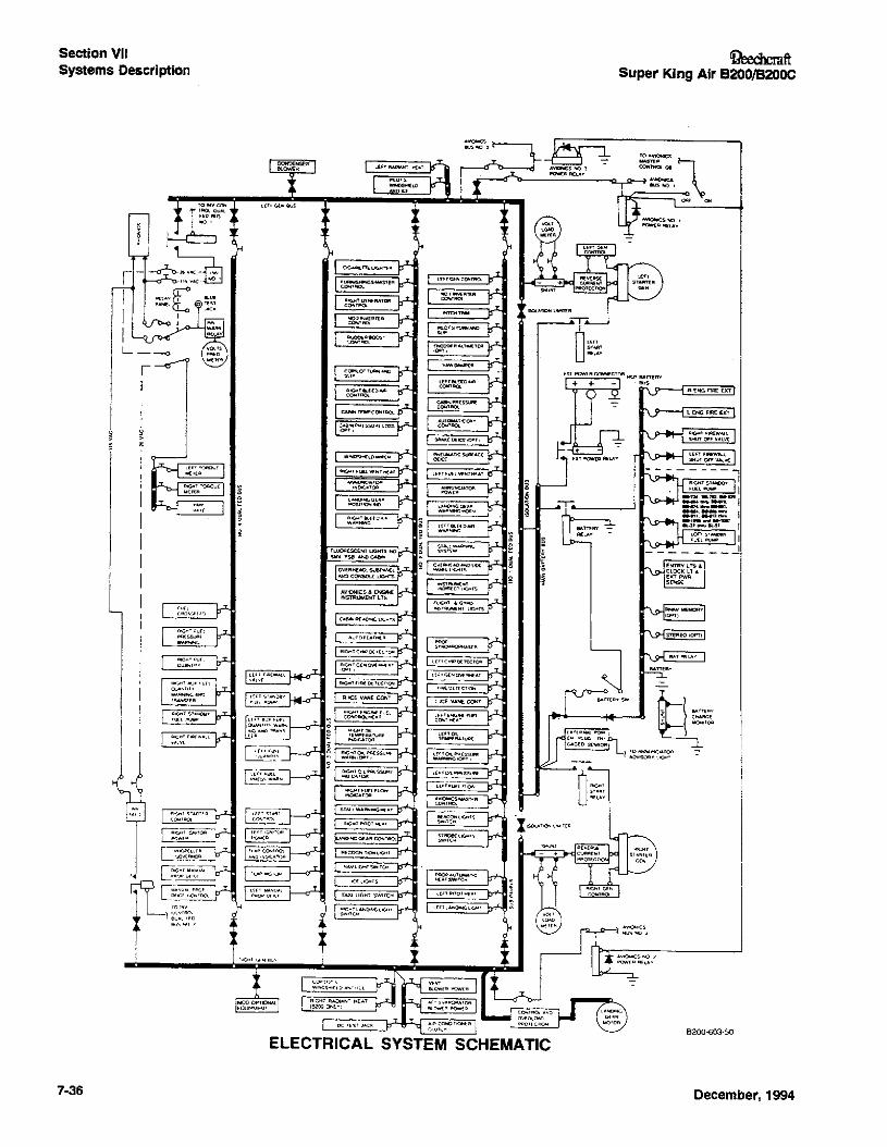
Section VIISystems Description
IIII
7-36
ELECTRICAL SYSTEM SCHEMATIC
Ci?eechcmftSuper King Air B200/B200C
3. ~IT()A
1:gv~~~:~:~R
8200-603-50
December, 1994
'ReechcmftSuper King Air B200/B200C
LIGHTING SYSTEMS
COCKPIT
An overhead light control panel, easily accessible to bothpilot and copilot, incorporates a functional arrangement of alllighting systems in the cockpit. Each light group has its ownrheostat switch placarded BRT - OFF. The MASTER PANELLIGHTS - ON - OFF switch controls the overhead light control panel lights,fuel control panel lights, engine instrumentlights, radio panel lights, subpanel and console lights, pilotand copilot instrument lights, and gyro instrument lights. Theinstrument indirect lights in the glareshield and overheadmap lights are individually controlled by separate rheostatswitches.
The push-button FREE AIR TEMP switch, located on the leftsidewall panel next to the gage, turns ON and OFF the lightsnear the outside air temperature gage.
CABIN
A three-position switch on the copilot's subpanel, placardedCABIN LIGHTS - START BRIGHT - DIM - OFF, controls thefluorescent cabin lights. The switch to the right of the interiorlight switch activates the cabin NO SMOKING/FASTENSEAT BELT signs and accompanying chimes. This threeposition switch is placarded CABIN LIGHTS - NO SMOKE &FSB - FSB - OFF.
The baggage-area light is controlled by a two-position switchjust inside the airstair door aft of the door frame and is connected to the hot battery bus.
A threshold light is located forward of the airstair door atfloor level, and an aisle light is located at floor level aft of thespar cover. A switch adjacent to the threshold light turnsboth these lights on and off. The switch also turns the exterior entry light on and off. When the airstair door is closed,all the lights controlled by the threshold light switch willextinguish.
When the master switch is on, the individual reading lightsalong the top of the cabin may be turned on or off by thepassengers with a push-button switch adjacent to each light.
EXTERIOR
Switches for the landing lights, taxi lights, wing ice lights,navigation lights, recognition lights, rotating beacons, andwing-tip and tail strobe lights are located on the pilot's subpanel. They are appropriately placarded as to their function.
Tail floodlights, if installed, are incorporated into the horizontal stabilizers and are designed to illuminate both sides of
December, 1994
Section VIISystems Description
the vertical stabilizer. A switch for these lights, placardedLIGHTS - TAIL FLOOD - OFF, is located on the pilot's subpanel.
A flush-mounted floodlight forward of the flaps in the bottomof the left wing may be installed. This entry light providesillumination of the area around the airstair door, to providepassenger convenience at night. It is controlled by thethreshold light switch just inside the door on the forwarddoor frame, and will extingUish automatically whenever thecabin door is closed.
ENVIRONMENTAL SYSTEM
The environmental system consists of the bleed air pressurization, heating and cooling systems, and their associatedcontrols.
PRESSURIZATION SYSTEM
The pressurization system is designed to provide a normalworking pressure differential of 6.5 ::t .1 psi, which will provide cabin pressure altitudes of approximately; 2800 feet atan airplane altitude of 20,000 feet, 8600 feet at 31,000 feet,and 10,400 feet at 35,000 feet.
Bleed air from the compressor section of each engine is utilized to pressurize the pressure vessel. A flow control unit inthe nacelle of each engine controls the pressure of the bleedair and mixes ambient air with it, in order to provide an airmixture suitable for the pressurization function. The mixtureflows to the environmental bleed air shutoff valve, which iscontrolled by a switch placarded BLEED AIR VALVE - LEFT(or) RIGHT - OPEN - ENVIR OFF - INSTR &ENVIR OFF inthe ENVIRONMENTAL controls group on the copilot's subpanel. When this switch is in either the ENVIR(onmental air)OFF or the INSTR(ument air) & ENVIR(onmental air) OFFposition, the valve is closed. When it is in the OPEN position, the air mixture flows through the valve and to the air-toair heat exchanger. Depending upon the position of thebypass valves, a greater or lesser volume of the air mixturewill be routed through or around the heat exchanger. Thetemperature of the air flowing through the heat exchanger islowered as heat is transferred to cooling fins, which are inturn cooled by ram airflow through the fins of the heatexchanger. The air leaying both (left and right) bypassvalves, is then ducted into a single muffler, located underthe right floorboard forward of the main spar, which helpsensure quiet operation of the environmental bleed air system. The air mixture is then ducted from the muffler into themixing plenum, located under the copilot's floorboard.
7·37
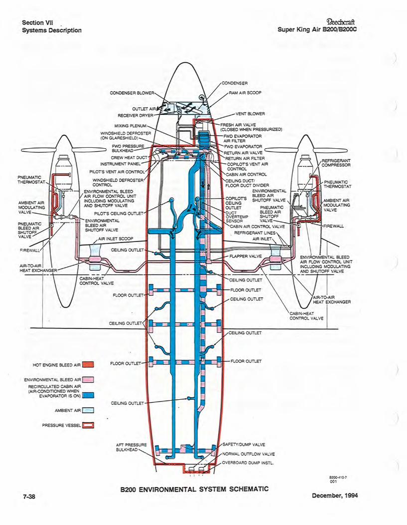
Section VIISystems Description
PNEUMATICTHERMOSTAT
PNEUMA~IC ••- ••BLEED AIRSHUTOFFVALVE
FIREWALL I \AIR·To-AIRHEAT EXCHANGER
HOT ENGINE BLEED AIR
ENVIRONMENTAL BLEED AIRGdRECIRCULATED CABIN AIR(AIR-CO DITIONED WHEN
EVAPORATOR IS 0 )
AMBIENT AIR~
PRESSURE VESSEL
7-38
~ftSuper King Air 8200/8200C
FRESH AIR VALVE(CLOSED WHEN PRESSURIZED)
l'ZZZII~~-FWD EVAPORATOR
~1~~~~~I~~I~~~AIR FILTERFWD PRESSURE FWD EVAPORATOR _----~BULKHEAD RETURN AIR VALVE -----...;
CREW HEAT DUCT RETURN AIR FILTER
INSTRUMENT PANEL COPILors VENT AIRCONTROL
CABIN AIR CONTROL
CEILING DUCTIFLOOR DUCT DIVIDER
ENVIRONMENTALBLEED AIRSHUTOFF VALVE
P EUMATICBLEED AIRSHUTOFF
SENSOR VALVE -.JlCF~~~CABIN AIR CO TROL VALVE
REFRIGERANT LINES
AIR INLET
FLOOR OUTLET
CElLI G OUTLET
OVERBOARD DUMP INSTL.
8200 ENVIRONMENTAL SYSTEM SCHEMATICDecember, 1994
)
J
/
/
OeechcraftSuper King Air B200/B200C
A partition divides the mixing plenum into two sections. Onesection supplies the floor-outlet duet, and the other suppliesthe ceiling-outlet duct. Both sections receive recirculatedcabin air from the forward vent blower. This air passesthrough the forward evaporator, so it will be cooled if the airconditioner is operating. Even in the event that the forwardvent blower becomes inoperative, some air will still be circulated, due to a special nozzle in the discharge side of themixing plenum.
The environmental bleed air duct is routed into the floor-ductsection of the mixing plenum, then curves back to dischargethe environmental bleed air toward the aft end of the floorduct section of the mixing plenum. Forward of the dischargeend of the environmental bleed air duct, warm air is tappedoffand ducted up through the top of the mixing plenum andinto the crew heat duct, which also receives recirculatedcabin air from the mixing plenum. A valve on the forwardside of the crew heat duet allows air to be tapped off fordelivery to the windshield defroster when the DEFROSTAIRknob on the pilot's left suopanel is pulled out. Eyeball outletsat the left and right sides of the glareshieldare also suppliedair from the defrost air tap.
The air from the environmental bleed air duct is mixed withrecirculated cabin air (which mayor may not be air conditioned) in the mixing plenum, then routed into the floor-outletduct. This pressurized air is then introduced into the cabinthrough the floor registers. Finally, the air flows out of thepressure vessel through the outflow valve, located on the aftpressure bulkhead. A silencer on the outflow and safety/dump valves ensures quiet operation.
The mixture from both flow control units is delivered to thepressure vessel at a rate which can vary from about 8 to 16pounds per minute, depending upon ambient temperatureand pressure altitude. Pressure within the cabin and the rateof cabin-pressure changes are regulated by pneumaticmodulation of the outflow valve, which controls the rate atwhich air can escape from the pressure vessel.
A vacuum-operated safety valve is mounted adjacent to theoutflow valve on the aft pressure bulkhead. It is designed toserve three functions: to provide pressure relief in the eventof malfunction of the normal outflow valve; to allow depressurization of the pressure vessel whenever the cabin pressure switch is moved into the DUMP position; and to keepthe pressure vessel unpressurized while the airplane is onthe ground with the left landing-gear safety switch compressed. A negative-pressure relief function is also incorporated into both the outflow and the safety valves. This prevents outside atmospheric pressure's exceeding cabinpressure by more than 0.1 psi during rapid descents, even ifbleed air inflow ceases.
On airplanes B8-1284 and after, both the outflow valve andthe safety valve are vented overboard, to preclude moisturebuild-up in the aft fuselage.
When the BLEEDAIR VALVE switches on the copilot's subpanel are OPEN (up), the air mixture from the flow controlunits enters the pressure vessel. While the airplane is on theground, a left landing gear safety-switch-activated solenoidvalve in each flow control unit keeps the ambient-air intake
December, 1994
Section VIISystems Description
port closed, allOWing only bleed air to be delivered into thepressure vessel. At lift-off, the safety valve closes and theambient air shutoff solenoid valve in the left flow control unitopens; apprOXimately 6 seconds later, the solenoid in theright flow control unit opens. Consequently, by increasingthe volume of airflow into the pressure vessel in stages,excessive pressure bumps during takeoff are avoided.
An adjustable cabin pressurization controller is mounted inthe pedestal. It commands modulation of the outflow valve.A dual-scale indicator dial is mounted in the center of thepressurization controller. The outer scale (CABIN ALT) indicates the cabin pressure altitude which the pressurizationcontroller is set to maintain. The inner scale (ACFT AL1')indicates the maximum ambient pressure altitude at whichthe airplane can fly without causing the cabin pressure altitude to climb above the value selected on the outer scale(CABIN AL1) of the dial. The indicated value on each scaleis read opposite the index mark at the forward (top) positionI
of the dial. Both scales rotate together when the cabin altitude selector knob, placarded CABIN ALT, is turned. Themaximum cabin pressure altitude is selected by turning thecabin altitude selector knob until the desired setting on theCABIN ALT dial is aligned with the index mark. The maximum cabin altitude selected may be anywhere from -1000 to+15,000 feet MSL. The rate control selector knob is placarded RATE - MIN - MAX. The rate at which the cabin pressure altitude changes from the current value to the selectedvalue is controlled by rotating the rate control selector knob.The rate of change selected may be from apprOXimately50-300 to approximately 2000 ~500 feet per minute.
The actual cabin pressure altitude is continuously indicated"by the cabin altimeter, which is mounted in the right side ofthe panel that is located between the caution/advisoryannunciator panel and the pedestal. Immediately to the leftof the cabin altimeter is the cabin vertical speed (CABINCLIMB) indicator, which continuously indicates the rate atwhich the cabin pressure altitude is changing.
The cabin pressure switch, located forward of the pressurization controller on the pedestal, is placarded CABINPRESS - DUMP - PRESS - TEST. When this switch is in the,DUMP (forward) position, the safety valve is held open, sothat the-cabin will depressurize and/or remain unpressurized. When it is in the PRESS (center) position, the safetyvalve is normally closed in flight, and the outflow valve iscontrolled by the pressurization controller, so that the cabinwill pressurize. When the switch is held in the spring-loaded"TEST (aft) position, the safety valve is held closed, bypassing the landing-gear safety switch, to facilitate testing of thepressurization system on the ground.
Prior to takeoff, the cabin altitude selector knob should beadjusted so that the ACFT ALT scale on the indicator dialindicates an altitude approximately 1000 feet above theplanned cruise pressure altitude, and the CABIN ALT scaleindicates an altitude at least 500 feet above the takeoff field,pressure altitude. The rate control selector knob should beadjusted as desired; setting the index mark at the 12-o'clockposition will provide the most comfortable cabin rate otclimb. The cabin pressure switch should be checked'toensure that it is in the PRESS position. As the airplane
7-39,"
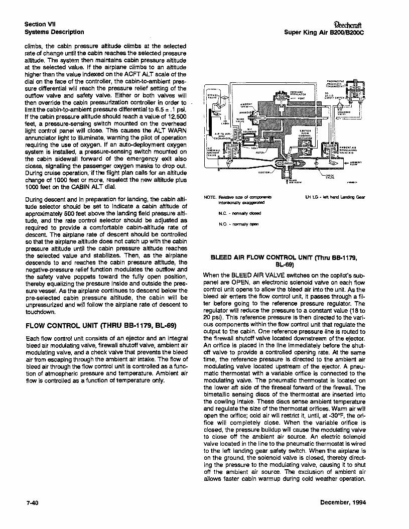
Section VIISystems Description
climbs, the cabin pressure altitude climbs at the selectedrate of change until the cabin reaches the selected pressurealtitude. The system then maintains cabin pressure altitudeat the selected value. If the airplane climbs to an altitude·higherthan the value indexed on the ACFT ALT scale of thedial on the face of the controller, the cabin-to-ambient pressure differential will reach the pressure relief setting of theoutflow valve and safety valve. Either or both valves willthen override the cabin pressurization controller in order tolimit the cacm-tc-ernelentpressure differential to 6.5 :!: .1 psi.If the cabin pressure altitude should reach a value of 12,500feet, a pressure-sensing switch mounted on the overheadlight control panel will close. This causes the ALT WARNannunciator light to illuminate, warning the pilot of operationrequiring the use of oxygen. If an auto-deployment oxygensystem is installed, a pressure-sensing switch mounted onthe cabin sidewall forward of the emergency exit alsocloses, signalling the passenger oxygen masks to drop out.During cruise operation,-if the flight plan calls for an altitudechange of 1000 feet or more, reselect the new altitude plus1000feet on the CABIN ALT dial.
OeechcmftSuper King Air B200/B200C
BLEED AIR FLOW CONTROL UNIT (Thru B8-1179,BL-69)
When the BLEED AIR VALVE switches on the copilot's subpanel are OPEN, an electronic solenoid valve on each flowcontrol unit opens to allow the bleed air into the unit. As thebleed air enters the flow control unit, it passes through a filter before going to the reference pressure regUlator. TheregUlator will reduce the pressure to a constant value (18 to20 psi). This reference pressure is then directed to the various components within the flow control unit that regulate theoutput to the cabin. One reference pressure line is routed tothe firewall shutoff valve located downstream of the ejector.An orifice is placed in the line immediately before the shutoff valve to provide a controlled opening rate. At the sametime, the reference pressure is directed to the ambient airmodulating valve located upstream of the ejector. A pneumatic thermostat with a variable orifice is connected to themodulating valve. The pneumatic thermostat is located onthe lower aft side of the fireseal forward of the firewall. Thebimetallic sensing discs of the thermostat are inserted intothe cowling intake. These discs sense ambient temperatureand regulate the size of the thermostat orifices. Warm air willopen the orifice; cold air will restrict it, until, at -30°F, the orifice will completely close. When the variable orifice isclosed, the pressure buildup will cause the modulating valveto close off the ambient air source. An electric solenoidvalve located in the line to the pneumatic thermostat is wiredto the left landing gear safety switch. When the airplane ison the ground, the solenoid valve is closed, thereby directing the pressure to the modulating valve, causing it to shutoff the ambient air source. The exciusion of ambient airallows faster cabin warmup during cold weather operation.
During descent and in preparation for landing, the cabin altitude selector should be set to indicate a cabin altitude ofapproximately 500 feet above the landing field pressure altitude, and the rate control selector should be adjusted asrequired to provide a comfortable cabin-altitude rate ofdescent. The airplane rate of descent should be controlledso that the airplane altitude does not catch up with the cabinpressure altitude until the cabin pressure altitude reachesthe selected value and stabilizes. Then, as the airplanedescends to and reaches the cabin pressure altitude, thenegative-pressure relief function modulates the outflow andthe safety valve poppets toward the fully open position,thereby equalizing the pressure inside and outside the pressure vessel. As the airplane continues to descend below thepre-selected cabin pressure altitude, the cabin will beunpressurized and will follow the airplane rate of descent totouchdown.
FLOW CONTROL UNIT (THRU 88-1179, BL-69)
Each flow control unit consists of an ejector and an integralbleed air modulating valve, firewall shutoff valve, ambient airmodulating valve, and a check valve that prevents the bleedair from escaping through the ambient air intake. The flow ofbleed air through the flow control unit is controlled as a function of atmospheric pressure and temperature. Ambient airflow is controlled as a function of temperature only.
NOTE: Relative size of componentsintentionally exaggerated
N.C. - nonnally ctosed
N.O. - nonnally open
LH LG - left hand landing Gear
7·40 December, 1994
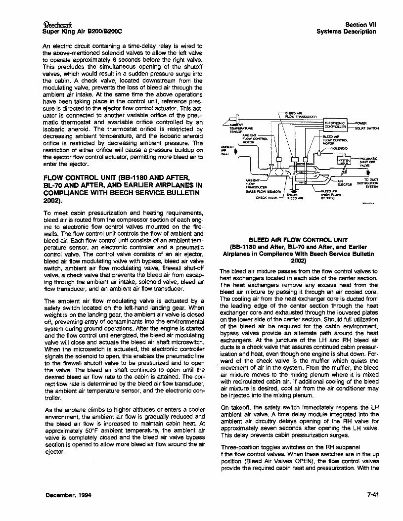
li?eechcraftSuper King Air B200/B200C
Section VIISystems Description
An electric circuit containing a time-delay relay is wired tothe above-mentioned solenoid valves to allow the left valveto operate approximately 13 seconds before the right valve.This precludes the simultaneous opening of the shutoffvalves, which would result in a sudden pressure surge intothe cabin. A check valve, located downstream from themodulating valve, prevents the loss of bleed air through theambient air intake. At the same time the above operationshave been taking place in the control unit, reference pressure is directed to the ejector flow control actuator. This actuator is connected to another variable orifice of the pneumatic thermostat and avariable orifice controlled by anisobaric aneroid. The thermostat orifice is restricted bydecreasing ambient temperature, and the isobaric aneroidorifice is restricted by decreasing ambient pressure. Therestriction of either orifice will cause a pressure buildup onthe ejector flow control actuator, permitting more bleed air toenter the ejector.
FLOW CONTROL UNIT (8B-1180 AND AFTER,BL-70 AND AFTER, AND EARUER AIRPLANES INCOMPLIANCE WITH BEECH SERVICE BULLETIN2002).
At.eIENTAIR &.INLET ~
PNEUMATICSHUT OFFVALVE
TO DUCTDISTRIBUTION
SYSTEM
To meet cabin pressurization and heating requirements,bleed air is routed from the compressor section of each engine to electronic flow control valves mounted on the firewalls. The flow control unit controls the flow of ambient andbleed air. Each flow control unit consists of an ambient temperature sensor, an electronic controller and a pneumaticcontrol valve. The control valve consists of an air ejector,bleed air flow modulating valve with bypass, bleed air valveswitch, ambient air flow modulating valve, firewall shut-offvalve, a check valve that prevents the bleed air from escaping through the ambient air intake, solenoid valve, bleed airflow transducer, and an ambient air flow transducer.
The ambient air flow modulating valve is actuated by asafety switch located on the left-hand landing gear. Whenweight is on the landing gear, the ambient air valve is closedoff, preventing entry of contaminants into the environmentalsystem during ground operations. After the engine is startedand the flow control unit energized, the bleed air modulatingvalve will close and actuate the bleed air shaft microswitch.When the microswitch is actuated, the electronic controllersignals the solenoid to open, this enables the pneumatic lineto the firewall shutoff valve to be pressurized and to openthe valve. The bleed air shaft continues to open until thedesired bleed air flow rate to the cabin is attained. The corre.ct flow rate is determined by the bleed air flow transducer,the ambient air temperature sensor, and the electronic controller.
As the airplane climbs to higher altitudes or enters a coolerenvironment, the ambient air flow is gradually reduced andthe bleed air flow is increased to maintain cabin heat. Atapproximately 50°F ambient temperature, the ambient airvalve is completely closed and the bleed air valve bypasssection is opened to allow more bleed air flow around the airejector.
December, 1994
BLEED AIR FLOW CONTROL UNIT(BB-1180 and After, BL-70 and After, and Earlier
Airplanes in Compliance With Beech Service Bulletin2002)
The bleed air mixture passes from the flow control valves toheat exchangers located in each side of the center section.The heat exchangers remove any excess heat from thebleed air mixture by passing 'it through an air cooled core.The cooling air from the heat exchanger core is dueted fromthe leading edge of the center section through the heatexchanger core and exhausted through the louvered plateson the lower side of the center section. Should full utilizationof the bleed air be required for the cabin environment,bypass valves provide an alternate path around the heatexchangers. At the juncture of the LH and RH bleed airduets is a check valve that assures continued cabin pressurization and heat, even though one engine is shut down. For-
) ward of the check valve is the muffler which quiets themovement of air in the system. From the muffler, the bleedair mixture moves to the mixing plenum where it is mixedwith recirculated cabin air. If additional cooling of the bleedair mixture is desired, cool air from the air conditioner maybe injected into the mixing plenum.
On takeoff, the safety switch immediately reopens the LHambient air valve. A time delay module integrated into theambient air circuitry delays opening of the RH valve forapproximately seven seconds after opening the LH valve.This delay prevents cabin pressurization surges.
Three-position toggles switches on the RH subpanelf the flow control valves. When these switches are in the upposition (Bleed Air Valves OPEN), the flow control valvesprovide the required cabin heat and pressurization. With the
7-41
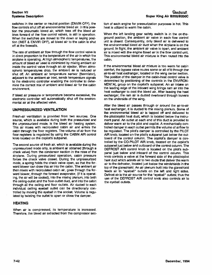
Section VIISystems Description
switches in the center or neutral position (ENVIR OFF), theflow controls shut off all environmental bleed air. In this position the pneumatic bleed air, which tees off the bleed airlines forward of the flow control valves, is still in operation.When the switches are moved to' the down or keying position (INST & ENVIR OFF), all bleed air to the cabin is shutoff at the firewalls.
The rate of ambient air flow through the flow control valve isin direct proportion to the temperature of the air in which theairplane is operating. At high atmospheric temperatures, theamount of bleed air used is minimized by mixing ambient airinside the control valve through an air ejector. When atmospheric temperatures drop, the ambient air is reduced orshut off. An ambient air temperature sensor (thermistor),adjacent to the ambient air inlet, sends temperature signalsto the electronic controller enabling the controller to determine the correct mix of ambient and bleed air for the cabinenvironment.
If bleed air pressure or temperature become excessive, theelectronic controller will automatically shut off the environmental air at the affected valve.
UNPRESSURIZED VENTILATION
Fresh-air ventilation is provided from two sources. Onesource, which is available during both the pressurized andthe unpressurized mode, is the bleed air heating system.This air mixes with recirculated cabin air and enters thecabin through the floor registers. The volume of.air from thefloor registers is regulated by using the CABIN AIR controlknob located on the copilot's subpanel.
The second source of fresh air, which is available during theunpressurized mode only, is ambient air obtained (through acheck valve) from the condensor section in the nose of theairplane. During pressurized operation, cabin pressureforces the check valve closed. During the unpressurizedmode, a spring holds the check valve open, so that the forward blower can draw this air into the cabin. The ambient airthen mixes with recirculated cabin air, goes through the forward blower, through the forward evaporator, (if it is operating, the air will be cooled), into the mixing plenum, into boththe ceiling-outlet and the floor-outlet duct, and into the cabinthrough all. the ceiling and floor outlets. Air duded to eachindividual ceiling eyeball outlet can be directionally controlled by moving the eyeball in the socket. Volume is regulated by twisting the outlet to open or close the damper.
HEATING
When air is compressed, its temperature is increased.Therefore, the bleed air extracted from the compressor sec-
7-42
~Super King Air B200/B200C
tion of each engine for pressurization purposes is hot. Thisheat is utilized to warm the cabin.
When the left landing gear safety switch is in the on-theground position, the ambient air valve in each flow controlunit is closed. Consequently, only bleed air is delivered tothe environmental bleed air duct when the airplane is on theground. In flight, the ambient air valve is open, and ambientair is mixed with the engine bleed air in the flow control unit.This environmental bleed air mixture is then routed into thecabin.
If the environmental bleed air mixture is too warm for cabincomfort, the bypass valve routes some or all of it through theair-to-air heat exchanger, located in the wing center section.The position of the damper in the cabin-heat control valve is
r. determined by positioning of the controls in the ENVIRONMENTAL group on the copilot's subpanel. An air intake onthe leading edge of the inboard wing brings ram air into theheat exchanger to cool the bleed air. After leaving the heatexchanger, the ram air is ducted overboard through louverson the underside of the wing.
After the bleed air passes through or around the air-to-airheat exchanger, it is ducted to the mixing plenum. Some ofthe environmental bleed air is tapped off and delivered tothe pilot/copilot heat duet, which is located below the instrument panel. An outlet at each end of this duct is provided todeliver warm air to the pilot and copilot. A mechanically controlled damper in each outlet permits the volume of airflow tobe regulated. The pilot's damper is controlled by the PILOTAIR knob, located on the pilot's subpanel just below the outboard of the control column. The copilot's damper is controlled by the CO-PILOT AIR knob, located on the copilot'ssubpanel just below and outboard of the control column. TheDEFROST AIR control knob is located on the pilot's subpanel just below and inboard of the control column. Thisknob controls a valve at the forward side of the pilot/copilotheat duct which admits air to two ducts that deliver the warmair to the defroster, located just below the windshields in thetop of the glareshield. An air plenum built into the glareshieldfeeds air to "eyeball" outlets on the left and right sides.Defrost air is the air source for the "eyeball" outlets; thus theuse of the DEFROST AIR control knob also controls air tothe eyeball outlets.
December, 1994
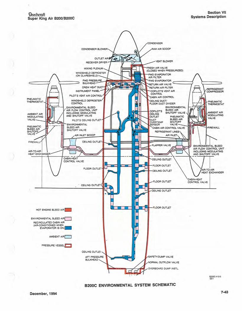
<DeechcraftSuper King Air B200/B200C
PNEUMATICTHERMOSTAT
AMBIENT AIRMODULATINGVALVE
FIREWALL I
AIR·To-AIRHEAT EXCHA GER
HOT ENGINE BLEED AIR
ENVIRONMENTAL BLEED AIRLJ
RECIRCULATED CABIN AIR(AIR·CONDITIONED WHEN
EVAPORATOR IS 0 )
AMBIENT AIRCJ
PRESSURE VESSE~
Section VIISystems Description
FRESH AIR VALVE(CLOSED WHEN PRESSURIZED)
FWD EVAPORATORAIR FILTER
~~~~~~II~il~~~FWD EVAPORATOR _-----1RETURN AIR VALVE -----..;RETURN AIR FILTER
COPILOTS VENT AIRCONTROL
CABIN AIR CONTROL
CEILING DUCTIFLOOR DUCT DIVIDER
ENVIRONMENTALBLEED AIRSHUTOFF VALVE
PNEUMATICBLEED AIRSHUTOFF
SENSOR VALVE -J{c~~~~CABI AIR CONTROL VALVE
REFRIGERANT LI ES
AIR I LET"
FLOOR OUTLET
SAFETYIDUMP VALVE
NORMAL OUTFLOW VALVE
OVERBOARD DUMP INSTL.
B2OOC·':10·500 1
December, 1994
8200C ENVIRONMENTAL SYSTEM SCHEMATIC
7-43
Section VIISystems Description
The remainder of the air in the environmental bleed air ductis discharged into the floor-outlet-duct section of the mixingplenum and mixed with recirculated cabin air. This air mixture is then ducted aft through the floor-outlet duct. If the airtemperature inside the duct becomes excessive, a sensorinside the duct causes the yellow DUCT OVERTEMP caution annunciator to illuminate. Refer to the ILLUMINATIONOF "DUCT OVERTEMP" ANNUNCIATOR procedure in theEMERGENCY PROCEDURES Section of this manual forcorrective action.
After passing the temperature sensor, the air passesthrough the cabin air control valve. This valve is controlledby the CABIN AIR control knob on the copilot's subpanel,just below and inboard of the control column. When thisknob is pulled out to the stop, only a minimum amount ofwarm air will be permitted to pass through the valve, therebyincreasing the amount of warm air available to the pilot andcopilot heat outlets, and to the defroster. When this knob ispushed fully in, the valve is open and the air in the duct willbe directed to the floor-outlet registers in the cabin.
RADIANT HEATING
A supplemental electric radiant heating system is availablefor cabin comfort. It is turned on and off by a switch in theENVIRONMENTAL group on the copilot's left subpanelplacarded RADIANT HEAT - OFF. This system can be usedin conjunction with an auxiliary power unit for warming thecabin prior to starting the engines, and it can be used assupplemental heat in flight. However, it should be used inconjunction with the manual temp control mode only.
On the B200C, a radiant heater element is installed in thecargo door. It is controlled by the Cabin Temperature Modeswitch and operates in all heating modes. This unit providessupplemental heat to the cabin for additonal passengercomfort.
AIR CONDITIONING SYSTEM
Cabin air conditioning is provided by a refrigerant-gas- .vapor-cycle refrigeration system consisting of: a belt-driven,engine-mounted compressor, installed on the right engineaccessory pad; refrigerant plumbing; an N1 speed switch;high- and low-pressure-protection switches; a condensorcoil; a condensor blower; an evaporator; a receiver-dryer; anexpansion valve; and a bypass valve. The plumbing fromthe compressor is routed through the right-wing inboardleading edge to the fuselage. It is then routed forward to thecondensor coil, receiver-dryer, expansion valve, bypassvalve, and evaporator, which are all located in the nose ofthe airplane.
The high- and low-pressure-limit switches and the N1 enginespeed switch are provided to prevent compressor operation
7-44
OeechcmftSuper King Air B200/B200C
outside of established limitation parameters. The N1 speedswitch will prevent the flow of electric current to the compressor clutch when the engine speed is below 62% N1.When the N1 speed switch is open and there is a demandfor air conditioning, the green AIR COND N1 LOW advisoryannunciator will illuminate. If either the high or low freonpressure limit is exceeded, an electronic system will causethe electronic circuit to trip and the reset switch light will illuminate. Reset switch and light are located in the nose gearwheel well. Depressing the reset switch one time mayrestore the airconditioning function. The switch is betweenthe power source and the electrically activated compressorclutch and condensor blower. The interruption of power willcause the compressor clutch and condenser blower to disengage. In the event the airconditioner does not work afterthe reset switch is depressed one time, the system shouldbe thoroughly checked. The compressor-clutch circuitbreaker is located in the D.C. power distribution panel insidethe lower forward equipment bay.
The forward evaporator utilizes a solenoid-operated hotgas-bypass valve to prevent icing. A 33°F thermal switch onthe forward evaporator controls the valve solenoid.
The forward vent blower blows recirculated cabin air (plusoutside ambient air if the cabin is unpressurized) through theforward evaporator, into the mixing plenum, and into boththe floor-outlet and ceiling-outlet ducts. If the cooling modeis operating, refrigerant will be circulating through the evaporator and the air leaving it will be cool. All the air entering theceiling-outlet duct will be cool. This air is discharged through"eyeball" outlet nozzles in the cockpit and cabin. Eachnozzle is movable, so that the airstream can be directed asdesired. When the nozzle is twisted, a damper opens orcloses to regulate airflow volume.
Cool air will enter the floor-outlet duct, but in order to providecabin pressurization, warm environmental bleed air will alsoenter the floor-outlet cJuct anytime either BLEED AIR valveis OPEN. Therefore, pressurized air discharged from thefloor registers will always be warmer than that discharged atthe ceiling outlets, no matter what temperature mode is inuse.
A vane-axial blower in the nose section draws ambient airthrough the condensor when the cooling mode is operating.This blower shuts off when the airplane is airborne. The current limiter for the blower is located in the DC power distributton panel in the lower forward equipment bay.
The receiver-dryer and sight gage are located high in thecondenser compartment. They can be viewed by removingthe upper-compartment access panel, located on top of thenose section just left of the centerline.
December, 1994
~ftSuper King Air B200/8200C
Section VIISystems Description
6200-410 -600 1
SIDEVIEW
CElLI G OUTLET
DOOR (COOLED AIR TOFLOOR OUTLETS)
-'---II.. Ii..... AFT EVAPORATORAIR FILTER
FRESH AIR VALVE(CLOSED WHEN PRESSURIZED)
FWD EVAPORATORAIR FILTER
'~~~ali~II~~~ FWD EVAPORATOR _-----1RETURN AIR VALVE -----~
RETURN AIR FILTER
COPILOTS VENT AIRCONTROL
CABIN AIR CONTROL
CElLI G DUCTtFLOOR DUCT DIVIDER
ENVIRO MENTALBLEED AIRSHUTOFF VALVE
P EUMATICBLEED AIR
SHUTOFF__Ja~~~1SE SOR VALVE
CABIN AIR CONTROL VALVE
REFRIGERANT LINES
AIR INLET\.
CEILING OUTLET
FLOOR OUTLET
WINDSHIELD DEFROSTERCONTROL
ENVIRO MENTAL BLEEDAIR FLOW CONTROL UNITINCLUDI G MODULATI GAND SHUTOFF VALVE
PILOTS CEILING OUTLET
ENVIRO MENTALBLEED AIRSHUTOFF VALVE
AMBIENT AIRc:J
PRESSURE VESSEL
HOT E GINE BLEED AIR
ENVIRONMENTAL BLEED AIRc=J
RECIRCULATED CABIN AIR(AIR-CONDITIONED WHEN
EVAPORATOR IS ON)
AMBlE T AIRMODULATINGVALVE
PNEU~MATIC • - - --BLEED AIRSHUTOFFVALVE
FIREWALL I \ I .IL-/--r--~AIR·TO·A IRHEAT EXCHANGER
PNEUMATICTHERMOSTAT
ENVIRONMENTAL SYSTEM SCHEMATIC(Optional Aft Evaporator System Shown)
December, 1994 7-45
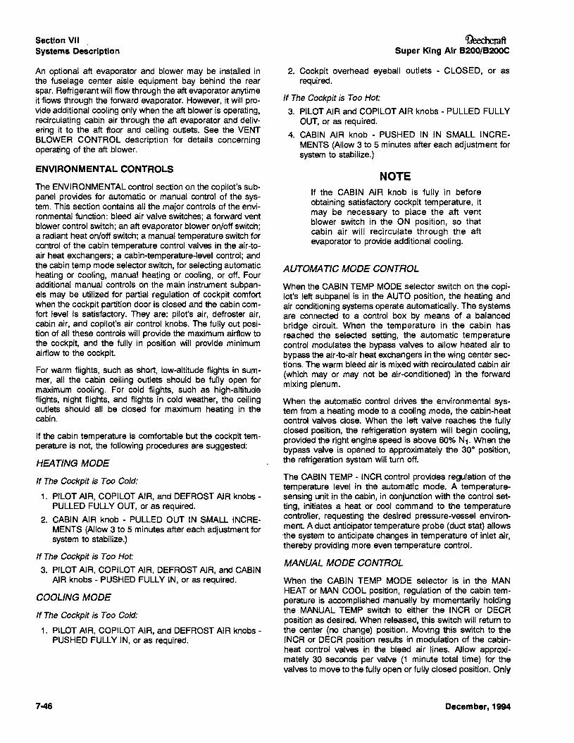
Section VIISystems Description
An optional aft evaporator and blower may be installed inthe fuselage center aisle equipment bay behind the rearspar. Refrigerant will flow through the aft evaporator anytimeit flows through the forward evaporator. However, it will provide additional cooling only when the aft blower is operating,recirculating cabin air through the aft evaporator and delivering it to the aft floor and ceiling outlets. See the VENTBLOWER CONTROL description for details concerningoperating of the aft blower.
ENVIRONMENTAL CONTROLS
The ENVIRONMENTAL control section on the copilot's subpanel provides for automatic or manual control of the system. This section contains all the major controls of the environmental function: bleed air valve switches; a forward ventblower control switch; an aft evaporator blower on/off switch;a radiant heat on/off switch; a manual temperature switch forcontrol of the cabin temperature control valves in the air-toair heat exchangers; a cabin-temperature-level control; andthe cabin temp mode selector switch, for selecting automaticheating or cooling, manual heating or cooling, or off. Fouradditional manual controls on the main instrument subpanels may be utilized for partial regulation of cockpit comfortwhen the cockpit partition door is closed and the cabin comfort level is satisfactory. They are: pilot's air, defroster air,cabin air, and copilot's air control knobs. The fully out position of all these controls will provide the maximum airflow tothe cockpit, and the fully in position will provide minimumairflow to the cockpit.
For warm flights, such as short, low-altitude flights in summer, all the cabin ceiling outlets should be fully open formaximum cooling. For cold flights, such as high-altitudeflights, night flights, and flights in cold weather, the ceilingoutlets should all be closed for maximum heating in thecabin.
If the cabin temperature is comfortable but the cockpit temperature is not, the following procedures are suggested:
HEATING MODE
If The Cockpit is Too .Cold:
1. PILOT AIR, COPILOT AIR, and DEFROST AIR knobs PULLED FULLY OUT, or as required.
2. CABIN AIR knob - PULLED OUT IN SMALL INCREMENTS (Allow 3 to 5 minutes after each adjustment forsystem to stabilize.)
If The Cockpit is Too Hot:
3. PILOT AIR, COPILOT AIR, DEFROST AIR, and CABINAIR knobs - PUSHED FULLY IN, or as required.
COOLING MODE
If The Cockpit is Too Cold:
1. PILOT AIR, COPILOT AIR, and DEFROST AIR knobs PUSHED FULLY IN, or as required.
7-46
OeechcmftSuper King Air B200/B200C
2. Cockpit overhead eyeball outlets - CLOSED, or asrequired.
If The Cockpit is Too Hot:
3. PILOT AIR and COPILOT AIR knobs - PULLED FULLYOUT, or as required.
4. CABIN AIR knob - PUSHED IN IN SMALL INCREMENTS (Allow 3 to 5 minutes after each adjustment forsystem to stabilize.)
NOTEIf the CABIN AIR knob is fully in beforeobtaining satisfactory cockpit temperature, itmay be necessary to place the aft ventblower switch in the ON position, so thatcabin air will recirculate through the aftevaporator to provide additional cooling.
AUTOMATIC MODE CONTROL
When the CABIN TEMP MODE selector switch on the copilot's left subpanel is in the AUTO position, the heating andair conditioning systems operate automatically. The systemsare connected to a control box by means of a balancedbridge circuit. When the temperature in the cabin hasreached the selected setting, the automatic temperaturecontrol modulates the bypass valves to allow heated air tobypass the air-to-air heat exchangers in the wing center sections. The warm bleed air is mixed with recirculated cabin air(which may or may not be air-conditioned) in the forwardmixing plenum.
When the automatic control drives the environmental system from a heating mode to a cooling mode, the cabin-heatcontrol valves close. When the left valve reaches the fullyclosed position, the refrigeration system will begin cooling,provided the right engine speed is above 60% N1. When thebypass valve is opened to approximately the 300 position,the refrigeration system will turn off.
The CABIN TEMP - INCR control provides regulation of thetemperature level in the automatic mode. A temperaturesensing unit in the cabin, in conjunction with the control setting, initiates a heat or cool command to the temperaturecontroller, requesting the desired pressure-vessel environment. A cuct anticipator temperature probe (duct stat) allows-the system to anticipate changes in temperature of inlet air,thereby providing more even temperature control.
MANUAL MODE CONTROL
When the CABIN TEMP MODE selector is in the MANHEAT or MAN COOL position, regulation of the cabin temperature is accomplished manually by momentarily holdingthe MANUAL TEMP switch to either the INCR or DEeRposition as desired. When released, this switch will return tothe center (no change) position. Moving this switch to theINCR or DEeR position results in modulation of the cabinheat control valves in the bleed air lines. Allow approximately 30 seconds per valve (1 minute total time) for thevalves to move to the fully open or fully closed position. Only
December, 1994
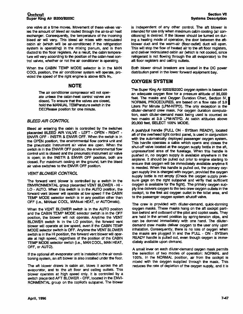
OeecmaftSuper King Air B200!B20OC
one valve at a time moves. Movement of these valvesvaries the amount of bleed air routed through the air-to-air heatexchanger. Consequently, the temperature of the incomingbleed air will vary. This bleed air mixes with recirculatedcabin air (which will be air-conditioned if the refrigerationsystem is operating) in the mixing plenum, and is thenducted to the floor registers. As a result, the cabintemperature will vary according to the positionof the cabin-heat centrol valves, whether or not the air conditioner is operating.
When the CABIN TEMP MODE selector is in the MANCOOL position, the air conditionersystem will operate, provided the speed of the right engine is above 600" N1.
NOTEThe air conditioner compressorwill not operate unless the cabin-heat control valves areclosed.To ensure that the valvesare closed,hold the MANUAL TEMPerature switch in theDECRease position for one minute.
BLEEDAIR CONTROL
Bleed air entering the cabin is controlled by the switchesplacarded BLEED AIR VALVE - LEFT - OPEN - RIGHT ENVIR OFF -INSTR &ENVIR OFF. When the switch is inthe OPEN position, the environmental flow control unit andthe pneumatic instrument air valve are open. When theswitch is in the ENVIR OFF position, the environmental flowcontrol unit is closed and the pneumaticinstrument air valveis open; in the INSTR & ENVIR OFF position, both areclosed. For maximum cooling on the ground, tum the bleedair valve switches to the ENVIR OFF position.
VENTBLOWER CONTROL
The forward vent blower is controlled by a switch in theENVIRONMENTAL group placardedVENT BLOWER - HI LO - AUTO. When this switch is in the AUTO position, theforward vent blower will operate at low speed if the CABINTEMP MODE selector switch is in any position other thanOFF (Le., MANual COOL, MANual HEAT, or AUTOmatic).
When the VENT BLOWER switch is in the AUTO positionand the CABIN TEMP MODE selector switch is in the OFFposition, the blower will not operate. Anytime the VENTBLOWER switch is in the LO position, the forward ventblower will operate at low speed, even if the CABIN TEMPMODE selectorswitch is OFF. Anytimethe VENT BLOWERswitch is in the HI position, the forwardvent blowerwin operate at high speed, regardless of the position of the CABINTEMP MODE selector switch (i.e., MANCOOL, MANHEAT,OFF, or AUTO).
If the optional aft evaporatorunit is installedin the air conditioning system, an aft bloweris also installedunderthe floor.
The aft blower draws in cabin air, blows it across the aftevaporator, and to the aft floor and ceiling outlets. Thisblower operates at high speed only. It is controlled by aswitch placarded AFT BLOWER - OFF, located in the ENVIRONMENTAL group on the copilot's subpanel. The blower
April, 1996
Section VIISystems Description
is independent of any other control. The aft blower isintended for use only when maximum cabincooling (air conditioning) is desired. If the blower should be tumed on during a heating mode of operation, the door between the.aftblower duct and the wann-air (floor-outlet) duct will open.This will stop the flow of heated air to the aft floor registers,and deliver recirculated cabin air (which is not cooled, sincerefrigerant is not flowing through the aft evaporator) to theaft floor registers and ceiling outlets.
Both blower circuit breakers are located in the DC powerdistribution panel in the lower forward equipmentbay.
OXYGEN SYSTEM
The Super KingAir B200/B200C oxygensystem is based·onan adequate oxygen flow for a pressure altitude of 35,000feel The masks and Oxygen Duration Chart, Section IV,INORMAL PROCEDURES, are based on a flow rate of 3.9Uters Per Minute (LPM-NTPD). The only exception is thediluter-demand crew mask. For oxygen duration computation, each diluter-demand mask being used is counted astwo masks at 3.9 LPM-NTPD. At cabin altitudes above20,000 feet, SELECT 1000" MODE.
A push/pull handle (PULL ON - SyStem READY), locatedaft of the overhead light control panel, is used in conjunctionwith the automatically deployed passenger oxygen system.This handle operates a cable which opens and closes theshut-off valve located at the oxygen supply bottle in the aft,unpressurized area of the fuselage. When this handle ispushed in, no oxygen supply is available anywhere in theairplane. It should be pUlled out prior to engine starting toensure that oxygen will be immediately available anytime itis needed. When this handle is pulled out, the primary oxygen supply line is charged withoxygen, providedthe oxygensupply bottle is not empty (Check the oxygen supply pres...sure gage on the right subpanel and verify that sufficientoxygen is available for the flight). The primary oxygen supply line delivers oxygento the two crew oxygen outlets in thecockpit, to the first aid oxygen outlet in the toilet area, andto the passenger oxygen system shutoff valve.
The crew is provided with diluter-demand, quick-donningoxygen masks. These masks hang on the aft cockpit partition behind and outboardof the pilot and copilot seats. Theyare held in the armed position by spring-tension clips, andcan be donned immediately with one hand. The diluterdemand crew masks deliver oxygen to the user only uponinhalation. Consequently. there is no loss of oxygen whenthe masks are plugged in and the PULL - ON - SYStemREADY handle is pulled out, even though oxygen is immediately available upon demand.
A small lever on each diluter-demandoxygen mask permitsthe selection of two modes of operation: NORMAL and'100%. In the NORMAL position, air from the cockpit ismixed with the oxygen supplied through the mask. This,reduces the rate of depletionof the oxygensupply, and it is
7-47
Section VIISystems Description
more comfortable to use than 1OOO" aviators breathing oxygen. However, in the event of smoke or fumes in the cockpit, the 100% position should be used to preventthe breathing of contaminated air. For this reason, the selector levershould be left in the 100% position when the masksare notin use.
Anytime the primary oxygen supply line is charged, oxygencan be obtained from the first aid oxygen mask located inthe toilet area, by manually opening the overhead accessdoor (placarded FIRST AID OXYGEN - PULL) and openingthe ON-OFF valve inside the box. A placard (NOTE: CREWSYStem MUST BE ON) reminds the user that the PULLON- SyStem READYhandle in the cockpit must be pulled outbeforeoxygenwill flow from the first aid oxygen mask.
The passenger oxygen system is of the constant flow type.Anytime the cabin pressure altitude exceeds approximately12,500 feet, a barometric-pressure switch automaticallyenergizes a solenoid which opens the passenger oxygensystem shut-offvalve.The pilot can open the valve manuallyanytime by pUlling out the PASSENGER MANUAL OverRIDEhandle, located aft of the overhead light control panel.Oncethe passengeroxygen system shut-off valve hasbeenopened (either automatically or manually), oxygen will flowinto the passengeroxygensupply line, ifthe primaryoxygensystem line has been charged (i.e., if the oxygen supplybottlecontains oxygen and the PULL ON - SYStem READYhandlein the cockpit is pulled out). When oxygenflows into
7-48
Ci?eechcmftSuper King Air B200/B200C
the passenger oxygen system supply line, a pressuresensitive switch in the line closes a circuit to illuminate thegreen PASS OXYGEN ON annunciator on the cautionary!advisory annunciator panel. This switch will also cause thecabin lights (all fluorescent lights, the foyer light and thecenter baggage compartment light) to illuminate in the fullbright mode, regardless of the position of the interior lightsswitch placarded CABIN UGHTS - START BRIGHT- DIM OFF locatedon the copilot's left subpanel.
The pressure of the oxygen in the passengeroxygensystemsupply line then automatically extends a plunger againsteach of the passenger oxygen mask dispenser doors, forcing the doors open. The oxygen masks then drop downabout 9 inchesbelow the dispensers. The lanyardvalve pinat the top of the oxygen mask hose must be pulled out inorder for oxygen to flow from the mask. The pin is connected to the oxygen mask via a flexible cord; when theoxygen mask is pulled down for use, the cord pulls the pinout of the lanyard valve. The lanyard valve pin must bemanually reinserted into the valve in order to stop the flowof oxygen when the mask is no longer needed. The passenger oxygen can be shut off and the remaining oxygen isolatedto the creNand first aid outletsby pUlling the OXYGENCONTROLcircuit breaker in the ENVIRONMENTAL groupon the right side panel, providing the PASSENGER MANUAL O'RIDE handle is pushed in to the OFF position.
December, 1994
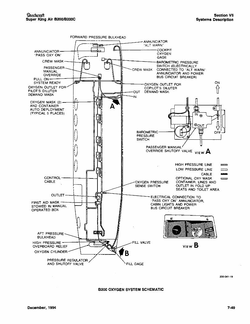
Ci?eechcmftSuper King Air B200/B200C
Section VIISystems Description
FORWARD PRESSURE BULKHEAD
ON
~
VIEW B
ELECTRICAL CONNECTION TO"PASS OXY ON" ANNUNCIATOR,CABIN LIGHTS AND POWERBUS CIRCUIT BREAKER
PASSENGER MANUALOVERRIDE SHUTOFF VALVE VIEW A
BAROMETRIC----.:;PRESSURESWITCH
HIGH PRESSURE LINE :zzzzzJ
LOW PRESSURE LINE :::::J
CABLE -OPTIONAL OXY MASK ~
OXYGEN PRESSURE CONTAINER, LINES ANDSENSE SWITCH OUTLET IN FOLD UP
SEATS AND TOILET AREA
FILL VALVE
ANNUNCIATOR"ALT WARN"
o-~-------COCKPIT
OXYGENGAGE
IJl\\-~-------BAROMETRIC PRESSURESWITCH (ELECTRICALLY
CREW MASK CONNECTED TO "ALT WARN"ANNUNCIATOR AND POWERBUS CIRCUIT BREAKER)
~~----OXYGEN OUTLET FORCOPILOT'S DILUTER
~=~==:tll--OUT DEMAND MASK
~=JJ::~:;::::a:J~~I-- IN
CONTROL ----t---oM---I
CABLE
AFT PRESSUREBULKHEAD
HIGH PRESSUREOVERBOARD RELIEF
OXYGEN CYLINDER
OUTLET-----t--,-~_~,g
FIRST AID MASK -----t--t--to!--"'fI!
STOWED IN MANUALOPERATED BOX
OXYGEN MASK (2)---H-~--1T1AND CONTAINERAUTO DEPLOYMENT(TYPICAL 5 PLACES)
ANNUNCIATOR ---+-t----t::=__-'"PASS OXY ON"
CREW MASK-----t_-L~
PASSENGERMANUALOVERRIDE
PULL ON ------+--11----.'"SYSTEM READY
OXYGEN OUTLET FORPILOT'S DILUTERDEMAND MASK
PRESSURE REGULATORAND SHUTOFF VALVE FILL GAGE
200-341-19
B200 OXYGEN SYSTEM SCHEMATIC
December, 1994 7-49
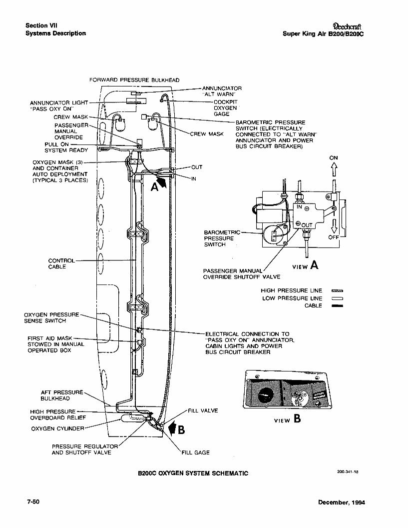
Section VIISystems Description
OeechcmftSuper King Air B200/B200C
ON
~
VIEwA
BAROMETRIC -_-..IUPRESSURESWITCH
PASSENGER MANUALOVERRIDE SHUTOFF VALVE
OUT
IN
CREW MASK
J[fl3~R"t--------BAROMETRIC PRESSURESWITCH (ELECTRICALLYCONNECTED TO "ALT WARN"ANNUNCIATOR AND POWERBUS CIRCUIT BREAKER)
I I
\J
f":VnU10. 'I.' ~\)
FORWARD PRESSURE BULKHEAD
!C--2i;f\'I '\ ~__---.J111v rr
CONTROL__-#...L------t~
CABLE
OXYGEN MASK (3)---.;..---~AND CONTAINERAUTO DEPLOYMENT(TYPICAL 3 PLACES)
ANNUNCIATOR LIGHT"PASS QXY ON""
CREW MASK
PASSENGERMANUALOVERRIDE
PULL ON---~~~-_"""'ISYSTEM READY
ELECTRICAL CONNECTION TO"PASS OXY ON" ANNUNCIATOR,CABIN LIGHTS AND POWERBUS CIRCUIT BREAKER
OXYGEN PRESSURESENSE SWITCH
FIRST AID MASK ---1---+-~_..JLLM~lSTOWED IN MANUALOPERATED BOX
AFT PRESSUREBULKHEAD
HIGH PRESSURE -----\...---.J~;;;;;:~~l...
OVERBOARD RELIEF
OXYGEN CYLINDER
FILL VALVE
HIGH PRESSURE LINE ~
LOW PRESSURE LINE ::::=J
CABLE -
~, ~ ~~~ .
..VIEW B
PRESSURE REGULATORAND SHUTOFF VALVE FILL GAGE
B200C OXYGEN SYSTEM SCHEMATIC 200-341-18
7-50 December, 1994
0eed1cmftSuper King Air B200/B200c
PITOT AND STATIC SYSTEM
The pitot and static system provides a source of impact airand static air for operationof the flight instruments. A heatedpitot mast is located to each side of the lower portion of thenose. Tubing from the left pitot mast is connected to thepilot's airspeed indicator,andtubingfromthe rightpitot mastis connected to th~ copilot's airspeed indicator.
The normal static system providestwo separate sources ofstatic air - one for the pilot's flight instruments, and one forthe copilot's. Each of the normalstaticair lines opens to theatmosphere through two static air ports - one on each sideof the fuselage.
An alternate static air line is also provided for the pilafs flightinstruments. In the event of a failure of the pilot's normalstatic air source (e.g., if ice accumulations should obstructthe static air ports), the altemate sourceshould be selectedby lifting the spring-clip retaineroffthe PILOT'SSTATICAIRSOURCE valve handle, locatedon the right side panel, andmoving the handle aft to the ALTERNATE position.This willconnect the altemate static air line to 1he pilafs flight instruments. The alternate line obtainsstaticair just aft of the rearpressure bulkhead, from inside the unpressurized area ofthe fuselage.
The pilot's altimeter, vertical speed indicator, and airspeedindicator are connectedto the pilafs staticair source. Whenthe system is switchedto the pilot'saltemateair source, thepilot's altimeter and vertical speed indicatorare affected as
April, 1996
Section VIISystems Description
well as the pilot'sairspeed indicator. The copilot's airspeedindicator, altimeter, and vertical speed indicator are all onthe copilot's static air source and cannot be switched toalternate source. See SCHEMATIC DIAGRAM of PITOTAND STATIC SYSTEM.
The pilot'sairspeed and altimeter indicationschange whenthe alternatestatic air source isin use. Refer to the Airspeed Calibration Alternate System, and the Altimeter Correc-tion - Altemate System graph in Section V, IPERFORMANCE for operation when thealternate static air source is in use.
When the altemate static air source is not needed, ensurethat the PILOrS STATIC AIR SOURCEvalve handle is heldin the forward(NORMAL) positionby the spring-clip retainer.
Three petcocks are provided to facilitate draining moisturefrom the staticair lines. They are located behind an accesscover belowthe circuit breakers on the right side panel. Thedrainvalvesshould be opened to release any trapped moisture at each 150-hourinspection, and after exposure to visible moistur9 on the ground. They must be closed afterdraining.
7-51
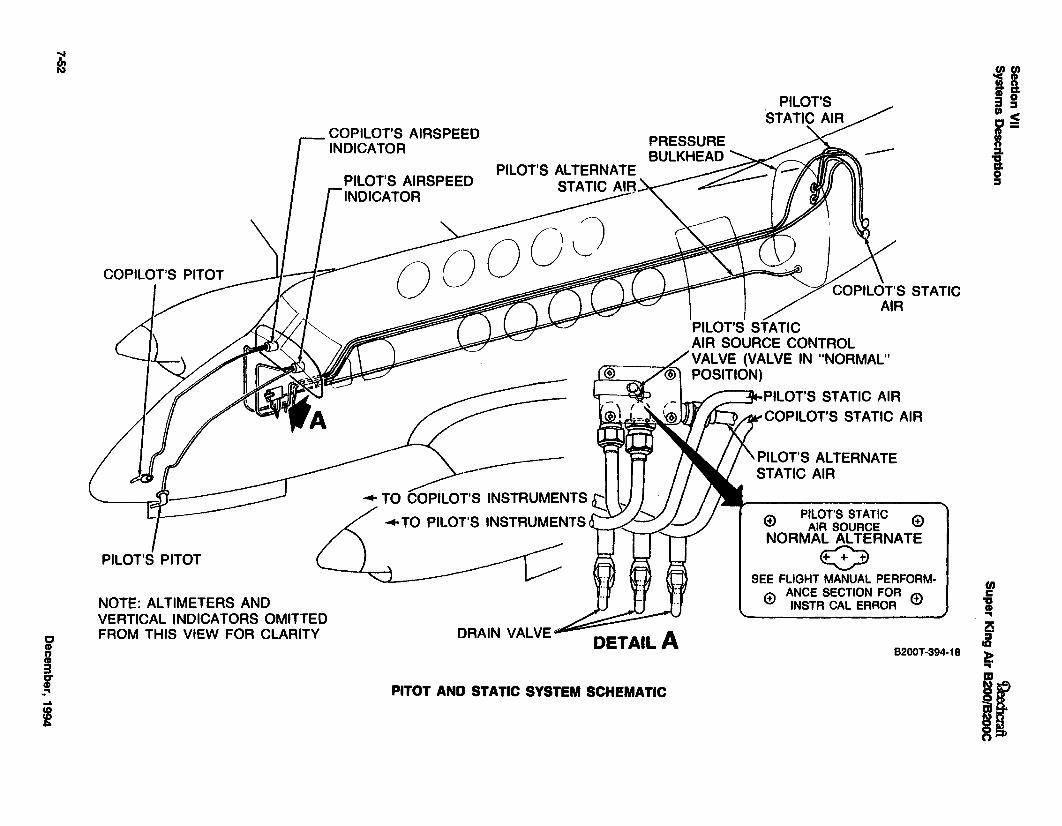
PITOT AND STATIC SYSTEM SCHEMATIC
!If1&a 0en :s
i'~n::L
Io::I
UJc
"CD...2Si~..If~[
COPILOT'S STATICAIR
8200T ·394·18
PILOT'S'STATIC~
@ PILOT'S STATIC 4'AIR SOURCE \:::J
NORMAL ALTERNATE
osee FLIGHT MANUAL PERFORM·
<t> ANCE SECTION FOR <±>INSTA CAL ERROR
PILOT'S STATICAIR SOURCE CONTROLVALVE (VALVE IN "NORMAL"POSITION)
PILOT'S STATIC AIR
~COPilOT'S STATIC AIR
PILOT'S ALTERNATESTATIC AIR
DETAIL A
PILOT'S ALTERNATESTATIC AI~ ___
DRAIN VALVE ..
• TO COPilOT'S INSTRUMENTS tj..TO PILOT'S INSTRUMENTS A.-
PILOT'S AIRSPEEDINDICATOR
COPILOT'S AIRSPEEDINDICATOR
PILOT'S PITOT
NOTE: ALTIMETERS ANDVERTICAL INDICATORS OMITTEDFROM THIS VIEW FOR CLARITY
~
~
i'nCD:Ii........I
CileechcmftSuper King Air B200/B200C
ENGINE BLEED AIR PNEUMATICSYSTEM
High-pressure bleed air from each engine compressor,routed through the firewall shutoff valves and regulated at18 psi, supplies pressure for surface deice system andvacuum source. Vacuum for the flight instruments is derivedfrom a bleed air ejector. One engine can supply sufficientbleed air for all these systems.
During single-engine operation, a check valve in the bleedair line from each engine prevents flow back through the lineon the side of the inoperative engine. A suction gage calibrated in inches of mercury, located on the copilot's subpanel, indicates instrument vacuum. To the right of the suction gage is a pneumatic pressure gage, calibrated inpounds per square inch, which indicates air pressure available to the deice distributor valve.
Refer to the Pneumatic Bleed Air and Surface Deice SystemSchematic.
BLEED AIR WARNING SYSTEM
The bleed air lines from the engines to the cabin areshielded with insulation to protect other components fromheat. Heat is also dissipated in the air-to-air heat exchangerin the center wing section. The bleed air lines are accompanied in close proximity by plastic tubing from the engines tothe cabin. One end of the tubing is plugged off; the otherend is connected to a bleed air source in the cabin, to supply the line with pressure. Excessive heat on the plastic tubing caused by a ruptured bleed air line will cause the tubingto fail. Upon release of pressure in the tubing, a normallyopen switch in the line, located under the copilot's floor inthe fuselage, will close, causing a circuit to be completed tothe respective BL AIR FAIL light in the warning annunciatorpanel. When the indication of bleed air line failure becomesevident, the bleed air for that side should be turned off byplacing the respective lever-lock BLEED AIR VALVE switchon the copilot's subpanel in the INSTR &ENVIR - OFF position.
AUTOMATIC DEVICES IN THE CONTROLSYSTEM
YAW DAMP
A yaw damp system is provided to aid the pilot in maintainiAg directional control, and to increase ride comfort. The system may be used at any altitude, and is required for flightabove 17,000 feet. It should be deactivated for takeoff andlanding.
If the system is equipped with an autopilot, the yaw dampsystem will be a part of the autopilot. Operating instructionsfor this system will be contained in the appropriate AirplaneFlight Manual Supplement.
If an autopilot is not installed in the airplane, yaw damping isprovided by an independent yaw damp system. The components include a yaw sensor, amplifier, and control valve.Regulated air pressure from the control valve is directed to
December, 1994
Section VIISystems Description
the same pneumatic servos used for the rudder boost system. The system (on airplanes without an autopilot) is controlled by a YAW DAMP switch adjacent to the RUDDERBOOST switch on the pedestal. In the event the YAWDAMP switch is inadvertently left ON during takeoff or landing, the circuit for the yaw damping system will be interrupted by the left landing gear safety switch while the airplane is on the ground, rendering it inoperative.
STALL WARNING SYSTEM
The stall warning system consists of a transducer, a lift computer, a warning horn, and a test switch. Angle of attack issensed by aerodynamic pressure on the lift transducer vanelocated on the left wing leading edge. When a stall is imminent, the output of the transducer activates a stall warninghorn.
The system has preflight capability through the the use of aswitch placarded STALL WARN - TEST - OFF on the copilot's left subpanel. Holding this switch in the TEST positionactivates the warning horn.
ICE PROTECTION SYSTEMS
WINDSHIELD HEAT
Windshield heat switches are located on the pilot's subpanel(inboard) and are placarded ICE - WSHLD ANTI-ICE - NORMAL - OFF - HI - PILOT - COPILOT.
Two levels of heat are provided. When the switches are inthe NORMAL (up) position, heat is supplied to the majorportion of the windshields. When they are in the HI (down)position, a higher level of heat is supplied to a smaller areaof the windshields. Each switch must be lifted over a detentbefore it can be moved into 'the HI position. This lever-lockfeature prevents inadvertent selection of the HI positionwhen moving the switches from NORMAL to the OFF (center) position.
Controllers with temperature-sensing units provide forproper heat at the windshield surfaces. Five-ampere circuitbreakers, located on a panel on the forward pressure bulkhead, protect the control circuits. The power circuit of eachsystem is protected by a 50-ampere circuit breaker located
) in the power distribution panel under the floor forward of themain spar.
NOTEErratic operation of the magnetic compassmay occur while windshield heat is beingused.
PROPELLER ELECTRIC DEICE SYSTEM
PRIOR TOBB-829, AND PRIOR TO BL-37:
The propeller electric deice system includes: an electricallyheated boot with two elements, (inner and outer) for each
7·53
Section VIISystems Description
propeller blade, brush assemblies, slip rings, an ammeter, atimer for automatic operation, and a circuit for manual control for backup.
A 20-ampere circuit breaker switch on the pilot's subpanel,placarded PROP - AUTO - OFF, is provided to activate theautomatic system. A deice ammeter on the right subpanelregisters the amount of current (14 to 18 amperes) passingthrough the system being used. During AUTO operation,power to the timer will be cut off if the current rises abovethe circuit breaker switch rating. Current flows from the timerto the brush assembly and then to the slip rings installed onthe spinner backing plate. The slip rings carry the current tothe deice boots on the propeller blades. Heat from the bootsreduces the grip of the ice, which is then thrown off by centrifugal force aided by the air blast over the propeller surfaces. Power to the two heating elements on each blade, the (inner and outer element, is cycled by the timer in the following sequence: right propeller outer elements, right propellerinner elements, left propeller outer elements, and left propeller inner elements. Loss of one heating element on one sidedoes not mean that the entire system will be inoperative.
Proper operation can be checked by noting the correct levelof current usage on the ammeter. An intermittent flicker ofthe needle approximately every 30 seconds indicatesswitching to the next group of heating elements by the timer.
The manual prop deice system is provided as a backup tothe automatic system. A control switch located on the leftsubpanel, placarded PROP - INNER - OUTE~, controls themanual override relays. When the switch is in the OUTERposition, the automatic timer is overridden and power is supplied to the outer elements of both propellers simultaneously. The switch is of the momentary type and must beheld in position until the ice has been dislodged from thepropeller surface. After deicing with the outer elements, theswitch must be held in the INNER position to perform thesame function for the inner elements of both propellers. Theloadmeters will indicate approximately a .05 increase of loadper meter when manual prop deice is operating. The propdeice ammeter will not indicate any load in the manual modeof operation.
7-54
~Super King Air B200/B200C
B8-829 AND AFTER, BL-37 AND AFTER:
The propeller electric deice system includes: electricallyheated deice boots, slip rings and brush block assemblies,a timer for automatic operation, an ammeter, three circuitbreakers located on the fuel control panel for left and rightpropeller and control circuit protection, and two switcheslocated on the pilot's subpanel for automatic or manual control of the system.
A circuit breaker switch located on the pilot's subpanel, placarded PROP - AUTO - OFF, is provided to activate the automatic system. Upon placing the switch to the AUTO position,the timer diverts power through the brush block and slip ringto all heating elements on one propeller. Subsequently, thetimer then diverts power to all heating elements on ·the otherpropeller for the same length of time. This cycle will continueas long as the switch is in the AUTO position. The systemutilizes a metal foil type single heating element energized byDC voltage. The timer switches every 90 seconds, resultingin a complete cycle in approximately 3 minutes.
A manual prop deice system is provided as a backup to theautomatic system. A control switch located on the left subpanel, placarded PROP - MANUAL - OFF, controls the manual override relay. Upon placing the switch is in the MANUAL position, the automatic timer is overridden and power isthen supplied to the heating elements of both propellerssimultaneously. This switch is of the momentary type andmust be held in position for aproximately 90 seconds to dislodge from the propeller surface. Repeat this procedure asrequired to avoid significant buildup of ice which will result inloss of performance, vibration, and impingement upon thefuselage. The prop deice ammeter will not indicate a loadwhile the propeller deice system is being utilized in the manual mode. However, the loadmeters will indicate an approximate .05 increase of load per meter while the manual propdeice system is operating.
December, 1994
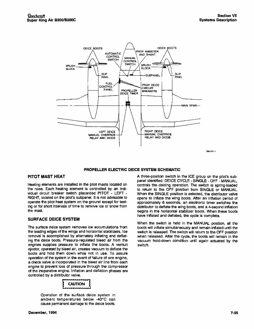
~chcmft .Super King Air B200/B200C
Section VIISystems Description
MAIN SPAR-
RIGHT DEICEMANUAL OVERRIDERELAY AND DIODE
DEICE BOOTSPROP AMMETER
AND SHUNT
FUEL/CONTROL
PANEL PROPELLERDEICE TIMER
~l
LEFT DEICEMANUAL OVERRIDERELAY AND DIODE
DEICE BOOTS
BRUSH__.........BLOCK
-- ------+-
200-:!51·1
Heating elements are installed in the pitot masts located onthe nose. Each heating element is controlled by an individual circuit breaker switch placarded PITOT - LEFT RIGHT, located on the pilot's subpanel. It is not advisable tooperate the pitot heat system on the ground except for testing or for short intervals of time to remove ice or snow fromthe mast
The surface deice system removes ice accumulations fromthe leading edges of the wings and horizontal stabilizers. Iceremoval is accomplished by alternately inflating and deflating the deice boots. Pressure-regulated bleed air from theengines supplies pressure to inflate the boots. A venturiejector, operated by bleed air, creates vacuum to deflate theboots and hold them down while not in use. To assureoperation of the system in the event of failure of one engine,a check valve is incorporated in the bleed air line from eachengine to prevent loss of pressure through the compressorof the inoperative engine. Inflation and deflation phases arecontrolled by a distributor valve.
[~
PITOT MAST HEAT
SURFACE DEICE SYSTEM
PROPELLER ELECTRIC DEICE SYSTEM SCHEMATIC
A three-position switch in the ICE group on the pilot's subpanel identified: DEICE CYCLE - SINGLE - OFF - MANUAL,controls the deicing operation. The switch is spring-loadedto return to the OFF position from SINGLE or MANUAL.When the SINGLE position is selected, the distributor valveopens to inflate the wing boots. After an inflation period ofapproximately 6 seconds, an electronic timer switches thedistributor to deflate the wing boots, and a 4-second inflationbegins in the horizontal stabilizer boots. When these bootshave inflated and deflated, the cycle is complete.
When the switch is held in the MANUAL position, all theboots will inflate simultaneously and remain inflated until theswitch is released. The switch will return to the OFF positionwhen released. After the cycle, the boots will remain in thevacuum hold-down condition until again actuated by theswitch.
Operation of the surface deice system inambient temperatures below -40°C cancause permanent damage to the deice boots.
December, 1994 7·55
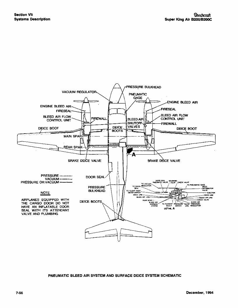
VACUUM REGULATOR
Section VIISystems Description
ENGINE BLEED AIR~ IFIRESEAL ~
BLEED AIR FLOWCONTROL UNIT
DEICE BOOT
PRESSURE --------VACUUM ----
PRESSURE OR VACUUM---
NOTE-AIRPLANES EQUIPPED WITHTHE CARGO DOOR DO NOTHAVE AN INFLATABLE DOORSEAL WITH ITS ATIENDANTVALVE AND PLUMBING
DOOR SEAL
--PRESSUREBULKHEAD
~Super King Air B200/B200C
\ -~E;NGINE BLEED AIR
~~RRESEAL
BLEED AIR FLOWCONTROL UNIT
......~-...-..--FIREWALL
DEICE BOOT
BRAKE 0 CE VALVE
DOORSEAL SOLENOIDTO VACUUM PNEUMATICVALVE VALVE CHECK VAlVE
REGULATOR~ \ TO PNEUMATIC GAGE
TO:~ ~ {ge~BUTORTO FUGHT HOUR.__~ VALVE
METERSWlTCH~" EJECTORoelCE LINE DEICE UNE
BLEEDAIR UNE BLEEDAlA LINE
REAR SPAR- - - CHECK VALVEBLEEDAIR BLEED AIRWARNING ICE PRESSURE
SYSTEM LINE REGULATOR
7-56
PNEUMATIC BLEED AIR SYSTEM AND SURFACE DEICE SYSTEM SCHEMATIC
December, 1994
OeechcraftSuper King Air B200/B200C
For most effective deicing operation, allow at least 1/2 inchof ice to form before attempting ice removal. Very thin icemay crack and cling to the boots instead of shedding. Subsequent cyclings of the boots will then have a tendency tobuild up a shell of ice outside the contour of the leadingedge, thus making ice removal efforts ineffective.
STALL WARNING VANE HEAT
The lift transducer is equipped with anti-icing capability onboth the mounting plate and the vane. The heat is controlledby a switch in the ice group located on the pilot's right subpanel identified: STALL WARN. The level of heat is minimalfor ground operation, but is automatically increased for flightoperation through the left landing gear safety switch.
IWARNING IThe heating elements protect the lift transducer vane and face plate from ice. However, a buildup of ice on the wing maychange or disrupt the airflow and prevent thesystem from accurately indicating an imminent stall. Remember that the stall speedincreases whenever ice accumulates on anyairplane.
FUEL HEAT
An oil-to-fuel heat exchanger, located on the engine accessory case, operates continuously and automati~ly to heatthe fuel sufficiently to prevent ice from collecting in the fuelcontrol unit when the procedure under "APPROVED FUELADDITIVE" located in LIMITATIONS Section is compliedwith.
Each pneumatic fuel control line is protected against ice byan electrically heated jacket. Power is supplied to each fuelcontrol air line jacket heater by two switches actuated bymoving the condition levers in the pedestal out of the fuelcutoff range. Fuel control heat is automatically turned on forall flight operations.
COMFORT FEATURES
TOILET
The side facing toilet is installed in the foyer and faces theairstair door. The foyer can be closed off from the cabin bysliding the two partition-type door panels to the center of thefuselage, where they are held closed by magnetic strips. Aforward facing toilet, when installed, is located in the aftcargo area and is enclosed by the cargo partition. The toiletmay be either the chemical type or the electrically flushingtype. In either case, the two hinged lid half-sections must beraised to gain access to the toilet. A toilet tissue dispenseris contained in a slide-out compartment on the forward sideof the toilet compartment.
December, 1994
Section VIISystems Description
If a Monogram electrically flushing toilet isinstalled, the sliding knife valve should beopen at all times, except when actually servicing the unit. The cabinet below the toiletmust be opened in order to gain access tothe knife valve actuator handle.
RELIEF TUBES
A relief tube is contained in a special tilt-out compartment atthe aft side of the toilet cabinet. A relief tube may also beinstalled in the cockpit and stowed under the pilot or copilotchair. The hose on the cockpit relief tube is of sufficientlength to permit use by either pilot or copilot.
A valve lever is located on the side of the relief tube horn.This valve lever must be depressed at all times while therelief tube is in use. Each tube drains into the atmospherethrough its own special drain port, which protrudes from thebottom of the fuselage. Each drain port atomizes the discharge to keep it away from the skin of the airplane.
NOTEThe relief tubes are for use during flight only.
CABIN FEATURES
FIRE EXTINGUISHERS
An optional portable fire extinguisher may be installed on thefloor on the left side of the airplane forward of the airstairentrance door, just aft of the rearmost seat. Another onemay also be installed underneath the copilot's seat.
WINDSHIELD WIPERS
The dual windshield wiper installation consists of an electricmotor, arm and wiper assemblies, drive shafts, and converters, all located forward of the instrument panel. The systemalso includes a control switch, located in the upper left cor-
J ner of the overhead light control panel, and a circuit breakerlocated on the right circuit breaker panel. The control knob,placarded WINDSHIELD WIPER - PARK - OFF - SLOW FAST, controls the wipers. The wipers have two speeds,one for light and one for heavy precipitation. After the control is turned to PARK to bring the wiper arms to their mostinboard position, spring-loading returns the control to theOFF position.
Windshield wipers may be used during either ground orflight operations.
7·57
Section VIISystems Description
Do not operate windshield wipers on dryglass.
CARGO RESTRAINT (B200C)
Beech Aircraft Corporation offers an FAA. approved cargorestraint system as Kit No. 101-5040. Any other restraint
7·58
~Super King Air B200/B200C
system used in this airplane must be approved by the FAA.Such approval is the sole responsibility of the ownerloperator of the airplane.
December, 1994