Embed Size (px)
Citation preview

SUPER BRAIN ESC-20A Brushless Speed Controller INSTRUCTIONS
Warnings·Strongly recommend to calibrate the throttle range of transmitter when you first use the controller or when using a new/different transmitter or receiver. ·When connecting the ESC to battery pack, please ensure the polarity is correct. Incorrect polarity may cause permanent damage to the ESC and such damage is not covered by manufacturer’s WARRANTY. ·When you use the ESC, turn on the transmitter BEFORE powering on the receiver. ·When you finish the flying, power off the receiver BEFORE turning off the transmitter. ·The limiting current is set to the ‘standard mode’ in factory. It is suitable for use in most configurations. Only experienced technicians can adjust this programming. ·In Governor Mode, the brake is always disabled and the soft cutoff is always active. ·Changing the PWM may cause the motor to heat ahead of time. ·Never disconnect the battery pack while the motor is running, as this could cause damage to the speed controller and/or motor. ·Connectors with low conductivity may cause erratic motor rotations or other unexpected movements. ·If you do not use the BEC function of the ESC and are using a separate receiver pack or UBEC to power receiver and servos instead, please disconnect the red wire from the ESC’s receiver lead. ·The controller will automatically power off the motor if the battery voltage drops below the programmed cut-off voltage (factory preset at 5.0V). Try using a smaller prop on the motor, or using batteries with a higher rating. It is especially important for the user of Li-poly cells. ·Allowing water, lubricants, moisture or other foreign objects inside the ESC will VOID the WARRANTY. Exposure to CA glue or its fumes can cause damage and malfunctions; this will also VOID the WARRANTY.
Thanks so much for purchasing Turnigy® Super Brain speed controllers. Please read the instruction booklet carefully before flying to ensure to get optimal performance with least damage as possible and enjoy your flying.
ⅠIntroduction
П Unique Features ·Supports the ‘Turnigy® USB Linker’ to program the ESC by computer. ·The firmware of the ESC can be upgradeable from Internet as the new version of the software becomes
available. ·Innovate intelligent Governor Mode, especially for 3D helicopters. ·Integrated with the flight data logger, records data for the ENTIRE flight such as: - Voltage - Current - Temperature - Motor RPM - Throttle travel ·Compatible with Turnigy® Program Card and Turnigy® Program Box. Ш Specifications · Microprocessor controlled · Extremely low resistance · 20A continuous (30A surge) · Up to 12cells NiCad/NiMH or 2~3 cells Lithium-Polymer · High rate adjustable switching (PWM: 8KHz/12KHz/16KHz) · BEC: 5V, 2A (linear)
ⅣSystem Requirement ·Personal Computer with WINDOWS 2000 or WINDOWS XP operation system ·CD-ROM drive (or access to Internet) ·USB port available ·4 Megabytes hard disk space ·Computer screen resolution with 800×600, 1024×768 (Recommend), 1280×1024.
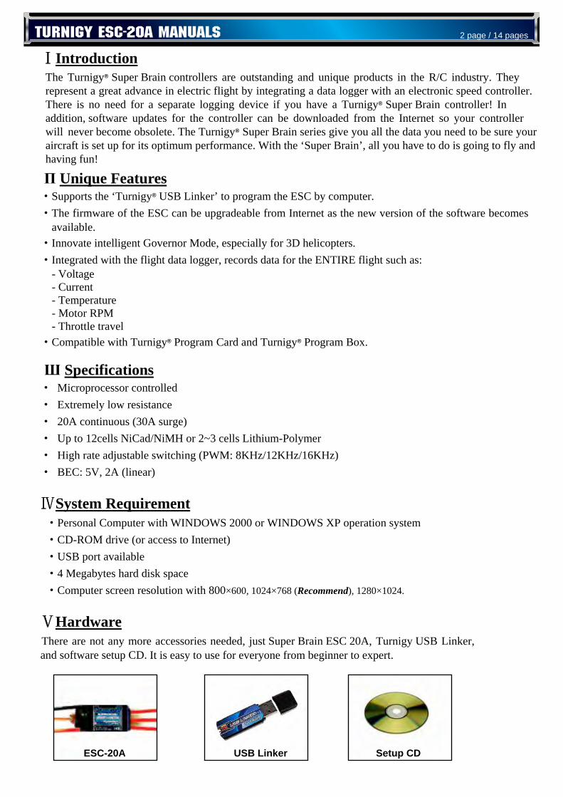
ⅤHardware There are not any more accessories needed, just Super Brain ESC 20A, Turnigy USB Linker,
It is easy to use for everyone from beginner to expert.
The Turnigy® Super Brain controllers are outstanding and unique products in the R/C industry. They represent a great advance in electric flight by integrating a data logger with an electronic speed controller. There is no need for a separate logging device if you have a Turnigy® Super Brain controller! In addition, software updates for the controller can be downloaded from the Internet so your controller will never become obsolete. The Turnigy® Super Brain series give you all the data you need to be sure your aircraft is set up for its optimum performance. With the ‘Super Brain’, all you have to do is going to fly and having fun!
TURNIGY ESC-20A MANUALS 2 page / 14 pages
USB Linker Setup CD ESC-20A
and software setup CD.
Ⅵ Using the ESC ·Calibrate the throttle range of transmitter at the first time to use the controller (Recommend)
- Correctly connect the ESC with brushless motor, plug the receiver lead of ESC into receiver ( usually into Channel 3); - Put the throttle to the highest position, turn on the transmitter; - Power on the receiver, ESC and motor. There are 3 beeps emitted from the motor, which indicates all electronics are correctly power on for the setting. - Then there are 4 long beeps emitted from the motor ♪ ♪ ♪ ♪ . - Move the throttle to the lowest position after each one beep of the four long beeps. - Waiting one second, there will be two beeps emitted from the motor - Calibration of throttle is completed.
·Program the ESC’ s settings or use the default setting (by Turnigy Program Card/ on PC/ by throttle stick)
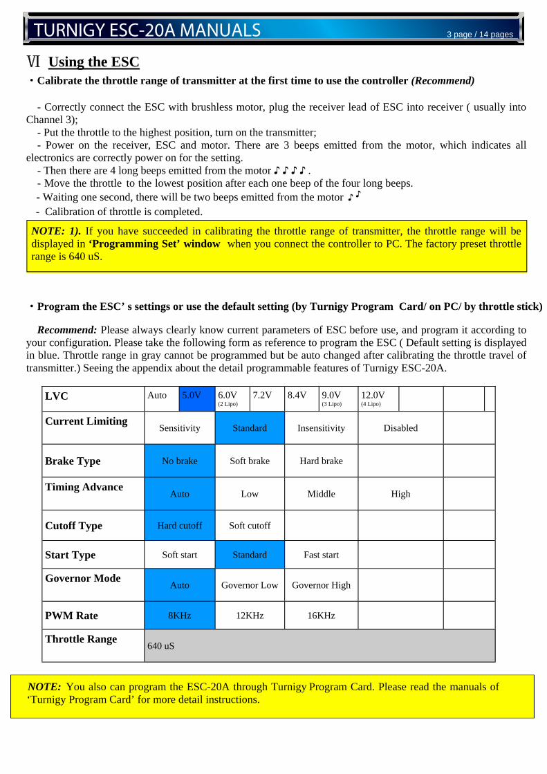
Recommend: Please always clearly know current parameters of ESC before use, and program it according to your configuration. Please take the following form as reference to program the ESC ( Default setting is displayed in blue. Throttle range in gray cannot be programmed but be auto changed after calibrating the throttle travel of transmitter.) Seeing the appendix about the detail programmable features of Turnigy ESC-20A.
♪
♪
NOTE: 1). If you have succeeded in calibrating the throttle range of transmitter, the throttle range will be displayed in ‘Programming Set’ window when you connect the controller to PC. The factory preset throttle range is 640 uS.
LVC Auto 5.0V 6.0V (2 Lipo)
7.2V 8.4V 9.0V (3 Lipo)
12.0V (4 Lipo)
Current Limiting Sensitivity Standard Insensitivity Disabled
Brake Type No brake Soft brake Hard brake
Timing Advance Auto Low Middle High
Cutoff Type Hard cutoff Soft cutoff
Start Type Soft start Standard Fast start
Governor Mode Auto Governor Low Governor High
PWM Rate 8KHz 12KHz 16KHz
Throttle Range 640 uS
NOTE: You also can program the ESC-20A through Turnigy Program Card. Please read the manuals of ‘Turnigy Program Card’ for more detail instructions.
TURNIGY ESC-20A MANUALS 3 page / 14 pages
·In order to well record the flight data and utilize the storage space of the logger, please set the ‘Recorder
Configuration’ in the menu of ‘Data Logger’ after installing ‘Turnigy Super Brain ESC’ soft. (see Ⅸ)
·When you finish the setting, repower the ESC, receiver and motor, there are two beeps emitted from the motor, then is ready to go fly and enjoy the flying.
Ⅶ Installing Turnigy Software
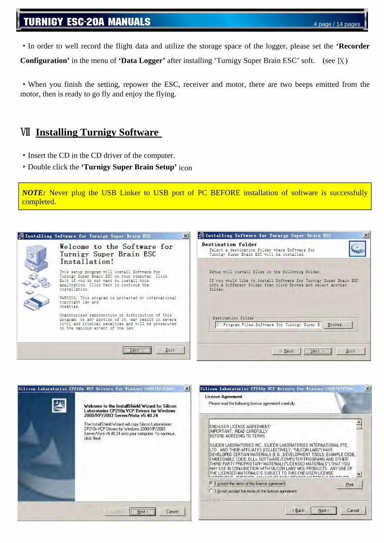
·Insert the CD in the CD driver of the computer. ·Double click the ‘Turnigy Super Brain Setup’ icon
NOTE: Never plug the USB Linker to USB port of PC BEFORE installation of software is successfully completed.
TURNIGY ESC-20A MANUALS 4 page / 14 pages
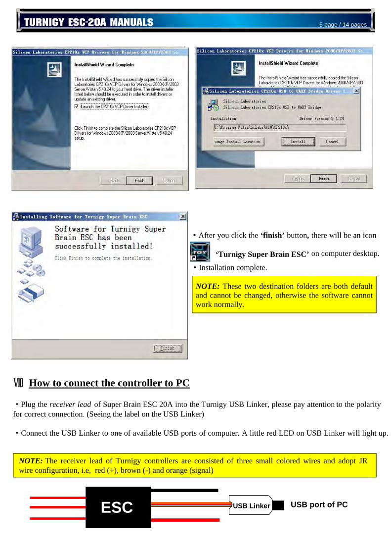
·After you click the ‘finish’ button, there will be an icon
‘Turnigy Super Brain ESC’ on computer desktop.
·Installation complete.
Ⅷ How to connect the controller to PC
·Plug the receiver lead of Super Brain ESC 20A into the Turnigy USB Linker, please pay attention to the polarityfor correct connection. (Seeing the label on the USB Linker)
·Connect the USB Linker to one of available USB ports of computer. A little red LED on USB Linker will light up.
NOTE: These two destination folders are both default and cannot be changed, otherwise the software cannot work normally.
ESC USB Linker USB port of PC
TURNIGY ESC-20A MANUALS 5 page / 14 pages
NOTE: The receiver lead of Turnigy controllers are consisted of three small colored wires and adopt JR wire configuration, i.e, red (+), brown (-) and orange (signal)
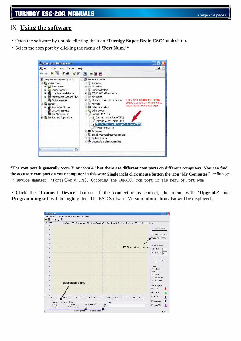
Ⅸ Using the software ·Open the software by double clicking the icon ‘Turnigy Super Brain ESC’ on desktop. ·Select the com port by clicking the menu of ‘Port Num.’*
*The com port is generally ‘com 3’ or ‘com 4,’ but there are different com ports on different computers. You can find the accurate com port on your computer in this way: Single right click mouse button the icon ‘My Computer ’→Manage
→ Device Manager →Ports(Com & LPT). Choosing the CORRECT com port in the menu of Port Num.
·Click the ‘Connect Device’ button. If the connection is correct, the menu with ‘Upgrade’ and ‘Programming set’ will be highlighted. The ESC Software Version information also will be displayed..
.
Data display area
TURNIGY ESC-20A MANUALS 6 page / 14 pages
If you have installed the Turnigy software correctly, the item will be displayed in Device Manager
ESC version number
Data display area
Centigrade Fahrenheit
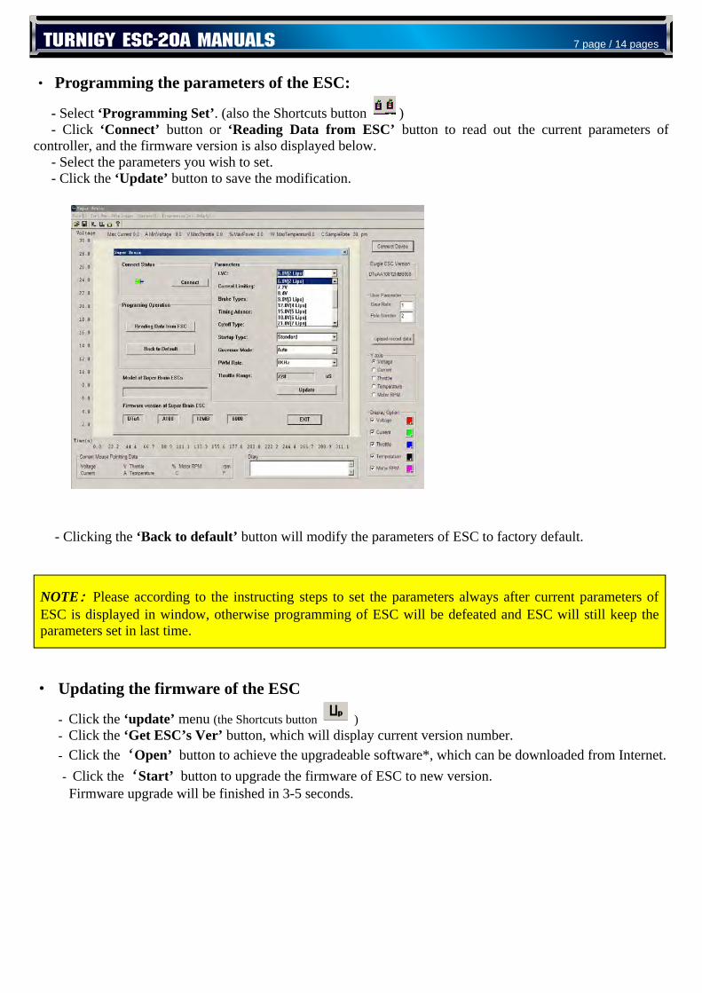
· Programming the parameters of the ESC:
- Select ‘Programming Set’. (also the Shortcuts button ) - Click ‘Connect’ button or ‘Reading Data from ESC’ button to read out the current parameters of controller, and the firmware version is also displayed below. - Select the parameters you wish to set. - Click the ‘Update’ button to save the modification. - Clicking the ‘Back to default’ button will modify the parameters of ESC to factory default.
· Updating the firmware of the ESC
- Click the ‘update’ menu (the Shortcuts button ) - Click the ‘Get ESC’s Ver’ button, which will display current version number. - Click the‘Open’ button to achieve the upgradeable software*, which can be downloaded from Internet. - Click the‘Start’ button to upgrade the firmware of ESC to new version. Firmware upgrade will be finished in 3-5 seconds.
NOTE: Please according to the instructing steps to set the parameters always after current parameters of ESC is displayed in window, otherwise programming of ESC will be defeated and ESC will still keep the parameters set in last time.
TURNIGY ESC-20A MANUALS 7 page / 14 pages
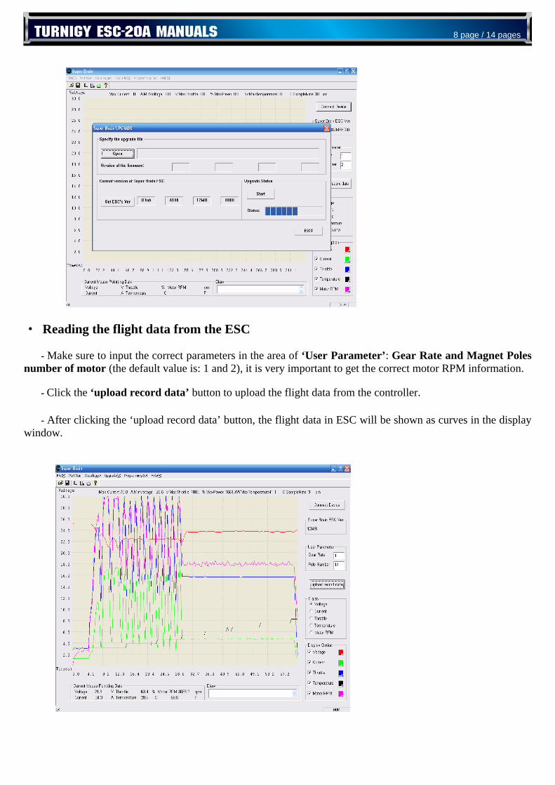
· Reading the flight data from the ESC - Make sure to input the correct parameters in the area of ‘User Parameter’: Gear Rate and Magnet Poles number of motor (the default value is: 1 and 2), it is very important to get the correct motor RPM information. - Click the ‘upload record data’ button to upload the flight data from the controller.
- After clicking the ‘upload record data’ button, the flight data in ESC will be shown as curves in the display window.
TURNIGY ESC-20A MANUALS 8 page / 14 pages
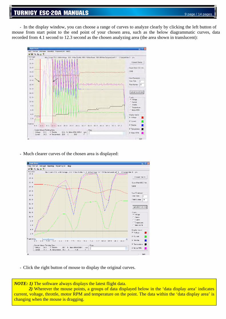
- In the display window, you can choose a range of curves to analyze clearly by clicking the left button of mouse from start point to the end point of your chosen area, such as the below diagrammatic curves, data recorded from 4.1 second to 12.3 second as the chosen analyzing area (the area shown in translucent): - Much clearer curves of the chosen area is displayed: - Click the right button of mouse to display the original curves.
NOTE: 1) The software always displays the latest flight data. 2) Wherever the mouse points, a groups of data displayed below in the ‘data display area’ indicates current, voltage, throttle, motor RPM and temperature on the point. The data within the ‘data display area’ is changing when the mouse is dragging.
TURNIGY ESC-20A MANUALS 9 page / 14 pages
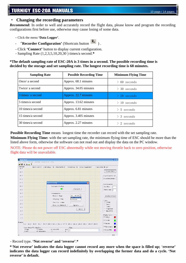
· Changing the recording parameters Recommend: In order to well and accurately record the flight data, please know and program the recording configurations first before use, otherwise may cause losing of some data. - Click the menu ‘Data Logger’.
- ‘Recorder Configuration’ (Shortcuts button ) . - Click ‘Connect’ button to display current configuration. - Sampling Rate (1,2,3,5,10,20,30 ) times/a second.*
*The default sampling rate of ESC-20A is 3 times in a second. The possible recording time is decided by the storage and set sampling rate. The longest recording time is 68 minutes. Possible Recording Time means longest time the recorder can record with the set sampling rate. Minimum Flying Time: with the set sampling rate, the minimum flying time of ESC should be more than the listed above form, otherwise the software can not read out and display the data on the PC window.
- Record type. ‘Not reverse’ and ‘reverse’.* *‘Not reverse’ indicates the data logger cannot record any more when the space is filled up; ‘reverse’ indicates the data logger can record indefinitely by overlapping the former data and do a cycle. ‘Not reverse’ is default.
Sampling Rate Possible Recording Time Minimum Flying Time
Once/ a second Approx. 68.1 minutes > 60 seconds
Twice/ a second Approx. 34.05 minutes > 30 seconds
3 times/ a second Approx. 22.7 minutes > 20 seconds
5 times/a second Approx. 13.62 minutes > 10 seconds
10 times/a second Approx. 6.81 minutes > 5 seconds
15 times/a second Approx. 3.405 minutes > 3 seconds
30 times/a second Approx. 2.27 minutes > 2 seconds
TURNIGY ESC-20A MANUALS 10 page / 14 pages
NOTE: Please do not power off ESC abnormally while not moving throttle back to zero position, otherwise flight data will be unavailable.
- ‘Cur fly times’ button is never highlighted.* *‘Cur fly times’ button records the times you have flown. The ESC can record most 16 times flying. You can clear it by clicking the ‘Clear Logger Data’ button. ESC be powered is calculated as once.
- Select the configuration you wish to set, and click ‘Update’ to save modifications.
- Click the button ‘Clear Logger Data’ to clear the data in the ESC for enough space to record for the next flying.
Recommend to always clear all data before next flying and to save the useful data as a file on PC before clearing.
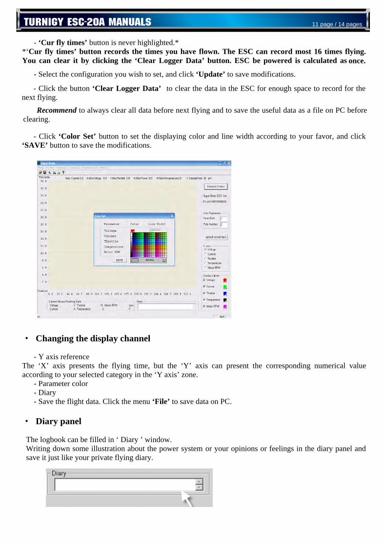
- Click ‘Color Set’ button to set the displaying color and line width according to your favor, and click ‘SAVE’ button to save the modifications.
· Changing the display channel - Y axis reference The ‘X’ axis presents the flying time, but the ‘Y’ axis can present the corresponding numerical value according to your selected category in the ‘Y axis’ zone. - Parameter color - Diary - Save the flight data. Click the menu ‘File’ to save data on PC.
· Diary panel
The logbook can be filled in ‘ Diary ’ window. Writing down some illustration about the power system or your opinions or feelings in the diary panel and save it just like your private flying diary.
TURNIGY ESC-20A MANUALS 11 page / 14 pages
Appendix
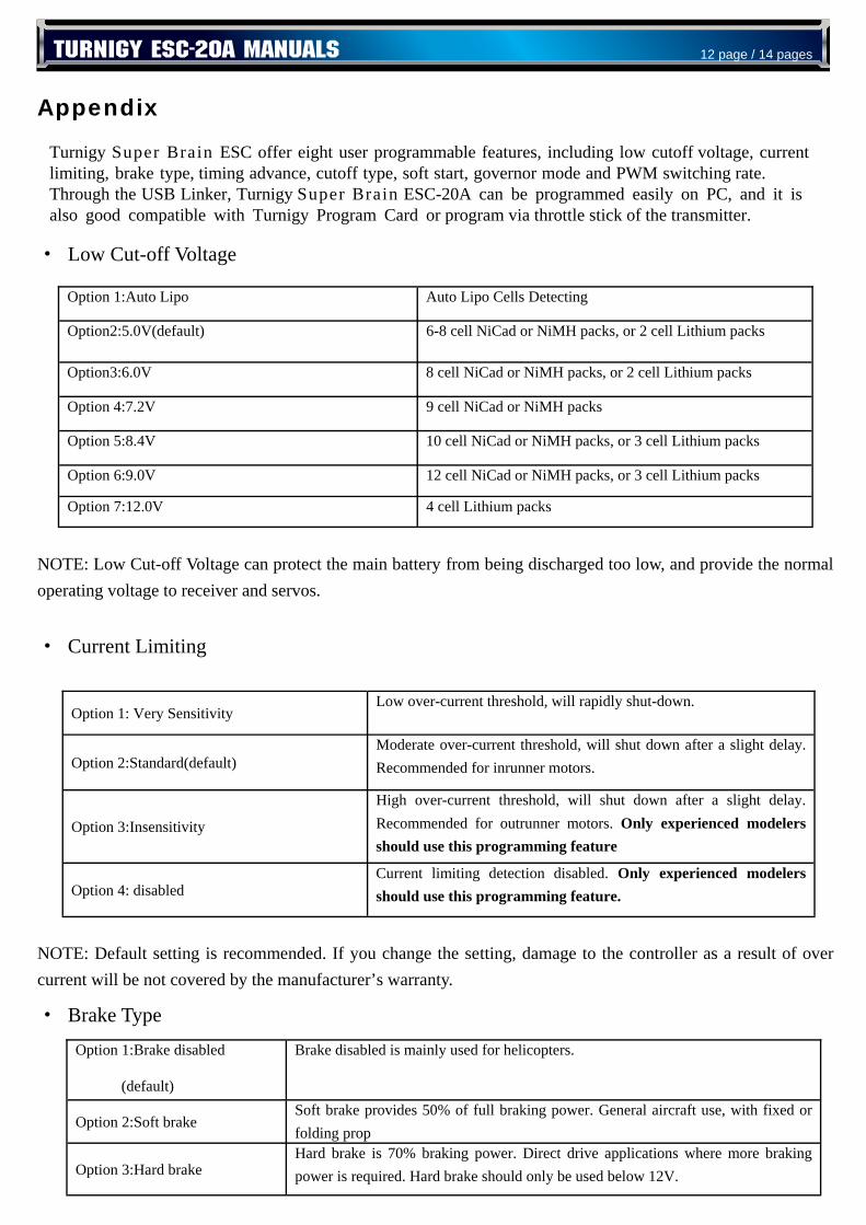
· Low Cut-off Voltage
NOTE: Low Cut-off Voltage can protect the main battery from being discharged too low, and provide the normal operating voltage to receiver and servos.
· Current Limiting
NOTE: Default setting is recommended. If you change the setting, damage to the controller as a result of over current will be not covered by the manufacturer’s warranty.
· Brake Type
Option 1: Very Sensitivity Low over-current threshold, will rapidly shut-down.
Option 2:Standard(default) Moderate over-current threshold, will shut down after a slight delay. Recommended for inrunner motors.
Option 3:Insensitivity
High over-current threshold, will shut down after a slight delay. Recommended for outrunner motors. Only experienced modelers should use this programming feature
Option 4: disabled Current limiting detection disabled. Only experienced modelers should use this programming feature.
Option 1:Brake disabled
(default)
Brake disabled is mainly used for helicopters.
Option 2:Soft brake Soft brake provides 50% of full braking power. General aircraft use, with fixed or folding prop
Option 3:Hard brake Hard brake is 70% braking power. Direct drive applications where more braking power is required. Hard brake should only be used below 12V.
gnitceteD slleC opiL otuA opiL otuA:1 noitpO
skcap muihtiL llec 2 ro ,skcap HMiN ro daCiN llec 8-6 )tluafed(V0.5:2noitpO
skcap muihtiL llec 2 ro ,skcap HMiN ro daCiN llec 8 V0.6:3noitpO
skcap HMiN ro daCiN llec 9 V2.7:4 noitpO
skcap muihtiL llec 3 ro ,skcap HMiN ro daCiN llec 01 V4.8:5 noitpO
skcap muihtiL llec 3 ro ,skcap HMiN ro daCiN llec 21 V0.9:6 noitpO
skcap muihtiL llec 4 V0.21:7 noitpO
TURNIGY ESC-20A MANUALS 12 page / 14 pages
Turnigy Super Brain ESC offer eight user programmable features, including low cutoff voltage, current limiting, brake type, timing advance, cutoff type, soft start, governor mode and PWM switching rate. Through the USB Linker, Turnigy Super Brain ESC-20A can be programmed easily on PC, and it is also good compatible with Turnigy Program Card or program via throttle stick of the transmitter.
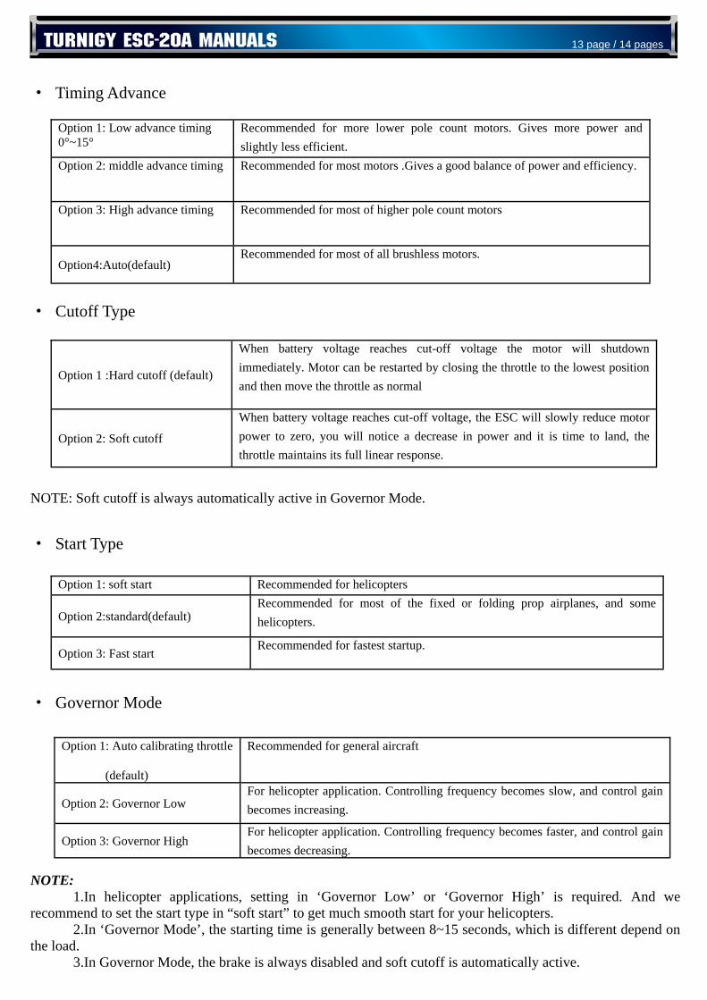
· Timing Advance · Cutoff Type NOTE: Soft cutoff is always automatically active in Governor Mode.
· Start Type
· Governor Mode
NOTE: 1.In helicopter applications, setting in ‘Governor Low’ or ‘Governor High’ is required. And we recommend to set the start type in “soft start” to get much smooth start for your helicopters. 2.In ‘Governor Mode’, the starting time is generally between 8~15 seconds, which is different depend on the load. 3.In Governor Mode, the brake is always disabled and soft cutoff is automatically active.
Option 1: Low advance timing 0°~15°
Recommended for more lower pole count motors. Gives more power and slightly less efficient.
Option 2: middle advance timing Recommended for most motors .Gives a good balance of power and efficiency.
Option 3: High advance timing Recommended for most of higher pole count motors
Option4:Auto(default) Recommended for most of all brushless motors.
Option 1 :Hard cutoff (default)
When battery voltage reaches cut-off voltage the motor will shutdown immediately. Motor can be restarted by closing the throttle to the lowest position and then move the throttle as normal
Option 2: Soft cutoff
When battery voltage reaches cut-off voltage, the ESC will slowly reduce motor power to zero, you will notice a decrease in power and it is time to land, the throttle maintains its full linear response.
Option 1: soft start Recommended for helicopters
Option 2:standard(default) Recommended for most of the fixed or folding prop airplanes, and some helicopters.
Option 3: Fast start Recommended for fastest startup.
Option 1: Auto calibrating throttle
(default)
Recommended for general aircraft
Option 2: Governor Low For helicopter application. Controlling frequency becomes slow, and control gain becomes increasing.
Option 3: Governor High For helicopter application. Controlling frequency becomes faster, and control gain becomes decreasing.
TURNIGY ESC-20A MANUALS 13 page / 14 pages

TURNIGY ESC-20A MANUALS 14 page / 14 pages
· PWM Switching Rate Note: we strongly recommend only the experienced modeler could change this setting.
Ⅹ
Option 1:8KHz(default) Recommended for most brushless motors
Option 2: 12KHz Recommended for low inductance motors
Option 3: 16KHz Recommended for very low inductance motors
Products Voltage Current/Surge BEC Dimension (mm) Weight (with cables)
Turnigy ESC 20A 2~3S Lipo 20/30amp 2amp (Linear) 55×27×12 23g
Turnigy ESC 40A 2-3S Lipo 40/50amp 2amp (Linear) 55×27×12 25g
Turnigy ESC 60A 2-6S Lipo 60/70amp 4amp (Switching) 71×26.5×15 50g
Turnigy ESC 80A 2-6S Lipo 80/90amp 4amp (Switching) 71×26.5×15 52g
Turnigy ESC 100A 4-12S Lipo 100/120amp no (OPTO) 69×52×24 109g
Turnigy USB Linker Connector for Turnigy speed controllers to PC 6g
All models of Turnigy Super Brain-series controllers