Embed Size (px)
Citation preview
Super 80 Professional
Aircraft Operating Manual
By Coolsky, 2018 Version 2.0
Super 80 Professional – AOM TABLE OF CONTENTS
Super 80 Professional – Aircraft Operating Manual
Coolsky, 2018
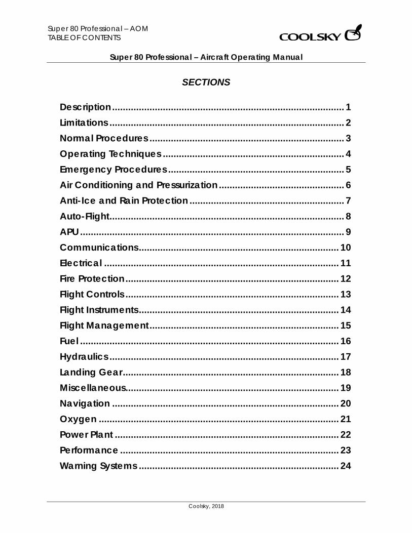
SECTIONS
Description ....................................................................................... 1 Limitations ........................................................................................ 2 Normal Procedures ......................................................................... 3 Operating Techniques .................................................................... 4 Emergency Procedures .................................................................. 5 Air Conditioning and Pressurization ............................................... 6 Anti-Ice and Rain Protection .......................................................... 7 Auto-Flight ........................................................................................ 8 APU ................................................................................................... 9 Communications ........................................................................... 10 Electrical ........................................................................................ 11 Fire Protection ................................................................................ 12 Flight Controls ................................................................................ 13 Flight Instruments ........................................................................... 14 Flight Management ....................................................................... 15 Fuel ................................................................................................. 16 Hydraulics ...................................................................................... 17 Landing Gear ................................................................................. 18 Miscellaneous ................................................................................ 19 Navigation ..................................................................................... 20 Oxygen .......................................................................................... 21 Power Plant .................................................................................... 22 Performance .................................................................................. 23 Warning Systems ........................................................................... 24
Super 80 Professional – AOM TABLE OF CONTENTS
Super 80 Professional – Aircraft Operating Manual
Coolsky, 2018
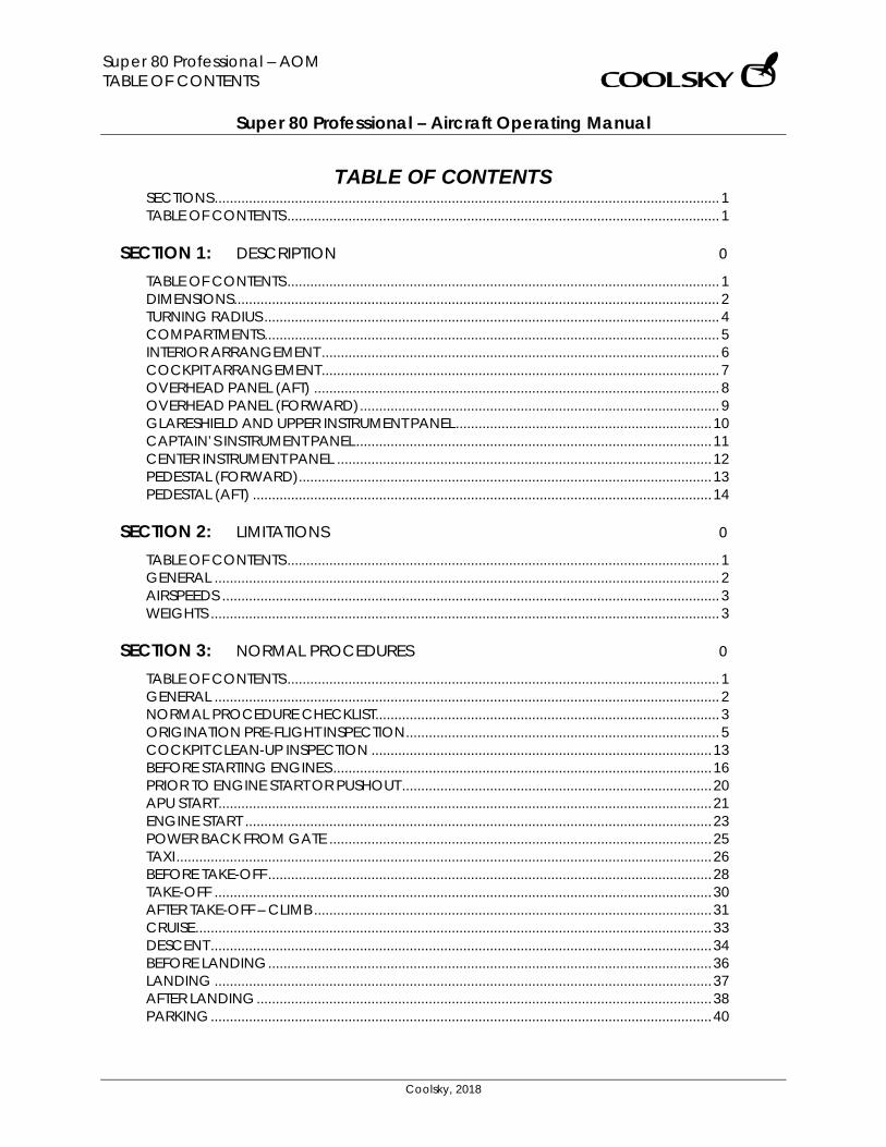
TABLE OF CONTENTS SECTIONS .................................................................................................................................... 1 TABLE OF CONTENTS ................................................................................................................. 1
SECTION 1: DESCRIPTION 0
TABLE OF CONTENTS ................................................................................................................. 1 DIMENSIONS ............................................................................................................................... 2 TURNING RADIUS ....................................................................................................................... 4 COMPARTMENTS ....................................................................................................................... 5 INTERIOR ARRANGEMENT ........................................................................................................ 6 COCKPIT ARRANGEMENT ........................................................................................................ 7 OVERHEAD PANEL (AFT) .......................................................................................................... 8 OVERHEAD PANEL (FORWARD) .............................................................................................. 9 GLARESHIELD AND UPPER INSTRUMENT PANEL ................................................................... 10 CAPTAIN’S INSTRUMENT PANEL ............................................................................................. 11 CENTER INSTRUMENT PANEL .................................................................................................. 12 PEDESTAL (FORWARD) ............................................................................................................ 13 PEDESTAL (AFT) ........................................................................................................................ 14
SECTION 2: LIMITATIONS 0
TABLE OF CONTENTS ................................................................................................................. 1 GENERAL .................................................................................................................................... 2 AIRSPEEDS .................................................................................................................................. 3 WEIGHTS ..................................................................................................................................... 3
SECTION 3: NORMAL PROCEDURES 0
TABLE OF CONTENTS ................................................................................................................. 1 GENERAL .................................................................................................................................... 2 NORMAL PROCEDURE CHECKLIST.......................................................................................... 3 ORIGINATION PRE-FLIGHT INSPECTION .................................................................................. 5 COCKPIT CLEAN-UP INSPECTION ......................................................................................... 13 BEFORE STARTING ENGINES ................................................................................................... 16 PRIOR TO ENGINE START OR PUSHOUT ................................................................................. 20 APU START ................................................................................................................................. 21 ENGINE START .......................................................................................................................... 23 POWER BACK FROM GATE .................................................................................................... 25 TAXI ............................................................................................................................................ 26 BEFORE TAKE-OFF .................................................................................................................... 28 TAKE-OFF .................................................................................................................................. 30 AFTER TAKE-OFF – CLIMB ........................................................................................................ 31 CRUISE ....................................................................................................................................... 33 DESCENT ................................................................................................................................... 34 BEFORE LANDING .................................................................................................................... 36 LANDING .................................................................................................................................. 37 AFTER LANDING ....................................................................................................................... 38 PARKING ................................................................................................................................... 40
Super 80 Professional – AOM TABLE OF CONTENTS
Super 80 Professional – Aircraft Operating Manual
Coolsky, 2018
SECTION 4: OPERATING TECHNIQUES 0
TABLE OF CONTENTS ................................................................................................................. 1 PREFACE ..................................................................................................................................... 2 TAXI .............................................................................................................................................. 2 JET BLAST ..................................................................................................................................... 3 TAKE-OFF .................................................................................................................................... 4 CLIMB .......................................................................................................................................... 4 CRUISE ......................................................................................................................................... 5 DESCENT ..................................................................................................................................... 5 HOLDING .................................................................................................................................... 6 APPROACH AND LANDING ..................................................................................................... 7
SECTION 5: EMERGENCY PROCEDURES 0
SECTION 6: AIR CONDITIONING AND PRESSURIZATION 0
TABLE OF CONTENTS ................................................................................................................. 1 GENERAL .................................................................................................................................... 2 FUNCTIONAL SCHEMATIC - PNEUMATICS .............................................................................. 3 CONTROLS AND INDICATORS ................................................................................................. 4 AIR CONDITIONING .................................................................................................................. 5 PRESSURIZATION ........................................................................................................................ 7 WARNING AND CAUTION INDICATORS ................................................................................. 9
SECTION 7: ANTI-ICE AND RAIN PROTECTION 0
TABLE OF CONTENTS ................................................................................................................. 1 GENERAL .................................................................................................................................... 2 CONTROLS AND INDICATORS ................................................................................................. 3 WARNING AND CAUTION INDICATORS ................................................................................. 5
SECTION 8: AUTO-FLIGHT 0
TABLE OF CONTENTS ................................................................................................................. 1 GENERAL .................................................................................................................................... 2 FLIGHT DIRECTOR ...................................................................................................................... 5 AUTOTHROTTLE .......................................................................................................................... 6 ROLL MODE SELECTORS ........................................................................................................... 7 PITCH MODE SELECTORS .......................................................................................................... 8 YAW DAMPER, MACH TRIM AND ALTITUDE ADVISORY LIGHT........................................... 10 EFIS CONTROLS ........................................................................................................................ 11 FLIGHT MODE ANNUNCIATOR .............................................................................................. 12 FMA – LEGEND LIGHTS ............................................................................................................ 13 FMA – AUTOTHROTTLE WINDOW ........................................................................................... 14 FMA – ARM WINDOW ............................................................................................................. 16 FMA – ROLL WINDOW ............................................................................................................. 17 FMA – PITCH WINDOW ........................................................................................................... 19
Super 80 Professional – AOM TABLE OF CONTENTS
Super 80 Professional – Aircraft Operating Manual
Coolsky, 2018
SECTION 9: APU 0
TABLE OF CONTENTS ................................................................................................................. 1 GENERAL .................................................................................................................................... 2 CONTROLS AND INDICATORS ................................................................................................. 3
SECTION 10: COMMUNICATIONS 0
TABLE OF CONTENTS ................................................................................................................. 1 GENERAL .................................................................................................................................... 2 CONTROLS AND INDICATORS ................................................................................................. 3
SECTION 11: ELECTRICAL 0
TABLE OF CONTENTS ................................................................................................................. 1 GENERAL .................................................................................................................................... 2 CONTROLS AND INDICATORS ................................................................................................. 4 WARNING AND CAUTION INDICATORS ................................................................................. 7
SECTION 12: FIRE PROTECTION 0
TABLE OF CONTENTS ................................................................................................................. 1 GENERAL .................................................................................................................................... 2 CONTROLS AND INDICATORS ................................................................................................. 3
SECTION 13: FLIGHT CONTROLS 0
TABLE OF CONTENTS ................................................................................................................. 1 GENERAL .................................................................................................................................... 2 MAJOR COMPONENT LOCATION .......................................................................................... 7 LONGITUDINAL CONTROL AND TRIM ..................................................................................... 8 RUDDER CONTROL AND TRIM ............................................................................................... 11 SPEEDBRAKE/SPOILER ............................................................................................................. 12 FLAP/SLAT SYSTEM ................................................................................................................... 13 MACH TRIM AND STALL WARNING ....................................................................................... 14 WARNING AND CAUTION INDICATORS ............................................................................... 15
Super 80 Professional – AOM TABLE OF CONTENTS
Super 80 Professional – Aircraft Operating Manual
Coolsky, 2018
SECTION 14: FLIGHT INSTRUMENTS 0
TABLE OF CONTENTS ................................................................................................................. 1 GENERAL .................................................................................................................................... 2 AIRSPEED/MACH INDICATOR.................................................................................................. 4 CADC AND STATIC AIR SWITCHING ....................................................................................... 5 TAS/SAT INDICATOR .................................................................................................................. 6 ALTIMETER ................................................................................................................................... 7 RADIO ALTIMETER ...................................................................................................................... 8 SLIP INDICATOR ......................................................................................................................... 8 STANDBY INSTRUMENTS AND CLOCK ..................................................................................... 9 VERTICAL SPEED INDICATOR ................................................................................................. 10 PRIMARY FLIGHT DISPLAY ....................................................................................................... 11 PFD FAIL LEGENDS ................................................................................................................... 13 PFD COMPACTED MODE ....................................................................................................... 14
SECTION 15: FLIGHT MANAGEMENT 0
TABLE OF CONTENTS ................................................................................................................. 1 GENERAL .................................................................................................................................... 2 IRS MODE SELECT PANEL .......................................................................................................... 6 FMS FLIGHT GUIDANCE MODES .............................................................................................. 7 MCDU PAGE DESCRIPTION .................................................................................................... 11 FMS OPERATIONS .................................................................................................................... 40
SECTION 16: FUEL 0
TABLE OF CONTENTS ................................................................................................................. 1 GENERAL .................................................................................................................................... 2 CONTROLS AND INDICATORS ................................................................................................. 3 WARNING AND CAUTION INDICATORS ................................................................................. 6 FUEL DISTRIBUTION GUIDE......................................................................................................... 7
SECTION 17: HYDRAULICS 0
TABLE OF CONTENTS ................................................................................................................. 1 GENERAL .................................................................................................................................... 2 CONTROLS AND INDICATORS ................................................................................................. 3 WARNING AND CAUTION INDICATORS ................................................................................. 4
SECTION 18: LANDING GEAR 0
TABLE OF CONTENTS ................................................................................................................. 1 GENERAL .................................................................................................................................... 2 CONTROLS AND INDICATORS ................................................................................................. 5 WARNING AND CAUTION INDICATORS ................................................................................. 9
Super 80 Professional – AOM TABLE OF CONTENTS
Super 80 Professional – Aircraft Operating Manual
Coolsky, 2018
SECTION 19: MISCELLANEOUS 0
TABLE OF CONTENTS ................................................................................................................. 1 EXTERIOR LIGHTING ................................................................................................................... 2 COCKPIT LIGHTING ................................................................................................................... 3 VOICE RECORDER .................................................................................................................... 5 ELECTRONIC OVERHEAD ANNUNCIATON PANEL (EOAP) .................................................. 6
SECTION 20: NAVIGATION 0
TABLE OF CONTENTS ................................................................................................................. 1 GENERAL .................................................................................................................................... 2 VHF NAV CONTROL PANEL AND ADF CONTROL PANEL ..................................................... 3 RADIO DISTANCE MAGNETIC INDICATOR (RDMI) ............................................................... 4 NAVIGATION DISPLAY (ROSE MODE) .................................................................................... 5 NAVIGATION DISPLAY (ARC MODE) ...................................................................................... 6 NAVIGATION DISPLAY (MAP MODE) ..................................................................................... 8 NAVIGATION DISPLAY (PLAN MODE) .................................................................................... 9 MODE SELECTOR CONTROL PANEL & MAG/TRUE LIGHT .................................................. 10
SECTION 21: OXYGEN 0
TABLE OF CONTENTS ................................................................................................................. 1 GENERAL .................................................................................................................................... 2 CONTROLS AND INDICATORS ................................................................................................. 3
SECTION 22: POWER PLANT 0
TABLE OF CONTENTS ................................................................................................................. 1 GENERAL .................................................................................................................................... 2 CONTROLS AND INDICATORS ................................................................................................. 5 WARNING AND CAUTION INDICATORS ............................................................................... 11
SECTION 23: PERFORMANCE 0
TABLE OF CONTENTS ................................................................................................................. 1 GENERAL .................................................................................................................................... 2 TAKE-OFF .................................................................................................................................... 4 CLIMB ........................................................................................................................................ 10 CRUISE ....................................................................................................................................... 12 ARRIVAL .................................................................................................................................... 21 MISCELLANEOUS ..................................................................................................................... 25
SECTION 24: WARNING SYSTEMS 0
TABLE OF CONTENTS ................................................................................................................. 1 RADAR ........................................................................................................................................ 2 GROUND PROXIMITY WARNING SYSTEM ............................................................................... 5 WARNING AND CAUTION INDICATORS ................................................................................. 9 TCAS/VSI ................................................................................................................................... 10
Super 80 Professional – AOM DESCRIPTION Section 1 Page 0
Super 80 Professional – Aircraft Operating Manual
Coolsky, 2018
SECTION 1
DESCRIPTION
Super 80 Professional – AOM DESCRIPTION Section 1 Page 1
Super 80 Professional – Aircraft Operating Manual
Coolsky, 2018
TABLE OF CONTENTS
SECTION 1: DESCRIPTION 0
TABLE OF CONTENTS ................................................................................................................. 1 DIMENSIONS ............................................................................................................................... 2 TURNING RADIUS ....................................................................................................................... 4 COMPARTMENTS ....................................................................................................................... 5 INTERIOR ARRANGEMENT ........................................................................................................ 6 COCKPIT ARRANGEMENT ........................................................................................................ 7 OVERHEAD PANEL (AFT) .......................................................................................................... 8 OVERHEAD PANEL (FORWARD) .............................................................................................. 9 GLARESHIELD AND UPPER INSTRUMENT PANEL ................................................................... 10 CAPTAIN’S INSTRUMENT PANEL ............................................................................................. 11 CENTER INSTRUMENT PANEL .................................................................................................. 12 PEDESTAL (FORWARD) ............................................................................................................ 13 PEDESTAL (AFT) ........................................................................................................................ 14
Super 80 Professional – AOM DESCRIPTION Section 1 Page 2
Super 80 Professional – Aircraft Operating Manual
Coolsky, 2018
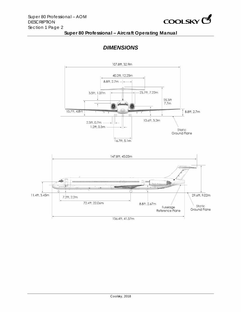
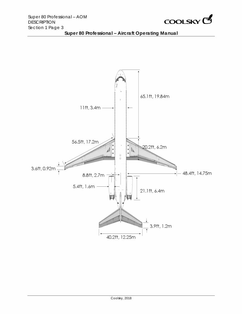
DIMENSIONS
Super 80 Professional – AOM DESCRIPTION Section 1 Page 3
Super 80 Professional – Aircraft Operating Manual
Coolsky, 2018
Super 80 Professional – AOM DESCRIPTION Section 1 Page 4
Super 80 Professional – Aircraft Operating Manual
Coolsky, 2018
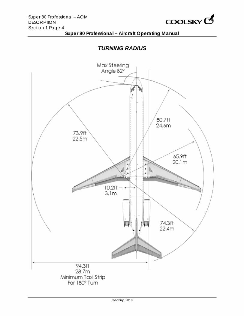
TURNING RADIUS
Super 80 Professional – AOM DESCRIPTION Section 1 Page 5
Super 80 Professional – Aircraft Operating Manual
Coolsky, 2018
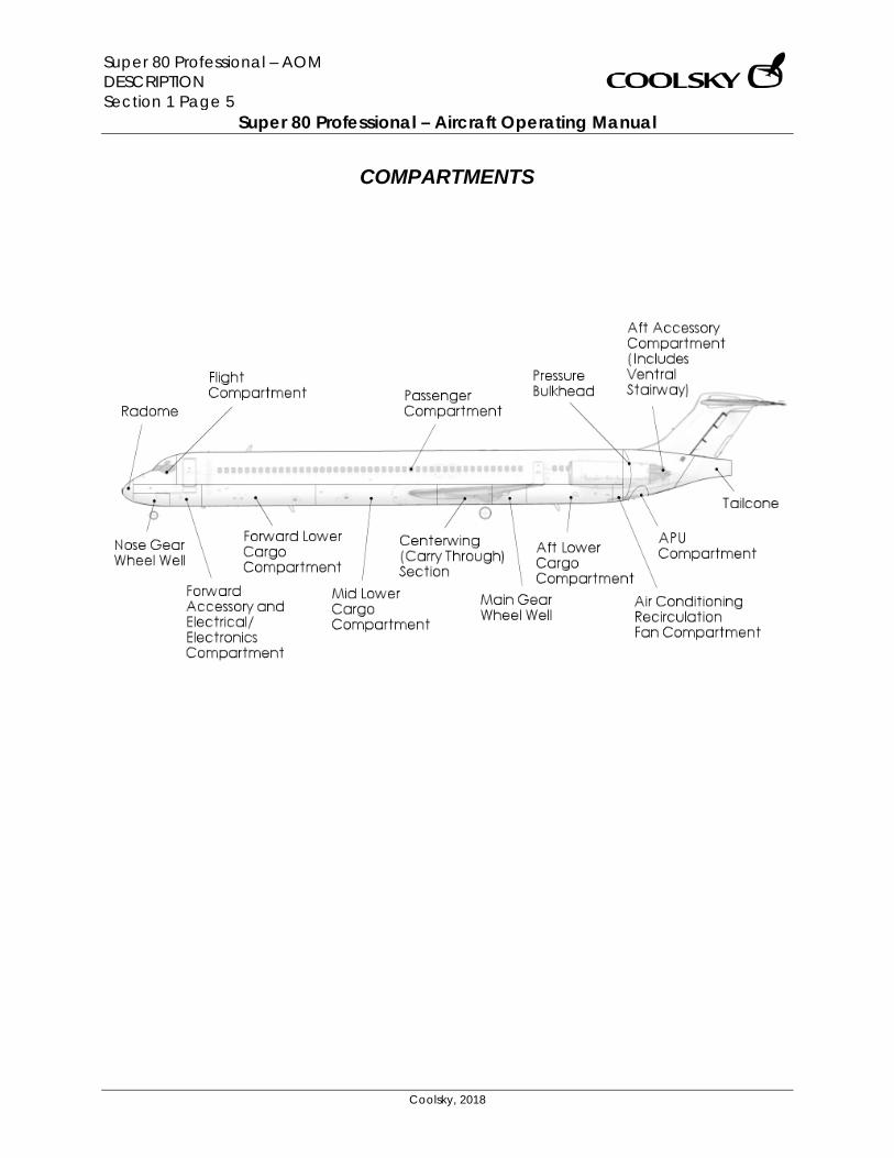
COMPARTMENTS
Super 80 Professional – AOM DESCRIPTION Section 1 Page 6
Super 80 Professional – Aircraft Operating Manual
Coolsky, 2018
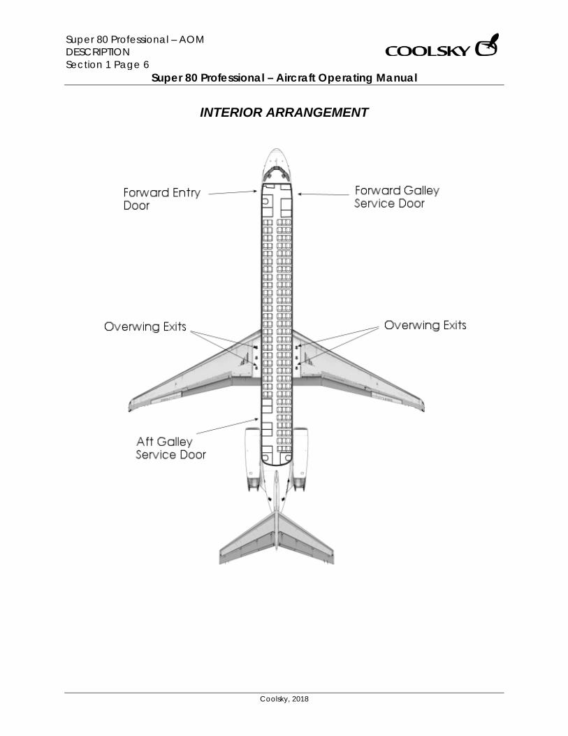
INTERIOR ARRANGEMENT
Super 80 Professional – AOM DESCRIPTION Section 1 Page 7
Super 80 Professional – Aircraft Operating Manual
Coolsky, 2018
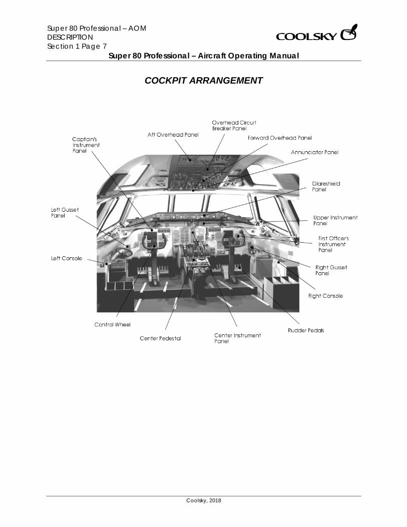
COCKPIT ARRANGEMENT
Super 80 Professional – AOM DESCRIPTION Section 1 Page 8
Super 80 Professional – Aircraft Operating Manual
Coolsky, 2018
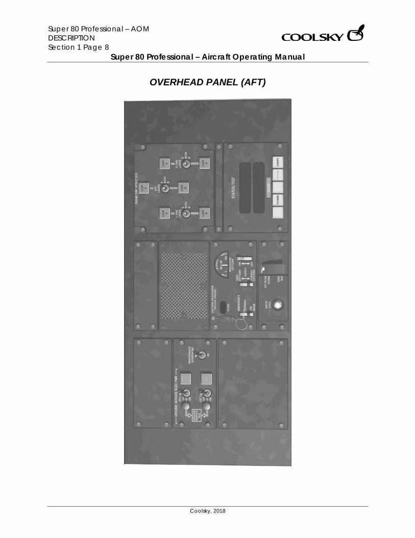
OVERHEAD PANEL (AFT)
Super 80 Professional – AOM DESCRIPTION Section 1 Page 9
Super 80 Professional – Aircraft Operating Manual
Coolsky, 2018
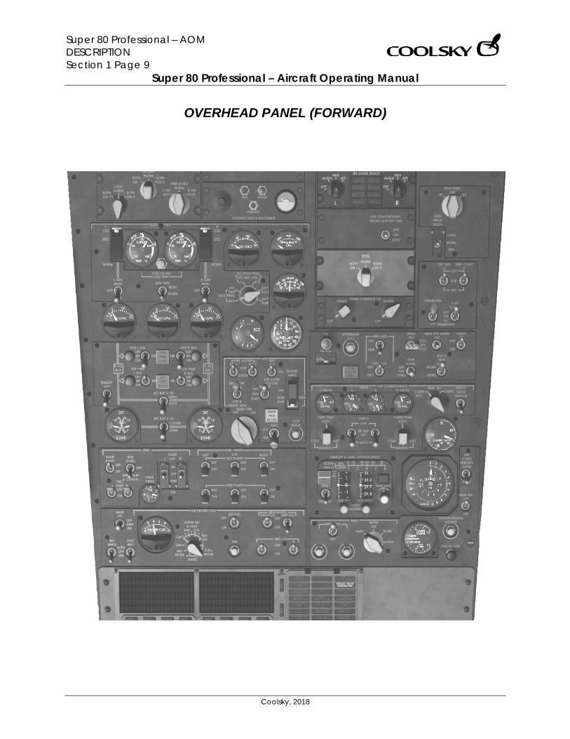
OVERHEAD PANEL (FORWARD)
Super 80 Professional – AOM DESCRIPTION Section 1 Page 10
Super 80 Professional – Aircraft Operating Manual
Coolsky, 2018
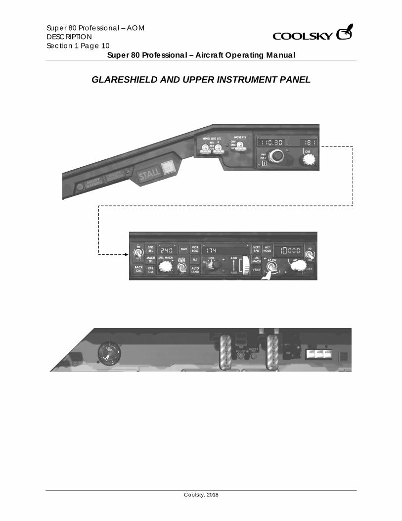
GLARESHIELD AND UPPER INSTRUMENT PANEL
Super 80 Professional – AOM DESCRIPTION Section 1 Page 11
Super 80 Professional – Aircraft Operating Manual
Coolsky, 2018
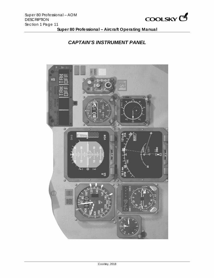
CAPTAIN’S INSTRUMENT PANEL
Super 80 Professional – AOM DESCRIPTION Section 1 Page 12
Super 80 Professional – Aircraft Operating Manual
Coolsky, 2018
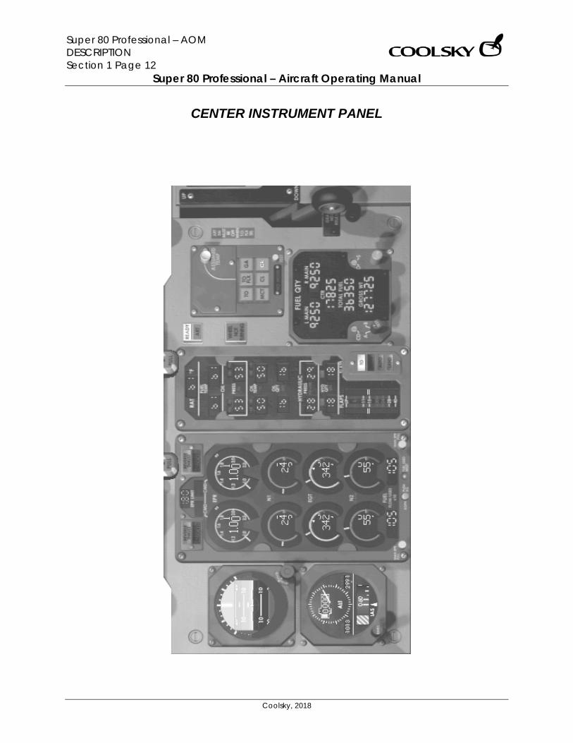
CENTER INSTRUMENT PANEL
Super 80 Professional – AOM DESCRIPTION Section 1 Page 13
Super 80 Professional – Aircraft Operating Manual
Coolsky, 2018
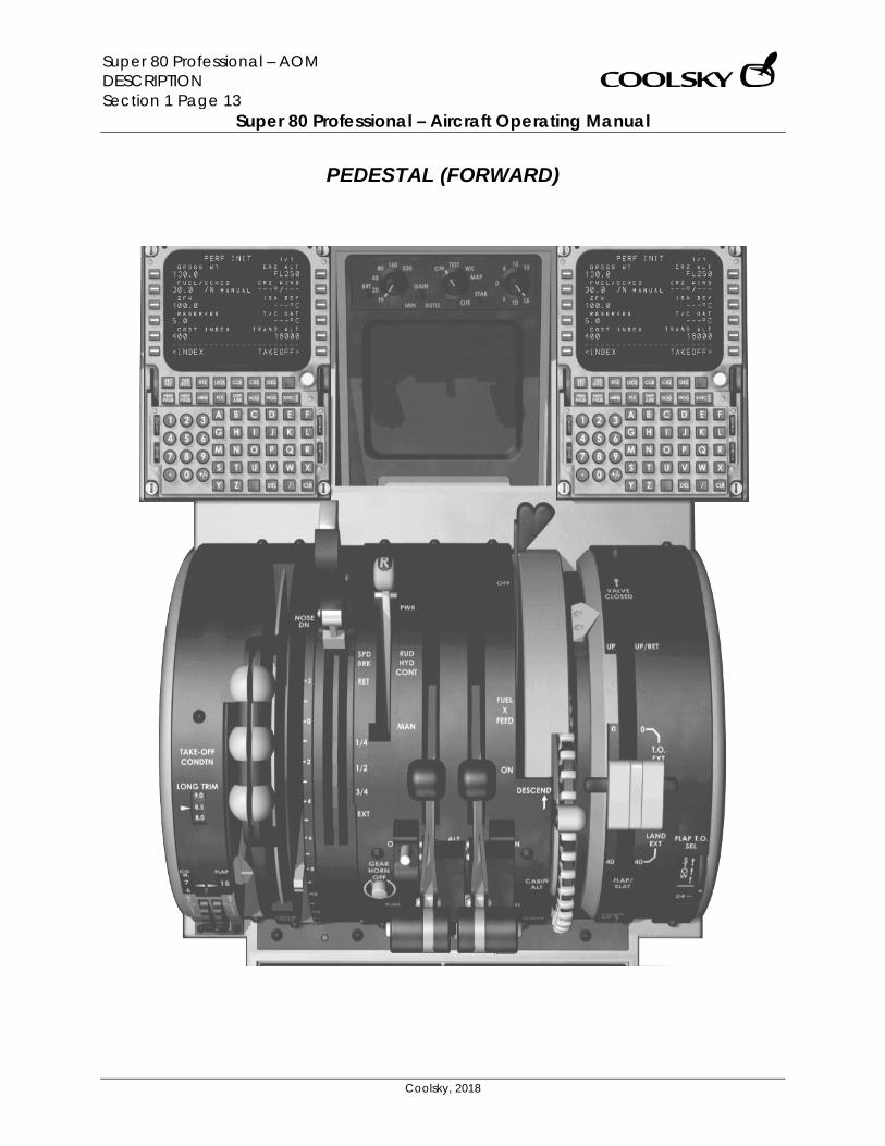
PEDESTAL (FORWARD)
Super 80 Professional – AOM DESCRIPTION Section 1 Page 14
Super 80 Professional – Aircraft Operating Manual
Coolsky, 2018
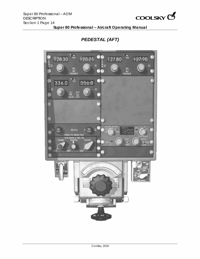
PEDESTAL (AFT)
Super 80 Professional – AOM LIMITATIONS Section 2 Page 0
Super 80 Professional – Aircraft Operating Manual
Coolsky, 2018
SECTION 2
LIMITATIONS

Super 80 Professional – AOM LIMITATIONS Section 2 Page 1
Super 80 Professional – Aircraft Operating Manual
Coolsky, 2018
TABLE OF CONTENTS
SECTION 2: LIMITATIONS 0
TABLE OF CONTENTS ................................................................................................................. 1 GENERAL .................................................................................................................................... 2 AIRSPEEDS .................................................................................................................................. 3 WEIGHTS ..................................................................................................................................... 3
Super 80 Professional – AOM LIMITATIONS Section 2 Page 2
Super 80 Professional – Aircraft Operating Manual
Coolsky, 2018
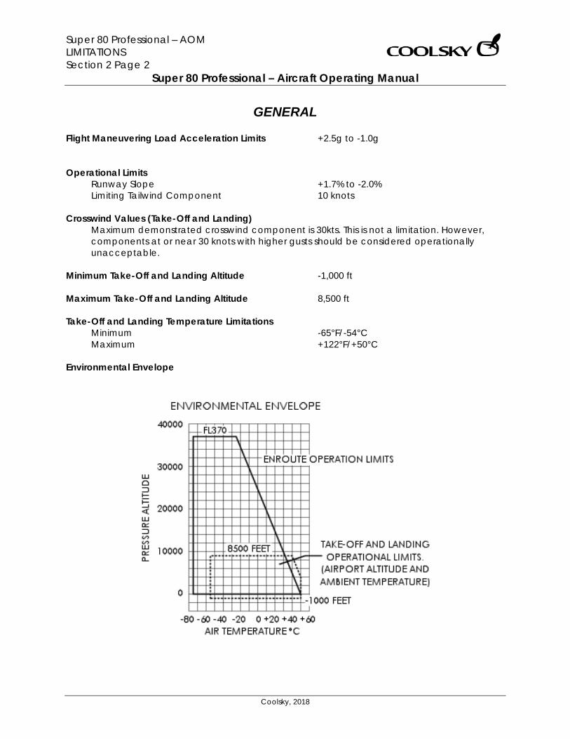
GENERAL Flight Maneuvering Load Acceleration Limits +2.5g to -1.0g Operational Limits
Runway Slope +1.7% to -2.0% Limiting Tailwind Component 10 knots
Crosswind Values (Take-Off and Landing)
Maximum demonstrated crosswind component is 30kts. This is not a limitation. However, components at or near 30 knots with higher gusts should be considered operationally unacceptable.
Minimum Take-Off and Landing Altitude -1,000 ft Maximum Take-Off and Landing Altitude 8,500 ft Take-Off and Landing Temperature Limitations
Minimum -65°F/-54°C Maximum +122°F/+50°C
Environmental Envelope
Super 80 Professional – AOM LIMITATIONS Section 2 Page 3
Super 80 Professional – Aircraft Operating Manual
Coolsky, 2018
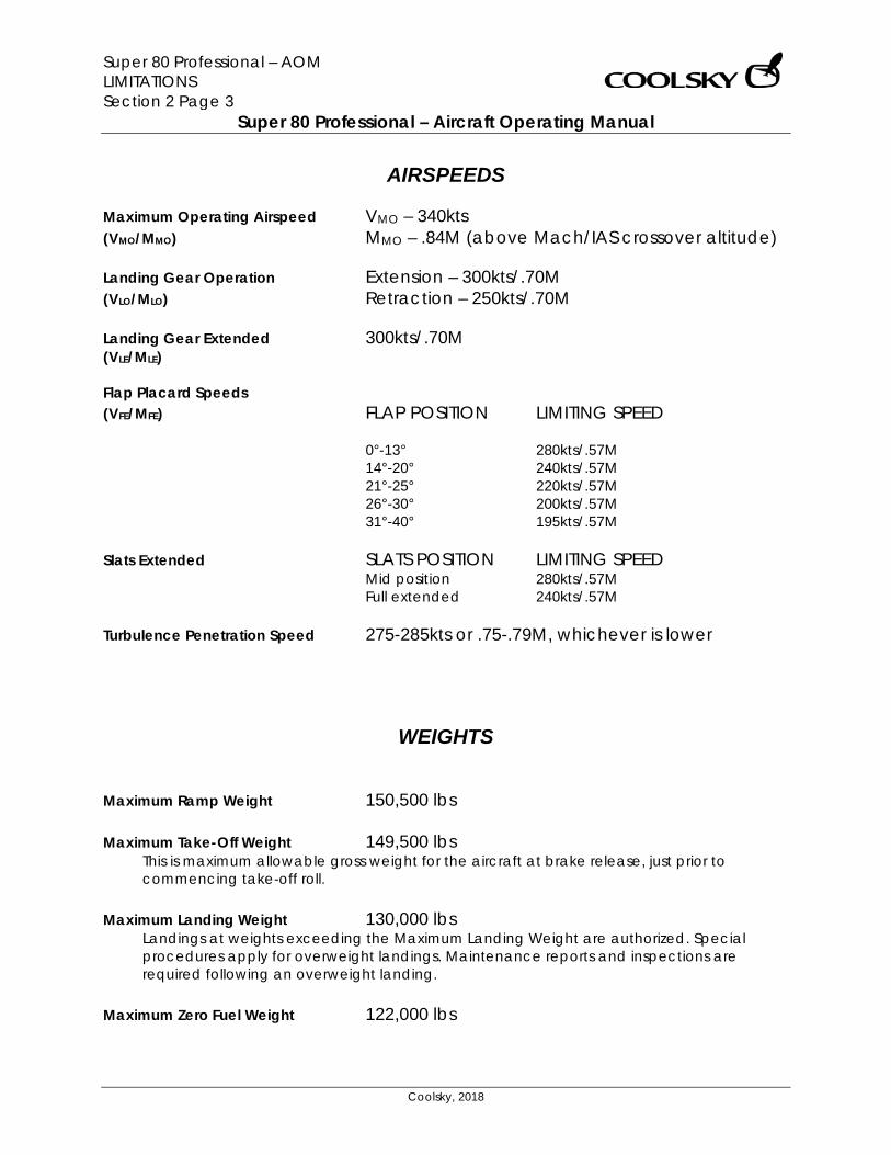
AIRSPEEDS Maximum Operating Airspeed VMO – 340kts (VMO/MMO) MMO – .84M (above Mach/IAS crossover altitude) Landing Gear Operation Extension – 300kts/.70M (VLO/MLO) Retraction – 250kts/.70M Landing Gear Extended 300kts/.70M (VLE/MLE) Flap Placard Speeds (VFE/MFE) FLAP POSITION LIMITING SPEED 0°-13° 280kts/.57M 14°-20° 240kts/.57M 21°-25° 220kts/.57M 26°-30° 200kts/.57M 31°-40° 195kts/.57M Slats Extended SLATS POSITION LIMITING SPEED Mid position 280kts/.57M Full extended 240kts/.57M Turbulence Penetration Speed 275-285kts or .75-.79M, whichever is lower
WEIGHTS Maximum Ramp Weight 150,500 lbs Maximum Take-Off Weight 149,500 lbs
This is maximum allowable gross weight for the aircraft at brake release, just prior to commencing take-off roll.
Maximum Landing Weight 130,000 lbs
Landings at weights exceeding the Maximum Landing Weight are authorized. Special procedures apply for overweight landings. Maintenance reports and inspections are required following an overweight landing.
Maximum Zero Fuel Weight 122,000 lbs
Super 80 Professional – AOM NORMAL PROCEDURES Section 3 Page 0
Super 80 Professional – Aircraft Operating Manual
Coolsky, 2018
SECTION 3
NORMAL PROCEDURES
Super 80 Professional – AOM NORMAL PROCEDURES Section 3 Page 1
Super 80 Professional – Aircraft Operating Manual
Coolsky, 2018
TABLE OF CONTENTS
SECTION 3: NORMAL PROCEDURES 0
TABLE OF CONTENTS ................................................................................................................. 1 GENERAL .................................................................................................................................... 2 NORMAL PROCEDURE CHECKLIST.......................................................................................... 3 ORIGINATION PRE-FLIGHT INSPECTION .................................................................................. 5 COCKPIT CLEAN-UP INSPECTION ......................................................................................... 13 BEFORE STARTING ENGINES ................................................................................................... 16 PRIOR TO ENGINE START OR PUSHOUT ................................................................................. 20 APU START ................................................................................................................................. 21 ENGINE START .......................................................................................................................... 23 POWER BACK FROM GATE .................................................................................................... 25 TAXI ............................................................................................................................................ 26 BEFORE TAKE-OFF .................................................................................................................... 28 TAKE-OFF .................................................................................................................................. 30 AFTER TAKE-OFF – CLIMB ........................................................................................................ 31 CRUISE ....................................................................................................................................... 33 DESCENT ................................................................................................................................... 34 BEFORE LANDING .................................................................................................................... 36 LANDING .................................................................................................................................. 37 AFTER LANDING ....................................................................................................................... 38 PARKING ................................................................................................................................... 40
Super 80 Professional – AOM NORMAL PROCEDURES Section 3 Page 2
Super 80 Professional – Aircraft Operating Manual
Coolsky, 2018
GENERAL Normal Procedures Checklist The Normal Procedure Checklists are used to insure that all important safety items have been accomplished. The items in the Checklist cannot be considered accomplished until all of the expanded procedures associated with that item have been accomplished. Crew Duties Normally crew duties are divided between the Captain and First Officer during ground operations and between pilot-flying and pilot-not-flying during flight. The Captain is responsible for ensuring that all normal procedure checklists are accomplished at the proper time. Normally the pilot-not-flying will accomplish the appropriate checklist and notify the pilot-flying when the checklist has been completed. Auto-Flight/Altitude Clearance Procedures Normally when the autopilot is engaged, the pilot-flying will control the Flight Guidance panel. When the autopilot is not engaged, the pilot-flying will normally call for changes to be made to the Flight Guidance panel by the pilot-not-flying. Both pilots should be aware of all communications traffic and clearances.
Traffic Watch Both crew members shall maintain traffic watch during all phases of flight. Cabin Door Operation The cabin door(s) shall be closed for departure and opened on arrival by the Gate Agent, using the cabin door exterior control. Except for emergencies, do not request the Flight Attendant to open or close the door(s). Call the Gate Agent. Note: It is perfectly normal to have a gap between the cabin door and aircraft when the door is closed and the aircraft is unpressurized. This allows for negative pressure relief. The doors will become flush with the airframe when the aircraft pressurizes during the take-off roll. To open and close the doors of this aircraft use the following keyboard key combinations:
• Main Exit: SHIFT-E, 1 • Forward air stairs: SHIFT-E, 2 • Ventral (aft) air stairs: SHIFT-E, 3
Press SHIFT and E together, then release them and quickly hit 1, 2 or 3. Anti-Collision Lights The Anti-Collision lights shall be ON when the engines are about to best started or are running, and anytime the airplane is in motion, taxi or tow.
Super 80 Professional – AOM NORMAL PROCEDURES Section 3 Page 3
Super 80 Professional – Aircraft Operating Manual
Coolsky, 2018
NORMAL PROCEDURE CHECKLIST
BEFORE STARTING ENGINES LOGBOOK ............................................................... CHECKED RUDDER PEDALS AND
SEATS ..................................... ADJUSTED AND LOCKED WINDOWS ......................................... CLOSED AND LOCKED O2 PANELS/INTERPHONE/
O2 PRESSURE .................................. SET AND CHECKED EMERGENCY LIGHTS .................................................. ARMED PROBE HEAT ........................................ CHECKED AND CAPT WINDSHIELD ANTI-ICE ....................................................... ON ANTI-SKID ........................................................................... OFF PRESSURIZATION .................................... AUTO (UP) AND SET AIR COND SHUTOFF ...................................................... AUTO FLIGHT GUIDANCE PANEL ..................... SET AND CHECKED FLT INSTR/SWITCHES/BUGS ........ SET AND CROSSCHECKED FUEL PANEL/QUANTITY AND
DISTRIBUTION ...................... SET AND CROSSCHECKED GEAR HANDLE AND LIGHTS ................. DOWN AND GREEN TRANSPONDER ................................................................... SET STABILIZER TRIM ................................................................... SET SPOILER LEVER ................................................................... RET THROTTLES .................................................................. CLOSED TAKE-OFF WARNING .............................................. CHECKED FUEL LEVERS ...................................................................... OFF FLAPS/SLATS ................................................... UP/RETRACTED AILERON/RUDDER TRIM ...................................... ZERO/ZERO PARKING BRAKE/PRESSURE .....................PARKED/NORMAL SHOULDER HARNESSES ..................................................... ON FLIGHT FORMS......................................................... CHECKED NO SMOKING SIGNS ......................................................... ON FIVE MINUTES PRIOR TO DEPARTURE SEAT BELT SIGNS ................................................................. ON
PRIOR TO ENGINE START OR PUSH OUT GALLEY POWER ................................................................ OFF ENGINE IGNITION ...................................................... CONTIN FUEL PUMPS ........................................................................ ON AUX HYDRAULIC PUMP ..................................................... ON ANTI-COLLITION/EXTERIOR LIGHTS ......... ON/AS REQUIRED DOOR ANNUNCIATOR .................................................... OUT AIR CONDITIONING SUPPLY SWITCHES ......................... OFF
TAXI BEFORE TAXI OR POWERBACK GALLEY POWER .................................................................. ON ENGINE ANTI-ICE .............................................. AS REQUIRED HYDRAULIC PUMPS ........................... CHECKED AND HI/ON TAXI APU .................................................................... AS REQUIRED PNEU X-FEED (One engine taxi) ............ L CLOSED/R OPEN ANTI-SKID (After leaving ramp area) ........................... ARM R ENG (One engine taxi) ................................... SHUTDOWN FLIGHT CONTROLS ................................................. CHECKED FGS .......................................................................... T/O MODE TRANSPONDER .................................................................... TA
BEFORE TAKE-OFF (Mechanical Checklist) FLT INST & BUGS ...................................... SET AND CHECKED ANTI-ICE ............................................................. AS REQUIRED FLAPS AND SLATS .................................................... TAKE-OFF STAB TRIM ............................................................................ SET APU/PNEU X-FD’S ............................. AS REQUIRED/CLOSED ANTI-SKID/ABS ................... ARMED/TAKE-OFF AND ARMED SPOILER LEVER ............................................................ ARMED TO PA/PACKS .............................. COMPLETE/AS REQUIRED ANNUNCIATOR LIGHTS .......................................... CHECKED NOSE LIGHTS ................................................................ BRIGHT
AFTER TAKE-OFF – CLIMB GEAR ....................................................... UP AND NO LIGHTS SPOILER LEVER ....................................................... DISARMED AUTO BRAKES ....................................... OFF AND DISARMED FLAPS AND SLATS ............................................ UP/NO LIGHTS PRESSURIZATION AND AIR COND ........................ CHECKED TRANSPONDER .............................................................. TA/RA 10,000FT MSL ENGINE IGNITION ............................................. AS REQUIRED FUEL SYSTEM ............................................................ CHECKED STERILE COCKPIT ............................................. CABIN CHIME ALTIMETERS .............................. RESET AND CROSSCHECKED HYDRAULIC PUMPS ................................................. LOW/OFF 18,000FT MSL EXTERIOR LIGHTS .............................................. AS REQUIRED ALTIMETERS .............................. RESET AND CROSSCHECKED
Super 80 Professional – AOM NORMAL PROCEDURES Section 3 Page 4
Super 80 Professional – Aircraft Operating Manual
Coolsky, 2018
CRUISE ENG SYNC .......................................................................... ON FIRST FLIGHT OF DAY ITEMS ................................... CHECKED DELAY CODES IN ACARS ................................ AS REQUIRED
DESCENT LANDING DATA ..................................................... PREPARED PRESSURIZATION ..................................... SET AND CHECKED ENG SYNC ......................................................................... OFF ENGINE IGNITION ...................................................... CONTIN ENGINE AND AIRFOIL ANTI-ICE ....................... AS REQUIRED WINDSHIELD ANTI-FOG .................................... AS REQUIRED SHOULDER HARNESSES ..................................................... ON DESCENDING THRU FL180 OR LEAVING CRUISE ALTITUDE, WHICHEVER IS LOWER EXTERIOR LIGHTS ............................................... AS REQUIRED ALTIMETERS .............................. RESET AND CROSSCHECKED HYDRAULIC PANEL .................................... HI/ON/CHECKED 10,000FT MSL STERILE COCKPIT ............................................. CABIN CHIME
BEFORE LANDING (Mechanical Checklist) ALTIMETERS .............................. RESET AND CROSSCHECKED FLT INST & BUGS .......................... SET AND CROSSCHECKED SEAT BELT/NO SMK ............................................................ ON GEAR................................................... DOWN, THREE GREEN SPOILER LEVER ............................................................ ARMED AUTO BRAKES .................................................... AS REQUIRED FLAPS & SLATS ................................................................ LAND ANNUNCIATOR LIGHTS .......................................... CHECKED
AFTER LANDING – TAXI AUTOPILOT AND AUTOTHROTTLE SWITCHES .................. OFF LANDING LIGHTS ............................................................... OFF SPOILER LEVER .................................................................... RET AUTO BRAKES .................................................... OFF/DISARM PNEU XFEED (One engine taxi) ............. R OPEN/L CLOSED FLAPS/SLATS ................................................... UP/RETRACTED RADAR ................................................................................ OFF TRANSPONDER ................................................................. STBY ANTI-SKID ............................................................................ OFF BRAKE PRESSURE .................................................... MONITOR APU .................................................................... AS REQUIRED R ENG (One engine taxi) ................................... SHUTDOWN
PARKING BRAKES ....................................................................... PARKED SEAT BELT SIGN .................................................................. OFF PNEU XFEED VALVES ..................................................... OPEN APU OR EXTERNAL POWER ............................... ESTABLISHED FUEL LEVERS ....................................................................... OFF ANTI-COLLISION/EXTERIOR LIGHTS......... OFF/AS REQUIRED ENGINE IGNITION .............................................................. OFF FUEL PUMPS........................................................................ OFF EMERGENCY LIGHTS ......................................................... OFF PROBE HEAT ....................................................................... OFF ANTI-ICE .............................................................................. OFF AIR CONDITIONING ......................................... AS REQUIRED OIL/HYD/O2 QUANTITIES ....................................... CHECKED ARRIVAL REPORT .............................................. AS REQUIRED LOGBOOK ........................................................... COMPLETED FD SWITCHES OFF .............................................................. OFF O2 PANEL SUPPLY LEVERS ................................................ OFF COCKPIT LIGHTS ............................................... AS REQUIRED ALL PASSENGERS HAVE DEPLANED GALLEY POWER ................................................................. OFF AIR CONDITIONING .......................................................... OFF APU .................................................................... AS REQUIRED BATTERY SWITCH ........................................................ ON/OFF POST FLIGHT INSPECTION ................................ AS REQUIRED
Super 80 Professional – AOM NORMAL PROCEDURES Section 3 Page 5
Super 80 Professional – Aircraft Operating Manual
Coolsky, 2018
ORIGINATION PRE-FLIGHT INSPECTION ORIGINATION PRE-FLIGHT INSPECTION (Procedure)
The Origination Pre-Flight Inspection is accomplished on the first origination flight of the day for the aircraft and anytime the condition of the aircraft is in doubt.
WALK-AROUND INSPECTION ...................................................................................... COMPLETE
1. Not simulated. COCKPIT SAFETY INSPECTION BATTERY SWITCH ....................................................................................................................... ON
2. Set the battery switch to the ON position. COCKPIT LIGHTS ...................................................................................................... AS REQUIRED
3. Set the Cockpit Flood light switch to OFF, or as required. 4. Turn on the Center Instrument & Pedestal Digital lights. 5. Turn on the Instrument Panel Digital lights. 6. Turn on the Flight Guidance Control Panel Digital lights.
HYDRAULIC PANEL ............................................................................................................ CHECK
7. Set the Transfer Pump switch to OFF. 8. Set both Engine Pump switches to HI. 9. Set the Auxiliary Pump switch to OFF.
GEAR HANDLE .................................................................................................................... DOWN
10. Confirm that the gear handle is down and that all the three green gear lights are on. CIRCUIT BREAKERS ............................................................................................................ CHECK
11. Not simulated. COCKPIT INITIAL PREPARATION APU PWR and EXT PWR ........................................................................................................... OFF
12. Set the APU PWR switch to OFF. 13. Set the EXT PWR switch to OFF. 14. Note: The APU PWR and EXT PWR switches on the Ground Service Elec Pwr Panel must be
OFF before connecting APU or External Power to main AC buses. APU (When required) .......................................................................................................... START
15. Please refer to STARTING APU Procedure guide on how to start the APU. EMERGENCY LIGHTS.............................................................................................................. ARM
16. Set the EMER LTS switch to ARM. GALLEY POWER ........................................................................................................................ ON
17. Set the Galley Power switch to ON.
Super 80 Professional – AOM NORMAL PROCEDURES Section 3 Page 6
Super 80 Professional – Aircraft Operating Manual
Coolsky, 2018
CABIN ALT CONTROL LEVER/POSITION INDICATOR .................................. AUTO/VALVE OPEN 18. Check that the CABIN ALT Control Lever is in the AUTO (up) position (Yellow handle, not
the wheel). 19. Check that the outflow valve indicator indicates VALVE OPEN. Full forward indicates
valve closed, full aft indicates valve fully open. Note: If the valve is only partially open, that is ok.
PNEUMATICS AND AIR CONDITIONING ................................................................. ESTABLISHED
20. Set both Pneumatic X-Feed handles to the OPEN (up) position. 21. Check that the APU AIR switch is set to ON or COLDER. 22. Set both Air Conditioning Supply switches to AUTO. 23. Set the Air Conditioning Recirculation Fan to AUTO. 24. Set the CKPT TEMP selector to AUTO. 25. Set the CABIN TEMP selector to AUTO. 26. Set the AIR COND SHUTOFF switch to AUTO. 27. Set the RAM AIR switch to OFF.
EXTERIOR LIGHTS ................................................................................................... CHECK LIGHTS
28. Check the exterior lights of the aircraft. (Not simulated in the panel) FLAP HANDLE/INDICATOR ................................................................................................. AGREE
29. Make sure the flaps/slats handle is in the UP/RET position. 30. Check that the flap/slat handle and indicator agree.
ANTI-SKID ................................................................................................................ TEST AND OFF
31. Set the ANTI-SKID switch to ARM. 32. Hold the ANTI-SKID TEST CHK switch to TEST. Check that all four anti-skid lights come on. 33. Set the ANTI-SKID switch back to OFF.
PARKING BRAKE ............................................................................................................... PARKED
34. The parking brake should be on. (Raised position) 35. Check that the Parking Brake light is on. 36. Check that the Brake Pressure gauge reads above the red band.
SHOULDER HARNESSES ...................................................................................................... CHECK
37. Check the condition of the shoulder harnesses. (Not simulated) LOGBOOK .......................................................................................................................... CHECK
38. Check the aircraft papers. (Not simulated) CHECKLISTS ........................................................................................................ CHECK ABOARD
39. Make sure you have all applicable checklists onboard with you. COCKPIT AREA INSPECTION CREW LIFE VESTS, O2 MASKS, SMOKE GOOGLES ........................................... CHECK ABOARD
40. Not simulated.
Super 80 Professional – AOM NORMAL PROCEDURES Section 3 Page 7
Super 80 Professional – Aircraft Operating Manual
Coolsky, 2018
FLIGHT CREW OXYGEN SUPPLY CYLINDER ...................................................................... CHECK 41. Not simulated.
PASS OXY MASK............................................................................................ NORM (GUARDED)
42. Not simulated. PROTECTIVE BREATING EQUIPMENT ................................................................................. CHECK
43. Not simulated. COCKPIT EMERGENCY EQUIPMENT ................................................................. CHECK ABOARD
44. Not simulated. SPARE BULB KIT .................................................................................................................. CHECK
45. Not simulated. FINAL COCKPIT PREPARATION MAINTENANCE INTERPHONE .................................................................................................. OFF
46. Set the Maintenance Interphone switch to OFF. FLIGHT RECORDER ...................................................................................................... TEST/NORM
47. Open the guard and set the Flight Recorder Test switch to TEST. 48. If the FLIGHT RECORDER OFF light stays off, the Flight Recorder operates properly. 49. Set the Flight Recorder Test switch back to NORM and put the guard back on.
FD CMD ........................................................................................................................... NORMAL
50. Set the FD CMD switch to NORM. CADC .............................................................................................................................. NORMAL
51. Set the CADC switch to NORM. VERT GYRO ..................................................................................................................... NORMAL
52. Set the VERT GYRO switch to NORM. IRS ............................................................................................................................................NAV
53. Set both IRS mode select switches to NAV. COCKPIT VOICE RECORDER............................................................................................. CHECK
54. Press the Cockpit Voice Recorder Test switch. 55. Observe the TEST MONITOR METER as a test signal is being sent to the Voice Recorder. No
reading on the meter indicates a failure. ELECTRICAL SYSTEM .......................................................................................................... CHECK
56. Check that both CSD switches are guarded. 57. Set the L GEN and R GEN switches to RESET and then back to ON. 58. Set the AC BUS X TIE switch to AUTO. 59. Set the DC BUS X TIE switch to OPEN.
Super 80 Professional – AOM NORMAL PROCEDURES Section 3 Page 8
Super 80 Professional – Aircraft Operating Manual
Coolsky, 2018
EMERGENCY POWER ......................................................................................... CHECK AND OFF 60. Set the Emergency Power switch to ON. 61. Check that EMER PWR IN USE light comes on. 62. Set the Emergency Power switch back to OFF.
WING TANK FUEL PUMPS ......................................................................................................... OFF
63. Turn off all, left and right, wing tank fuel pumps. If a pump is being used for APU operation, leave it on.
CENTER TANK FUEL PUMPS ................................................................................................ CHECK
64. Turn off fuel pump used for APU operation. 65. Check each of the center tank fuel pumps individually, checking that both the L and R
INLET FUEL PRESS LOW lights go out when each pump is turned on and comes back on when the pump is turned off. Note: The Start Pump should be off.
66. Turn back on fuel pump used for APU operation. IGNITION .................................................................................................................................. OFF
67. Set the Ignition switch to OFF. FUEL HEAT ................................................................................................................................. OFF
68. Set both FUEL HEAT switches to OFF. START SWITCHES (L & R) .......................................................................................................... OFF
69. Set both engine start switches to OFF. (Guarded position) NO SMOKING ........................................................................................................................... ON
70. Set the NO SMOK switch to ON. SEAT BELT .................................................................................................................................. OFF
71. Set the SEAT BELT switch to OFF. PROBE HEAT .................................................................................................... CHECK AND CAPT
72. Rotate the METER SEL & HEAT switch to all positions and check for a reading on the HEATER CUR gauge (except for RAT PROBE position) and that the PITOT/STALL HEATER OFF light remains out.
AIR FOIL ANTI-ICE.................................................................................................................... OFF
73. Set the Air Foil Anti-ice switch to OFF. WINDSHIELD ANTI-FOG ........................................................................................................... OFF
74. Set the Windshield Anti-Fog switch to OFF. WINDSHIELD ANTI-ICE .............................................................................................................. ON
75. Set the Windshield Anti-Ice switch to ON. Note: If the windshield have been cold soaked overnight, they may require up to 30 minutes to warm up thoroughly.
Super 80 Professional – AOM NORMAL PROCEDURES Section 3 Page 9
Super 80 Professional – Aircraft Operating Manual
Coolsky, 2018
ENGINE ANTI-ICE..................................................................................................................... OFF 76. Set both Engine Anti-Ice switches to OFF.
ENGINE SYNC .......................................................................................................................... OFF
77. Set the ENG SYNC switch to OFF. GROUND PROXIMITY WARNING SYSTEM ......................................................... TEST AND NORM
78. Set the GPWS switch to TEST (the switch is spring loaded back to NORM). 79. You should hear the aural alert “Whoop Whoop” followed by “Pull up” and “Glideslope”.
The GPWS FAIL light should also come on, together with… 80. …the GPWS and BELOW G/S lights during the test.
CIRCUIT BREAKER AND STANDBY COMPASS LIGHTS............................................ AS REQUIRED
81. Set the CKT BKR LT switch to OFF, or as required. 82. Set the STBY COMP LT switch to OFF, or as required.
THUNDERSTORM LIGHT ............................................................................................................ OFF
83. Set the THNDRSRM LT switch to OFF. COCKPIT FLOOD LIGHT ........................................................................................... AS REQUIRED
84. Set the CKPT FLOOD switch to OFF, or as required. OVERHEAD CONSOLE LIGHTS ................................................................................ AS REQUIRED
85. Set the OVHD CONSOLE LTS knobs to OFF, or as required. STALL WARNING ...................................................................................................................... TEST
86. Set the STALL TEST switch to SYS 1 (Momentary). This will test Stall Warning system 1. The stall warning horn should sound, followed by the vocal alert “Stall”.
87. The STALL warning light should come on (flashing), together with the PUSH TO INHIBIT light (steady).
88. Repeat test for system 2. MAX SPEED WARNING ............................................................................................................ TEST
89. Set the MAX SPD WARN TEST switch to SYS 1. Check that audio clacker sounds followed by the vocal warning “Overspeed” is heard.
90. Repeat test for system 2. YAW DAMPER ........................................................................................................................... ON
91. Set the YAW DAMP switch to ON. 92. Check that the YAW DAMP OFF light is out.
MACH TRIM COMPENSATION ........................................................................................... NORM
93. Set the MACH TRIM COMP switch to NORM. 94. Check that the MACH TRIM INOP light is out.
AIR CONDITIONING ...................................................................................................... CHECKED
95. Check cabin and cockpit temperature and adjust as necessary.
Super 80 Professional – AOM NORMAL PROCEDURES Section 3 Page 10
Super 80 Professional – Aircraft Operating Manual
Coolsky, 2018
RADIO RACK ........................................................................................................................... FAN 96. Set the RADIO RACK switch to FAN.
CABIN PRESSURIZATION ........................................................................................................... SET
97. Set the System Selector switch to PRIMARY. 98. Check that the STDBY ON and TRANSFER LOCKOUT lights are out. 99. Set the LDG ALT to Departure Field Elevation. 100. Set the LDG BARO to Current Altimeter Setting (press “B” on your keyboard). 101. Set the RATE LIMIT knob to the center index. 102. Push the FLOW light to test it.
RAIN REPELLENT ............................................................................................................ REPELLENT
103. Set the RAIN REPELLENT switch to REPELLENT. WINDSHIELD WIPER .................................................................................................................. OFF
104. Set the Windshield Wiper switch to PARK, to make sure the wiper is properly parked, and then back to OFF.
ANNUNCIATOR/DIGITAL LIGHTS ............................................................................................ TEST
105. Push the ANNUN/DIGITAL LTS TEST switch to test all Annunciator and digital lights in the cockpit. Carefully check all the lights on the overhead panel, main panel and pedestal for malfunction.
AUTOLAND PRE-FLIGHT TEST .................................................................................. ACCOMPLISH
106. Set both VHF radios to the same ILS frequency (any frequency will do, such as for example 110.90). (Click the lower left number to switch between the two VHF radios)
107. Set both course readouts to the same course (any course will do, for example 340). 108. Set the FD switch to FD. 109. Check that the NO AUTOLAND light on the FMA is out. 110. Press the AUTO LAND button. 111. Check that the NO AUTOLAND light flashes for a short while. If the light comes on
steady, the test has failed. If the light goes out, the test has completed successfully. STATIC AIR SELECTOR ......................................................................................................... NORM
112. Set the Static Air Selector switch to the NORM position. FLIGHT INSTRUMENTS ......................................................................................................... CHECK
113. Turn on the ND and adjust the brightness of the display using the knob on the EFIS Dimmer panel.
114. Turn on the PFD and adjust the brightness of the display using the knob on the EFIS Dimmer panel.
115. Turn on the TCAS display and adjust the brightness. 116. On the main instrument panel, check that all gyros are erect and no flags are visible on
any of the flight instruments. OIL QUANTITIES .................................................................................................................. CHECK
117. Check the quantity on the Engine Display Panel Oil Quantity readout.

Super 80 Professional – AOM NORMAL PROCEDURES Section 3 Page 11
Super 80 Professional – Aircraft Operating Manual
Coolsky, 2018
FIRE WARNINGS ....................................................................................................................... TEST 118. Press and hold the LOOPS TEST button to test the Engine Fire Warning system.
Check that the fire bell sounds, followed by vocal warning “Fire left engine” and “Fire right engine”.
119. Check that the red light in both ENG FIRE handles come on, both AGENT LOW lights come on, and both MASTER CAUTION and MASTER WARNING lights come on.
120. Also, check that all the FIRE DETECTOR LOOP lights on the ENGINE FIRE DETECT SYS panel come on during the test. (All switches should be in the BOTH position)
REVERSE THRUST AND UNLOCK LIGHTS .................................................................................. OUT
121. Check that Engine Reverse Thrust lights and Engine Reverse Unlock lights for both engines are out.
ENGINE INSTRUMENTS ....................................................................................................... CHECK
122. Check that all engine instruments read normal (zero). THRUST RATING SYSTEM .......................................................................................................... TEST
123. Push and hold the TEST button on the TRP. RAT should indicate +12°C. EPR LIM should indicate 2.04. Mode Selector lights and NO MODE light should be out.
124. Release the test button. RAT should indicate ambient temperature. EPR LIM should indicate 2.00 with failure flag in view. NO MODE light should come on. All Mode Selector lights should be out.
125. Press TO to turn the NO MODE light off. FUEL QUANTITY ........................................................................................................................ TEST
126. Push the Fuel Quantity Test button to test the Fuel Quantity Indication System. Each individual tank quantity indicator should indicate 3000 LBS. The total fuel quantity should read 9000 LBS, and Zero Fuel Weight should indicate current ZFW plus 9000 LBS.
FUEL PANEL, QUANTITY AND DISTRIBUTION ..................................................................... CHECK
127. Check that total fuel on board is sufficient for the planned flight. 128. Check the current fuel distribution against the Fuel Distribution Guide. (The Fuel
Distribution Guide can be found in the Aircraft Operating Manual, Section 15) FUEL USED RESET ................................................................................................................... RESET
129. Set the FUEL USED RESET switch to RESET (Momentary) to reset the fuel used counters.
HYDRAULIC SYSTEMS......................................................................................................... CHECK
130. Set the Aux Hydraulic Pump switch to OVRD and then to ON. 131. Check that the right hydraulics pressure gauge indicates within the top green
band for both positions with R HYD PRESS LOW light out. 132. Set the Transfer Pump switch to ON (Aux Hydraulic Pump still in OVRD or ON) 133. Check that the left hydraulics pressure gauge indicates within green band with
the L HYD PRESS LOW light out. 134. Check hydraulic quantities. Both readouts should read about 18 quarts. 135. Set the Transfer Pump switch back to OFF. 136. Set the Aux Hydraulic Pump switch back to OFF.
Super 80 Professional – AOM NORMAL PROCEDURES Section 3 Page 12
Super 80 Professional – Aircraft Operating Manual
Coolsky, 2018
BRAKE TEMPERATURE ............................................................................................................... TEST 137. Press and hold the Brake Temperature Test button. The Brake Temperature Gauge
should slowly rise to indicate about 450°C and the Overheat light should come on. RADAR ..................................................................................................................... TEST AND OFF
138. Set the Mode Selector switch to TEST. The radar screen should display a green, yellow and red test pattern. Set the Mode Selector switch back to OFF.
FMS/ACARS ..................................................................................... PREFLIGHT ACCOMPLISHED
139. Please refer to the FMS guide on how to pre-flight the FMS.
STABILIZER TRIM ................................................................................................................. CHECK 140. Move the LONG TRIM handle in both directions and check that the LONG TRIM
indicator moves in the appropriate direction.
SPOILER LEVER .......................................................................................................................... RET 141. The spoiler lever should be in the RET position (forward down position).
RUDDER HYDRAULIC CONTROL ............................................................................................. PWR
142. The RUD HYD CONT lever should be in the PWR position (forward). REVERSE LEVERS/THROTTLES............................................................................... DOWN/CLOSED
143. Advance both throttles, checking for freedom of movement. Check that the Take-off Configuration warning sounds are heard. Then close the throttles.
FUEL CROSSFEED VALVE ......................................................................................................... OFF
144. Set the FUEL X FEED lever to OFF (forward). FUEL LEVERS ............................................................................................................................. OFF
145. Both Fuel Levers should be in the down and OFF position. (Under the throttles handles)
AILERON AND RUDDER TRIM .............................................................................. CHECK AND SET
146. Check travel or both aileron and rudder trim in all directions. Then set both to zero. AUTO BRAKE .....................................................................................................OFF AND DISARM
147. Set the AUTO BRAKE Selector to OFF. 148. Set the AUTO BRAKE ARM/DISARM switch to DISARM.
Super 80 Professional – AOM NORMAL PROCEDURES Section 3 Page 13
Super 80 Professional – Aircraft Operating Manual
Coolsky, 2018
COCKPIT CLEAN-UP INSPECTION COCKPIT CLEAN-UP INSPECTION
For flights other than the first origination flight of the day for the aircraft, only the Cockpit Clean-Up Inspection needs to be accomplished.
WALK-AROUND INSPECTION .................................................................................... COMPLETED
1. Not simulated. PROTECTIVE BREATING EQUIPMENT ................................................................................. CHECK
2. Not simulated. SHOULDER HARNESSES ...................................................................................................... CHECK
3. Check the condition of the shoulder harnesses. (Not simulated) FLIGHT CREW OXYGEN SUPPLY CYLINDER ...................................................................... CHECK
4. Not simulated LOGBOOK .......................................................................................................................... CHECK
5. Check the aircraft papers. (Not simulated) CIRCUIT BREAKERS ............................................................................................................ CHECK
6. Not simulated. BATTERY SWITCH ....................................................................................................................... ON
7. Set the battery switch to the ON position.
EMERGENCY POWER ............................................................................................................... OFF 8. Set the Emergency Power switch to OFF.
APU PWR and EXT PWR Switches ........................................................................................... OFF
9. Set the APU PWR switch to OFF. 10. Set the EXT PWR switch to OFF.
APU (When required) .......................................................................................................... START
11. Please refer to STARTING APU Procedure guide on how to start the APU. EMERGENCY LIGHTS.............................................................................................................. ARM
12. Set the EMER LTS switch to ARM. FLIGHT RECORDER ...................................................................................................... TEST/NORM
13. Open the guard and set the Flight Recorder Test switch to TEST. 14. If the FLIGHT RECORDER OFF light stays off, the Flight Recorder operates properly. 15. Set the Flight Recorder Test switch back to NORM and the guard back on.
GALLEY POWER ........................................................................................................................ ON
16. Set the Galley Power switch to ON.
Super 80 Professional – AOM NORMAL PROCEDURES Section 3 Page 14
Super 80 Professional – Aircraft Operating Manual
Coolsky, 2018
CENTER TANK FUEL PUMPS ................................................................................................ CHECK 17. Turn off all fuel pumps. 18. Check each of the center tank fuel pumps individually, checking that both the L and R
INLET FUEL PRESS LOW lights go out when each pump is turned on and comes back on when the pump is turned off.
19. Turn back on fuel pump used for APU operation. PROBE HEAT .................................................................................................... CHECK AND CAPT
20. Rotate the METER SEL & HEAT switch to all positions and check for a reading on the HEATER CUR gauge (except for RAT PROBE position) and that the PITOT/STALL HEATER OFF light remains out.
WINDSHIELD ANTI-ICE .............................................................................................................. ON
21. Set the Windshield Anti-Ice switch to ON. Note: If the windshield have been cold soaked overnight, they may require up to 30 minutes to warm up thoroughly.
CABIN ALT CONTROL LEVER/POSITION INDICATOR .................................. AUTO/VALVE OPEN
22. Check that the CABIN ALT Control Lever is in the AUTO (up) position (Yellow handle, not the wheel).
23. Check that the outflow valve indicator indicates VALVE OPEN. PNEUMATICS AND AIR CONDITIONING ................................................................. ESTABLISHED
24. Set Pneumatic X-Feed handles to the OPEN (up) position. 25. Check that the APU AIR switch is set to ON or COLDER. 26. Set both Air Conditioning Supply switches to AUTO. 27. Set the Air Conditioning Recirculation Fan to AUTO. 28. Set CKPT TEMP selector to AUTO. 29. Set CABIN TEMP selector to AUTO. 30. Set AIR COND SHUTOFF switch to AUTO. 31. Set RAM AIR switch to OFF.
CABIN PRESSURIZATION ........................................................................................................... SET
32. Set the System Selector switch to PRIMARY. 33. Check that the STDBY ON and TRANSFER LOCKOUT lights are out. 34. Set the LDG ALT to Departure Field Elevation. 35. Set the LDG BARO to Current Altimeter Setting (press “B” on your keyboard). 36. Set the RATE LIMIT knob to the center index.
AUTOLAND PRE-FLIGHT TEST .................................................................................. ACCOMPLISH
37. Set both VHF radio to the same ILS frequency (any ILS frequency will do). (Click the lower left number to switch between the two VHF radios)
38. Set both course readouts to the same course (any course will do). 39. Set the FD switch to FD. 40. Check that the NO AUTOLAND light on the FMA is out. 41. Press the AUTO LAND button. 42. Check that the NO AUTOLAND light flashes for a short while. If the light comes on steady,
the test has failed. If the light goes out, the test has completed successfully.
Super 80 Professional – AOM NORMAL PROCEDURES Section 3 Page 15
Super 80 Professional – Aircraft Operating Manual
Coolsky, 2018
FUEL PANEL, QUANTITY AND DISTRIBUTION ..................................................................... CHECK 43. Check that total fuel on board is sufficient for the planned flight. 44. Check the current fuel distribution against the Fuel Distribution Guide. (The Fuel
Distribution Guide can be found in the Aircraft Operating Manual, Section 15) FUEL USED RESET ................................................................................................................... RESET
45. Set the FUEL USED RESET switch to RESET (Momentary) to reset the fuel used counters. GEAR HANDLE .................................................................................................................... DOWN
46. Confirm that the gear handle is down and that all the three green gear lights are on. FLAP HANDLE/INDICATOR ................................................................................................. AGREE
47. Make sure the flaps/slats handle is in the UP/RET position. 48. Check that the flap/slat handle and indicator agree.
HYDRAULIC QUANTITIES.................................................................................................... CHECK
49. Check hydraulic quantities. Both gauges should read well above the red band. TAKE-OFF WARNING SYSTEM ........................................................................................... CHECK
50. Advance both throttles, and check that the Take-off Configuration warning sounds are heard. Then close the throttles.
FMS/ACARS ..................................................................................... PREFLIGHT ACCOMPLISHED
51. Please refer to the FMS guide on how to preflight the FMS.
Super 80 Professional – AOM NORMAL PROCEDURES Section 3 Page 16
Super 80 Professional – Aircraft Operating Manual
Coolsky, 2018
BEFORE STARTING ENGINES BEFORE STARTING ENGINES (Checklist)
Please note that if you start with a cold aircraft (all systems off), you should go through the Cockpit Clean-up Procedure first in order to setup the aircraft before flight.
LOGBOOK ...................................................................................................................... CHECKED
1. Check aircraft and pilot logbooks. RUDDER PEDALS AND SEATS ................................................................ ADJUSTED AND LOCKED
2. Make sure the seats are properly adjusted and locked in the tracks. Use the Pilot Eye Locator to adjust your position. (Not simulated)
WINDOWS ................................................................................................. CLOSED AND LOCKED
3. All windows in the cockpit should be closed and locked. O2 PANELS/INTERPHONE/O2 PRESSURE ....................................................... SET AND CHECKED
4. Set the oxygen SUPPLY lever to ON. 5. Set the DILUTER DEMAND CONTROL lever to NORMAL OXYGEN. 6. Check the pressure on the oxygen pressure gauge. 7. Check and set the levers on the Audio Panel. For normal operation set VHF 1 and 2, and
the MKR lever to ON (up). Leave the rest in the OFF (off) position. EMERGENCY LIGHTS.......................................................................................................... ARMED
8. Set the emergency lights switch to ARM. PROBE HEAT ................................................................................................ CHECKED AND CAPT
9. Rotate the METER SELECTOR AND HEAT switch to the captain’s pitot tube (CAPT). This will turn on heating on all pitot tubes.
10. Check for a reading of the current flow to the captain’s pitot tube on the HEATER CURRENT gauge.
11. Also, check that the PITOT/STALL HEATER OFF light is out. WINDSHIELD ANTI-ICE .............................................................................................................. ON
12. Turn on windshield anti-ice. A ”hand-feel” test is required to verify the operation of the windshield anti-icing system.
ANTI-SKID ................................................................................................................................. OFF
13. Set the AUTO BRAKE Selector to OFF 14. Set the AUTO BRAKE ARM/DISARM switch to DISARM.
PRESSURIZATION ............................................................................................AUTO (UP) AND SET
15. Make sure the CABIN ALTITUDE CONTROL LEVER is in the up and auto position (Yellow handle, not the wheel).
16. Set the RATE LIMIT CONTROL KNOB to the center position, or as required. 17. Also, set the departure barometric pressure by pressing the ”B” key on your keyboard.

Super 80 Professional – AOM NORMAL PROCEDURES Section 3 Page 17
Super 80 Professional – Aircraft Operating Manual
Coolsky, 2018
AIR COND SHUTOFF ............................................................................................................. AUTO 18. Set the AIR CONDITION SHUTOFF switch to auto. This makes sure the air conditioning packs
are automatically shut-off in the event of an engine failure. FLIGHT GUIDANCE PANEL .............................................................................. SET AND CHECKED
19. The Flight Guidance Panel is located on the glareshield. 20. Set the navigation radios as desired for the flight. 21. Set the course as desired for the flight. 22. Set the Flight Director switches to FD. 23. Set Auto-throttle switch to OFF, and speed readout to 250 knots. 24. Set the heading to runway heading. 25. Set the Autopilot master switch to OFF. 26. Set the Digital Flight Guidance Computer 1-2 switch as desired. 27. Use the Altitude Selector to set the first level off altitude in the Altitude Preselect Readout.
FLT INSTR/SWITCHES/BUGS ................................................................ SET AND CROSSCHECKED
28. First, set the clock to correct Zulu time. (Use the P3D menu to set time) 29. Check the Mach/Airspeed indicator. The needle should read 0 knots. The Mach readout
should read .150 Mach. The bugs should be set to V1, V2, flap and slat retract, and clean minimum maneuvering speed. All these speeds can be found in the speed booklet.
30. Check and set the altimeter using the BARO knob. You can also reset the barometric pressure setting by pressing the ”B” key on your keyboard.
31. Also set and check the Standby Altimeter. 32. Check the Radio Distance Magnetic Indicator. No flags should be visible. Set the
VOR/ADF Selectors as desired. Compare the heading to the heading on the ND. 33. The ND should have no flags visible. 34. The Vertical Speed Indicator should read zero. 35. The Standby Airspeed Indicator should read zero. 36. The Standby Attitude Indicator should have no flags visible, the gyro should be erect –
level horizon, and the airplane symbol should be properly positioned. 37. On the Thrust Rating Indicator, select TO Mode for a standard thrust take-off. 38. On the Engine Pressure Ratio gages, check that the bugs are set according to the EPR
LIM Readout on the TRP. (You may need to push in the EPR knob) FUEL PANEL/QUANTITY AND DISTRIBUTION ...................................... SET AND CROSSCHECKED
39. All Tank Pump switches should be in the OFF position. However, a pump being used for APU operation should be left on.
40. Set the Zero Fuel Weight according to the Weight & Balance sheet. You will find Weight & Balance data in the Super 80 Dispatch Center.
41. The Fuel Crossfeed Valve should be closed (forward down position). 42. Now, check the fuel quantity and distribution. Confirm that the total fuel onboard is
sufficient for the planned flight. 43. Also, check the fuel distribution according to the Fuel Distribution Guide. (The Fuel
Distribution Guide can be found in the manual)
Super 80 Professional – AOM NORMAL PROCEDURES Section 3 Page 18
Super 80 Professional – Aircraft Operating Manual
Coolsky, 2018
GEAR HANDLE AND LIGHTS ......................................................................... DOWN AND GREEN 44. Confirm that the gear handle is down and that all the three green gear lights are on.
TRANSPONDER .......................................................................................................................... SET
45. Set the Function Selector to STBY. 46. Set the TCAS Range switch to 10, or as required. 47. Set the ABOVE/BELOW switch to ABOVE. 48. Set the Transfer switch to 1. 49. And finally, set the transponder code in the Code Readout as instructed by ATC.
STABILIZER TRIM ........................................................................................................................ SET
50. To set the stabilizer trim we need to input CG and FLAP setting to the Take-off Condition Computer. First, set the CG according to the Weight & Balance sheet. (See Super 80 Dispatch Center)
51. Second, set the FLAP setting according to the Weight & Balance sheet, or as desired. 52. And finally, align the LONG TRIM indicator (white) with the LONG TRIM TAKE-OFF Position
Indicator (green) using the LONG TRIM handle. SPOILER LEVER .......................................................................................................................... RET
53. The spoiler lever should be in the RET position (forward position). THROTTLES ......................................................................................................................... CLOSED
54. Both throttles should be closed and the reverse levers down. TAKE-OFF WARNING ..................................................................................................... CHECKED
55. Verify that the Take-off Warning system is operating properly. With the flaps and slats up and retracted, advance the throttles. The take-off warning horn sounds and the vocal annunciations of ”Fulaps” and ”Slat” are heard. The “u” in “Fulaps” is there on purpose to better distinguish it from “slats” in a noisy cockpit.
FUEL LEVERS ............................................................................................................................. OFF
56. Both Fuel Levers should be in the down and OFF position. (Under the throttles handles) FLAPS/SLATS .......................................................................................................... UP/RETRACTED
57. Make sure the flaps/slats are up and retracted. 58. Check that the flap/slat handle and indicator agree. 59. Check that the Slat lights are off.
AILERON/RUDDER TRIM .............................................................................................. ZERO/ZERO
60. Set both aileron trim and rudder trim to the centered position. PARKING BRAKE/PRESSURE ............................................................................ PARKED/NORMAL
61. The parking brake should be on. (Raised position) 62. Check that the Brake Pressure gauge reads above the red band.
SHOULDER HARNESSES ............................................................................................................. ON
63. Make sure you are securely strapped in.
Super 80 Professional – AOM NORMAL PROCEDURES Section 3 Page 19
Super 80 Professional – Aircraft Operating Manual
Coolsky, 2018
FLIGHT FORMS ............................................................................................................... CHECKED 64. Have you done your paperwork?
NO SMOKING SIGNS ............................................................................................................... ON
65. Set the No Smoking switch to ON. FIVE MINUTES PRIOR TO DEPARTURE SEAT BELT SIGNS ....................................................................................................................... ON
66. Set the Seat Belt switch to ON about 5 minutes before departure.
Super 80 Professional – AOM NORMAL PROCEDURES Section 3 Page 20
Super 80 Professional – Aircraft Operating Manual
Coolsky, 2018
PRIOR TO ENGINE START OR PUSHOUT PRIOR TO ENGINE START OR PUSH OUT (Checklist) GALLEY POWER ....................................................................................................................... OFF
1. Set the Galley Power switch to OFF. ENGINE IGNITION ............................................................................................................. CONTIN
2. Set the Engine Ignition switch to GND START & CONTIN.
FUEL PUMPS ............................................................................................................................... ON 3. Normally you would turn on all the fuel pumps. However, if the center tanks do not have
any usable fuel, leave them OFF. AUX HYDRAULIC PUMP ............................................................................................................ ON
4. Set the Auxiliary Hydraulic Pump switch to ON. Also check that both engine hydraulic pumps are in the LOW position.
ANTI-COLLITION/EXTERIOR LIGHTS ................................................................. ON/AS REQUIRED
5. Turn on the anti-collision light to alert ground personnel that the engines are about to be started.
6. Set the POS/STROBE light switch to BOTH. DOOR ANNUNCIATOR ............................................................................................................ OUT
7. Verify that all door annunciator lights are out. AIR CONDITIONING SUPPLY SWITCHES ................................................................................. OFF
8. Set the Air Conditioning switches to OFF. These switches may, at the Captain’s discretion be left in the AUTO position until just prior to positioning the first engine start switch to GND.
Super 80 Professional – AOM NORMAL PROCEDURES Section 3 Page 21
Super 80 Professional – Aircraft Operating Manual
Coolsky, 2018
APU START APU START (Procedure)
Use this procedure to start the APU both on the ground and in-flight. BATTERY SWITCH ....................................................................................................................... ON
1. Set the battery switch to the ON position. APU DOORS .......................................................................................................................... AUTO
2. Make sure the guarded switch is set to AUTO. Note that when the guard is on, the switch is in the AUTO position.
APU AIR .................................................................................................................................... OFF
3. Set the APU Air switch to OFF. APU FIRE CONT ................................................................................................................... NORM
4. Set the APU FIRE CONT switch to the NORM position. START PUMP.............................................................................................................. AS REQUIRED
5. If AC electric power is not available (no ground power connected and no engine running), set the START PUMP switch to ON. Otherwise, leave the switch in the OFF position.
FUEL BOOST PUMPS ................................................................................................. AS REQUIRED
6. If AC electric power is available (ground power connected and/or engine(s) running), set the RH Aft Fuel Boost Pump switch to ON. Note that you do not need to have both the Start Pump and a Fuel Boost Pump running simultaneously, only one of them is required.
APU MASTER ......................................................................................................... START/RELEASE
7. Momentarily move the APU MASTER switch to START (spring loaded back to RUN). 8. Check that the APU RPM and APU EGT start rising. 9. Check that the APU OIL PRESS LOW light goes out at or prior to 95% RPM.
APU RUNNING AND ELECTRICAL POWER ESTABLISHED
10. When APU RPM and APU EGT has stabilized… 11. …and APU power has been connected to the AC buses, continue the APU Start
procedure. (Both switches on and both lights on) FUEL BOOST PUMPS ................................................................................................. AS REQUIRED
12. Normally, the RH Aft Fuel Boost Pump is used for APU operation. However, the center tanks may also be used for APU operation at the Captain’s discretion. Set the RH Aft Fuel Boost Pump switch to ON.
START PUMP.............................................................................................................. AS REQUIRED
13. If the Start Pump was used to start the APU, set the Start Pump switch to OFF. APU AIR .................................................................................................................... AS REQUIRED
14. Set the APU Air switch to ON.

Super 80 Professional – AOM NORMAL PROCEDURES Section 3 Page 22
Super 80 Professional – Aircraft Operating Manual
Coolsky, 2018
PNEUMATIC PRESSURE .................................................................................................... NORMAL 15. The Pneumatic Pressure Gauge should indicate about 35 PSI.
PNEUMATIC X-FEED VALVES ............................................................................................... OPEN
16. Open both Pneumatic X-Feed handles (up position).
Super 80 Professional – AOM NORMAL PROCEDURES Section 3 Page 23
Super 80 Professional – Aircraft Operating Manual
Coolsky, 2018
ENGINE START ENGINE START (Procedure)
1. Before starting an engine you need a pneumatic pressure source. This can be bleed air from either the APU or bleed air from the other engine if that has already been started.
2. For a Crossbleed Start (bleed air from running engine) make sure both Pneumatic X-Feed
handles are open (up position). 3. For APU bleed air start, the APU must be running and… (Please refer to the APU START
procedure guide on how to start the APU) 4. …the APU Air switch must be set to ON… 5. …and the Pneumatic X-Feed handle for the engine you are about to start must be set to
OPEN. Set the left Pneumatic X-Feed handle to OPEN (up). 6. Check the Pneumatic Pressure Gauge. Optimum starting pressure is about 30-38 PSI. 7. Open the guard to the Left Engine Starter switch and set the switch to GND. 8. Check that the L START VALVE OPEN light comes on. 9. Check that the pneumatic pressure remains above 25 PSI. If the pneumatic pressure
drops below 25 PSI, be alert for a hung or hot start. 10. Check for increasing oil pressure. 11. Check for increasing N2. 12. Check for increasing N1. 13. Check for increasing hydraulic pressure. 14. At maximum motoring (minimum 20% N2)… 15. …set the left Fuel Lever to ON. (Under the throttle handle) 16. Monitor N1, EGT, N2 and Fuel Flow. 17. At 40% N2… 18. …set the Left Engine Starter switch back to OFF and put the guard back on. 19. Check that N2 stabilizes at about 50-60%.
Super 80 Professional – AOM NORMAL PROCEDURES Section 3 Page 24
Super 80 Professional – Aircraft Operating Manual
Coolsky, 2018
20. When the engine has stabilized at idle RPM, check the following: APU PWR (L) Power In Use Light should be out.
21. EXT PWR (L) Power In Use Light should be out. 22. L CSD OIL PRESS LOW light should be out. 23. L OIL PRESS LOW light should be out. 24. L HYD PRESS LOW light should be out. 25. EGT should indicate 300-480°C. 26. Fuel Flow should indicate 800-1100 LBS/hour. 27. If outside temperatures are below freezing, turn on left Engine Anti-Ice. 28. To start right engine, repeat the engine start procedure for the right engine.

Super 80 Professional – AOM NORMAL PROCEDURES Section 3 Page 25
Super 80 Professional – Aircraft Operating Manual
Coolsky, 2018
POWER BACK FROM GATE POWER BACK FROM GATE (Procedure)
1. Power back gate departure is only authorized when both crew members have received proper training. A minimum of two ground crew is required, one Guideman and one Wingwalker. The Guideman should be position in front of the aircraft, in clear view of both pilots. The Wingwalker should be positioned aft of the right wing. Depending on the situation and gate location, a second Wingwalker for the left wing might be required.
2. Both engines should be running before commencing with the procedure. See the Engine
Start procedure on how to start the engines. 3. Complete the BEFORE TAXI items on the Taxi checklist. 4. Flash nose wheel landing and taxi light once, to indicate to the Guideman that you are
ready to begin power back. To re-establish cockpit to ground communication, flash the nose light three times (not simulated).
5. At the direction of the Guideman (come forward signal), taxi the aircraft two or three feet forward, before going into reverse thrust. This is done as a safety precaution against blocked wheels.
6. Once the Guideman sees the aircraft moving forward, he will give the power back signal by rotating the wands horizontally in a circular motion.
7. Apply and hold the brakes to stop the forward motion and simultaneously set both engines to reverse idle thrust.
8. When both blue ENG REVERSE THRUST lights come on, release the brakes and drop both feet to the floor.
9. Monitor Guideman and establish reverse thrust for rearward movement. Do not exceed 1.3 EPR. Rearward speed should not exceed that of a normal walk.
10. If rearward speed is excessive, place one engine in forward thrust. 11. Turns during power back must be commanded by the Guideman. Upon the Guideman’s
signal, turn the steering wheel tiller in the direction of the Guideman’s lowered wand. Turns are made with reference to the Guideman’s left or right.
12. When the aircraft has reached the desired position, the Guideman will give the come forward signal.
13. Sharply come out of reverse, and apply forward thrust. 14. CAUTION: DO NOT USE BRAKES TO STOP REARWARD MOVEMENT. 15. Check that all reverse lights are out. 16. On the Guideman’s signal, establish forward movement or come to a full stop. 17. Flash nose wheel landing and taxi light once, to signal to the Guideman that you are
ready to taxi. 18. When the area is clear, the Guideman will give the standard departure salute.
SPECIAL CAUTIONS:
• The Guideman should never give the stop signal when the aircraft is in rearward movement. The come forward signal should be used to stop the aircraft.
• Do not use the brakes when the airplane is in rearward movement. • If the brakes are inadvertently applied during rearward movement and the aircraft starts
to tail tip, immediately move both throttles into forward thrust.
Super 80 Professional – AOM NORMAL PROCEDURES Section 3 Page 26
Super 80 Professional – Aircraft Operating Manual
Coolsky, 2018
TAXI TAXI (Checklist) BEFORE TAXI OR POWERBACK
The first part of the TAXI checklist is normally performed before the aircraft starts moving. GALLEY POWER ........................................................................................................................ ON
1. Set the Galley Power switch to ON. (…keeps the coffee warm…) ENGINE ANTI-ICE..................................................................................................... AS REQUIRED
2. In snowy or cold weather you should turn on the Engine Anti-Ice switches. Otherwise you may leave them in the OFF position.
HYDRAULIC PUMPS ................................................................................... CHECKED AND HI/ON
3. Set the Aux Pump switch to OFF. Set both engine hydraulic pump switches to LOW. 4. Then check that the L and R HYD PRESS LOW lights remain off with both engine hydraulic
pump switches in the LOW position. 5. Set both Engine Pump switches to HI (up). 6. Set the Auxiliary Pump switch back to ON (up). 7. Set the Transfer Pump switch to ON (up) in order to power both hydraulic systems in the
event of an engine or pump failure. TAXI
The second part of the TAXI checklist is normally performed while the aircraft is taxiing. Note that one engine taxi is only necessary when extended taxi is expected. Otherwise, taxi with both engines running and skip the one engine taxi items.
APU ........................................................................................................................... AS REQUIRED 1. Set the APU AIR switch to OFF. 2. Shut down the APU, by moving the APU MASTER switch to OFF. Leave the APU on if one
engine taxi is planned or supplemental bleed air for cabin cooling is required. 3. Set the APU DOORS switch to AUTO and put the guard back on. Note: When the guard is
on, the switch is automatically in the AUTO position. PNEU X-FEED (One engine taxi) .................................................................... L CLOSED/R OPEN
4. Prior to shutting down the right engine for one engine taxi, close the left Pneumatic X-feed Valve handle. Leave the Pneumatic X-feed Valve handles in the OPEN (up) position if both engines are to be used for taxi.
ANTI-SKID (After leaving ramp area) ................................................................................. ARM
5. Turn on the anti-skid system after leaving the ramp area. Set the ANTI-SKID switch to ARM. R ENG (One engine taxi) .......................................................................................... SHUTDOWN
6. Move the right Fuel Lever to the OFF position to shut down the right engine for one engine taxi.
Super 80 Professional – AOM NORMAL PROCEDURES Section 3 Page 27
Super 80 Professional – Aircraft Operating Manual
Coolsky, 2018
FLIGHT CONTROLS ......................................................................................................... CHECKED 7. Slowly move the rudder pedals, control wheel and control column to their extreme
positions checking for freedom of movement and normal control forces. 8. Check that the SPOILER DEPLOYED light comes on during aileron check. 9. Check that the ELEVATOR POWER ON light comes on when the control column is moved
full forward. FGS ............................................................................................................................... T/O MODE
10. Press the TO/GA button. 11. The pitch and roll FMA windows should annunciate TAK OFF. 12. The FD command bars should be wings level at or near the horizon line.
TRANSPONDER ........................................................................................................................... TA
1. Set the Function Selector to TA.
Super 80 Professional – AOM NORMAL PROCEDURES Section 3 Page 28
Super 80 Professional – Aircraft Operating Manual
Coolsky, 2018
BEFORE TAKE-OFF BEFORE TAKE-OFF (Mechanical Checklist)(Checklist)
Use the mechanical checklist on the pedestal to accomplish the items in the Before Takeoff checklist.
FLT INST & BUGS .............................................................................................. SET AND CHECKED
1. Make sure the bugs are set correctly on the Mach/Airspeed indicator. Use the Speed Cards to set the bugs for take-off.
2. The PFD should have no flags visible. 3. The Radio Altimeter should read zero. 4. The altimeters should read field altitude. 5. The Altimeter Reference Index should be set to Obstacle Clearance Altitude. (You will
need a map for the airfield you are departing from for this. Set zero if you don’t know OCA).
6. The RDMI should have no visible flags. 7. The ND should have no visible flags. 8. Cross check the Standby Altimeter with the Captain’s Altimeter. 9. The Standby Attitude Indicator should be erect and have no flags visible. 10. Make sure the ART switch is in the AUTO position (guarded position).
ANTI-ICE ................................................................................................................... AS REQUIRED
11. Set the Air Foil Anti-Ice switch to OFF. Turn the Air Foil Anti-ice switch back to ON after reaching 1000 feet if icing conditions exist or are anticipated.
FLAPS AND SLATS .......................................................................................................... TAKE-OFF
12. Set flaps for takeoff according to the Weight & Balance sheet, or as desired. 13. Verify slats are in the take-off position by observing the TAKEOFF light.
STAB TRIM .................................................................................................................................. SET
14. Check position of LONG TRIM Indicator (white) against LONG TRIM TAKEOFF Position Indicator (green). These should be aligned.
APU/PNEU X-FD’S .....................................................................................AS REQUIRED/CLOSED
15. If the APU is still running (after one engine taxi), shut down the APU by moving the APU Master switch to OFF.
16. Set the APU AIR switch to OFF. 17. Set the APU DOORS switch to OFF and put the guard back on. 18. Close both Pneumatic X-Feed handles (down position).
ANTI-SKID/ABS ..........................................................................ARMED/TAKE-OFF AND ARMED
19. Set the Anti-Skid switch to ARM. 20. Set the AUTO BRAKE Selector to TO. 21. Set the AUTO BRAKE ARM/DISARM switch to ARM.
SPOILER LEVER ................................................................................................................... ARMED
22. Arm the Spoiler lever (forward raised position).
Super 80 Professional – AOM NORMAL PROCEDURES Section 3 Page 29
Super 80 Professional – Aircraft Operating Manual
Coolsky, 2018
TO PA/PACKS ...................................................................................... COMPLETE/AS REQUIRED 23. The Captain should give the Take-off PA no less than 1 minute prior to departure. 24. When take-off is imminent, chime the cabin by pressing the ATTENDANT CALL button
once. Press the Attendant Call Reset light below to extinguish the light. 25. Set the Air Conditioning Supply switches to AUTO.
ANNUNCIATOR LIGHTS ................................................................................................. CHECKED
26. Check that the RUDDER TRAVEL UNRESTRICTED light is on. 27. Check that no other amber warning lights are on.
NOSE LIGHTS ...................................................................................................................... BRIGHT
28. Turn on the nose lights just prior to take-off to indicate the airplane is about to start the take-off roll. Leave the lights on until reaching 10,000 feet.
Super 80 Professional – AOM NORMAL PROCEDURES Section 3 Page 30
Super 80 Professional – Aircraft Operating Manual
Coolsky, 2018
TAKE-OFF TAKE-OFF (Procedure guide)
1. Align the airplane with the runway and check compass heading against the published runway heading.
2. Activate TO/GA mode if not already active (TAK OFF displayed on FMA). 3. Advance the throttles to 1.4 EPR or 80% N2. 4. Monitor the engine instruments. 5. If Auto throttles are to be used for take-off, set the ATS switch to AUTO THROT. 6. Check that the Auto throttles go into Clamp Mode at 60 knots (when using ATS) 7. Crosscheck all engine instruments for reasonableness during the take-off roll. This is
especially important in icing conditions. All needles should be within normal range. 8. Callouts for “80 knots”, “V1”, “rotate”, “V2” and “V2 + 10” should be made. 9. When the aircraft has reached a positive rate of climb… 10. …select gear up and verify that the gear has been properly retracted by observing that
all three gear lights are out. 11. Disarm the spoilers. 12. Set the AUTO BRAKE Selector to OFF. 13. Set the AUTO BRAKE ARM/DISARM switch to DISARM.
BELOW 800 FEET
14. Maintain take-off power. 15. Airspeed V2 + 10 knots. 16. Max pitch up angle 20 degrees.
800 – 3000 FEET
17. Reduce the pitch angle to achieve approximately one half existing rate of climb. 18. Retract flaps on schedule. 19. Select CL mode on TRP for climb power. 20. Retract slats on schedule. 21. Airspeed VCLEAN to 3000 feet.
ABOVE 3000 FEET
22. Accelerate to 250 knots by reducing pitch angle a bit more. 23. Maintain a rate of climb of approximately 500 – 1000 FPM during acceleration. 24. Procedure complete.
Super 80 Professional – AOM NORMAL PROCEDURES Section 3 Page 31
Super 80 Professional – Aircraft Operating Manual
Coolsky, 2018
AFTER TAKE-OFF – CLIMB AFTER TAKE-OFF – CLIMB (Checklist)
The After Take-off checklist should be performed after the aircraft has been cleaned up (gear, flaps and slats up/retracted) and when workload permits.
GEAR .............................................................................................................. UP AND NO LIGHTS
1. Verify that the gear has been properly retracted by observing that all three gear lights are out.
SPOILER LEVER ..............................................................................................................DISARMED
2. Set the Spoiler Lever to RET (forward down position). AUTO BRAKES .............................................................................................. OFF AND DISARMED
3. Set the AUTO BRAKE Selector to OFF. 4. Set the AUTO BRAKE ARM/DISARM switch to DISARM.
FLAPS AND SLATS .................................................................................................. UP/NO LIGHTS
5. Check that the Flaps Lever is in the UP/RET position. 6. Check that the Flaps Indicator indicates flaps up. 7. Check that all lights are out on the Slats Advisory Lights panel.
PRESSURIZATION AND AIR COND ................................................................................ CHECKED
8. Check that the Cabin Altitude indicator is indicating normally. (rising altitude) 9. Check that the Differential Pressure indicator is indicating normal values. Beware of
excessive cabin differential pressure. Maximum allowed cabin differential pressure is 8.32 PSI.
10. Check the Cabin Vertical Speed indicator. It should indicate a climb of less than 500 FPM. Higher climb rates may cause passengers to feel uncomfortable.
11. If necessary, adjust the cabin climb rate with the Rate Limit Control knob. 12. Check the Air Conditioning gauges. Check pressure and temperature.
TRANSPONDER ..................................................................................................................... TA/RA
1. Set the Function Selector to TA/RA. 10,000FT MSL
The next part of the checklist should be completed when the aircraft has climbed past 10,000 feet MSL.
ENGINE IGNITION .................................................................................................... AS REQUIRED
13. Set the Ignition switch to OFF. FUEL SYSTEM ................................................................................................................... CHECKED
14. Check the Fuel Quantity gauges, Fuel Flow gauges and fuel pump switches to verify proper engine fuel feed.
Super 80 Professional – AOM NORMAL PROCEDURES Section 3 Page 32
Super 80 Professional – Aircraft Operating Manual
Coolsky, 2018
STERILE COCKPIT .................................................................................................... CABIN CHIME 15. Cycle the No Smoking switch (set to OFF then back to ON) as a signal to the Flight
Attendants that they may leave their seats. If this is a no smoking flight, leave the No Smoking switch ON, otherwise set it to AUTO.
ALTIMETERS...................................................................................... RESET AND CROSSCHECKED
16. Reset and crosscheck all altimeters. Set the barometric pressure as advised by ATC (press B on the keyboard).
HYDRAULIC PUMPS ........................................................................................................ LOW/OFF
17. Set both Engine Pump switches to LOW. 18. Set the Auxiliary Pump switch to OFF. 19. Set the TRANS Pump switch to OFF if on.
20. Not on the checklist: On the Annunciator Panel, check that the RUDDER TRAVEL
UNRESTRICTED light is out. 18,000FT MSL
The next part of the checklist should be completed when the aircraft has climbed past 18,000 feet MSL.
EXTERIOR LIGHTS ..................................................................................................... AS REQUIRED
21. Make sure the wing landing lights and nose landing lights switches are OFF. ALTIMETERS...................................................................................... RESET AND CROSSCHECKED
22. Inside Continental U.S. the altimeters should be set to 29.92 IN HG above FL180. Outside Continental U.S. altimeters should be reset at the specified Transition Altitude obtained from charts or ATC.
Super 80 Professional – AOM NORMAL PROCEDURES Section 3 Page 33
Super 80 Professional – Aircraft Operating Manual
Coolsky, 2018
CRUISE CRUISE (Checklist) ENG SYNC ................................................................................................................................. ON
1. Set the ENG SYNC selector to N1. 2. Engine instruments should be monitored and checked regularly. 3. Monitor the Fuel Panel. After the center tank is empty, as indicated by the quantity
gauge… 4. …set the center tank Fuel Pump switches to OFF.
FIRST FLIGHT OF DAY ITEMS .......................................................................................... CHECKED
5. During the airplane’s first flight of the day various checks must be made in-flight. These checks include checking the weather radar (range, tilt, and display), engine and wing anti-ice systems.
DELAY CODES IN ACARS ........................................................................................ AS REQUIRED
6. If the flight is delayed, the flight crew should notify the Dispatch Center via ACARS. (Currently not simulated)
Super 80 Professional – AOM NORMAL PROCEDURES Section 3 Page 34
Super 80 Professional – Aircraft Operating Manual
Coolsky, 2018
DESCENT DESCENT (Checklist) LANDING DATA ............................................................................................................ PREPARED
1. Make sure the bugs are set correctly on the Mach/Airspeed indicator. Use the Speed Cards to set the bugs for landing.
PRESSURIZATION ............................................................................................. SET AND CHECKED
2. Set the cabin landing altitude to destination field elevation. 3. Set the destination field barometric pressure as advised by ATC. 4. Check that the Cabin Vertical Speed indicator indicates a descent. Descent speed
should be less than -500 FPM for passenger comfort. 5. Check that the Cabin Differential Pressure is decreasing.
ENG SYNC ................................................................................................................................ OFF
6. Set the ENG SYNC selector to OFF. ENGINE IGNITION ............................................................................................................. CONTIN
7. Set the Engine Ignition switch to CONTIN. ENGINE AND AIRFOIL ANTI-ICE ............................................................................. AS REQUIRED
8. If icing conditions are anticipated, turn on engine and airfoil anti-ice. WINDSHIELD ANTI-FOG ........................................................................................... AS REQUIRED
9. If you expect to descend into an area with high humidity or rain, turn on windshield anti-fog. Note that this system should be used for anti-fogging rather than defogging.
SHOULDER HARNESSES ............................................................................................................. ON
10. Make sure you are securely strapped in. DESCENDING THRU FL180 OR LEAVING CRUISE ALTITUDE, WHICHEVER IS LOWER
The next part of the checklist should be completed when the aircraft has descended through FL180, or when leaving a cruising altitude lower than FL180.
EXTERIOR LIGHTS ..................................................................................................... AS REQUIRED
11. At the Captain’s discretion, the wing landing lights and/or ground flood lights may be turned on for recognition purposes. Note that extending the wing landing lights above 200 knots may cause a slight buffet.
ALTIMETERS...................................................................................... RESET AND CROSSCHECKED
12. Inside Continental U.S. the altimeters should be set to the local barometric pressure setting as advised by ATC. Outside Continental U.S. altimeters should be reset when descending to an altitude…
13. …below the Transition Level obtained from charts or ATC. After resetting the altimeters, crosscheck indicated altitude. (QNH)
Super 80 Professional – AOM NORMAL PROCEDURES Section 3 Page 35
Super 80 Professional – Aircraft Operating Manual
Coolsky, 2018
HYDRAULIC PANEL ........................................................................................... HI/ON/CHECKED 14. Set both Engine Pump switches to HI. 15. When the hydraulic pressure has stabilized at approximately 3000 PSI, set the TRANS pump
to ON. 16. Also, set the Auxiliary Pump switch to ON. 17. Check the Hydraulic Quantity gauges. Both gauges should read above the red band. 18. Check the Brake Pressure gauge. Both needles should indicate minimum above the red
band, but normally within the green band. 10,000FT MSL
The next part of the checklist should be completed after the aircraft has descended through 10,000 feet MSL.
STERILE COCKPIT .................................................................................................... CABIN CHIME
19. When descending through 10,000 feet, advise the Flight Attendants of the beginning of sterile cockpit period by pressing the ATTENDANT CALL button once.
Super 80 Professional – AOM NORMAL PROCEDURES Section 3 Page 36
Super 80 Professional – Aircraft Operating Manual
Coolsky, 2018
BEFORE LANDING BEFORE LANDING (Mechanical Checklist) (Checklist)
Use the mechanical checklist on the pedestal to accomplish the items in the Before Takeoff checklist. The Before Landing checklist should be performed and completed before passing over the outer marker or final approach fix. Final flap extension may occur past the outer marker as per schedule.
ALTIMETERS...................................................................................... RESET AND CROSSCHECKED
1. Reset and crosscheck all altimeters. Set the barometric pressure as advised by ATC (press B on the keyboard).
2. Set the Decision Height reference on the Radio Altimeter as required. DH may be found on the approach plate for the instrument approach procedure you are flying.
FLT INST & BUGS .................................................................................. SET AND CROSSCHECKED
3. Check that none of the flight instruments have any flags visible. Crosscheck all standby flight instruments against the primary flight instruments.
SEAT BELT/NO SMK ................................................................................................................... ON
4. Set the Seat Belt Sign switch to ON. 5. Set the No Smoking sign switch to ON. 6. Make a PA to advice the Flight Attendants to prepare for landing. (Not simulated)
GEAR .......................................................................................................... DOWN, THREE GREEN
7. Select gear down with the Gear Handle and verify that the gear is down and locked by observing three green gear lights.
SPOILER LEVER ................................................................................................................... ARMED
8. Arm the Spoiler lever (forward raised position). AUTO BRAKES .......................................................................................................... AS REQUIRED
9. Set the AUTO BRAKE Selector to MIN for normal braking. 10. Set the AUTO BRAKE ARM/DISARM switch to ARM.
FLAPS & SLATS ....................................................................................................................... LAND
11. Extend the flaps and slats on schedule. Avoid extension and operation near the maximum airspeeds in order to minimize air loads on the flaps/slats. Extend flaps/slats near the minimum airspeed for the current configuration.
ANNUNCIATOR LIGHTS ................................................................................................. CHECKED
12. Check that no amber warning lights are on.
Super 80 Professional – AOM NORMAL PROCEDURES Section 3 Page 37
Super 80 Professional – Aircraft Operating Manual
Coolsky, 2018
LANDING LANDING (Procedure guide)
1. Upon touchdown, verify that the Auto-Spoiler function has moved the Spoiler Lever full aft to deploy the spoilers for aerodynamic braking.
2. Check that both the blue Engine Reverse Thrust lights come on when applying reverse
thrust. If only one reverser deploys, use caution when applying reverse power on remaining engine.
3. Since reversing is more effective at higher airspeeds, reversing should be initiated as soon
as practicable. 4. The Auto Brakes must be used when braking action is reported less than good. Otherwise,
ABS is not required and may be used at the Captain’s discretion. Monitor the ABS Disarm light. The ABS should be disengaged when reaching taxi speed.
Super 80 Professional – AOM NORMAL PROCEDURES Section 3 Page 38
Super 80 Professional – Aircraft Operating Manual
Coolsky, 2018
AFTER LANDING AFTER LANDING – TAXI (Checklist)
With the exception of Autopilot, Autothrottle and Automatic Brake system which are normally performed on the runway after rollout, none of the items in the After Landing checklist should be accomplished until the aircraft is clear of the runway.
AUTOPILOT AND AUTOTHROTTLE SWITCHES .......................................................................... OFF
1. Set the Autothrottle switch to OFF. 2. Set the Master Autopilot switch to OFF.
LANDING LIGHTS ..................................................................................................................... OFF
3. Turn OFF the Wing Landing lights and Nose Landing lights. SPOILER LEVER .......................................................................................................................... RET
4. Set the Spoiler Lever to RET. AUTO BRAKES ........................................................................................................... OFF/DISARM
5. Set the AUTO BRAKE Selector to OFF. 6. Set the AUTO BRAKE ARM/DISARM switch to DISARM.
PNEU XFEED (One engine taxi) ..................................................................... R OPEN/L CLOSED
7. For one engine taxi, open the right Pneumatic X-feed Valve handle (up) and leave the left Pneumatic X-feed Valve handle closed (down).
FLAPS/SLATS .......................................................................................................... UP/RETRACTED
8. Verify that the Flaps Handle is in the UP/RET position. 9. Verify that the flaps are retracted. 10. Verify that the slats are retracted (all lights out).
RADAR ...................................................................................................................................... OFF
11. Set the Mode Selector switch to OFF. TRANSPONDER ........................................................................................................................ STBY
12. Set the Transponder Function Selector to STBY. ANTI-SKID ................................................................................................................................. OFF
13. The Anti-skid switch must be set to OFF before entering the ramp area. BRAKE PRESSURE ............................................................................................................ MONITOR
14. Check the Brake Pressure gauge. Both needles should indicate minimum above the red band, but normally within the green band.
Super 80 Professional – AOM NORMAL PROCEDURES Section 3 Page 39
Super 80 Professional – Aircraft Operating Manual
Coolsky, 2018
APU ........................................................................................................................... AS REQUIRED 15. The APU must be started prior to initiating one engine taxi. If one engine taxi will not be
initiated, start the APU approximately 2 minutes prior to gate arrival. Please refer to the STARTING APU procedure guide on how to start the APU.
16. Before shutting down the right engine, set the APU Air switch to ON… 17. …and set the right Pneumatic X-Feed Valve Lever to OPEN (up).
R ENG (One engine taxi) .......................................................................................... SHUTDOWN
18. For one engine taxi, the right engine is normally shutdown leaving the left engine running for taxi operations.
19. Set the right Fuel Lever to OFF. (located under the throttle handle, down position) 20. Verify right engine shutdown by observing the right engine instruments dropping.
Super 80 Professional – AOM NORMAL PROCEDURES Section 3 Page 40
Super 80 Professional – Aircraft Operating Manual
Coolsky, 2018
PARKING PARKING (Checklist) BRAKES .............................................................................................................................. PARKED
1. Set the parking brake by lifting the Parking Brake Control knob. SEAT BELT SIGN ........................................................................................................................ OFF
2. Set the Seat Belt Sign switch to OFF. PNEU XFEED VALVES ............................................................................................................ OPEN
3. Make sure that both Pneumatic X-Feed Valve levers are in the OPEN (up) position. APU OR EXTERNAL POWER....................................................................................... ESTABLISHED
4. If the ground crew has plugged in the external electric power, the EXT PWR AVAIL light will come on (blue). Note: In the panel, click the EXT PWR AVAIL light to simulate the ground crew plugging in the external electric power.
5. Connect the external electric power to the busses by setting the left and right EXT PWR BUS switches to ON.
6. If external electric power is connected, the APU should be turned off. Set the APU Master switch to OFF.
7. Set the APU AIR switch to OFF. 8. Set the APU DOORS switch to OFF and put the guard back on.
FUEL LEVERS ............................................................................................................................. OFF
9. Check that External power or APU power is properly connected to the busses by observing at least one Power In Use lights before turning off the second Fuel Lever. Note: The Power In Use lights will come on after you have shut down an engine.
10. Set both Fuel Levers to OFF, one at a time. 11. Verify both engines shutting down by observing the engine instruments dropping.
ANTI-COLLISION/EXTERIOR LIGHTS................................................................ OFF/AS REQUIRED
12. Set the Anti-collision switch to OFF. 13. Set the POS/STROBE light switch to OFF during daytime. Leave the Position Lights on at
night (POS position). ENGINE IGNITION .................................................................................................................... OFF
14. Set the ENG IGN switch to OFF. FUEL PUMPS .............................................................................................................................. OFF
15. Set all Fuel Boost Pump switches to OFF. If the APU is operating, leave the RH AFT pump on.
EMERGENCY LIGHTS................................................................................................................ OFF
16. Set the Emergency Lights switch to OFF. PROBE HEAT ............................................................................................................................. OFF
17. Rotate the METER SELECTOR AND HEAT switch to OFF.
Super 80 Professional – AOM NORMAL PROCEDURES Section 3 Page 41
Super 80 Professional – Aircraft Operating Manual
Coolsky, 2018
ANTI-ICE ................................................................................................................................... OFF 18. Set the Air Foil Anti-ice switch to OFF. 19. Set the Windshield Anti-fog switch to OFF. 20. Set the Windshield Anti-ice switch OFF. 21. Set the Engine Anti-ice switches to OFF.
AIR CONDITIONING ................................................................................................ AS REQUIRED
22. Adjust cabin temperature and cockpit temperature as necessary. OIL/HYD/O2 QUANTITIES .............................................................................................. CHECKED
23. Check Oil quantity… 24. Check Hydraulic quantity… 25. Check O2 quantity (currently not simulated), and make a note about low quantities for
maintenance. ARRIVAL REPORT ..................................................................................................... AS REQUIRED
26. Send an Arrival Report via ACARS to the Dispatch Center. (Currently not simulated) LOGBOOK .................................................................................................................. COMPLETED
27. Make appropriate entries in the Flight Crew and aircraft logbooks. FD SWITCHES OFF .................................................................................................................... OFF
28. Set the Flight Director switch to OFF. O2 PANEL SUPPLY LEVERS ....................................................................................................... OFF
29. Set the DILUTER DEMAND CONTROL switch to NORMAL OXYGEN. 30. Set the SUPPLY TOGGLE switch to OFF.
COCKPIT LIGHTS ...................................................................................................... AS REQUIRED
31. All cockpit lights should be turned off, except for dome lights if required, to minimize heat buildup in the cockpit. Turn off both Overhead Console Lights switches.
32. Turn off all four cockpit lights switches. 33. Turn off all three center instruments and pedestal switches. 34. Turn off all three main instrument panel lights.
ALL PASSENGERS HAVE DEPLANED
The next part of the checklist should be completed after all the passengers have left the aircraft.
GALLEY POWER ....................................................................................................................... OFF
35. Set the Galley Power switch to OFF. AIR CONDITIONING ................................................................................................................ OFF
36. After the last flight of the day, the Air Conditioning system should be turned off. Set both Air-conditioning supply switches to OFF.
Super 80 Professional – AOM NORMAL PROCEDURES Section 3 Page 42
Super 80 Professional – Aircraft Operating Manual
Coolsky, 2018
APU ........................................................................................................................... AS REQUIRED 37. If the APU is running (aircraft does not have ground power), leave the APU running unless
advised by ground crew to shut it down.
BATTERY SWITCH ...............................................................................................................ON/OFF 38. If the aircraft has ground power connected or the APU is running, leave the battery
switch in the ON position. If the aircraft is being completely shut down for the night (last flight of the day), set the battery switch to the OFF position.
POST FLIGHT INSPECTION ....................................................................................... AS REQUIRED
39. After the final flight of the day an accelerated walk-around inspection is carried out to check the aircraft for obvious discrepancies affecting the fuselage, wing, empennage, engines, landing gear and tires.
Super 80 Professional – AOM OPERATING TECHNIQUES Section 4 Page 0
Super 80 Professional – Aircraft Operating Manual
Coolsky, 2018
SECTION 4
OPERATING TECHNIQUES

Super 80 Professional – AOM OPERATING TECHNIQUES Section 4 Page 1
Super 80 Professional – Aircraft Operating Manual
Coolsky, 2018
TABLE OF CONTENTS
SECTION 4: OPERATING TECHNIQUES 0
TABLE OF CONTENTS ................................................................................................................. 1 PREFACE ..................................................................................................................................... 2 TAXI .............................................................................................................................................. 2 JET BLAST ..................................................................................................................................... 3 TAKE-OFF .................................................................................................................................... 4 CLIMB .......................................................................................................................................... 4 CRUISE ......................................................................................................................................... 5 DESCENT ..................................................................................................................................... 5 HOLDING .................................................................................................................................... 6 APPROACH AND LANDING ..................................................................................................... 7
Super 80 Professional – AOM OPERATING TECHNIQUES Section 4 Page 2
Super 80 Professional – Aircraft Operating Manual
Coolsky, 2018
PREFACE A procedure may be described as an orderly plan for accomplishing a specific task, and usually involves several steps. Technique may be described as the expert manner of performing these steps. Proper operating technique results in a higher degree of safety, better passenger
comfort, less wear and tear on equipment, and increased fuel economy. At all times, the pilot should perform his/hers duties with awareness, intelligence and in anticipation of what will happen next, to ensure the safety and success of the flight.
TAXI Taxi Thrust To begin the taxi roll and break away from the ramp, release the brakes and smoothly increase thrust. On the ramp area, limit thrust to 1.2 EPR to minimize jet blast and avoid damaging equipment on the ramp area. When adding power to break away, set the power and wait for the engines and aircraft to respond. Do not continually increase thrust until the aircraft starts moving. Roll straight forward at first before turning to avoid the need for excessive thrust. Taxiing The MD-81 has a very responsive nose wheel steering and light nose wheel footprint. Special caution is therefore required when taxiing on wet or slippery surfaces. Turning too rapidly at a high taxi speed may cause the nose wheel to lose traction and skid. Heading control will not be regained until the speed has been reduced and the nose wheel deflection is reduced. The limit deflection angle for the nose wheel is 82 degrees left and right. The main gear is approximately 70ft behind the pilots. When entering turns, the pilot should therefore overshoot the centerline to
compensate for the aft position of the main gear. Avoid riding the brakes. Intermittent, positive application of the brakes will ensure cool brakes and less wear. Normal Idle Thrust With idle thrust and a loaded aircraft, greater use of the brakes may be required. Note that reverse thrust to assist slowing the aircraft during normal taxiing is not authorized. However, during conditions of reduced brake effect, reverse thrust may be used in an emergency to assist slowing the aircraft. Do not use asymmetrical thrust for directional control. Anti-Skid The anti-skid system should not be used while taxiing on the ramp area. Turn the anti-skid system on after leaving the ramp area, and off before entering the ramp area.
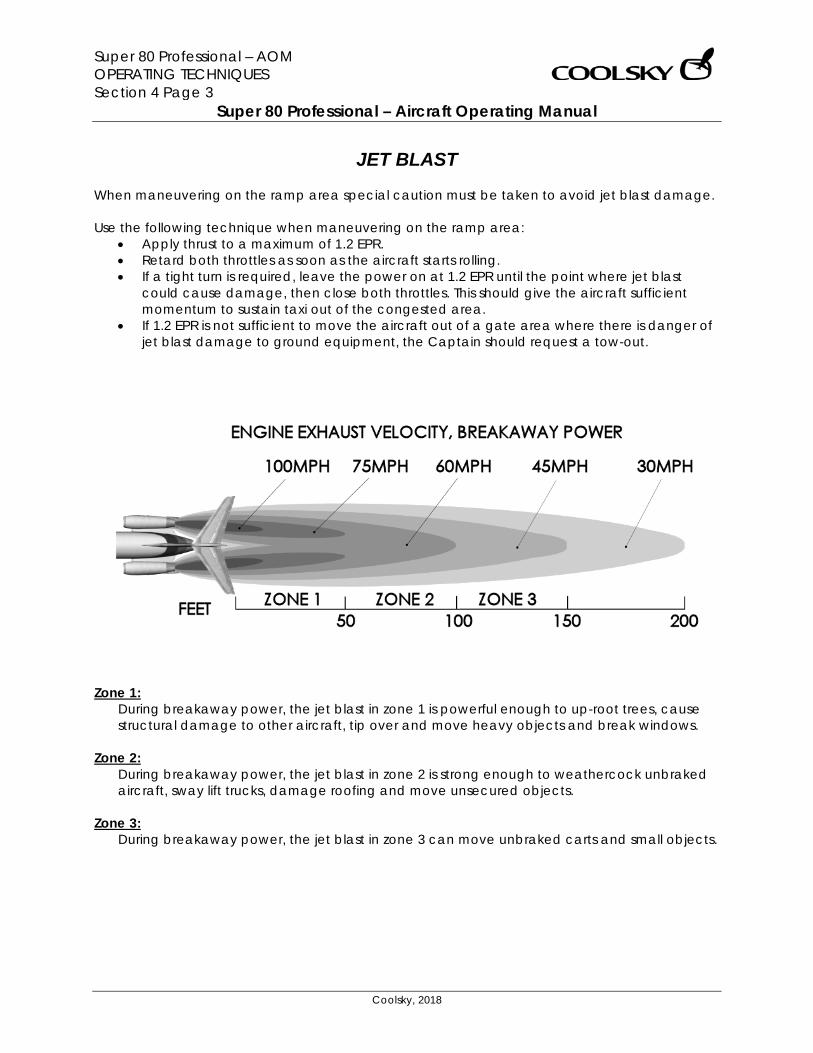
Super 80 Professional – AOM OPERATING TECHNIQUES Section 4 Page 3
Super 80 Professional – Aircraft Operating Manual
Coolsky, 2018
JET BLAST When maneuvering on the ramp area special caution must be taken to avoid jet blast damage. Use the following technique when maneuvering on the ramp area:
• Apply thrust to a maximum of 1.2 EPR. • Retard both throttles as soon as the aircraft starts rolling. • If a tight turn is required, leave the power on at 1.2 EPR until the point where jet blast
could cause damage, then close both throttles. This should give the aircraft sufficient momentum to sustain taxi out of the congested area.
• If 1.2 EPR is not sufficient to move the aircraft out of a gate area where there is danger of jet blast damage to ground equipment, the Captain should request a tow-out.
Zone 1:
During breakaway power, the jet blast in zone 1 is powerful enough to up-root trees, cause structural damage to other aircraft, tip over and move heavy objects and break windows.
Zone 2: During breakaway power, the jet blast in zone 2 is strong enough to weathercock unbraked aircraft, sway lift trucks, damage roofing and move unsecured objects.
Zone 3: During breakaway power, the jet blast in zone 3 can move unbraked carts and small objects.
Super 80 Professional – AOM OPERATING TECHNIQUES Section 4 Page 4
Super 80 Professional – Aircraft Operating Manual
Coolsky, 2018
TAKE-OFF Before Take-off Normally, the Before Take-off checklist is performed while taxiing out to the take-off position. This checklist must be completed before commencing the take-off roll. Runway Alignment On the runway, line up slightly left or right of the center line to avoid the centerline lights. These lights, which are embedded into the runway surface, can cause nose wheel thump during the take-off wheel. When the aircraft is lined up with the runway, check that the heading indication is about the same as the runway number. If a braked take-off is being made, make sure the nose wheel is aligned with the runway prior to releasing the brakes.
Rejected Take-off The braking action provided by the autobrake system in a rejected take-off situation is very sudden and abrupt. Consider using manual braking during a rejected take-off situation if runway length is not critical and immediate maximum braking is not required. Rotation and Initial Climb The take-off and initial climb performance depends on executing the rotation at the correct speed and proper rate. Rotation at VR should be smooth and continuous. Rotating late, slow or under rotating causes the take-off ground run to increase. Wings level should be maintained all the way through rotation and initial climb. Lift off should occur at about 8° deck angle. Note that with the main gear on the ground, the tail cone will strike the runway at a body angle of 10.5°.
CLIMB General On the climbout, make shallow turns and smooth changes in attitude for passenger comfort.
Leveling Off When the autopilot is engaged, closely monitor the FMA to ensure a smooth transition and level-off. Note that adjusting the pitch or vertical speed with the pitch control wheel may disengage the ALT CAP mode and engage VERT SPD mode.
Super 80 Professional – AOM OPERATING TECHNIQUES Section 4 Page 5
Super 80 Professional – Aircraft Operating Manual
Coolsky, 2018
CRUISE Climbing to a Higher Altitude Start a climb to a higher altitude by using the VERT SPD mode or by slowly increasing pitch if hand flying. When the aircraft has reached the desired climb speed, engage IAS/MACH HLD.
Cruise Speed The cruise speed commanded by the FMS is the recommended cruise speed. This speed ensures efficient and economical fuel burn.
DESCENT Descent Speed Above the Mach crossover altitude, descend at the cruise Mach speed. Below the Mach crossover altitude, descend at 280KIAS. Standard Descent Procedure The standard procedure for descent is to descend with a clean aircraft at idle power. If the pilot needs to expedite the descent for traffic reasons, speedbrakes should be used to increase the rate of descent. Descents with flaps/slats extended and/or gear down should be avoided as they are airspeed limited, noisy and expensive. The FMS will present an optimum descent profile with Top of Descent (TD) and End of Descent (ED). ATC and traffic allowing, the pilot should follow the optimized descent plan provided by the FMS. If it becomes necessary to manually calculate the TD/ED, use the following method:
• Determine the altitude difference (total altitude you need to descend)
• 22,000ft • Drop the last three digits • 22,000 → 22 • Multiply by three • 22 x 3 = 66 • For an unrestricted descent to a
landing, add 10 NM. • 66 + 10 = 76 • For a descent to an intermediate
lower altitude, no additive is required.
• Add 2 NM for every 10 knots of tailwind and subtract 2 NM for every 10 knots of headwind.
• 30 knots tailwind • 76 + (3 x 2) = 82 • Our TD is approximately 82NM away
from our landing destination or ED. Cabin Pressurization During Descent A 3° descent profile will help maintain a 300fpm cabin rate of descent. Multiply the ground speed by six to find the required vertical speed required to maintain a 3° descent profile.
Super 80 Professional – AOM OPERATING TECHNIQUES Section 4 Page 6
Super 80 Professional – Aircraft Operating Manual
Coolsky, 2018
HOLDINGFuel Economy When ordered to enter a holding pattern by ATC, maintain the highest possible altitude to lower fuel consumption. If prolonged holding is expected, request ATC to increase the size of the holding pattern. This will reduce the number of turns required. Turns require increased power and increased fuel burn. All holding should be flown with a clean configuration. For best fuel economy, use the speeds in the holding pattern speed chart. However, the pilot should always comply with the ATC minimum holding speed.
Super 80 Professional – AOM OPERATING TECHNIQUES Section 4 Page 7
Super 80 Professional – Aircraft Operating Manual
Coolsky, 2018
APPROACH AND LANDING Visual Approach Be alert for the following visual illusions when executing a visual approach: Runway Slope
An up-sloping runway creates an illusion of being high on the approach. A down-sloping runway creates the illusion of being low on the approach.
Visibility Rain, haze, dust, smoke, glare or darkness may cause the illusion of being too high on the approach.
Runway Lighting Strong, bright runway lights appear to be closer while dim runway lights appear to be farther away.
Runway Dimensions The width versus length ratio of the runway will also affect visual perspective.
Glide Path The normal approach path is based on a 3° descent flight path. Once established on the approach, make small adjustments to the glideslope, approach speed and trim. The approach style is essentially the same for VFR and IFR. Use the 1000 foot point on the runway as aim for the approach. This will ensure that the approach will not be short or unnecessarily long. The landing distance is affected by the glide path as well as the height above the runway threshold. For example, crossing the threshold at 100 feet instead of 50 can increase the landing distance by up to 950 feet on a 3° glide slope. A glide slope of 1° can increase the landing distance by up to 1500 feet.
Use the ILS or VASI to help you establish the correct glide path on the approach. Thrust on Approach Use the throttles as a primary flight control on approach. Use the throttles in coordination with the elevators to control airspeed, rate of descent and position on glide path. Always keep one hand on the throttles, even when using the autothrottle system. Note that in the event of a go-around, the JT8D engines need about 8 seconds to accelerate from approach idle to go-around power. Final Approach A good rule of thumb on final approach to give a 3° glide path: One-half the ground speed (knots) times ten will give the required rate of descent. For example GS= 100, (100 / 2) x 10 = 500fpm Another good rule of thumb: For a 3° glide path maintain 300 feet of altitude for each mile from the touchdown. For example: If you are 5 miles from touchdown, 5 x 300 = 1500 feet. You should be at 1500 feet altitude when 5 miles from touchdown.
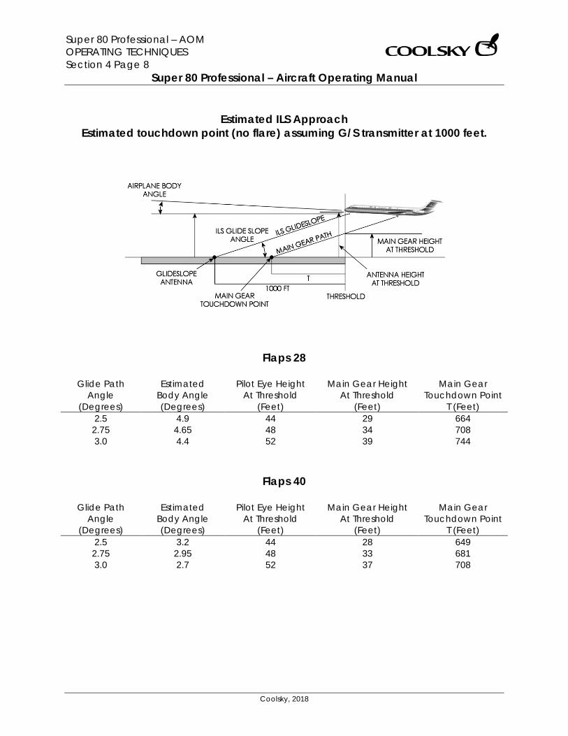
Super 80 Professional – AOM OPERATING TECHNIQUES Section 4 Page 8
Super 80 Professional – Aircraft Operating Manual
Coolsky, 2018
Estimated ILS Approach
Estimated touchdown point (no flare) assuming G/S transmitter at 1000 feet.
Flaps 28
Glide Path Angle
(Degrees)
Estimated Body Angle (Degrees)
Pilot Eye Height At Threshold
(Feet)
Main Gear Height At Threshold
(Feet)
Main Gear Touchdown Point
T (Feet) 2.5 4.9 44 29 664
2.75 4.65 48 34 708 3.0 4.4 52 39 744
Flaps 40
Glide Path Angle
(Degrees)
Estimated Body Angle (Degrees)
Pilot Eye Height At Threshold
(Feet)
Main Gear Height At Threshold
(Feet)
Main Gear Touchdown Point
T (Feet) 2.5 3.2 44 28 649
2.75 2.95 48 33 681 3.0 2.7 52 37 708
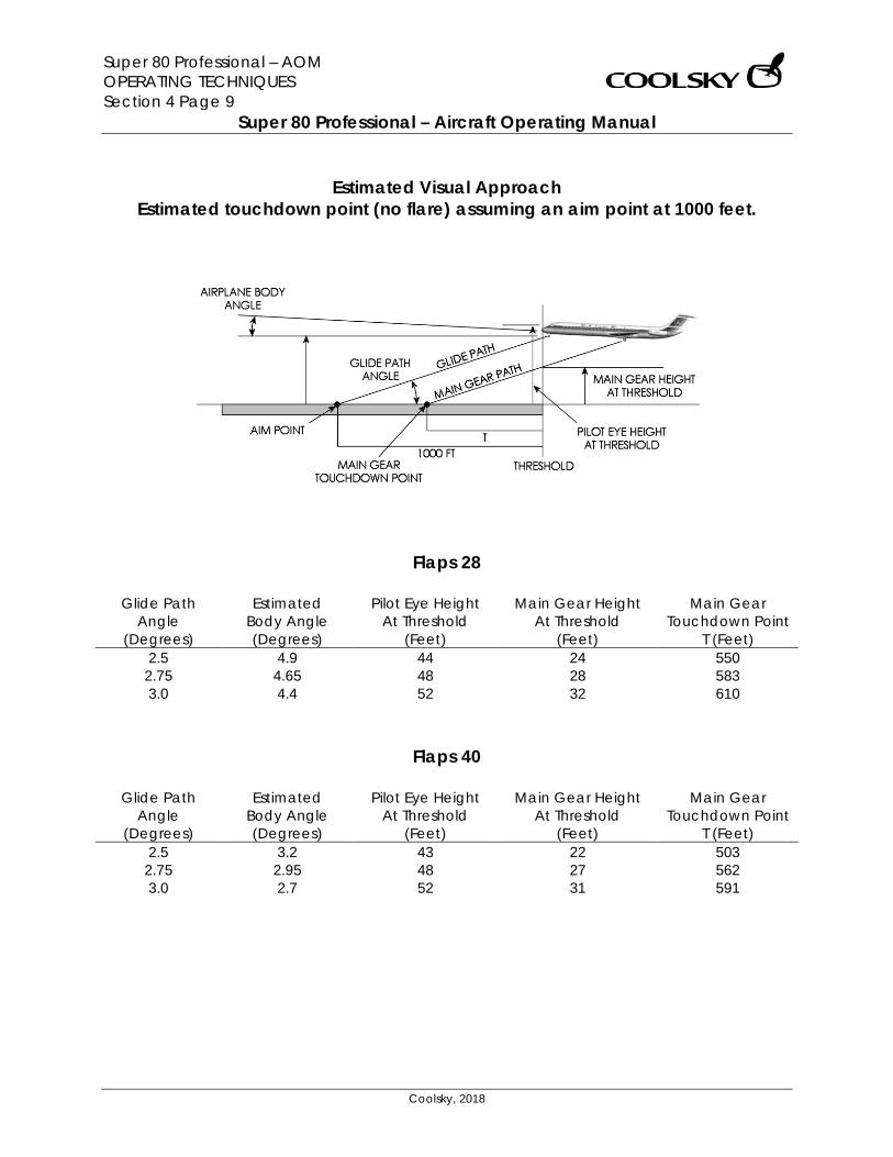
Super 80 Professional – AOM OPERATING TECHNIQUES Section 4 Page 9
Super 80 Professional – Aircraft Operating Manual
Coolsky, 2018
Estimated Visual Approach
Estimated touchdown point (no flare) assuming an aim point at 1000 feet.
Flaps 28
Glide Path Angle
(Degrees)
Estimated Body Angle (Degrees)
Pilot Eye Height At Threshold
(Feet)
Main Gear Height At Threshold
(Feet)
Main Gear Touchdown Point
T (Feet) 2.5 4.9 44 24 550
2.75 4.65 48 28 583 3.0 4.4 52 32 610
Flaps 40
Glide Path Angle
(Degrees)
Estimated Body Angle (Degrees)
Pilot Eye Height At Threshold
(Feet)
Main Gear Height At Threshold
(Feet)
Main Gear Touchdown Point
T (Feet) 2.5 3.2 43 22 503
2.75 2.95 48 27 562 3.0 2.7 52 31 591
Super 80 Professional – AOM OPERATING TECHNIQUES Section 4 Page 10
Super 80 Professional – Aircraft Operating Manual
Coolsky, 2018
Touchdown The descent rate for a normal landing configuration is about 650 to 850 fpm. Recommended landing technique is to reduce the sink rate at approximately 50 feet radio altitude. Smoothly lift the nose 2-3 degrees up to reduce the rate of descent. Simultaneously, slowly reduce power to idle. Do not attempt to hold the aircraft off the runway by further increase in pitch. Thrust should reach idle power at touchdown. With proper airspeed and thrust management, touchdown should occur at VREF, but never below VREF. The aircraft tends to float in ground effect if the flare and thrust are excessive. Floating before touchdown “eats up” a lot of runway. It is better to put the aircraft down on the runway if you are coming in to fast, than trying to bleed the speed off in the air. The aircraft decelerates three times faster on the runway than in the air. It is important to lower the nose on touchdown and hold a positive forward pressure on the control column. This decreases the wing angle of attack, reduces the lift, and puts more weight on the main gear. This increases rolling friction, as well as braking effectiveness. This procedure is five times more effective than holding the nose off for aerodynamic braking.
Directional Control Differential braking may be used to aid in directional control after touchdown. Nose wheel steering should not be used until the aircraft is ready to turn off the runway. Reverse Thrust Reverse thrust should be applied immediately upon touchdown, as reverse thrust is most efficient at higher airspeeds. Early application of reverse thrust greatly reduces runway required for rollout, and greatly reduces brake temperature and wear. The application of reverse thrust tends to reduce and blank out the effect of the rudder. At 90 knots and 1.6 EPR, the rudder is almost completely ineffective. Immediately reduce reverse thrust to idle reverse if the aircraft starts drifting across the runway. This will restore rudder effectiveness and help regain directional control. Use of asymmetrical forward thrust to regain directional control is allowed. Use of asymmetrical reverse thrust is not allowed. Speed Brakes The automatic brake system is inhibited until the spoilers are deployed (manually or automatically). Monitor the automatic deployment of the spoilers at touchdown. Manually apply the spoilers if they fail to deploy automatically.
Super 80 Professional – AOM OPERATING TECHNIQUES Section 4 Page 11
Super 80 Professional – Aircraft Operating Manual
Coolsky, 2018
Autobrakes The autobrake system senses deceleration and modulates the brake pressure required accordingly. Early and effective application of spoilers and reverse thrust is therefore very important to minimize brake temperature and wear. If only minimum reverse thrust is used, the brake energy required to stop the aircraft almost doubles. Brakes The brakes slow down the aircraft by absorbing the motion energy of the aircraft. The brakes convert this motion energy into heat, which is dissipated through cooling. The brakes are required to absorb vast amounts of energy. The higher the speed is at the time the brakes are applied, the higher the amount of energy they have to absorb. While reverse thrust is more effective at higher airspeeds, the brakes are more effective at lower airspeeds. During a normal landing, as speed is being reduced, the brakes should be applied just prior to the termination of reverse thrust operation. This practice will result in the most economical landing performance.
Super 80 Professional – AOM EMERGENCY PROCEDURES Section 5 Page 0
Super 80 Professional – Aircraft Operating Manual
Coolsky, 2018
SECTION 5
EMERGENCY PROCEDURES

Super 80 Professional – AOM EMERGENCY PROCEDURES Section 5 Page 1
Super 80 Professional – Aircraft Operating Manual
Coolsky, 2018
Emergency techniques are currently not described.
Super 80 Professional – AOM AIR CONDITIONING AND PRESSURIZATION Section 6 Page 0
Super 80 Professional – Aircraft Operating Manual
Coolsky, 2018
SECTION 6
AIR CONDITIONING AND PRESSURIZATION
Super 80 Professional – AOM AIR CONDITIONING AND PRESSURIZATION Section 6 Page 1
Super 80 Professional – Aircraft Operating Manual
Coolsky, 2018
TABLE OF CONTENTS
SECTION 6: AIR CONDITIONING AND PRESSURIZATION 0
TABLE OF CONTENTS ................................................................................................................. 1 GENERAL .................................................................................................................................... 2 FUNCTIONAL SCHEMATIC - PNEUMATICS .............................................................................. 3 CONTROLS AND INDICATORS ................................................................................................. 4 AIR CONDITIONING .................................................................................................................. 5 PRESSURIZATION ........................................................................................................................ 7 WARNING AND CAUTION INDICATORS ................................................................................. 9
Super 80 Professional – AOM AIR CONDITIONING AND PRESSURIZATION Section 6 Page 2
Super 80 Professional – Aircraft Operating Manual
Coolsky, 2018
GENERAL Pneumatics The pneumatic system provides pressurized air for cabin pressurization. Air conditioning, ice protection, engine starting, and potable water tank pressurization. For ground operation and engine starting, pneumatic pressure is supplied by the APU, by ground power equipment, or by an operating engine. In flight pneumatic pressure is supplied by the low and/or high stage compressors of both engines. Normally, bleed air from the left and right engines is supplied to the respective air conditioning units. Bleed air from both engines is supplied to the ice protection systems simultaneously. Pneumatic crossfeed valves permit operation of the air conditioning system and ice protection systems from either engine. APU bleed air is normally used only for engine starting and for ground air conditioning when the engines are not operating. Air Conditioning Pressurized air from the pneumatic system is used for air conditioning and for pressurizing the airplane. During ground operation, pneumatic air to operate the air conditioning systems can be obtained from a ground source connected to the airplane, by the auxiliary power unit (APU), or by the engines. During flight, only the engines supply bleed air for operating the air condition. The airplane has two identical air conditioning systems, designed for independent or parallel operation.
Normally the right system operates from the right engine bleed air and supplies the passenger compartment temperature requirements. The left system operates from the left engine bleed air and supplies the flight compartment temperature requirements. Pressurization Pressurization is provided by a controlled flow of bleed air from the pneumatic supply, which passes through the air conditioning systems and is then ducted to the pressurized areas. Desired pressurization levels are maintained by regulating escape of the compressed air through the cabin air outflow valve. Normally, the outflow valve is automatically positioned by a dual automatic pressurization system to control cabin pressure rates from take-off to landing. Dual pressure relief valves are installed to protect the airplane structure from maximum input pressure. The relief valves prevent the cabin differential pressure from exceeding the maximum limit of 8.32 PSI. Negative pressure is relieved by the inward movement of the galley service and passenger entrance door seals, and one negative pressure relief valve installed in the aft pressure bulkhead. When operating on the pressure schedule, the cabin rate of climb will be proportional to the airplane rate of climb, with maximum limits as set by the rate limit knob. When climbing or descending toward a selected altitude above schedule, the cabin rate of change will be as selected on the rate limit knob. With the knob at the index mark, the rate limit is normally 700 fpm climb and 300 fpm descent.
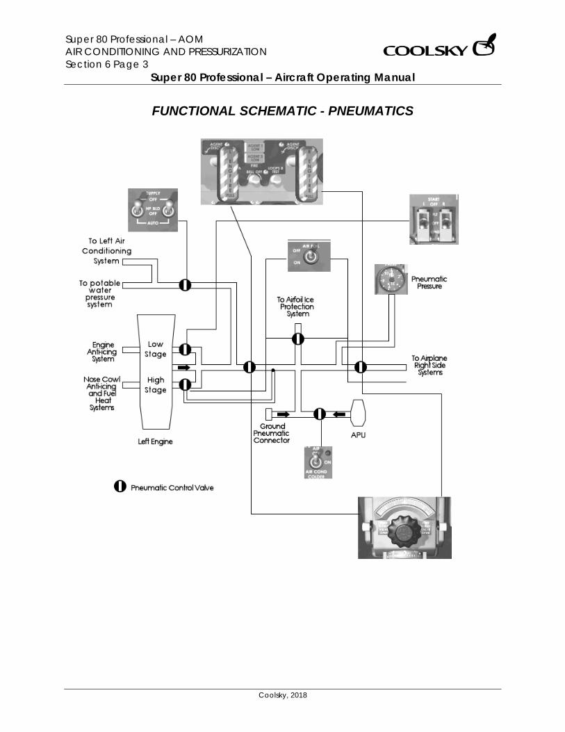
Super 80 Professional – AOM AIR CONDITIONING AND PRESSURIZATION Section 6 Page 3
Super 80 Professional – Aircraft Operating Manual
Coolsky, 2018
FUNCTIONAL SCHEMATIC - PNEUMATICS

Super 80 Professional – AOM AIR CONDITIONING AND PRESSURIZATION Section 6 Page 4
Super 80 Professional – Aircraft Operating Manual
Coolsky, 2018
CONTROLS AND INDICATORS
1. PNEUMATIC PRESSURE GAUGE Indicates pneumatic pressure in the crossfeed manifold. 2. PNEUMATIC X-FEED VALVE LEVER Open (Up) Supplies bleed air for air foil
ice protection (in flight only), for operating both air conditioning packs from one operating engine, and for making pneumatic crossfeed starts from opposite operating engine. Also, on the ground, supplies APU bleed air or air from pneumatic ground source for operating one or both air conditioning packs or for engine starting.
Closed (Down) Shuts off engine bleed air
for air foil ice protection and pneumatic crossfeed starts, and each air conditioning pack is supplied engine bleed air from its respective engine only. On the ground, APU bleed air or air from pneumatic ground source is shutoff and not available for air conditioning packs or engine starts.
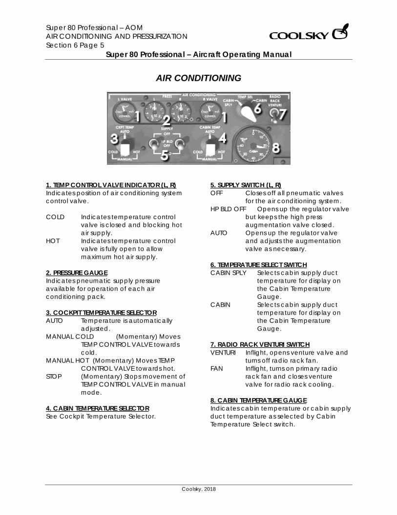
Super 80 Professional – AOM AIR CONDITIONING AND PRESSURIZATION Section 6 Page 5
Super 80 Professional – Aircraft Operating Manual
Coolsky, 2018
AIR CONDITIONING
1. TEMP CONTROL VALVE INDICATOR (L, R) Indicates position of air conditioning system control valve. COLD Indicates temperature control
valve is closed and blocking hot air supply.
HOT Indicates temperature control valve is fully open to allow maximum hot air supply.
2. PRESSURE GAUGE Indicates pneumatic supply pressure available for operation of each air conditioning pack. 3. COCKPIT TEMPERATURE SELECTOR AUTO Temperature is automatically
adjusted. MANUAL COLD (Momentary) Moves
TEMP CONTROL VALVE towards cold.
MANUAL HOT (Momentary) Moves TEMP CONTROL VALVE towards hot.
STOP (Momentary) Stops movement of TEMP CONTROL VALVE in manual mode.
4. CABIN TEMPERATURE SELECTOR See Cockpit Temperature Selector.
5. SUPPLY SWITCH (L, R) OFF Closes off all pneumatic valves
for the air conditioning system. HP BLD OFF Opens up the regulator valve
but keeps the high press augmentation valve closed.
AUTO Opens up the regulator valve and adjusts the augmentation valve as necessary.
6. TEMPERATURE SELECT SWITCH CABIN SPLY Selects cabin supply duct
temperature for display on the Cabin Temperature Gauge.
CABIN Selects cabin supply duct temperature for display on the Cabin Temperature Gauge.
7. RADIO RACK VENTURI SWITCH VENTURI Inflight, opens venture valve and
turns off radio rack fan. FAN Inflight, turns on primary radio
rack fan and closes venture valve for radio rack cooling.
8. CABIN TEMPERATURE GAUGE Indicates cabin temperature or cabin supply duct temperature as selected by Cabin Temperature Select switch.
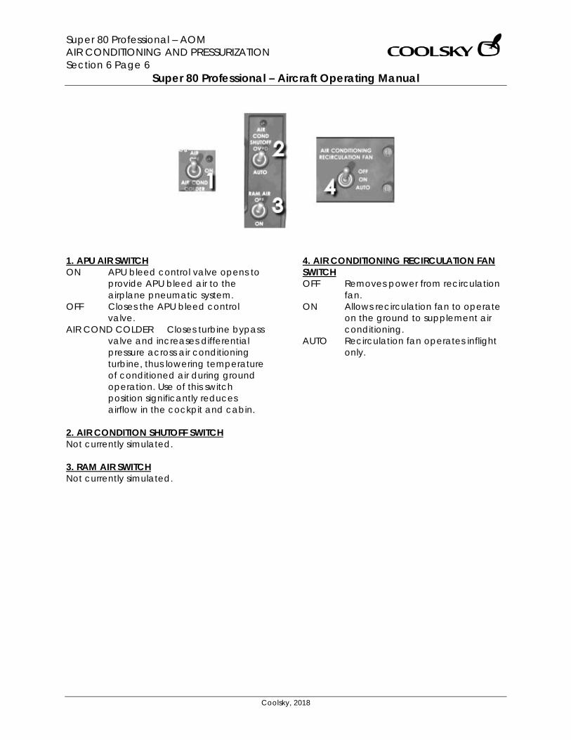
Super 80 Professional – AOM AIR CONDITIONING AND PRESSURIZATION Section 6 Page 6
Super 80 Professional – Aircraft Operating Manual
Coolsky, 2018
1. APU AIR SWITCH ON APU bleed control valve opens to
provide APU bleed air to the airplane pneumatic system.
OFF Closes the APU bleed control valve.
AIR COND COLDER Closes turbine bypass valve and increases differential pressure across air conditioning turbine, thus lowering temperature of conditioned air during ground operation. Use of this switch position significantly reduces airflow in the cockpit and cabin.
2. AIR CONDITION SHUTOFF SWITCH Not currently simulated. 3. RAM AIR SWITCH Not currently simulated.
4. AIR CONDITIONING RECIRCULATION FAN SWITCH OFF Removes power from recirculation
fan. ON Allows recirculation fan to operate
on the ground to supplement air conditioning.
AUTO Recirculation fan operates inflight only.
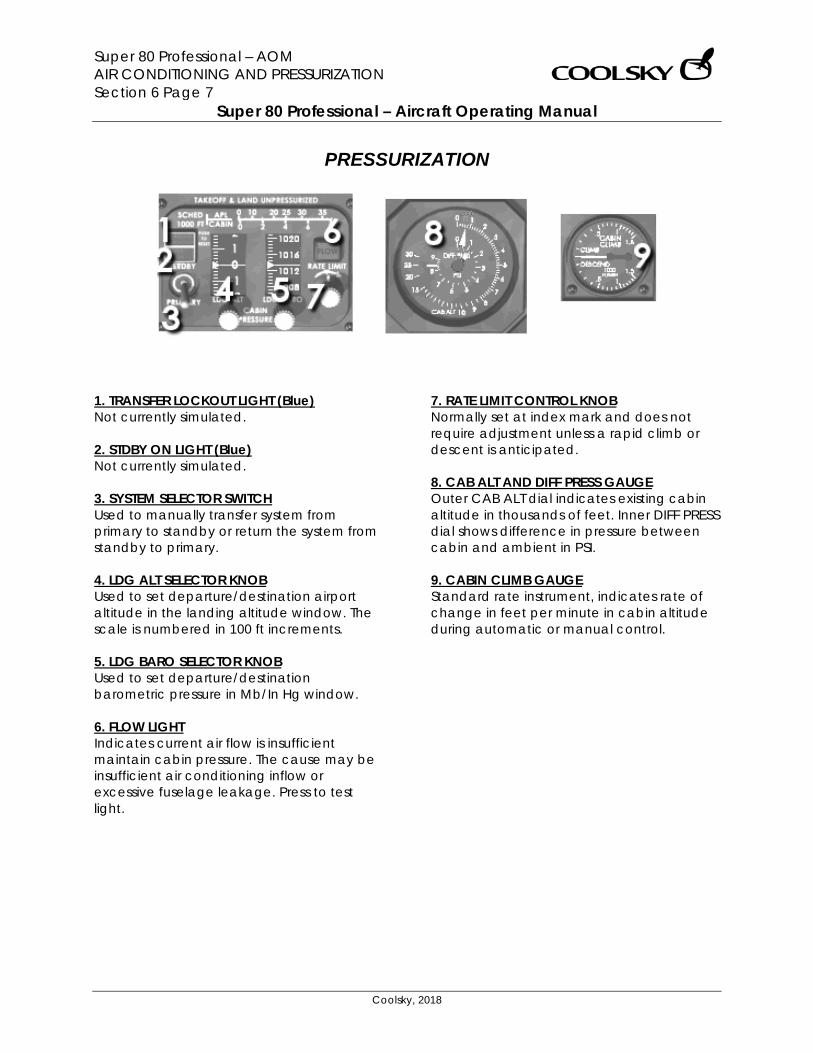
Super 80 Professional – AOM AIR CONDITIONING AND PRESSURIZATION Section 6 Page 7
Super 80 Professional – Aircraft Operating Manual
Coolsky, 2018
PRESSURIZATION
1. TRANSFER LOCKOUT LIGHT (Blue) Not currently simulated. 2. STDBY ON LIGHT (Blue) Not currently simulated. 3. SYSTEM SELECTOR SWITCH Used to manually transfer system from primary to standby or return the system from standby to primary. 4. LDG ALT SELECTOR KNOB Used to set departure/destination airport altitude in the landing altitude window. The scale is numbered in 100 ft increments. 5. LDG BARO SELECTOR KNOB Used to set departure/destination barometric pressure in Mb/In Hg window. 6. FLOW LIGHT Indicates current air flow is insufficient maintain cabin pressure. The cause may be insufficient air conditioning inflow or excessive fuselage leakage. Press to test light.
7. RATE LIMIT CONTROL KNOB Normally set at index mark and does not require adjustment unless a rapid climb or descent is anticipated. 8. CAB ALT AND DIFF PRESS GAUGE Outer CAB ALT dial indicates existing cabin altitude in thousands of feet. Inner DIFF PRESS dial shows difference in pressure between cabin and ambient in PSI. 9. CABIN CLIMB GAUGE Standard rate instrument, indicates rate of change in feet per minute in cabin altitude during automatic or manual control.
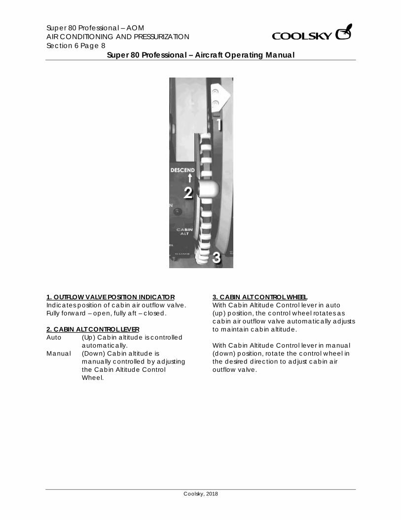
Super 80 Professional – AOM AIR CONDITIONING AND PRESSURIZATION Section 6 Page 8
Super 80 Professional – Aircraft Operating Manual
Coolsky, 2018
1. OUTFLOW VALVE POSITION INDICATOR Indicates position of cabin air outflow valve. Fully forward – open, fully aft – closed. 2. CABIN ALT CONTROL LEVER Auto (Up) Cabin altitude is controlled
automatically. Manual (Down) Cabin altitude is
manually controlled by adjusting the Cabin Altitude Control Wheel.
3. CABIN ALT CONTROL WHEEL With Cabin Altitude Control lever in auto (up) position, the control wheel rotates as cabin air outflow valve automatically adjusts to maintain cabin altitude. With Cabin Altitude Control lever in manual (down) position, rotate the control wheel in the desired direction to adjust cabin air outflow valve.
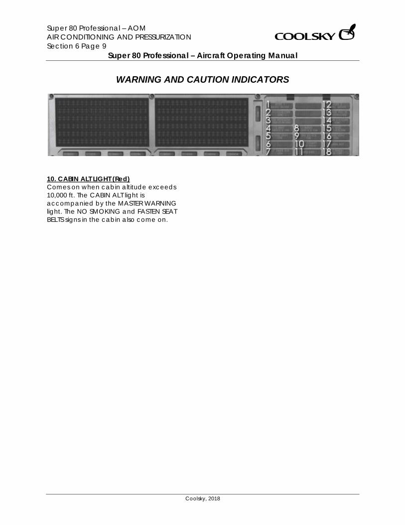
Super 80 Professional – AOM AIR CONDITIONING AND PRESSURIZATION Section 6 Page 9
Super 80 Professional – Aircraft Operating Manual
Coolsky, 2018
WARNING AND CAUTION INDICATORS
10. CABIN ALT LIGHT (Red) Comes on when cabin altitude exceeds 10,000 ft. The CABIN ALT light is accompanied by the MASTER WARNING light. The NO SMOKING and FASTEN SEAT BELTS signs in the cabin also come on.
Super 80 Professional – AOM ANTI-ICE AND RAIN PROTECTION Section 7 Page 0
Super 80 Professional – Aircraft Operating Manual
Coolsky, 2018
SECTION 7
ANTI-ICE AND RAIN PROTECTION
Super 80 Professional – AOM ANTI-ICE AND RAIN PROTECTION Section 7 Page 1
Super 80 Professional – Aircraft Operating Manual
Coolsky, 2018
TABLE OF CONTENTS
SECTION 7: ANTI-ICE AND RAIN PROTECTION 0
TABLE OF CONTENTS ................................................................................................................. 1 GENERAL .................................................................................................................................... 2 CONTROLS AND INDICATORS ................................................................................................. 3 WARNING AND CAUTION IND .................................................................................................. 5
Super 80 Professional – AOM ANTI-ICE AND RAIN PROTECTION Section 7 Page 2
Super 80 Professional – Aircraft Operating Manual
Coolsky, 2018
GENERAL General The airplane ice protection systems employ hot air and electrical heating for anti-icing and anti-fogging functions. Rain removal is accomplished by chemical repellent and electrically operated windshield wipers. Window Heat Electrical heating provides heat for anti-icing and anti-fogging of the pilot’s three windshields, and anti-fogging for the clearview and overhead windows. Probe Heat Electrical heating is used for anti-icing the pitot tubes, static port areas, stall angle of attack vanes, and ram air temperature probe. Airfoil Ice Protection The airfoil ice protection system provides anti-icing heat to the wing leading edge slats, forward strakes, and to the air conditioning ram air-scoop inlet in flight, when the air foil switch and associated pneumatic crossfeed valves are actuated. De-icing is available for the horizontal stabilizer leading edge by the tail de-ice pushbutton. Heat is then diverted from the wing leading edge slats and strakes to the horizontal stabilizer. Tail de-icing is provided for 2.5 minutes, and then flow is reverted back to the wing slats and strakes again. When air foil anti-icing is selected, tail de-icing will automatically be selected every 15 minutes.
Forward strakes anti-icing is accomplished through the same system as the wing leading edge slats, and is controlled by the same switch. Clear Ice Detectors Triangular decals, with a piece of parachute cord attached, are installed on the upper inboard surface of both wings. The purpose of these decals is to assist the de-icing crew during de-icing. If clear ice is present the cords will remain frozen to the wing. De-icing fluid should be applied until the cords move freely. The triangles provide a secondary visual reference as the edges of the triangle will appear irregular if covered with clear ice. Engine Anti-Ice Engine anti-icing is provided by independent system, controlled by individual switches located on the overhead ice protection panel. Each engine provides ice protection for the respective engine, nose cowl, inlet bullet, and compressor inlet guide vanes.
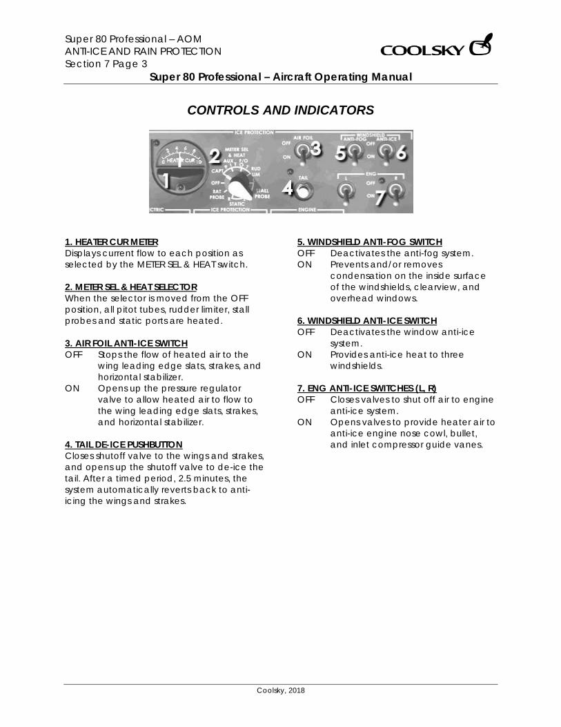
Super 80 Professional – AOM ANTI-ICE AND RAIN PROTECTION Section 7 Page 3
Super 80 Professional – Aircraft Operating Manual
Coolsky, 2018
CONTROLS AND INDICATORS
1. HEATER CUR METER Displays current flow to each position as selected by the METER SEL & HEAT switch. 2. METER SEL & HEAT SELECTOR When the selector is moved from the OFF position, all pitot tubes, rudder limiter, stall probes and static ports are heated. 3. AIR FOIL ANTI-ICE SWITCH OFF Stops the flow of heated air to the
wing leading edge slats, strakes, and horizontal stabilizer.
ON Opens up the pressure regulator valve to allow heated air to flow to the wing leading edge slats, strakes, and horizontal stabilizer.
4. TAIL DE-ICE PUSHBUTTON Closes shutoff valve to the wings and strakes, and opens up the shutoff valve to de-ice the tail. After a timed period, 2.5 minutes, the system automatically reverts back to anti-icing the wings and strakes.
5. WINDSHIELD ANTI-FOG SWITCH OFF Deactivates the anti-fog system. ON Prevents and/or removes
condensation on the inside surface of the windshields, clearview, and overhead windows.
6. WINDSHIELD ANTI-ICE SWITCH OFF Deactivates the window anti-ice
system. ON Provides anti-ice heat to three
windshields. 7. ENG ANTI-ICE SWITCHES (L, R) OFF Closes valves to shut off air to engine
anti-ice system. ON Opens valves to provide heater air to
anti-ice engine nose cowl, bullet, and inlet compressor guide vanes.
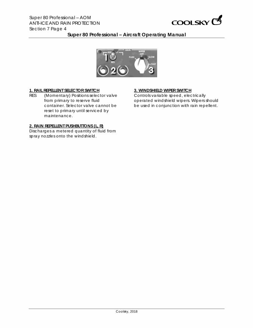
Super 80 Professional – AOM ANTI-ICE AND RAIN PROTECTION Section 7 Page 4
Super 80 Professional – Aircraft Operating Manual
Coolsky, 2018
1. RAIL REPELLENT SELECTOR SWITCH RES (Momentary) Positions selector valve
from primary to reserve fluid container. Selector valve cannot be reset to primary until serviced by maintenance.
2. RAIN REPELLENT PUSHBUTTONS (L, R) Discharges a metered quantity of fluid from spray nozzles onto the windshield.
3. WINDSHIELD WIPER SWITCH Controls variable speed, electrically operated windshield wipers. Wipers should be used in conjunction with rain repellent.

Super 80 Professional – AOM ANTI-ICE AND RAIN PROTECTION Section 7 Page 5
Super 80 Professional – Aircraft Operating Manual
Coolsky, 2018
WARNING AND CAUTION INDICATORS
4 & 15. ENG ANTI-ICE ON LIGHTS (L, R)(Blue) Indicates engine anti-ice system is on. 8. WING ANTI-ICE ON LIGHT (Blue) Indicates anti-ice heat has been selected for wing leading edge and strakes. 9. TAIL DE-ICE ON LIGHT (Blue) Indicates de-ice heat has been selected for the leading edge of the horizontal stabilizer.
PITOT/STALL HEATER OFF LIGHT (Digital display) Comes on to indicate METER SEL & HEATER selector in OFF. MASTER CAUTION light also comes on. 3. RAIN REPELLENT RESERVE IN USE LIGHT (Blue) Indicates reserve fluid container has been selected.
Super 80 Professional – AOM AUTO-FLIGHT Section 8 Page 0
Super 80 Professional – Aircraft Operating Manual
Coolsky, 2018
SECTION 8
AUTO-FLIGHT
Super 80 Professional – AOM AUTO-FLIGHT Section 8 Page 1
Super 80 Professional – Aircraft Operating Manual
Coolsky, 2018
TABLE OF CONTENTS
SECTION 8: AUTO-FLIGHT 0
TABLE OF CONTENTS ................................................................................................................. 1 GENERAL .................................................................................................................................... 2 FLIGHT DIRECTOR ...................................................................................................................... 5 AUTOTHROTTLE .......................................................................................................................... 6 ROLL MODE SELECTORS ........................................................................................................... 7 PITCH MODE SELECTORS .......................................................................................................... 8 YAW DAMPER, MACH TRIM AND ALTITUDE ADVISORY LIGHT........................................... 10 EFIS CONTROLS ........................................................................................................................ 11
EFIS CONTROL AND DIMMING PANEL (2) ..................................................................... 11 EFIS SWITCHING PANEL .................................................................................................... 11
FLIGHT MODE ANNUNCIATOR .............................................................................................. 12 FMA – LEGEND LIGHTS ............................................................................................................ 13 FMA – AUTOTHROTTLE WINDOW ........................................................................................... 14 FMA – ARM WINDOW ............................................................................................................. 16 FMA – ROLL WINDOW ............................................................................................................. 17 FMA – PITCH WINDOW ........................................................................................................... 19
Super 80 Professional – AOM AUTO-FLIGHT Section 8 Page 2
Super 80 Professional – Aircraft Operating Manual
Coolsky, 2018
GENERAL General The aircraft is equipped with two digital flight guidance computers (DFGC 1 and 2). Each DFGC operates independently of each other. The flight crew selects the operating DFGC with the 1-2 Selector on the Flight Guidance Control Panel. The 1-2 Selector is normally set to the side of the flying pilot. This allows the flying pilot’s navigation radio to be connected to the operating DFGC and therefore to the autopilot. Each DFGC received input data from IRS 1 and 2 respectively. Flight Mode Annunciator Flight Mode Annunciators (FMA) are provided for the Captain and F/O. The FMA displays the armed or engaged modes of the Digital Flight Guidance System. The FMA provides legend displays for the Instrument Comparator, disengage lights for the autopilot and autothrottle, and four windows for the Flight Guidance Modes. Autopilot The AP function, in conjunction with the yaw damper function, automatically controls the airplane in pitch, roll and yaw maneuvering axes. The AP will actuate the appropriate control surfaces to control the aircraft for the selected AP mode of operation.
The AP modes of operation will automatically control the aircraft for the following maneuvers:
• maintain an existing altitude • descend or climb to and maintain a
preselected altitude • maintain a selected vertical speed,
indicated airspeed, or mach number • maintain an existing heading • fly to and maintain a preselected
heading • fly to, capture, and track a selected
VOR or localizer course • capture and track a glideslope • runway alignment and flare for
automatic landing. The AP warning light on the FMA will come on if the AP disengages for any reason. Flight Director The FD function provides visual guidance commands to fly the aircraft manually or to visually monitor AP response to the guidance commands. Pitch (including speed control) and roll guidance from the DFGC are displayed on the Primary Flight Display (PFD). FD command bars on the PFD directs the pilot to turn, climb, or descend. A fast/slow indicator on the PFD reflects airplane speed in relation to selected speed on the FGCP or computed safe speed above stall (ALFA speed).
Super 80 Professional – AOM AUTO-FLIGHT Section 8 Page 3
Super 80 Professional – Aircraft Operating Manual
Coolsky, 2018
Speed control With the speed control function active the aircraft will pitch up/down to lose/gain speed. Speed control inputs for attitude control are displayed by the FD command bars and fast/slow indicator on the PFD. IAS Hold mode and Mach Hold mode are available. IAS and Mach Hold mode are used during climb and descent to maintain a constant airspeed. During take-off mode of operation, the FD command bars on the PFD will command a pitch attitude to maintain V2+10 KIAS for two engine operation. During go-around mode, the FD command bars on the PFD will command the go-around speed, which is the same as landing approach speed. Note: The default P3D TO/GA mode is used for take-off and go-around operation. Autothrottle The autothrottle function automatically positions the throttles to maintain airspeed or engine thrust as required for the operational mode selected. The autothrottle function will control the throttles for the following maneuvers:
• take-off • climb • cruise • holding • approach • flare (not simulated, manually retard
the throttles) • go-around
The autothrottle function is engaged by moving the AUTO THROT switch from OFF to AUTO THROT position. When the autothrottle
function is disengaged the THROTTLE warning light on the FMA will come on. A clutch mechanism permits manual positioning of the throttles without disengaging the autothrottle function. However, the throttles should not be manually positioned, when the ATS is active, except when in CLMP mode or, during descent, when the autothrottle FMA annunciates LOW LIM. Overriding the autothrottle may cause excessive clutch wear requiring extensive down time to replace the autothrottle servo drive assembly. Altitude Advisory System The Altitude Advisory System automatically alerts the crew that the airplane is approaching the preselected altitude or that the airplane is deviating from a previously selected and captured altitude. An advisory light on the altimeters provides the alert for either of the above situations. The advisory light will come on steady when the airplane is 750 feet from the selected altitude. The light will then stay on until the airplane is within 250 feet of the selected altitude. If the airplane deviates from the acquired altitude with more than 250 feet, the advisory light will come on flashing, accompanied by an aural tone alert followed by the spoken word “Altitude”.
Super 80 Professional – AOM AUTO-FLIGHT Section 8 Page 4
Super 80 Professional – Aircraft Operating Manual
Coolsky, 2018
Flight Management System The flight management system (FMS), in conjunction with other interfacing equipment on the aircraft, provides automatic navigation guidance, map display, and in-flight performance optimization. It eliminates many routine tasks and computations normally performed by the flight crew. When coupled to the autopilot, flight director, and auto throttles, the system provides guidance for controlling roll, pitch, and engine thrust.
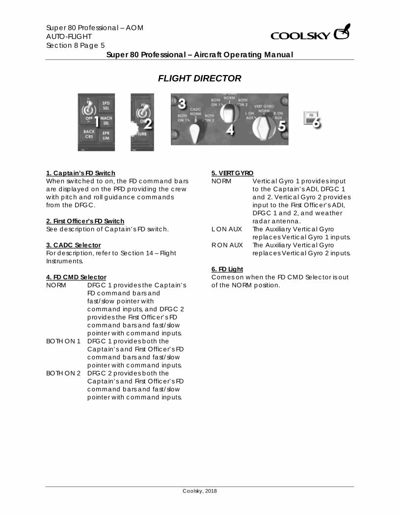
Super 80 Professional – AOM AUTO-FLIGHT Section 8 Page 5
Super 80 Professional – Aircraft Operating Manual
Coolsky, 2018
FLIGHT DIRECTOR
1. Captain’s FD Switch When switched to on, the FD command bars are displayed on the PFD providing the crew with pitch and roll guidance commands from the DFGC. 2. First Officer’s FD Switch See description of Captain’s FD switch. 3. CADC Selector For description, refer to Section 14 – Flight Instruments. 4. FD CMD Selector NORM DFGC 1 provides the Captain’s
FD command bars and fast/slow pointer with command inputs, and DFGC 2 provides the First Officer’s FD command bars and fast/slow pointer with command inputs.
BOTH ON 1 DFGC 1 provides both the Captain’s and First Officer’s FD command bars and fast/slow pointer with command inputs.
BOTH ON 2 DFGC 2 provides both the Captain’s and First Officer’s FD command bars and fast/slow pointer with command inputs.
5. VERT GYRO NORM Vertical Gyro 1 provides input
to the Captain’s ADI, DFGC 1 and 2. Vertical Gyro 2 provides input to the First Officer’s ADI, DFGC 1 and 2, and weather radar antenna.
L ON AUX The Auxiliary Vertical Gyro replaces Vertical Gyro 1 inputs.
R ON AUX The Auxiliary Vertical Gyro replaces Vertical Gyro 2 inputs.
6. FD Light Comes on when the FD CMD Selector is out of the NORM position.
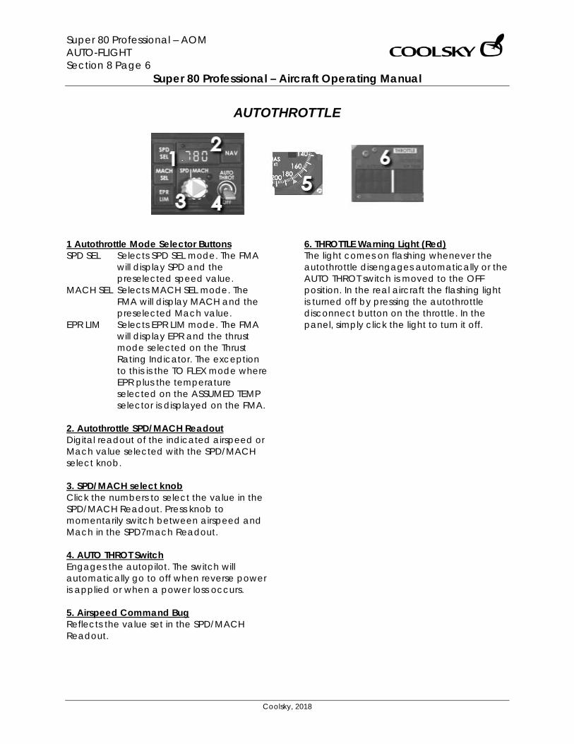
Super 80 Professional – AOM AUTO-FLIGHT Section 8 Page 6
Super 80 Professional – Aircraft Operating Manual
Coolsky, 2018
AUTOTHROTTLE
1 Autothrottle Mode Selector Buttons SPD SEL Selects SPD SEL mode. The FMA
will display SPD and the preselected speed value.
MACH SEL Selects MACH SEL mode. The FMA will display MACH and the preselected Mach value.
EPR LIM Selects EPR LIM mode. The FMA will display EPR and the thrust mode selected on the Thrust Rating Indicator. The exception to this is the TO FLEX mode where EPR plus the temperature selected on the ASSUMED TEMP selector is displayed on the FMA.
2. Autothrottle SPD/MACH Readout Digital readout of the indicated airspeed or Mach value selected with the SPD/MACH select knob. 3. SPD/MACH select knob Click the numbers to select the value in the SPD/MACH Readout. Press knob to momentarily switch between airspeed and Mach in the SPD7mach Readout. 4. AUTO THROT Switch Engages the autopilot. The switch will automatically go to off when reverse power is applied or when a power loss occurs. 5. Airspeed Command Bug Reflects the value set in the SPD/MACH Readout.
6. THROTTLE Warning Light (Red) The light comes on flashing whenever the autothrottle disengages automatically or the AUTO THROT switch is moved to the OFF position. In the real aircraft the flashing light is turned off by pressing the autothrottle disconnect button on the throttle. In the panel, simply click the light to turn it off.
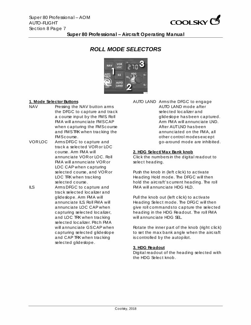
Super 80 Professional – AOM AUTO-FLIGHT Section 8 Page 7
Super 80 Professional – Aircraft Operating Manual
Coolsky, 2018
ROLL MODE SELECTORS
1. Mode Selector Buttons NAV Pressing the NAV button arms
the DFGC to capture and track a course input by the FMS. Roll FMA will annunciate FMS CAP when capturing the FMS course and FMS TRK when tracking the FMS course.
VOR LOC Arms DFGC to capture and track a selected VOR or LOC course. Arm FMA will annunciate VOR or LOC. Roll FMA will annunciate VOR or LOC CAP when capturing selected course, and VOR or LOC TRK when tracking selected course.
ILS Arms DFGC to capture and track selected localizer and glideslope. Arm FMA will annunciate ILS. Roll FMA will annunciate LOC CAP when capturing selected localizer, and LOC TRK when tracking selected localizer. Pitch FMA will annunciate GS CAP when capturing selected glideslope and CAP TRK when tracking selected glideslope.
AUTO LAND Arms the DFGC to engage AUTO LAND mode after selected localizer and glideslope has been captured. Arm FMA will annunciate LND. After AUT LND has been annunciated on the FMA, all other control modes except go-around mode are inhibited.
2. HDG Select/Max Bank knob Click the numbers in the digital readout to select heading. Push the knob in (left click) to activate Heading Hold mode. The DFGC will then hold the aircraft’s current heading. The roll FMA will annunciate HDG HLD. Pull the knob out (left click) to activate Heading Select mode. The DFGC will then give roll commands to capture the selected heading in the HDG Readout. The roll FMA will annunciate HDG SEL. Rotate the inner part of the knob (right click) to set the max bank angle when the aircraft is controlled by the autopilot. 3. HDG Readout Digital readout of the heading selected with the HDG Select knob.
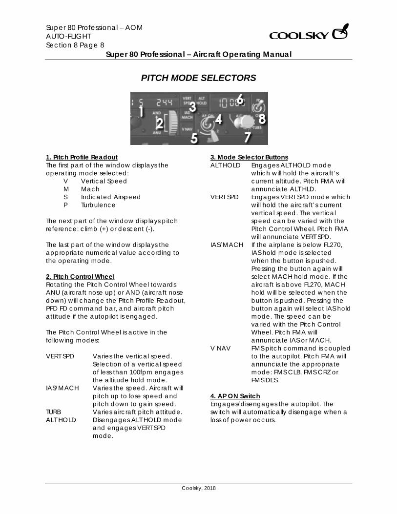
Super 80 Professional – AOM AUTO-FLIGHT Section 8 Page 8
Super 80 Professional – Aircraft Operating Manual
Coolsky, 2018
PITCH MODE SELECTORS
1. Pitch Profile Readout The first part of the window displays the operating mode selected:
V Vertical Speed M Mach S Indicated Airspeed P Turbulence
The next part of the window displays pitch reference: climb (+) or descent (-). The last part of the window displays the appropriate numerical value according to the operating mode. 2. Pitch Control Wheel Rotating the Pitch Control Wheel towards ANU (aircraft nose up) or AND (aircraft nose down) will change the Pitch Profile Readout, PFD FD command bar, and aircraft pitch attitude if the autopilot is engaged. The Pitch Control Wheel is active in the following modes: VERT SPD Varies the vertical speed.
Selection of a vertical speed of less than 100fpm engages the altitude hold mode.
IAS/MACH Varies the speed. Aircraft will pitch up to lose speed and pitch down to gain speed.
TURB Varies aircraft pitch attitude. ALT HOLD Disengages ALT HOLD mode
and engages VERT SPD mode.
3. Mode Selector Buttons ALT HOLD Engages ALT HOLD mode
which will hold the aircraft’s current altitude. Pitch FMA will annunciate ALT HLD.
VERT SPD Engages VERT SPD mode which will hold the aircraft’s current vertical speed. The vertical speed can be varied with the Pitch Control Wheel. Pitch FMA will annunciate VERT SPD.
IAS/MACH If the airplane is below FL270, IAS hold mode is selected when the button is pushed. Pressing the button again will select MACH hold mode. If the aircraft is above FL270, MACH hold will be selected when the button is pushed. Pressing the button again will select IAS hold mode. The speed can be varied with the Pitch Control Wheel. Pitch FMA will annunciate IAS or MACH.
V NAV FMS pitch command is coupled to the autopilot. Pitch FMA will annunciate the appropriate mode: FMS CLB, FMS CRZ or FMS DES.
4. AP ON Switch Engages/disengages the autopilot. The switch will automatically disengage when a loss of power occurs.
Super 80 Professional – AOM AUTO-FLIGHT Section 8 Page 9
Super 80 Professional – Aircraft Operating Manual
Coolsky, 2018
5. DFGC 1 – 2 Switch Selects DFGC 1 or 2 for all flight guidance system functions except FD. Note that if AP and/or ATS are engaged, switching DFGC will cause these to disengage. Also, if the IRS unit supplying the active DFGC with navigation/attitude data is unable to supply the data, the AP master switch will disengage. The other DFGC should be selected if this occurs. 6. ALT Preselect Readout Digital readout of the altitude selected with the ALT Preselect knob. 7. ALT SET Knob Click the digital readout to set the altitude. Pull the knob out to arm capture of the preselected altitude. 8. TURB Mode Button Engaging the TURB mode provides dampened pitch and roll commands from the DFGC. The autothrottle will automatically disengage. Roll FMA will annunciate WNG LVL. Pitch FMA will annunciate TURB.
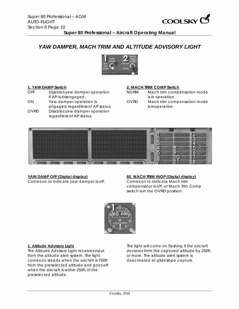
Super 80 Professional – AOM AUTO-FLIGHT Section 8 Page 10
Super 80 Professional – Aircraft Operating Manual
Coolsky, 2018
YAW DAMPER, MACH TRIM AND ALTITUDE ADVISORY LIGHT
1. YAW DAMP Switch OFF Disables yaw damper operation
if AP is disengaged. ON Yaw damper operation is
engaged regardless of AP status. OVRD Disables yaw damper operation
regardless of AP status.
2. MACH TRIM COMP Switch NORM Mach trim compensation mode
is in operation. OVRD Mach trim compensation mode
is inoperative.
YAW DAMP OFF (Digital display) Comes on to indicate yaw damper is off.
60. MACH TRIM INOP (Digital display) Comes on to indicate Mach trim compensator is off, or Mach Trim Comp switch is in the OVRD position.
1. Altitude Advisory Light The Altitude Advisory Light receives input from the altitude alert system. The light comes on steady when the aircraft is 750ft from the preselected altitude and goes off when the aircraft is within 250ft of the preselected altitude.
The light will come on flashing if the aircraft deviates from the captured altitude by 250ft or more. The altitude alert system is deactivated at glideslope capture.
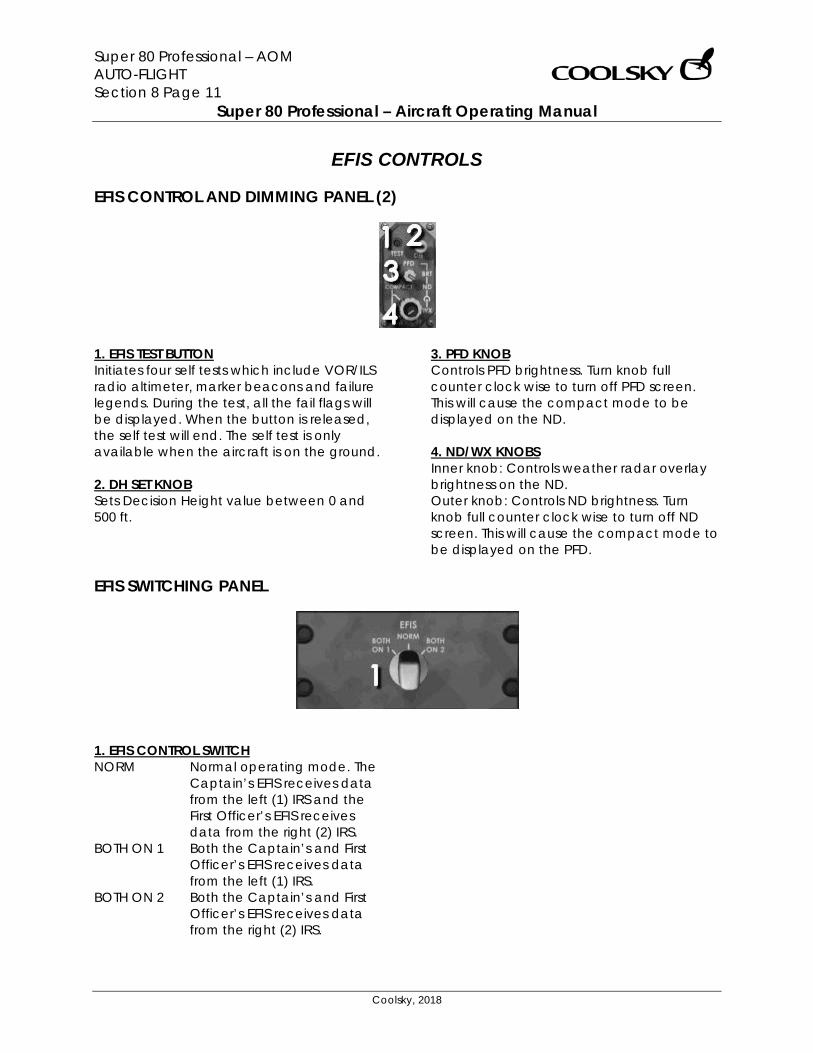
Super 80 Professional – AOM AUTO-FLIGHT Section 8 Page 11
Super 80 Professional – Aircraft Operating Manual
Coolsky, 2018
EFIS CONTROLS
EFIS CONTROL AND DIMMING PANEL (2)
1. EFIS TEST BUTTON Initiates four self tests which include VOR/ILS radio altimeter, marker beacons and failure legends. During the test, all the fail flags will be displayed. When the button is released, the self test will end. The self test is only available when the aircraft is on the ground. 2. DH SET KNOB Sets Decision Height value between 0 and 500 ft.
3. PFD KNOB Controls PFD brightness. Turn knob full counter clock wise to turn off PFD screen. This will cause the compact mode to be displayed on the ND. 4. ND/WX KNOBS Inner knob: Controls weather radar overlay brightness on the ND. Outer knob: Controls ND brightness. Turn knob full counter clock wise to turn off ND screen. This will cause the compact mode to be displayed on the PFD.
EFIS SWITCHING PANEL
1. EFIS CONTROL SWITCH NORM Normal operating mode. The
Captain’s EFIS receives data from the left (1) IRS and the First Officer’s EFIS receives data from the right (2) IRS.
BOTH ON 1 Both the Captain’s and First Officer’s EFIS receives data from the left (1) IRS.
BOTH ON 2 Both the Captain’s and First Officer’s EFIS receives data from the right (2) IRS.
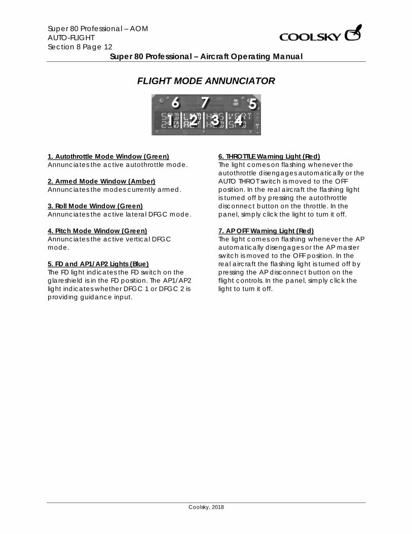
Super 80 Professional – AOM AUTO-FLIGHT Section 8 Page 12
Super 80 Professional – Aircraft Operating Manual
Coolsky, 2018
FLIGHT MODE ANNUNCIATOR
1. Autothrottle Mode Window (Green) Annunciates the active autothrottle mode. 2. Armed Mode Window (Amber) Annunciates the modes currently armed. 3. Roll Mode Window (Green) Annunciates the active lateral DFGC mode. 4. Pitch Mode Window (Green) Annunciates the active vertical DFGC mode. 5. FD and AP1/AP2 Lights (Blue) The FD light indicates the FD switch on the glareshield is in the FD position. The AP1/AP2 light indicates whether DFGC 1 or DFGC 2 is providing guidance input.
6. THROTTLE Warning Light (Red) The light comes on flashing whenever the autothrottle disengages automatically or the AUTO THROT switch is moved to the OFF position. In the real aircraft the flashing light is turned off by pressing the autothrottle disconnect button on the throttle. In the panel, simply click the light to turn it off. 7. AP OFF Warning Light (Red) The light comes on flashing whenever the AP automatically disengages or the AP master switch is moved to the OFF position. In the real aircraft the flashing light is turned off by pressing the AP disconnect button on the flight controls. In the panel, simply click the light to turn it off.
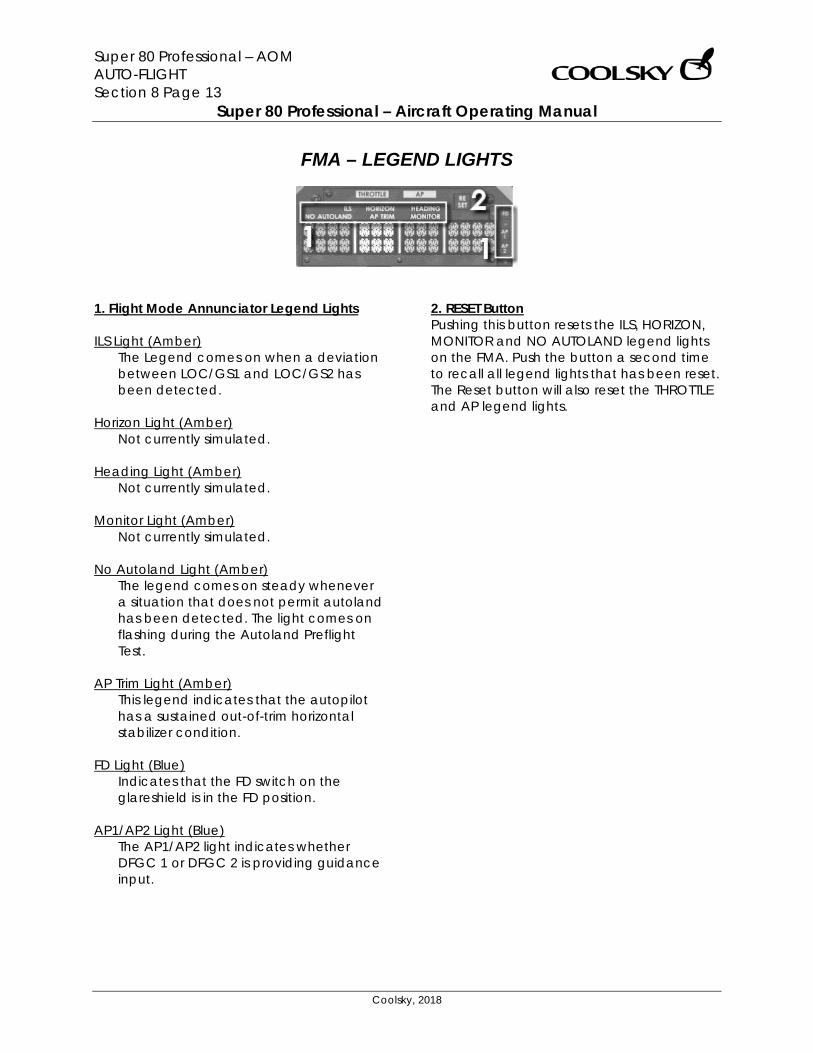
Super 80 Professional – AOM AUTO-FLIGHT Section 8 Page 13
Super 80 Professional – Aircraft Operating Manual
Coolsky, 2018
FMA – LEGEND LIGHTS
1. Flight Mode Annunciator Legend Lights ILS Light (Amber)
The Legend comes on when a deviation between LOC/GS1 and LOC/GS2 has been detected.
Horizon Light (Amber)
Not currently simulated. Heading Light (Amber)
Not currently simulated. Monitor Light (Amber)
Not currently simulated. No Autoland Light (Amber)
The legend comes on steady whenever a situation that does not permit autoland has been detected. The light comes on flashing during the Autoland Preflight Test.
AP Trim Light (Amber)
This legend indicates that the autopilot has a sustained out-of-trim horizontal stabilizer condition.
FD Light (Blue)
Indicates that the FD switch on the glareshield is in the FD position.
AP1/AP2 Light (Blue)
The AP1/AP2 light indicates whether DFGC 1 or DFGC 2 is providing guidance input.
2. RESET Button Pushing this button resets the ILS, HORIZON, MONITOR and NO AUTOLAND legend lights on the FMA. Push the button a second time to recall all legend lights that has been reset. The Reset button will also reset the THROTTLE and AP legend lights.
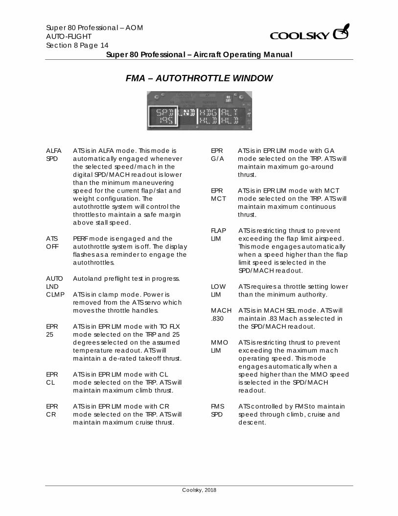
Super 80 Professional – AOM AUTO-FLIGHT Section 8 Page 14
Super 80 Professional – Aircraft Operating Manual
Coolsky, 2018
FMA – AUTOTHROTTLE WINDOW
ALFA SPD
ATS is in ALFA mode. This mode is automatically engaged whenever the selected speed/mach in the digital SPD/MACH readout is lower than the minimum maneuvering speed for the current flap/slat and weight configuration. The autothrottle system will control the throttles to maintain a safe margin above stall speed.
ATS OFF
PERF mode is engaged and the autothrottle system is off. The display flashes as a reminder to engage the autothrottles.
AUTO LND
Autoland preflight test in progress.
CLMP ATS is in clamp mode. Power is removed from the ATS servo which moves the throttle handles.
EPR 25
ATS is in EPR LIM mode with TO FLX mode selected on the TRP and 25 degrees selected on the assumed temperature readout. ATS will maintain a de-rated takeoff thrust.
EPR CL
ATS is in EPR LIM mode with CL mode selected on the TRP. ATS will maintain maximum climb thrust.
EPR CR
ATS is in EPR LIM mode with CR mode selected on the TRP. ATS will maintain maximum cruise thrust.
EPR G/A
ATS is in EPR LIM mode with GA mode selected on the TRP. ATS will maintain maximum go-around thrust.
EPR MCT
ATS is in EPR LIM mode with MCT mode selected on the TRP. ATS will maintain maximum continuous thrust.
FLAP LIM
ATS is restricting thrust to prevent exceeding the flap limit airspeed. This mode engages automatically when a speed higher than the flap limit speed is selected in the SPD/MACH readout.
LOW LIM
ATS requires a throttle setting lower than the minimum authority.
MACH .830
ATS is in MACH SEL mode. ATS will maintain .83 Mach as selected in the SPD/MACH readout.
MMO LIM
ATS is restricting thrust to prevent exceeding the maximum mach operating speed. This mode engages automatically when a speed higher than the MMO speed is selected in the SPD/MACH readout.
FMS SPD
ATS controlled by FMS to maintain speed through climb, cruise and descent.
Super 80 Professional – AOM AUTO-FLIGHT Section 8 Page 15
Super 80 Professional – Aircraft Operating Manual
Coolsky, 2018
FMS EPR
ATS controlled by FMS to maintain EPR through climb, cruise and descent.
FMS IDL
ATS controlled by FMS to maintain engines at idle thrust during descent.
PWR ATS automatic power up test is in progress.
RETD ATS is in retard mode. The throttles are automatically retarded during the flare maneuver of an autoland procedure.
SLAT LIM
ATS is restricting thrust to prevent exceeding the slat limit airspeed. This mode engages automatically when a speed higher than the slat limit speed is selected in the SPD/MACH readout. In this panel the FLAP LIM mode will be used to restrict thrust for both flaps and slats limit.
SPD 250
ATS is in SPD SEL mode. ATS will maintain the airspeed in the SPD/MACH readout.
SPD/ MACH ATL
ATS is in MACH SEL mode. ATS will maintain the mach number in the SPD/MACH readout.
VMO LIM
ATS is restricting thrust to prevent exceeding the maximum operating airspeed. This mode engages automatically when a speed higher than the VMO speed is selected in the SPD/MACH readout.
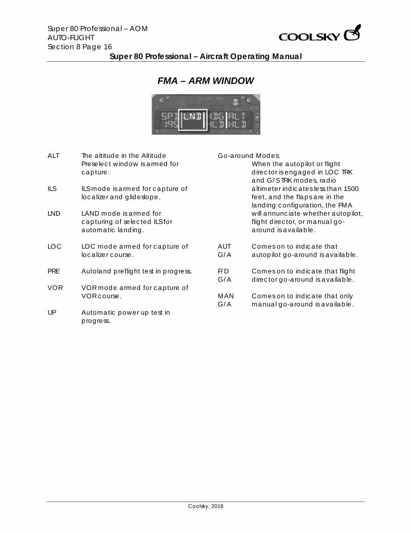
Super 80 Professional – AOM AUTO-FLIGHT Section 8 Page 16
Super 80 Professional – Aircraft Operating Manual
Coolsky, 2018
FMA – ARM WINDOW
ALT The altitude in the Altitude
Preselect window is armed for capture.
ILS ILS mode is armed for capture of localizer and glideslope.
LND LAND mode is armed for capturing of selected ILS for automatic landing.
LOC LOC mode armed for capture of localizer course.
PRE Autoland preflight test in progress.
VOR VOR mode armed for capture of VOR course.
UP Automatic power up test in progress.
Go-around Modes: When the autopilot or flight
director is engaged in LOC TRK and G/S TRK modes, radio altimeter indicates less than 1500 feet, and the flaps are in the landing configuration, the FMA will annunciate whether autopilot, flight director, or manual go-around is available.
AUT G/A
Comes on to indicate that autopilot go-around is available.
F/D G/A
Comes on to indicate that flight director go-around is available.
MAN G/A
Comes on to indicate that only manual go-around is available.

Super 80 Professional – AOM AUTO-FLIGHT Section 8 Page 17
Super 80 Professional – Aircraft Operating Manual
Coolsky, 2018
FMA – ROLL WINDOW
ALN When the autopilot is in LAND
mode, the Align sub-mode is engaged when the aircraft descends below 150 feet AGL. The align mode will transition the aircraft from a crab angle for crosswind correction to a forward slip (sideslip) to bring the aircraft in to alignment with the runway.
AUT LND
The autopilot is in LAND mode, both radios are tuned to the ILS frequency, radio altitude is less than 1500 feet, flaps are in the landing configuration, the localizer and glideslope are being tracked, and the AUTOLAND logic has been satisfied.
FLT Autoland preflight test in progress.
GO RND
Go-around mode has been engaged. If active, the autopilot and/or FD command bars will maintain the current heading of the aircraft.
HDG HLD
The autopilot is in heading hold mode. The DFGC will maintain the heading of the aircraft at the time the mode was engaged.
HDG SEL
The autopilot is in heading select mode. The DFGC is providing commands to maintain the heading in the HDG readout.
LOC CAP
The autopilot is engaged in either LOC, ILS or LAND mode, and capture of the localizer of the selected ILS has been initiated.
LOC TRK
The autopilot is engaged in either LOC, ILS or LAND mode, and the localizer of the selected ILS is being tracked.
NAV CAP
The autopilot is coupled to the FMS, and capture of the selected FMS course has been initiated.
NAV TRK
The autopilot is coupled to the FMS, and the selected FMS course is being tracked.
ROL OUT
At main gear spin-up, the autopilot will automatically switch to rollout mode. Go-around is disarmed. Runway center line will be maintained using the localizer.
TAK OFF
The FD take-off mode is engaged. The DFGC will command the FD command bars to maintain runway heading.
TST Automatic power up test in progress.
VOR CAP
The autopilot is engaged in VOR mode, and capture of the selected VOR radial has been initiated.
Super 80 Professional – AOM AUTO-FLIGHT Section 8 Page 18
Super 80 Professional – Aircraft Operating Manual
Coolsky, 2018
VOR CRS
The autopilot is engaged in VOR mode, and VOR station passage is occurring (cone of silence). The DFGC is maintaining the magnetic VOR course displayed in the CRS readout.
VOR TRK
The autopilot is engaged in VOR mode, and the selected VOR radial is being tracked.
WNG LVL
The Turbulence mode is engaged. The DFGC maintains wings level.
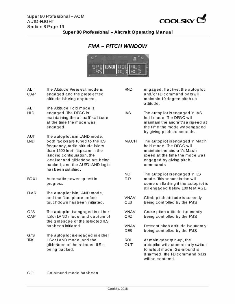
Super 80 Professional – AOM AUTO-FLIGHT Section 8 Page 19
Super 80 Professional – Aircraft Operating Manual
Coolsky, 2018
FMA – PITCH WINDOW
ALT CAP
The Altitude Preselect mode is engaged and the preselected altitude is being captured.
ALT HLD
The Altitude Hold mode is engaged. The DFGC is maintaining the aircraft’s altitude at the time the mode was engaged.
AUT LND
The autopilot is in LAND mode, both radios are tuned to the ILS frequency, radio altitude is less than 1500 feet, flaps are in the landing configuration, the localizer and glideslope are being tracked, and the AUTOLAND logic has been satisfied.
BOX1 Automatic power up test in progress.
FLAR The autopilot is in LAND mode, and the flare phase before touchdown has been initiated.
G/S CAP
The autopilot is engaged in either ILS or LAND mode, and capture of the glideslope of the selected ILS has been initiated.
G/S TRK
The autopilot is engaged in either ILS or LAND mode, and the glideslope of the selected ILS is being tracked.
GO Go-around mode has been
RND engaged. If active, the autopilot and/or FD command bars will maintain 10 degree pitch up attitude.
IAS The autopilot is engaged in IAS hold mode. The DFGC will maintain the aircraft’s airspeed at the time the mode was engaged by giving pitch commands.
MACH The autopilot is engaged in Mach hold mode. The DFGC will maintain the aircraft’s Mach speed at the time the mode was engaged by giving pitch commands.
NO FLR
The autopilot is engaged in ILS mode. This annunciation will come on flashing if the autopilot is still engaged below 100 feet AGL.
VNAV CLB
Climb pitch attitude is currently being controlled by the FMS.
VNAV CRZ
Cruise pitch attitude is currently being controlled by the FMS.
VNAV DES
Descent pitch attitude is currently being controlled by the FMS.
ROL OUT
At main gear spin-up, the autopilot will automatically switch to rollout mode. Go-around is disarmed. The FD command bars will be centered.
Super 80 Professional – AOM AUTO-FLIGHT Section 8 Page 20
Super 80 Professional – Aircraft Operating Manual
Coolsky, 2018
SPD LOW
This light comes on when a selected pitch mode has resulted in an airspeed which is lower than the ALFA reference speed by 10 percent.
TAK OFF
The FD take-off mode is engaged. The DFGC will command the FD command bars to maintain a 10 degree pitch up.
TEST Autoland preflight test in progress.
TURB The Turbulence mode is engaged. The DFGC maintains the aircraft’s pitch attitude at the time the
mode was engaged. Use the pitch control wheel to adjust the pitch attitude of the aircraft.
VERT SPD
The autopilot is engaged in basic Vertical Speed mode. The airplane vertical speed is being maintained by pitch attitude control.
Super 80 Professional – AOM APU Section 9 Page 0
Super 80 Professional – Aircraft Operating Manual
Coolsky, 2018
SECTION 9
APU
Super 80 Professional – AOM APU Section 9 Page 1
Super 80 Professional – Aircraft Operating Manual
Coolsky, 2018
TABLE OF CONTENTS
SECTION 9: APU 0
TABLE OF CONTENTS ................................................................................................................. 1 GENERAL .................................................................................................................................... 2 CONTROLS AND INDICATORS ................................................................................................. 3
Super 80 Professional – AOM APU Section 9 Page 2
Super 80 Professional – Aircraft Operating Manual
Coolsky, 2018
GENERAL General The Auxiliary Power Unit (APU) is a gas turbine engine installed to supply pneumatic requirements for cabin air conditioning and engine starting as well as electrical power for normal airplane systems operation while on the ground. The APU is operable in flight to supply an alternate source of electrical power. The APU installed aft of the rear pressure bulkhead in the unpressurized area of the lower fuselage. All APU controls and indicators are located on the overhead panel. Limitations The APU can be started on the ground or in-flight. Maximum operating altitude for the APU is FL350. Maximum starting altitude for the APU is FL240. APU bleed air is only available on the ground. Electrical system A 40 KVA power AC generator is mounted on the APU to provide electrical power to either or both electrical systems.
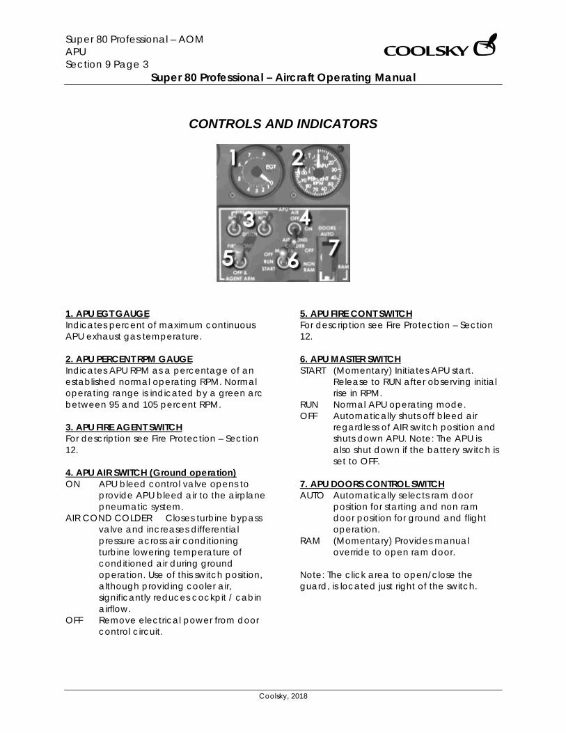
Super 80 Professional – AOM APU Section 9 Page 3
Super 80 Professional – Aircraft Operating Manual
Coolsky, 2018
CONTROLS AND INDICATORS
1. APU EGT GAUGE Indicates percent of maximum continuous APU exhaust gas temperature. 2. APU PERCENT RPM GAUGE Indicates APU RPM as a percentage of an established normal operating RPM. Normal operating range is indicated by a green arc between 95 and 105 percent RPM. 3. APU FIRE AGENT SWITCH For description see Fire Protection – Section 12. 4. APU AIR SWITCH (Ground operation) ON APU bleed control valve opens to
provide APU bleed air to the airplane pneumatic system.
AIR COND COLDER Closes turbine bypass valve and increases differential pressure across air conditioning turbine lowering temperature of conditioned air during ground operation. Use of this switch position, although providing cooler air, significantly reduces cockpit / cabin airflow.
OFF Remove electrical power from door control circuit.
5. APU FIRE CONT SWITCH For description see Fire Protection – Section 12. 6. APU MASTER SWITCH START (Momentary) Initiates APU start.
Release to RUN after observing initial rise in RPM.
RUN Normal APU operating mode. OFF Automatically shuts off bleed air
regardless of AIR switch position and shuts down APU. Note: The APU is also shut down if the battery switch is set to OFF.
7. APU DOORS CONTROL SWITCH AUTO Automatically selects ram door
position for starting and non ram door position for ground and flight operation.
RAM (Momentary) Provides manual override to open ram door.
Note: The click area to open/close the guard, is located just right of the switch.
Super 80 Professional – AOM COMMUNICATIONS Section 10 Page 0
Super 80 Professional – Aircraft Operating Manual
Coolsky, 2018
SECTION 10
COMMUNICATIONS
Super 80 Professional – AOM COMMUNICATIONS Section 10 Page 1
Super 80 Professional – Aircraft Operating Manual
Coolsky, 2018
TABLE OF CONTENTS
SECTION 10: COMMUNICATIONS 0
TABLE OF CONTENTS ................................................................................................................. 1 GENERAL .................................................................................................................................... 2 CONTROLS AND INDICATORS ................................................................................................. 3
Super 80 Professional – AOM COMMUNICATIONS Section 10 Page 2
Super 80 Professional – Aircraft Operating Manual
Coolsky, 2018
GENERAL VHF COMMUNICATIONS SYSTEMS The VHF communication systems are two separate identical systems designated VHF-l and VHF-2. The transmitting and receiving frequency selection is controlled from the VHF COMM control panels. Each panel has two frequency selectors and a transfer switch to select the transmitter frequency to be used. The VHF radios are located just aft of the throttle quadrant. MODE S TRANSPONDER A Mode S transponder is installed in the aircraft. In addition to ground replies for altitude identification, the Mode S transponder provides air-to-air surveillance and communication with other Mode S equipped airplanes for the purpose of collision avoidance. The transponder is located on the forward part of the pedestal. SELCAL Not currently simulated in the panel.
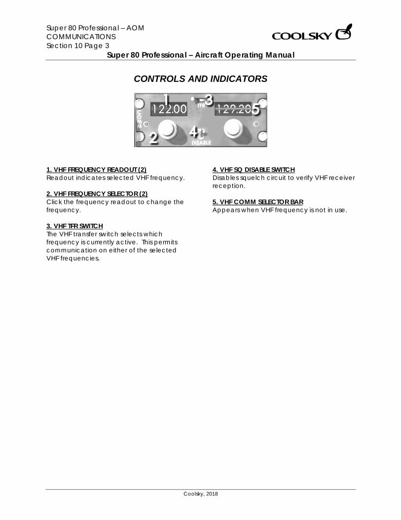
Super 80 Professional – AOM COMMUNICATIONS Section 10 Page 3
Super 80 Professional – Aircraft Operating Manual
Coolsky, 2018
CONTROLS AND INDICATORS
1. VHF FREQUENCY READOUT (2) Readout indicates selected VHF frequency. 2. VHF FREQUENCY SELECTOR (2) Click the frequency readout to change the frequency. 3. VHF TFR SWITCH The VHF transfer switch selects which frequency is currently active. This permits communication on either of the selected VHF frequencies.
4. VHF SQ DISABLE SWITCH Disables squelch circuit to verify VHF receiver reception. 5. VHF COMM SELECTOR BAR Appears when VHF frequency is not in use.
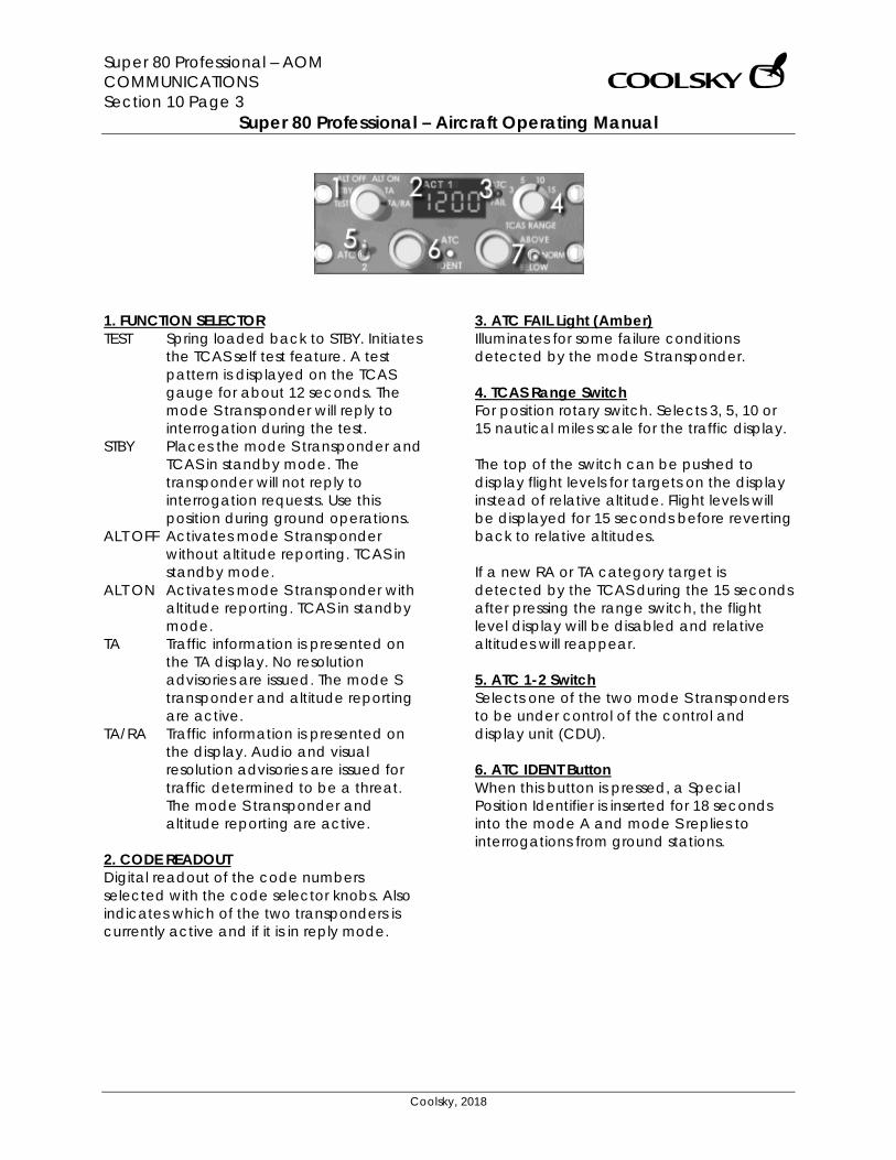
Super 80 Professional – AOM COMMUNICATIONS Section 10 Page 3
Super 80 Professional – Aircraft Operating Manual
Coolsky, 2018
1. FUNCTION SELECTOR TEST Spring loaded back to STBY. Initiates
the TCAS self test feature. A test pattern is displayed on the TCAS gauge for about 12 seconds. The mode S transponder will reply to interrogation during the test.
STBY Places the mode S transponder and TCAS in standby mode. The transponder will not reply to interrogation requests. Use this position during ground operations.
ALT OFF Activates mode S transponder without altitude reporting. TCAS in standby mode.
ALT ON Activates mode S transponder with altitude reporting. TCAS in standby mode.
TA Traffic information is presented on the TA display. No resolution advisories are issued. The mode S transponder and altitude reporting are active.
TA/RA Traffic information is presented on the display. Audio and visual resolution advisories are issued for traffic determined to be a threat. The mode S transponder and altitude reporting are active.
2. CODE READOUT Digital readout of the code numbers selected with the code selector knobs. Also indicates which of the two transponders is currently active and if it is in reply mode.
3. ATC FAIL Light (Amber) Illuminates for some failure conditions detected by the mode S transponder. 4. TCAS Range Switch For position rotary switch. Selects 3, 5, 10 or 15 nautical miles scale for the traffic display. The top of the switch can be pushed to display flight levels for targets on the display instead of relative altitude. Flight levels will be displayed for 15 seconds before reverting back to relative altitudes. If a new RA or TA category target is detected by the TCAS during the 15 seconds after pressing the range switch, the flight level display will be disabled and relative altitudes will reappear. 5. ATC 1-2 Switch Selects one of the two mode S transponders to be under control of the control and display unit (CDU). 6. ATC IDENT Button When this button is pressed, a Special Position Identifier is inserted for 18 seconds into the mode A and mode S replies to interrogations from ground stations.
Super 80 Professional – AOM COMMUNICATIONS Section 10 Page 4
Super 80 Professional – Aircraft Operating Manual
Coolsky, 2018
7. ABOVE/BELOW/NORM Switch Three position toggle switch. Selects relative altitude display limits for non-threat category targets (open white diamonds). ABOVE Selects display of non-threat
targets up to +8700 feet above own aircraft and down to -2700 feet below own aircraft.
NORM Selects display of non-threat targets up to +2700 feet above own aircraft and down to -2700 feet below own aircraft.
BELOW Selects display of non-threat
targets up to +2700 feet above own aircraft and down to -8700 feet below own aircraft.
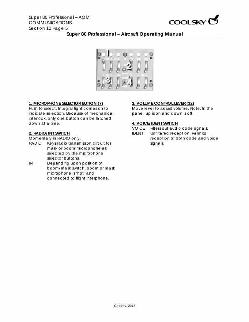
Super 80 Professional – AOM COMMUNICATIONS Section 10 Page 5
Super 80 Professional – Aircraft Operating Manual
Coolsky, 2018
1. MICROPHONE SELECTOR BUTTON (7) Push to select. Integral light comes on to indicate selection. Because of mechanical interlock, only one button can be latched down at a time. 2. RADIO/INT SWITCH Momentary in RADIO only. RADIO Keys radio transmission circuit for
mask or boom microphone as selected by the microphone selector buttons.
INT Depending upon position of boom/mask switch, boom or mask microphone is "hot" and connected to flight interphone.
3. VOLUME CONTROL LEVER (12) Move lever to adjust volume. Note: In the panel, up is on and down is off. 4. VOICE/IDENT SWITCH VOICE Filters out audio code signals. IDENT Unfiltered reception. Permits
reception of both code and voice signals.
Super 80 Professional – AOM ELECTRICAL Section 11 Page 0
Super 80 Professional – Aircraft Operating Manual
Coolsky, 2018
SECTION 11
ELECTRICAL

Super 80 Professional – AOM ELECTRICAL Section 11 Page 1
Super 80 Professional – Aircraft Operating Manual
Coolsky, 2018
TABLE OF CONTENTS
SECTION 11: ELECTRICAL 0
TABLE OF CONTENTS ................................................................................................................. 1 GENERAL .................................................................................................................................... 2 CONTROLS AND INDICATORS ................................................................................................. 4 WARNING AND CAUTION INDICATORS ................................................................................. 7
Super 80 Professional – AOM ELECTRICAL Section 11 Page 2
Super 80 Professional – Aircraft Operating Manual
Coolsky, 2018
GENERAL General The MD-80 electrical system is designed for simple and automatic operation. When a problem occurs, the system automatically takes the best course of action to maintain electrical power to the system. The airplane electrical power system consists of a 115 volt, 400 Hz AC power generating and distribution system. For control circuits, lighting and other load devices requiring DC power, 28 volt DC power is supplied by transformer-rectifiers (TR). Power for the DC system is supplied from two batteries when the main power distribution system is de-energized. A battery charger, powered from an AC bus, maintains the batteries in a charged state. The controls and indicators for the electrical system are located on the left side of the overhead panel. AC power generating system AC power is normally supplied by any of two or three AC generators, one on each engine and one on the auxiliary power unit (APU). Each generator is rated at 40 KVA maximum continuous output and is capable of supplying sufficient power for operation of essential electric systems in the event of loss of the other two generators. For ground operations, an external power source may be connected to the airplane. The external power receptacle is located on the lower fuselage, left side. The APU generator is mounted directly on the APU, and driven at a constant speed by the APU governing system.
Each engine-driven generator is driven through a constant-speed drive (CSD), which converts the variable speed output of the engine to a constant speed. AC power distribution system The electrical system is comprised of independent left and right systems which are normally powered by the respective engine driven generator. APU power and external power may be selected to power either or both generator buses. The Ground Service Bus provides power to those circuits necessary for ground servicing operations. An automatic priority system is installed to determine which power source is used. Power is automatically applied from the highest available priority source. Electrical system priority:
1. Engine generator 2. APU generator 3. External power 4. AC crosstie relay
Example: If the APU is supplying power to the bus, and an engine driven generator is placed on the bus, the APU generator will automatically be taken off the bus. The shutdown of a generator will automatically transfer the load from that generator to the remaining operating generator, through the AC crosstie relay.

Super 80 Professional – AOM ELECTRICAL Section 11 Page 3
Super 80 Professional – Aircraft Operating Manual
Coolsky, 2018
DC power distribution system The function of the DC power distribution system is similar to the AC system in that the right and left system function separately. The DC system has a manual crosstie in the event of a failure of either side. In addition to the left and right systems, DC power is supplied from the battery. Batteries Two 14 volt batteries are connected in series to supply 28 volt DC power. The battery is automatically being charged when electrical power is on the aircraft and the battery switch is ON. When operating on emergency power, the batteries should last for 30 minutes. Battery charger The battery charger is operative when the aircraft power is on, and the battery switch is in the ON position. When the battery is fully charged, the battery charger will be in a pulsating mode. If the battery is in a low state of charge, the ammeter will indicate a continuous current of approximately 65 amperes, and then switch into a pulsating mode as the battery becomes fully charged.
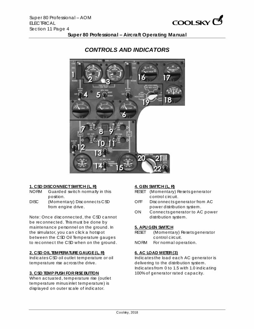
Super 80 Professional – AOM ELECTRICAL Section 11 Page 4
Super 80 Professional – Aircraft Operating Manual
Coolsky, 2018
CONTROLS AND INDICATORS
1. CSD DISCONNECT SWITCH (L, R) NORM Guarded switch normally in this
position. DISC (Momentary) Disconnects CSD
from engine drive. Note: Once disconnected, the CSD cannot be reconnected. This must be done by maintenance personnel on the ground. In the simulator, you can click a hotspot between the CSD Oil Temperature gauges to reconnect the CSD when on the ground. 2. CSD OIL TEMPERATURE GAUGE (L, R) Indicates CSD oil outlet temperature or oil temperature rise across the drive. 3. CSD TEMP PUSH FOR RISE BUTTON When actuated, temperature rise (outlet temperature minus inlet temperature) is displayed on outer scale of indicator.
4. GEN SWITCH (L, R) RESET (Momentary) Resets generator
control circuit. OFF Disconnects generator from AC
power distribution system. ON Connects generator to AC power
distribution system. 5. APU GEN SWITCH RESET (Momentary) Resets generator
control circuit. NORM For normal operation. 6. AC LOAD METER (3) Indicates the load each AC generator is delivering to the distribution system. Indicates from 0 to 1.5 with 1.0 indicating 100% of generator rated capacity.
Super 80 Professional – AOM ELECTRICAL Section 11 Page 5
Super 80 Professional – Aircraft Operating Manual
Coolsky, 2018
7. POWER IN USE LIGHT (4) Indicates selected power source is connected to respective bus. 8. APU PWR AVAIL LIGHT Indicates APU power is available. 9. APU BUS SWITCH (L, R) OFF Removes APU power from respective
buses. ON Selects APU power to respective
buses. 10. EXT PWR AVAIL LIGHT Indicates external power is available. 11. EXT PWR BUS SWITCH (L, R) OFF Removes external power from
selected bus. ON Selects external power to respective
bus. 12. GALLEY SWITCH OFF De-energizes galley power relays
removing power from all galleys. ON Energizes galley power relays which
supply power to all galleys. 13. AC BUS X TIE SWITCH OPEN Opens AG crosstie relay, isolating left
and right AG distribution systems. Prevents automatic closing of relay with loss of left or right AG bus power.
AUTO Normally operated in this position. With loss of left or right AG bus power, relay closes automatically, connecting the two buses together.
14. DC BUS X TIE SWITCH CLOSE Connects left and right DC buses,
allowing any combination of T/R’s to power both DC buses.
OPEN Normal position. Isolates left and right DC distribution systems.
15. DC LOAD METER (L, R) Indicates load the respective T/R is delivering to the distribution system. Reading of 1 indicates 100% of T/R rated capacity. 16. AC VOLTS METER Indicates voltage output of generators or external power. 17. FREQUENCY METER Indicates frequency control of generator or external power in cycles per second. 18. DC VOLTS/AMPS METER Indicates charge or discharge current of battery, battery voltage, or DC bus voltage. 19. INDICATOR SELECTOR SWITCH When moved to either L or R positions, AC voltage and frequency for selected sources are read on respective meters. All other positions select only a single source as indicated on switch placard. 20. EMER PWR SWITCH OFF Removes battery as source of
emergency power. ON Connects battery as source of
emergency AC and DC power. 21. EMER PWR IN USE LIGHT Indicates emergency power is on. 22. BATT SWITCH OFF Removes battery from battery bus,
battery charger and DC transfer bus. ON Connects battery to battery bus.
Selects battery to battery charger, and DC transfer bus.
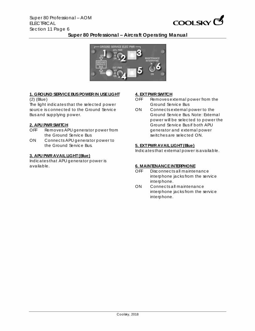
Super 80 Professional – AOM ELECTRICAL Section 11 Page 6
Super 80 Professional – Aircraft Operating Manual
Coolsky, 2018
1. GROUND SERVICE BUS POWER IN USE LIGHT (2) (Blue) The light indicates that the selected power source is connected to the Ground Service Bus and supplying power. 2. APU PWR SWITCH OFF Removes APU generator power from
the Ground Service Bus ON Connects APU generator power to
the Ground Service Bus. 3. APU PWR AVAIL LIGHT (Blue) Indicates that APU generator power is available.
4. EXT PWR SWITCH OFF Removes external power from the
Ground Service Bus ON Connects external power to the
Ground Service Bus. Note: External power will be selected to power the Ground Service Bus if both APU generator and external power switches are selected ON.
5. EXT PWR AVAIL LIGHT (Blue) Indicates that external power is available. 6. MAINTENANCE INTERPHONE OFF Disconnects all maintenance
interphone jacks from the service interphone.
ON Connects all maintenance interphone jacks from the service interphone.
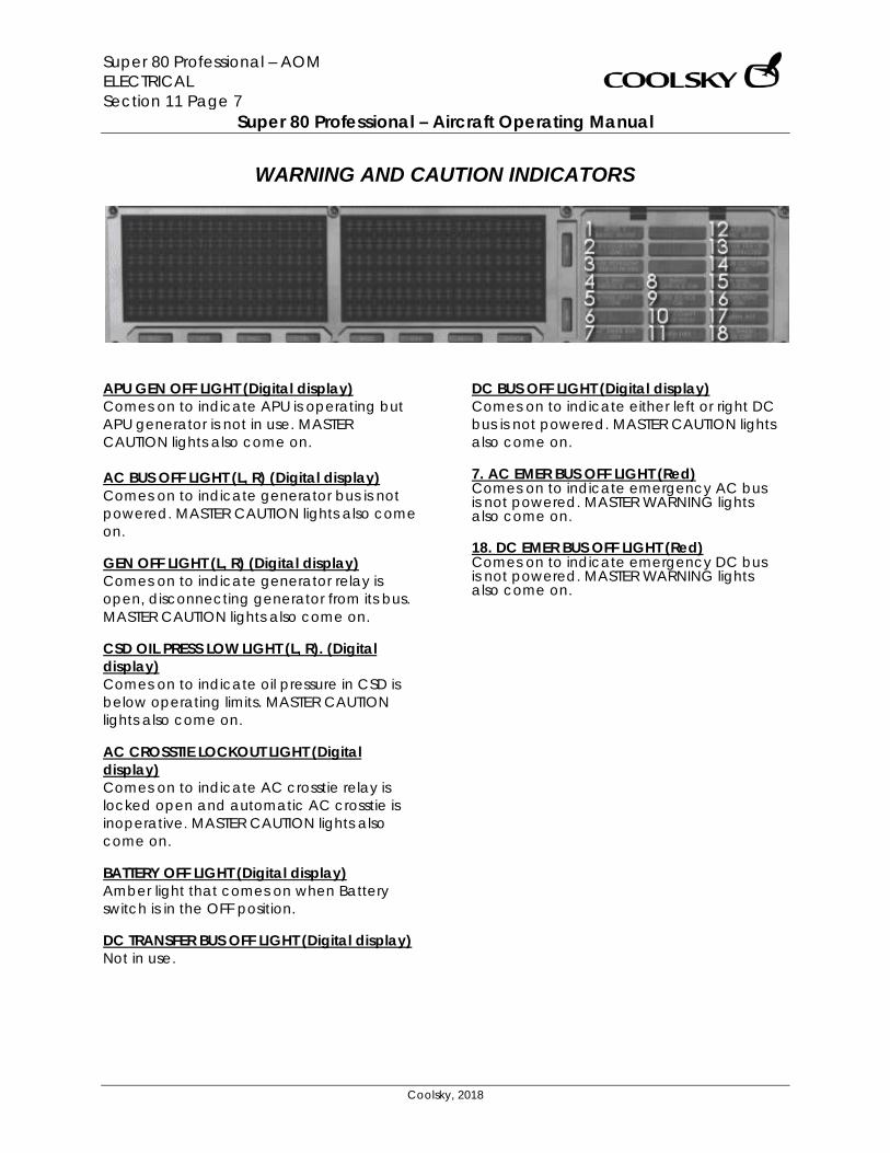
Super 80 Professional – AOM ELECTRICAL Section 11 Page 7
Super 80 Professional – Aircraft Operating Manual
Coolsky, 2018
WARNING AND CAUTION INDICATORS
APU GEN OFF LIGHT (Digital display) Comes on to indicate APU is operating but APU generator is not in use. MASTER CAUTION lights also come on. AC BUS OFF LIGHT (L, R) (Digital display) Comes on to indicate generator bus is not powered. MASTER CAUTION lights also come on. GEN OFF LIGHT (L, R) (Digital display) Comes on to indicate generator relay is open, disconnecting generator from its bus. MASTER CAUTION lights also come on. CSD OIL PRESS LOW LIGHT (L, R). (Digital display) Comes on to indicate oil pressure in CSD is below operating limits. MASTER CAUTION lights also come on. AC CROSSTIE LOCKOUT LIGHT (Digital display) Comes on to indicate AC crosstie relay is locked open and automatic AC crosstie is inoperative. MASTER CAUTION lights also come on. BATTERY OFF LIGHT (Digital display) Amber light that comes on when Battery switch is in the OFF position. DC TRANSFER BUS OFF LIGHT (Digital display) Not in use.
DC BUS OFF LIGHT (Digital display) Comes on to indicate either left or right DC bus is not powered. MASTER CAUTION lights also come on. 7. AC EMER BUS OFF LIGHT (Red) Comes on to indicate emergency AC bus is not powered. MASTER WARNING lights also come on. 18. DC EMER BUS OFF LIGHT (Red) Comes on to indicate emergency DC bus is not powered. MASTER WARNING lights also come on.
Super 80 Professional – AOM FIRE PROTECTION Section 12 Page 0
Super 80 Professional – Aircraft Operating Manual
Coolsky, 2018
SECTION 12
FIRE PROTECTION
Super 80 Professional – AOM FIRE PROTECTION Section 12 Page 1
Super 80 Professional – Aircraft Operating Manual
Coolsky, 2018
TABLE OF CONTENTS
SECTION 12: FIRE PROTECTION 0
TABLE OF CONTENTS ................................................................................................................. 1 GENERAL .................................................................................................................................... 2 CONTROLS AND INDICATORS ................................................................................................. 3
Super 80 Professional – AOM FIRE PROTECTION Section 12 Page 2
Super 80 Professional – Aircraft Operating Manual
Coolsky, 2018
GENERAL General A fire detection system is provided for each engine and the APU. Each detection system consists of two detector loops mounted parallel to each other. With the loop switch set to BOTH, only one loop needs to detect a fire or overheat condition to activate the fire warning system. Fire Warning System The fire warning for an engine fire consists of the following lights and warning sounds:
• A red ENG FIRE light located in the fire handle on the upper main instrument panel.
• The MASTER CAUTION light on the glareshield.
• Aural warnings (fire bell and vocal) from the central aural warning system.
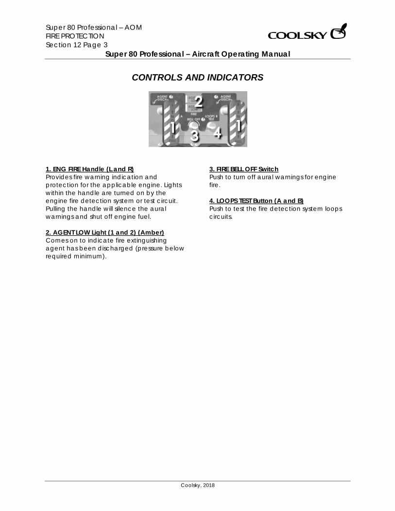
Super 80 Professional – AOM FIRE PROTECTION Section 12 Page 3
Super 80 Professional – Aircraft Operating Manual
Coolsky, 2018
CONTROLS AND INDICATORS
1. ENG FIRE Handle (L and R) Provides fire warning indication and protection for the applicable engine. Lights within the handle are turned on by the engine fire detection system or test circuit. Pulling the handle will silence the aural warnings and shut off engine fuel. 2. AGENT LOW Light (1 and 2) (Amber) Comes on to indicate fire extinguishing agent has been discharged (pressure below required minimum).
3. FIRE BELL OFF Switch Push to turn off aural warnings for engine fire. 4. LOOPS TEST Button (A and B) Push to test the fire detection system loops circuits.
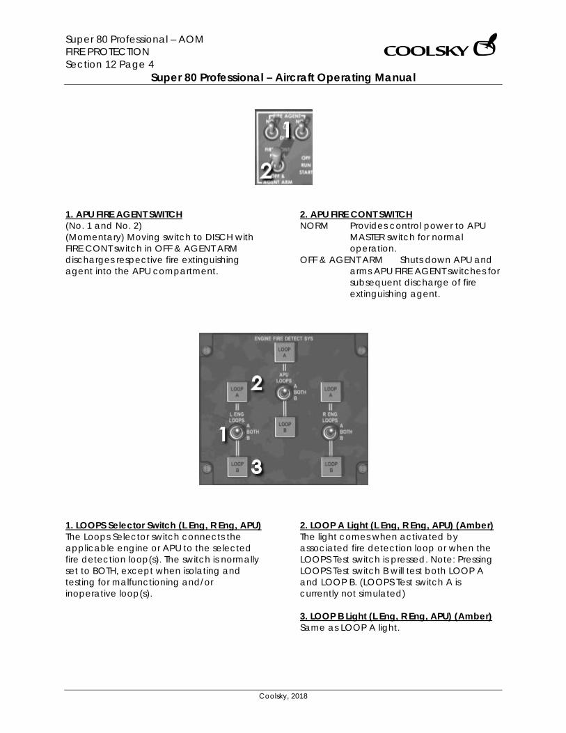
Super 80 Professional – AOM FIRE PROTECTION Section 12 Page 4
Super 80 Professional – Aircraft Operating Manual
Coolsky, 2018
1. APU FIRE AGENT SWITCH (No. 1 and No. 2) (Momentary) Moving switch to DISCH with FIRE CONT switch in OFF & AGENT ARM discharges respective fire extinguishing agent into the APU compartment.
2. APU FIRE CONT SWITCH NORM Provides control power to APU
MASTER switch for normal operation.
OFF & AGENT ARM Shuts down APU and arms APU FIRE AGENT switches for subsequent discharge of fire extinguishing agent.
1. LOOPS Selector Switch (L Eng, R Eng, APU) The Loops Selector switch connects the applicable engine or APU to the selected fire detection loop(s). The switch is normally set to BOTH, except when isolating and testing for malfunctioning and/or inoperative loop(s).
2. LOOP A Light (L Eng, R Eng, APU) (Amber) The light comes when activated by associated fire detection loop or when the LOOPS Test switch is pressed. Note: Pressing LOOPS Test switch B will test both LOOP A and LOOP B. (LOOPS Test switch A is currently not simulated) 3. LOOP B Light (L Eng, R Eng, APU) (Amber) Same as LOOP A light.
Super 80 Professional – AOM FLIGHT CONTROLS Section 13 Page 0
Super 80 Professional – Aircraft Operating Manual
Coolsky, 2018
SECTION 13
FLIGHT CONTROLS

Super 80 Professional – AOM FLIGHT CONTROLS Section 13 Page 1
Super 80 Professional – Aircraft Operating Manual
Coolsky, 2018
TABLE OF CONTENTS
SECTION 13: FLIGHT CONTROLS 0
TABLE OF CONTENTS ................................................................................................................. 1 GENERAL .................................................................................................................................... 2 MAJOR COMPONENT LOCATION .......................................................................................... 7 LONGITUDINAL CONTROL AND TRIM ..................................................................................... 8 RUDDER CONTROL AND TRIM ............................................................................................... 11 SPEEDBRAKE/SPOILER ............................................................................................................. 12 FLAP/SLAT SYSTEM ................................................................................................................... 13 MACH TRIM AND STALL WARNING ....................................................................................... 14 WARNING INDICATORS .......................................................................................................... 15
Super 80 Professional – AOM FLIGHT CONTROLS Section 13 Page 2
Super 80 Professional – Aircraft Operating Manual
Coolsky, 2018
GENERAL
The primary flight controls of the airplane consist of aileron, rudder and elevator control systems. Secondary flight controls consist of leading-edge slats, flight and ground spoilers, inboard and outboard flaps, and horizontal stabilizer. PRIMARY FLIGHT CONTROLS Lateral Control System The ailerons provide the primary roll control and are augmented by the flight spoilers when increased roll control is required. The control column in the cockpit is cable connected to an aileron control tab which controls aileron movement. In flight, the deflecting control tab will cause the aileron to aerodynamically position. Aileron trim is provided by a separate tab on each aileron. The trim tab is cable controlled by the Aileron Trim knob on the aft pedestal. Longitudinal Control System Each elevator operates independently. Each elevator is controlled by a single control tab located inboard on the elevator. The control tabs are cable connected to the control column. A gear tab is installed outboard of the control tab on the elevator. The gear tab is linked to move in the opposite direction of the elevator. Thus, the gear tab always assists the operation of the control tab.
An anti-float tab, geared to horizontal stabilizer movement, is installed outboard of the gear tab. The purpose of the anti-float tab is to fly the elevator up when the horizontal stabilizer is trimmed nose up. Without this tab, the elevators tend to float at extreme nose-up trim settings. Stabilizer trim is accomplished by actuation of the LONG TRIM handle on the pedestal. Engine strakes are added to the engine nacelles to enhance longitudinal control for stall recovery. The elevators normally operate aerodynamically. However, for extreme high angle of attack flight conditions, a 3000 PSI hydraulic power augmentation system is installed for additional nose down capability. This feature is called Elevator Augmentation. The main purpose for the Elevator Augmentation system is to allow the airplane to recover from a deep stall when natural airflow across the tail is insufficient to “fly” the elevators. A Mach Trim Compensator is installed on the First Officer’s control column. The Mach Trim Compensator provides force to move the columns slightly aft when the airspeed is above M.80. This action offsets the effects of Mach Tuck that occurs at high speeds. When the airplane is parked, it is possible for the elevators to split due to tail winds. When this occurs, the flight crew may notice the control columns feel locked in position. The condition is removed as soon as the airplane is taxied and the natural airflow of the tail “flies” the elevator toward the neutral position.

Super 80 Professional – AOM FLIGHT CONTROLS Section 13 Page 3
Super 80 Professional – Aircraft Operating Manual
Coolsky, 2018
Rudder System The rudder normally operates in the powered mode and is actuated by hydraulic pressure. In the event of a system failure or by pilot selection, the rudder may operate in manual mode actuated by a control tab. Powered Rudder Operation During powered rudder operation, the control tab is locked and the rudder is actuated by hydraulic pressure from the right system based on rudder pedal input. Hydraulic power to the rudder may be shut off by placing the rudder power control handle in the manual position. When hydraulic pressure drops below 950 PSI, the rudder automatically reverts to manual operation. Trim is accomplished by turning the trim knob on the pedestal. Manual Rudder Operation During manual rudder operation, rudder pedal movement operates a control tab on the rudder. Trim is accomplished by turning the trim knob on the pedestal. Rudder Throw Limiter A Rudder Throw Limiter is installed to protect the empennage from overload in case of inadvertent application of excessive rudder control. The limiter operates by ram air pressure from the pitot tube on the leading edge of the vertical stabilizer. The higher the speed, the more restriction on rudder movement. A Rudder Unrestricted light on the overhead annunciator panel comes on whenever full rudder throw is available. Nose strakes are added to the forward part of the fuselage to enhance directional control during high angle of attack flight.
The rudder pitot tube is electrically heated whenever probe heat is on. Yaw Damper A yaw damper is installed to provide damping of any lateral directional oscillation. SECONDARY FLIGHT CONTROLS Spoiler System Each wing has inboard and outboard flight spoilers that are operational during all phases of flight. Flight Spoilers There are two Flight Spoiler panel on each wing. These panels have a threefold purpose:
• They are used as roll augmentation devices.
• They are used as speed brakes when the aircraft is in-flight.
• They are used on the ground to act as Ground Spoilers.
Super 80 Professional – AOM FLIGHT CONTROLS Section 13 Page 4
Super 80 Professional – Aircraft Operating Manual
Coolsky, 2018
Speed Brakes In flight, manually moving the spoiler lever aft will extend the four flight spoilers to serve as speed brakes. When used as speed brakes, the spoiler panels will extend symmetrically up to a maximum of 35 degrees. In flight, if the speedbrakes are extended with the flaps extended 6 degrees or more, the Spoiler/Flap Extended light on the overhead annunciator panel and the Master Caution light will come on, and a warning horn will sound accompanied by the word “Speedbrake”. On the ground, if either throttle is advanced with the spoiler lever not fully forward, the take-off warning horn will sound accompanied by the word “Spoilers”. Ground Spoilers There is one inboard Ground Spoiler panel on each wing. These panels are locked down in-flight and electrically unlocked on the ground. The Ground Spoilers will only operate during landing and rejected take-offs. Spoiler Operation – Take-Off The spoilers are armed for take-off by squeezing the spoiler handle and raising it to the armed position. Arming the spoilers for take-off without positioning the AUTO BRAKE selector to TO causes the take-off warning horn to sound (when the throttles are advanced) accompanied by the words “Auto brake”. Likewise, positioning the AUTO BRAKE switch to TO without arming the spoilers will cause the take-off warning horn to sound accompanied by the words “Auto Spoiler”. When the throttles are retarded to idle and reverse thrust selected during a rejected
take-off, the spoilers will automatically deploy and initiate automatic braking. All spoiler panels will be extended to 60 degrees. Auto spoilers and auto brakes are applied until pilot takeover, by stowing the spoilers, or the airplane comes to a full stop. Spoiler Operation – Landing At main gear wheel spin up or nose strut compression, the spoilers are automatically deployed and extended to 60 degrees. In the event of a go-around, the spoilers will automatically retract upon advancing the left throttle lever. Flaps System There are two flap segments on the trailing edge of each wing. The segments are interconnected to form one flap on each wing. Flaps may be positioned in any of six permanent detents in a 0 to 40 degree range by movement of the flap/slat handle. Available flaps detents in the Super 80 Pro are: 0, 11, 15, 28 and 40 degrees.
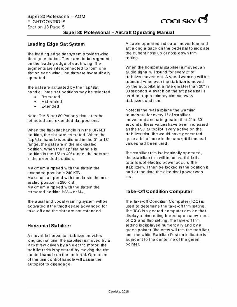
Super 80 Professional – AOM FLIGHT CONTROLS Section 13 Page 5
Super 80 Professional – Aircraft Operating Manual
Coolsky, 2018
Leading Edge Slat System The leading edge slat system provides wing lift augmentation. There are six slat segments on the leading edge of each wing. The segments are interconnected to form one slat on each wing. The slats are hydraulically operated. The slats are actuated by the flap/slat handle. Three slat positions may be selected:
• Retracted • Mid-sealed • Extended
Note: The Super 80 Pro only simulates the retracted and extended slat positions.
When the flap/slat handle is in the UP/RET position, the slats are retracted. When the flap/slat handle is positioned in the 0° to 13° range, the slats are in the mid-sealed position. When the flap/slat handle is position in the 15° to 40° range, the slats are in the extended position. Maximum airspeed with the slats in the extended position is 240 KTS. Maximum airspeed with the slats in the mid-sealed position is 280 KTS. Maximum airspeed with the slats in the retracted position is Vmo or Mmo. The aural and vocal warning system will be activated if the throttles are advanced for take-off and the slats are not extended. Horizontal Stabilizer A movable horizontal stabilizer provides longitudinal trim. The stabilizer is moved by a jackscrew driven by an electric motor. The stabilizer trim is operated by moving the trim control handle on the pedestal. Operation of the trim control handle will cause the autopilot to disengage.
A cable operated indicator moves fore and aft along a track on the pedestal to indicate the current nose up or nose down trim setting. When the horizontal stabilizer is moved, an audio signal will sound for every 2° of stabilizer movement. A vocal warning will be sounded whenever the stabilizer is moved by the autopilot at a rate greater than 20° in 30 seconds. A switch on the aft pedestal is used to stop a primary-trim runaway stabilizer condition. Note: In the real airplane the warning sounds are for every 1° of stabilizer movement and rate greater that 2° in 30 seconds. These values have been increased as the P3D autopilot is very active on the stabilizer trim. This would have generated quite a bit of noise in the cockpit if the real values had been used. The stabilizer trim is electrically operated, thus stabilizer trim will be unavailable if a total loss of electric power occurs. The stabilizer will then be locked in the position it had at the time the electrical power was lost. Take-Off Condition Computer The Take-off Condition Computer (TCC) is used to determine the take-off trim setting. The TCC is a geared computer device that display a trim setting based upon crew input of CG and flap setting. The take-off trim setting is displayed numerically and by a green pointer. The crew will trim the stabilizer until the white Stabilizer Position Indicator is adjacent to the centerline of the green pointer.
Super 80 Professional – AOM FLIGHT CONTROLS Section 13 Page 6
Super 80 Professional – Aircraft Operating Manual
Coolsky, 2018
Take-off Warning A take-off audible warning signal and voice warning will sound if the throttles are advanced for take-off together with at least one of the following conditions:
• the stabilizer trim is not set according to the computed take-off trim setting
• the flap/slat handle is not set in accordance with the setting on the Take-off Condition Computer
• the slats are not extended • the spoiler lever is not fully forward • the parking brakes are on.
Stall Protection System Prior to the onset of a stall, the stall protection system will be activated. The airplane is equipped with two stall detection systems, each receiving input from an angle-of-attack vane, the horizontal stabilizer and the slat/flap position transmitters. When approaching a stalled condition the following will be activated:
• SPD LOW in the Pitch FMA window • Stick Shaker will be activated. • At stall the claxon aural warning and
vocal “Stall” will sound. • Stall warning light will come one. • Stick Pusher will be activated.
Autoslats When the flap/slat handle is set to the 0 – 13 degrees range and the aircraft speed is less than 240kts, the slats will automatically be extended from the mid-sealed to the extended position if a stalled condition is detected. The slats DISAGREE and AUTO lights will come on indicating the autoslat system is operating. The slats will automatically be retracted to the mid-sealed position when the stalled condition ends. The slat system will automatically do a self-test whenever take-off flaps is selected (0 – 13) on the ground. The slats DISAGREE and AUTO lights will come on during the test. Post Stall Pusher System Whenever a stall is detected, the control column will be abruptly moved forward, the STICK PUSHER PUSH TO INHIBIT glareshield light will come on, and the autopilot, if engaged, will be disconnected. The Post Stall Pusher System will keep forward pressure on the control column until the airplane has come out of the stalled condition or the STICK PUSHER PUSH TO INHIBIT glareshield light is pushed in.
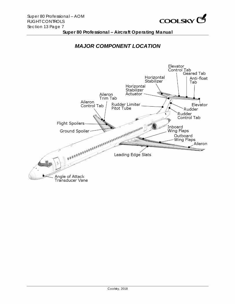
Super 80 Professional – AOM FLIGHT CONTROLS Section 13 Page 7
Super 80 Professional – Aircraft Operating Manual
Coolsky, 2018
MAJOR COMPONENT LOCATION
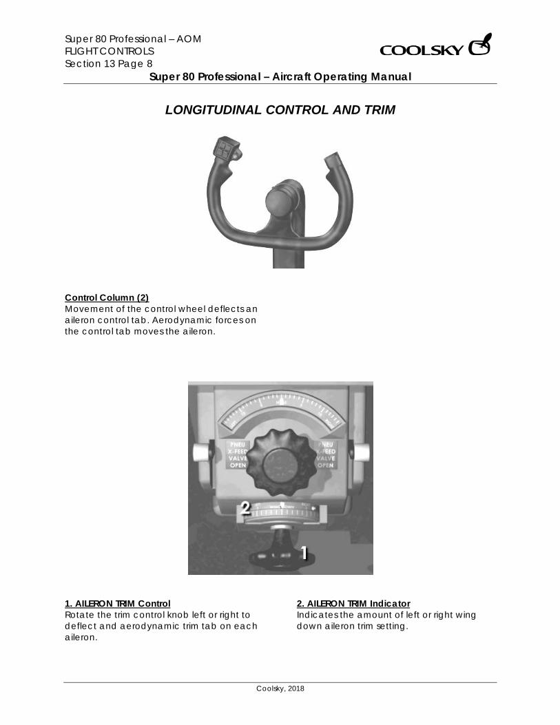
Super 80 Professional – AOM FLIGHT CONTROLS Section 13 Page 8
Super 80 Professional – Aircraft Operating Manual
Coolsky, 2018
LONGITUDINAL CONTROL AND TRIM
Control Column (2) Movement of the control wheel deflects an aileron control tab. Aerodynamic forces on the control tab moves the aileron.
1. AILERON TRIM Control Rotate the trim control knob left or right to deflect and aerodynamic trim tab on each aileron.
2. AILERON TRIM Indicator Indicates the amount of left or right wing down aileron trim setting.
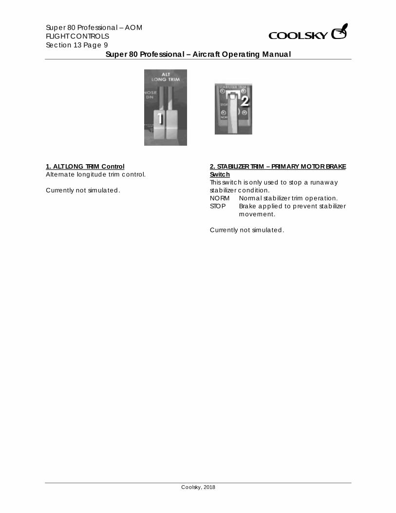
Super 80 Professional – AOM FLIGHT CONTROLS Section 13 Page 9
Super 80 Professional – Aircraft Operating Manual
Coolsky, 2018
1. ALT LONG TRIM Control Alternate longitude trim control. Currently not simulated.
2. STABILIZER TRIM – PRIMARY MOTOR BRAKE Switch This switch is only used to stop a runaway stabilizer condition. NORM Normal stabilizer trim operation. STOP Brake applied to prevent stabilizer
movement. Currently not simulated.
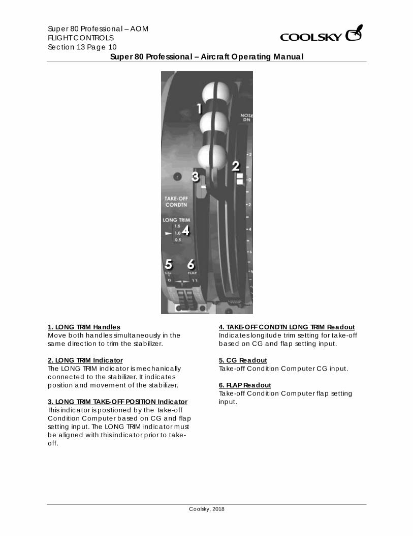
Super 80 Professional – AOM FLIGHT CONTROLS Section 13 Page 10
Super 80 Professional – Aircraft Operating Manual
Coolsky, 2018
1. LONG TRIM Handles Move both handles simultaneously in the same direction to trim the stabilizer. 2. LONG TRIM Indicator The LONG TRIM indicator is mechanically connected to the stabilizer. It indicates position and movement of the stabilizer. 3. LONG TRIM TAKE-OFF POSITION Indicator This indicator is positioned by the Take-off Condition Computer based on CG and flap setting input. The LONG TRIM indicator must be aligned with this indicator prior to take-off.
4. TAKE-OFF CONDTN LONG TRIM Readout Indicates longitude trim setting for take-off based on CG and flap setting input. 5. CG Readout Take-off Condition Computer CG input. 6. FLAP Readout Take-off Condition Computer flap setting input.
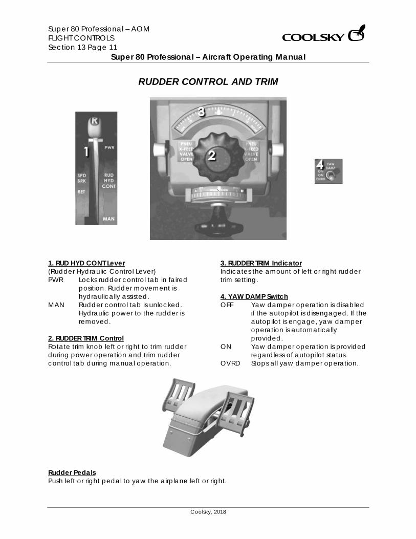
Super 80 Professional – AOM FLIGHT CONTROLS Section 13 Page 11
Super 80 Professional – Aircraft Operating Manual
Coolsky, 2018
RUDDER CONTROL AND TRIM
1. RUD HYD CONT Lever (Rudder Hydraulic Control Lever) PWR Locks rudder control tab in faired
position. Rudder movement is hydraulically assisted.
MAN Rudder control tab is unlocked. Hydraulic power to the rudder is removed.
2. RUDDER TRIM Control Rotate trim knob left or right to trim rudder during power operation and trim rudder control tab during manual operation.
3. RUDDER TRIM Indicator Indicates the amount of left or right rudder trim setting. 4. YAW DAMP Switch OFF Yaw damper operation is disabled
if the autopilot is disengaged. If the autopilot is engage, yaw damper operation is automatically provided.
ON Yaw damper operation is provided regardless of autopilot status.
OVRD Stops all yaw damper operation.
Rudder Pedals Push left or right pedal to yaw the airplane left or right.
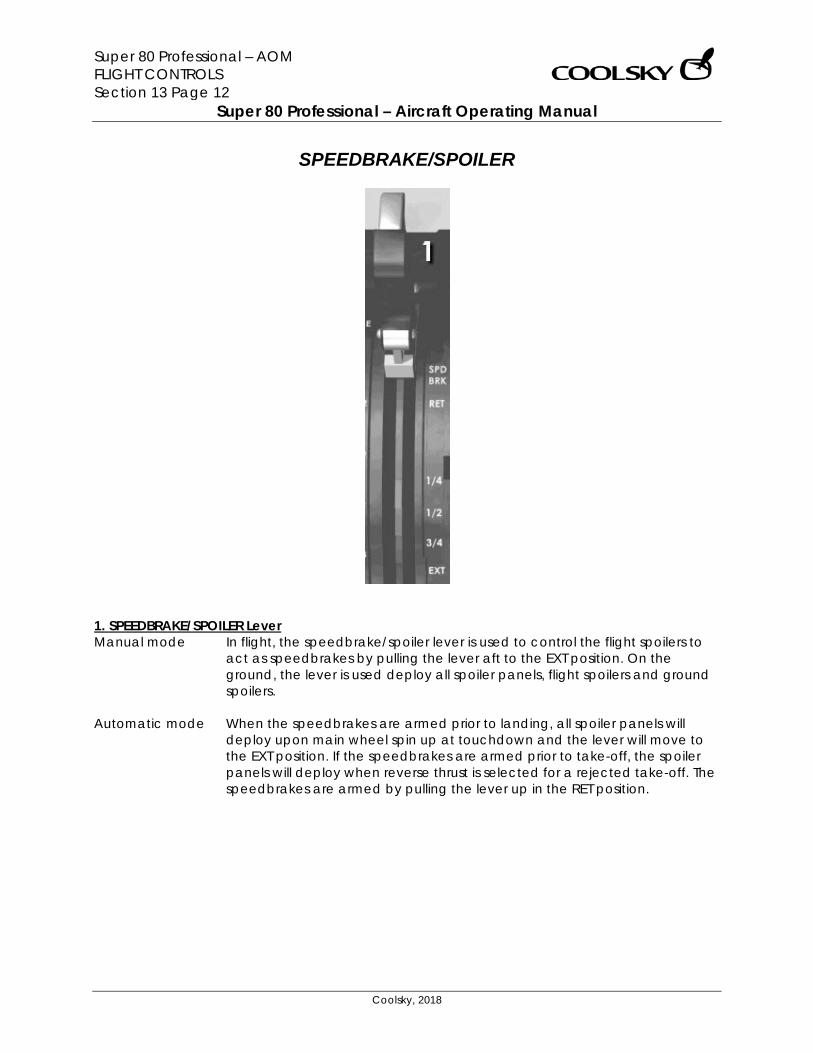
Super 80 Professional – AOM FLIGHT CONTROLS Section 13 Page 12
Super 80 Professional – Aircraft Operating Manual
Coolsky, 2018
SPEEDBRAKE/SPOILER
1. SPEEDBRAKE/SPOILER Lever Manual mode In flight, the speedbrake/spoiler lever is used to control the flight spoilers to
act as speedbrakes by pulling the lever aft to the EXT position. On the ground, the lever is used deploy all spoiler panels, flight spoilers and ground spoilers.
Automatic mode When the speedbrakes are armed prior to landing, all spoiler panels will
deploy upon main wheel spin up at touchdown and the lever will move to the EXT position. If the speedbrakes are armed prior to take-off, the spoiler panels will deploy when reverse thrust is selected for a rejected take-off. The speedbrakes are armed by pulling the lever up in the RET position.
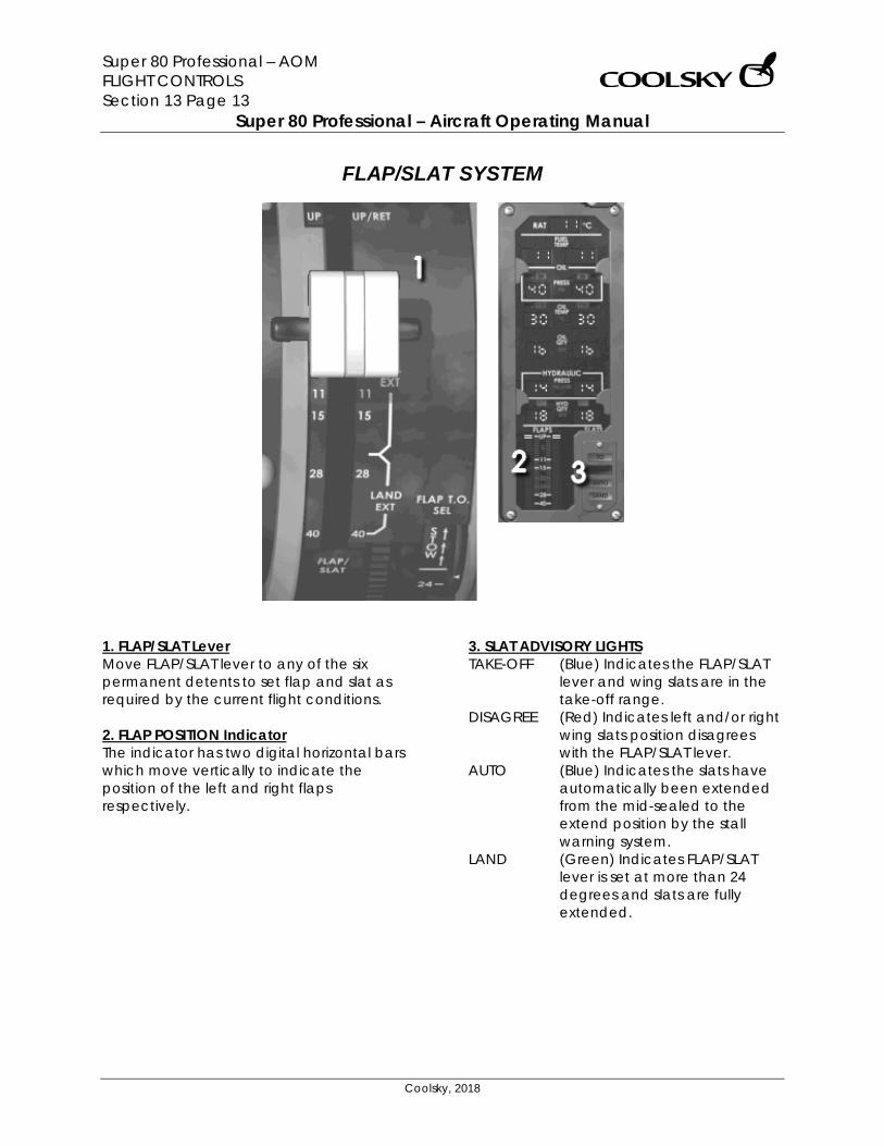
Super 80 Professional – AOM FLIGHT CONTROLS Section 13 Page 13
Super 80 Professional – Aircraft Operating Manual
Coolsky, 2018
FLAP/SLAT SYSTEM
1. FLAP/SLAT Lever Move FLAP/SLAT lever to any of the six permanent detents to set flap and slat as required by the current flight conditions. 2. FLAP POSITION Indicator The indicator has two digital horizontal bars which move vertically to indicate the position of the left and right flaps respectively.
3. SLAT ADVISORY LIGHTS TAKE-OFF (Blue) Indicates the FLAP/SLAT
lever and wing slats are in the take-off range.
DISAGREE (Red) Indicates left and/or right wing slats position disagrees with the FLAP/SLAT lever.
AUTO (Blue) Indicates the slats have automatically been extended from the mid-sealed to the extend position by the stall warning system.
LAND (Green) Indicates FLAP/SLAT lever is set at more than 24 degrees and slats are fully extended.
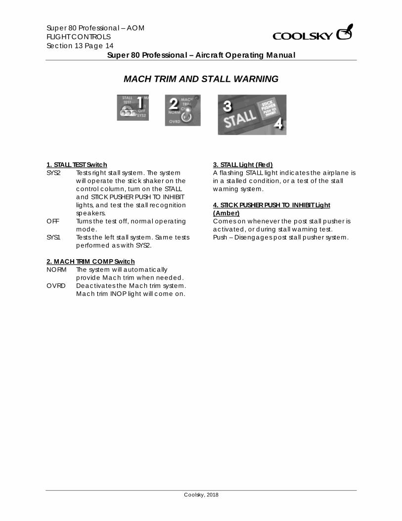
Super 80 Professional – AOM FLIGHT CONTROLS Section 13 Page 14
Super 80 Professional – Aircraft Operating Manual
Coolsky, 2018
MACH TRIM AND STALL WARNING
1. STALL TEST Switch SYS2 Tests right stall system. The system
will operate the stick shaker on the control column, turn on the STALL and STICK PUSHER PUSH TO INHIBIT lights, and test the stall recognition speakers.
OFF Turns the test off, normal operating mode.
SYS1 Tests the left stall system. Same tests performed as with SYS2.
2. MACH TRIM COMP Switch NORM The system will automatically
provide Mach trim when needed. OVRD Deactivates the Mach trim system.
Mach trim INOP light will come on.
3. STALL Light (Red) A flashing STALL light indicates the airplane is in a stalled condition, or a test of the stall warning system. 4. STICK PUSHER PUSH TO INHIBIT Light (Amber) Comes on whenever the post stall pusher is activated, or during stall warning test. Push – Disengages post stall pusher system.
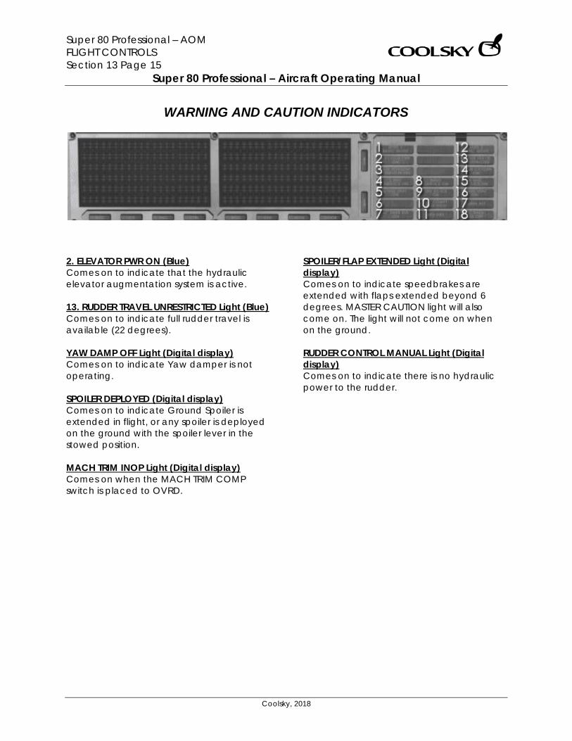
Super 80 Professional – AOM FLIGHT CONTROLS Section 13 Page 15
Super 80 Professional – Aircraft Operating Manual
Coolsky, 2018
WARNING AND CAUTION INDICATORS
2. ELEVATOR PWR ON (Blue) Comes on to indicate that the hydraulic elevator augmentation system is active. 13. RUDDER TRAVEL UNRESTRICTED Light (Blue) Comes on to indicate full rudder travel is available (22 degrees). YAW DAMP OFF Light (Digital display) Comes on to indicate Yaw damper is not operating. SPOILER DEPLOYED (Digital display) Comes on to indicate Ground Spoiler is extended in flight, or any spoiler is deployed on the ground with the spoiler lever in the stowed position. MACH TRIM INOP Light (Digital display) Comes on when the MACH TRIM COMP switch is placed to OVRD.
SPOILER/FLAP EXTENDED Light (Digital display) Comes on to indicate speedbrakes are extended with flaps extended beyond 6 degrees. MASTER CAUTION light will also come on. The light will not come on when on the ground. RUDDER CONTROL MANUAL Light (Digital display) Comes on to indicate there is no hydraulic power to the rudder.
Super 80 Professional – AOM FLIGHT INSTRUMENTS Section 14 Page 0
Super 80 Professional – Aircraft Operating Manual
Coolsky, 2018
SECTION 14
FLIGHT INSTRUMENTS
Super 80 Professional – AOM FLIGHT INSTRUMENTS Section 14 Page 1
Super 80 Professional – Aircraft Operating Manual
Coolsky, 2018
TABLE OF CONTENTS
SECTION 14: FLIGHT INSTRUMENTS 0
TABLE OF CONTENTS ................................................................................................................. 1 GENERAL .................................................................................................................................... 2 AIRSPEED/MACH INDICATOR.................................................................................................. 4 CADC AND STATIC AIR SWITCHING ....................................................................................... 5 TAS/SAT INDICATOR .................................................................................................................. 6 ALTIMETER ................................................................................................................................... 7 RADIO ALTIMETER ...................................................................................................................... 8 SLIP INDICATOR ......................................................................................................................... 8 STANDBY INSTRUMENTS AND CLOCK ..................................................................................... 9 VERTICAL SPEED INDICATOR ................................................................................................. 10 PRIMARY FLIGHT DISPLAY ....................................................................................................... 11 PFD FAIL LEGENDS ................................................................................................................... 13 PFD COMPACTED MODE ....................................................................................................... 14
Super 80 Professional – AOM FLIGHT INSTRUMENTS Section 14 Page 2
Super 80 Professional – Aircraft Operating Manual
Coolsky, 2018
GENERAL Pitot/Static Systems The pitot/static system provides air data sensing to the number 1 and 2 Central Air Data Computer (CADC). The CADC provide outputs of airspeed, Mach, altitude and vertical speed. Three separate pitot/static systems are installed. The Captain’s pitot/static system provides input to CADC 1, the FO’s pitot/static system provides input to CADC 2, and the auxiliary pitot/static system provides input to the standby altimeter and airspeed indicator. The pitot tubes are mounted on top of the nose radome. The static ports are installed on both sides of the fuselage. Primary Flight Instruments The primary flight instruments are the airspeed/Mach indicator, vertical speed indicator, and altimeter. CADC 1 provides input to the Captain’s primary instruments and CADC 2 provides input to the FO’s primary instruments. In the event of a CADC failure, either CADC may be selected to provide input to both the Captain’s and FO’s primary instruments.
Inertial Reference System The Inertial Reference System replaces the directional and vertical gyros providing both navigational and attitude data. Two Inertial Reference Systems are installed in the aircraft. Each IRS contains three laser gyros that sense the angular rate of movement about all three axis. The sensing of angular rate is accomplished by measuring of laser beam shifts within the laser gyro units. Each laser gyro also contains three accelerometers that measure linear acceleration in all three axis. The IRS units provide heading and attitude input to the PFD/ND/RDMI as well as navigation data to the FMS. The present position of the aircraft is determined without any external navigation aids. Data provided by the IRS:
• Attitude • Heading • Acceleration • Ground speed • Track • Present position • Wind direction and velocity
Super 80 Professional – AOM FLIGHT INSTRUMENTS Section 14 Page 3
Super 80 Professional – Aircraft Operating Manual
Coolsky, 2018
Overspeed Warning When the maximum operating airspeed (VMO or MMO) is exceeded, a “clacking” sound followed by the spoken word “overspeed” will be heard from the Central Audio Warning System (CAWS) until airspeed is back within limits. When the airspeed exceeds 280 knots with the slats extended, a “clacking” sound followed by the spoken word “slat overspeed” will be heard from the Central Audio Warning System (CAWS) until airspeed is back below 280 knots or the slats are retracted. Standby Instruments The standby instruments consist of the standby horizon, standby altimeter, standby airspeed indicator and standby magnetic compass. These instruments are powered by the DC transfer bus and should operate at all times, even if a loss of generator power occurs. The standby magnetic compass is currently not simulated. Radio Altimeter The radio altimeter provides radio altitude indications up to a maximum of 2500 feet AGL. During an ILS approach, the radio altimeter will actuate the rising runway symbol on the PFD at approximately 200 feet AGL.
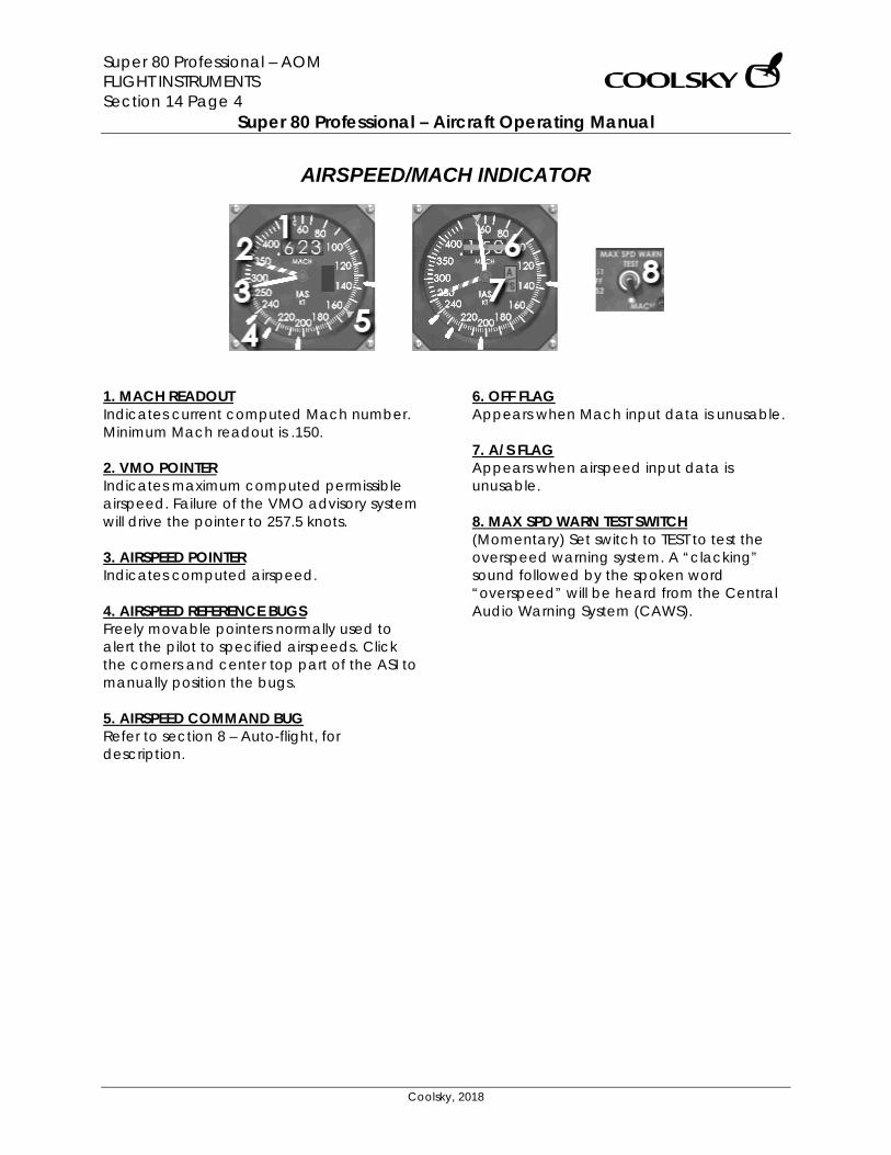
Super 80 Professional – AOM FLIGHT INSTRUMENTS Section 14 Page 4
Super 80 Professional – Aircraft Operating Manual
Coolsky, 2018
AIRSPEED/MACH INDICATOR
1. MACH READOUT Indicates current computed Mach number. Minimum Mach readout is .150. 2. VMO POINTER Indicates maximum computed permissible airspeed. Failure of the VMO advisory system will drive the pointer to 257.5 knots. 3. AIRSPEED POINTER Indicates computed airspeed. 4. AIRSPEED REFERENCE BUGS Freely movable pointers normally used to alert the pilot to specified airspeeds. Click the corners and center top part of the ASI to manually position the bugs. 5. AIRSPEED COMMAND BUG Refer to section 8 – Auto-flight, for description.
6. OFF FLAG Appears when Mach input data is unusable. 7. A/S FLAG Appears when airspeed input data is unusable. 8. MAX SPD WARN TEST SWITCH (Momentary) Set switch to TEST to test the overspeed warning system. A “clacking” sound followed by the spoken word “overspeed” will be heard from the Central Audio Warning System (CAWS).
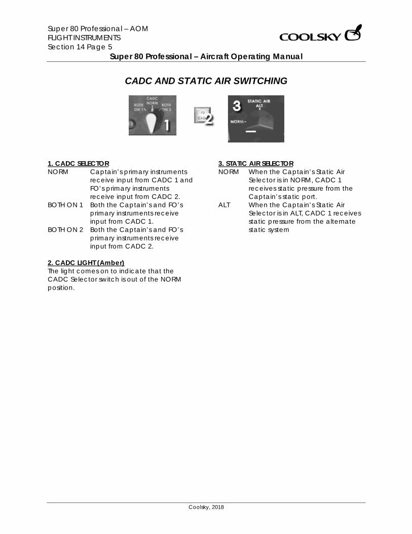
Super 80 Professional – AOM FLIGHT INSTRUMENTS Section 14 Page 5
Super 80 Professional – Aircraft Operating Manual
Coolsky, 2018
CADC AND STATIC AIR SWITCHING
1. CADC SELECTOR NORM Captain’s primary instruments
receive input from CADC 1 and FO’s primary instruments receive input from CADC 2.
BOTH ON 1 Both the Captain’s and FO’s primary instruments receive input from CADC 1.
BOTH ON 2 Both the Captain’s and FO’s primary instruments receive input from CADC 2.
2. CADC LIGHT (Amber) The light comes on to indicate that the CADC Selector switch is out of the NORM position.
3. STATIC AIR SELECTOR NORM When the Captain’s Static Air
Selector is in NORM, CADC 1 receives static pressure from the Captain’s static port.
ALT When the Captain’s Static Air Selector is in ALT, CADC 1 receives static pressure from the alternate static system
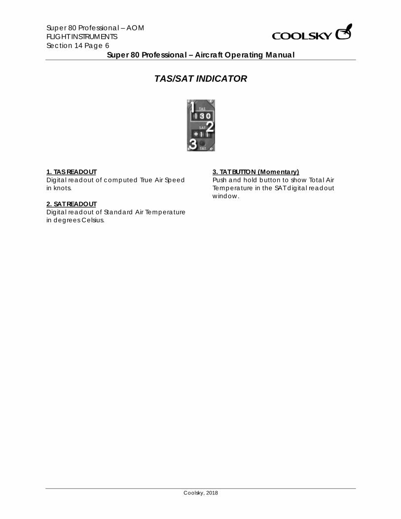
Super 80 Professional – AOM FLIGHT INSTRUMENTS Section 14 Page 6
Super 80 Professional – Aircraft Operating Manual
Coolsky, 2018
TAS/SAT INDICATOR
1. TAS READOUT Digital readout of computed True Air Speed in knots. 2. SAT READOUT Digital readout of Standard Air Temperature in degrees Celsius.
3. TAT BUTTON (Momentary) Push and hold button to show Total Air Temperature in the SAT digital readout window.

Super 80 Professional – AOM FLIGHT INSTRUMENTS Section 14 Page 7
Super 80 Professional – Aircraft Operating Manual
Coolsky, 2018
ALTIMETER
1. ALTITUDE ALERT ADVISORY LIGHT Refer to section 8 – Auto-flight, for description. 2. ALTITUDE REFERENCE INDEX (Orange) The index is set with the Reference Index knob. 3. DIGITAL READOUT The Digital Readout is made with a continuously rotating drum which indicates barometric altitude from -1000 to 50,000 feet. The leftmost number on the drum counter is marked green in the “0” position to alert of altitudes of less than 10,000 feet.
4. 100 FOOT POINTER The pointer will make a full circle for each 1,000 feet of altitude gained or lost. 5. MB/IN HG READOUT Digital readout of the current barometric pressure setting expressed in millibars and inches of mercury. 6. BARO SET KNOB Used to change the barometric pressure setting. 7. REFERENCE INDEX KNOB Used to set altitude reference index.
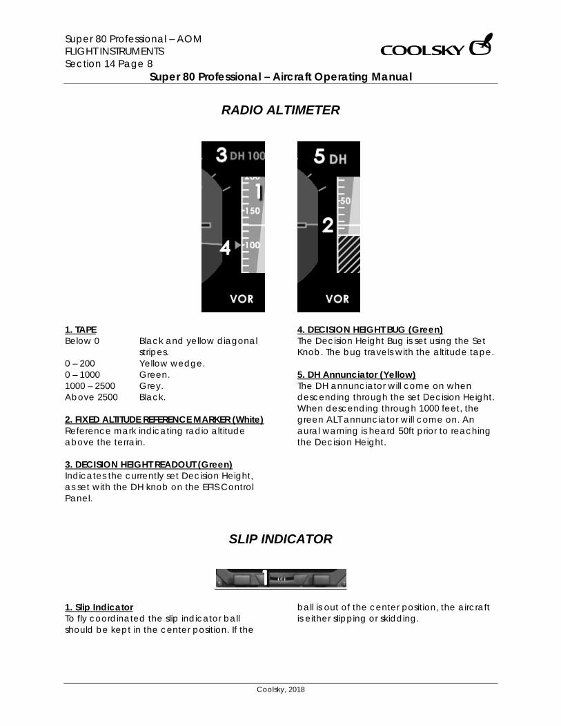
Super 80 Professional – AOM FLIGHT INSTRUMENTS Section 14 Page 8
Super 80 Professional – Aircraft Operating Manual
Coolsky, 2018
RADIO ALTIMETER
1. TAPE Below 0 Black and yellow diagonal
stripes. 0 – 200 Yellow wedge. 0 – 1000 Green. 1000 – 2500 Grey. Above 2500 Black. 2. FIXED ALTITUDE REFERENCE MARKER (White) Reference mark indicating radio altitude above the terrain. 3. DECISION HEIGHT READOUT (Green) Indicates the currently set Decision Height, as set with the DH knob on the EFIS Control Panel.
4. DECISION HEIGHT BUG (Green) The Decision Height Bug is set using the Set Knob. The bug travels with the altitude tape. 5. DH Annunciator (Yellow) The DH annunciator will come on when descending through the set Decision Height. When descending through 1000 feet, the green ALT annunciator will come on. An aural warning is heard 50ft prior to reaching the Decision Height.
SLIP INDICATOR
1. Slip Indicator To fly coordinated the slip indicator ball should be kept in the center position. If the
ball is out of the center position, the aircraft is either slipping or skidding.
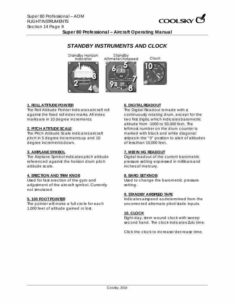
Super 80 Professional – AOM FLIGHT INSTRUMENTS Section 14 Page 9
Super 80 Professional – Aircraft Operating Manual
Coolsky, 2018
STANDBY INSTRUMENTS AND CLOCK
1. ROLL ATTITUDE POINTER The Roll Attitude Pointer indicates aircraft roll against the fixed roll index marks. All index marks are in 10 degree increments. 2. PITCH ATTITUDE SCALE The Pitch Attitude Scale indicates aircraft pitch in 5 degree increments up and 10 degree increments down. 3. AIRPLANE SYMBOL The Airplane Symbol indicates pitch attitude referenced against the horizon drum pitch attitude scale. 4. ERECTION AND TRIM KNOB Used for fast erection of the gyro and adjustment of the aircraft symbol. Currently not simulated. 5. 100 FOOT POINTER The pointer will make a full circle for each 1,000 feet of altitude gained or lost.
6. DIGITAL READOUT The Digital Readout is made with a continuously rotating drum, except for the two first digits, which indicates barometric altitude from -1000 to 50,000 feet. The leftmost number on the drum counter is marked with black and white diagonal stripes in the “0” position to alert of altitudes of less than 10,000 feet. 7. MB/IN HG READOUT Digital readout of the current barometric pressure setting expressed in millibars and inches of mercury. 8. BARO SET KNOB Used to change the barometric pressure setting. 9. STANDBY AIRSPEED TAPE Indicates airspeed as determined from the uncorrected alternate pitot/static inputs. 10. CLOCK Eight-day, stem wound clock with sweep second hand. The clock indicates Zulu time. Click the clock to increase/decrease time.
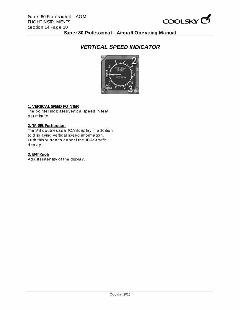
Super 80 Professional – AOM FLIGHT INSTRUMENTS Section 14 Page 10
Super 80 Professional – Aircraft Operating Manual
Coolsky, 2018
VERTICAL SPEED INDICATOR
1. VERTICAL SPEED POINTER The pointer indicates vertical speed in feet per minute. 2. TA SEL Pushbutton The VSI doubles as a TCAS display in addition to displaying vertical speed information. Push this button to cancel the TCAS traffic display. 3. BRT Knob Adjusts intensity of the display.
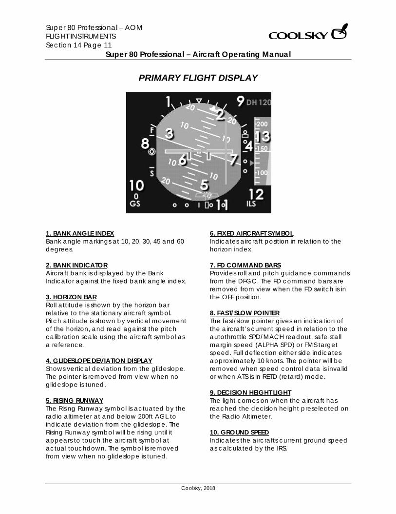
Super 80 Professional – AOM FLIGHT INSTRUMENTS Section 14 Page 11
Super 80 Professional – Aircraft Operating Manual
Coolsky, 2018
PRIMARY FLIGHT DISPLAY
1. BANK ANGLE INDEX Bank angle markings at 10, 20, 30, 45 and 60 degrees. 2. BANK INDICATOR Aircraft bank is displayed by the Bank Indicator against the fixed bank angle index. 3. HORIZON BAR Roll attitude is shown by the horizon bar relative to the stationary aircraft symbol. Pitch attitude is shown by vertical movement of the horizon, and read against the pitch calibration scale using the aircraft symbol as a reference. 4. GLIDESLOPE DEVIATION DISPLAY Shows vertical deviation from the glideslope. The pointer is removed from view when no glideslope is tuned. 5. RISING RUNWAY The Rising Runway symbol is actuated by the radio altimeter at and below 200ft AGL to indicate deviation from the glideslope. The Rising Runway symbol will be rising until it appears to touch the aircraft symbol at actual touchdown. The symbol is removed from view when no glideslope is tuned.
6. FIXED AIRCRAFT SYMBOL Indicates aircraft position in relation to the horizon index. 7. FD COMMAND BARS Provides roll and pitch guidance commands from the DFGC. The FD command bars are removed from view when the FD switch is in the OFF position. 8. FAST/SLOW POINTER The fast/slow pointer gives an indication of the aircraft’s current speed in relation to the autothrottle SPD/MACH readout, safe stall margin speed (ALPHA SPD) or FMS target speed. Full deflection either side indicates approximately 10 knots. The pointer will be removed when speed control data is invalid or when ATS is in RETD (retard) mode. 9. DECISION HEIGHT LIGHT The light comes on when the aircraft has reached the decision height preselected on the Radio Altimeter. 10. GROUND SPEED Indicates the aircrafts current ground speed as calculated by the IRS.
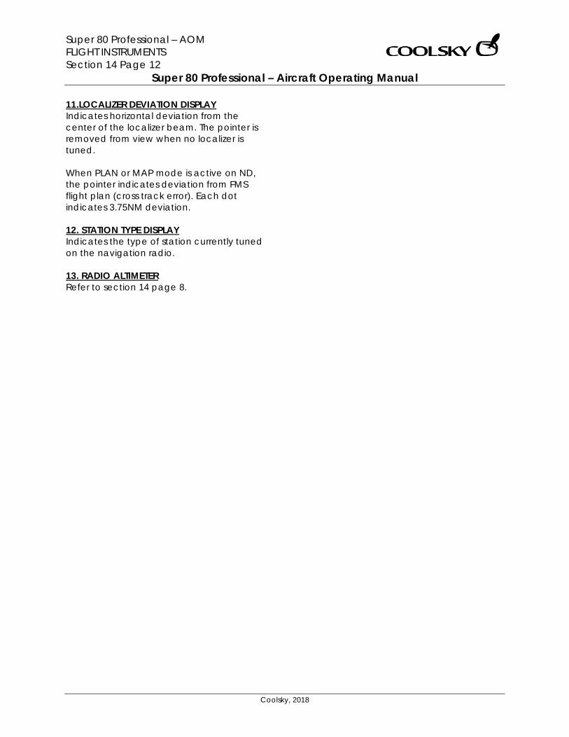
Super 80 Professional – AOM FLIGHT INSTRUMENTS Section 14 Page 12
Super 80 Professional – Aircraft Operating Manual
Coolsky, 2018
11.LOCALIZER DEVIATION DISPLAY Indicates horizontal deviation from the center of the localizer beam. The pointer is removed from view when no localizer is tuned. When PLAN or MAP mode is active on ND, the pointer indicates deviation from FMS flight plan (cross track error). Each dot indicates 3.75NM deviation. 12. STATION TYPE DISPLAY Indicates the type of station currently tuned on the navigation radio. 13. RADIO ALTIMETER Refer to section 14 page 8.
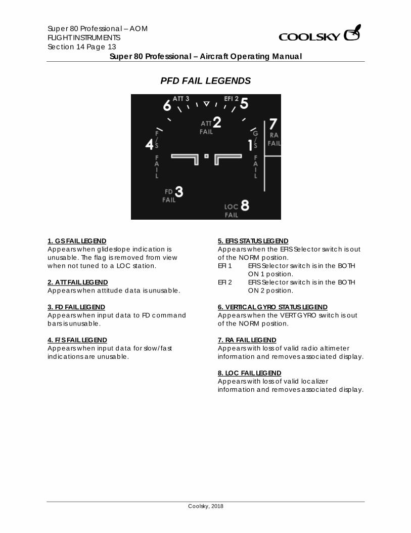
Super 80 Professional – AOM FLIGHT INSTRUMENTS Section 14 Page 13
Super 80 Professional – Aircraft Operating Manual
Coolsky, 2018
PFD FAIL LEGENDS
1. GS FAIL LEGEND Appears when glideslope indication is unusable. The flag is removed from view when not tuned to a LOC station. 2. ATT FAIL LEGEND Appears when attitude data is unusable. 3. FD FAIL LEGEND Appears when input data to FD command bars is unusable. 4. F/S FAIL LEGEND Appears when input data for slow/fast indications are unusable.
5. EFIS STATUS LEGEND Appears when the EFIS Selector switch is out of the NORM position. EFI 1 EFIS Selector switch is in the BOTH
ON 1 position. EFI 2 EFIS Selector switch is in the BOTH
ON 2 position. 6. VERTICAL GYRO STATUS LEGEND Appears when the VERT GYRO switch is out of the NORM position. 7. RA FAIL LEGEND Appears with loss of valid radio altimeter information and removes associated display. 8. LOC FAIL LEGEND Appears with loss of valid localizer information and removes associated display.

Super 80 Professional – AOM FLIGHT INSTRUMENTS Section 14 Page 14
Super 80 Professional – Aircraft Operating Manual
Coolsky, 2018
PFD COMPACTED MODE
1. DIGITAL COURSE READOUT Digital readout of the CRS window and course pointer. 2. DIGITAL HEADING READOUT Digital readout of the HDG window and heading cursor. 3. DME READOUT (2) Digital readout of distance to the tuned navigation radio station. 4. COURSE POINTER In RAD mode, the Course Pointer indicates selected VOR course as set by the CRS select knob on the VHF NAV control panel. In NAV mode, the Course Pointer indicates the desired track to the next waypoint. 5. HEADING CURSOR The Heading Cursor indicates selected heading set by HDG knob on the flight guidance control panel. In NAV mode, the Heading Cursor indicates the actual track over the ground.
6.LOCALIZER DEVIATION DISPLAY Indicates horizontal deviation from the center of the localizer beam. The pointer is removed from view when no localizer is tuned. 7. TO/FROM ANNUNCIATOR Indicates direction TO or FROM the selected radio navigation station along selected course. 8. STATION TYPE DISPLAY Indicates the type of station currently tuned on the navigation radio.
Super 80 Professional – AOM FLIGHT MANAGEMENT Section 15 Page 0
Super 80 Professional – Aircraft Operating Manual
Coolsky, 2018
SECTION 15
FLIGHT MANAGEMENT

Super 80 Professional – AOM FLIGHT MANAGEMENT Section 15 Page 1
Super 80 Professional – Aircraft Operating Manual
Coolsky, 2018
TABLE OF CONTENTS
SECTION 15: FLIGHT MANAGEMENT 0
TABLE OF CONTENTS ................................................................................................................. 1 GENERAL .................................................................................................................................... 2 IRS MODE SELECT PANEL .......................................................................................................... 6 FMS FLIGHT GUIDANCE MODES .............................................................................................. 7 MCDU PAGE DESCRIPTION .................................................................................................... 11
Menu Page ...................................................................................................................... 11 Initialization Reference Index Page .............................................................................. 11 Identification Page ......................................................................................................... 12 Position Initialization Page .............................................................................................. 12 Performance Initialization Page .................................................................................... 14 Takeoff Reference Page ................................................................................................ 15 Approach Reference Page ........................................................................................... 16 Reference Navigation Data Page ................................................................................ 17 Route Page ...................................................................................................................... 18 Legs Page......................................................................................................................... 21 Legs Page (Continued) ................................................................................................. 22 Legs Page (Continued) .................................................................................................. 23 Direct To/Intercept Leg To ............................................................................................. 24 Route Data/Select Desired Waypoint .......................................................................... 25 Hold ................................................................................................................................... 26 Departure/Arrival Index .................................................................................................. 28 Departures ....................................................................................................................... 29 Arrivals ............................................................................................................................... 30 Progress............................................................................................................................. 31 Fix Information .................................................................................................................. 33 Climb ................................................................................................................................. 34 Cruise ................................................................................................................................ 35 Descent ............................................................................................................................ 37 Descent Forecast ............................................................................................................ 39
FMS OPERATIONS .................................................................................................................... 40 IRS Operation ................................................................................................................... 40 FMS Initialization ............................................................................................................... 41 FMS Lateral Navigation ................................................................................................... 43 FMS Vertical Navigation ................................................................................................. 48 FMS Progress Functions ................................................................................................... 50 FMS Performance Data Entry ......................................................................................... 51
Super 80 Professional – AOM FLIGHT MANAGEMENT Section 15 Page 2
Super 80 Professional – Aircraft Operating Manual
Coolsky, 2018
GENERAL
Overview The Flight Management System (FMS), in conjunction with other interfacing equipment on the aircraft, provides automatic navigation guidance, map display, and in-flight performance optimization. The FMS eliminates many routine tasks and computation normally performed by the flight crew. FMS Functions The major functions of the integrated FMS are:
• Storage of navigation data, aerodynamic and engine data.
• Means for entry, storage, and in-flight modification of a complete flight plan from the departure gate to the destination runway.
• Computations of the optimum vertical profile based on pilot entries and the performance database.
• Storage and transmission of data to generate maps of the route on the EFIS ND.
• Calculation of the aircraft’s position and transmission of this information for display on the EFIS ND.
• Automatic selection and tuning of DME stations for accurate estimation of aircraft position.
FMS Components The FMS consists of one Advanced Flight Management Computer (AFMC), and two Multipurpose Control and Display Units (MCDU).
The AFMC receives input from a number of sources to compute navigation and performance information:
• Attitude Heading Reference System (AHRS) provides heading, attitude and acceleration data.
• Inertial Reference System (IRS) provides position and velocity data.
• Captain’s digital clock provides GMT data.
• Central Air Data Computer (CADC) provides airspeed, vertical speed and pressure altitude data.
• DME provides data for estimating aircraft position.
• VHF stations provide data for estimating aircraft position.
• Digital Flight Guidance Computer (DFGC) provides vertical accelerations and attitudes (pitch and roll).
AFMC Database The AFMC database is divided in two major sections:
• Performance data: o Airplane drag and engine
characteristics. o Optimal speed data. o Maximum and minimum
speeds. • Navigation data:
o Published airways, intersections and navaids.
o Airports, runways, SIDs and STARs.
The AFMC navigation database is updated by maintenance every 28 days.
Super 80 Professional – AOM FLIGHT MANAGEMENT Section 15 Page 3
Super 80 Professional – Aircraft Operating Manual
Coolsky, 2018
FMS Special Commands You can enter special commands into the scratchpad to have the FMS perform various tasks. RESET This feature completely resets the FMS. It will delete all data and restores default startup values. Example: Enter ‘RESET’ into the scratchpad and press enter on the keyboard or press the EXEC key on the FMS. SAVE Use this feature when you wish save your FMS data in order to resume the flight at a later time. Enter SAVE followed by a filename (separated by space) to save all FMS data to a file. The flight plan and all entered data will be saved. Example: Enter ‘SAVE VHHH-ZSSS-2’ into the scratchpad and press enter on the keyboard or press the EXEC key on the FMS. FMS data files are saved in the default P3D flight plan folder with a *.FMS80 extension. LOAD Use this feature when you wish to resume a saved flight. Note that this feature will not only load the flight plan but all the FMS data as saved with the SAVE feature above. This feature will not load a P3D flight plan file. It will only load data files saved with the SAVE feature. Enter LOAD followed by a filename (separated by space) to load saved FMS data from a file. Example: “LOAD VHHH-ZSSS-2”. Example: Enter ‘LOAD VHHH-ZSSS-2’ into the scratchpad and press enter on the keyboard or press the EXEC key on the FMS.
Loading a P3D flight plan into the FMS You can load a P3D flight plan into the FMS by entering the flight plan filename into the Company route (CO ROUTE) entry field on the Route page. Enter the name of the flight plan you wish to load without the .PLN suffix. The FMS has a limited character set compared to your computer keyboard. The FMS can only load flight plans using the FMS keyboard character set. Make sure you save your flight plan using the characters available on the FMS keyboard. The flight plan name can have a maximum of 24 characters. Valid example: Flight plan 001.PLN KLAX to KDEN.PLN ESSA-EKCH-1.PLN These example flight plans would be entered into the CO ROUTE entry field as: Flight plan 001 KLAX to KDEN ESSA-EKCH-1 Invalid example: KORD_KMIA_001.PLN (use of underscore) The FMS will search for the entered flight plan in the standard P3D flight plan folder by default. You can change the search path/folder manually by setting the ‘fms_flightplan_path’ variable in the Super80Pro.ini file. Example: fms_flightplan_path=c:\P3Ddata\FlightPlans fms_flightplan_path=\\NETWORK-PC1\fplan
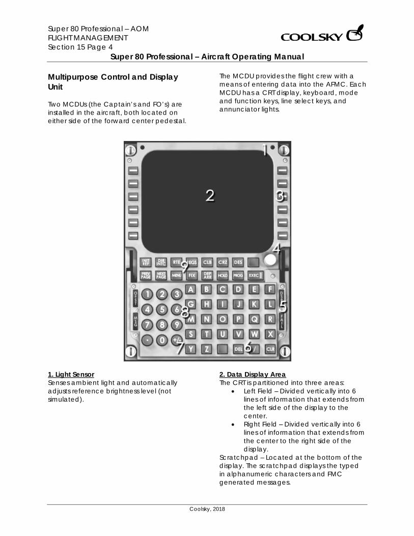
Super 80 Professional – AOM FLIGHT MANAGEMENT Section 15 Page 4
Super 80 Professional – Aircraft Operating Manual
Coolsky, 2018
Multipurpose Control and Display Unit Two MCDUs (the Captain’s and FO’s) are installed in the aircraft, both located on either side of the forward center pedestal.
The MCDU provides the flight crew with a means of entering data into the AFMC. Each MCDU has a CRT display, keyboard, mode and function keys, line select keys, and annunciator lights.
1. Light Sensor Senses ambient light and automatically adjusts reference brightness level (not simulated).
2. Data Display Area The CRT is partitioned into three areas:
• Left Field – Divided vertically into 6 lines of information that extends from the left side of the display to the center.
• Right Field – Divided vertically into 6 lines of information that extends from the center to the right side of the display.
Scratchpad – Located at the bottom of the display. The scratchpad displays the typed in alphanumeric characters and FMC generated messages.
Super 80 Professional – AOM FLIGHT MANAGEMENT Section 15 Page 5
Super 80 Professional – Aircraft Operating Manual
Coolsky, 2018
3. Line Select Keys (LSK) The LSK provides for the entry, selection, or deletion of information on an adjacent line on the display.
• Entry – Moves information to the selected line from the scratchpad.
• Selection – Selects a page, procedure, or performance mode as required.
• Deletion – Deletes information on the selected line after pushing the DEL key.
4. BRT Knob Manually adjusts the brightness of the CRT. 5. Message Lights MENU Illuminates when any non active
subsystem has a request pending (not simulated).
MSG Illuminates when the FMS generates a message displayed in the scratchpad.
DSPY Illuminates when the current display is not related to the active leg or current performance mode.
OFST Illuminates when the aircraft is flying a parallel offset of the active flight plan (not simulated).
6. Miscellaneous Keys CLR Push to clear the scratchpad. / Used as a data separator. DEL Push to delete the data in the data
field if allowed. 7. +/- Key All numeric entries into the scratchpad are assumed to be positive. If a negative values is required, pushing the key enters a minus. Pushing the key a second time changes to a plus. 8. Alpha/Numeric Keys Push to enter selected character into the scratchpad.
9. Function Keys EXEC Command key of the FMS. Push
to implement changes to the active flight plan.
NEXT PAGE Displays the next page for multiple pages.
PREV PAGE Displays the previous page for multiple pages.
INIT REF Selects the POS INIT page for initialization if position is not set. Selects the PERF INIT page for initialization if performance data is not set. Selects the APPROACH REF page in-flight.
RTE Selects RTE1 and RTE2 pages. DIR INTC Selects the page for flying
direct to, or intercept a course to any on or off-route waypoint while on the active leg.
HOLD Allows definition of a holding pattern at any desired waypoint or at the aircraft present position.
LEGS Provides detailed data concerning every leg of a flight plan and allows data to be entered and deleted for each leg.
DEP ARR Provides for selection of departure and/or arrival procedures and runways.
PROG Displays current dynamic flight information such as distance to go, cross track error, fuel, wind, etc.
FIX Allows creation of waypoint fixes from the intersection points between present route and the selected radials from known waypoints.
CLB Displays current or planned climb mode.
CRZ Displays current or planned climb mode.
DES Displays current or planned descent mode.
MENU Selects MENU page to select a subsystem.
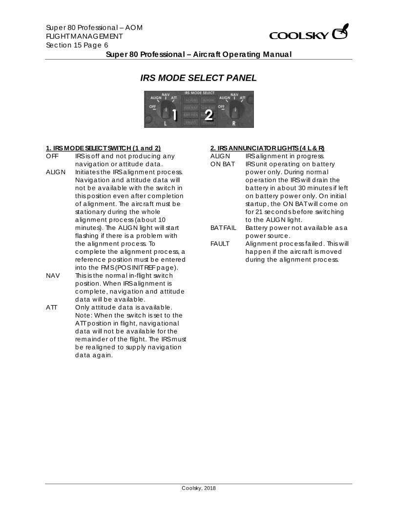
Super 80 Professional – AOM FLIGHT MANAGEMENT Section 15 Page 6
Super 80 Professional – Aircraft Operating Manual
Coolsky, 2018
IRS MODE SELECT PANEL
1. IRS MODE SELECT SWITCH (1 and 2) OFF IRS is off and not producing any
navigation or attitude data. ALIGN Initiates the IRS alignment process.
Navigation and attitude data will not be available with the switch in this position even after completion of alignment. The aircraft must be stationary during the whole alignment process (about 10 minutes). The ALIGN light will start flashing if there is a problem with the alignment process. To complete the alignment process, a reference position must be entered into the FMS (POS INIT REF page).
NAV This is the normal in-flight switch position. When IRS alignment is complete, navigation and attitude data will be available.
ATT Only attitude data is available. Note: When the switch is set to the ATT position in flight, navigational data will not be available for the remainder of the flight. The IRS must be realigned to supply navigation data again.
2. IRS ANNUNCIATOR LIGHTS (4 L & R) ALIGN IRS alignment in progress. ON BAT IRS unit operating on battery
power only. During normal operation the IRS will drain the battery in about 30 minutes if left on battery power only. On initial startup, the ON BAT will come on for 21 seconds before switching to the ALIGN light.
BAT FAIL Battery power not available as a power source.
FAULT Alignment process failed. This will happen if the aircraft is moved during the alignment process.
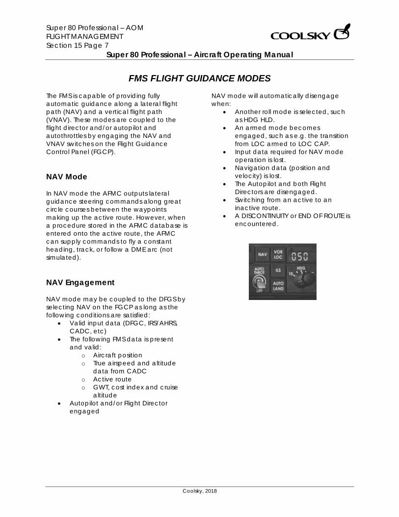
Super 80 Professional – AOM FLIGHT MANAGEMENT Section 15 Page 7
Super 80 Professional – Aircraft Operating Manual
Coolsky, 2018
FMS FLIGHT GUIDANCE MODES The FMS is capable of providing fully automatic guidance along a lateral flight path (NAV) and a vertical flight path (VNAV). These modes are coupled to the flight director and/or autopilot and autothrottles by engaging the NAV and VNAV switches on the Flight Guidance Control Panel (FGCP). NAV Mode In NAV mode the AFMC outputs lateral guidance steering commands along great circle courses between the waypoints making up the active route. However, when a procedure stored in the AFMC database is entered onto the active route, the AFMC can supply commands to fly a constant heading, track, or follow a DME arc (not simulated). NAV Engagement NAV mode may be coupled to the DFGS by selecting NAV on the FGCP as long as the following conditions are satisfied:
• Valid input data (DFGC, IRS/AHRS, CADC, etc)
• The following FMS data is present and valid:
o Aircraft position o True airspeed and altitude
data from CADC o Active route o GWT, cost index and cruise
altitude • Autopilot and/or Flight Director
engaged
NAV mode will automatically disengage when:
• Another roll mode is selected, such as HDG HLD.
• An armed mode becomes engaged, such as e.g. the transition from LOC armed to LOC CAP.
• Input data required for NAV mode operation is lost.
• Navigation data (position and velocity) is lost.
• The Autopilot and both Flight Directors are disengaged.
• Switching from an active to an inactive route.
• A DISCONTINUITY or END OF ROUTE is encountered.
Super 80 Professional – AOM FLIGHT MANAGEMENT Section 15 Page 8
Super 80 Professional – Aircraft Operating Manual
Coolsky, 2018
NAV Mode Holding The FMS will provide automatic flight guidance for entering and flying a holding pattern. When a holding pattern has been programmed into the active route, the ND MAP or PLN mode will display the holding pattern. When coupled to the autopilot, flight director, and autothrottles, the system will enter and fly the pattern. Construction of Holding Pattern The HOLD page offers the flight crew to construct a holding pattern at the aircraft’s present position or at any enroute waypoint. Additionally, the flight crew may specify the holding radial, direction of turns, leg length or time, and holding speed and altitude. If not modified the HOLD page will default to the following values:
• Direction of inbound course equals course along the active route of flight to the holding fix.
• Leg length defaults to: o 1 minute at or below 14,000ft o 1.5 minutes above 14,000ft
• Direction of turns default to right turns.
• FMS hold speed will default to the higher of 1.5 VS clean and the minimum 1.25 G buffet speed.
Holding Pattern Entry The aircraft must first pass the holding waypoint before entering the holding pattern. The FMS will use three types of hold entry depending on the entry angle:
1. Direct entry 2. Teardrop 3. Parallel
Holding Pattern Exit The flight crew may exit the holding pattern by either of two methods:
• Select and execute the EXIT HOLD prompt on the HOLD page. The AFMC will provide guidance back to the holding waypoint and then continue flight along the remainder of the active route.
• Change the route by other means; changing the active waypoint on the DIR/INTC page or selecting a roll mode other than NAV.
VNAV Mode In VNAV AFMC provides vertical guidance and speed/thrust control through all phases of flight; climb, cruise and descent. VNAV Mode – Climb During climb, the AFMC will control the aircraft to climb at climb limit thrust to each altitude constraint, fly level at cruise thrust until past the constraining waypoint, and the resume the climb at climb limit thrust. The normal VNAV speed schedule is 250kts below 10,000ft, and then economy speed above 10,000ft. Economy speed is a function of gross weight at Top of Climb (TC), entered cruise altitude, and cost index. VNAV Mode – Cruise The FMS will default to economy speed until the Top of Descent (TD) point. The flight crew may enter other speeds/mach on the CRZ page.
Super 80 Professional – AOM FLIGHT MANAGEMENT Section 15 Page 9
Super 80 Professional – Aircraft Operating Manual
Coolsky, 2018
VNAV Mode – Descent The AFMC will calculate a descent path when the flight crew has entered an End of Descent (ED) point. The ED point is a waypoint altitude constraint that requires a descent from the cruise altitude. An ED point may be set by entering an altitude constraint for a waypoint on the LEGS page, or by selecting STAR/approach procedure on the DEP/ARR page. The AFMC computes the descent path by starting at the ED point and projecting back up to the cruise altitude. The point where this path intersects with the cruise attitude is the Top of Descent (TD) point. When reaching the TD point, the AFMC will command idle thrust and pitch down to follow the descent path, provided the FGCP altitude pre-select readout is set to a lower altitude than the aircraft’s current altitude. The flight crew may initiate VNAV descent prior to the TD point by selecting and executing the DES NOW prompt on the DES page. The aircraft will not descent below the altitude set in the altitude pre-select readout. The descent path to the first altitude constraint assumes idle thrust, retracted speed brakes, decreasing wind speed, and the AFMC target airspeed. The AFMC defaults to economy speed above 10,000ft and 240kts below 10,000ft. The flight crew may alter the decent profile calculated by entering forecast winds, anti-ice requirements (not simulated), or changing the target speed. For deviation below the vertical profile, the FMS will make corrections through throttle commands. For deviation above the vertical profile, the FMS will increase the airspeed (throttles idle) 10 to 15kts above target airspeed and a DRAG REQUIRED message will be displayed in the MCDU scratchpad.
FMS Speed Override The FMS override features allows the flight crew to manually set the speed while remaining in VNAV mode. The FMS override mode is engaged by pushing the FMS OVRD button on the FGCP. When in the FMS override mode, the Speed/Mach Select Knob on the FGCP allows selection of the desired speed. When in the FMS override mode:
• The selected speed is displayed in the FGCP Speed/Mach Readout.
• The FMS throttle window annunciates OVRD followed by the selected speed.
• PROGRESS page 1, line 5L will read OVRD SPD.
To disengage the FMS override mode, push the FMS OVRD again. VNAV Engagement The flight crew may couple the FMS VNAV mode to the DFGS by pushing the VNAV button on the FGCP as long as the following conditions are satisfied:
• The following FMS data is present: o Aircraft GWT, cost index,
cruise altitude. o Aircraft position, CADC data,
IAS, Mach, SAT, TAT, pressure altitude, and vertical speed.
o Roll and pitch attitudes. o FGCP clearance altitude
(altitude preselect readout). o Acceleration data. o Vertical flight plan.
• Autopilot and/or Flight Director engaged.
• TRP is not in TO, TO FLX, or GA mode. • The autothrottles are engaged or will
be engaged within 5 seconds of VNAV engagement.
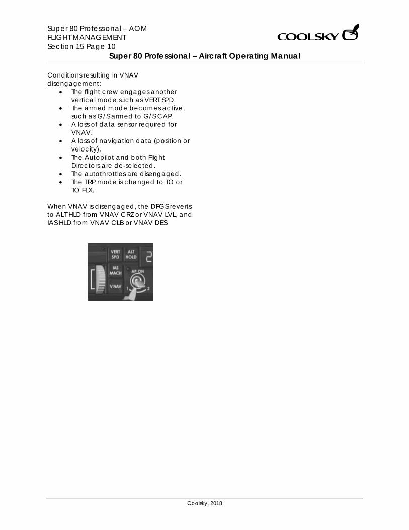
Super 80 Professional – AOM FLIGHT MANAGEMENT Section 15 Page 10
Super 80 Professional – Aircraft Operating Manual
Coolsky, 2018
Conditions resulting in VNAV disengagement:
• The flight crew engages another vertical mode such as VERT SPD.
• The armed mode becomes active, such as G/S armed to G/S CAP.
• A loss of data sensor required for VNAV.
• A loss of navigation data (position or velocity).
• The Autopilot and both Flight Directors are de-selected.
• The autothrottles are disengaged. • The TRP mode is changed to TO or
TO FLX. When VNAV is disengaged, the DFGS reverts to ALT HLD from VNAV CRZ or VNAV LVL, and IAS HLD from VNAV CLB or VNAV DES.
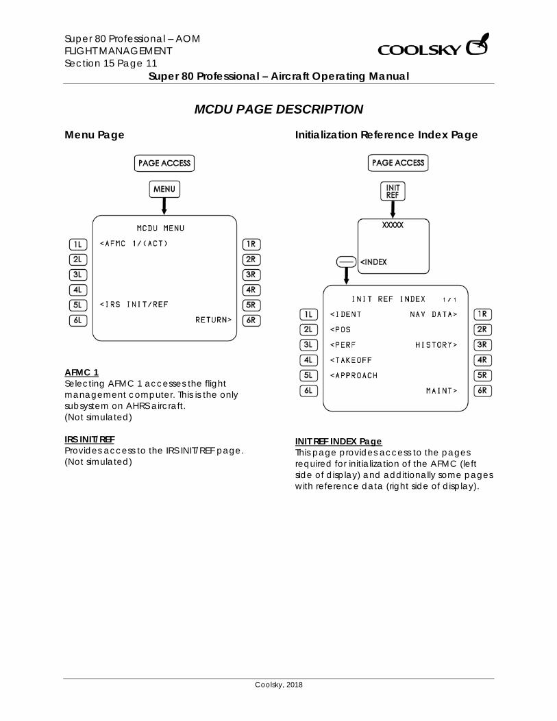
Super 80 Professional – AOM FLIGHT MANAGEMENT Section 15 Page 11
Super 80 Professional – Aircraft Operating Manual
Coolsky, 2018
MCDU PAGE DESCRIPTION Menu Page
AFMC 1 Selecting AFMC 1 accesses the flight management computer. This is the only subsystem on AHRS aircraft. (Not simulated) IRS INIT/REF Provides access to the IRS INIT/REF page. (Not simulated)
Initialization Reference Index Page
INIT REF INDEX Page This page provides access to the pages required for initialization of the AFMC (left side of display) and additionally some pages with reference data (right side of display).
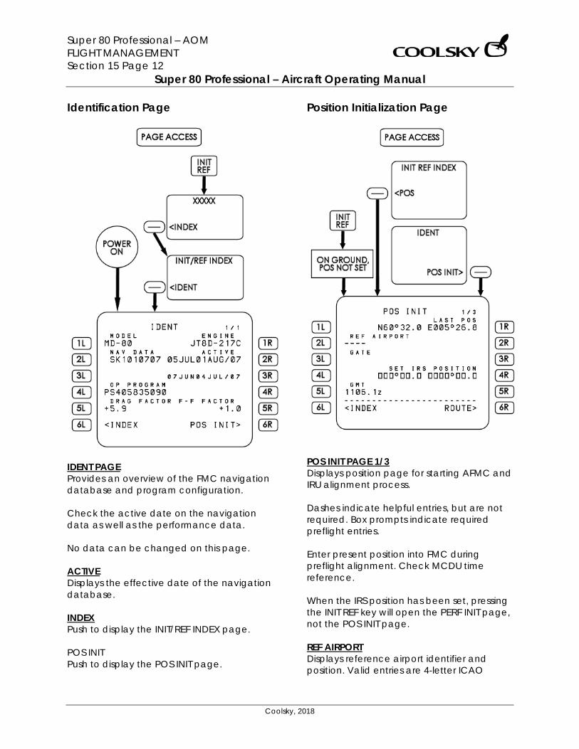
Super 80 Professional – AOM FLIGHT MANAGEMENT Section 15 Page 12
Super 80 Professional – Aircraft Operating Manual
Coolsky, 2018
Identification Page
IDENT PAGE Provides an overview of the FMC navigation database and program configuration. Check the active date on the navigation data as well as the performance data. No data can be changed on this page. ACTIVE Displays the effective date of the navigation database. INDEX Push to display the INIT/REF INDEX page. POS INIT Push to display the POS INIT page.
Position Initialization Page
POS INIT PAGE 1/3 Displays position page for starting AFMC and IRU alignment process. Dashes indicate helpful entries, but are not required. Box prompts indicate required preflight entries. Enter present position into FMC during preflight alignment. Check MCDU time reference. When the IRS position has been set, pressing the INIT REF key will open the PERF INIT page, not the POS INIT page. REF AIRPORT Displays reference airport identifier and position. Valid entries are 4-letter ICAO
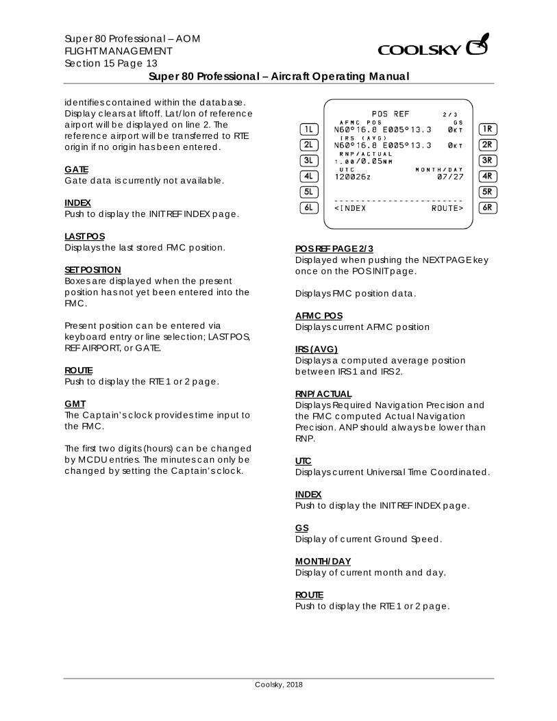
Super 80 Professional – AOM FLIGHT MANAGEMENT Section 15 Page 13
Super 80 Professional – Aircraft Operating Manual
Coolsky, 2018
identifies contained within the database. Display clears at liftoff. Lat/lon of reference airport will be displayed on line 2. The reference airport will be transferred to RTE origin if no origin has been entered. GATE Gate data is currently not available. INDEX Push to display the INIT REF INDEX page. LAST POS Displays the last stored FMC position. SET POSITION Boxes are displayed when the present position has not yet been entered into the FMC. Present position can be entered via keyboard entry or line selection; LAST POS, REF AIRPORT, or GATE. ROUTE Push to display the RTE 1 or 2 page. GMT The Captain’s clock provides time input to the FMC. The first two digits (hours) can be changed by MCDU entries. The minutes can only be changed by setting the Captain’s clock.
POS REF PAGE 2/3 Displayed when pushing the NEXT PAGE key once on the POS INIT page. Displays FMC position data. AFMC POS Displays current AFMC position IRS (AVG) Displays a computed average position between IRS 1 and IRS 2. RNP/ACTUAL Displays Required Navigation Precision and the FMC computed Actual Navigation Precision. ANP should always be lower than RNP. UTC Displays current Universal Time Coordinated. INDEX Push to display the INIT REF INDEX page. GS Display of current Ground Speed. MONTH/DAY Display of current month and day. ROUTE Push to display the RTE 1 or 2 page.
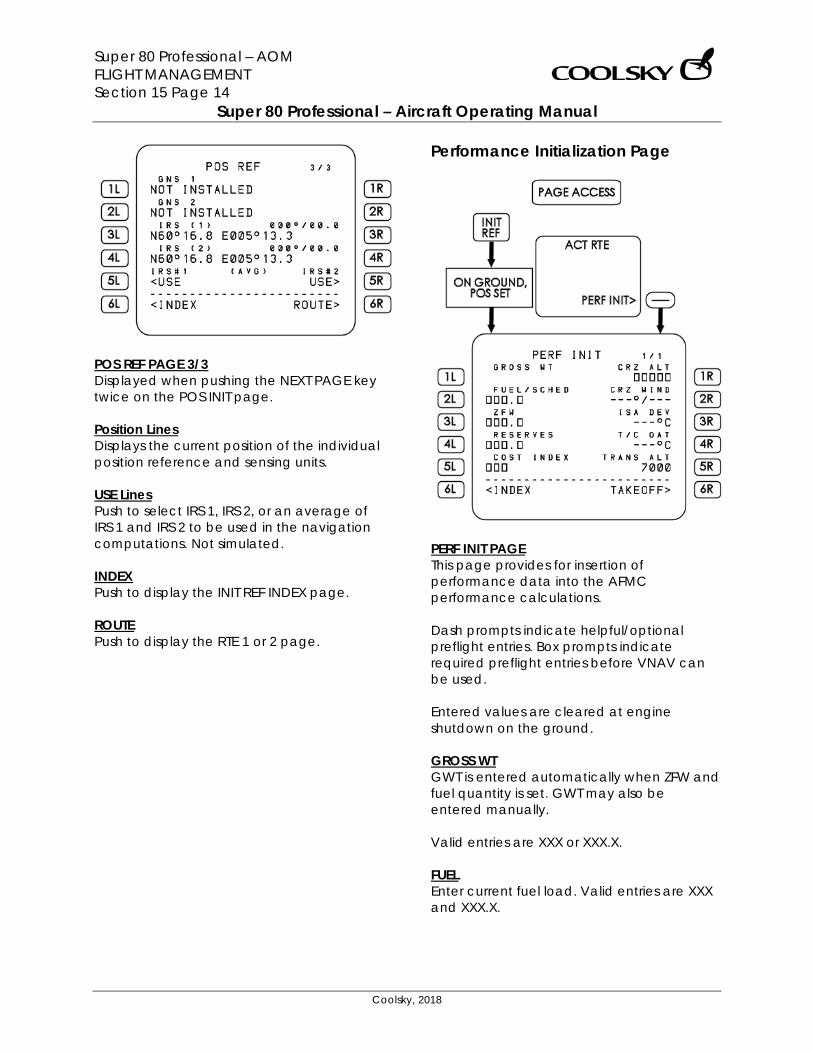
Super 80 Professional – AOM FLIGHT MANAGEMENT Section 15 Page 14
Super 80 Professional – Aircraft Operating Manual
Coolsky, 2018
POS REF PAGE 3/3 Displayed when pushing the NEXT PAGE key twice on the POS INIT page. Position Lines Displays the current position of the individual position reference and sensing units. USE Lines Push to select IRS 1, IRS 2, or an average of IRS 1 and IRS 2 to be used in the navigation computations. Not simulated. INDEX Push to display the INIT REF INDEX page. ROUTE Push to display the RTE 1 or 2 page.
Performance Initialization Page
PERF INIT PAGE This page provides for insertion of performance data into the AFMC performance calculations. Dash prompts indicate helpful/optional preflight entries. Box prompts indicate required preflight entries before VNAV can be used. Entered values are cleared at engine shutdown on the ground. GROSS WT GWT is entered automatically when ZFW and fuel quantity is set. GWT may also be entered manually. Valid entries are XXX or XXX.X. FUEL Enter current fuel load. Valid entries are XXX and XXX.X.
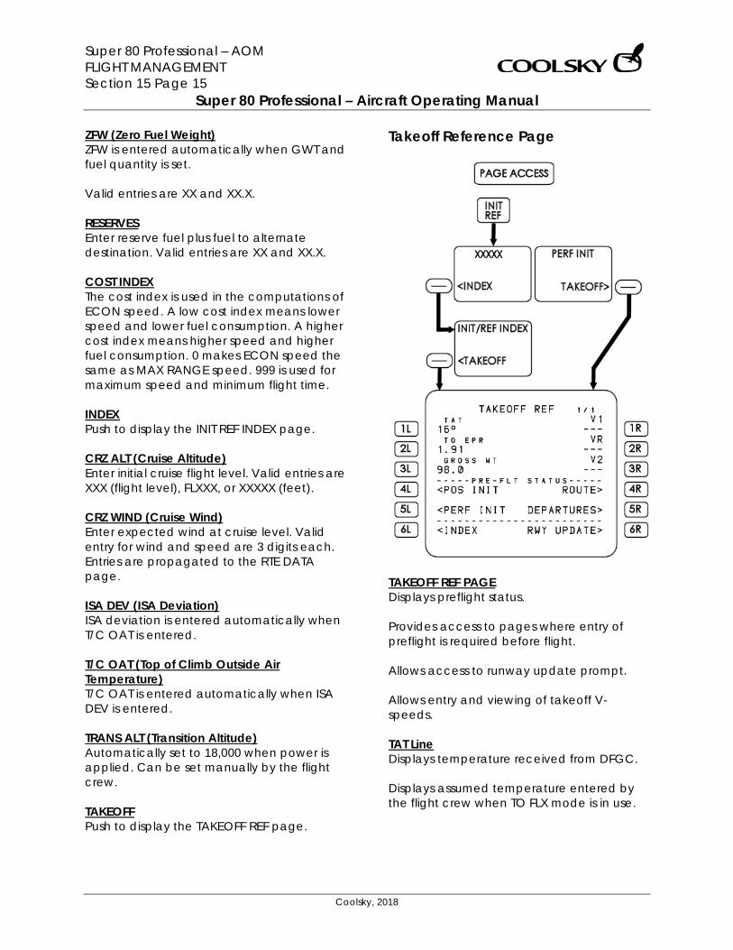
Super 80 Professional – AOM FLIGHT MANAGEMENT Section 15 Page 15
Super 80 Professional – Aircraft Operating Manual
Coolsky, 2018
ZFW (Zero Fuel Weight) ZFW is entered automatically when GWT and fuel quantity is set. Valid entries are XX and XX.X. RESERVES Enter reserve fuel plus fuel to alternate destination. Valid entries are XX and XX.X. COST INDEX The cost index is used in the computations of ECON speed. A low cost index means lower speed and lower fuel consumption. A higher cost index means higher speed and higher fuel consumption. 0 makes ECON speed the same as MAX RANGE speed. 999 is used for maximum speed and minimum flight time. INDEX Push to display the INIT REF INDEX page. CRZ ALT (Cruise Altitude) Enter initial cruise flight level. Valid entries are XXX (flight level), FLXXX, or XXXXX (feet). CRZ WIND (Cruise Wind) Enter expected wind at cruise level. Valid entry for wind and speed are 3 digits each. Entries are propagated to the RTE DATA page. ISA DEV (ISA Deviation) ISA deviation is entered automatically when T/C OAT is entered. T/C OAT (Top of Climb Outside Air Temperature) T/C OAT is entered automatically when ISA DEV is entered. TRANS ALT (Transition Altitude) Automatically set to 18,000 when power is applied. Can be set manually by the flight crew. TAKEOFF Push to display the TAKEOFF REF page.
Takeoff Reference Page
TAKEOFF REF PAGE Displays preflight status. Provides access to pages where entry of preflight is required before flight. Allows access to runway update prompt. Allows entry and viewing of takeoff V-speeds. TAT Line Displays temperature received from DFGC. Displays assumed temperature entered by the flight crew when TO FLX mode is in use.
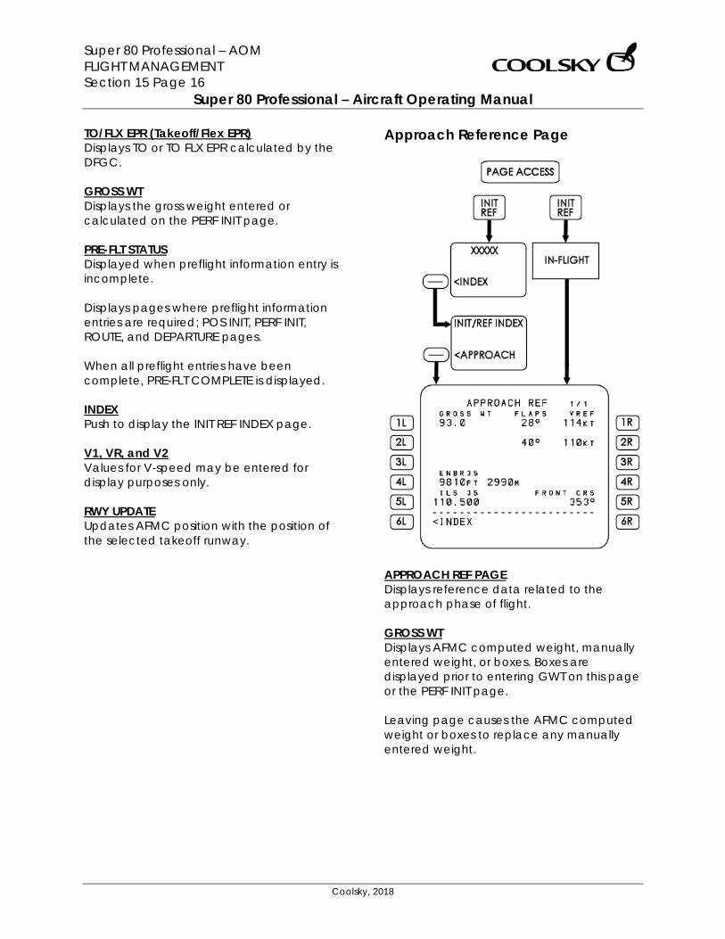
Super 80 Professional – AOM FLIGHT MANAGEMENT Section 15 Page 16
Super 80 Professional – Aircraft Operating Manual
Coolsky, 2018
TO/FLX EPR (Takeoff/Flex EPR) Displays TO or TO FLX EPR calculated by the DFGC. GROSS WT Displays the gross weight entered or calculated on the PERF INIT page. PRE-FLT STATUS Displayed when preflight information entry is incomplete. Displays pages where preflight information entries are required; POS INIT, PERF INIT, ROUTE, and DEPARTURE pages. When all preflight entries have been complete, PRE-FLT COMPLETE is displayed. INDEX Push to display the INIT REF INDEX page. V1, VR, and V2 Values for V-speed may be entered for display purposes only. RWY UPDATE Updates AFMC position with the position of the selected takeoff runway.
Approach Reference Page
APPROACH REF PAGE Displays reference data related to the approach phase of flight. GROSS WT Displays AFMC computed weight, manually entered weight, or boxes. Boxes are displayed prior to entering GWT on this page or the PERF INIT page. Leaving page causes the AFMC computed weight or boxes to replace any manually entered weight.
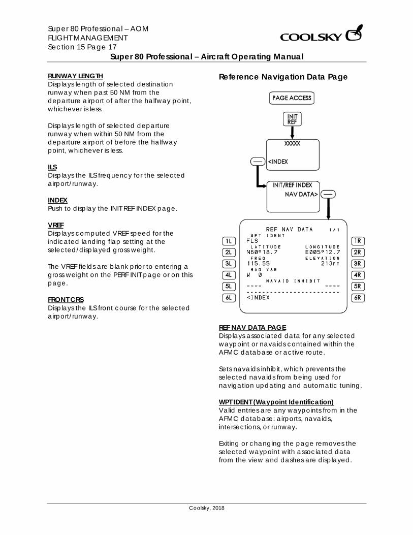
Super 80 Professional – AOM FLIGHT MANAGEMENT Section 15 Page 17
Super 80 Professional – Aircraft Operating Manual
Coolsky, 2018
RUNWAY LENGTH Displays length of selected destination runway when past 50 NM from the departure airport of after the halfway point, whichever is less. Displays length of selected departure runway when within 50 NM from the departure airport of before the halfway point, whichever is less. ILS Displays the ILS frequency for the selected airport/runway. INDEX Push to display the INIT REF INDEX page. VREF Displays computed VREF speed for the indicated landing flap setting at the selected/displayed gross weight. The VREF fields are blank prior to entering a gross weight on the PERF INIT page or on this page. FRONT CRS Displays the ILS front course for the selected airport/runway.
Reference Navigation Data Page
REF NAV DATA PAGE Displays associated data for any selected waypoint or navaids contained within the AFMC database or active route. Sets navaids inhibit, which prevents the selected navaids from being used for navigation updating and automatic tuning. WPT IDENT (Waypoint Identification) Valid entries are any waypoints from in the AFMC database: airports, navaids, intersections, or runway. Exiting or changing the page removes the selected waypoint with associated data from the view and dashes are displayed.
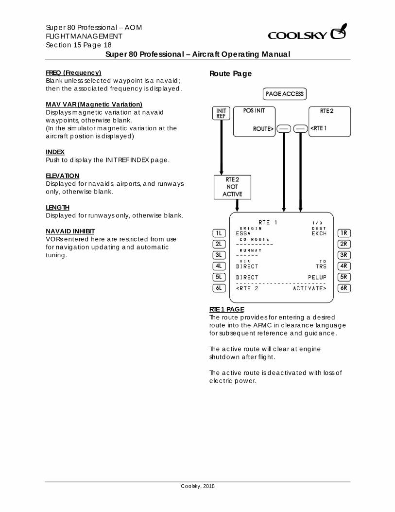
Super 80 Professional – AOM FLIGHT MANAGEMENT Section 15 Page 18
Super 80 Professional – Aircraft Operating Manual
Coolsky, 2018
FREQ (Frequency) Blank unless selected waypoint is a navaid; then the associated frequency is displayed. MAV VAR (Magnetic Variation) Displays magnetic variation at navaid waypoints, otherwise blank. (In the simulator magnetic variation at the aircraft position is displayed) INDEX Push to display the INIT REF INDEX page. ELEVATION Displayed for navaids, airports, and runways only, otherwise blank. LENGTH Displayed for runways only, otherwise blank. NAVAID INHIBIT VORs entered here are restricted from use for navigation updating and automatic tuning.
Route Page
RTE 1 PAGE The route provides for entering a desired route into the AFMC in clearance language for subsequent reference and guidance. The active route will clear at engine shutdown after flight. The active route is deactivated with loss of electric power.
Super 80 Professional – AOM FLIGHT MANAGEMENT Section 15 Page 19
Super 80 Professional – Aircraft Operating Manual
Coolsky, 2018
ORIGIN Automatically set on the RTE page if already set on POS page 1. Valid entries are four letter ICAO airport identifiers contained in the database. Entry clears previous route. Entry is inhibited in flight for active route. Entry transfers to POS page 1 if position has not yet been entered on the POS page. COMPANY ROUTE (CO ROUTE) Loads a predefined company route from the AFMC database. In the Super 80 Professional this feature is used to load P3D flight plans. For further information on how to load P3D flight plans into the FMS, please refer to the General chapter under Section 15 of this AOM. RUNWAY Valid entries are origin airport runways contained in the database. The departure runway can be entered by line selection on the DEPARTURES page or by manually typing in runway fix, e.g. 27R or RW27R. VIA Valid entries are DIRECT or airway contained in the database. Airway entries are allowed only if the waypoint on the previous line is stored in the database as a waypoint on the selected airways. Procedure names (SID, STAR, etc.) automatically appear when selected on the DEPARTURES or ARRIVALS pages.
RTE 2 Selection displays the RTE 2 page. Destination (DEST) Valid entries are four letter ICAO airport identifiers contained in the database.
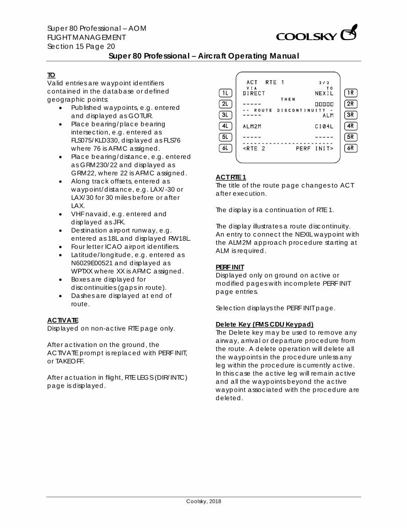
Super 80 Professional – AOM FLIGHT MANAGEMENT Section 15 Page 20
Super 80 Professional – Aircraft Operating Manual
Coolsky, 2018
TO Valid entries are waypoint identifiers contained in the database or defined geographic points:
• Published waypoints, e.g. entered and displayed as GOTUR.
• Place bearing/place bearing intersection, e.g. entered as FLS075/KLD330, displayed as FLS76 where 76 is AFMC assigned.
• Place bearing/distance, e.g. entered as GRM230/22 and displayed as GRM22, where 22 is AFMC assigned.
• Along track offsets, entered as waypoint/distance, e.g. LAX/-30 or LAX/30 for 30 miles before or after LAX.
• VHF navaid, e.g. entered and displayed as JFK.
• Destination airport runway, e.g. entered as 18L and displayed RW18L.
• Four letter ICAO airport identifiers. • Latitude/longitude, e.g. entered as
N6029E00521 and displayed as WPTXX where XX is AFMC assigned.
• Boxes are displayed for discontinuities (gaps in route).
• Dashes are displayed at end of route.
ACTIVATE Displayed on non-active RTE page only. After activation on the ground, the ACTIVATE prompt is replaced with PERF INIT, or TAKEOFF. After actuation in flight, RTE LEGS (DIR/INTC) page is displayed.
ACT RTE 1 The title of the route page changes to ACT after execution. The display is a continuation of RTE 1. The display illustrates a route discontinuity. An entry to connect the NEXIL waypoint with the ALM2M approach procedure starting at ALM is required. PERF INIT Displayed only on ground on active or modified pages with incomplete PERF INIT page entries. Selection displays the PERF INIT page. Delete Key (FMS CDU Keypad) The Delete key may be used to remove any airway, arrival or departure procedure from the route. A delete operation will delete all the waypoints in the procedure unless any leg within the procedure is currently active. In this case the active leg will remain active and all the waypoints beyond the active waypoint associated with the procedure are deleted.
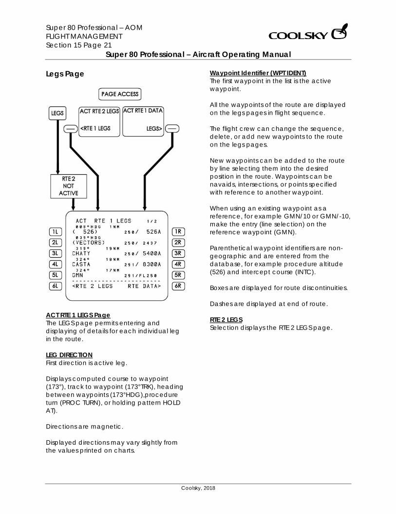
Super 80 Professional – AOM FLIGHT MANAGEMENT Section 15 Page 21
Super 80 Professional – Aircraft Operating Manual
Coolsky, 2018
Legs Page
ACT RTE 1 LEGS Page The LEGS page permits entering and displaying of details for each individual leg in the route. LEG DIRECTION First direction is active leg. Displays computed course to waypoint (173°), track to waypoint (173°TRK), heading between waypoints (173°HDG),procedure turn (PROC TURN), or holding pattern HOLD AT). Directions are magnetic. Displayed directions may vary slightly from the values printed on charts.
Waypoint Identifier (WPT IDENT) The first waypoint in the list is the active waypoint. All the waypoints of the route are displayed on the legs pages in flight sequence. The flight crew can change the sequence, delete, or add new waypoints to the route on the legs pages. New waypoints can be added to the route by line selecting them into the desired position in the route. Waypoints can be navaids, intersections, or points specified with reference to another waypoint. When using an existing waypoint as a reference, for example GMN/10 or GMN/-10, make the entry (line selection) on the reference waypoint (GMN). Parenthetical waypoint identifiers are non-geographic and are entered from the database, for example procedure altitude (526) and intercept course (INTC). Boxes are displayed for route discontinuities. Dashes are displayed at end of route. RTE 2 LEGS Selection displays the RTE 2 LEGS page.
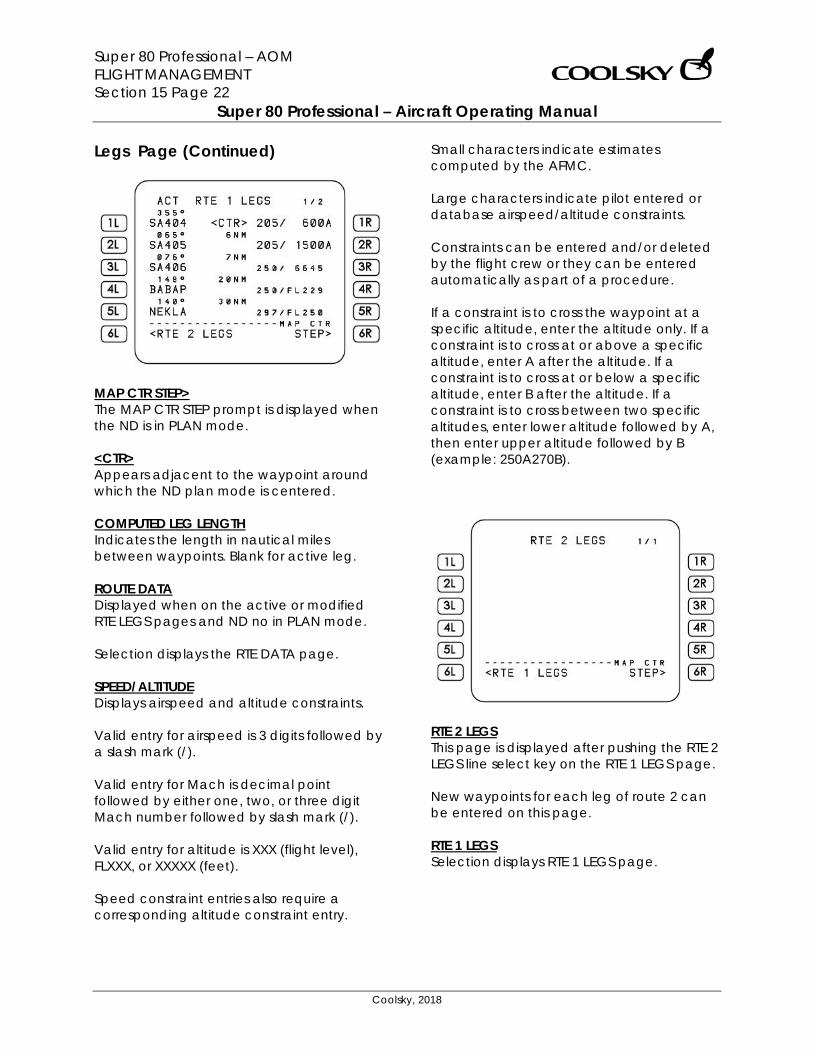
Super 80 Professional – AOM FLIGHT MANAGEMENT Section 15 Page 22
Super 80 Professional – Aircraft Operating Manual
Coolsky, 2018
Legs Page (Continued)
MAP CTR STEP> The MAP CTR STEP prompt is displayed when the ND is in PLAN mode. <CTR> Appears adjacent to the waypoint around which the ND plan mode is centered. COMPUTED LEG LENGTH Indicates the length in nautical miles between waypoints. Blank for active leg. ROUTE DATA Displayed when on the active or modified RTE LEGS pages and ND no in PLAN mode. Selection displays the RTE DATA page. SPEED/ALTITUDE Displays airspeed and altitude constraints. Valid entry for airspeed is 3 digits followed by a slash mark (/). Valid entry for Mach is decimal point followed by either one, two, or three digit Mach number followed by slash mark (/). Valid entry for altitude is XXX (flight level), FLXXX, or XXXXX (feet). Speed constraint entries also require a corresponding altitude constraint entry.
Small characters indicate estimates computed by the AFMC. Large characters indicate pilot entered or database airspeed/altitude constraints. Constraints can be entered and/or deleted by the flight crew or they can be entered automatically as part of a procedure. If a constraint is to cross the waypoint at a specific altitude, enter the altitude only. If a constraint is to cross at or above a specific altitude, enter A after the altitude. If a constraint is to cross at or below a specific altitude, enter B after the altitude. If a constraint is to cross between two specific altitudes, enter lower altitude followed by A, then enter upper altitude followed by B (example: 250A270B).
RTE 2 LEGS This page is displayed after pushing the RTE 2 LEGS line select key on the RTE 1 LEGS page. New waypoints for each leg of route 2 can be entered on this page. RTE 1 LEGS Selection displays RTE 1 LEGS page.
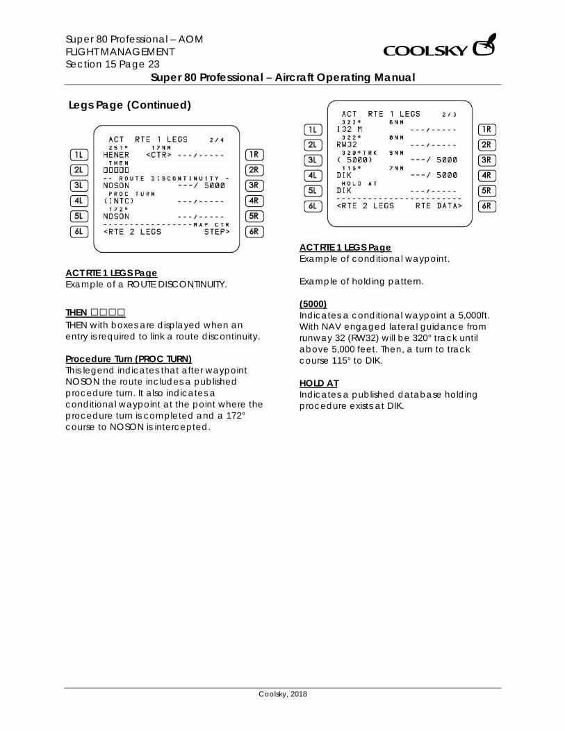
Super 80 Professional – AOM FLIGHT MANAGEMENT Section 15 Page 23
Super 80 Professional – Aircraft Operating Manual
Coolsky, 2018
Legs Page (Continued)
ACT RTE 1 LEGS Page Example of a ROUTE DISCONTINUITY.
THEN □□□□ THEN with boxes are displayed when an entry is required to link a route discontinuity. Procedure Turn (PROC TURN) This legend indicates that after waypoint NOSON the route includes a published procedure turn. It also indicates a conditional waypoint at the point where the procedure turn is completed and a 172° course to NOSON is intercepted.
ACT RTE 1 LEGS Page Example of conditional waypoint. Example of holding pattern. (5000) Indicates a conditional waypoint a 5,000ft. With NAV engaged lateral guidance from runway 32 (RW32) will be 320° track until above 5,000 feet. Then, a turn to track course 115° to DIK. HOLD AT Indicates a published database holding procedure exists at DIK.
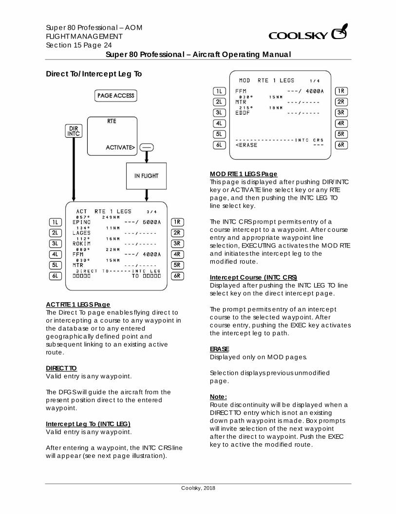
Super 80 Professional – AOM FLIGHT MANAGEMENT Section 15 Page 24
Super 80 Professional – Aircraft Operating Manual
Coolsky, 2018
Direct To/Intercept Leg To
ACT RTE 1 LEGS Page The Direct To page enables flying direct to or intercepting a course to any waypoint in the database or to any entered geographically defined point and subsequent linking to an existing active route. DIRECT TO Valid entry is any waypoint. The DFGS will guide the aircraft from the present position direct to the entered waypoint. Intercept Leg To (INTC LEG) Valid entry is any waypoint. After entering a waypoint, the INTC CRS line will appear (see next page illustration).
MOD RTE 1 LEGS Page This page is displayed after pushing DIR/INTC key or ACTIVATE line select key or any RTE page, and then pushing the INTC LEG TO line select key. The INTC CRS prompt permits entry of a course intercept to a waypoint. After course entry and appropriate waypoint line selection, EXECUTING activates the MOD RTE and initiates the intercept leg to the modified route. Intercept Course (INTC CRS) Displayed after pushing the INTC LEG TO line select key on the direct intercept page. The prompt permits entry of an intercept course to the selected waypoint. After course entry, pushing the EXEC key activates the intercept leg to path. ERASE Displayed only on MOD pages. Selection displays previous unmodified page. Note: Route discontinuity will be displayed when a DIRECT TO entry which is not an existing down path waypoint is made. Box prompts will invite selection of the next waypoint after the direct to waypoint. Push the EXEC key to active the modified route.
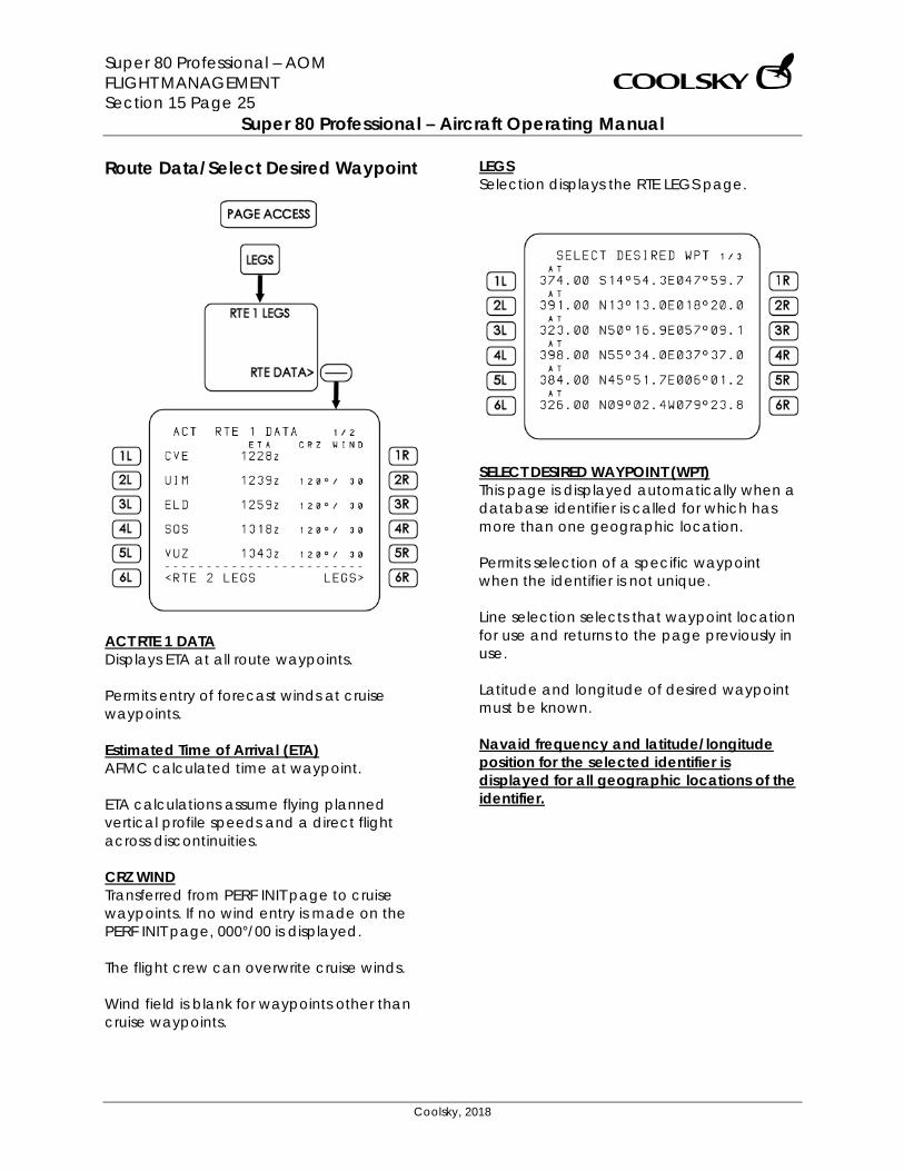
Super 80 Professional – AOM FLIGHT MANAGEMENT Section 15 Page 25
Super 80 Professional – Aircraft Operating Manual
Coolsky, 2018
Route Data/Select Desired Waypoint
ACT RTE 1 DATA Displays ETA at all route waypoints. Permits entry of forecast winds at cruise waypoints. Estimated Time of Arrival (ETA) AFMC calculated time at waypoint. ETA calculations assume flying planned vertical profile speeds and a direct flight across discontinuities. CRZ WIND Transferred from PERF INIT page to cruise waypoints. If no wind entry is made on the PERF INIT page, 000°/00 is displayed. The flight crew can overwrite cruise winds. Wind field is blank for waypoints other than cruise waypoints.
LEGS Selection displays the RTE LEGS page.
SELECT DESIRED WAYPOINT (WPT) This page is displayed automatically when a database identifier is called for which has more than one geographic location. Permits selection of a specific waypoint when the identifier is not unique. Line selection selects that waypoint location for use and returns to the page previously in use. Latitude and longitude of desired waypoint must be known. Navaid frequency and latitude/longitude position for the selected identifier is displayed for all geographic locations of the identifier.
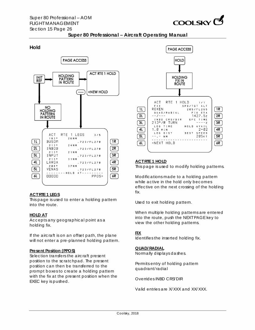
Super 80 Professional – AOM FLIGHT MANAGEMENT Section 15 Page 26
Super 80 Professional – Aircraft Operating Manual
Coolsky, 2018
Hold
ACT RTE 1 LEGS This page is used to enter a holding pattern into the route. HOLD AT Accepts any geographical point as a holding fix. If the aircraft is on an offset path, the plane will not enter a pre-planned holding pattern. Present Position (PPOS) Selection transfers the aircraft present position to the scratchpad. The present position can then be transferred to the prompt boxes to create a holding pattern with the fix at the present position when the EXEC key is pushed.
ACT RTE 1 HOLD This page is used to modify holding patterns. Modifications made to a holding pattern while active in the hold only becomes effective on the next crossing of the holding fix. Used to exit holding pattern. When multiple holding patterns are entered into the route, push the NEXT PAGE key to view the other holding patterns. FIX Identifies the inserted holding fix. QUAD/RADIAL Normally displays dashes. Permits entry of holding pattern quadrant/radial Overrides INBD CRS/DIR Valid entries are X/XXX and XX/XXX.
Super 80 Professional – AOM FLIGHT MANAGEMENT Section 15 Page 27
Super 80 Professional – Aircraft Operating Manual
Coolsky, 2018
INBD CRS/DIR Permits keyboard entry for inbound holding course and direction. Default direction is right hand patterns. Overrides QUAD/RADIAL. Valid entries are XXX (course), XXX/X and /X (turn direction). LEG TIME Displays 1.0 minutes at or below 14,000 feet and 1.5 minutes above 14,000 feet by default. Can be changed by flight crew entry. Overrides LEG DIST display. Displays dashes if LEG DIST value is entered. LEG DIST Normally displays dashes. Value can be entered by the flight crew or by stored procedure. Overrides LEG TIME display when selected. NEXT HOLD Selection creates prompts for entering a new holding fix. Speed/Target Altitude (SPD/TGT ALT) Displays target speed and altitude. If not specified, dashes are displayed. Entry of a TGT ALT higher than the waypoint altitude results in a climb after entering holding. Entry of a TGT ALT lower than the waypoint altitude results in a cruise descent after entering holding. Valid entries are combinations of SPD/TGT ALT; XXX/ (for speed), XXX, XXXX or XXXXX (for altitude).
FIX ETA Displays the next time the holding fix will be passed. EFC TIME Displays crew entered Expect Further Clearance time. Hold Available (HOLD AVAIL) Displays available holding time before exit is required to reach destination with RESERVES as entered into the PERF INIT page. BEST SPEED Displays the best holding speed for the current altitude and conditions. EXIT HOLD Selection causes EXIT ARMED to appear. EXIT ARMED Displayed after pushing the EXIT HOLD line select key. Pushing EXEC key results in flight directly back to the fix and along the active route.
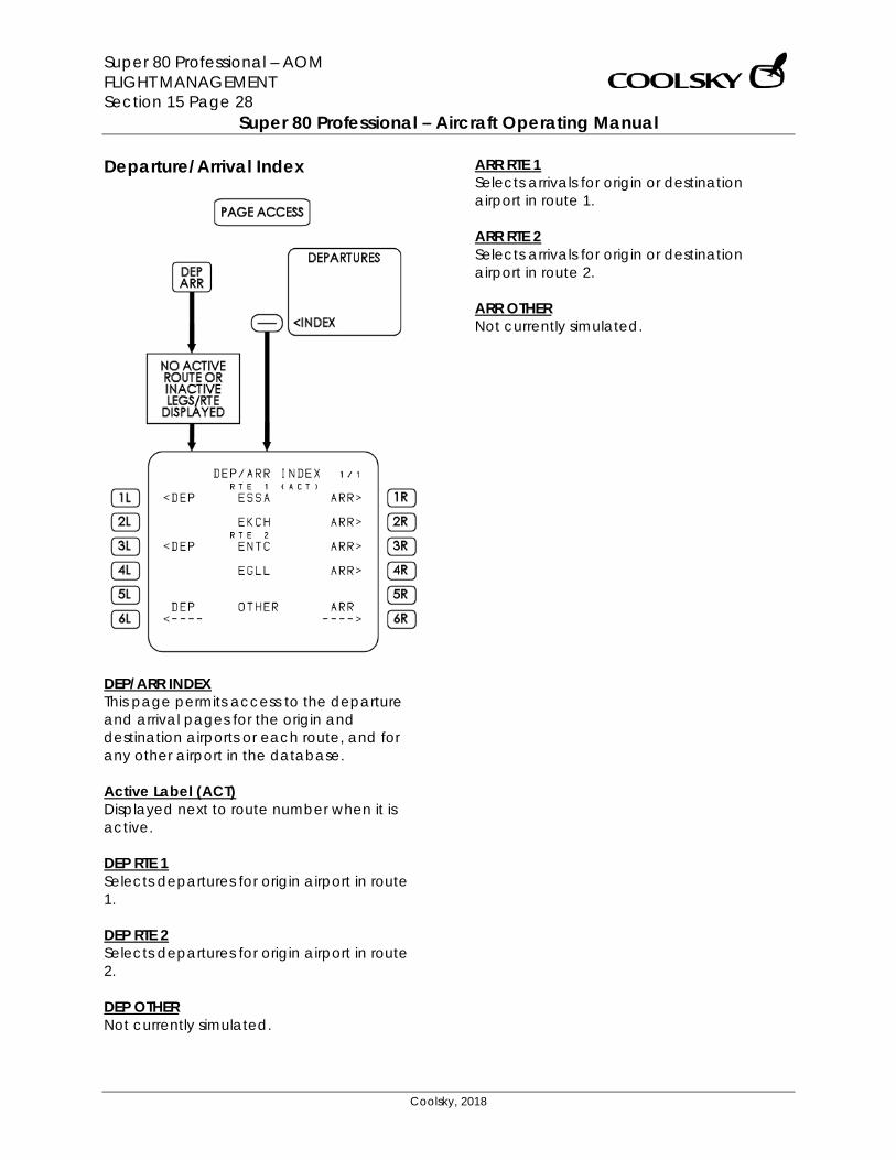
Super 80 Professional – AOM FLIGHT MANAGEMENT Section 15 Page 28
Super 80 Professional – Aircraft Operating Manual
Coolsky, 2018
Departure/Arrival Index
DEP/ARR INDEX This page permits access to the departure and arrival pages for the origin and destination airports or each route, and for any other airport in the database. Active Label (ACT) Displayed next to route number when it is active. DEP RTE 1 Selects departures for origin airport in route 1. DEP RTE 2 Selects departures for origin airport in route 2. DEP OTHER Not currently simulated.
ARR RTE 1 Selects arrivals for origin or destination airport in route 1. ARR RTE 2 Selects arrivals for origin or destination airport in route 2. ARR OTHER Not currently simulated.
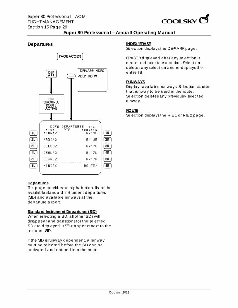
Super 80 Professional – AOM FLIGHT MANAGEMENT Section 15 Page 29
Super 80 Professional – Aircraft Operating Manual
Coolsky, 2018
Departures
Departures This page provides an alphabetical list of the available standard instrument departures (SID) and available runways at the departure airport. Standard Instrument Departures (SID) When selecting a SID, all other SIDs will disappear and transitions for the selected SID are displayed. <SEL> appears next to the selected SID. If the SID is runway dependent, a runway must be selected before the SID can be activated and entered into the route.
INDEX/ERASE Selection displays the DEP/ARR page. ERASE is displayed after any selection is made and prior to execution. Selection deletes any selection and re-displays the entire list. RUNWAYS Displays available runways. Selection causes that runway to be used in the route. Selection deletes any previously selected runway. ROUTE Selection displays the RTE 1 or RTE 2 page.
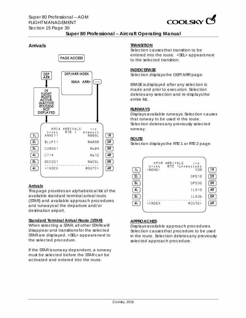
Super 80 Professional – AOM FLIGHT MANAGEMENT Section 15 Page 30
Super 80 Professional – Aircraft Operating Manual
Coolsky, 2018
Arrivals
Arrivals This page provides an alphabetical list of the available standard terminal arrival routs (STAR) and available approach procedures and runways at the departure and/or destination airport. Standard Terminal Arrival Route (STAR) When selecting a STAR, all other STARs will disappear and transitions for the selected STAR are displayed. <SEL> appears next to the selected procedure. If the STAR is runway dependent, a runway must be selected before the STAR can be activated and entered into the route.
TRANSITION Selection causes that transition to be entered into the route. <SEL> appears next to the selected transition. INDEX/ERASE Selection displays the DEP/ARR page. ERASE is displayed after any selection is made and prior to execution. Selection deletes any selection and re-displays the entire list. RUNWAYS Displays available runways. Selection causes that runway to be used in the route. Selection deletes any previously selected runway. ROUTE Selection displays the RTE 1 or RTE 2 page.
APPROACHES Displays available approach procedures. Selection causes that procedure to be used in the route. Selection deletes any previously selected approach procedure.
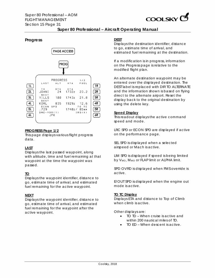
Super 80 Professional – AOM FLIGHT MANAGEMENT Section 15 Page 31
Super 80 Professional – Aircraft Operating Manual
Coolsky, 2018
Progress
PROGRESS Page 1/2 This page displays various flight progress data. LAST Displays the last passed waypoint, along with altitude, time and fuel remaining at that waypoint at the time the waypoint was passed. TO Displays the waypoint identifier, distance to go, estimate time of arrival, and estimated fuel remaining for the active waypoint. NEXT Displays the waypoint identifier, distance to go, estimate time of arrival, and estimated fuel remaining for the waypoint after the active waypoint.
DEST Displays the destination identifier, distance to go, estimate time of arrival, and estimated fuel remaining at the destination. If a modification is in progress, information on the Progress page is relative to the modified flight plan. An alternate destination waypoint may be entered over the displayed destination. The DEST label is replaced with DIR TO ALTERNATE and the information shown is based on flying direct to the alternate airport. Reset the display back to the original destination by using the delete key. Speed Display This readout displays the active command speed and mode. LRC SPD or ECON SPD are displayed if active on the performance page. SEL SPD is displayed when a selected airspeed or Mach is active. LIM SPD is displayed if speed is being limited by VMO, MMO or FLAP limit or ALPHA limit. SPD OVRD is displayed when FMS override is active. E/OUT SPD is displayed when the engine out mode is active. TO TC Display Displays ETA and distance to Top of Climb when climb is active. Other displays are:
• TO TD – When cruise is active and within 200 nautical miles of TD.
• TO ED – When descent is active.
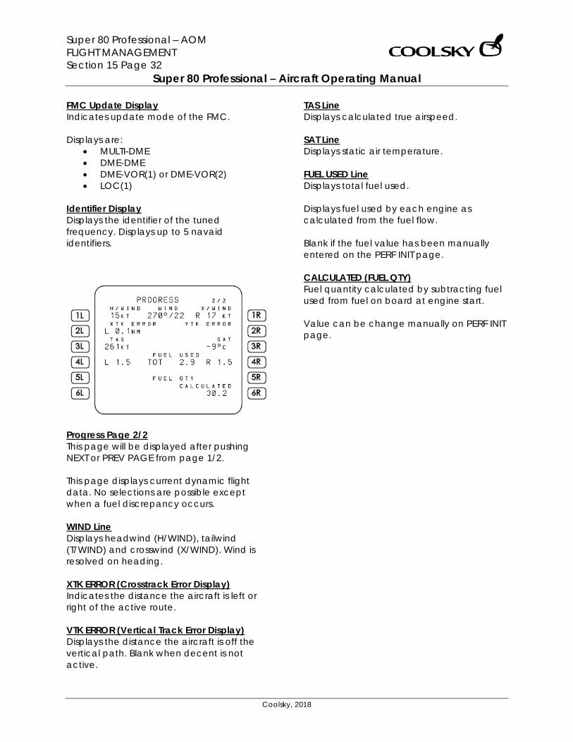
Super 80 Professional – AOM FLIGHT MANAGEMENT Section 15 Page 32
Super 80 Professional – Aircraft Operating Manual
Coolsky, 2018
FMC Update Display Indicates update mode of the FMC. Displays are:
• MULTI-DME • DME-DME • DME-VOR(1) or DME-VOR(2) • LOC(1)
Identifier Display Displays the identifier of the tuned frequency. Displays up to 5 navaid identifiers.
Progress Page 2/2 This page will be displayed after pushing NEXT or PREV PAGE from page 1/2. This page displays current dynamic flight data. No selections are possible except when a fuel discrepancy occurs. WIND Line Displays headwind (H/WIND), tailwind (T/WIND) and crosswind (X/WIND). Wind is resolved on heading. XTK ERROR (Crosstrack Error Display) Indicates the distance the aircraft is left or right of the active route. VTK ERROR (Vertical Track Error Display) Displays the distance the aircraft is off the vertical path. Blank when decent is not active.
TAS Line Displays calculated true airspeed. SAT Line Displays static air temperature. FUEL USED Line Displays total fuel used. Displays fuel used by each engine as calculated from the fuel flow. Blank if the fuel value has been manually entered on the PERF INIT page. CALCULATED (FUEL QTY) Fuel quantity calculated by subtracting fuel used from fuel on board at engine start. Value can be change manually on PERF INIT page.
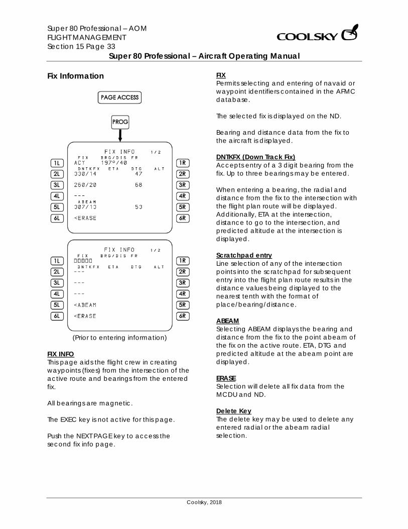
Super 80 Professional – AOM FLIGHT MANAGEMENT Section 15 Page 33
Super 80 Professional – Aircraft Operating Manual
Coolsky, 2018
Fix Information
(Prior to entering information)
FIX INFO This page aids the flight crew in creating waypoints (fixes) from the intersection of the active route and bearings from the entered fix. All bearings are magnetic. The EXEC key is not active for this page. Push the NEXT PAGE key to access the second fix info page.
FIX Permits selecting and entering of navaid or waypoint identifiers contained in the AFMC database. The selected fix is displayed on the ND. Bearing and distance data from the fix to the aircraft is displayed. DNTKFX (Down Track Fix) Accepts entry of a 3 digit bearing from the fix. Up to three bearings may be entered. When entering a bearing, the radial and distance from the fix to the intersection with the flight plan route will be displayed. Additionally, ETA at the intersection, distance to go to the intersection, and predicted altitude at the intersection is displayed. Scratchpad entry Line selection of any of the intersection points into the scratchpad for subsequent entry into the flight plan route results in the distance values being displayed to the nearest tenth with the format of place/bearing/distance. ABEAM Selecting ABEAM displays the bearing and distance from the fix to the point abeam of the fix on the active route. ETA, DTG and predicted altitude at the abeam point are displayed. ERASE Selection will delete all fix data from the MCDU and ND. Delete Key The delete key may be used to delete any entered radial or the abeam radial selection.
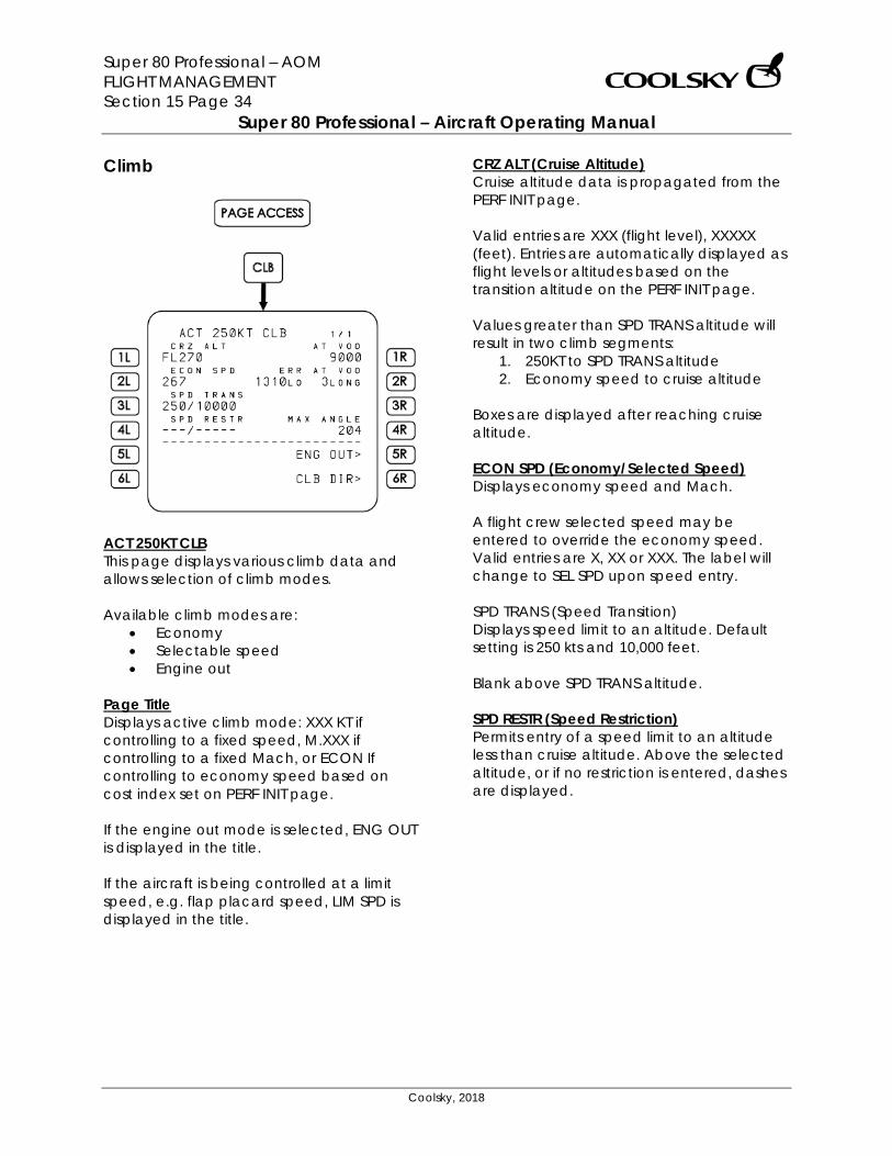
Super 80 Professional – AOM FLIGHT MANAGEMENT Section 15 Page 34
Super 80 Professional – Aircraft Operating Manual
Coolsky, 2018
Climb
ACT 250KT CLB This page displays various climb data and allows selection of climb modes. Available climb modes are:
• Economy • Selectable speed • Engine out
Page Title Displays active climb mode: XXX KT if controlling to a fixed speed, M.XXX if controlling to a fixed Mach, or ECON If controlling to economy speed based on cost index set on PERF INIT page. If the engine out mode is selected, ENG OUT is displayed in the title. If the aircraft is being controlled at a limit speed, e.g. flap placard speed, LIM SPD is displayed in the title.
CRZ ALT (Cruise Altitude) Cruise altitude data is propagated from the PERF INIT page. Valid entries are XXX (flight level), XXXXX (feet). Entries are automatically displayed as flight levels or altitudes based on the transition altitude on the PERF INIT page. Values greater than SPD TRANS altitude will result in two climb segments:
1. 250KT to SPD TRANS altitude 2. Economy speed to cruise altitude
Boxes are displayed after reaching cruise altitude. ECON SPD (Economy/Selected Speed) Displays economy speed and Mach. A flight crew selected speed may be entered to override the economy speed. Valid entries are X, XX or XXX. The label will change to SEL SPD upon speed entry. SPD TRANS (Speed Transition) Displays speed limit to an altitude. Default setting is 250 kts and 10,000 feet. Blank above SPD TRANS altitude. SPD RESTR (Speed Restriction) Permits entry of a speed limit to an altitude less than cruise altitude. Above the selected altitude, or if no restriction is entered, dashes are displayed.
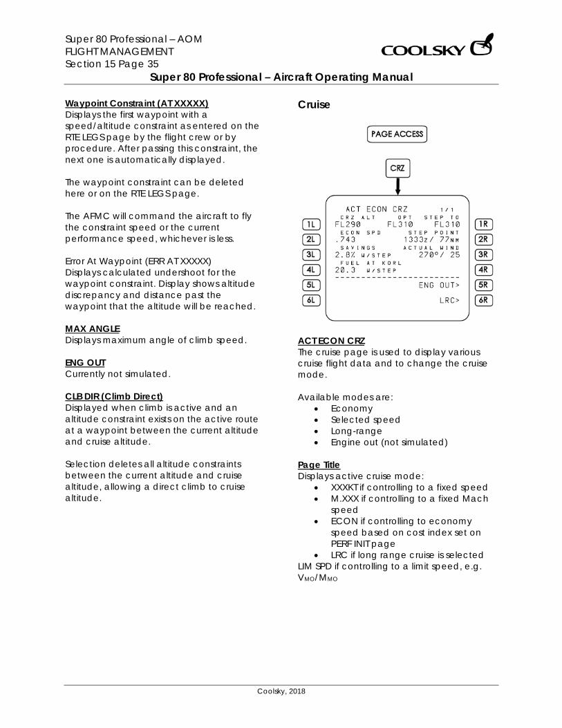
Super 80 Professional – AOM FLIGHT MANAGEMENT Section 15 Page 35
Super 80 Professional – Aircraft Operating Manual
Coolsky, 2018
Waypoint Constraint (AT XXXXX) Displays the first waypoint with a speed/altitude constraint as entered on the RTE LEGS page by the flight crew or by procedure. After passing this constraint, the next one is automatically displayed. The waypoint constraint can be deleted here or on the RTE LEGS page. The AFMC will command the aircraft to fly the constraint speed or the current performance speed, whichever is less. Error At Waypoint (ERR AT XXXXX) Displays calculated undershoot for the waypoint constraint. Display shows altitude discrepancy and distance past the waypoint that the altitude will be reached. MAX ANGLE Displays maximum angle of climb speed. ENG OUT Currently not simulated. CLB DIR (Climb Direct) Displayed when climb is active and an altitude constraint exists on the active route at a waypoint between the current altitude and cruise altitude. Selection deletes all altitude constraints between the current altitude and cruise altitude, allowing a direct climb to cruise altitude.
Cruise
ACT ECON CRZ The cruise page is used to display various cruise flight data and to change the cruise mode. Available modes are:
• Economy • Selected speed • Long-range • Engine out (not simulated)
Page Title Displays active cruise mode:
• XXXKT if controlling to a fixed speed • M.XXX if controlling to a fixed Mach
speed • ECON if controlling to economy
speed based on cost index set on PERF INIT page
• LRC if long range cruise is selected LIM SPD if controlling to a limit speed, e.g. VMO/MMO
Super 80 Professional – AOM FLIGHT MANAGEMENT Section 15 Page 36
Super 80 Professional – Aircraft Operating Manual
Coolsky, 2018
CRZ ALT (Cruise altitude) Displays the selected cruise altitude for the route as set on the PERF INIT page. Valid entries are XXX (flight level), FLXXX or XXXXX (feet). The cruise altitude is automatically displayed as flight level or altitude based on the transition altitude as set on the PERF INIT page. The cruise altitude is forwarded to all pages displaying cruise altitude information. Changing the cruise altitude will cause the page title to change to CRZ CLB og CRZ DES. SPD (Speed) Displays active command speed or Mach. The label can show ECON, LRC, SEL or EOUT SPD (not simulated). A selected speed set by the flight crew will be forwarded to the descent page provided a descent constraint is present. SAVINGS Displays AFMC predicted fuel savings or penalty associated with flying the step climb or descent as displayed. Calculations are based on making the step from the STEP POINT or, when past the STEP POINT, from the present position. Label will display PENALTY when appropriate. The SAVINGS or PENALTY readout will be suffixed by W/MOD if a flight plan modification is pending. Blank if no step altitude is displayed.
FUEL AT XXXX (Fuel at Destination) Displays the AFMC predicted fuel remaining upon reaching the destination. If step information is displayed, the fuel display assumes the step will occur and the fuel display is suffixed by W/STEP. Calculations are based on making the step from the STEP POINT or, when past the STEP POINT, from the present position. The fuel display readout will be suffixed by W/MOD if a flight plan modification is pending. OPT (Optimum Altitude) Displays the optimum altitude to fly at based on aircraft gross weight, cost index and trip length. STEP TO (Step to Altitude) Automatically displays 2000 feet higher than cruise altitude. The step altitude may be overwritten by the flight crew. Any new value remains until a new CRZ ALT has been entered. Valid entries are XXX (flight level), FLXXX or XXXXX (feet). Blank when there is no active flight plan, or when within 200 NM of TD (Top of Descent). STEP POINT Displays ETA and distance to go to the optimum step point if the aircraft is more than 200 NM from TD. The label changes to TD when within 200 NM of TD. ETA and distance displayed are then relative to TD.
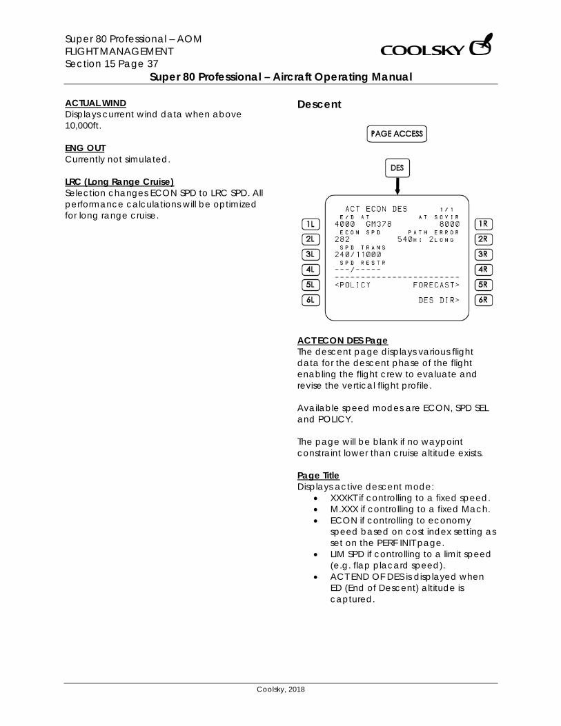
Super 80 Professional – AOM FLIGHT MANAGEMENT Section 15 Page 37
Super 80 Professional – Aircraft Operating Manual
Coolsky, 2018
ACTUAL WIND Displays current wind data when above 10,000ft. ENG OUT Currently not simulated. LRC (Long Range Cruise) Selection changes ECON SPD to LRC SPD. All performance calculations will be optimized for long range cruise.
Descent
ACT ECON DES Page The descent page displays various flight data for the descent phase of the flight enabling the flight crew to evaluate and revise the vertical flight profile. Available speed modes are ECON, SPD SEL and POLICY. The page will be blank if no waypoint constraint lower than cruise altitude exists. Page Title Displays active descent mode:
• XXXKT if controlling to a fixed speed. • M.XXX if controlling to a fixed Mach. • ECON if controlling to economy
speed based on cost index setting as set on the PERF INIT page.
• LIM SPD if controlling to a limit speed (e.g. flap placard speed).
• ACT END OF DES is displayed when ED (End of Descent) altitude is captured.
Super 80 Professional – AOM FLIGHT MANAGEMENT Section 15 Page 38
Super 80 Professional – Aircraft Operating Manual
Coolsky, 2018
ED AT (End of Descent at) Displays the last/lowest waypoint constraint on the route. Data is transferred from the LEGS page. SPEED Displays command speed or Mach. Label can display ECON SPD, SEL SPD or POLICY SPD. The flight crew may enter SEL SPD (Mach or speed). Valid entries are .X, .XX or .XXX for Mach, and XXX for airspeed. When the speed label indicates SEL SPD or POLICY SPD, an ECON prompt will be displayed on the page. The speed display will automatically change from Mach to speed upon transitioning through FL270 when flying in ECON SPD mode. SPD TRANS (Speed Transition) The descent speed transition is by default set to 240kts below 10,000 feet. Below SPD TRANS altitude, the display is blank. SPD RESTR (Speed Restriction) The flight crew can manually set a speed limit at an altitude higher than the ED altitude. When the aircraft transitions below the set restriction altitude, the display will be dashed out. Waypoint Constraint (AT SOVIR) The first waypoint speed/altitude constraint on the active route is displayed here when constraints have been entered on a RTE LEGS page procedure or by crew entry. When passing the waypoint constraint, then next one, if there is one, is automatically displayed.
The waypoint constraint can be deleted on this page or on the RTE LEGS page. The target speed commanded by the AFMC is the lowest of the constraint speed or the current performance speed. PATH ERROR Indicates how much the aircraft is deviating from the AFMC calculated descent profile and how much long or short of the target ED point the aircraft will reach the target altitude. Displayed when the descent mode is active. Blank if no descent deviation is predicted. FORECAST Selection opens the Descent Forecasts page. DES NOW (6R) Selection and execution starts an immediate descent towards the first constrained waypoint. DES DIR (6R) Is displayed when descent is active and a waypoint constraint exits between the current position and the ED waypoint. Selection deletes all waypoint constraints between the current position and the ED waypoint. Descent Mode (5L) Displays ECON when the active descent mode is not economy. Displays POLICY when the active descent mode is economy.
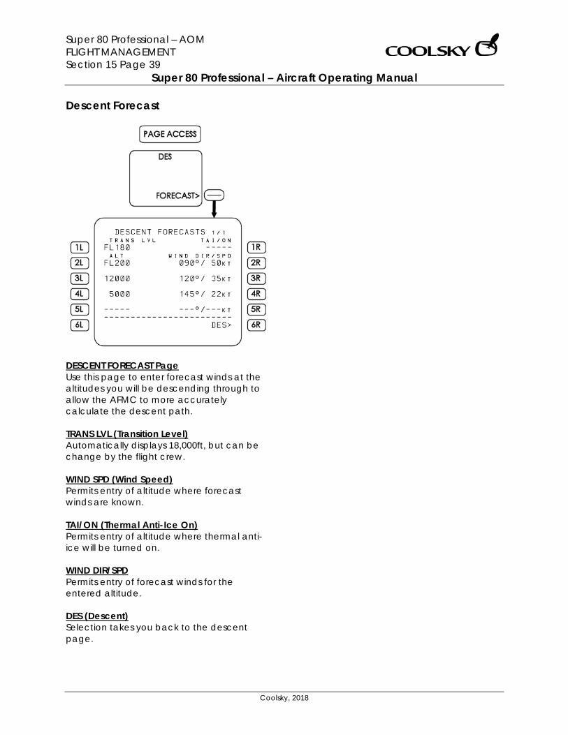
Super 80 Professional – AOM FLIGHT MANAGEMENT Section 15 Page 39
Super 80 Professional – Aircraft Operating Manual
Coolsky, 2018
Descent Forecast
DESCENT FORECAST Page Use this page to enter forecast winds at the altitudes you will be descending through to allow the AFMC to more accurately calculate the descent path. TRANS LVL (Transition Level) Automatically displays 18,000ft, but can be change by the flight crew. WIND SPD (Wind Speed) Permits entry of altitude where forecast winds are known. TAI/ON (Thermal Anti-Ice On) Permits entry of altitude where thermal anti-ice will be turned on. WIND DIR/SPD Permits entry of forecast winds for the entered altitude. DES (Descent) Selection takes you back to the descent page.
Super 80 Professional – AOM FLIGHT MANAGEMENT Section 15 Page 40
Super 80 Professional – Aircraft Operating Manual
Coolsky, 2018
FMS OPERATIONS
IRS Operation Initial alignment
• Set both IRS Mode Select switches to NAV.
• Observe ON BAT annunciations illuminate during self-test, extinguish, and then the ALIGN annunciations will illuminate.
• Select the FMS POS/INIT page.
• Enter present position.
• Note: the aircraft must remain stationary during alignment. The ALIGN lights must be extinguished prior to moving the aircraft.
Shutdown
• Set both IRS Mode Select switches to OFF.
Super 80 Professional – AOM FLIGHT MANAGEMENT Section 15 Page 41
Super 80 Professional – Aircraft Operating Manual
Coolsky, 2018
FMS Initialization Configuration identification
• On power on the first page displayed on the FMS is the IDENT page.
• Check and verify: o Model number. o Engine types. o Navigation data active date. If not current, do an update.
Position Initialization
• Select the POS INIT page. • Enter a reference airport. • Use the reference airport position, or key in present position into the SET IRS POSITION field. • Note: Make sure the IRS Mode Select switches are set to NAV. • Check and verify:
o Correct position displayed on LAST POS line. o Correct GMT displayed.
Route Initialization
• Select the RTE page (RTE key).
• Clear previous route: o Enter a new origin or re-enter the previous origin to clear the route.
• Enter a destination airport.
• Enter runway and route information:
o If runway and/or SID is not known, this data may be entered later.
o To enter a runway and/or SID: Select departure page. Select the appropriate runway and/or SID.
o To enter an airway:
Enter first waypoint of the desired airway segment into TO field. Enter airway identifier into the VIA field. Enter last waypoint of the desired airway segment into TO field.
o To enter a waypoint identifier or defined geographic point into the route:
Enter the name/identification/position into the TO field. Note: Multiple navaids may share the same name. Select the appropriate
navaid on the SELECT DESIRED WPT page.
o To enter route termination: Enter the destination ident as the last waypoint of the route.
Super 80 Professional – AOM FLIGHT MANAGEMENT Section 15 Page 42
Super 80 Professional – Aircraft Operating Manual
Coolsky, 2018
Performance Initialization • Select PERF INIT page (INIT REF key).
• Enter actual fuel quantity loaded.
• Enter Zero Fuel Weight.
• Enter fuel reserves (fuel left at destination plus alternate fuel).
• Enter cost index:
o Speed is controlled by the AFMC according to the set cost index. o A zero cost index yields minimum fuel burn, low speed. o A 999 cost index yields minimum flight time, high fuel burn, high speed.
• Enter flight plan cruise altitude.
• Enter forecast winds at the cruise altitude (optional).
• Enter ISA deviation at the cruise altitude (optional).
• Select TAKEOFF REF page.
• Enter V-speed (optional).
• Verify that pre-flight initialization is complete:
o PRE-FLIGHT STATUS or COMPLETE will be displayed. Soft keys will indicate which page(s) need attention.
Super 80 Professional – AOM FLIGHT MANAGEMENT Section 15 Page 43
Super 80 Professional – Aircraft Operating Manual
Coolsky, 2018
FMS Lateral Navigation Direct to waypoint (1)
• Select the LEGS page (LEGS key).
• Line select, using the softkeys, the waypoint you wish to proceed directly to. This will be placed into the scratchpad.
• Line select the waypoint in the scratchpad back to the top of the route.
• Review the modified route on the ND.
• Execute the modified route.
Direct to waypoint (2) • Select the DIRECT TO page for the active route (DIR INTC key).
• Enter the desired waypoint ident into the DIRECT TO boxes.
• Review the modified route on the ND.
• Execute the modified route.
Intercepting a leg to a waypoint
• Select the DIRECT TO page for the active route (DIR INTC key).
• Enter the first waypoint on the leg to be intercepted into the INTC LEG boxes.
• If required, enter the leg’s inbound course into the INTC CRS boxes.
• Review the modified route on the ND.
• Execute the modified route.
• Tip: To establish the appropriate intercept track, use the HDG SEL mode and ND map display for guidance. When close to the desired leg, continue flight on NAV mode.
• Note: The real FMS will issue a warning if the aircraft is not on an intercepting course to the selected leg. This is currently not simulated.
Super 80 Professional – AOM FLIGHT MANAGEMENT Section 15 Page 44
Super 80 Professional – Aircraft Operating Manual
Coolsky, 2018
Intercepting an airway • Select the DIRECT TO page for the active route (DIR INTC key).
• Enter the desired waypoint on the airway to be intercepted into the INTC LEG boxes.
• Execute the modified route.
• Select the RTE page.
• Enter the airway identifier into the dashes on the left side of the route page.
• Enter the airway end point into the boxes on the right side of the RTE page.
• Execute the modified route.
• Select the DIRECT TO page for the active route (DIR INTC key).
• Enter the first waypoint on the airway leg to be intercepted into the INTC LEG boxes.
• Execute the modified route.
Route discontinuity/modification
• Select the LEGS or RTE page (RTE or LEGS key).
• Line select the waypoint prior to or after the discontinuity and insert that waypoint into the boxes at the discontinuity.
• Review the modified route on the ND.
• Execute the modified route. Deleting waypoints
• Select the LEGS page (LEGS key).
• Remove waypoints using the DELETE key. Press the DELETE key, then line select the waypoint to be deleted.
• Link any route discontinuities.
• Review the modified route on the ND.
• Execute the modified route.
Super 80 Professional – AOM FLIGHT MANAGEMENT Section 15 Page 45
Super 80 Professional – Aircraft Operating Manual
Coolsky, 2018
Deleting a block of waypoints • Select the LEGS page (LEGS key).
• Line select, using the softkeys, the waypoint immediately following the last waypoint to be
deleted. This will be placed into the scratchpad.
• Line select the waypoint in the scratchpad to the first waypoint of the block of waypoints to be deleted.
• Review the modified route on the ND.
• Execute the modified route.
Entering a crossing radial from a fix as a waypoint • Select the FIX page (FIX key).
• Enter the desired fix identifier.
• Enter the desired radial from the fix on the DNTKFX (downtrack fix) line, or press the
ABEAM prompt if the desired radial should be perpendicular to the route course.
• Line select the DNTKFX or ABM line to the scratchpad.
• Select the LEGS page, or the DIR INTC page if the fix is prior to the active waypoint.
• Line select the fix/radial/distance to the desired position in the route.
• Link any route discontinuities.
• Review the modified route on the ND.
• Execute the modified route.
Entering an along track speed/altitude crossing waypoint • Select the LEGS page (LEGS key).
• Line select the reference waypoint to the scratchpad.
• Enter a slash (/) then a minus sign (-) if before the reference waypoint, followed by
distance. E.g. LAX/-10 or ORL/22.
• Line select the scratchpad entry to the reference waypoint.
• Enter desired speed/altitude for crossing waypoint.
• Execute the modified route.
Super 80 Professional – AOM FLIGHT MANAGEMENT Section 15 Page 46
Super 80 Professional – Aircraft Operating Manual
Coolsky, 2018
Entering a waypoint not in the database • Select the LEGS, DIR INTC or RTE page.
• Construct the waypoint by specifying:
o Latitude and longitude. o Waypoint – radial – distance o VOR radial – VOR radial crossing.
• Line select constructed waypoint to the desired position in the route.
• Link any route discontinuities.
• Review the modified route on the ND.
• Execute the modified route.
Contingency route
• Select the RTE page (RTE key).
• Line select RTE 2.
• Enter desired route information.
• Review route 2 on the ND.
• Activate route 2 when desired.
• Select DIR INTC page (DIR INTC key).
• Link the aircraft present position with the new route by selecting direct to the first waypoint of the new route.
• Execute the new route.
Destination change • Select the RTE page (RTE key).
• Enter new destination on DEST line.
• Modify the route as necessary using the RTE or LEGS page.
• Review the modified route on the ND.
• Execute the modified route.
Super 80 Professional – AOM FLIGHT MANAGEMENT Section 15 Page 47
Super 80 Professional – Aircraft Operating Manual
Coolsky, 2018
Offset • Currently not simulated.
Navaid inhibit
• Select NAV DATA page.
• Enter navaid identifier to be inhibited into the inhibit prompt. o Two navaids can be entered. o Overwrite or DELETE clears previous entry.
Holding
• Select the HOLD page (HOLD key).
• If this is the first hold to be entered into the route, the HOLD AT prompt will appear. If there is already a hold present in the route, the hold data for the first hold in the route will be displayed. Line select NEXT HOLD to enter another hold into the route.
• Enter the desired holding fix. o If holding at the present position, line select PPOS to scratchpad and then transfer
to prompt boxes. o If holding at a waypoint, enter waypoint into scratchpad or line select from the
route, and then transfer into the prompt boxes.
• Review the modified route on the ND.
• Execute the modified route
Exit holding • Select the HOLD page (HOLD key).
• Line select EXIT HOLD.
• Verify EXIT HOLD prompt changes to EXIT ARMED.
• Execute the modified route.
Super 80 Professional – AOM FLIGHT MANAGEMENT Section 15 Page 48
Super 80 Professional – Aircraft Operating Manual
Coolsky, 2018
FMS Vertical Navigation
Temporary speed restriction • Press FMS OVRD.
• Use the SPD/MACH button to set the desired speed.
• Press FMS OVRD again to deselect override mode and resume FMS target speed.
• If speed change becomes permanent:
o Make speed change on the appropriate FMS page (CLB, CRZ, DES). Temporary altitude restriction
• Set the temporary level off altitude on the Flight Guidance Control Panel.
• Observe VNAV CAP and then VNAV LVL on the FMA when the altitude is reached. Resuming climb/descent from temporary altitude
• Set the new altitude on the Flight Guidance Control Panel.
• Press the VNAV button. Setting a speed/altitude constraint at a waypoint
• Select the LEGS page (LEGS key).
• Enter speed/altitude and line select it into the desired waypoint on the right side of the page.
o If the constraint is to cross the waypoint at a specific altitude Enter the altitude only
o If the constraint is to cross at or above an altitude Enter A after altitude
o If the constraint is to cross between two altitudes Enter lower altitude followed by A, then enter upper altitude followed by B.
• Execute the modified route.
• To delete the waypoint constraint:
o Use the DELETE key and line select to desired line. Observe AFMC computed values appear.
o Execute the modified route.
Setting a speed/altitude transition and restriction • Select the CLB or DES page.
• Enter desired speed/altitude.
• Execute the modified route.
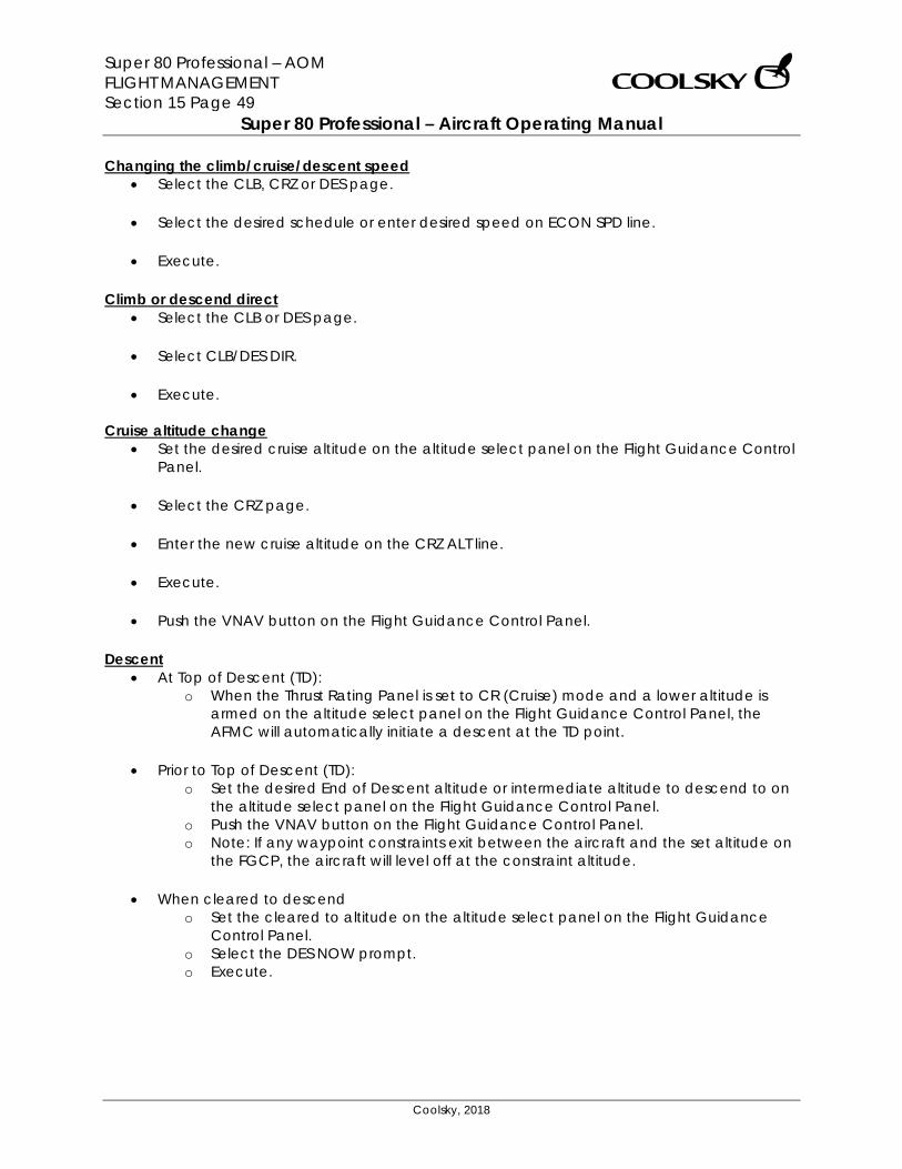
Super 80 Professional – AOM FLIGHT MANAGEMENT Section 15 Page 49
Super 80 Professional – Aircraft Operating Manual
Coolsky, 2018
Changing the climb/cruise/descent speed • Select the CLB, CRZ or DES page.
• Select the desired schedule or enter desired speed on ECON SPD line.
• Execute.
Climb or descend direct
• Select the CLB or DES page.
• Select CLB/DES DIR.
• Execute. Cruise altitude change
• Set the desired cruise altitude on the altitude select panel on the Flight Guidance Control Panel.
• Select the CRZ page.
• Enter the new cruise altitude on the CRZ ALT line.
• Execute.
• Push the VNAV button on the Flight Guidance Control Panel.
Descent • At Top of Descent (TD):
o When the Thrust Rating Panel is set to CR (Cruise) mode and a lower altitude is armed on the altitude select panel on the Flight Guidance Control Panel, the AFMC will automatically initiate a descent at the TD point.
• Prior to Top of Descent (TD):
o Set the desired End of Descent altitude or intermediate altitude to descend to on the altitude select panel on the Flight Guidance Control Panel.
o Push the VNAV button on the Flight Guidance Control Panel. o Note: If any waypoint constraints exit between the aircraft and the set altitude on
the FGCP, the aircraft will level off at the constraint altitude.
• When cleared to descend o Set the cleared to altitude on the altitude select panel on the Flight Guidance
Control Panel. o Select the DES NOW prompt. o Execute.
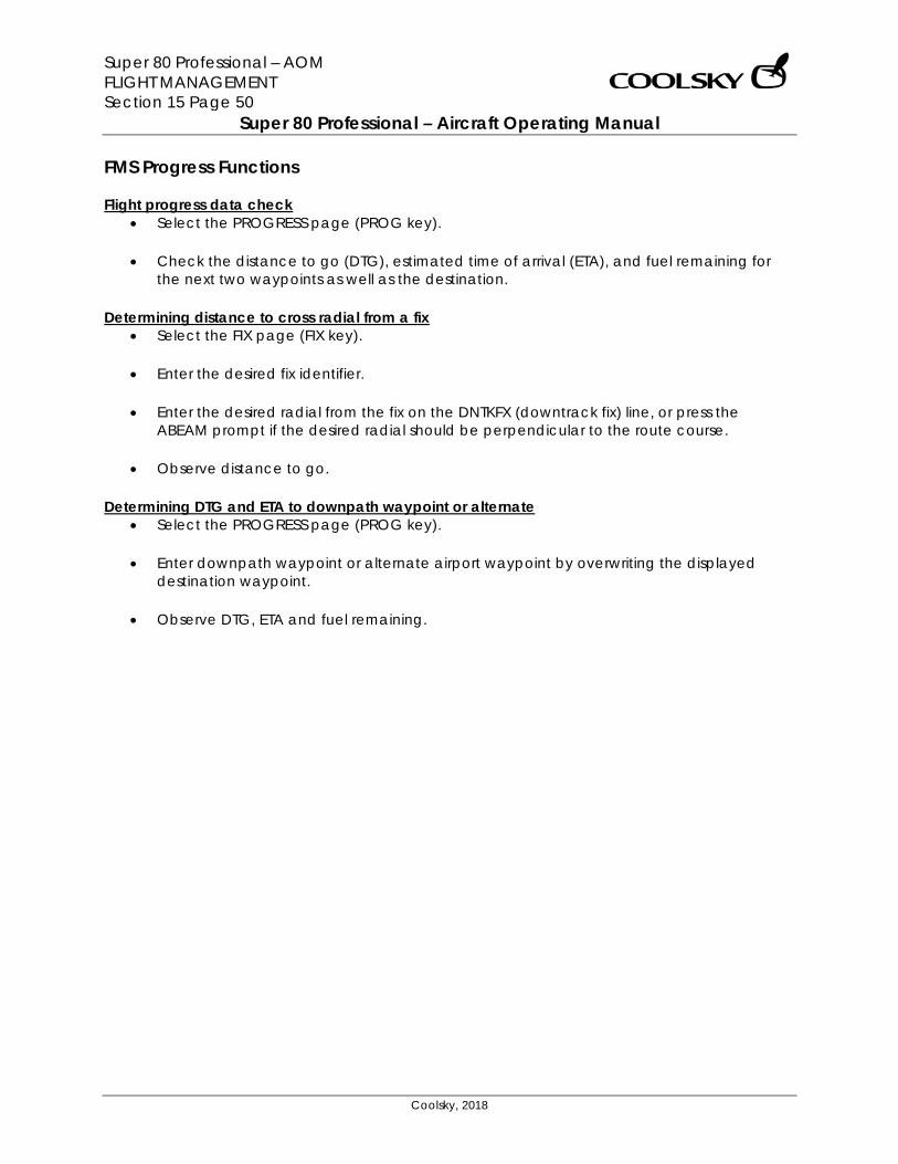
Super 80 Professional – AOM FLIGHT MANAGEMENT Section 15 Page 50
Super 80 Professional – Aircraft Operating Manual
Coolsky, 2018
FMS Progress Functions Flight progress data check
• Select the PROGRESS page (PROG key).
• Check the distance to go (DTG), estimated time of arrival (ETA), and fuel remaining for the next two waypoints as well as the destination.
Determining distance to cross radial from a fix • Select the FIX page (FIX key).
• Enter the desired fix identifier.
• Enter the desired radial from the fix on the DNTKFX (downtrack fix) line, or press the
ABEAM prompt if the desired radial should be perpendicular to the route course.
• Observe distance to go.
Determining DTG and ETA to downpath waypoint or alternate • Select the PROGRESS page (PROG key).
• Enter downpath waypoint or alternate airport waypoint by overwriting the displayed
destination waypoint.
• Observe DTG, ETA and fuel remaining.
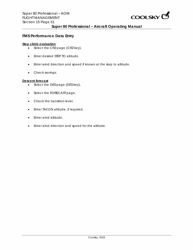
Super 80 Professional – AOM FLIGHT MANAGEMENT Section 15 Page 51
Super 80 Professional – Aircraft Operating Manual
Coolsky, 2018
FMS Performance Data Entry Step climb evaluation
• Select the CRZ page (CRZ key).
• Enter desired STEP TO altitude.
• Enter wind direction and speed if known at the step to altitude.
• Check savings.
Descent forecast • Select the DES page (DES key).
• Select the FORECAST page.
• Check the transition level.
• Enter TAI/ON altitude, if required.
• Enter wind altitude.
• Enter wind direction and speed for the altitude.
Super 80 Professional – AOM FUEL Section 16 Page 0
Super 80 Professional – Aircraft Operating Manual
Coolsky, 2018
SECTION 16
FUEL
Super 80 Professional – AOM FUEL Section 16 Page 1
Super 80 Professional – Aircraft Operating Manual
Coolsky, 2018
TABLE OF CONTENTS
SECTION 16: FUEL 0
TABLE OF CONTENTS ................................................................................................................. 1 GENERAL .................................................................................................................................... 2 CONTROLS AND INDICATORS ................................................................................................. 3 WARNING AND CAUTION INDICATORS ................................................................................. 6 FUEL DISTRIBUTION GUIDE......................................................................................................... 7
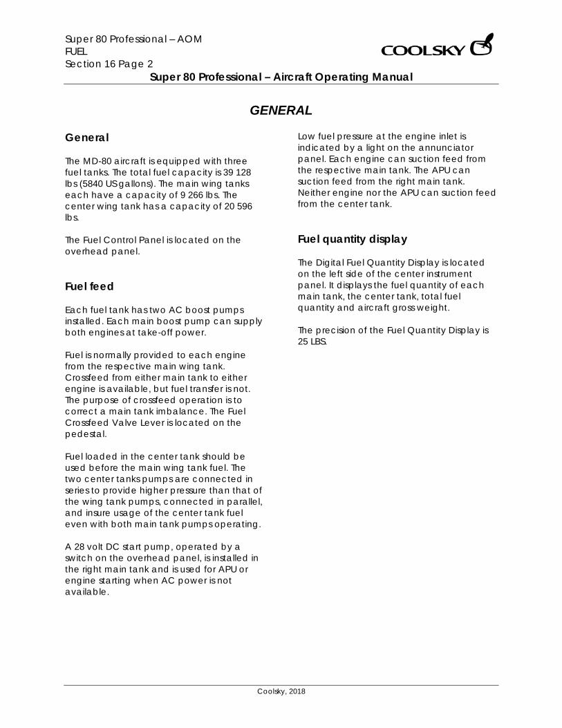
Super 80 Professional – AOM FUEL Section 16 Page 2
Super 80 Professional – Aircraft Operating Manual
Coolsky, 2018
GENERAL General The MD-80 aircraft is equipped with three fuel tanks. The total fuel capacity is 39 128 lbs (5840 US gallons). The main wing tanks each have a capacity of 9 266 lbs. The center wing tank has a capacity of 20 596 lbs. The Fuel Control Panel is located on the overhead panel. Fuel feed Each fuel tank has two AC boost pumps installed. Each main boost pump can supply both engines at take-off power. Fuel is normally provided to each engine from the respective main wing tank. Crossfeed from either main tank to either engine is available, but fuel transfer is not. The purpose of crossfeed operation is to correct a main tank imbalance. The Fuel Crossfeed Valve Lever is located on the pedestal. Fuel loaded in the center tank should be used before the main wing tank fuel. The two center tanks pumps are connected in series to provide higher pressure than that of the wing tank pumps, connected in parallel, and insure usage of the center tank fuel even with both main tank pumps operating. A 28 volt DC start pump, operated by a switch on the overhead panel, is installed in the right main tank and is used for APU or engine starting when AC power is not available.
Low fuel pressure at the engine inlet is indicated by a light on the annunciator panel. Each engine can suction feed from the respective main tank. The APU can suction feed from the right main tank. Neither engine nor the APU can suction feed from the center tank. Fuel quantity display The Digital Fuel Quantity Display is located on the left side of the center instrument panel. It displays the fuel quantity of each main tank, the center tank, total fuel quantity and aircraft gross weight. The precision of the Fuel Quantity Display is 25 LBS.
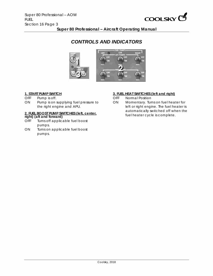
Super 80 Professional – AOM FUEL Section 16 Page 3
Super 80 Professional – Aircraft Operating Manual
Coolsky, 2018
CONTROLS AND INDICATORS
1. START PUMP SWITCH OFF Pump is off. ON Pump is on supplying fuel pressure to
the right engine and APU. 2. FUEL BOOST PUMP SWITCHES (left, center, right) (aft and forward) OFF Turns off applicable fuel boost
pumps. ON Turns on applicable fuel boost
pumps.
3. FUEL HEAT SWITCHES (left and right) OFF Normal Position ON Momentary. Turns on fuel heater for
left or right engine. The fuel heater is automatically switched off when the fuel heater cycle is complete.
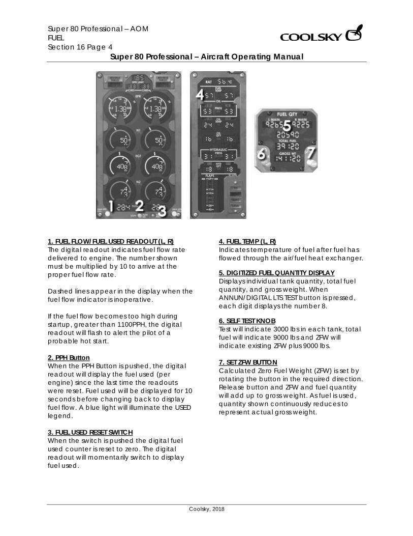
Super 80 Professional – AOM FUEL Section 16 Page 4
Super 80 Professional – Aircraft Operating Manual
Coolsky, 2018
1. FUEL FLOW/FUEL USED READOUT (L, R) The digital readout indicates fuel flow rate delivered to engine. The number shown must be multiplied by 10 to arrive at the proper fuel flow rate. Dashed lines appear in the display when the fuel flow indicator is inoperative. If the fuel flow becomes too high during startup, greater than 1100PPH, the digital readout will flash to alert the pilot of a probable hot start. 2. PPH Button When the PPH Button is pushed, the digital readout will display the fuel used (per engine) since the last time the readouts were reset. Fuel used will be displayed for 10 seconds before changing back to display fuel flow. A blue light will illuminate the USED legend. 3. FUEL USED RESET SWITCH When the switch is pushed the digital fuel used counter is reset to zero. The digital readout will momentarily switch to display fuel used.
4. FUEL TEMP (L, R) Indicates temperature of fuel after fuel has flowed through the air/fuel heat exchanger. 5. DIGITIZED FUEL QUANTITY DISPLAY Displays individual tank quantity, total fuel quantity, and gross weight. When ANNUN/DIGITAL LTS TEST button is pressed, each digit displays the number 8. 6. SELF TEST KNOB Test will indicate 3000 lbs in each tank, total fuel will indicate 9000 lbs and ZFW will indicate existing ZFW plus 9000 lbs. 7. SET ZFW BUTTON Calculated Zero Fuel Weight (ZFW) is set by rotating the button in the required direction. Release button and ZFW and fuel quantity will add up to gross weight. As fuel is used, quantity shown continuously reduces to represent actual gross weight.
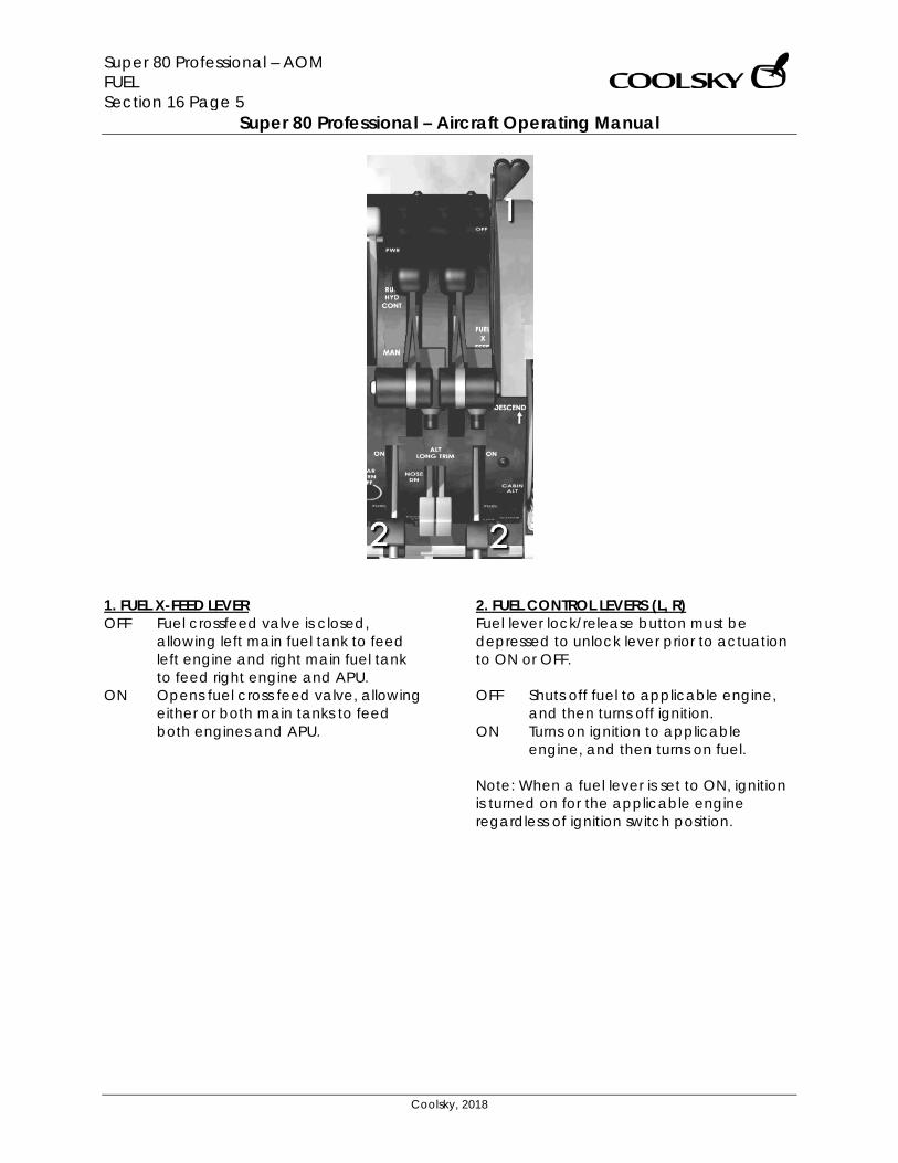
Super 80 Professional – AOM FUEL Section 16 Page 5
Super 80 Professional – Aircraft Operating Manual
Coolsky, 2018
1. FUEL X-FEED LEVER OFF Fuel crossfeed valve is closed,
allowing left main fuel tank to feed left engine and right main fuel tank to feed right engine and APU.
ON Opens fuel cross feed valve, allowing either or both main tanks to feed both engines and APU.
2. FUEL CONTROL LEVERS (L, R) Fuel lever lock/release button must be depressed to unlock lever prior to actuation to ON or OFF. OFF Shuts off fuel to applicable engine,
and then turns off ignition. ON Turns on ignition to applicable
engine, and then turns on fuel. Note: When a fuel lever is set to ON, ignition is turned on for the applicable engine regardless of ignition switch position.
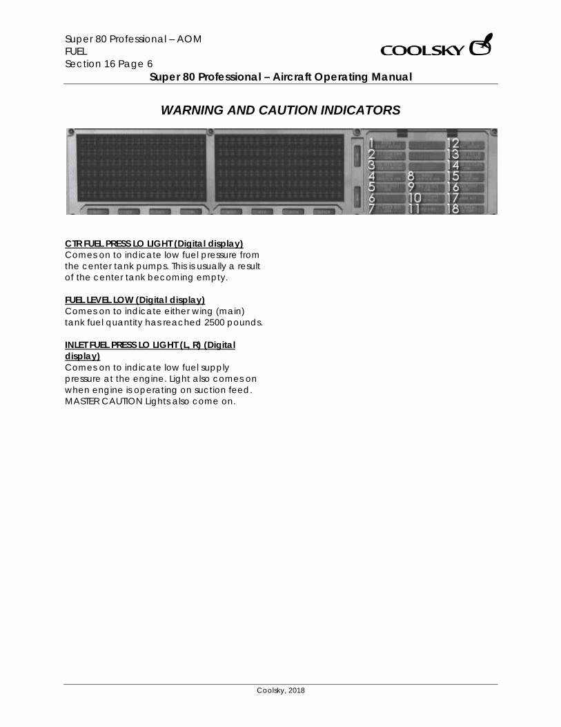
Super 80 Professional – AOM FUEL Section 16 Page 6
Super 80 Professional – Aircraft Operating Manual
Coolsky, 2018
WARNING AND CAUTION INDICATORS
CTR FUEL PRESS LO LIGHT (Digital display) Comes on to indicate low fuel pressure from the center tank pumps. This is usually a result of the center tank becoming empty. FUEL LEVEL LOW (Digital display) Comes on to indicate either wing (main) tank fuel quantity has reached 2500 pounds. INLET FUEL PRESS LO LIGHT (L, R) (Digital display) Comes on to indicate low fuel supply pressure at the engine. Light also comes on when engine is operating on suction feed. MASTER CAUTION Lights also come on.
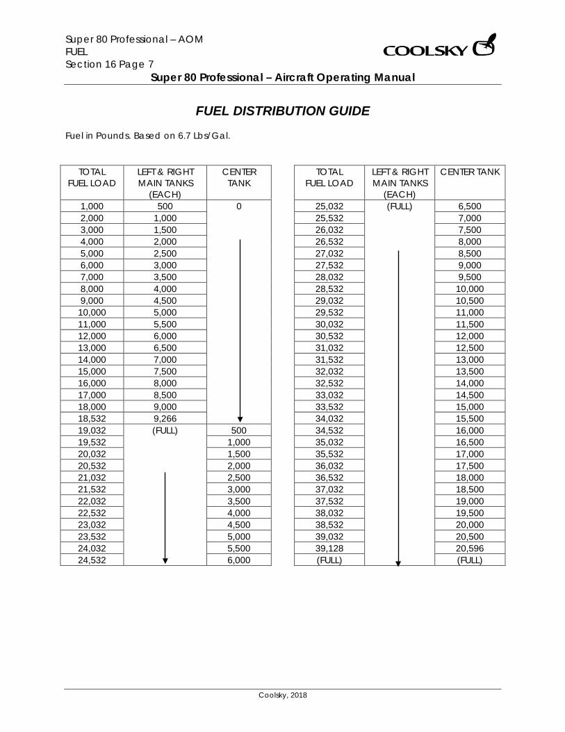
Super 80 Professional – AOM FUEL Section 16 Page 7
Super 80 Professional – Aircraft Operating Manual
Coolsky, 2018
FUEL DISTRIBUTION GUIDE Fuel in Pounds. Based on 6.7 Lbs/Gal.
TOTAL FUEL LOAD
LEFT & RIGHT MAIN TANKS
(EACH)
CENTER TANK
1,000 500 0 2,000 1,000 3,000 1,500 4,000 2,000 5,000 2,500 6,000 3,000 7,000 3,500 8,000 4,000 9,000 4,500
10,000 5,000 11,000 5,500 12,000 6,000 13,000 6,500 14,000 7,000 15,000 7,500 16,000 8,000 17,000 8,500 18,000 9,000 18,532 9,266 19,032 (FULL) 500 19,532 1,000 20,032 1,500 20,532 2,000 21,032 2,500 21,532 3,000 22,032 3,500 22,532 4,000 23,032 4,500 23,532 5,000 24,032 5,500 24,532 6,000
TOTAL FUEL LOAD
LEFT & RIGHT MAIN TANKS
(EACH)
CENTER TANK
25,032 (FULL) 6,500 25,532 7,000 26,032 7,500 26,532 8,000 27,032 8,500 27,532 9,000 28,032 9,500 28,532 10,000 29,032 10,500 29,532 11,000 30,032 11,500 30,532 12,000 31,032 12,500 31,532 13,000 32,032 13,500 32,532 14,000 33,032 14,500 33,532 15,000 34,032 15,500 34,532 16,000 35,032 16,500 35,532 17,000 36,032 17,500 36,532 18,000 37,032 18,500 37,532 19,000 38,032 19,500 38,532 20,000 39,032 20,500 39,128 20,596 (FULL) (FULL)
Super 80 Professional – AOM HYDRAULICS Section 17 Page 0
Super 80 Professional – Aircraft Operating Manual
Coolsky, 2018
SECTION 17
HYDRAULICS
Super 80 Professional – AOM HYDRAULICS Section 17 Page 1
Super 80 Professional – Aircraft Operating Manual
Coolsky, 2018
TABLE OF CONTENTS
SECTION 17: HYDRAULICS 0
TABLE OF CONTENTS ................................................................................................................. 1 GENERAL .................................................................................................................................... 2 CONTROLS AND INDICATORS ................................................................................................. 3 WARNING AND CAUTION INDICATORS ................................................................................. 4
Super 80 Professional – AOM HYDRAULICS Section 17 Page 2
Super 80 Professional – Aircraft Operating Manual
Coolsky, 2018
GENERAL The MD-80 hydraulic system consists of independent left and right systems. Each system has a reservoir and is pressurized by a single engine-driven pump. Hydraulic Supply The left and right hydraulics reservoir is located in the left and right main gear wheel wells. Each reservoir supplies fluid to its own system respectively. Hydraulic Pumps The left hydraulic system is pressurized by a pump mounted on the left engine and the right hydraulic system is pressurized by a pump mounted on the right engine. Each of the engine-driven pumps can operate in a high pressure or low pressure mode. The high pressure mode provides 3000 PSI and is used for taxi, take-off and landing. The low pressure mode provides 1500 PSI and is selected on the After Take-off Checklist to reduce wear on the system. An auxiliary, electrical pump is installed in the right hydraulic system and is designed for continuous operation at 3000 PSI. A power transfer pump is installed to transfer pressure between the left and right hydraulic system. Note that there is no transfer of fluid between the left and right hydraulic system. For the transfer pump to operate, either the left or right system must be pressurized to provide energy to drive the transfer pump. The transfer pump is normally used during taxi, take-off and landing as a backup source of pressure.
Hydraulic System Fluids Standard:
Chevron Hyjet IVA Substitutes:
Chevron Hyjet IV Monsanto Skydrol 500B4 Skydrol LD4
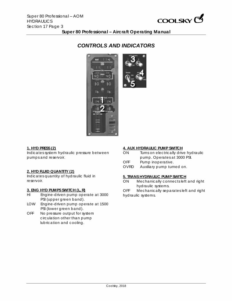
Super 80 Professional – AOM HYDRAULICS Section 17 Page 3
Super 80 Professional – Aircraft Operating Manual
Coolsky, 2018
CONTROLS AND INDICATORS
1. HYD PRESS (2) Indicates system hydraulic pressure between pumps and reservoir. 2. HYD FLUID QUANTITY (2) Indicates quantity of hydraulic fluid in reservoir. 3. ENG HYD PUMPS SWITCH (L, R) HI Engine-driven pump operate at 3000
PSI (upper green band). LOW Engine-driven pump operate at 1500
PSI (lower green band). OFF No pressure output for system
circulation other than pump lubrication and cooling.
4. AUX HYDRAULIC PUMP SWITCH ON Turns on electrically drive hydraulic
pump. Operates at 3000 PSI. OFF Pump inoperative. OVRD Auxiliary pump turned on. 5. TRANS HYDRAULIC PUMP SWITCH ON Mechanically connects left and right
hydraulic systems. OFF Mechanically separates left and right hydraulic systems.
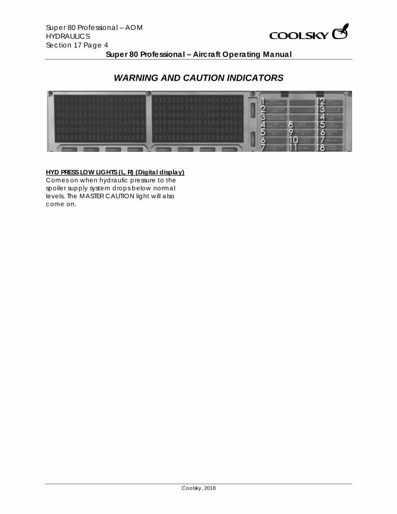
Super 80 Professional – AOM HYDRAULICS Section 17 Page 4
Super 80 Professional – Aircraft Operating Manual
Coolsky, 2018
WARNING AND CAUTION INDICATORS
HYD PRESS LOW LIGHTS (L, R) (Digital display) Comes on when hydraulic pressure to the spoiler supply system drops below normal levels. The MASTER CAUTION light will also come on.
Super 80 Professional – AOM LANDING GEAR Section 18 Page 0
Super 80 Professional – Aircraft Operating Manual
Coolsky, 2018
SECTION 18
LANDING GEAR
Super 80 Professional – AOM LANDING GEAR Section 18 Page 1
Super 80 Professional – Aircraft Operating Manual
Coolsky, 2018
TABLE OF CONTENTS
SECTION 18: LANDING GEAR 0
TABLE OF CONTENTS ................................................................................................................. 1 GENERAL .................................................................................................................................... 2 CONTROLS AND INDICATORS ................................................................................................. 5 WARNING AND CAUTION INDICATORS ................................................................................. 9
Super 80 Professional – AOM LANDING GEAR Section 18 Page 2
Super 80 Professional – Aircraft Operating Manual
Coolsky, 2018
GENERAL The airplane is equipped with a fully retractable tricycle landing gear consisting of nose gear and main gear assemblies. The landing gear is actuated by the landing gear handle. When retracted, the landing gear is fully enclosed by doors. In case of a hydraulics failure, the landing gear may be mechanically released to freefall to the extended locked position. Braking is provided by dual hydraulic multi-disc wheel brakes with anti-skid systems (ABS) on the main gears. A visual and aural indicating and warning system provides indication of gear and brake system status. Spray deflectors are installed on both main gear and nose gear assemblies to minimize water and slush ingestion on take-off and landing. A tail bumper assembly, mounted on the bottom of the aft fuselage, prevents structural damage if the aft fuselage should make contact with the ground. Nose Gear The nose gear assembly is steerable, has dual wheels, and is mounted in a wheel well in the forward lower section of the nose of the airplane. A ground shift mechanism, mounted on the nose gear strut, is operated by compression and extension of the nose gear strut. This mechanism is used to establish ground or flight modes of operation. Nose Gear Doors
The nose gear wheel well doors consist of two forward doors and to aft doors. The forward doors are closed when the gear is extended. Nose Wheel Steering The nose wheel steering system is hydraulically controlled through a full range of 164 degrees, 82 degrees to either side of center, by a steering wheel located on the captain’s left console. When the steering cylinders are in the neutral position, they act as shimmy dampers. Main Gear The airplane is equipped with two main landing gear and one nose gear, all with dual wheels and locks mounted on a shock strut. When extended, each main landing gear is locked down by over-center linkage. When retracted, the main landing gear assemblies are held up by hydraulic pressure, providing the engine driven pumps are selected to supply 3000 PSI. If the pumps are selected to supply 1500 PSI, the main gear will rest upon the doors. If hydraulic power is unavailable for gear extension, the main gear doors latches may be released by the emergency gear extension lever.
Super 80 Professional – AOM LANDING GEAR Section 18 Page 3
Super 80 Professional – Aircraft Operating Manual
Coolsky, 2018
Main Gear Doors The main gear doors consist of a hydraulically operated main door and a mechanically operated outboard door. The main gear doors are mechanically latched when closed. The main gear doors cycle to the closed position when the gear is approaching the extended position. Visual/aural Indicating and Warning System The landing gear position and status is indicated by annunciator lights on the upper main instrument panel. Three landing gear position lights come on green to indicate that the landing gear is down and locked. The lights will come on red when the landing gear is in any intermediate position. The landing gear door annunciator will come one anytime either of the main landing gear doors are not closed and latched. The landing gear warning horn and vocal warning will sound when the airplane is at or below 210 KTS and either one of the throttles are closed and the landing gear handle is not in the down position. The landing gear warning horn and vocal warning will also sound whenever the flaps are extended to beyond 26 degrees and the landing gear handle is not in the down position. Reference markings on each main gear landing gear over-center linkage provide visual confirmation that the landing gear is down and locked. Nose gear verification is provided by a green indicator pin on the pedestal just behind the throttle quadrant. Brakes Each main gear wheel is fitted with a dual system, disc-type power brake. Each brake contains two independent cylinder and
passageway systems. Each system contains four hydraulic cylinders, one bleed port and one hydraulic pressure port. The wheel brakes are controlled by two completely independent hydraulic brake systems. Each system is capable of supplying reserve brake pressure in the event of a hydraulic pressure failure in the other system. The airplane wheel brakes may be mechanically applied by depressing the brake pedals. A fully automatic anti-skid system is installed to obtain a more effective braking application, through control of wheel rotation at the point of maximum braking efficiency. The system is deactivated whenever the landing gear handle is not in the down detent, parking brakes set, arm switch at OFF, or airplane is at low taxi speeds. Both main landing gear wheels and nose gear wheel are fitted with spin brakes. The purpose of the spin brake is to stop the tire rotation after take-off. A gauge and annunciator light proved visual indication of brake temperature. The parking brakes are set by pulling up the park brake control knob (located on the captain’s left console). Park brake on is indicated by an annunciator light on the overhead panel. If the throttles are advanced to a take-off setting with the parking brake set, the aural/vocal warning system will be activated.
Super 80 Professional – AOM LANDING GEAR Section 18 Page 4
Super 80 Professional – Aircraft Operating Manual
Coolsky, 2018
Automatic Brake System (ABS) The Automatic Brake System (ABS) is an electrically controlled means of automatically applying the brakes in order to maintain a constant level of deceleration. The ABS has two modes of operation; landing mode and take-off mode. The landing mode provides pilot selection of three levels of deceleration; MIN, MED, and MAX. In the MIN and MED position, the system compares actual airplane deceleration with the pilot’s selection. In the MAX position, full brake system pressure is applied to the brakes and maximum deceleration is limited to anti-skid system operation. During the rollout from a landing or rejected take-off, the Auto Brake System will automatically disarm under the following conditions:
• Brakes are applied manually by the flight crew.
• Speed brakes are stowed. • Either throttle is advanced. • Airplane comes to a full stop.
When the ABS disarms, the ABS light on the glareshield will come on. The take-off warning horn and vocal (‘AUTO BRAKE’) will sound if the AUTO BRAKE selector is in a position other than TO with the Spoiler Lever armed.
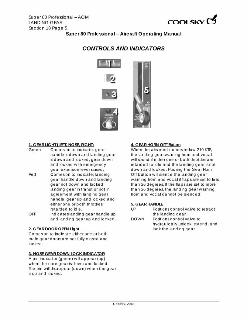
Super 80 Professional – AOM LANDING GEAR Section 18 Page 5
Super 80 Professional – Aircraft Operating Manual
Coolsky, 2018
CONTROLS AND INDICATORS
1. GEAR LIGHT (LEFT, NOSE, RIGHT) Green Comes on to indicate: gear
handle is down and landing gear is down and locked; gear down and locked with emergency gear extension lever raised.
Red Comes on to indicate; landing gear handle down and landing gear not down and locked; landing gear in transit or not in agreement with landing gear handle; gear up and locked and either one or both throttles retarded to idle.
OFF Indicates landing gear handle up and landing gear up and locked.
2. GEAR DOOR OPEN Light Comes on to indicate either one or both main gear doors are not fully closed and locked. 3. NOSE GEAR DOWN LOCK INDICATOR A pin indicator (green) will appear (up) when the nose gear is down and locked. The pin will disappear (down) when the gear is up and locked.
4. GEAR HORN OFF Button When the airspeed comes below 210 KTS, the landing gear warning horn and vocal will sound if either one or both throttles are retarded to idle and the landing gear is not down and locked. Pushing the Gear Horn Off button will silence the landing gear warning horn and vocal if flaps are set to less than 26 degrees. If the flaps are set to more than 26 degrees, the landing gear warning horn and vocal cannot be silenced. 5. GEAR HANDLE UP Positions control valve to retract
the landing gear. DOWN Positions control valve to
hydraulically unlock, extend, and lock the landing gear.
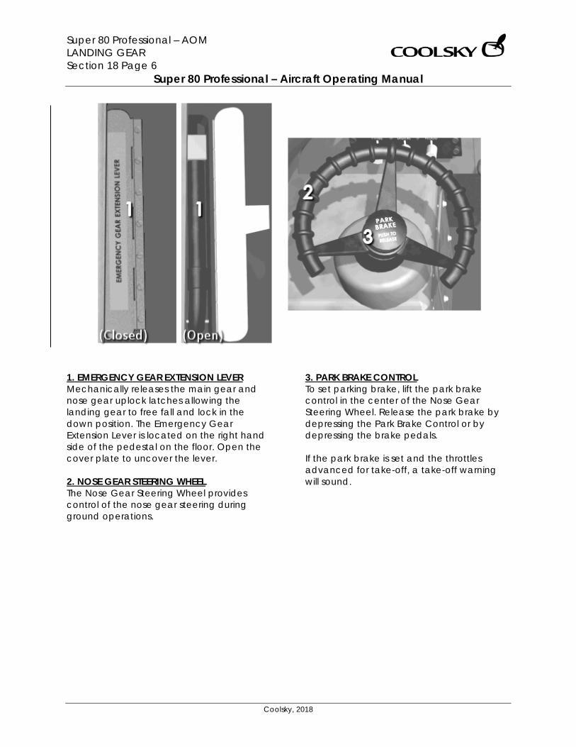
Super 80 Professional – AOM LANDING GEAR Section 18 Page 6
Super 80 Professional – Aircraft Operating Manual
Coolsky, 2018
1. EMERGENCY GEAR EXTENSION LEVER Mechanically releases the main gear and nose gear uplock latches allowing the landing gear to free fall and lock in the down position. The Emergency Gear Extension Lever is located on the right hand side of the pedestal on the floor. Open the cover plate to uncover the lever. 2. NOSE GEAR STEERING WHEEL The Nose Gear Steering Wheel provides control of the nose gear steering during ground operations.
3. PARK BRAKE CONTROL To set parking brake, lift the park brake control in the center of the Nose Gear Steering Wheel. Release the park brake by depressing the Park Brake Control or by depressing the brake pedals. If the park brake is set and the throttles advanced for take-off, a take-off warning will sound.
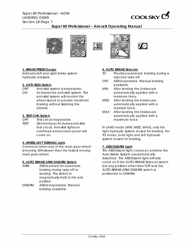
Super 80 Professional – AOM LANDING GEAR Section 18 Page 7
Super 80 Professional – Aircraft Operating Manual
Coolsky, 2018
1. BRAKE PRESS Gauge Indicates left and right brake system hydraulic pressure. 2. ANTI-SKID Switch OFF Anti-skid system is inoperative. ON Activates the anti-skid system. The
anti-skid system will monitor the wheel speed to provide maximum braking without skidding the wheels.
3. TEST CHK Switch OFF Test circuit inoperative. TEST (Momentary) Activates anti-skid
test circuit. Anti-skid lights on overhead annunciator panel will come on.
4. WHEEL NOT TURNING Light Comes on when any of the main gear wheel is moving 20% slower than the fastest moving main gear wheel. 5. AUTO BRAKE ARM/DISARM Switch ARM ABS is armed for automatic
braking during take-off or landing. The switch is magnetically held in the arm position.
DISARM ABS is inoperative. Manual braking available.
6. AUTO BRAKE Selector TO Provides automatic braking during a
rejected take-off. OFF ABS inoperative. Manual braking
available. MIN After landing the brakes are
automatically applied with a minimum force.
MED After landing the brakes are automatically applied with a medium force.
MAX After landing the brakes are automatically applied with a maximum force.
In LAND mode (MIN, MED, MAX), only the right hydraulic system is used for braking. For TO mode, both right and left hydraulic system is used for braking. 7. ABS DISARM Light The ABS Disarm light comes on anytime the Auto Brake System is automatically disarmed. The ABS Disarm light will also come on if the AUTO BRAKE Selector switch is in any position other than OFF and the AUTO BRAKE ARM/DISARM switch is positioned to DISARM.
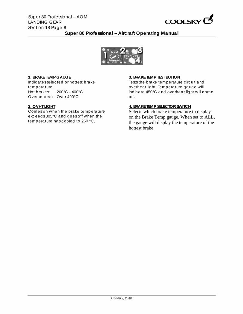
Super 80 Professional – AOM LANDING GEAR Section 18 Page 8
Super 80 Professional – Aircraft Operating Manual
Coolsky, 2018
1. BRAKE TEMP GAUGE Indicates selected or hottest brake temperature. Hot brakes: 200°C - 400°C Overheated: Over 400°C 2. OVHT LIGHT Comes on when the brake temperature exceeds 305°C and goes off when the temperature has cooled to 260 °C.
3. BRAKE TEMP TEST BUTTON Tests the brake temperature circuit and overheat light. Temperature gauge will indicate 450°C and overheat light will come on. 4. BRAKE TEMP SELECTOR SWITCH Selects which brake temperature to display on the Brake Temp gauge. When set to ALL, the gauge will display the temperature of the hottest brake.
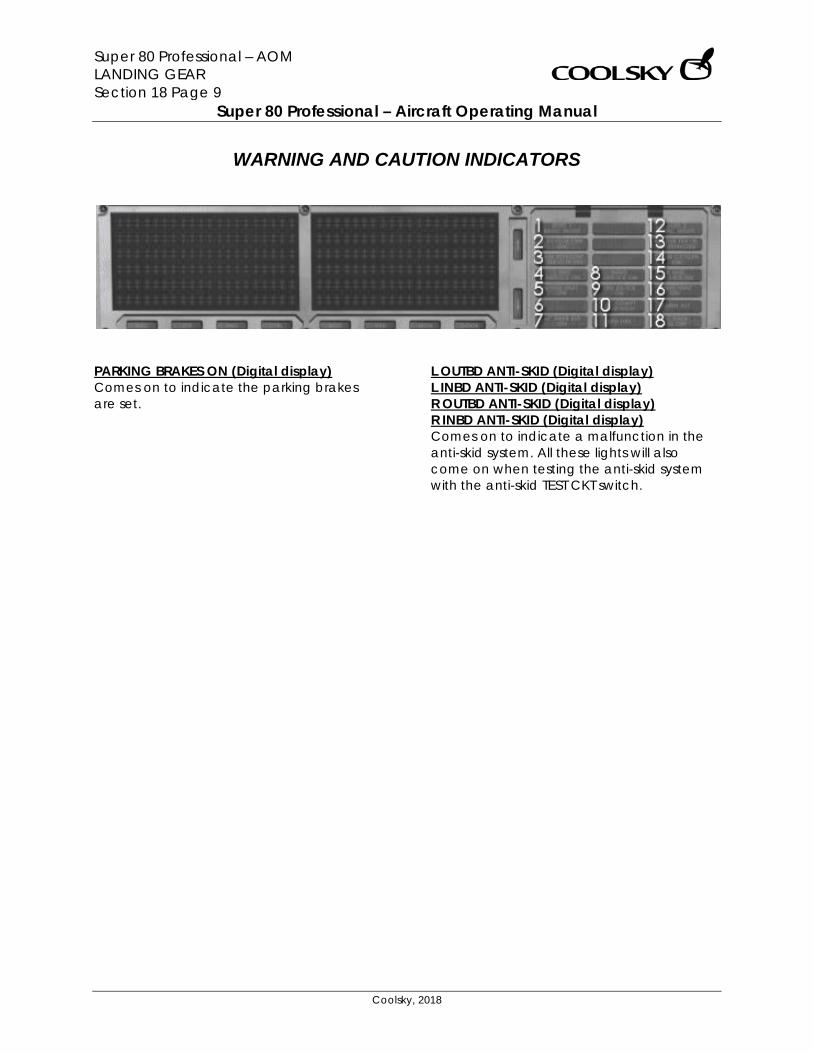
Super 80 Professional – AOM LANDING GEAR Section 18 Page 9
Super 80 Professional – Aircraft Operating Manual
Coolsky, 2018
WARNING AND CAUTION INDICATORS
PARKING BRAKES ON (Digital display) Comes on to indicate the parking brakes are set.
L OUTBD ANTI-SKID (Digital display) L INBD ANTI-SKID (Digital display) R OUTBD ANTI-SKID (Digital display) R INBD ANTI-SKID (Digital display) Comes on to indicate a malfunction in the anti-skid system. All these lights will also come on when testing the anti-skid system with the anti-skid TEST CKT switch.
Super 80 Professional – AOM MISCELLANEOUS Section 19 Page 0
Super 80 Professional – Aircraft Operating Manual
Coolsky, 2018
SECTION 19
MISCELLANEOUS
Super 80 Professional – AOM MISCELLANEOUS Section 19 Page 1
Super 80 Professional – Aircraft Operating Manual
Coolsky, 2018
TABLE OF CONTENTS
SECTION 19: MISCELLANEOUS 0
TABLE OF CONTENTS ................................................................................................................. 1 EXTERIOR LIGHTING ................................................................................................................... 2 COCKPIT LIGHTING ................................................................................................................... 3 VOICE RECORDER .................................................................................................................... 5 ELECTRONIC OVERHEAD ANNUNCIATON PANEL (EOAP) .................................................. 6
Warning and Advisory Lights ............................................................................................ 7 Electrical Warnings ............................................................................................................ 8 Engine Warnings ................................................................................................................ 8 Flight Controls Warnings ................................................................................................... 9 Miscellaneous Warnings ................................................................................................... 9 Hydraulic Warnings ........................................................................................................... 9 Monitor Warning .............................................................................................................. 10 Door Warnings ................................................................................................................. 10
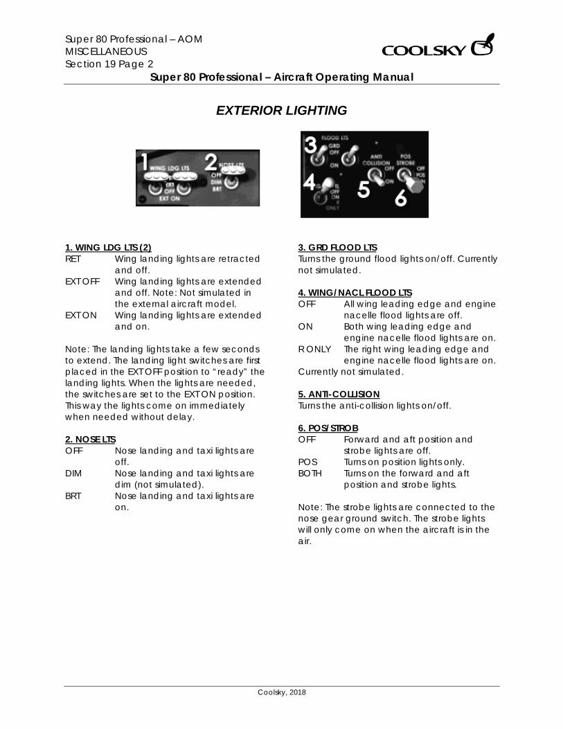
Super 80 Professional – AOM MISCELLANEOUS Section 19 Page 2
Super 80 Professional – Aircraft Operating Manual
Coolsky, 2018
EXTERIOR LIGHTING
1. WING LDG LTS (2) RET Wing landing lights are retracted
and off. EXT OFF Wing landing lights are extended
and off. Note: Not simulated in the external aircraft model.
EXT ON Wing landing lights are extended and on.
Note: The landing lights take a few seconds to extend. The landing light switches are first placed in the EXT OFF position to “ready” the landing lights. When the lights are needed, the switches are set to the EXT ON position. This way the lights come on immediately when needed without delay. 2. NOSE LTS OFF Nose landing and taxi lights are
off. DIM Nose landing and taxi lights are
dim (not simulated). BRT Nose landing and taxi lights are
on.
3. GRD FLOOD LTS Turns the ground flood lights on/off. Currently not simulated. 4. WING/NACL FLOOD LTS OFF All wing leading edge and engine
nacelle flood lights are off. ON Both wing leading edge and
engine nacelle flood lights are on. R ONLY The right wing leading edge and
engine nacelle flood lights are on. Currently not simulated. 5. ANTI-COLLISION Turns the anti-collision lights on/off. 6. POS/STROB OFF Forward and aft position and
strobe lights are off. POS Turns on position lights only. BOTH Turns on the forward and aft
position and strobe lights. Note: The strobe lights are connected to the nose gear ground switch. The strobe lights will only come on when the aircraft is in the air.
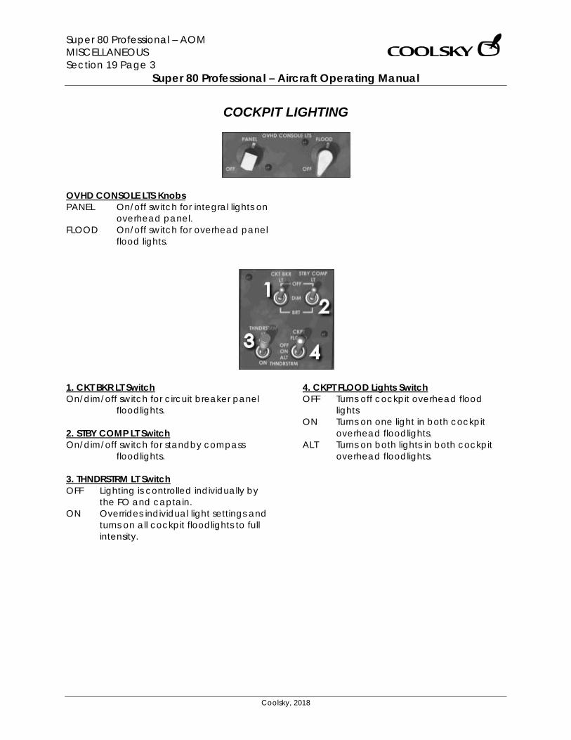
Super 80 Professional – AOM MISCELLANEOUS Section 19 Page 3
Super 80 Professional – Aircraft Operating Manual
Coolsky, 2018
COCKPIT LIGHTING
OVHD CONSOLE LTS Knobs PANEL On/off switch for integral lights on
overhead panel. FLOOD On/off switch for overhead panel
flood lights.
1. CKT BKR LT Switch On/dim/off switch for circuit breaker panel
floodlights. 2. STBY COMP LT Switch On/dim/off switch for standby compass
floodlights. 3. THNDRSTRM LT Switch OFF Lighting is controlled individually by
the FO and captain. ON Overrides individual light settings and
turns on all cockpit floodlights to full intensity.
4. CKPT FLOOD Lights Switch OFF Turns off cockpit overhead flood
lights ON Turns on one light in both cockpit
overhead floodlights. ALT Turns on both lights in both cockpit
overhead floodlights.
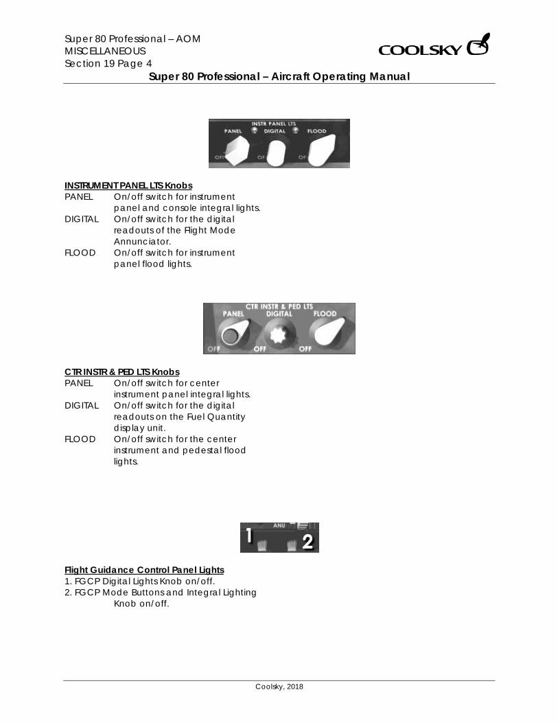
Super 80 Professional – AOM MISCELLANEOUS Section 19 Page 4
Super 80 Professional – Aircraft Operating Manual
Coolsky, 2018
INSTRUMENT PANEL LTS Knobs PANEL On/off switch for instrument
panel and console integral lights. DIGITAL On/off switch for the digital
readouts of the Flight Mode Annunciator.
FLOOD On/off switch for instrument panel flood lights.
CTR INSTR & PED LTS Knobs PANEL On/off switch for center
instrument panel integral lights. DIGITAL On/off switch for the digital
readouts on the Fuel Quantity display unit.
FLOOD On/off switch for the center instrument and pedestal flood lights.
Flight Guidance Control Panel Lights 1. FGCP Digital Lights Knob on/off. 2. FGCP Mode Buttons and Integral Lighting
Knob on/off.

Super 80 Professional – AOM MISCELLANEOUS Section 19 Page 5
Super 80 Professional – Aircraft Operating Manual
Coolsky, 2018
VOICE RECORDER
1. COCKPIT MONITOR MICROPHONE Actuated by audible sounds in the cockpit. Sounds are transmitted from the microphone to a recorder containing a 30 minute loop tape. 2. TEST Button When pushed a test signal is sent to the recorder at 0.8 seconds interval for each of the four channels. The test cycle is completed in 5 seconds. 3. ERASE Button When the Erase button is pushed and held for more than 2 seconds, the tape will be erased. The aircraft must be on the ground and the parking brakes must be engaged for this feature to be enabled. (Currently not simulated)
4. HEADSET Jack When a headset is plugged in and the test button is pushed, a 600Hz tone indicates that the system is operational. 5. TEST MONITOR METER The Test Monitor Meter indicates recording level during test. A minimum recording level of 8 should be indicated by the needle. A reading of zero indicates a failure of respective channel.
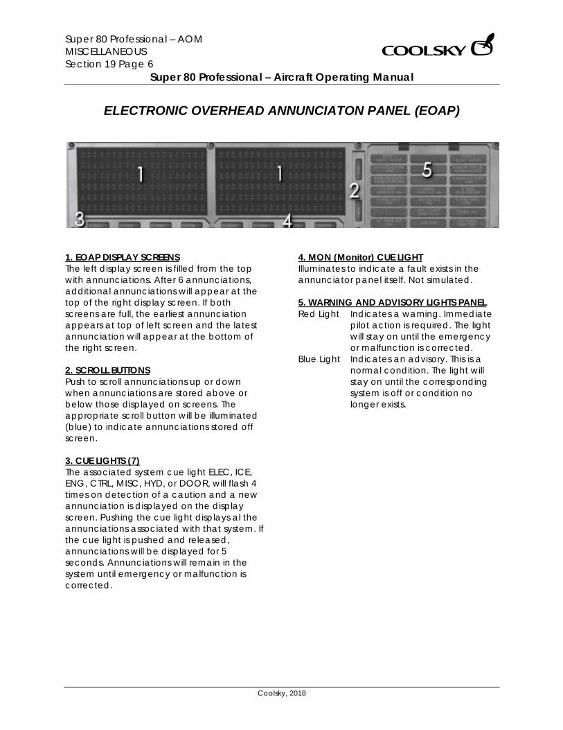
Super 80 Professional – AOM MISCELLANEOUS Section 19 Page 6
Super 80 Professional – Aircraft Operating Manual
Coolsky, 2018
ELECTRONIC OVERHEAD ANNUNCIATON PANEL (EOAP)
1. EOAP DISPLAY SCREENS The left display screen is filled from the top with annunciations. After 6 annunciations, additional annunciations will appear at the top of the right display screen. If both screens are full, the earliest annunciation appears at top of left screen and the latest annunciation will appear at the bottom of the right screen. 2. SCROLL BUTTONS Push to scroll annunciations up or down when annunciations are stored above or below those displayed on screens. The appropriate scroll button will be illuminated (blue) to indicate annunciations stored off screen. 3. CUE LIGHTS (7) The associated system cue light ELEC, ICE, ENG, CTRL, MISC, HYD, or DOOR, will flash 4 times on detection of a caution and a new annunciation is displayed on the display screen. Pushing the cue light displays al the annunciations associated with that system. If the cue light is pushed and released, annunciations will be displayed for 5 seconds. Annunciations will remain in the system until emergency or malfunction is corrected.
4. MON (Monitor) CUE LIGHT Illuminates to indicate a fault exists in the annunciator panel itself. Not simulated. 5. WARNING AND ADVISORY LIGHTS PANEL Red Light Indicates a warning. Immediate
pilot action is required. The light will stay on until the emergency or malfunction is corrected.
Blue Light Indicates an advisory. This is a normal condition. The light will stay on until the corresponding system is off or condition no longer exists.
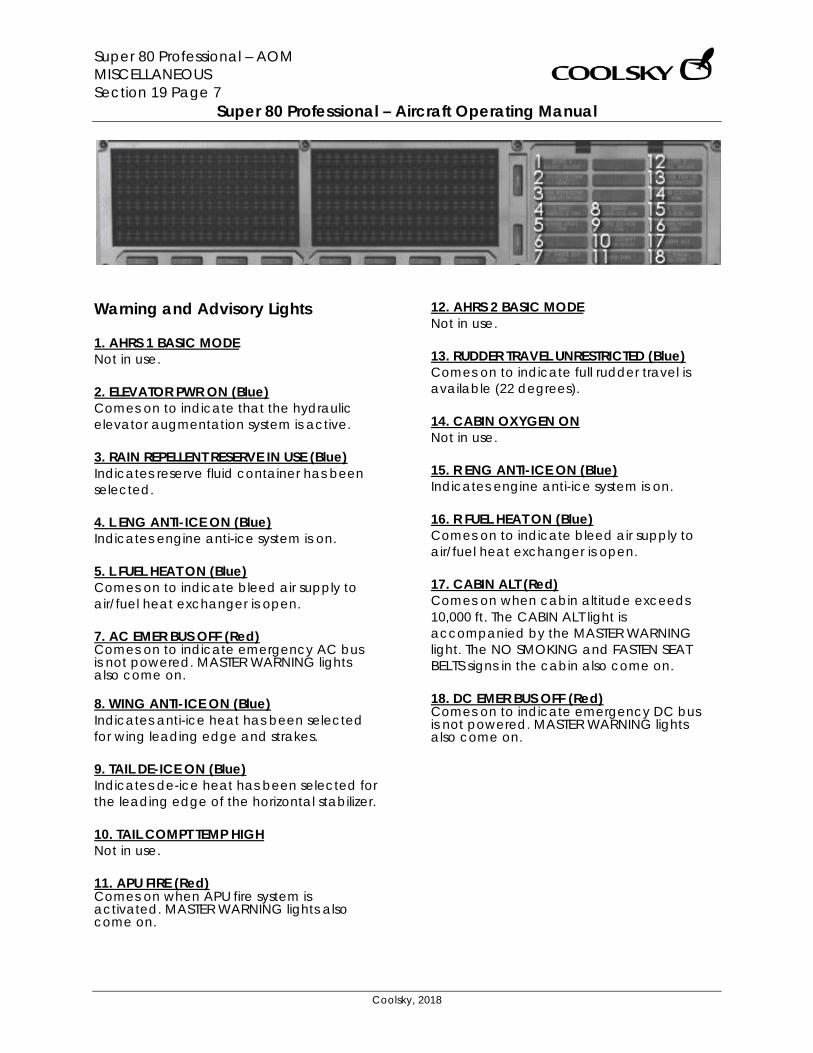
Super 80 Professional – AOM MISCELLANEOUS Section 19 Page 7
Super 80 Professional – Aircraft Operating Manual
Coolsky, 2018
Warning and Advisory Lights 1. AHRS 1 BASIC MODE Not in use. 2. ELEVATOR PWR ON (Blue) Comes on to indicate that the hydraulic elevator augmentation system is active. 3. RAIN REPELLENT RESERVE IN USE (Blue) Indicates reserve fluid container has been selected. 4. L ENG ANTI-ICE ON (Blue) Indicates engine anti-ice system is on. 5. L FUEL HEAT ON (Blue) Comes on to indicate bleed air supply to air/fuel heat exchanger is open. 7. AC EMER BUS OFF (Red) Comes on to indicate emergency AC bus is not powered. MASTER WARNING lights also come on. 8. WING ANTI-ICE ON (Blue) Indicates anti-ice heat has been selected for wing leading edge and strakes. 9. TAIL DE-ICE ON (Blue) Indicates de-ice heat has been selected for the leading edge of the horizontal stabilizer. 10. TAIL COMPT TEMP HIGH Not in use. 11. APU FIRE (Red) Comes on when APU fire system is activated. MASTER WARNING lights also come on.
12. AHRS 2 BASIC MODE Not in use. 13. RUDDER TRAVEL UNRESTRICTED (Blue) Comes on to indicate full rudder travel is available (22 degrees). 14. CABIN OXYGEN ON Not in use. 15. R ENG ANTI-ICE ON (Blue) Indicates engine anti-ice system is on. 16. R FUEL HEAT ON (Blue) Comes on to indicate bleed air supply to air/fuel heat exchanger is open. 17. CABIN ALT (Red) Comes on when cabin altitude exceeds 10,000 ft. The CABIN ALT light is accompanied by the MASTER WARNING light. The NO SMOKING and FASTEN SEAT BELTS signs in the cabin also come on. 18. DC EMER BUS OFF (Red) Comes on to indicate emergency DC bus is not powered. MASTER WARNING lights also come on.
Super 80 Professional – AOM MISCELLANEOUS Section 19 Page 8
Super 80 Professional – Aircraft Operating Manual
Coolsky, 2018
Electrical Warnings APU GEN OFF LIGHT Comes on to indicate APU is operating but APU generator is not in use. MASTER CAUTION lights also come on. AC BUS OFF LIGHT (L, R) Comes on to indicate generator bus is not powered. MASTER CAUTION lights also come on. GEN OFF LIGHT (L, R) Comes on to indicate generator relay is open, disconnecting generator from its bus. MASTER CAUTION lights also come on. AC CROSSTIE LOCKOUT Comes on to indicate AC crosstie relay is locked open and automatic AC crosstie is inoperative. MASTER CAUTION lights also come on. BATTERY OFF LIGHT Amber light that comes on when Battery switch is in the OFF position. DC BUS OFF Comes on to indicate either left or right DC bus is not powered. MASTER CAUTION lights also come on.
Engine Warnings ENG SYNC ON Comes on to indicate ENG SYNC switch is selected to N1 or N2 when landing gear handle is in the down position. START VALVE OPEN (L, R) Comes on to indicate the engine starter valve is open, allowing bleed air to flow into the compressor stage of the turbine. INLET FUEL PRESS LO LIGHT (L, R) Comes on to indicate low fuel supply pressure at the engine. Light also comes on when engine is operating on suction feed. MASTER CAUTION Lights also come on. CTR FUEL PRESS LO Comes on to indicate low fuel pressure from the center tank pumps. This is usually a result of the center tank becoming empty. ART INOP Comes on to indicate a failure has been detected in the ART system, or the ART switch is in the OFF position. CSD OIL PRESS LOW LIGHT (L, R) Comes on to indicate oil pressure in CSD is below operating limits. MASTER CAUTION lights also come on.
Super 80 Professional – AOM MISCELLANEOUS Section 19 Page 9
Super 80 Professional – Aircraft Operating Manual
Coolsky, 2018
Flight Controls Warnings YAW DAMP OFF Comes on to indicate Yaw damper is not operating. SPOILER/FLAP EXTENDED Comes on to indicate speedbrakes are extended with flaps extended beyond 6 degrees. MASTER CAUTION light will also come on. The light will not come on when on the ground. RUDDER CONTROL MANUAL Comes on to indicate there is no hydraulic power to the rudder. SPOILER DEPLOYED Comes on to indicate Ground Spoiler is extended in flight, or any spoiler is deployed on the ground with the spoiler lever in the stowed position. MACH TRIM INOP Light (Amber) Comes on to indicate Mach trim compensator is off, or Mach Trim Comp switch is in the OVRD position.
Miscellaneous Warnings FUEL LEVEL LOW Comes on to indicate either wing (main) tank fuel quantity has reached 2500 pounds. PITOT/STALL HEATER OFF Comes on to indicate METER SEL & HEATER selector in OFF. MASTER CAUTION light also comes on. APU OIL PRESS LOW Comes on the APU oil pressure is too low. The light should come on during APU start. EMER LIGHT NOT ARMED Comes on to indicate the Emergency Lights switch is out of the ARM position. FLIGHT RECORDER OFF Comes on to indicate the Flight Data Recorder is still off after brakes release. Hydraulic Warnings PARKING BRAKES ON Comes on to indicate the parking brakes are set. HYD PRESS LOW LIGHTS (L, R) Comes on when hydraulic pressure to the spoiler supply system drops below normal levels. The MASTER CAUTION light will also come on. OUTBD ANTI-SKID (L, R) Comes on to indicate a malfunction in the anti-skid system. The light will also come on when testing the anti-skid system with the anti-skid TEST CKT switch. INBD ANTI-SKID (L, R) Comes on to indicate a malfunction in the anti-skid system. The light will also come on when testing the anti-skid system with the anti-skid TEST CKT switch.
Super 80 Professional – AOM MISCELLANEOUS Section 19 Page 10
Super 80 Professional – Aircraft Operating Manual
Coolsky, 2018
GPWS FAIL Comes on to indicate that the Ground Proximity Warning System is inoperative. The light will also come on when testing the GPWS. FIRE DETECTION LOOP Light (Amber) Comes on when testing the Fire Detection system. Monitor Warning Not simulated.
Door Warnings AFT STAIRWAY DOOR Comes on to indicate the aft stairway door is open. AFT CABIN DOOR Comes on to indicate the aft cabin door is open. AFT GALLEY DOOR Comes on to indicate the aft galley door is open. FWD STAIRWAY DOOR Comes on to indicate the forward stairway door is open. FWD CABIN DOOR Comes on to indicate the cabin stairway door is open. AFT CARGO DOOR Comes on to indicate the aft cargo door is open. MID CARGO DOOR Comes on to indicate the mid cargo door is open. FWD CARGO DOOR Comes on to indicate the forward cargo door is open. FWD GALLEY DOOR Comes on to indicate the forward galley door is open.
Super 80 Professional – AOM NAVIGATION Section 20 Page 0
Super 80 Professional – Aircraft Operating Manual
Coolsky, 2018
SECTION 20
NAVIGATION
Super 80 Professional – AOM NAVIGATION Section 20 Page 1
Super 80 Professional – Aircraft Operating Manual
Coolsky, 2018
TABLE OF CONTENTS
SECTION 20: NAVIGATION 0
TABLE OF CONTENTS ................................................................................................................. 1 GENERAL .................................................................................................................................... 2 VHF NAV CONTROL PANEL AND ADF CONTROL PANEL ..................................................... 3 RADIO DISTANCE MAGNETIC INDICATOR (RDMI) ............................................................................ 4 NAVIGATION DISPLAY (ROSE MODE) .............................................................................................. 5 NAVIGATION DISPLAY (ARC MODE) ............................................................................................... 6 NAVIGATION DISPLAY (MAP MODE) ............................................................................................... 8 NAVIGATION DISPLAY (PLAN MODE) .............................................................................................. 9 MODE SELECTOR CONTROL PANEL & MAG/TRUE LIGHT .................................................. 10
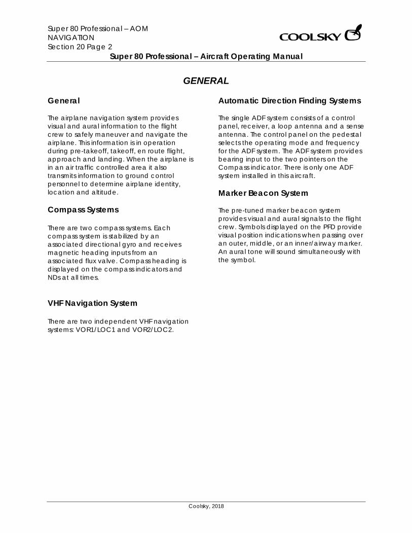
Super 80 Professional – AOM NAVIGATION Section 20 Page 2
Super 80 Professional – Aircraft Operating Manual
Coolsky, 2018
GENERAL General The airplane navigation system provides visual and aural information to the flight crew to safely maneuver and navigate the airplane. This information is in operation during pre-takeoff, takeoff, en route flight, approach and landing. When the airplane is in an air traffic controlled area it also transmits information to ground control personnel to determine airplane identity, location and altitude. Compass Systems There are two compass systems. Each compass system is stabilized by an associated directional gyro and receives magnetic heading inputs from an associated flux valve. Compass heading is displayed on the compass indicators and NDs at all times. VHF Navigation System There are two independent VHF navigation systems: VOR1/LOC1 and VOR2/LOC2.
Automatic Direction Finding Systems The single ADF system consists of a control panel, receiver, a loop antenna and a sense antenna. The control panel on the pedestal selects the operating mode and frequency for the ADF system. The ADF system provides bearing input to the two pointers on the Compass indicator. There is only one ADF system installed in this aircraft. Marker Beacon System The pre-tuned marker beacon system provides visual and aural signals to the flight crew. Symbols displayed on the PFD provide visual position indications when passing over an outer, middle, or an inner/airway marker. An aural tone will sound simultaneously with the symbol.
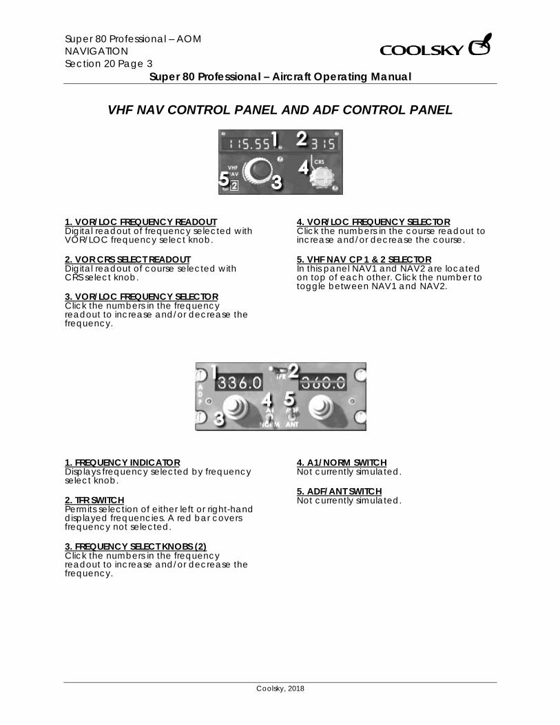
Super 80 Professional – AOM NAVIGATION Section 20 Page 3
Super 80 Professional – Aircraft Operating Manual
Coolsky, 2018
VHF NAV CONTROL PANEL AND ADF CONTROL PANEL
1. VOR/LOC FREQUENCY READOUT Digital readout of frequency selected with VOR/LOC frequency select knob. 2. VOR CRS SELECT READOUT Digital readout of course selected with CRS select knob. 3. VOR/LOC FREQUENCY SELECTOR Click the numbers in the frequency readout to increase and/or decrease the frequency.
4. VOR/LOC FREQUENCY SELECTOR Click the numbers in the course readout to increase and/or decrease the course. 5. VHF NAV CP 1 & 2 SELECTOR In this panel NAV1 and NAV2 are located on top of each other. Click the number to toggle between NAV1 and NAV2.
1. FREQUENCY INDICATOR Displays frequency selected by frequency select knob. 2. TFR SWITCH Permits selection of either left or right-hand displayed frequencies. A red bar covers frequency not selected. 3. FREQUENCY SELECT KNOBS (2) Click the numbers in the frequency readout to increase and/or decrease the frequency.
4. A1/NORM SWITCH Not currently simulated. 5. ADF/ANT SWITCH Not currently simulated.

Super 80 Professional – AOM NAVIGATION Section 20 Page 4
Super 80 Professional – Aircraft Operating Manual
Coolsky, 2018
RADIO DISTANCE MAGNETIC INDICATOR (RDMI)
1. DME 1/2 INDICATORS Displays slant range distance to the selected station on NAV 1/2 in nautical miles. 2. VOR/ADF 1 POINTER Indicates bearing to VOR or ADF station as selected on the VHF NAV radio or ADF control panel. VOR/ADF function is selected with the VOR/ADF 1 selector knob. 3. VOR/ADF 2 POINTER Indicates bearing to VOR or ADF station as selected on the VHF NAV radio or ADF control panel. VOR/ADF function is selected with the VOR/ADF 2 selector knob. 4. VOR/ADF 1 SELECTOR KNOB VOR VOR/ADF 1 pointer displays
bearing to the VOR station selected on the VHF NAV radio.
ADF VOR/ADF 1 pointer displays bearing to the ADF facility selected on the ADF control panel.
5. VOR/ADF 2 SELECTOR KNOB VOR VOR/ADF 2 pointer displays
bearing to the VOR station selected on the VHF NAV radio.
ADF VOR/ADF 2 pointer displays bearing to the ADF facility selected on the ADF control panel.
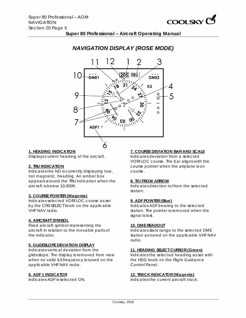
Super 80 Professional – AOM NAVIGATION Section 20 Page 5
Super 80 Professional – Aircraft Operating Manual
Coolsky, 2018
NAVIGATION DISPLAY (ROSE MODE)
1. HEADING INDICATION Displays current heading of the aircraft. 2. TRU INDICATION Indicates the ND is currently displaying true, not magnetic, heading. An amber box appears around the TRU indication when the aircraft is below 10,000ft. 3. COURSE POINTER (Magenta) Indicates selected VOR/LOC course as set by the CRS SELECT knob on the applicable VHF NAV radio. 4. AIRCRAFT SYMBOL Fixed aircraft symbol representing the aircraft in relation to the movable parts of the indicator. 5. GLIDESLOPE DEVIATION DISPLAY Indicates vertical deviation from the glideslope. The display is removed from view when no valid ILS frequency is tuned on the applicable VHF NAV radio. 6. ADF 1 INDICATOR Indicates ADF is selected ON.
7. COURSE DEVIATION BAR AND SCALE Indicates deviation from a selected VOR/LOC course. The bar aligns with the course pointer when the airplane is on course. 8. TO/FROM ARROW Indicates direction to/from the selected station. 9. ADF POINTER (Blue) Indicates ADF bearing to the selected station. The pointer is removed when the signal is lost. 10. DME READOUT Indicates slant range to the selected DME station as tuned on the applicable VHF NAV radio. 11. HEADING SELECT CURSOR (Green) Indicates the selected heading as set with the HDG knob on the Flight Guidance Control Panel. 12. TRACK INDICATOR (Magenta) Indicates the current aircraft track.
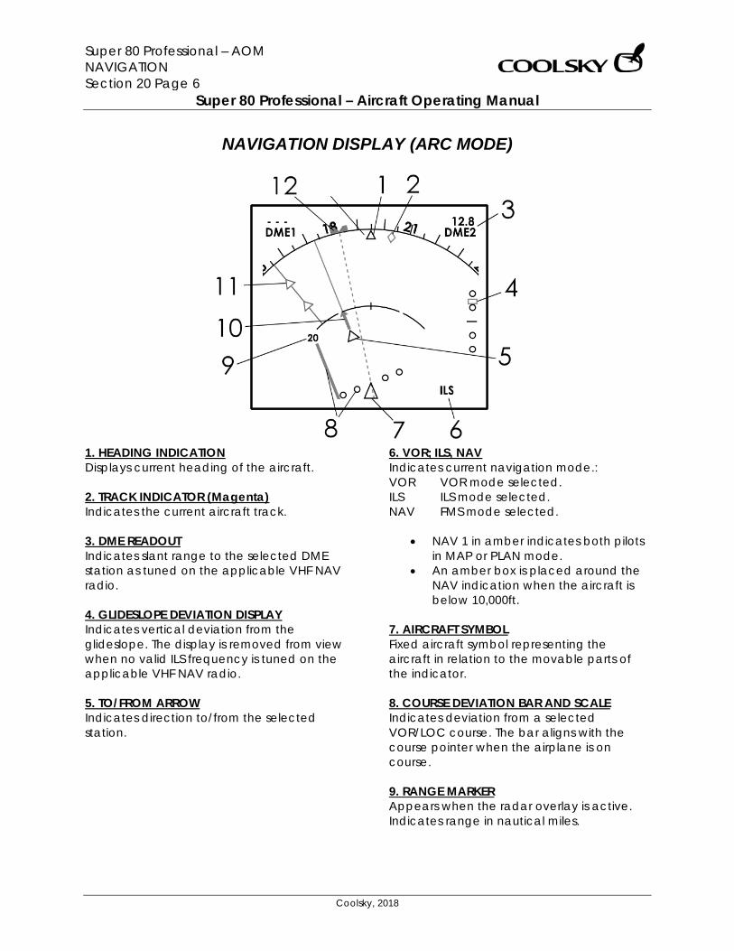
Super 80 Professional – AOM NAVIGATION Section 20 Page 6
Super 80 Professional – Aircraft Operating Manual
Coolsky, 2018
NAVIGATION DISPLAY (ARC MODE)
1. HEADING INDICATION Displays current heading of the aircraft. 2. TRACK INDICATOR (Magenta) Indicates the current aircraft track. 3. DME READOUT Indicates slant range to the selected DME station as tuned on the applicable VHF NAV radio. 4. GLIDESLOPE DEVIATION DISPLAY Indicates vertical deviation from the glideslope. The display is removed from view when no valid ILS frequency is tuned on the applicable VHF NAV radio. 5. TO/FROM ARROW Indicates direction to/from the selected station.
6. VOR; ILS, NAV Indicates current navigation mode.: VOR VOR mode selected. ILS ILS mode selected. NAV FMS mode selected.
• NAV 1 in amber indicates both pilots in MAP or PLAN mode.
• An amber box is placed around the NAV indication when the aircraft is below 10,000ft.
7. AIRCRAFT SYMBOL Fixed aircraft symbol representing the aircraft in relation to the movable parts of the indicator. 8. COURSE DEVIATION BAR AND SCALE Indicates deviation from a selected VOR/LOC course. The bar aligns with the course pointer when the airplane is on course. 9. RANGE MARKER Appears when the radar overlay is active. Indicates range in nautical miles.

Super 80 Professional – AOM NAVIGATION Section 20 Page 7
Super 80 Professional – Aircraft Operating Manual
Coolsky, 2018
10. COURSE POINTER (Magenta) Indicates selected VOR/LOC course as set by the CRS SELECT knob on the applicable VHF NAV radio. 11. ADF POINTER (Blue) Indicates ADF bearing to the selected station. The pointer is removed when the signal is lost. 12. HEADING SELECT CURSOR (Green) Indicates the selected heading as set with the HDG knob on the Flight Guidance Control Panel.
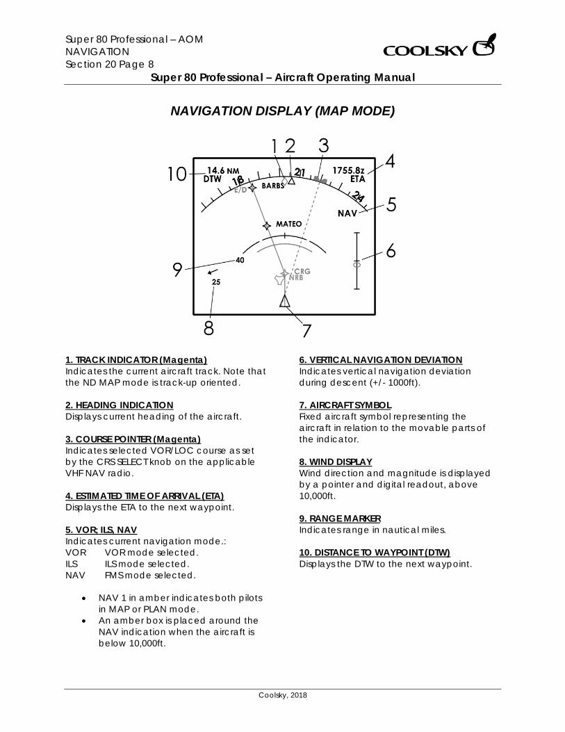
Super 80 Professional – AOM NAVIGATION Section 20 Page 8
Super 80 Professional – Aircraft Operating Manual
Coolsky, 2018
NAVIGATION DISPLAY (MAP MODE)
1. TRACK INDICATOR (Magenta) Indicates the current aircraft track. Note that the ND MAP mode is track-up oriented. 2. HEADING INDICATION Displays current heading of the aircraft. 3. COURSE POINTER (Magenta) Indicates selected VOR/LOC course as set by the CRS SELECT knob on the applicable VHF NAV radio. 4. ESTIMATED TIME OF ARRIVAL (ETA) Displays the ETA to the next waypoint. 5. VOR; ILS, NAV Indicates current navigation mode.: VOR VOR mode selected. ILS ILS mode selected. NAV FMS mode selected.
• NAV 1 in amber indicates both pilots in MAP or PLAN mode.
• An amber box is placed around the NAV indication when the aircraft is below 10,000ft.
6. VERTICAL NAVIGATION DEVIATION Indicates vertical navigation deviation during descent (+/- 1000ft). 7. AIRCRAFT SYMBOL Fixed aircraft symbol representing the aircraft in relation to the movable parts of the indicator. 8. WIND DISPLAY Wind direction and magnitude is displayed by a pointer and digital readout, above 10,000ft. 9. RANGE MARKER Indicates range in nautical miles. 10. DISTANCE TO WAYPOINT (DTW) Displays the DTW to the next waypoint.
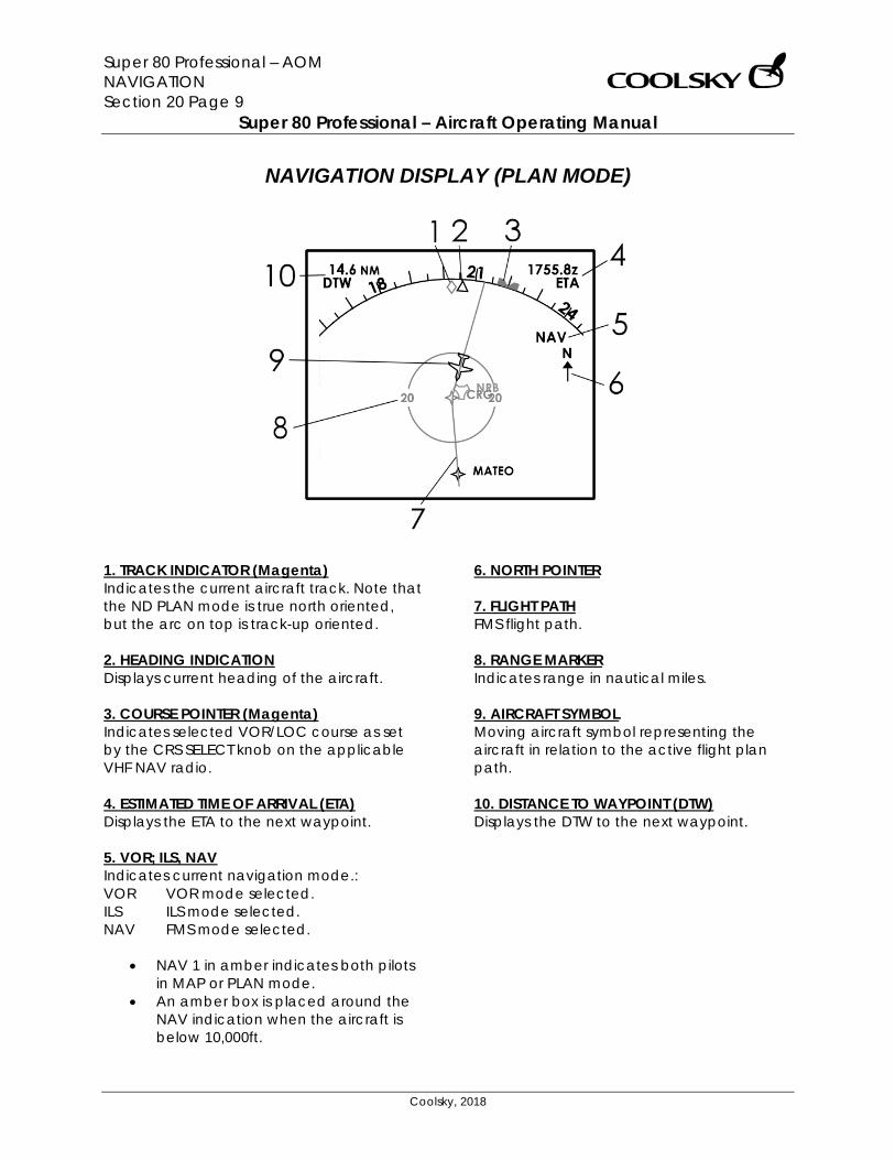
Super 80 Professional – AOM NAVIGATION Section 20 Page 9
Super 80 Professional – Aircraft Operating Manual
Coolsky, 2018
NAVIGATION DISPLAY (PLAN MODE)
1. TRACK INDICATOR (Magenta) Indicates the current aircraft track. Note that the ND PLAN mode is true north oriented, but the arc on top is track-up oriented. 2. HEADING INDICATION Displays current heading of the aircraft. 3. COURSE POINTER (Magenta) Indicates selected VOR/LOC course as set by the CRS SELECT knob on the applicable VHF NAV radio. 4. ESTIMATED TIME OF ARRIVAL (ETA) Displays the ETA to the next waypoint. 5. VOR; ILS, NAV Indicates current navigation mode.: VOR VOR mode selected. ILS ILS mode selected. NAV FMS mode selected.
• NAV 1 in amber indicates both pilots in MAP or PLAN mode.
• An amber box is placed around the NAV indication when the aircraft is below 10,000ft.
6. NORTH POINTER 7. FLIGHT PATH FMS flight path. 8. RANGE MARKER Indicates range in nautical miles. 9. AIRCRAFT SYMBOL Moving aircraft symbol representing the aircraft in relation to the active flight plan path. 10. DISTANCE TO WAYPOINT (DTW) Displays the DTW to the next waypoint.
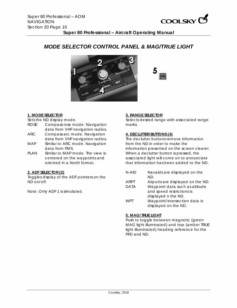
Super 80 Professional – AOM NAVIGATION Section 20 Page 10
Super 80 Professional – Aircraft Operating Manual
Coolsky, 2018
MODE SELECTOR CONTROL PANEL & MAG/TRUE LIGHT
1. MODE SELECTOR Sets the ND display mode. ROSE Compass rose mode. Navigation
data from VHF navigation radios. ARC Compass arc mode. Navigation
data from VHF navigation radios. MAP Similar to ARC mode. Navigation
data from FMS. PLAN Similar to MAP mode. The view is
centered on the waypoints and oriented in a North format.
2. ADF SELECTOR (2) Toggles display of the ADF pointers on the ND on/off. Note: Only ADF 1 is simulated.
3. RANGE SELECTOR Selects desired range with associated range marks. 4. DECLUTTER BUTTONS (4) The declutter buttons remove information from the ND in order to make the information presented on the screen clearer. When a declutter button is pressed, the associated light will come on to annunciate that information has been added to the ND. N-AID Navaids are displayed on the
ND. ARPT Airports are displayed on the ND. DATA Waypoint data such as altitude
and speed restrictions is displayed n the ND.
WPT Waypoint/intersection data is displayed on the ND.
5. MAG/TRUE LIGHT Push to toggle between magnetic (green MAG light illuminated) and true (amber TRUE light illuminated) heading reference for the PFD and ND.
Super 80 Professional – AOM OXYGEN Section 21 Page 0
Super 80 Professional – Aircraft Operating Manual
Coolsky, 2018
SECTION 21
OXYGEN

Super 80 Professional – AOM OXYGEN Section 21 Page 1
Super 80 Professional – Aircraft Operating Manual
Coolsky, 2018
TABLE OF CONTENTS
SECTION 21: OXYGEN 0
TABLE OF CONTENTS ................................................................................................................. 1 GENERAL .................................................................................................................................... 2 CONTROLS AND INDICATORS ................................................................................................. 3
Super 80 Professional – AOM OXYGEN Section 21 Page 2
Super 80 Professional – Aircraft Operating Manual
Coolsky, 2018
GENERAL General The aircraft is equipped with two independent oxygen systems. One oxygen system is installed in the cockpit for the Flight Crew, and the other oxygen system is installed in the passenger compartment for the passengers and Flight Attendants. Flight Crew Oxygen System Oxygen to the Flight Crew is supplied from a high-pressure gaseous oxygen supply cylinder. For normal operation of the system the supply toggle switch must be set to ON, the diluter control switch to NORMAL OXYGEN and the TEST MASK/NORMAL/EMERGENCY switch to NORMAL. This setup will supply oxygen to the masks upon demand. In the event of a cabin decompression at altitudes above 28,000 feet, the system will automatically sense the change in cabin pressure and supply the masks with 100% pure oxygen. In the event of an emergency where protective breathing is required (such as smoke in the cabin, etc.) the diluter control switch must be set to the 100% OXYGEN position. If a oxygen regulator failure occurs, the diluter control switch must be set to 100% OXYGEN and the TEST MASK/NORMAL/EMERGENCY switch must be set to EMERGENCY. (The TEST MASK/NORMAL/EMERGENCY switch is currently not simulated)
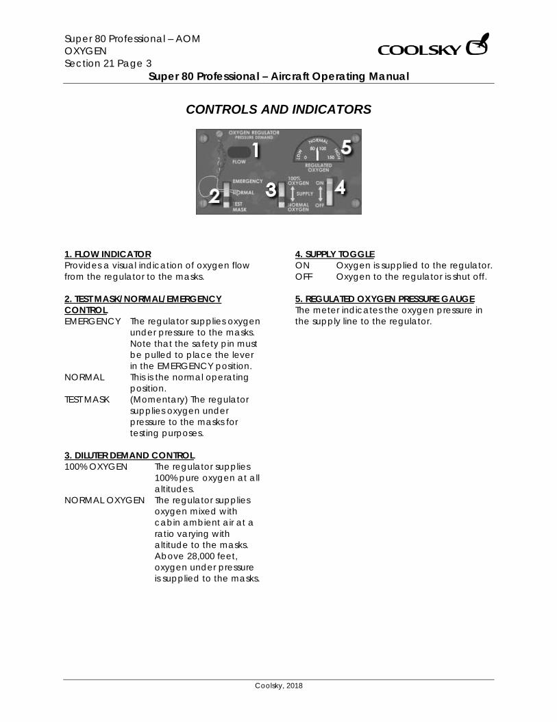
Super 80 Professional – AOM OXYGEN Section 21 Page 3
Super 80 Professional – Aircraft Operating Manual
Coolsky, 2018
CONTROLS AND INDICATORS
1. FLOW INDICATOR Provides a visual indication of oxygen flow from the regulator to the masks. 2. TEST MASK/NORMAL/EMERGENCY CONTROL EMERGENCY The regulator supplies oxygen
under pressure to the masks. Note that the safety pin must be pulled to place the lever in the EMERGENCY position.
NORMAL This is the normal operating position.
TEST MASK (Momentary) The regulator supplies oxygen under pressure to the masks for testing purposes.
3. DILUTER DEMAND CONTROL 100% OXYGEN The regulator supplies
100% pure oxygen at all altitudes.
NORMAL OXYGEN The regulator supplies oxygen mixed with cabin ambient air at a ratio varying with altitude to the masks. Above 28,000 feet, oxygen under pressure is supplied to the masks.
4. SUPPLY TOGGLE ON Oxygen is supplied to the regulator. OFF Oxygen to the regulator is shut off. 5. REGULATED OXYGEN PRESSURE GAUGE The meter indicates the oxygen pressure in the supply line to the regulator.

Super 80 Professional – AOM POWER PLANT Section 22 Page 0
Super 80 Professional – Aircraft Operating Manual
Coolsky, 2018
SECTION 22
POWER PLANT

Super 80 Professional – AOM POWER PLANT Section 22 Page 1
Super 80 Professional – Aircraft Operating Manual
Coolsky, 2018
TABLE OF CONTENTS
SECTION 22: POWER PLANT 0
TABLE OF CONTENTS ................................................................................................................. 1 GENERAL .................................................................................................................................... 2 CONTROLS AND INDICATORS ................................................................................................. 5 WARNING AND CAUTION INDICATORS ............................................................................... 11
Super 80 Professional – AOM POWER PLANT Section 22 Page 2
Super 80 Professional – Aircraft Operating Manual
Coolsky, 2018
GENERAL The airplane is equipped with two axial-flow, bypass, turbofan, Pratt and Whitney JT8D engines, which have a normal static take-off thrust rating of 20,000 pounds and a maximum take-off thrust rating of 20,850 pounds. The JT8D axial flow turbofan engine utilizes a 14-stage split compressor, a 4-stage split turbine, a 9-can combustion chamber, two integral accessory drive cases, and a full length integral fan annular discharge duct. An automatic reserve thrust (ART) system is installed. In the event of an engine failure, the ART system increases the thrust on the remaining engine (not simulated). Engine Starting Either engine may be started by using a pneumatic ground supply or by pneumatic supply from the auxiliary power unit. When one engine is operating, the opposite engine may be started by using the pneumatic crossfeed system. An electrically controlled, pneumatically actuated starter air shutoff valve on each engine controls the starter of the respective engine. Ignition Systems Two ignition systems, one 20-Joule (high energy ignition system) and one four-Joule (low energy ignition system), are provided for each engine. An IGN (ignition) switch is provided on the ENG panel for ignition system selection.
IGN switch position: OVRD High energy ignition is supplied to
both igniters on both engines, regardless of fuel lever and engine starter positions.
CONTIN Low energy ignition is supplied to a single igniter on the engine, depending on fuel lever position.
With the engine starter switches in GND or FLT, high energy ignition is supplied to both igniters on the engine, depending on fuel lever position. Engine Oil System Oil is pumped from the oil tank by the main oil pump and delivered to the system through an oil filter. Oil quantity is sensed in the oil tank and displayed on the System Display Panel. Engine Fuel System Fuel, from the fuel supply system, passes through the engine driven first stage centrifugal pump. From the pump, the fuel flows through the air/fuel heat exchanger. The fuel is then filtered before entering the fuel control valve. The fuel may bypass the filter if it becomes clogged. A fuel flow transmitter measures fuel delivered from the fuel control to the engine.
Super 80 Professional – AOM POWER PLANT Section 22 Page 3
Super 80 Professional – Aircraft Operating Manual
Coolsky, 2018
Thrust Reversers Two thrust reverser doors (each engine) provide the means for directing fan air and exhaust gases. The thrust reverser direct flow for reverse engine thrust, to achieve aircraft ground deceleration. When the thrust reverser unlatches, an amber ENG REVERSE UNLOCK light on the center instrument panel comes on. When the reverser is fully extended, a blue ENG REVERSE THRUST light on the center instrument panel comes on. Engine Synchronizer System The engine synchronizer system automatically matches the N1 or N2 RPM speed of both engines provided the N1’s or N2’s (as selected) are within 1% of each other when the synchronizer is turned on. An ENG SYNC ON annunciator light on the overhead panel will come on when the landing gear handle is in the down position and the ENG SYNC selector is in the N1 or N2 position. Note: The ENG SYNC switch must be OFF during takeoff, landing, thrust reverse operation, or when the airplane is below 1500ft AGL. Automatic Reserve Thrust (ART). The ART system provides for the automatic detection of an engine failure during takeoff and a subsequent thrust increase on the operating engine. The ART system consists of a two position switch and three annunciator lights. A green ready light comes on when the ART self test has been completed. The amber ART light comes on when the system has detected an
engine failure (one N1 30% less than the other N1). When ART has been activated:
• Fuel control is adjusted to a thrust schedule resulting in an 850 pound increase in thrust.
• Operating engine instruments display an increase in N1, N2, EPR and fuel flow.
• EPR LIM readout will display a computed reserve thrust EPR LIM.
• EPR reference bug will be set according to computed reserve thrust EPR LIM.
An amber ART INOP light on the overhead annunciator panel indicates a failure in the ART system, or the ART switch is in the OFF position. System operation is fully automatic with the ART switch in the AUTO position. Self test will be initiated with the airplane on the ground, both engines running and slats extended. With the green READY light on, the ART system is armed when power on both engines is advanced beyond 64% N1. After takeoff, the ART system is disarmed when slats are retracted. However, the ART system will also disarm if both engines are retarded to below 58% N1. When disarmed by slat retraction, the system can only be rearmed with the airplane on the ground. When disarmed by power reduction, the READY light will come on, and the system will rearm when power on both engines is advanced beyond 64% N1.

Super 80 Professional – AOM POWER PLANT Section 22 Page 4
Super 80 Professional – Aircraft Operating Manual
Coolsky, 2018
Approach Idle Five seconds after the nose gear indicates down and locked, the engines shift from normal idle to approach idle. Approach idle RPM is approximately 10% higher than normal idle RPM. During landing, five seconds after nose strut compression, the engines shift back to normal idle. Approach idle is currently not simulated in this panel.
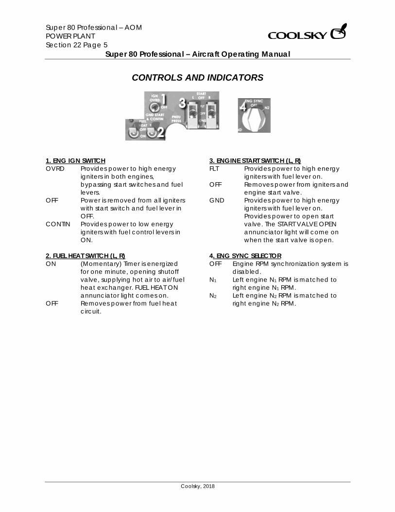
Super 80 Professional – AOM POWER PLANT Section 22 Page 5
Super 80 Professional – Aircraft Operating Manual
Coolsky, 2018
CONTROLS AND INDICATORS
1. ENG IGN SWITCH OVRD Provides power to high energy
igniters in both engines, bypassing start switches and fuel levers.
OFF Power is removed from all igniters with start switch and fuel lever in OFF.
CONTIN Provides power to low energy igniters with fuel control levers in ON.
2. FUEL HEAT SWITCH (L, R) ON (Momentary) Timer is energized
for one minute, opening shutoff valve, supplying hot air to air/fuel heat exchanger. FUEL HEAT ON annunciator light comes on.
OFF Removes power from fuel heat circuit.
3. ENGINE START SWITCH (L, R) FLT Provides power to high energy
igniters with fuel lever on. OFF Removes power from igniters and
engine start valve. GND Provides power to high energy
igniters with fuel lever on. Provides power to open start valve. The START VALVE OPEN annunciator light will come on when the start valve is open.
4. ENG SYNC SELECTOR OFF Engine RPM synchronization system is
disabled. N1 Left engine N1 RPM is matched to
right engine N1 RPM. N2 Left engine N2 RPM is matched to
right engine N2 RPM.
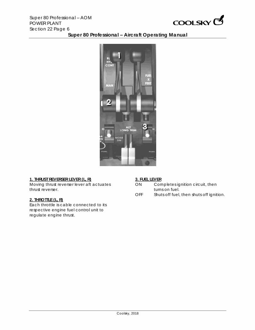
Super 80 Professional – AOM POWER PLANT Section 22 Page 6
Super 80 Professional – Aircraft Operating Manual
Coolsky, 2018
1. THRUST REVERSER LEVER (L, R) Moving thrust reverser lever aft actuates thrust reverser. 2. THROTTLE (L, R) Each throttle is cable connected to its respective engine fuel control unit to regulate engine thrust.
3. FUEL LEVER ON Completes ignition circuit, then
turns on fuel. OFF Shuts off fuel, then shuts off ignition.
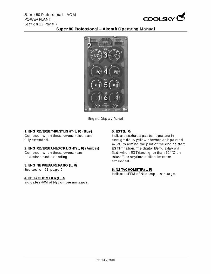
Super 80 Professional – AOM POWER PLANT Section 22 Page 7
Super 80 Professional – Aircraft Operating Manual
Coolsky, 2018
Engine Display Panel
1. ENG REVERSE THRUST LIGHT (L, R) (Blue) Comes on when thrust reverser doors are fully extended. 2. ENG REVERSE UNLOCK LIGHT (L, R) (Amber) Comes on when thrust reverser are unlatched and extending. 3. ENGINE PRESSURE RATIO (L, R) See section 21, page 9. 4. N1 TACHOMETER (L, R) Indicates RPM of N1 compressor stage.
5. EGT (L, R) Indicates exhaust gas temperature in centigrade. A yellow chevron at is painted 475°C to remind the pilot of the engine start EGT limitation. The digital EGT display will flash when EGT rises higher than 624°C on takeoff, or anytime redline limits are exceeded. 6. N2 TACHOMETER (L, R) Indicates RPM of N2 compressor stage.
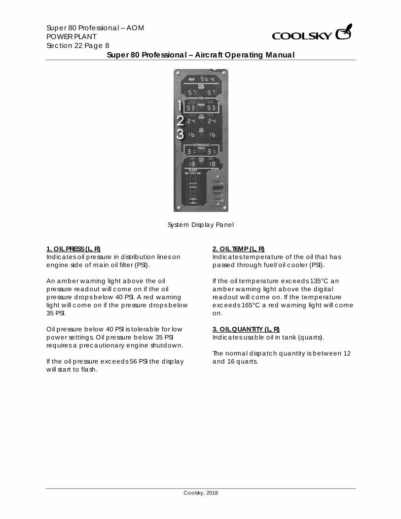
Super 80 Professional – AOM POWER PLANT Section 22 Page 8
Super 80 Professional – Aircraft Operating Manual
Coolsky, 2018
System Display Panel 1. OIL PRESS (L, R) Indicates oil pressure in distribution lines on engine side of main oil filter (PSI). An amber warning light above the oil pressure readout will come on if the oil pressure drops below 40 PSI. A red warning light will come on if the pressure drops below 35 PSI. Oil pressure below 40 PSI is tolerable for low power settings. Oil pressure below 35 PSI requires a precautionary engine shutdown. If the oil pressure exceeds 56 PSI the display will start to flash.
2. OIL TEMP (L, R) Indicates temperature of the oil that has passed through fuel/oil cooler (PSI). If the oil temperature exceeds 135°C an amber warning light above the digital readout will come on. If the temperature exceeds 165°C a red warning light will come on. 3. OIL QUANTITY (L, R) Indicates usable oil in tank (quarts). The normal dispatch quantity is between 12 and 16 quarts.
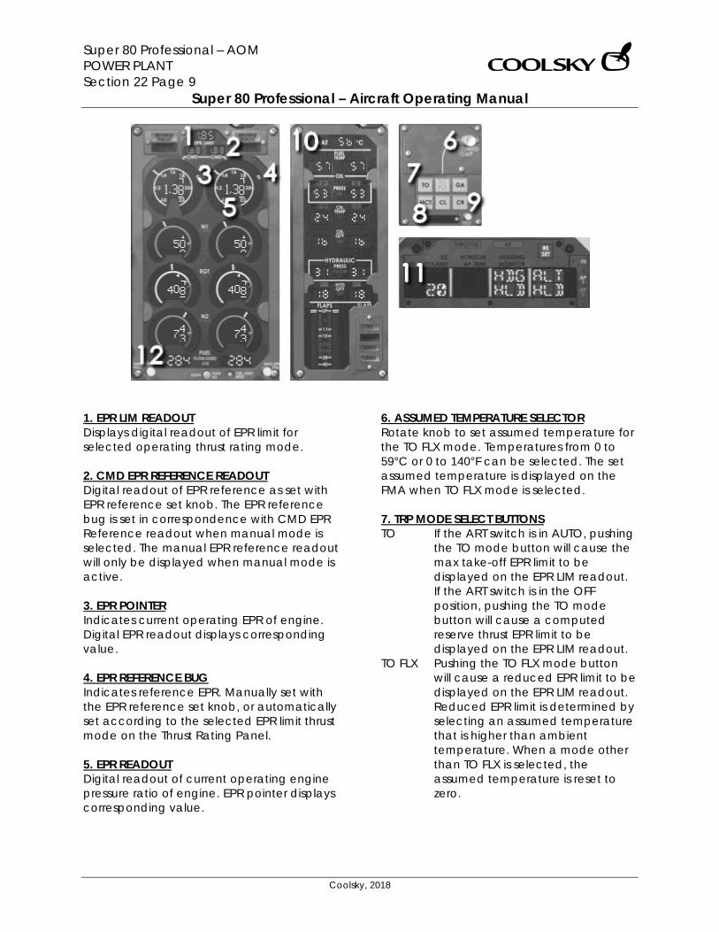
Super 80 Professional – AOM POWER PLANT Section 22 Page 9
Super 80 Professional – Aircraft Operating Manual
Coolsky, 2018
1. EPR LIM READOUT Displays digital readout of EPR limit for selected operating thrust rating mode. 2. CMD EPR REFERENCE READOUT Digital readout of EPR reference as set with EPR reference set knob. The EPR reference bug is set in correspondence with CMD EPR Reference readout when manual mode is selected. The manual EPR reference readout will only be displayed when manual mode is active. 3. EPR POINTER Indicates current operating EPR of engine. Digital EPR readout displays corresponding value. 4. EPR REFERENCE BUG Indicates reference EPR. Manually set with the EPR reference set knob, or automatically set according to the selected EPR limit thrust mode on the Thrust Rating Panel. 5. EPR READOUT Digital readout of current operating engine pressure ratio of engine. EPR pointer displays corresponding value.
6. ASSUMED TEMPERATURE SELECTOR Rotate knob to set assumed temperature for the TO FLX mode. Temperatures from 0 to 59°C or 0 to 140°F can be selected. The set assumed temperature is displayed on the FMA when TO FLX mode is selected. 7. TRP MODE SELECT BUTTONS TO If the ART switch is in AUTO, pushing
the TO mode button will cause the max take-off EPR limit to be displayed on the EPR LIM readout. If the ART switch is in the OFF position, pushing the TO mode button will cause a computed reserve thrust EPR limit to be displayed on the EPR LIM readout.
TO FLX Pushing the TO FLX mode button will cause a reduced EPR limit to be displayed on the EPR LIM readout. Reduced EPR limit is determined by selecting an assumed temperature that is higher than ambient temperature. When a mode other than TO FLX is selected, the assumed temperature is reset to zero.
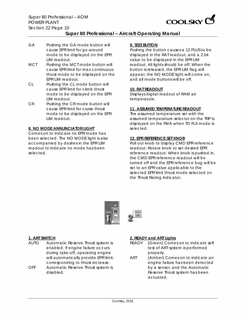
Super 80 Professional – AOM POWER PLANT Section 22 Page 10
Super 80 Professional – Aircraft Operating Manual
Coolsky, 2018
GA Pushing the GA mode button will cause EPR limit for go-around mode to be displayed on the EPR LIM readout.
MCT Pushing the MCT mode button will cause EPR limit for max continuous thrust mode to be displayed on the EPR LIM readout.
CL Pushing the CL mode button will cause EPR limit for climb thrust mode to be displayed on the EPR LIM readout.
CR Pushing the CR mode button will cause EPR limit for cruise thrust mode to be displayed on the EPR LIM readout.
8. NO MODE ANNUNCIATOR LIGHT Comes on to indicate no EPR mode has been selected. The NO MODE light is also accompanied by dashes in the EPR LIM readout to indicate no mode has been selected.
9. TEST BUTTON Pushing the button causes a 12 PLUS to be displayed in the RAT readout, and a 2.04 value to be displayed in the EPR LIM readout. All lights should be off. When the button is released, the EPR LIM flag will appear, the NO MODE light will come on, and all mode buttons will be off. 10. RAT READOUT Displays digital readout of RAM air temperature. 11. ASSUMED TEMPERATURE READOUT The assumed temperature set with the assumed temperature selector on the TRP is displayed on the FMA when TO FLX mode is selected. 12. EPR REFERENCE SET KNOB Pull out knob to display CMD EPR reference readout. Rotate knob to set desired EPR reference readout. When knob is pushed in, the CMD EPR reference readout will be turned off and the EPR reference bug will be set to an EPR value applicable to the selected EPR limit thrust mode selected on the Thrust Rating Indicator.
1. ART SWITCH AUTO Automatic Reserve Thrust system is
enabled. If engine failure occurs during take-off, operating engine will automatically provide EPR limit, corresponding to thrust increase.
OFF Automatic Reserve Thrust system is disabled.
2. READY and ART Lights READY (Green) Comes on to indicate self
test of ART system is performed properly.
ART (Amber) Comes on to indicate an engine failure has been detected by a sensor, and the Automatic Reserve Thrust system has been actuated.
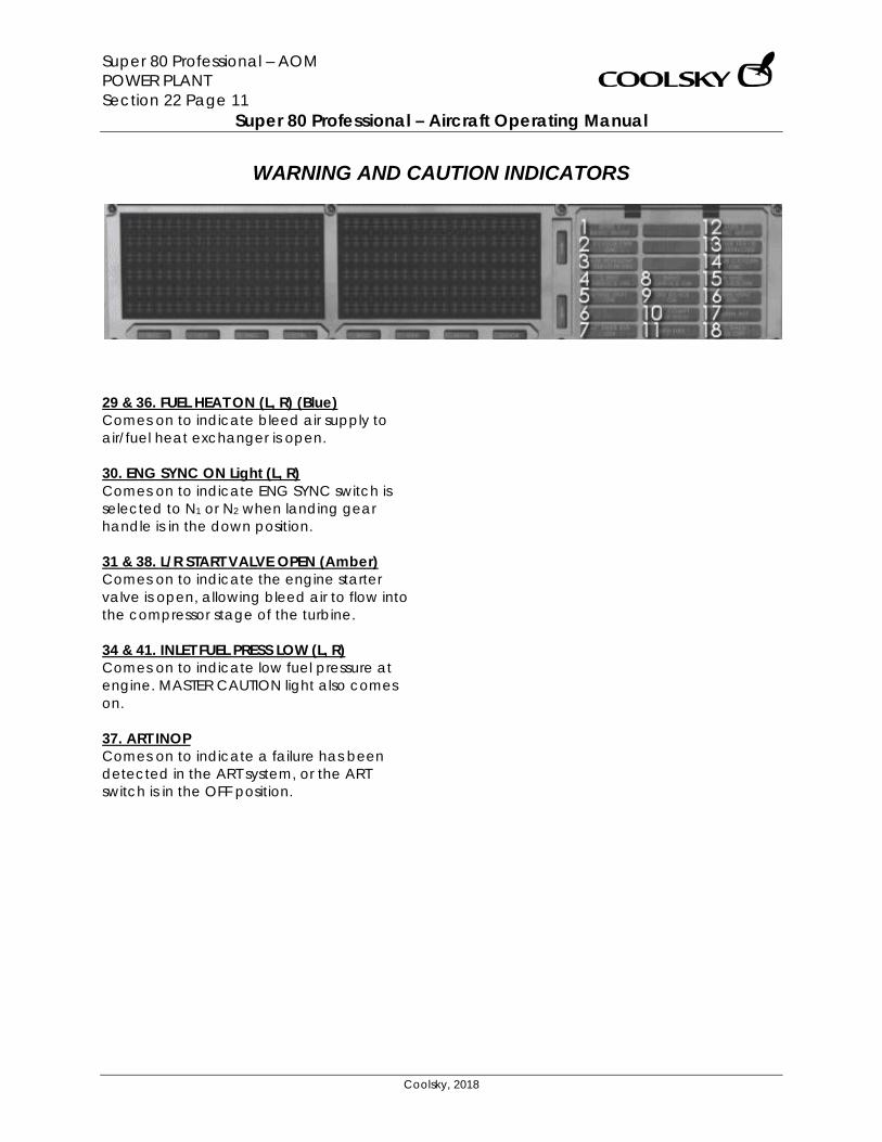
Super 80 Professional – AOM POWER PLANT Section 22 Page 11
Super 80 Professional – Aircraft Operating Manual
Coolsky, 2018
WARNING AND CAUTION INDICATORS
29 & 36. FUEL HEAT ON (L, R) (Blue) Comes on to indicate bleed air supply to air/fuel heat exchanger is open. 30. ENG SYNC ON Light (L, R) Comes on to indicate ENG SYNC switch is selected to N1 or N2 when landing gear handle is in the down position. 31 & 38. L/R START VALVE OPEN (Amber) Comes on to indicate the engine starter valve is open, allowing bleed air to flow into the compressor stage of the turbine. 34 & 41. INLET FUEL PRESS LOW (L, R) Comes on to indicate low fuel pressure at engine. MASTER CAUTION light also comes on. 37. ART INOP Comes on to indicate a failure has been detected in the ART system, or the ART switch is in the OFF position.
Super 80 Professional – AOM PERFORMANCE Section 23 Page 0
Super 80 Professional – Aircraft Operating Manual
Coolsky, 2018
SECTION 23
PERFORMANCE
Super 80 Professional – AOM PERFORMANCE Section 23 Page 1
Super 80 Professional – Aircraft Operating Manual
Coolsky, 2018
TABLE OF CONTENTS
SECTION 23: PERFORMANCE 0
TABLE OF CONTENTS ................................................................................................................. 1 GENERAL .................................................................................................................................... 2 TAKE-OFF .................................................................................................................................... 4
TAKE-OFF STABILIZER SETTINGS .......................................................................................... 4 RESERVE TAKE-OFF EPR ...................................................................................................... 5 RESERVE TAKE-OFF N1 ........................................................................................................ 5 MAX TAKE-OFF EPR ............................................................................................................ 6 MAX TAKE-OFF N1 .............................................................................................................. 6 V1 – VR – V2 – DEPARTURE SPEEDS - FLAPS 4 AND 11 ...................................................... 7 V1 – VR – V2 – DEPARTURE SPEEDS - FLAPS 17 AND 24 .................................................... 8 MINIMUM V1/VMCG ............................................................................................................. 9 MINIMUM VR ....................................................................................................................... 9 MINIMUM V2 ....................................................................................................................... 9
CLIMB ........................................................................................................................................ 10 MAX CLIMB EPR ............................................................................................................... 10 MAX CONTINUOUS EPR ................................................................................................... 11
CRUISE ....................................................................................................................................... 12 MAX CRUISE EPR .............................................................................................................. 12 320 KNOT CRUISE ............................................................................................................. 13 MACH .76 CRUISE ............................................................................................................ 14 MACH .77 CRUISE ............................................................................................................ 15 MACH .78 CRUISE ............................................................................................................ 16 MACH .80 CRUISE ............................................................................................................ 17 2 ENGINES LONG RANGE CRUISE .................................................................................. 18 CRUISE MACH/280 KIAS DESCENT .................................................................................. 19 HOLDING SPEEDS AND FUEL FLOW ................................................................................ 20
ARRIVAL .................................................................................................................................... 21 MINIMUM CONTROL SPEEDS – VMCA .............................................................................. 21 STALL SPEEDS .................................................................................................................... 21 GO-AROUND EPR ............................................................................................................ 22 GO-AROUND N1 ............................................................................................................... 22 NORMAL FLAPS/SLAT CONFIGURATION ........................................................................ 23 MINIMUM MANEUVERING AND REFERENCE SPEEDS .................................................... 23 STOPPING DISTANCE WITH AUTOMATIC BRAKE SYSTEM .............................................. 24 TOUCHDOWN TO FULL STOP........................................................................................... 24
MISCELLANEOUS ..................................................................................................................... 25 ENROUTE CLIMB ............................................................................................................... 25
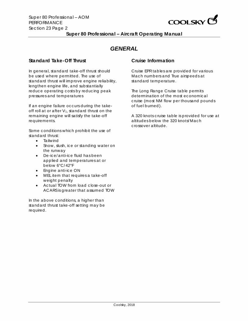
Super 80 Professional – AOM PERFORMANCE Section 23 Page 2
Super 80 Professional – Aircraft Operating Manual
Coolsky, 2018
GENERAL Standard Take-Off Thrust In general, standard take-off thrust should be used where permitted. The use of standard thrust will improve engine reliability, lengthen engine life, and substantially reduce operating costs by reducing peak pressures and temperatures If an engine failure occurs during the take-off roll at or after V1, standard thrust on the remaining engine will satisfy the take-off requirements. Some conditions which prohibit the use of standard thrust:
• Tailwind • Snow, slush, ice or standing water on
the runway • De-ice/anti-ice fluid has been
applied and temperatures at or below 6°C/42°F
• Engine anti-ice ON • MEL item that requires a take-off
weight penalty • Actual TOW from load close-out or
ACARS is greater that assumed TOW In the above conditions, a higher than standard thrust take-off setting may be required.
Cruise Information Cruise EPR tables are provided for various Mach numbers and True airspeeds at standard temperature. The Long Range Cruise table permits determination of the most economical cruise (most NM flow per thousand pounds of fuel burned). A 320 knots cruise table is provided for use at altitudes below the 320 knots/Mach crossover altitude.
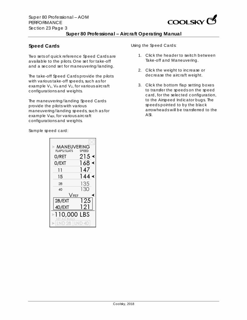
Super 80 Professional – AOM PERFORMANCE Section 23 Page 3
Super 80 Professional – Aircraft Operating Manual
Coolsky, 2018
Speed Cards Two sets of quick reference Speed Cards are available to the pilots. One set for take-off and a second set for maneuvering/landing. The take-off Speed Cards provide the pilots with various take-off speeds, such as for example V1, VR and V2, for various aircraft configurations and weights. The maneuvering/landing Speed Cards provide the pilots with various maneuvering/landing speeds, such as for example VREF, for various aircraft configurations and weights. Sample speed card:
Using the Speed Cards:
1. Click the header to switch between Take-off and Maneuvering.
2. Click the weight to increase or
decrease the aircraft weight. 3. Click the bottom flap setting boxes
to transfer the speeds on the speed card, for the selected configuration, to the Airspeed Indicator bugs. The speeds pointed to by the black arrowheads will be transferred to the ASI.
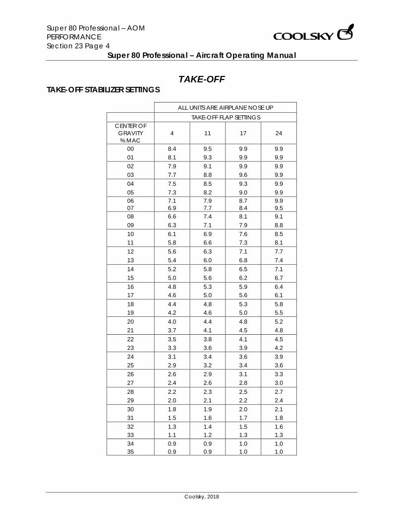
Super 80 Professional – AOM PERFORMANCE Section 23 Page 4
Super 80 Professional – Aircraft Operating Manual
Coolsky, 2018
TAKE-OFF TAKE-OFF STABILIZER SETTINGS
ALL UNITS ARE AIRPLANE NOSE UP TAKE-OFF FLAP SETTINGS
CENTER OF GRAVITY % MAC
4 11 17 24
00 8.4 9.5 9.9 9.9 01 8.1 9.3 9.9 9.9 02 7.9 9.1 9.9 9.9 03 7.7 8.8 9.6 9.9 04 7.5 8.5 9.3 9.9 05 7.3 8.2 9.0 9.9 06 7.1 7.9 8.7 9.9 07 6.9 7.7 8.4 9.5 08 6.6 7.4 8.1 9.1 09 6.3 7.1 7.9 8.8 10 6.1 6.9 7.6 8.5 11 5.8 6.6 7.3 8.1 12 5.6 6.3 7.1 7.7 13 5.4 6.0 6.8 7.4 14 5.2 5.8 6.5 7.1 15 5.0 5.6 6.2 6.7 16 4.8 5.3 5.9 6.4 17 4.6 5.0 5.6 6.1 18 4.4 4.8 5.3 5.8 19 4.2 4.6 5.0 5.5 20 4.0 4.4 4.8 5.2 21 3.7 4.1 4.5 4.8 22 3.5 3.8 4.1 4.5 23 3.3 3.6 3.9 4.2 24 3.1 3.4 3.6 3.9 25 2.9 3.2 3.4 3.6 26 2.6 2.9 3.1 3.3 27 2.4 2.6 2.8 3.0 28 2.2 2.3 2.5 2.7 29 2.0 2.1 2.2 2.4 30 1.8 1.9 2.0 2.1 31 1.5 1.6 1.7 1.8 32 1.3 1.4 1.5 1.6 33 1.1 1.2 1.3 1.3 34 0.9 0.9 1.0 1.0 35 0.9 0.9 1.0 1.0
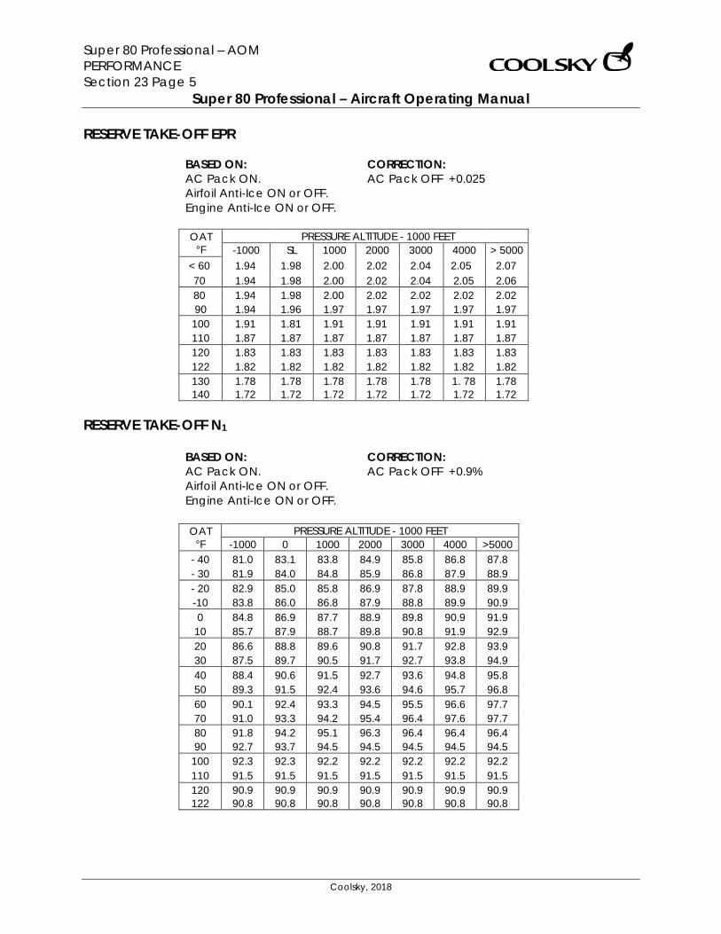
Super 80 Professional – AOM PERFORMANCE Section 23 Page 5
Super 80 Professional – Aircraft Operating Manual
Coolsky, 2018
RESERVE TAKE-OFF EPR
BASED ON: AC Pack ON. Airfoil Anti-Ice ON or OFF. Engine Anti-Ice ON or OFF.
CORRECTION: AC Pack OFF +0.025
OAT
°F PRESSURE ALTITUDE - 1000 FEET
-1000 SL 1000 2000 3000 4000 > 5000 < 60 1.94 1.98 2.00 2.02 2.04 2.05 2.07 70 1.94 1.98 2.00 2.02 2.04 2.05 2.06 80 1.94 1.98 2.00 2.02 2.02 2.02 2.02 90 1.94 1.96 1.97 1.97 1.97 1.97 1.97
100 1.91 1.81 1.91 1.91 1.91 1.91 1.91 110 1.87 1.87 1.87 1.87 1.87 1.87 1.87 120 1.83 1.83 1.83 1.83 1.83 1.83 1.83 122 1.82 1.82 1.82 1.82 1.82 1.82 1.82 130 1.78 1.78 1.78 1.78 1.78 1. 78 1.78 140 1.72 1.72 1.72 1.72 1.72 1.72 1.72
RESERVE TAKE-OFF N1
BASED ON: AC Pack ON. Airfoil Anti-Ice ON or OFF. Engine Anti-Ice ON or OFF.
CORRECTION: AC Pack OFF +0.9%
OAT
°F PRESSURE ALTITUDE - 1000 FEET
-1000 0 1000 2000 3000 4000 >5000 - 40 81.0 83.1 83.8 84.9 85.8 86.8 87.8 - 30 81.9 84.0 84.8 85.9 86.8 87.9 88.9 - 20 82.9 85.0 85.8 86.9 87.8 88.9 89.9 -10 83.8 86.0 86.8 87.9 88.8 89.9 90.9 0 84.8 86.9 87.7 88.9 89.8 90.9 91.9
10 85.7 87.9 88.7 89.8 90.8 91.9 92.9 20 86.6 88.8 89.6 90.8 91.7 92.8 93.9 30 87.5 89.7 90.5 91.7 92.7 93.8 94.9 40 88.4 90.6 91.5 92.7 93.6 94.8 95.8 50 89.3 91.5 92.4 93.6 94.6 95.7 96.8 60 90.1 92.4 93.3 94.5 95.5 96.6 97.7 70 91.0 93.3 94.2 95.4 96.4 97.6 97.7 80 91.8 94.2 95.1 96.3 96.4 96.4 96.4 90 92.7 93.7 94.5 94.5 94.5 94.5 94.5
100 92.3 92.3 92.2 92.2 92.2 92.2 92.2 110 91.5 91.5 91.5 91.5 91.5 91.5 91.5 120 90.9 90.9 90.9 90.9 90.9 90.9 90.9 122 90.8 90.8 90.8 90.8 90.8 90.8 90.8

Super 80 Professional – AOM PERFORMANCE Section 23 Page 6
Super 80 Professional – Aircraft Operating Manual
Coolsky, 2018
MAX TAKE-OFF EPR
BASED ON: AC Pack ON. Airfoil Anti-Ice ON or OFF. Engine Anti-Ice ON or OFF.
CORRECTION: AC Pack OFF +0.025
MAX TAKE-OFF N1
BASED ON: AC Pack ON. Airfoil Anti-Ice ON or OFF. Engine Anti-Ice ON or OFF.
CORRECTION: AC Pack OFF +0.9%
OAT
°F PRESSURE ALTITUDE - 1000 FEET
-1000 0 1000 2000 3000 4000 > 5000 -40 78.8 80.6 81.6 82.6 83.6 84.7 85.9 -30 79.7 81.6 82.6 83.6 84.6 85.7 86.9 -20 80.7 82.5 83.5 84.6 85.6 85.7 87.9 -10 81.6 83.5 84.5 85.5 86.5 87.7 88.9 0 82.5 8't.4 85.4 86.5 87.5 88.6 89.9
10 83.4 85.3 86.3 87.4 88.4 89.6 90.9 20 84.3 86.2 87.3 88.3 89.4 90.6 91.8 30 85.1 87.1 88.2 89.2 90.3 91. 5 92.8 40 86.0 88.0 89.1 90.1 91.2 92.4 93.7 50 86.9 88.9 89.9 91.0 92.1 93.3 94.7 60 87.7 89.7 90.8 91.9 93.0 94.3 95.6 70 88.5 90.6 91.7 92.8 93.9 95.2 95.3 80 89.4 91.4 92.6 93.7 93.8 93.8 93.8 90 90.2 90.9 91.9 91.9 91.9 91.9 91.9
100 90.3 90.3 90.3 90.3 90.3 90.3 90.3 110 89.7 89.7 89.7 89.7 89.7 89.7 89.7 120 89.1 89.1 89.1 89.1 89.1 89.1 89.1 122 89.0 89.0 89.0 89.0 89.0 89.0 89.0
OAT °F
PRESSURE ALTITUDE - 1000 FEET -1000 SL 1000 2000 3000 4000 > 5000
< 60 1.88 1.93 1.95 1.97 1.99 2.02 2.04 70 1.88 1.93 1.95 1.97 1.99 2.02 2.02 80 1.88 1.93 1.95 1.97 1.98 1.98 1.98 90 1.88 1.90 1.92 1.92 1.92 1.92 1.92
100 1.86 1.86 1.86 1.86 1.86 1.86 1.86 110 1.81 1.81 1.81 1.81 1.81 1.81 1.81 120 1.77 1.77 1.77 1.77 1.77 1.77 1.77 122 1.76 1.76 1.76 1.76 1.76 1.76 1.76
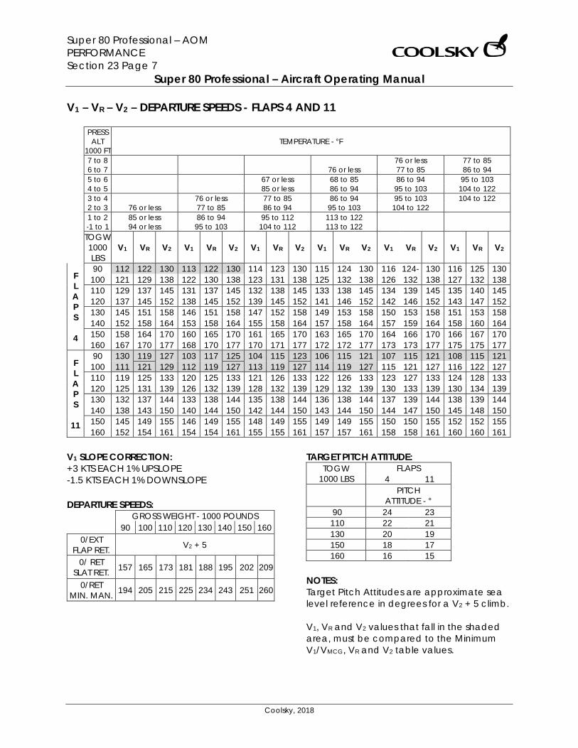
Super 80 Professional – AOM PERFORMANCE Section 23 Page 7
Super 80 Professional – Aircraft Operating Manual
Coolsky, 2018
V1 – VR – V2 – DEPARTURE SPEEDS - FLAPS 4 AND 11
PRESS ALT
1000 FT TEMPERATURE - °F
7 to 8 76 or less 77 to 85 6 to 7 76 or less 77 to 85 86 to 94 5 to 6 67 or less 68 to 85 86 to 94 95 to 103 4 to 5 85 or less 86 to 94 95 to 103 104 to 122 3 to 4 76 or less 77 to 85 86 to 94 95 to 103 104 to 122 2 to 3 76 or less 77 to 85 86 to 94 95 to 103 104 to 122 1 to 2 85 or less 86 to 94 95 to 112 113 to 122 -1 to 1 94 or less 95 to 103 104 to 112 113 to 122 TOGW 1000 LBS
V1 VR V2 V1 VR V2 V1 VR V2 V1 VR V2 V1 VR V2 V1 VR V2
F L A P S 4
90 112 122 130 113 122 130 114 123 130 115 124 130 116 124- 130 116 125 130 100 121 129 138 122 130 138 123 131 138 125 132 138 126 132 138 127 132 138 110 129 137 145 131 137 145 132 138 145 133 138 145 134 139 145 135 140 145 120 137 145 152 138 145 152 139 145 152 141 146 152 142 146 152 143 147 152 130 145 151 158 146 151 158 147 152 158 149 153 158 150 153 158 151 153 158 140 152 158 164 153 158 164 155 158 164 157 158 164 157 159 164 158 160 164 150 158 164 170 160 165 170 161 165 170 163 165 170 164 166 170 166 167 170 160 167 170 177 168 170 177 170 171 177 172 172 177 173 173 177 175 175 177
F L A P S
11
90 130 119 127 103 117 125 104 115 123 106 115 121 107 115 121 108 115 121 100 111 121 129 112 119 127 113 119 127 114 119 127 115 121 127 116 122 127 110 119 125 133 120 125 133 121 126 133 122 126 133 123 127 133 124 128 133 120 125 131 139 126 132 139 128 132 139 129 132 139 130 133 139 130 134 139 130 132 137 144 133 138 144 135 138 144 136 138 144 137 139 144 138 139 144 140 138 143 150 140 144 150 142 144 150 143 144 150 144 147 150 145 148 150 150 145 149 155 146 149 155 148 149 155 149 149 155 150 150 155 152 152 155 160 152 154 161 154 154 161 155 155 161 157 157 161 158 158 161 160 160 161
V1 SLOPE CORRECTION: +3 KTS EACH 1% UPSLOPE -1.5 KTS EACH 1% DOWNSLOPE DEPARTURE SPEEDS:
GROSS WEIGHT - 1000 POUNDS 90 100 110 120 130 140 150 160
0/EXT FLAP RET. V2 + 5
0/ RET SLAT RET. 157 165 173 181 188 195 202 209
0/RET MIN. MAN. 194 205 215 225 234 243 251 260
TARGET PITCH ATTITUDE: TOGW
1000 LBS FLAPS
4 11
PITCH ATTITUDE - °
90 24 23 110 22 21 130 20 19 150 18 17 160 16 15
NOTES: Target Pitch Attitudes are approximate sea level reference in degrees for a V2 + 5 climb. V1, VR and V2 values that fall in the shaded area, must be compared to the Minimum V1/VMCG, VR and V2 table values.
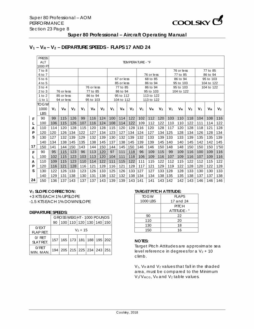
Super 80 Professional – AOM PERFORMANCE Section 23 Page 8
Super 80 Professional – Aircraft Operating Manual
Coolsky, 2018
V1 – VR – V2 – DEPARTURE SPEEDS - FLAPS 17 AND 24
PRESS ALT
1000 FT TEMPERATURE - °F
7 to 8 76 or less 77 to 85 6 to 7 76 or less 77 to 85 86 to 94 5 to 6 67 or less 68 to 85 86 to 94 95 to 103 4 to 5 85 or less 86 to 94 95 to 103 104 to 122 3 to 4 76 or less 77 to 85 86 to 94 95 to 103 104 to 122 2 to 3 76 or less 77 to 85 86 to 94 95 to 103 104 to 122 1 to 2 85 or less 86 to 94 95 to 112 113 to 122 -1 to 1 94 or less 95 to 103 104 to 112 113 to 122 TOGW 1000 LBS
V1 VR V2 V1 VR V2 V1 VR V2 V1 VR V2 V1 VR V2 V1 VR V2
F L A P S
17
90 99 115 126 99 116 124 100 114 122 102 112 120 103 110 118 104 108 116 100 106 115 126 107 116 124 108 114 122 109 112 122 110 110 122 111 114 122 110 114 120 128 115 120 128 115 120 128 116 120 128 117 120 128 118 121 128 120 120 126 134 122 127 134 123 127 134 124 127 134 125 128 134 126 128 134 130 127 132 139 129 132 139 130 132 139 132 133 139 133 133 139 135 135 139 140 134 138 145 135 138 145 137 138 145 139 139 145 140 140 145 142 142 145 150 141 144 150 143 144 150 144 145 150 146 146 150 148 148 150 150 150 1'50
F L A P S
24
90 95 115 123 96 113 120 97 111 118 96 109 115 99 109 116 100 109 116 100 102 115 123 103 113 120 104 111 118 106 109 116 107 109 116 107 109 116 110 109 115 123 110 114 122 111 115 122 111 115 122 112 115 122 112 115 122 120 116 121 128 116 121 128 116 121 128 117 121 129 119 122 128 120 122 128 130 122 126 133 123 126 133 125 126 133 127 127 133 128 128 133 130 130 133 140 129 131 138 130 131 138 132 132 138 134 134 138 135 135 138 137 137 138 150 136 137 143 137 137 143 139 139 143 141 141 143 142 142 143 146 146 146
V1 SLOPE CORRECTION: +3 KTS EACH 1% UPSLOPE -1.5 KTS EACH 1% DOWNSLOPE DEPARTURE SPEEDS:
GROSS WEIGHT - 1000 POUNDS 90 100 110 120 130 140 150
0/EXT FLAP RET. V2 + 15
0/ RET SLAT RET. 157 165 173 181 188 195 202
0/RET MIN. MAN. 194 205 215 225 234 243 251
TARGET PITCH ATTITUDE: TOGW
1000 LBS FLAPS
17 and 24
PITCH ATTITUDE - °
90 22 110 20 130 18 150 16
NOTES: Target Pitch Attitudes are approximate sea level reference in degrees for a V2 + 10 climb. V1, VR and V2 values that fall in the shaded area, must be compared to the Minimum V1/VMCG, VR and V2 table values.
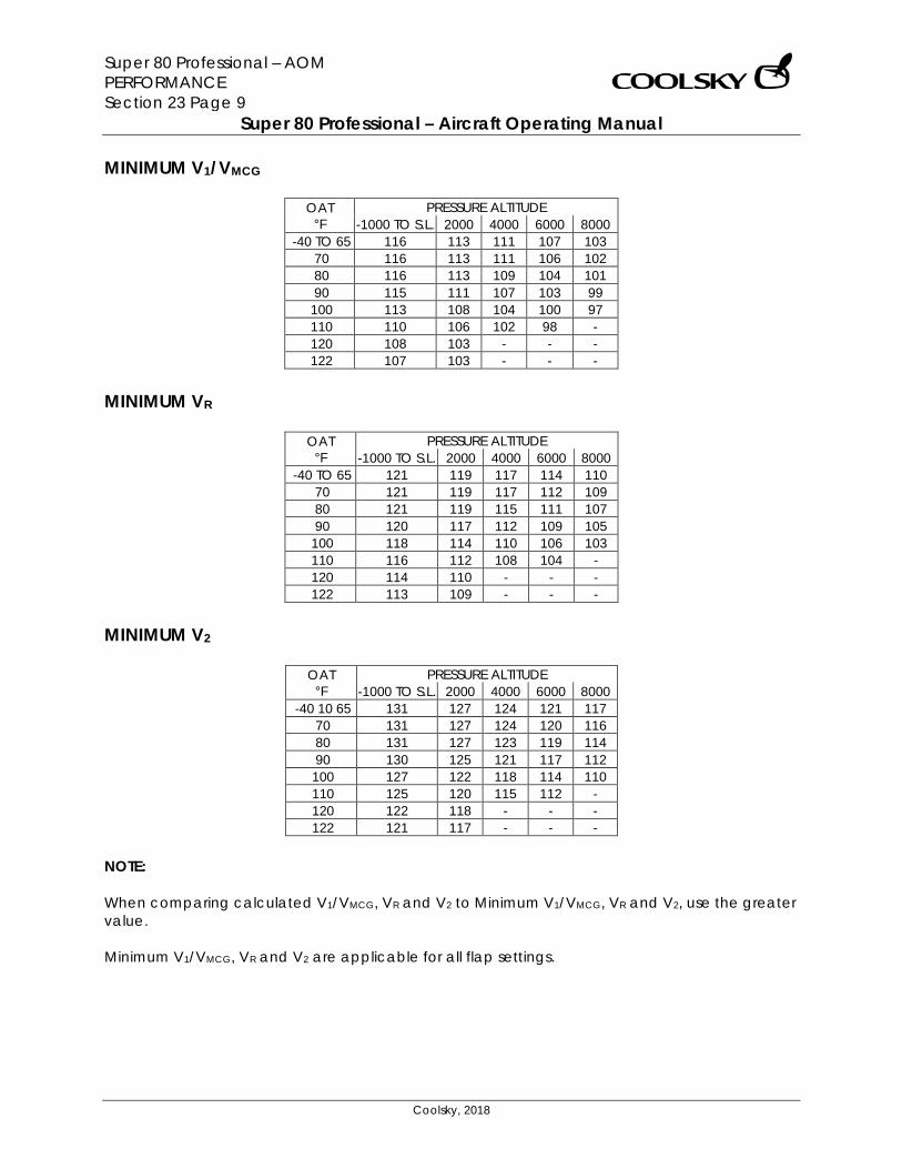
Super 80 Professional – AOM PERFORMANCE Section 23 Page 9
Super 80 Professional – Aircraft Operating Manual
Coolsky, 2018
MINIMUM V1/VMCG
OAT °F
PRESSURE ALTITUDE -1000 TO S.L. 2000 4000 6000 8000
-40 TO 65 116 113 111 107 103 70 116 113 111 106 102 80 116 113 109 104 101 90 115 111 107 103 99
100 113 108 104 100 97 110 110 106 102 98 - 120 108 103 - - - 122 107 103 - - -
MINIMUM VR
OAT °F
PRESSURE ALTITUDE -1000 TO S.L. 2000 4000 6000 8000
-40 TO 65 121 119 117 114 110 70 121 119 117 112 109 80 121 119 115 111 107 90 120 117 112 109 105
100 118 114 110 106 103 110 116 112 108 104 - 120 114 110 - - - 122 113 109 - - -
MINIMUM V2
OAT °F
PRESSURE ALTITUDE -1000 TO S.L. 2000 4000 6000 8000
-40 10 65 131 127 124 121 117 70 131 127 124 120 116 80 131 127 123 119 114 90 130 125 121 117 112 100 127 122 118 114 110 110 125 120 115 112 - 120 122 118 - - - 122 121 117 - - -
NOTE: When comparing calculated V1/VMCG, VR and V2 to Minimum V1/VMCG, VR and V2, use the greater value. Minimum V1/VMCG, VR and V2 are applicable for all flap settings.
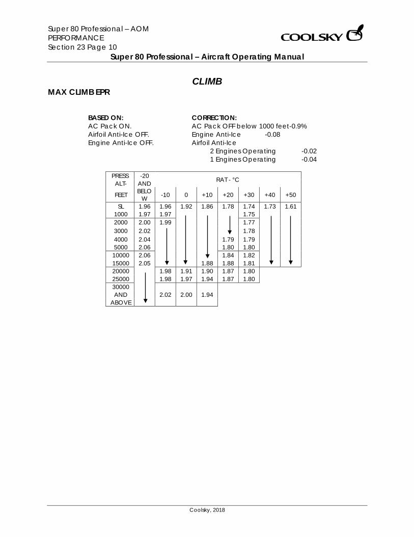
Super 80 Professional – AOM PERFORMANCE Section 23 Page 10
Super 80 Professional – Aircraft Operating Manual
Coolsky, 2018
CLIMB MAX CLIMB EPR
BASED ON: AC Pack ON. Airfoil Anti-Ice OFF. Engine Anti-Ice OFF.
CORRECTION: AC Pack OFF below 1000 feet -0.9% Engine Anti-Ice -0.08 Airfoil Anti-Ice
2 Engines Operating -0.02 1 Engines Operating -0.04
PRESS -20 RAT - °C ALT- AND
FEET BELOW -10 0 +10 +20 +30 +40 +50
SL 1.96 1.96 1.92 1.86 1.78 1.74 1.73 1.61 1000 1.97 1.97 1.75 2000 2.00 1.99 1.77 3000 2.02 1.78 4000 2.04 1.79 1.79 5000 2.06 1.80 1.80
10000 2.06 1.84 1.82 15000 2.05 1.88 1.88 1.81 20000 1.98 1.91 1.90 1.87 1.80 25000 1.98 1.97 1.94 1.87 1.80 30000 AND 2.02 2.00 1.94
ABOVE
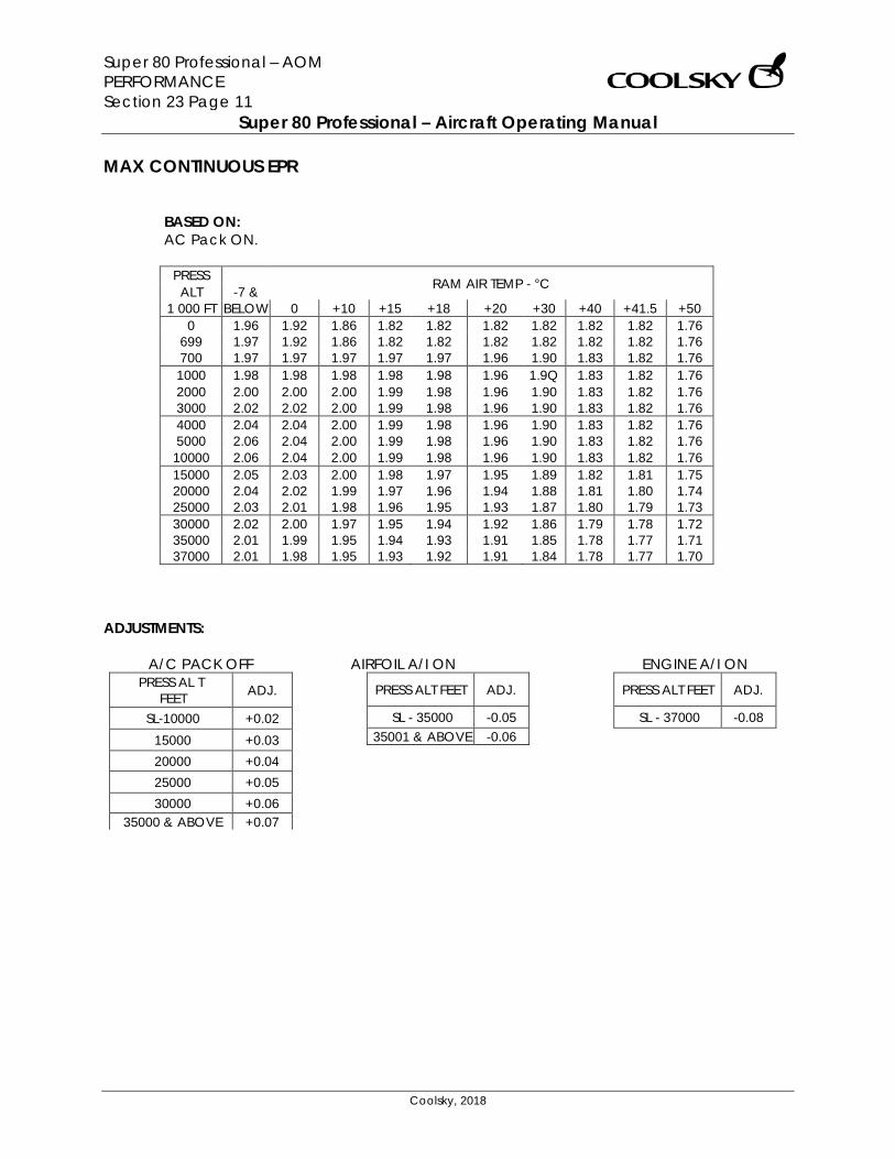
Super 80 Professional – AOM PERFORMANCE Section 23 Page 11
Super 80 Professional – Aircraft Operating Manual
Coolsky, 2018
MAX CONTINUOUS EPR
BASED ON: AC Pack ON.
PRESS RAM AIR TEMP - °C ALT -7 &
1 000 FT BELOW 0 +10 +15 +18 +20 +30 +40 +41.5 +50 0 1.96 1.92 1.86 1.82 1.82 1.82 1.82 1.82 1.82 1.76
699 1.97 1.92 1.86 1.82 1.82 1.82 1.82 1.82 1.82 1.76 700 1.97 1.97 1.97 1.97 1.97 1.96 1.90 1.83 1.82 1.76 1000 1.98 1.98 1.98 1.98 1.98 1.96 1.9Q 1.83 1.82 1.76 2000 2.00 2.00 2.00 1.99 1.98 1.96 1.90 1.83 1.82 1.76 3000 2.02 2.02 2.00 1.99 1.98 1.96 1.90 1.83 1.82 1.76 4000 2.04 2.04 2.00 1.99 1.98 1.96 1.90 1.83 1.82 1.76 5000 2.06 2.04 2.00 1.99 1.98 1.96 1.90 1.83 1.82 1.76
10000 2.06 2.04 2.00 1.99 1.98 1.96 1.90 1.83 1.82 1.76 15000 2.05 2.03 2.00 1.98 1.97 1.95 1.89 1.82 1.81 1.75 20000 2.04 2.02 1.99 1.97 1.96 1.94 1.88 1.81 1.80 1.74 25000 2.03 2.01 1.98 1.96 1.95 1.93 1.87 1.80 1.79 1.73 30000 2.02 2.00 1.97 1.95 1.94 1.92 1.86 1.79 1.78 1.72 35000 2.01 1.99 1.95 1.94 1.93 1.91 1.85 1.78 1.77 1.71 37000 2.01 1.98 1.95 1.93 1.92 1.91 1.84 1.78 1.77 1.70
ADJUSTMENTS:
A/C PACK OFF PRESS AL T
FEET ADJ.
SL-10000 +0.02 15000 +0.03 20000 +0.04 25000 +0.05 30000 +0.06
35000 & ABOVE +0.07
AIRFOIL A/I ON
PRESS ALT FEET ADJ.
SL - 35000 -0.05 35001 & ABOVE -0.06
ENGINE A/I ON
PRESS ALT FEET ADJ.
SL - 37000 -0.08
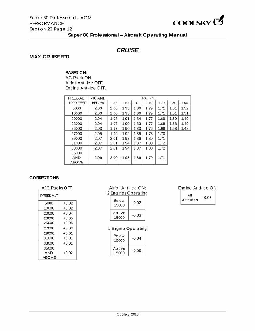
Super 80 Professional – AOM PERFORMANCE Section 23 Page 12
Super 80 Professional – Aircraft Operating Manual
Coolsky, 2018
CRUISE MAX CRUISE EPR
BASED ON: AC Pack ON. Airfoil Anti-Ice OFF. Engine Anti-Ice OFF.
PRESS ALT 1000 FEET
-30 AND BELOW
RAT - °C -20 -10 0 +10 +20 +30 +40
5000 2.06 2.00 1.93 1.86 1.79 1.71 1.61 1.52 10000 2.06 2.00 1.93 1.86 1.79 1.71 1.61 1.51 20000 2.04 1.98 1.91 1.84 1.77 1.69 1.59 1.49 23000 2.04 1.97 1.90 1.83 1.77 1.68 1.58 1.49 25000 2.03 1.97 1.90 1.83 1.76 1.68 1.58 1.48 27000 2.05 1.99 1.92 1.85 1.78 1.70 29000 2.07 2.01 1.93 1.86 1.80 1.71 31000 2.07 2.01 1.94 1.87 1.80 1.72 33000 2.07 2.01 1.94 1.87 1.80 1.72 35000 AND 2.06 2.00 1.93 1.86 1.79 1.71
ABOVE CORRECTIONS:
A/C Packs OFF:
PRESS ALT
5000 +0.02 10000 +0.02 20000 +0.04 23000 +0.05 25000 +0.05 27000 +0.03 29000 +0.01 31000 +0.01 33000 +0.01 35000 AND +0.02
ABOVE
Airfoil Anti-Ice ON: 2 Engines Operating
Below 15000 -0.02
Above 15000 -0.03
1 Engine Operating
Below 15000 -0.04
Above 15000 -0.05
Engine Anti-Ice ON:
All Altitudes -0.08
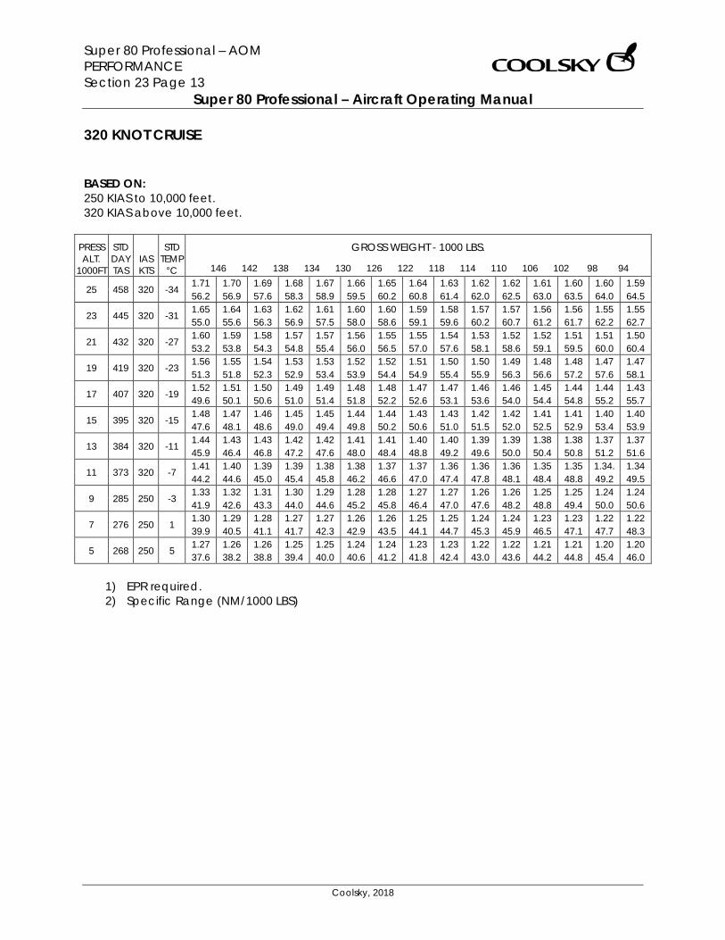
Super 80 Professional – AOM PERFORMANCE Section 23 Page 13
Super 80 Professional – Aircraft Operating Manual
Coolsky, 2018
320 KNOT CRUISE BASED ON: 250 KIAS to 10,000 feet. 320 KIAS above 10,000 feet.
PRESS ALT.
1000FT
STD DAY TAS
IAS KTS
STD TEMP
°C
GROSS WEIGHT - 1000 LBS.
146 142 138 134 130 126 122 118 114 110 106 102 98 94
25 458 320 -34 1.71 1.70 1.69 1.68 1.67 1.66 1.65 1.64 1.63 1.62 1.62 1.61 1.60 1.60 1.59 56.2 56.9 57.6 58.3 58.9 59.5 60.2 60.8 61.4 62.0 62.5 63.0 63.5 64.0 64.5
23 445 320 -31 1.65 1.64 1.63 1.62 1.61 1.60 1.60 1.59 1.58 1.57 1.57 1.56 1.56 1.55 1.55 55.0 55.6 56.3 56.9 57.5 58.0 58.6 59.1 59.6 60.2 60.7 61.2 61.7 62.2 62.7
21 432 320 -27 1.60 1.59 1.58 1.57 1.57 1.56 1.55 1.55 1.54 1.53 1.52 1.52 1.51 1.51 1.50 53.2 53.8 54.3 54.8 55.4 56.0 56.5 57.0 57.6 58.1 58.6 59.1 59.5 60.0 60.4
19 419 320 -23 1.56 1.55 1.54 1.53 1.53 1.52 1.52 1.51 1.50 1.50 1.49 1.48 1.48 1.47 1.47 51.3 51.8 52.3 52.9 53.4 53.9 54.4 54.9 55.4 55.9 56.3 56.6 57.2 57.6 58.1
17 407 320 -19 1.52 1.51 1.50 1.49 1.49 1.48 1.48 1.47 1.47 1.46 1.46 1.45 1.44 1.44 1.43 49.6 50.1 50.6 51.0 51.4 51.8 52.2 52.6 53.1 53.6 54.0 54.4 54.8 55.2 55.7
15 395 320 -15 1.48 1.47 1.46 1.45 1.45 1.44 1.44 1.43 1.43 1.42 1.42 1.41 1.41 1.40 1.40 47.6 48.1 48.6 49.0 49.4 49.8 50.2 50.6 51.0 51.5 52.0 52.5 52.9 53.4 53.9
13 384 320 -11 1.44 1.43 1.43 1.42 1.42 1.41 1.41 1.40 1.40 1.39 1.39 1.38 1.38 1.37 1.37 45.9 46.4 46.8 47.2 47.6 48.0 48.4 48.8 49.2 49.6 50.0 50.4 50.8 51.2 51.6
11 373 320 -7 1.41 1.40 1.39 1.39 1.38 1.38 1.37 1.37 1.36 1.36 1.36 1.35 1.35 1.34. 1.34 44.2 44.6 45.0 45.4 45.8 46.2 46.6 47.0 47.4 47.8 48.1 48.4 48.8 49.2 49.5
9 285 250 -3 1.33 1.32 1.31 1.30 1.29 1.28 1.28 1.27 1.27 1.26 1.26 1.25 1.25 1.24 1.24 41.9 42.6 43.3 44.0 44.6 45.2 45.8 46.4 47.0 47.6 48.2 48.8 49.4 50.0 50.6
7 276 250 1 1.30 1.29 1.28 1.27 1.27 1.26 1.26 1.25 1.25 1.24 1.24 1.23 1.23 1.22 1.22 39.9 40.5 41.1 41.7 42.3 42.9 43.5 44.1 44.7 45.3 45.9 46.5 47.1 47.7 48.3
5 268 250 5 1.27 1.26 1.26 1.25 1.25 1.24 1.24 1.23 1.23 1.22 1.22 1.21 1.21 1.20 1.20 37.6 38.2 38.8 39.4 40.0 40.6 41.2 41.8 42.4 43.0 43.6 44.2 44.8 45.4 46.0
1) EPR required. 2) Specific Range (NM/1000 LBS)
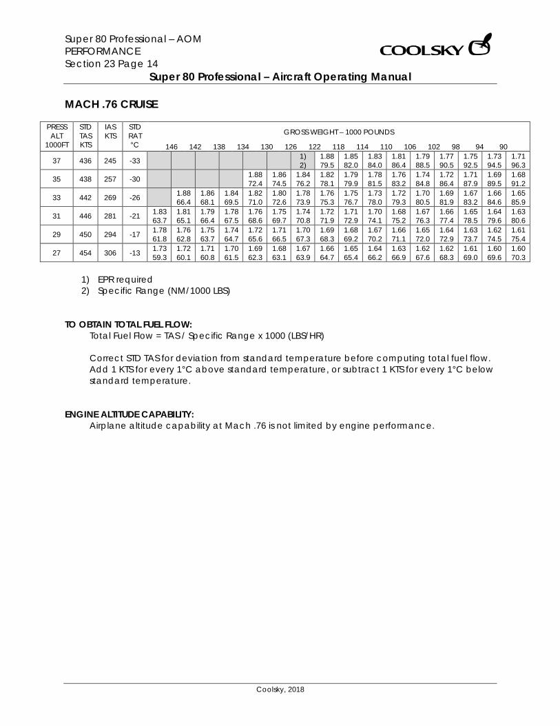
Super 80 Professional – AOM PERFORMANCE Section 23 Page 14
Super 80 Professional – Aircraft Operating Manual
Coolsky, 2018
MACH .76 CRUISE
PRESS ALT
1000FT
STD TAS KTS
IAS KTS
STD RAT °C
GROSS WEIGHT – 1000 POUNDS
146 142 138 134 130 126 122 118 114 110 106 102 98 94 90
37 436 245 -33 1) 2)
1.88 79.5
1.85 82.0
1.83 84.0
1.81 86.4
1.79 88.5
1.77 90.5
1.75 92.5
1.73 94.5
1.71 96.3
35 438 257 -30 1.88 72.4
1.86 74.5
1.84 76.2
1.82 78.1
1.79 79.9
1.78 81.5
1.76 83.2
1.74 84.8
1.72 86.4
1.71 87.9
1.69 89.5
1.68 91.2
33 442 269 -26 1.88 66.4
1.86 68.1
1.84 69.5
1.82 71.0
1.80 72.6
1.78 73.9
1.76 75.3
1.75 76.7
1.73 78.0
1.72 79.3
1.70 80.5
1.69 81.9
1.67 83.2
1.66 84.6
1.65 85.9
31 446 281 -21 1.83 63.7
1.81 65.1
1.79 66.4
1.78 67.5
1.76 68.6
1.75 69.7
1.74 70.8
1.72 71.9
1.71 72.9
1.70 74.1
1.68 75.2
1.67 76.3
1.66 77.4
1.65 78.5
1.64 79.6
1.63 80.6
29 450 294 -17 1.78 61.8
1.76 62.8
1.75 63.7
1.74 64.7
1.72 65.6
1.71 66.5
1.70 67.3
1.69 68.3
1.68 69.2
1.67 70.2
1.66 71.1
1.65 72.0
1.64 72.9
1.63 73.7
1.62 74.5
1.61 75.4
27 454 306 -13 1.73 59.3
1.72 60.1
1.71 60.8
1.70 61.5
1.69 62.3
1.68 63.1
1.67 63.9
1.66 64.7
1.65 65.4
1.64 66.2
1.63 66.9
1.62 67.6
1.62 68.3
1.61 69.0
1.60 69.6
1.60 70.3
1) EPR required 2) Specific Range (NM/1000 LBS)
TO OBTAIN TOTAL FUEL FLOW:
Total Fuel Flow = TAS / Specific Range x 1000 (LBS/HR) Correct STD TAS for deviation from standard temperature before computing total fuel flow. Add 1 KTS for every 1°C above standard temperature, or subtract 1 KTS for every 1°C below standard temperature.
ENGINE ALTITUDE CAPABILITY:
Airplane altitude capability at Mach .76 is not limited by engine performance.
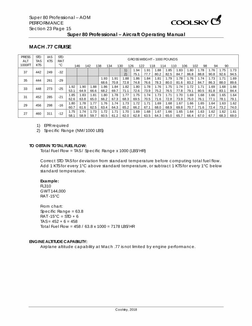
Super 80 Professional – AOM PERFORMANCE Section 23 Page 15
Super 80 Professional – Aircraft Operating Manual
Coolsky, 2018
MACH .77 CRUISE
PRESS ALT
1000FT
STD TAS KTS
IAS KTS
STD RAT °C
GROSS WEIGHT – 1000 POUNDS
146 142 138 134 130 126 122 118 114 110 106 102 98 94 90
37 442 249 -32 1) 2)
1.94 75.1
1.91 77.7
1.88 80.2
1.85 82.5
1.83 84.7
1.80 86.8
1.78 88.8
1.76 90.8
1.75 92.6
1.73 94.5
35 444 261 -29 1.93 68.6
1.91 70.8
1.88 72.8
1.86 74.8
1.84 76.6
1.81 78.3
1.79 80.0
1.78 81.6
1.76 83.2
1.74 84.7
1.73 86.3
1.71 88.0
1.69 89.6
33 448 273 -25 1.92 53.1
1.90 64.9
1.88 66.6
1.86 68.2
1.84 69.7
1.82 71.1
1.80 72.6
1.78 73.9
1.76 75.2
1.75 76.5
1.74 77.8
1.72 79.1
1.71 80.5
1.69 81.8
1.68 83.1
1.66 84.4
31 452 285 -21 1.85 62.6
1.83 63.8
1.81 65.0
1.80 66.2
1.78 67.3
1.77 68.3
1.75 69.5
1.74 70.5
1.73 71.6
1.71 72.8
1.70 73.9
1.69 75.0
1.68 76.1
1.66 77.1
1.65 78.1
1.64 79.1
29 456 298 -16 1.80 60.7
1.78 61.6
1.77 62.5
1.76 63.4
1.74 64.3
1.73 65.2
1.72 66.2
1.71 67.1
1.69 68.0
1.68 68.9
1.67 69.8
1.66 70.7
1.65 71.6
1.64 72.4
1.63 73.2
1.62 74.0
27 460 311 -12 1.75 58.1
1.74 58.9
1.73 59.7
1.72 60.5
1.71 61.2
1.70 62.0
1.69 62.8
1.68 63.5
1.67 64.3
1.66 65.0
1.65 65.7
1.64 66.4
1.63 67.0
1.62 67.7
1.62 68.3
1.61 69.0
1) EPR required 2) Specific Range (NM/1000 LBS)
TO OBTAIN TOTAL FUEL FLOW:
Total Fuel Flow = TAS / Specific Range x 1000 (LBS/HR) Correct STD TAS for deviation from standard temperature before computing total fuel flow. Add 1 KTS for every 1°C above standard temperature, or subtract 1 KTS for every 1°C below standard temperature. Example: FL310 GWT 144,000 RAT -15°C From chart: Specific Range = 63.8 RAT -15°C = STD + 6 TAS = 452 + 6 = 458 Total Fuel Flow = 458 / 63.8 x 1000 = 7178 LBS/HR
ENGINE ALTITUDE CAPABILITY:
Airplane altitude capability at Mach .77 is not limited by engine performance.
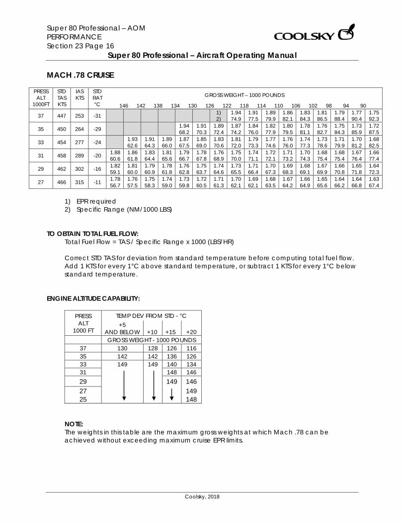
Super 80 Professional – AOM PERFORMANCE Section 23 Page 16
Super 80 Professional – Aircraft Operating Manual
Coolsky, 2018
MACH .78 CRUISE
PRESS ALT
1000FT
STD TAS KTS
IAS KTS
STD RAT °C
GROSS WEIGHT – 1000 POUNDS
146 142 138 134 130 126 122 118 114 110 106 102 98 94 90
37 447 253 -31 1) 2)
1.94 74.9
1.91 77.5
1.89 79.9
1.86 82.1
1.83 84.3
1.81 86.5
1.79 88.4
1.77 90.4
1.75 92.3
35 450 264 -29 1.94 68.2
1.91 70.3
1.89 72.4
1.87 74.2
1.84 76.0
1.82 77.9
1.80 79.5
1.78 81.1
1.76 82.7
1.75 84.3
1.73 85.9
1.72 87.5
33 454 277 -24 1.93 62.6
1.91 64.3
1.89 66.0
1.87 67.5
1.85 69.0
1.83 70.6
1.81 72.0
1.79 73.3
1.77 74.6
1.76 76.0
1.74 77.3
1.73 78.6
1.71 79.9
1.70 81.2
1.68 82.5
31 458 289 -20 1.88 60.6
1.86 61.8
1.83 64.4
1.81 65.6
1.79 66.7
1.78 67.8
1.76 68.9
1.75 70.0
1.74 71.1
1.72 72.1
1.71 73.2
1.70 74.3
1.68 75.4
1.68 75.4
1.67 76.4
1.66 77.4
29 462 302 -16 1.82 59.1
1.81 60.0
1.79 60.9
1.78 61.8
1.76 62.8
1.75 63.7
1.74 64.6
1.73 65.5
1.71 66.4
1.70 67.3
1.69 68.3
1.68 69.1
1.67 69.9
1.66 70.8
1.65 71.8
1.64 72.3
27 466 315 -11 1.78 56.7
1.76 57.5
1.75 58.3
1.74 59.0
1.73 59.8
1.72 60.5
1.71 61.3
1.70 62.1
1.69 62.1
1.68 63.5
1.67 64.2
1.66 64.9
1.65 65.6
1.64 66.2
1.64 66.8
1.63 67.4
1) EPR required 2) Specific Range (NM/1000 LBS)
TO OBTAIN TOTAL FUEL FLOW:
Total Fuel Flow = TAS / Specific Range x 1000 (LBS/HR) Correct STD TAS for deviation from standard temperature before computing total fuel flow. Add 1 KTS for every 1°C above standard temperature, or subtract 1 KTS for every 1°C below standard temperature.
ENGINE ALTITUDE CAPABILITY:
PRESS ALT
1000 FT
TEMP DEV FROM STD - °C +5
AND BELOW +10 +15 +20 GROSS WEIGHT - 1000 POUNDS
37 130 128 126 116 35 142 142 136 126 33 149 149 140 134 31 148 146 29 149 146 27 149 25 148
NOTE: The weights in this table are the maximum gross weights at which Mach .78 can be achieved without exceeding maximum cruise EPR limits.
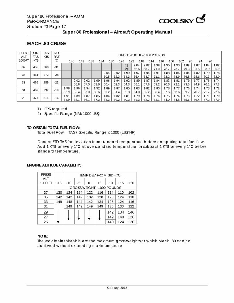
Super 80 Professional – AOM PERFORMANCE Section 23 Page 17
Super 80 Professional – Aircraft Operating Manual
Coolsky, 2018
MACH .80 CRUISE
PRESS ALT
1000FT
STD TAS KTS
IAS KTS
STD RAT °C
GROSS WEIGHT – 1000 POUNDS
146 142 138 134 130 126 122 118 114 110 106 102 98 94 90
37 459 260 -31 1) 2)
2.04 66.6
2.02 68.7
1.99 71.0
1.96 73.7
1.93 73.7
1.89 79.3
1.87 81.5
1.84 83.9
1.82 85.9
35 461 272 -28 2.04 60.5
2.02 62.3
1.99 64.3
1.97 66.4
1.94 68.7
1.91 71.1
1.88 73.2
1.86 74.9
1.84 76.8
1.82 78.6
1.79 80.3
1.78 82.0
33 465 285 -23 2.02 56.6
2.02 57.0
1.99 58.6
1.96 60.4
1.94 62.3
1.92 64.3
1.89 66.1
1.87 67.6
1.84 69.2
1.83 70.6
1.81 72.1
1.79 73.5
1.77 74.9
1.76 76.1
1.74 77.3
31 469 297 -19 1.98 53.9
1.96 55.4
1.94 57.0
1.92 58.6
1.89 60.2
1.87 61.4
1.85 62.8
1.83 64.0
1.82 65.2
1.80 66.4
1.78 67.6
1.77 68.6
1.76 69.7
1.74 70.7
1.73 71.7
1.72 72.6
29 474 311 -16 1.91 53.9
1.89 55.1
1.87 56.1
1.85 57.3
1.84 58.3
1.82 59.3
1.81 60.3
1.79 61.3
1.78 62.2
1.76 63.1
1.75 64.0
1.74 64.8
1.73 65.6
1.72 66.4
1.71 67.2
1.70 67.9
1) EPR required 2) Specific Range (NM/1000 LBS)
TO OBTAIN TOTAL FUEL FLOW:
Total Fuel Flow = TAS / Specific Range x 1000 (LBS/HR) Correct STD TAS for deviation from standard temperature before computing total fuel flow. Add 1 KTS for every 1°C above standard temperature, or subtract 1 KTS for every 1°C below standard temperature.
ENGINE ALTITUDE CAPABILITY:
PRESS ALT
1000 FT
TEMP DEV FROM STD - °C
-15 -10 -5 0 +5 +10 +15 +20 GROSS WEIGHT - 1000 POUNDS
37 130 124 124 122 116 114 110 102 35 142 142 142 132 128 128 124 110 33 149 148 144 142 134 128 124 116 31
149 149 149 149 136 130 122
29 142 134 146 27 142 140 126 25 140 124 120
NOTE: The weights in this table are the maximum gross weights at which Mach .80 can be achieved without exceeding maximum cruise
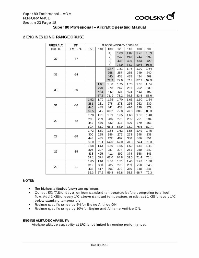
Super 80 Professional – AOM PERFORMANCE Section 23 Page 18
Super 80 Professional – Aircraft Operating Manual
Coolsky, 2018
2 ENGINES LONG RANGE CRUISE
PRESS ALT. 1000 IT.
STD TEMP - °C
GROSS WEIGHT - 1000 LBS 150 140 130 120 110 100 90
37 -57
1) 1.89 1.82 1.76 1.69 2) 247 246 244 237 3) 438 436 433 420 4) 78.9 84.7 90.6 96.0
35 -54
1.87 1.81 1.76 1.70 1.64 258 257 255 249 240 440 438 435 424 409 72.9 77.6 82.4 87.2 92.9
33 -50
1.86 1.80 1.75 1.70 1.65 1. 59 270 270 267 261 252 239 443 443 438 428 413 392 67.6 71. 7 75.2 79.5 83.5 88.6
31 -46
1.92 1.79 1.75 1.70 1.65 1.60 1.54 281 281 278 273 265 252 239 445 445 441 433 420 399 379 62.5 64.2 69.2 72.8 76.3 80.5 85.3
29 -42
1.78 1.73 1.69 1.65 1.60 1.55 1.48 293 289 286 276 265 251 234 442 436 432 417 400 379 353 60.4 63.0 66.3 68.9 72.2 76.5 80.7
27 -38
1.72 1.69 1.64 1.62 1.55 1.49 1.45 300 295 286 276 263 248 238 443 435 422 407 388 366 351 59.0 61.4 64.0 67.0 70.3 74.4 78.3
25 -35
1.68 1.64 1.60 1.55 1.50 1.45 1.41 306 297 287 274 261 250 242 438 425 411 392 374 358 346 57.1 59.4 62.0 64.8 68.0 71.4 75.1
23 -31
1.65 1.61 1.56 1.51 1.46 1.42 1.38 312 300 285 273 259 250 245 433 417 396 379 360 348 341 55.3 57.6 59.8 62.8 65.8 68.7 72.3
NOTES:
• The highest altitudes (grey) are optimum. • Correct STD TAS for deviation from standard temperature before computing total fuel
flow. Add 1 KTS for every 1°C above standard temperature, or subtract 1 KTS for every 1°C below standard temperature.
• Reduce specific range by 5% for Engine Anti-Ice ON. • Reduce specific range by 10% for Engine and Airframe Anti-Ice ON.
ENGINE ALTITUDE CAPABILITY:
Airplane altitude capability at LRC is not limited by engine performance.

Super 80 Professional – AOM PERFORMANCE Section 23 Page 19
Super 80 Professional – Aircraft Operating Manual
Coolsky, 2018
CRUISE MACH/280 KIAS DESCENT BASED ON:
• 800 feet per minute rate of descent at Cruise Mach (0.76) down to Mach Crossover (31,000 feet - 280 KIAS).
• 280 KTS descent thereafter with idle power down to 10,000 feet. • 250 KTS or less (idle power) below 10,000 feet down to initial approach configuration. • Clean configuration above 2000 feet. • Add 80 pounds fuel burn for each minute of terminal area maneuvering.
PRESSURE ALTITUDE
FEET
TO SEA LEVEL
DISTANCE NM
TIME MINUTES
FUEL POUNDS
37,000 150 27.0 1500 35,000 132 24.5 1320 33,000 115 22.0 1050 31,000 96 19.8 900 29,000 89 18.2 860 27,000 82 17.0 820 25,000 75 16.0 790 23,000 69 15.1 760 21,000 63 14.3 730 19,000 58 13.5 700 17,000 53 12.6 680 15,000 48 11.7 660 13,000 43 10.9 640 11,000 38 10.1 620 10,000 33 9.5 600
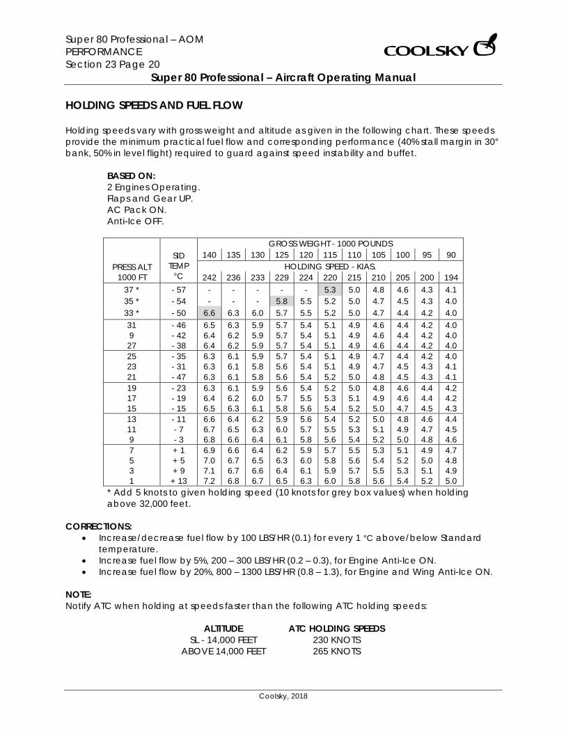
Super 80 Professional – AOM PERFORMANCE Section 23 Page 20
Super 80 Professional – Aircraft Operating Manual
Coolsky, 2018
HOLDING SPEEDS AND FUEL FLOW Holding speeds vary with gross weight and altitude as given in the following chart. These speeds provide the minimum practical fuel flow and corresponding performance (40% stall margin in 30° bank, 50% in level flight) required to guard against speed instability and buffet.
BASED ON: 2 Engines Operating. Flaps and Gear UP. AC Pack ON. Anti-Ice OFF.
GROSS WEIGHT - 1000 POUNDS SID
TEMP °C
140 135 130 125 120 115 110 105 100 95 90 PRESS ALT
1000 FT HOLDING SPEED - KIAS.
242 236 233 229 224 220 215 210 205 200 194 37 * - 57 - - - - - 5.3 5.0 4.8 4.6 4.3 4.1 35 * - 54 - - - 5.8 5.5 5.2 5.0 4.7 4.5 4.3 4.0 33 * - 50 6.6 6.3 6.0 5.7 5.5 5.2 5.0 4.7 4.4 4.2 4.0 31 - 46 6.5 6.3 5.9 5.7 5.4 5.1 4.9 4.6 4.4 4.2 4.0 9 - 42 6.4 6.2 5.9 5.7 5.4 5.1 4.9 4.6 4.4 4.2 4.0 27 - 38 6.4 6.2 5.9 5.7 5.4 5.1 4.9 4.6 4.4 4.2 4.0 25 - 35 6.3 6.1 5.9 5.7 5.4 5.1 4.9 4.7 4.4 4.2 4.0 23 - 31 6.3 6.1 5.8 5.6 5.4 5.1 4.9 4.7 4.5 4.3 4.1 21 - 47 6.3 6.1 5.8 5.6 5.4 5.2 5.0 4.8 4.5 4.3 4.1 19 - 23 6.3 6.1 5.9 5.6 5.4 5.2 5.0 4.8 4.6 4.4 4.2 17 - 19 6.4 6.2 6.0 5.7 5.5 5.3 5.1 4.9 4.6 4.4 4.2 15 - 15 6.5 6.3 6.1 5.8 5.6 5.4 5.2 5.0 4.7 4.5 4.3 13 - 11 6.6 6.4 6.2 5.9 5.6 5.4 5.2 5.0 4.8 4.6 4.4 11 - 7 6.7 6.5 6.3 6.0 5.7 5.5 5.3 5.1 4.9 4.7 4.5 9 - 3 6.8 6.6 6.4 6.1 5.8 5.6 5.4 5.2 5.0 4.8 4.6 7 + 1 6.9 6.6 6.4 6.2 5.9 5.7 5.5 5.3 5.1 4.9 4.7 5 + 5 7.0 6.7 6.5 6.3 6.0 5.8 5.6 5.4 5.2 5.0 4.8 3 + 9 7.1 6.7 6.6 6.4 6.1 5.9 5.7 5.5 5.3 5.1 4.9 1 + 13 7.2 6.8 6.7 6.5 6.3 6.0 5.8 5.6 5.4 5.2 5.0
* Add 5 knots to given holding speed (10 knots for grey box values) when holding above 32,000 feet.
CORRECTIONS:
• Increase/decrease fuel flow by 100 LBS/HR (0.1) for every 1 °C above/below Standard temperature.
• Increase fuel flow by 5%, 200 – 300 LBS/HR (0.2 – 0.3), for Engine Anti-Ice ON. • Increase fuel flow by 20%, 800 – 1300 LBS/HR (0.8 – 1.3), for Engine and Wing Anti-Ice ON.
NOTE: Notify ATC when holding at speeds faster than the following ATC holding speeds:
ALTITUDE ATC HOLDING SPEEDS
SL - 14,000 FEET 230 KNOTS ABOVE 14,000 FEET 265 KNOTS
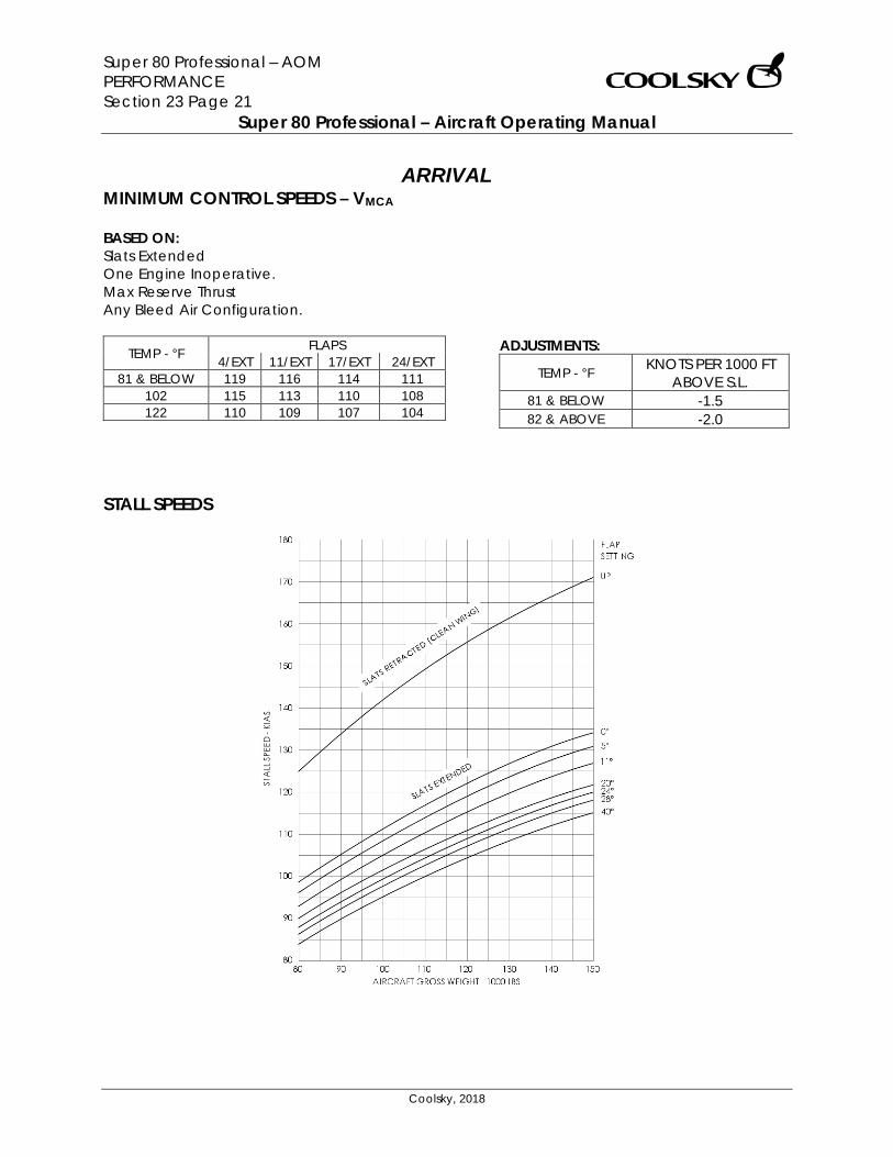
Super 80 Professional – AOM PERFORMANCE Section 23 Page 21
Super 80 Professional – Aircraft Operating Manual
Coolsky, 2018
ARRIVAL MINIMUM CONTROL SPEEDS – VMCA BASED ON: Slats Extended One Engine Inoperative. Max Reserve Thrust Any Bleed Air Configuration.
TEMP - °F FLAPS 4/EXT 11/EXT 17/EXT 24/EXT
81 & BELOW 119 116 114 111 102 115 113 110 108 122 110 109 107 104
ADJUSTMENTS:
TEMP - °F KNOTS PER 1000 FT ABOVE S.L.
81 & BELOW -1.5 82 & ABOVE -2.0
STALL SPEEDS
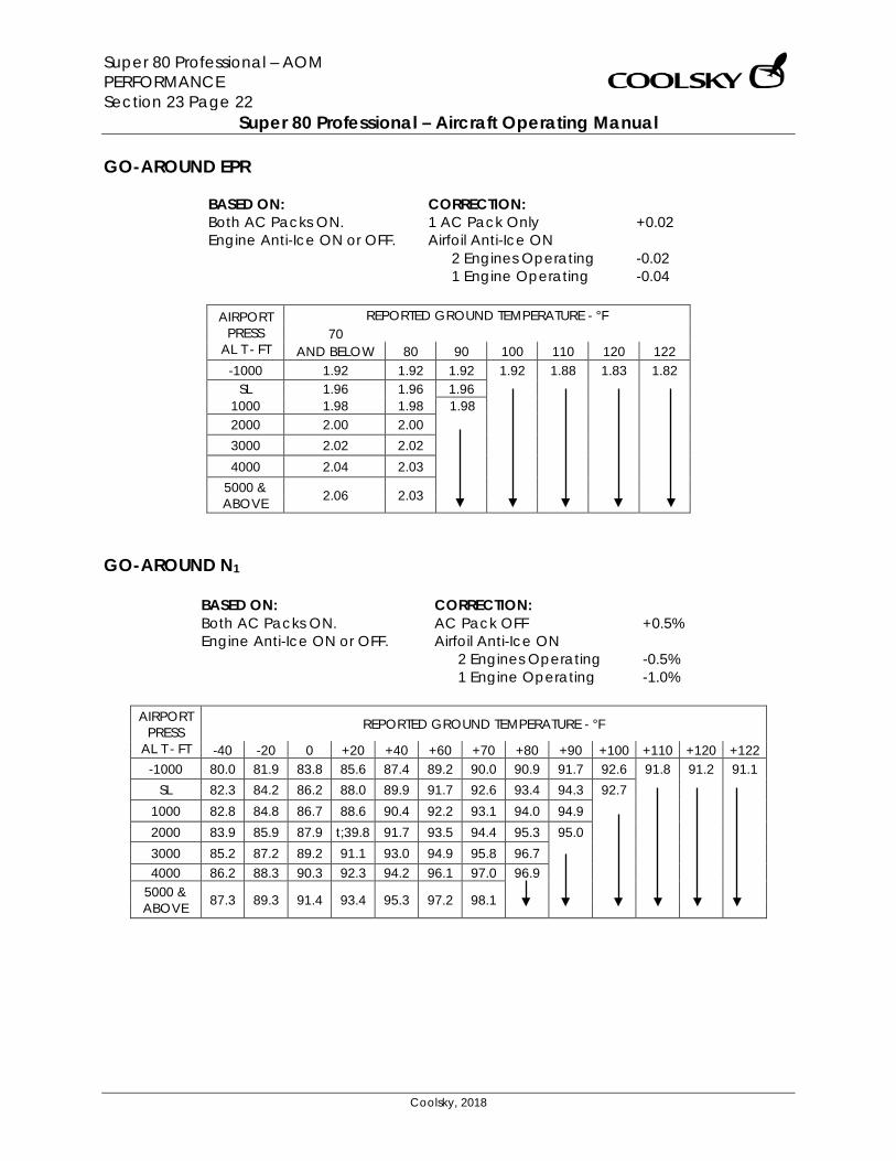
Super 80 Professional – AOM PERFORMANCE Section 23 Page 22
Super 80 Professional – Aircraft Operating Manual
Coolsky, 2018
GO-AROUND EPR
BASED ON: Both AC Packs ON. Engine Anti-Ice ON or OFF.
CORRECTION: 1 AC Pack Only +0.02 Airfoil Anti-Ice ON
2 Engines Operating -0.02 1 Engine Operating -0.04
AIRPORT
PRESS AL T - FT
REPORTED GROUND TEMPERATURE - °F 70
AND BELOW 80 90 100 110 120 122 -1000 1.92 1.92 1.92 1.92 1.88 1.83 1.82
SL 1.96 1.96 1.96 1000 1.98 1.98 1.98 2000 2.00 2.00 3000 2.02 2.02 4000 2.04 2.03
5000 & ABOVE 2.06 2.03
GO-AROUND N1
BASED ON: Both AC Packs ON. Engine Anti-Ice ON or OFF.
CORRECTION: AC Pack OFF +0.5% Airfoil Anti-Ice ON
2 Engines Operating -0.5% 1 Engine Operating -1.0%
AIRPORT
PRESS AL T - FT
REPORTED GROUND TEMPERATURE - °F
-40 -20 0 +20 +40 +60 +70 +80 +90 +100 +110 +120 +122 -1000 80.0 81.9 83.8 85.6 87.4 89.2 90.0 90.9 91.7 92.6 91.8 91.2 91.1
SL 82.3 84.2 86.2 88.0 89.9 91.7 92.6 93.4 94.3 92.7
1000 82.8 84.8 86.7 88.6 90.4 92.2 93.1 94.0 94.9 2000 83.9 85.9 87.9 t;39.8 91.7 93.5 94.4 95.3 95.0 3000 85.2 87.2 89.2 91.1 93.0 94.9 95.8 96.7 4000 86.2 88.3 90.3 92.3 94.2 96.1 97.0 96.9
5000 & ABOVE 87.3 89.3 91.4 93.4 95.3 97.2 98.1
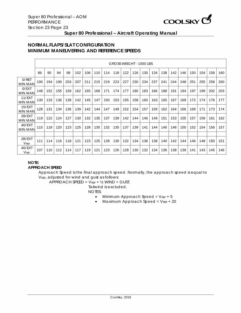
Super 80 Professional – AOM PERFORMANCE Section 23 Page 23
Super 80 Professional – Aircraft Operating Manual
Coolsky, 2018
NORMAL FLAPS/SLAT CONFIGURATION MINIMUM MANEUVERING AND REFERENCE SPEEDS
GROSS WEIGHT - 1000 LBS
86 90 94 98 102 106 110 114 118 122 126 130 134 138 142 146 150 154 158 160
0/RET MIN MAN 190 194 199 203 207 211 215 219 223 227 230 234 237 241 244 248 251 255 258 260
0/EXT MIN MAN 148 152 155 159 162 165 168 171 174 177 180 183 186 188 191 194 197 199 202 203
11/EXT MIN MAN 130 133 136 139 142 145 147 150 153 155 158 160 163 165 167 169 172 174 176 177
15/EXT MIN MAN 128 131 134 136 139 142 144 147 149 152 154 157 159 162 164 166 169 171 173 174
28/EXT MIN MAN 119 122 124 127 130 132 135 137 139 142 144 146 149 151 153 155 157 159 161 162
40/EXT MIN MAN 115 118 120 123 125 128 130 132 135 137 139 141 144 146 148 150 152 154 156 157
28/EXT
VREF 111 114 116 118 121 123 125 128 130 132 134 136 138 140 142 144 146 148 150 151
40/EXT VREF 107 110 112 114 117 119 121 123 126 128 130 132 134 136 138 139 141 143 145 146
NOTE: APPROACH SPEED
Approach Speed is the final approach speed. Normally, the approach speed is equal to VREF, adjusted for wind and gust as follows:
APPROACH SPEED = VREF + ½ WIND + GUST. Tailwind is excluded. NOTES:
• Minimum Approach Speed = VREF + 5 • Maximum Approach Speed = VREF + 20
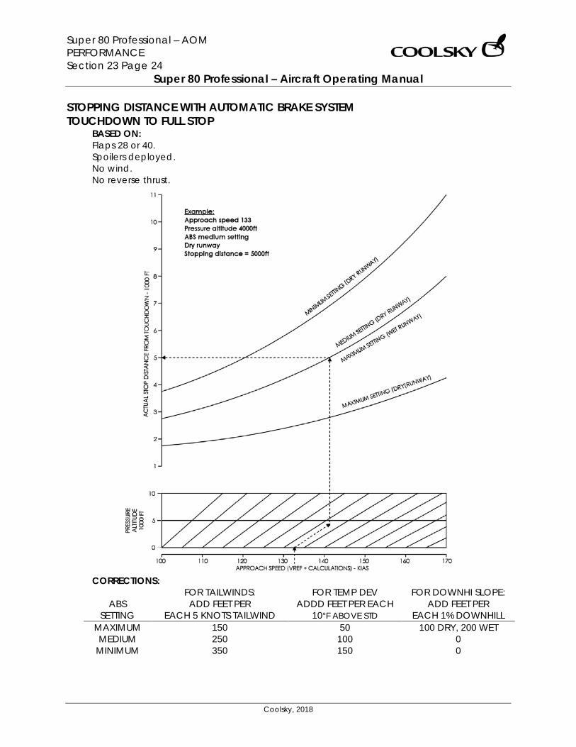
Super 80 Professional – AOM PERFORMANCE Section 23 Page 24
Super 80 Professional – Aircraft Operating Manual
Coolsky, 2018
STOPPING DISTANCE WITH AUTOMATIC BRAKE SYSTEM TOUCHDOWN TO FULL STOP
BASED ON: Flaps 28 or 40. Spoilers deployed. No wind. No reverse thrust.
CORRECTIONS:
ABS SETTING
FOR TAILWINDS: ADD FEET PER
EACH 5 KNOTS TAILWIND
FOR TEMP DEV ADDD FEET PER EACH
10°F ABOVE STD
FOR DOWNHI SLOPE: ADD FEET PER
EACH 1% DOWNHILL MAXIMUM 150 50 100 DRY, 200 WET MEDIUM 250 100 0
MINIMUM 350 150 0
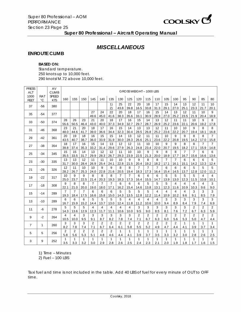
Super 80 Professional – AOM PERFORMANCE Section 23 Page 25
Super 80 Professional – Aircraft Operating Manual
Coolsky, 2018
MISCELLANEOUS ENROUTE CLIMB
BASED ON: Standard temperature. 250 knots up to 10,000 feet. 290 knots/M.72 above 10,000 feet.
PRESS ALT
1000 FEET
RAT °C
AV CLIMB SPEED
KTS
GROSS WEIGHT – 1000 LBS
160 155 150 145 140 135 130 125 120 115 110 105 100 95 90 85 80
37 -56 380 1) 2)
25 43.8
22 39.8
20 16.5
18 33.8
17 31.3
15 29.1
14 27.0
13 25.1
12 23.3
11 21.7
10 20.1
35 -54 377 27 49.6
24 45.0
22 41.6
20 38.3
18 35.6
17 33.1
16 30.9
15 28.9
14 27.0
13 25.2
12 23.5
11 21.9
10 20.4
9 18.9
33 -50 374 28 55.6
26 50.5
23 46.4
21 43.0
20 40.0
18 37.3
17 34.9
16 32.7
15 29.7
14 28.7
13 26.9
12 25.2
11 23.6
11 22.1
10 20.6
9 19.2
8 17.8
31 -46 368 23 48.0
21 44.6
20 41.7
18 39.0
17 36.6
16 34.4
15 32.3
14 30.4
13 28.5
13 26.8
12 25.2
11 23.6
10 22.2
10 20.7
9 19.4
8 18.1
8 16.8
29 -42 361 20 43.5
19 40.7
18 38.7
16 36.0
15 33.9
15 31.9
14 30.0
13 28.3
12 26.6
11 25.1
11 23.6
10 22.2
9 20.8
9 19.5
8 14.2
8 17.0
7 15.8
27 -38 354 18 39.8
17 37.4
16 35.3
15 33.2
14 31.4
13 29.6
12 27.9
12 26.3
11 24.8
10 23.4
10 22.0
9 20.7
9 19.5
8 18.2
8 17.1
7 15.9
7 14.8
25 -34 345 15 35.5
15 33.5
14 31.7
13 29.9
12 28.3
12 26.7
11 29.3
10 23.9
10 22.5
9 21.3
9 20.0
8 18.9
8 17.7
7 16.7
7 15.6
6 16.6
6 13.6
23 -30 335 13 31.7
13 30.0
12 28.4
11 26.9
11 25.4
10 24.1
10 22.8
9 21.5
9 20.4
8 19.2
8 18.2
7 17.1
7 16.1
6 15.1
6 14.2
6 13.3
5 12.4
21 -26 326 12 28.2
11 26.7
10 25.3
10 24.0
9 22.8
9 21.6
8 20.5
8 19.4
7 18.3
7 17.3
7 16.4
6 15.4
6 14.5
6 13.7
5 12.8
5 12.0
5 11.2
19 -22 317 10 25.0
9 23.7
9 22.5
8 21.4
8 20.3
8 19.3
7 18.3
7 17.3
6 16.4
6 15.5
6 14.7
5 13.9
5 13.0
5 12.3
5 11.5
4 10.8
4 10.1
17 -18 308 9 22.1
8 21.0
8 20.0
7 19.0
7 18.0
7 17.1
6 16.2
6 15.4
6 14.6
5 13.8
5 13.1
5 12.3
4 11.6
4 10.9
4 10.3
4 9.6
3 9.0
15 -14 289 7 19.3
7 18.4
7 17.5
6 16.6
6 15.8
6 15.0
5 14.3
5 13.5
5 12.8
5 12.2
4 11.4
4 10.9
4 10.2
4 9.6
3 9.1
3 8.5
3 7.9
13 -10 289 6 16.7
6 15.9
6 15.2
5 14.4
5 13.7
5 13.0
5 12.4
4 11.8
4 11.2
4 10.6
4 10.0
3 9.4
3 8.9
3 8.4
3 7.9
3 7.4
3 6.9
11 -6 278 5 14.3
5 13.6
5 12.9
4 12.3
4 11.7
4 11.1
4 10.6
4 10.0
3 9.5
3 9.0
3 8.5
3 8.1
3 7.6
3 7.2
2 6.7
2 6.3
2 5.9
9 -2 264 4 10.5
4 10.0
3 9.5
3 9.1
3 8.7
3 8.2
3 7.8
3 7.4
2 7.1
2 6.7
2 6.3
2 6.0
2 5.6
2 5.3
2 5.0
2 4.7
2 4.4
7 1 260 3 8.2
3 7.8
3 7.4
2 7.1
2 6.7
2 6.4
2 6.1
2 5.8
2 5.5
2 5.2
2 4.9
2 4.7
2 4.4
1 4.1
1 3.9
1 3.7
1 3.4
5 5 256 2 5.8
2 5.6
2 5.3
2 5.1
2 4.8
2 4.6
1 4.4
1 4.1
1 3.9
1 3.7
1 3.5
1 3.3
1 3.2
1 3.0
1 2.8
1 2.6
1 2.5
3 9 252 1 3.5
1 3.3
1 3.2
1 3.0
1 2.9
1 2.8
1 2.6
1 2.5
1 2.4
1 2.3
1 2.1
1 2.0
1 1.9
1 1.8
1 1.7
1 1.6
0 1.5
1) Time – Minutes 2) Fuel – 100 LBS
Taxi fuel and time is not included in the table. Add 40 LBS of fuel for every minute of OUT to OFF time.
Super 80 Professional – AOM WARNING SYSTEMS Section 24 Page 0
Super 80 Professional – Aircraft Operating Manual
Coolsky, 2018
SECTION 24
WARNING SYSTEMS
Super 80 Professional – AOM WARNING SYSTEMS Section 24 Page 1
Super 80 Professional – Aircraft Operating Manual
Coolsky, 2018
TABLE OF CONTENTS
SECTION 24: WARNING SYSTEMS 0
TABLE OF CONTENTS ................................................................................................................. 1 RADAR ........................................................................................................................................ 2 GROUND PROXIMITY WARNING SYSTEM ............................................................................... 5 WARNING AND CAUTION INDICATORS ................................................................................. 9 TCAS/VSI ................................................................................................................................... 10
Super 80 Professional – AOM WARNING SYSTEMS Section 24 Page 2
Super 80 Professional – Aircraft Operating Manual
Coolsky, 2018
RADAR General A color weather radar system displays weather and ground targets at up to 320 nautical miles range. The radar antenna is gyro stabilized in pitch and roll. The antenna tilt is controllable from 15 degrees up, to 15 degrees down. The digital indicator displays weather or mapping targets in green, yellow and red colors. Areas of light precipitation or ground targets with low level reflectivity are represented by green areas on the display. Areas of lower density precipitation or ground targets with moderate reflectivity are represented by yellow areas on the display. Areas of high density precipitation or ground targets with high reflectivity are represented by red areas on the display. In this panel the targets displayed on the radar screen is actual precipitation as simulated by P3D. However, currently the strength of the targets is not available through the P3D SDK. All targets are therefore indicated as green, i.e. light precipitation.

Super 80 Professional – AOM WARNING SYSTEMS Section 24 Page 3
Super 80 Professional – Aircraft Operating Manual
Coolsky, 2018
1. BRT (Brightness) CONTROL Adjusts the intensity of the display. Currently not simulated. 2. RANGE SELECTOR Selects the range to be displayed. 10 10NM range with 2 range marks at
5NM intervals. 20 20NM range with 2 range marks at
10NM intervals. 40 40NM range with 4 range marks at
10NM intervals. 80 80NM range with 4 range marks at
20NM intervals. 160 160NM range with 4 range marks at
40NM intervals. 320 320NM range with 4 range marks at
80NM intervals. 3. GAIN CONTROL Adjusts radar receiver sensitivity. Currently not simulated.
4. MODE SELECTOR OFF Turns the radar system off. TEST The indicator displays a test pattern
consisting of three arcs; green, yellow and red.
WX The indicator displays areas of high density precipitation in red, lower density precipitation in yellow and light precipitation in green.
TURB Not simulated. MAP Not simulated. 5. STAB SWITCH ON Engages antenna gyro stabilization,
which compensates for airplane roll and pitch.
OFF Disengages antenna gyro stabilization. The antenna is aligned to the airplane fuselage reference plane.
6. ANTENNA TILT CONTROL The tilt control switch is used to vary the vertical scan plane of the outgoing radar beam. Tilt limits are from 15° down to 15° up.
Super 80 Professional – AOM WARNING SYSTEMS Section 24 Page 4
Super 80 Professional – Aircraft Operating Manual
Coolsky, 2018
7. DIGITAL RANGE (RNG) READOUT (Blue) Indicates selected range on the Range Selector. 8. SELECTED MODE READOUT Indicates selected mode on the Mode Selector. 9. DIGITAL RANGE MARK (MRK) READOUT (Blue) Indicates the distance between each range mark. 10. ANTENNA TILT READOUT (Blue) Indicates the antenna tilt angle up or down. 11. WEATHER OR GROUND TARGET Areas of light precipitation or ground targets with low level reflectivity are represented by green areas on the display. Areas of lower density precipitation or ground targets with moderate reflectivity are represented by yellow areas on the display. Areas of high density precipitation or ground targets with high reflectivity are represented by red areas on the display. 12. RANGE MARKS (Blue) 13. AZIMUTH MARKS (Blue)
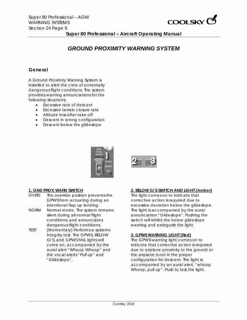
Super 80 Professional – AOM WARNING SYSTEMS Section 24 Page 5
Super 80 Professional – Aircraft Operating Manual
Coolsky, 2018
GROUND PROXIMITY WARNING SYSTEM
General A Ground Proximity Warning System is installed to alert the crew of potentially dangerous flight conditions. The system provides warning annunciations for the following situations:
• Excessive rate of descent • Excessive terrain closure rate • Altitude loss after take-off • Descent in wrong configuration • Descent below the glideslope
1. GND PROX WARN SWITCH OVRD The override position prevents the
GPWS from actuating during an intentional flap up landing.
NORM Normal mode. The system remains silent during all normal flight conditions, and annunciates dangerous flight conditions.
TEST (Momentary) Performs a systems integrity test. The GPWS, BELOW G/S, and GPWS FAIL lights will come on, accompanied by the aural alert “Whoop Whoop” and the vocal alerts “Pull up” and “Glideslope”.
2. BELOW G/S SWITCH AND LIGHT (Amber) The light comes on to indicate that corrective action is required due to excessive deviation below the glideslope. The light is accompanied by the aural annunciation “Glideslope”. Pushing the switch will inhibit the below glideslope warning and extinguish the light. 3. GPWS WARNING LIGHT (Red) The GPWS warning light comes on to indicate that corrective action is required due to airplane proximity to the ground or the airplane is not in the proper configuration for descent. The light is accompanied by an aural alert, “whoop Whoop, pull up”. Push to test the light.
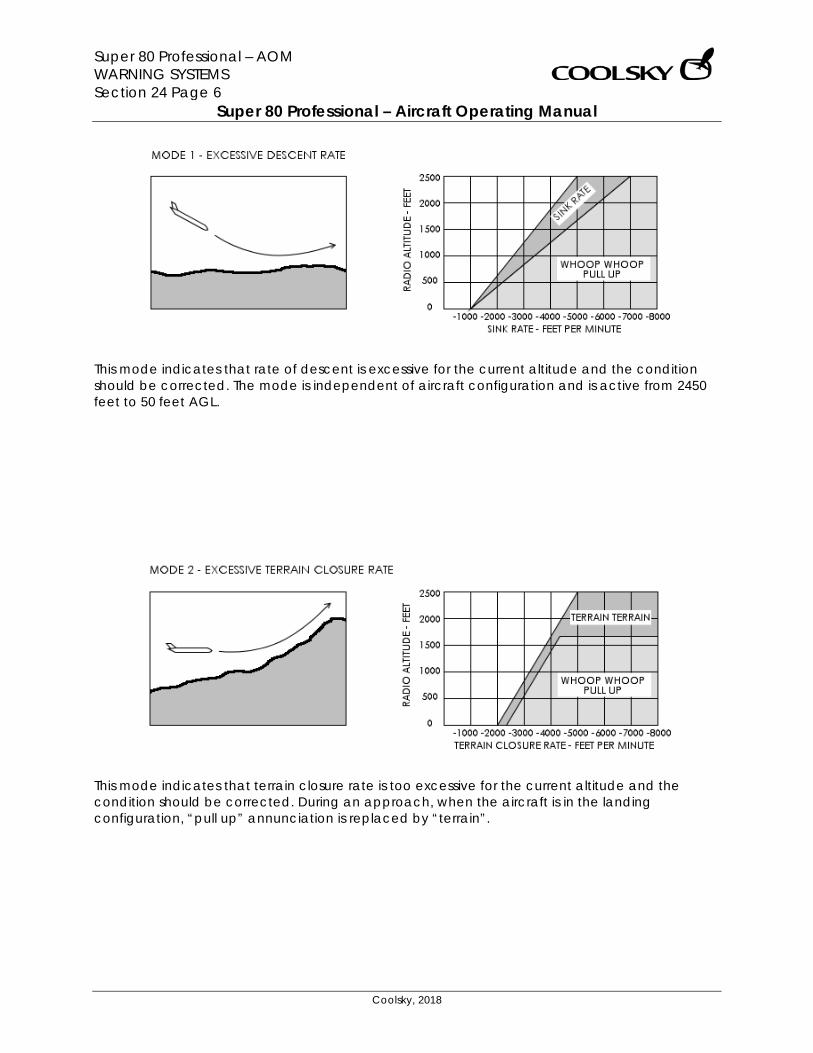
Super 80 Professional – AOM WARNING SYSTEMS Section 24 Page 6
Super 80 Professional – Aircraft Operating Manual
Coolsky, 2018
This mode indicates that rate of descent is excessive for the current altitude and the condition should be corrected. The mode is independent of aircraft configuration and is active from 2450 feet to 50 feet AGL.
This mode indicates that terrain closure rate is too excessive for the current altitude and the condition should be corrected. During an approach, when the aircraft is in the landing configuration, “pull up” annunciation is replaced by “terrain”.
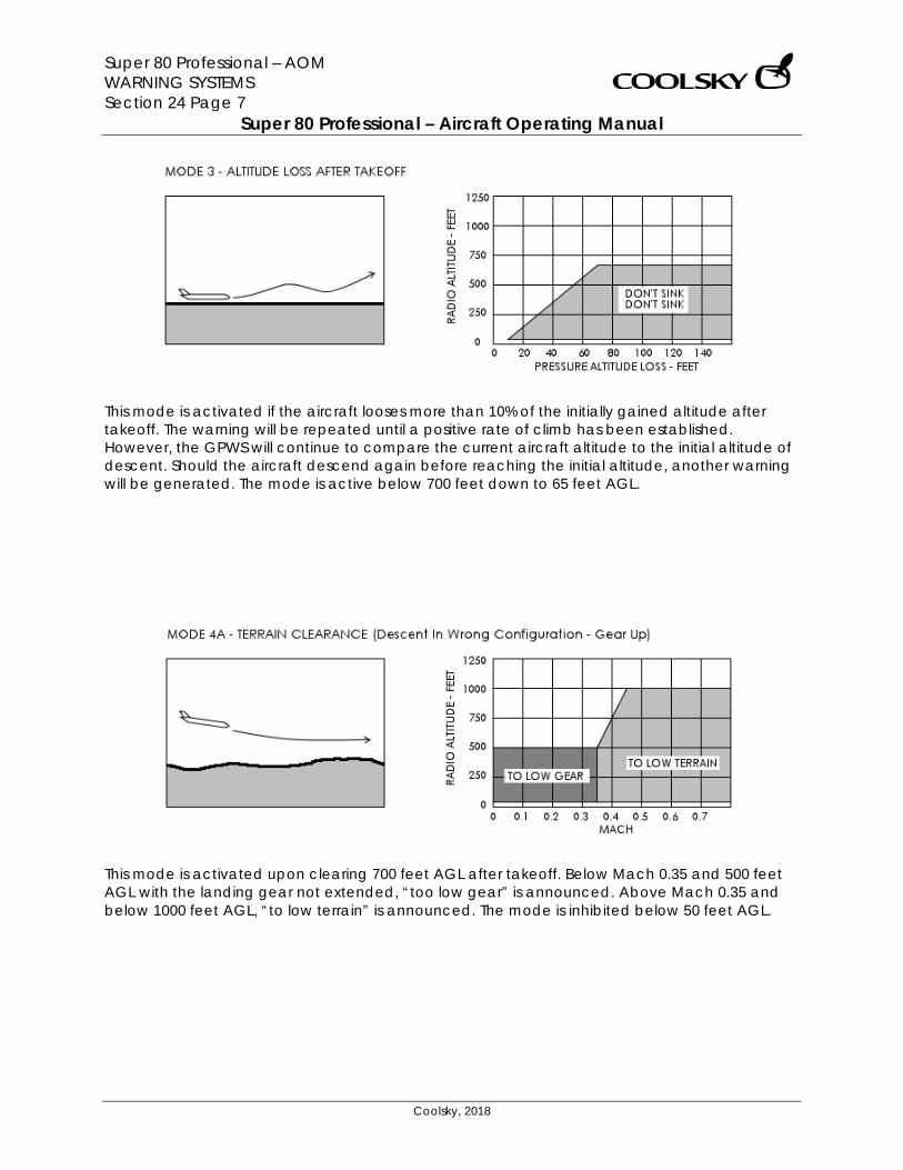
Super 80 Professional – AOM WARNING SYSTEMS Section 24 Page 7
Super 80 Professional – Aircraft Operating Manual
Coolsky, 2018
This mode is activated if the aircraft looses more than 10% of the initially gained altitude after takeoff. The warning will be repeated until a positive rate of climb has been established. However, the GPWS will continue to compare the current aircraft altitude to the initial altitude of descent. Should the aircraft descend again before reaching the initial altitude, another warning will be generated. The mode is active below 700 feet down to 65 feet AGL.
This mode is activated upon clearing 700 feet AGL after takeoff. Below Mach 0.35 and 500 feet AGL with the landing gear not extended, “too low gear” is announced. Above Mach 0.35 and below 1000 feet AGL, “to low terrain” is announced. The mode is inhibited below 50 feet AGL.
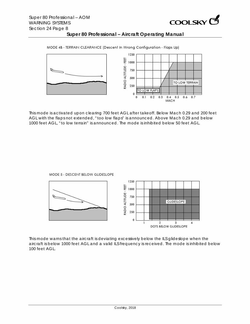
Super 80 Professional – AOM WARNING SYSTEMS Section 24 Page 8
Super 80 Professional – Aircraft Operating Manual
Coolsky, 2018
This mode is activated upon clearing 700 feet AGL after takeoff. Below Mach 0.29 and 200 feet AGL with the flaps not extended, “too low flaps” is announced. Above Mach 0.29 and below 1000 feet AGL, “to low terrain” is announced. The mode is inhibited below 50 feet AGL.
This mode warns that the aircraft is deviating excessively below the ILS glideslope when the aircraft is below 1000 feet AGL and a valid ILS frequency is received. The mode is inhibited below 100 feet AGL.
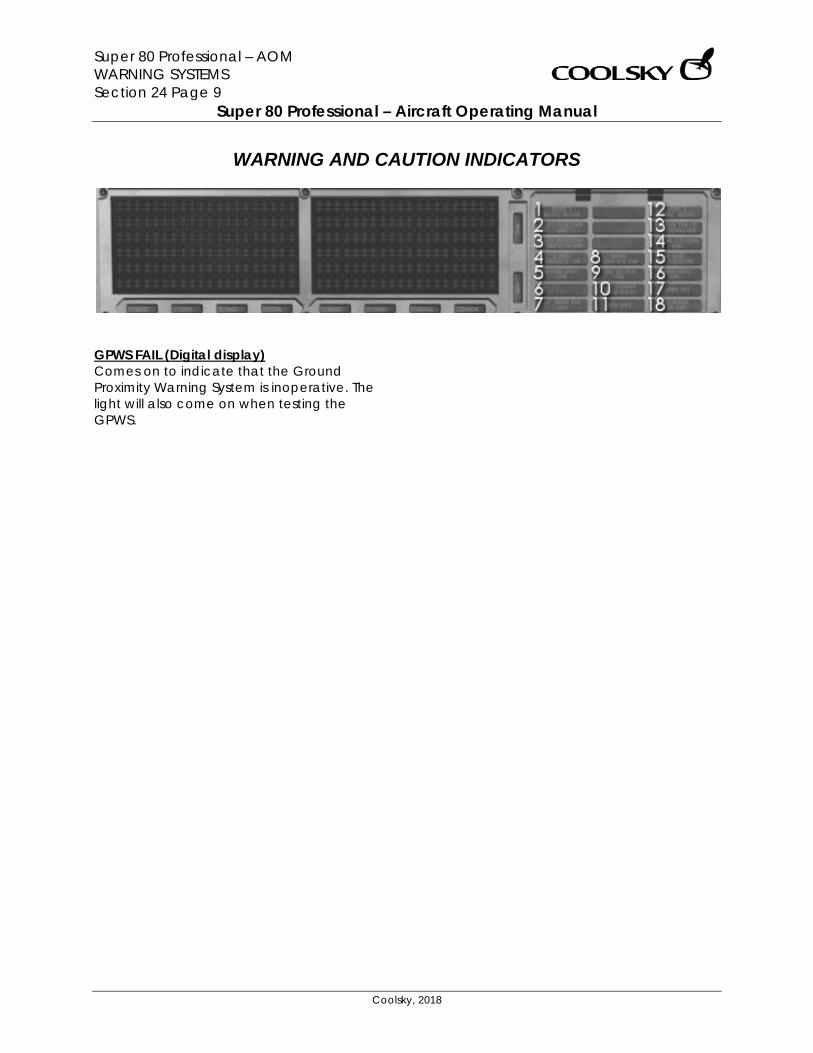
Super 80 Professional – AOM WARNING SYSTEMS Section 24 Page 9
Super 80 Professional – Aircraft Operating Manual
Coolsky, 2018
WARNING AND CAUTION INDICATORS
GPWS FAIL (Digital display) Comes on to indicate that the Ground Proximity Warning System is inoperative. The light will also come on when testing the GPWS.
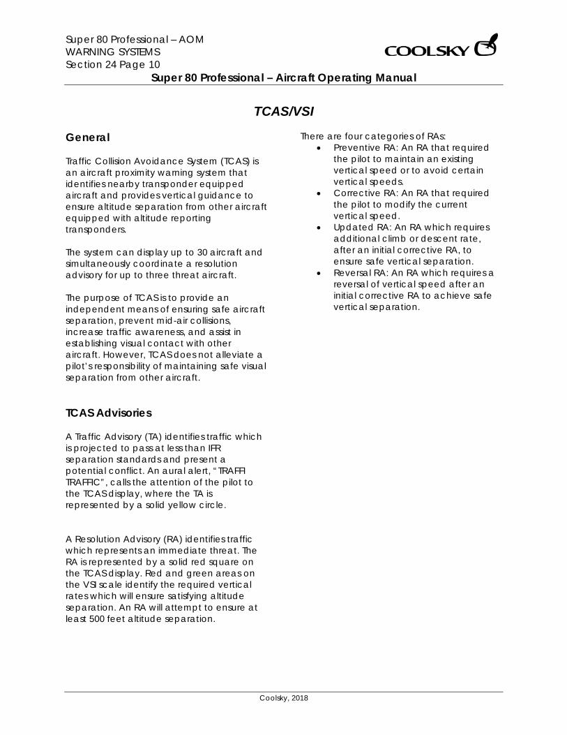
Super 80 Professional – AOM WARNING SYSTEMS Section 24 Page 10
Super 80 Professional – Aircraft Operating Manual
Coolsky, 2018
TCAS/VSI
General Traffic Collision Avoidance System (TCAS) is an aircraft proximity warning system that identifies nearby transponder equipped aircraft and provides vertical guidance to ensure altitude separation from other aircraft equipped with altitude reporting transponders. The system can display up to 30 aircraft and simultaneously coordinate a resolution advisory for up to three threat aircraft. The purpose of TCAS is to provide an independent means of ensuring safe aircraft separation, prevent mid-air collisions, increase traffic awareness, and assist in establishing visual contact with other aircraft. However, TCAS does not alleviate a pilot’s responsibility of maintaining safe visual separation from other aircraft. TCAS Advisories A Traffic Advisory (TA) identifies traffic which is projected to pass at less than IFR separation standards and present a potential conflict. An aural alert, “TRAFFI TRAFFIC”, calls the attention of the pilot to the TCAS display, where the TA is represented by a solid yellow circle. A Resolution Advisory (RA) identifies traffic which represents an immediate threat. The RA is represented by a solid red square on the TCAS display. Red and green areas on the VSI scale identify the required vertical rates which will ensure satisfying altitude separation. An RA will attempt to ensure at least 500 feet altitude separation.
There are four categories of RAs: • Preventive RA: An RA that required
the pilot to maintain an existing vertical speed or to avoid certain vertical speeds.
• Corrective RA: An RA that required the pilot to modify the current vertical speed.
• Updated RA: An RA which requires additional climb or descent rate, after an initial corrective RA, to ensure safe vertical separation.
• Reversal RA: An RA which requires a reversal of vertical speed after an initial corrective RA to achieve safe vertical separation.
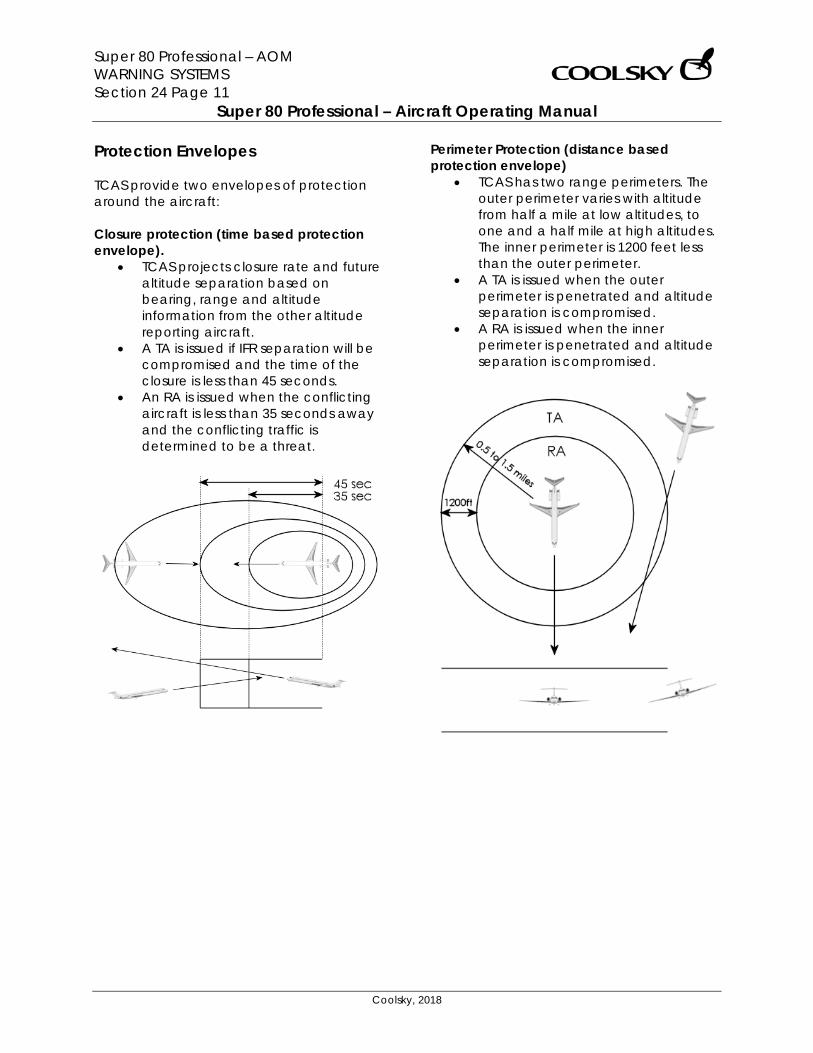
Super 80 Professional – AOM WARNING SYSTEMS Section 24 Page 11
Super 80 Professional – Aircraft Operating Manual
Coolsky, 2018
Protection Envelopes TCAS provide two envelopes of protection around the aircraft: Closure protection (time based protection envelope).
• TCAS projects closure rate and future altitude separation based on bearing, range and altitude information from the other altitude reporting aircraft.
• A TA is issued if IFR separation will be compromised and the time of the closure is less than 45 seconds.
• An RA is issued when the conflicting aircraft is less than 35 seconds away and the conflicting traffic is determined to be a threat.
Perimeter Protection (distance based protection envelope)
• TCAS has two range perimeters. The outer perimeter varies with altitude from half a mile at low altitudes, to one and a half mile at high altitudes. The inner perimeter is 1200 feet less than the outer perimeter.
• A TA is issued when the outer perimeter is penetrated and altitude separation is compromised.
• A RA is issued when the inner perimeter is penetrated and altitude separation is compromised.
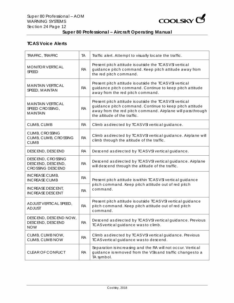
Super 80 Professional – AOM WARNING SYSTEMS Section 24 Page 12
Super 80 Professional – Aircraft Operating Manual
Coolsky, 2018
TCAS Voice Alerts
TRAFFIC, TRAFFIC TA Traffic alert. Attempt to visually locate the traffic.
MONITOR VERTICAL SPEED RA
Present pitch attitude is outside the TCAS VSI vertical guidance pitch command. Keep pitch attitude away from the red pitch command.
MAINTAIN VERTICAL SPEED, MAINTAN RA
Present pitch attitude is outside the TCAS VSI vertical guidance pitch command. Continue to keep pitch attitude away from the red pitch command.
MAINTAIN VERTICAL SPEED CROSSING, MAINTAIN
RA
Present pitch attitude is outside the TCAS VSI vertical guidance pitch command. Continue to keep pitch attitude away from the red pitch command. Airplane will pass through the altitude of the traffic.
CLIMB, CLIMB RA Climb as directed by TCAS VSI vertical guidance.
CLIMB, CROSSING CLIMB, CLIMB, CROSSING CLIMB
RA Climb as directed by TCAS VSI vertical guidance. Airplane will climb through the altitude of the traffic.
DESCEND, DESCEND RA Descend as directed by TCAS VSI vertical guidance.
DESCEND, CROSSING DESCEND, DESCEND, CROSSING DESCEND
RA Descend as directed by TCAS VSI vertical guidance. Airplane will descend through the altitude of the traffic.
INCREASE CLIMB, INCREASE CLIMB RA Present pitch attitude is within TCAS VSI vertical guidance
pitch command. Keep pitch attitude out of red pitch command. INCREASE DESCENT,
INCREASE DESCENT RA
ADJUST VERTICAL SPEED, ADJUST RA
Present pitch attitude is outside TCAS VSI vertical guidance pitch command. Keep pitch attitude out of red pitch command.
DESCEND, DESCEND NOW, DESCEND, DESCEND NOW
RA Descend as directed by TCAS VSI vertical guidance. Previous TCAS vertical guidance was to climb.
CLIMB, CLIMB NOW, CLIMB, CLIMB NOW RA Climb as directed by TCAS VSI vertical guidance. Previous
TCAS vertical guidance was to descend.
CLEAR OF CONFLICT RA Separation is increasing and the RA will not occur. Vertical guidance is removed from the VSIs and traffic changes to a TA symbol.
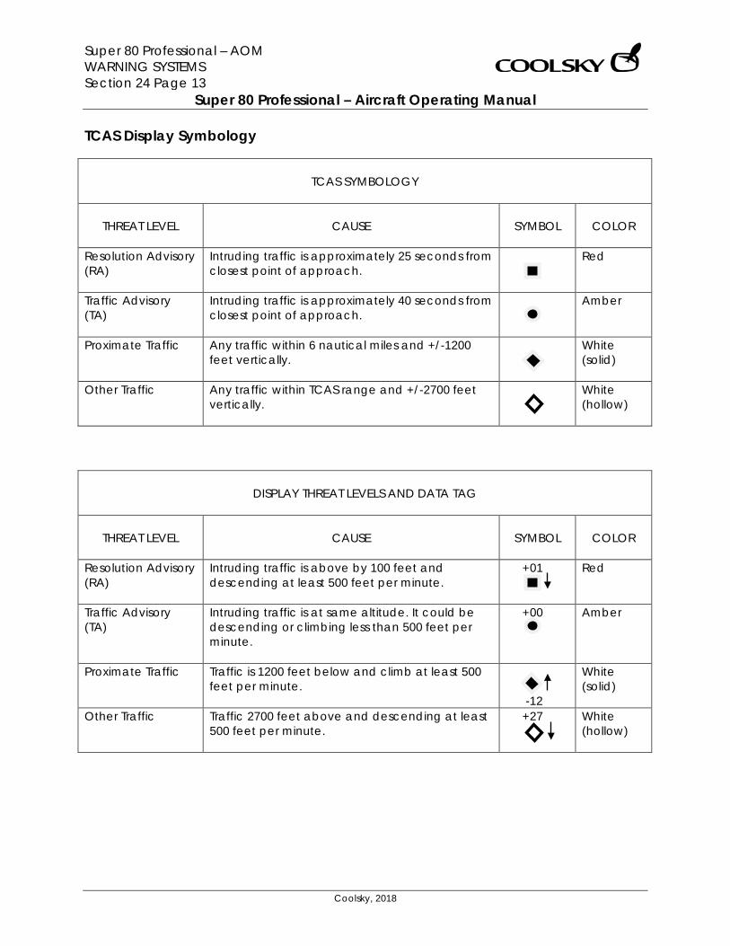
Super 80 Professional – AOM WARNING SYSTEMS Section 24 Page 13
Super 80 Professional – Aircraft Operating Manual
Coolsky, 2018
TCAS Display Symbology
TCAS SYMBOLOGY
THREAT LEVEL
CAUSE
SYMBOL
COLOR
Resolution Advisory (RA)
Intruding traffic is approximately 25 seconds from closest point of approach.
Red
Traffic Advisory (TA)
Intruding traffic is approximately 40 seconds from closest point of approach.
Amber
Proximate Traffic Any traffic within 6 nautical miles and +/-1200 feet vertically.
White (solid)
Other Traffic Any traffic within TCAS range and +/-2700 feet vertically.
White (hollow)
DISPLAY THREAT LEVELS AND DATA TAG
THREAT LEVEL
CAUSE
SYMBOL
COLOR
Resolution Advisory (RA)
Intruding traffic is above by 100 feet and descending at least 500 feet per minute.
+01
Red
Traffic Advisory (TA)
Intruding traffic is at same altitude. It could be descending or climbing less than 500 feet per minute.
+00 Amber
Proximate Traffic Traffic is 1200 feet below and climb at least 500 feet per minute.
-12
White (solid)
Other Traffic Traffic 2700 feet above and descending at least 500 feet per minute.
+27 White (hollow)

Super 80 Professional – AOM WARNING SYSTEMS Section 24 Page 14
Super 80 Professional – Aircraft Operating Manual
Coolsky, 2018
TCAS Inhibits INCREASE DESCENT RAs are inhibited below 1450 feet radio altitude. DESCEND RAs are inhibited below approximately 1,100 feet radio altitude. RAs are inhibited below approximately 1,000 feet radio altitude. Below approximately 1,000 feet when the TA/RA mode is selected on the transponder panel, TA only mode is enabled automatically. All TCAS voice annunciations are inhibited below approximately 500 feet radio altitude. All TCAS alerts are inhibited by GPWS or wind shear warnings. TCAS Limitations TCAS is unable to detect any aircraft without an operating transponder. The TCAS processor does not consider performance issues. High density altitude or an engine inoperative may result in the aircraft being unable to attain the required RA commanded climb rates. The pilot must always respect the performance envelope of the aircraft.
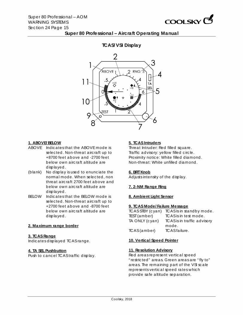
Super 80 Professional – AOM WARNING SYSTEMS Section 24 Page 15
Super 80 Professional – Aircraft Operating Manual
Coolsky, 2018
TCAS/VSI Display
1. ABOVE/BELOW ABOVE Indicates that the ABOVE mode is
selected. Non-threat aircraft up to +8700 feet above and -2700 feet below own aircraft altitude are displayed.
(blank) No display is used to enunciate the normal mode. When selected, non threat aircraft 2700 feet above and below own aircraft altitude are displayed.
BELOW Indicates that the BELOW mode is selected. Non-threat aircraft up to +2700 feet above and -8700 feet below own aircraft altitude are displayed.
2. Maximum range border 3. TCAS Range Indicates displayed TCAS range. 4. TA SEL Pushbutton Push to cancel TCAS traffic display.
5. TCAS Intruders Threat Intruder: Red filled square. Traffic advisory: yellow filled circle. Proximity notice: White filled diamond. Non-threat: White unfilled diamond. 6. BRT Knob Adjusts intensity of the display. 7. 2-NM Range Ring 8. Ambient Light Sensor 9. TCAS Mode/Failure Message TCAS STBY (cyan) TCAS Is in standby mode. TEST (amber) TCAS is in test mode. TA ONLY (cyan) TCAS is in traffic advisory
mode. TCAS (amber) TCAS failure. 10. Vertical Speed Pointer 11. Resolution Advisory Red areas represent vertical speed “restricted” areas. Green areas are “fly to” areas. The remaining part of the VSI scale represents vertical speed rates which provide safe altitude separation.