Embed Size (px)
Citation preview

OPERATING MANUAL
Super 8 ForU


Introduction
With the Super 8 ForU , you have now purchased a product whichhas been manufactured in accordance with the newest technicalcapabilities and based on the highest operating comfort.We have placed great value on the simplest possible operation andlong service life in both construction and material selection.A large variety of useful accessories rounds off our range in additionto the ForU scooter.
This Operating Manual assumes that the suitability of the userfor scooter usage has been discussed with a doctor, therapistand/or dealer before operation.
The operating manual will help you get to know the function of ourForU scooter and, in addition, describes
• operation
• care and maintenance
• repair
The manual has been drawn up using information available at the timeof printing with regard to construction and operation of the scooter.We reserve the right to make changes due to technical improvements.
If you have any other questions about this scooter please contactyour retailer or supplier.
3

Contents1.0 Safety instructions ................................................................……………….8
1.11.21.31.41.51.61.7
Symbols used .............................................................................. 8Intended use ................................................................................ 8General Information ..................................................................... 9Safety when driving .................................................................... 10Safety during transport, assembly and maintenance .................... 11Safety when handling batteries ................................................... 12Safety - information about electronics.......................................... 12
2.03.04.0
5.0
6.0
Versions ............................................................................................ .13Extent of delivery ............................................................................. .13Components ..................................................................................... .144.1 The Midi XMB scooter ................................................................. 144.2 The dashboard - displays and controls ...................................... 14Brief instructions ............................................................................. .155.1 Driving ................................................. .................…155.2 Transporting the scooter… ............................................................17Setting up the scooter…....................................................................... 196.16.2
Adjusting the seat height ........................................................... 19Adjusting the seat position ......................................................... 216.2.16.2.26.2.3
Adjusting the distance between seat and tiller ................ 21Adjusting the armrest width ............................................ 21Adjusting the armrest height ........................................... 22
6.3 Adjusting the tiller angle ............................................................. 237.0 Information about safe driving ........................................... 24
7.17.2
7.37.4
Driving up inclines and down slopes .......................................... 25Overcoming obstacles ............................................................... 267.2.1 Driving Information – Overcoming kerbs .......................27Overload protection - motor protection ....................................... 28Battery charging state = driving range ........................................ 297.4.17.4.27.4.3
Battery charging state .................................................... 29Driving range .................................................................. 30Overdischarge protection - battery protection .................. 30
8.0 Driving ........................................................................... 318.1
8.28.3
8.58.6
4
Getting on and off ...................................................................... 31
Turning the seat ......................................................................... 33Switching on .. . . . . . . . . . . .. . . . . . . . . . . . . . . . . . . . . . . . . . . .. . . . . . . . . . . . . . . . . . .338.3.1 Operation indicator and fault display ...............................33Adjusting the speed ................................................................... 34Before driving ............................................................................ 34

Contents8.78.88.9
Driving ....................................................................................... 35Using the motor brake ................................................................ 35Using the horn ........................................................................... 36
9 . 010.011.0
12.0
13.0
8.10 Switching off / parking .............................................. 36Pushing ...... .. .. .... .... .. ...... ...... .... ...... ...... ...... .... ...... ...... .... 37Attaching the shopping basket .......................................................37Charging the batteries .....................................................................38
11.1Charging the batteries ................................................................391 1 . 1 . 1 C h a r g i n g t h e b a t t e r i e s i n v i a t h e t i l l e r
. . . . . . . . . . . . . . . . . . . . . . . . . . . . . . . . . . . . . . . . . . . . 3 9. . . .11.1.2 LED information at battery charger during charging ........40
11.2After charging ............................................................................ 40Things to know ................................................................................ 4112.1 The battery charger - functioning principle ..................................4112.2 The Batteries ............................................................................. 41
12.2.1 What are batteries for cyclic use? ..................................421 2 2 . 2 W h e n d o t h e b a t t e r i e s a c h i e v e t h e i r m a x i m u m
performance? .................................................................. 4212.2 .3 How d o I make su re t he ba t t e r i es a c h ieve t h e i r
best service life? ............................................................ 4212.3 Anti tipping wheels ..................................................................... 4212.4 Wheels and tyres ....................................................................... 42
12.5 The drive unit ............................................................................. 4312.6 The working principle ................................................................. 4312.7 The control unit .......................................................................... 4412.8 The auto switch-off .................................................................... 4412.9 Brakes . . . . . . . . . . . . . . . . . . . . . . . . . . . . . . . . . . . . . . . . . . . . . . . . . . . . . . . . . . . . . .4412.10 Driver´s licence ...................................................................... 4512.11 Insurance ................................................................................4512.12 Approval for road traffic use ....................................................45Transporting the scooter .................................................................. 4613.1 Transport information ................................................................. 4613.2 Transporting the complete scooter ............................................. 4613.3 Preparation for transport - separating components ..................... 46
13.3.1 Working step summary ...................................................4713.3.2 Removing the seat ..........................................................47
5

Contents13.3.3 Removing the batteries .............................................47
13.3.4 Folding the tiller down ..................................................... 4813.3.5 Disengaging the drive unit from the chassis .................... 48
Cleaning ........................................................................................... ..49Maintenance and Inspection ........................................................... ..5015.1 Daily maintenance before star t of journey .................................. .50
15.3 Annual inspection - inspection timetable ..................................... 51Troubleshooting ................................................................................ 5416.1 Before troubleshooting ................................................................ 5416.2 Troubleshooting ............................................................................5516.3 Operation indicator blink codes ................................................... 57
16.3.1 Blink list ..................................................................... 57
Repairs .............................................................................................. 5817.1 Information about safety at work ................................................ 5817.2 Tools .......................................................................................... 5817.3 Wheels - removal and replacement……………………................. 59
17.5 Replacing the tyre ...................................................................... 6217.6 Fuses ........................................................................................ 6317.7 Batteries .................................................................................... 64
17.7.1 Disposal of used or damaged batteries ..........................6417.7.2 Ref i t t ing bat tery cables . . . . . . . . . . . . . . . . . . . . . . . . . . . . . . . . . . . . . .64
18.0 Temporary storage ........................................................................... 66Appendix .......................................................................................... 67
19.1 Specifications ............................................................................ 6819.1.1 General data ..................................................................68
6

Contents
20.0
19.2 Torque for fixing screws ............................................................. 6919.3 Disposing of the scooter ............................................................ 69Warranty information ....................................................................... 69
Work shop use only... . . .. . . . .. . . . . . . . . . . . . . . . . . . . . . .. . . . . .. . . . . .. . . . . .. . . 70
7

Safety information
1.01.1
Safety instructionsSymbols usedThis instruction manual contains the following symbols which are usedto highlight special hazards in dealing with the product or information forsimplifying the handling.
Caution!This symbol identifies safety information which notifies you ofhazards when dealing with the product.
NOTEYou will also find information about dealing with the productunder this symbol.
1.2 Intended useThe KYMCO Healthcare scooter is constructed for use both indoors(Suggest general use - indoors )and outdoors .
It is intended to increase the mobility of persons who are bothphysically and mentally capable of assessing any driving situationscorrectly and reacting correspondingly to them at any time.
The Super 8 models are classified as an “invalid carriage” for useindoors, on pavements, footpaths, pedestrian zones and areas freefrom motor traffic.They must not be driven on public roads with the exception of crossingor when no pavements are available.
8

Safety information
1.3 General InformationRead the entire operating manual thoroughly before using theSuper 8 ForU!Ensure that:• the operating manual is read by all people who drive, care for and
service the scooter.• all persons who drive, care for, service or repair the scooter have
access to the operating manual at any time.Any damages resulting from nonobservance of this operating manual areexcluded from the guarantee.
Risk of accidents!• Do NOT use the scooter if your driving capability is impaired
through consumption of medicine or alcohol.• Only use the scooter for its correct intended use.• Only use the scooter when it is in perfect working order.• If any breakdowns occur, stop using the scooter immediately
and secure it against unauthorized use.• It is imperative that you always rectify any faults which
could influence the function and safety of the scooterimmediately.
• Observe maximum loading = see Specifications• Only use accessories and spare parts authorized by
KYMCO Healthcare UK Limited.• The scooter is only authorized for transport of one person.• Do not carry out any seat adjustments while driving.
Tipping hazard!• Do not adjust the seat if the scooter is standing on an incline.• Do not lean out over the armrest to the sides or over the
backrest to the rear.
9
Safety information
1.4 Safety when drivingRisk of accidents!• Check correct functioning of the brakes before every journey.• Check the tyre air pressure regularly.• Always use the seat belts when driving.• Do not switch the scooter off while driving.• Do not drive up or down gradients which are too steep, over
obstacles on gradients or up and down ramps.Observe maximum climb angle = see Specifications
• Only drive through restricted widths, around bends, inclinesand ramps with reduced suitable speed.
• Only drive up or down inclines when the backrest has beenadjusted to vertical.
• Don´t drive too close to open waters.
Tipping hazard!• Do not carry out any seat adjustments while driving.• Only drive over obstacles and up kerbstones at the lowest point
and at right angles.• Avoid sudden changes of direction and speed.• Avoid steep gradients where there is a danger of skidding
(ice, snow, wet surfaces etc.).• Avoid loose surfaces whose characteristics you are not able to
assess (woodlands, turf, beaches, gravel etc.)• Always drive straight up and down gradients - do not drive in
zigzags.• Do not turn around on inclines.• Do not drive down steps.• Do not drive backwards down gradients, stairs or kerbstones, or
over obstacles.
10

Safety information
Danger due to unintentional movement!• Always turn the scooter off using the keyswitch if you:
- want to get on or off- intend to stop for long periods- are putting the scooter away.
1.5 Safety during transport, assembly and maintenanceIf the scooter is transported in the vehicle when fullyassembled:- no persons may sit on the scooter during loading!- no persons may sit on the scooter during transport!
Clamping and crushing hazard!Increased hazards due to clamping or crushing result due to thehigh component weight (such as batteries) during preparationfor transport and maintenance work.
• Always carry out any work to be done with great care.• Always try to get help from a second person, especially when
stowing parts for transport.• Only carry out any work described if you are used to working
with the tools required.• Only carry out work using suitable tools.
Injury hazard due to improper assembly!• Ensure that all components in the Scooter have been
correctly assembled.• After assembly, check that all locking devices are holding
correctly.
Accident hazard due to incorrectlybolted connections!• If bolted connections have self-locking nuts, ensure
that these are replaced when reassembling.• Do not replace self-locking nuts with normal nuts.• If bolted connections have lock washers, check lock
washers when reassembling and replace if necessary.
11

Safety information
1.6 Safety when handling batteriesFire hazard!• Do not cover the battery charger and ventilation slot while
charging batteries.
• Only use the battery charger in well-ventilated areas.Risk of accidents!• Only use the original battery charger (included in delivery).• Let your dealer replace your battery.• Only use batteries as detailed in the chapter entitled
“Specifications”.• Observe warning information given by the battery
manufacturer.• Batteries are extremely heavy.Burn hazard due to damaged batteries!Batteries discharging acid can lead to serious burns.• Do not touch damaged batteries with your bare hands. Use
rubber gloves!• If acid should contact your skin, wash the affected area
immediately with plenty of water and contact a doctor.• If acid should come in contact with your eyes, rinse them out
immediately with lots of water and visit a doctor.• Always change any clothing soiled with battery acid
immediately.
Safety - information about electronicsAccident hazard due to failures!Radio, television, radio transmission devices and mobile phonesproduce electromagnetic fields. These can negatively influencethe scooter electronics functions.• Do not drive close to strong radio or television transmitters
(transmitter masts).• Switch the scooter off if you are using your mobile phone.Interference caused to other devices!The scooter produces an electromagnetic field which cannegatively affect functioning of electrical devices such asmedicinal devices, radio receivers or mobile telephones withinthe vicinity.
1.7
12

Versions
2.0 Versions
3.0 Extent of deliveryAfter receiving your ForU scooter,please check the following:• that the delivery is complete in
accordance with the list below• the delivery condition using the
inspection plan (chapter 14.2)If any faults are apparent orcomponents are missing, pleasecontact your supplier or dealer.
The following items are included indelivery in addition to the scooter:
1. Shopping basket2. Two vehicle keys for switching
the on/off3. Battery charger4. Operating Manual
13

Components
4.0 Components
4.2 The dashboard - displays and controls
14
Dashboard with controls4.1 The ForU scooter
Seat unit withhead and armrestsShopping basket
Anti tipperSteering wheel
Tiller
Indicators andposition light
Indicators andposition light
Speed contollerOperation indicator(fault display)
Battery chargedisplay
Drive lever(reverse)
Horn
Headlightswitch
Drive lever(forward)
Indicatorswitch
Key switchChargingsocket H/ L speed
switch

Brief instructions
5.0 Brief instructionsThe following brief instructions should enable people to quickly get usedto operating the scooter after a long period of non-use and to refreshexisting knowledge of operation.It is imperative that you follow the instructions given in the mainmanual!
5.1 Driving the scooterNOTEBefore starting driving, adjust the seat height, thebackrest and the armrests to a comfortable position.Your specialist dealer would be very glad to help.
1.) Turn the seat to the outside. 2.) Get in - turn the seat in thedirection of travel
3.) Switch on the scooter
15
ON

Brief instructions
4.) Check the batterycharging state
5.) Set the maximum speed
= lowest possible drivingspeed (approx. 4mph)
= highest possible drivingspeed (approx. 6mph)
6.) DrivingOperate the drive lever slowly until the required speed has been reached
The drive lever position controls thespeed variably right up to maximum
driving speed.
1Standstill
(brake engaged)Standstill(brake engaged)
Reverse Forwards
8.) Horn 9.) position light7.) Braking = release drivelever (1)
16
Red-reserveYellow-mediumGreen-full
(1) (8) (9)

Brief instructions
5.2 Transporting the scooterDismantling the scooter (stages 1 to 9)
2.) Removing the rear panelling1.) Remove the seat
4.) Remove the battery plug and front connector
17
3.) Remove the l ighting cable
6.) Fold the tiller down5.) Remove the battery belts andbatteries

Brief instructions
Reassembling the scooter(Stages 9 to 1)
The scooter dismantled:1. Chassis2. Batteries2. Drive unit3. Rear panelling4. Seat unit
18
7.) Unlock the drive unit 8.)Tilt the drive unit away
9.)Remove the chassis
Step
Step
Step

Adjusting the seat height
6.0 Setting up the scooterThe following passage describes how to set up your scooter in order toensure that you have a comfortable and safe drive.
6.1 Adjusting the seat heightNOTE!The seat must be removed from the scooter in order to adjust theseat height. You should try to get help from a second person ifpossible or contact your dealer.
Removing the seatRemoving the seat: Tilt the backrest forwards.
Lift the seat while pulling the seatlock (a) out of the seat support (1).
19
Adjusting the seat height: Removing the clampingbolt and hold boltRemove the clamping bolt (1)
and hold bolt.(2)Out of the seat support (3).1xRing spanner, size 12mm1x Hexagon bolt.
(a)(1)

Adjusting the seat height
20
The seat height (h) is adjusted using thefive holes (1-4) in the seat support.
Pull the seat support (4) out as far asthe required height until the correcthole (1-4) appears in the seat tubehole (5).Push the clamping bolts (6) into the seattube from the front.
h
4 holes
In order to avoid dangerwhen driving. Pleaseadjust the height of seat,and then confirm if theseat’s bolt is at the rightposition, otherwise, theseat would be shaked.

Adjusting the seat height
21
Inserting the seat: Pull the seat lock (a) and guide the seat
into the seat support (1) from above. Let go off the seat lock and engage
the rotational adjustment by turning theseat a little one way then the other.
Inserting the seat
NOTEIf after inserting the seat it isnot possible to turn the seat orto pull the seatlock, the seat isnot properly locked.
(a)(1)

Adjusting the seat
22
6.2 Adjusting the seat positionAdjusting the distance between seat andtillerPull the locking lever (1) upwards and movethe seat forwards or backwards to therequired distance.Let go of locking lever and engage thelocking mechanism by pushing the seatslightly forwards and backwards.
Moving the seat
Accident hazard due tonon-engaged seat!• Ensure that the seat is properly
engaged after adjustment bypushing the seat slightly forwardsand then backwards.
Adjusting the armrestwidth6.2.2 Adjusting the armrest width
Loosen both clamping screws (2). Pull both armrests (3) simultaneously
to the required width. Secure the armrests by tightening
the clamping screws.
CAUTION!• Do not pull the armrests further
out than the marking (a) formaximum armrest width.
6.2.1
(1)
(2)
(3)
(a)

Adjusting the seat
23
6.3 Adjusting the tiller angleAlways adjust the tiller so that you canreach all displays and controls easily at anytime. The tiller can be variably adjusted.
adjusting the tiller
Turn and loose the locking lever(1) Pull the tiller for backwards into the
required position . Tighten the locking lever . Ensure that the tiller is engaged
properly by moving slightly forwards
and backwards.
Accident hazard due tonon-engaged tiller!• Ensure that the tiller is properly
engaged after adjustment bypushing it slightly forwards andthen backwards.
(1)

24
Driving information
7.0 Information about safe d r iving
Always carry out the safety information described inchapter 1.4 “Safety when driving“!
Driving is very simple and after a few practice sessions you willFind it very easy.
The following information should help you to drive safely through traffic:
• always match your speed to the driving situation in which you findyourself.always reduce the speed when you are driving through:- unclear areas- narrow gaps- tight curves- inclines- rampstake a trial run with your scooter in an area with no pedestrians,or in a closed-off area.
always steer the scooter using both hands on the handlebars.
always keep your feet in the foot area while driving .
•
•
••

25
Driving information
7.1 Driving up inclines and down slopes
Climb angle examples:a 1 metre long ramp should not be higher than. 18 cma 2 metre long ramp should not be higher than. 36 cm
• Avoid driving across an incline(always try to drive in the directionof the incline / decline).
Tippinghazard!
There is an increased danger of tippingwhen climbing or descending gradients if:
• the scooter is loaded at the back andadditionally the seat has been adjustedto its rear position.
You can achieve increased tipping safety if:
• you adjust the seat in a more forwardposition.
• you lean your upper body slightlyforwards (see sketch).
Increasedtipping safety
The scooter will slow down to a safe reduced speed to protect themotor if in overload/ over heated conditions.Please switch off and allow the motor to cool down beforecontinuing your journey.You may need to choose an alternative more suitable route ifoverload trip re-occurs.

26
Driving information
7.2 Overcoming obstaclesThe scooter can climb over obstaclessuch as kerbstones up to height of 8cm without any problem.Please observe the following points to makesure that your scooter doesn’t tip over whileclimbing obstacles:
• don’t try to drive over obstacles whichare too highexample: kerbstonesremedy: always climb up kerbstones
at lowered entry areassuch as driveways.
• Do NOT try to climb an obstacle when onan incline.
••
approach the obstacle at a right angletry to clear the obstacle in one go.
• DO NOT drive over the obstacle with justone wheel.
• DO NOT drive backwards over an obstacle.
• DO NOT drive backwards down a kerb.
• DO NOT drive down stairs or steps.
6 cm
6 cm
88

Driving information
27
7.2.1 Driving Information – Overcoming kerbs
Risk of accidents!Neogating kerbs needs some practice.• Please observe the maximum obstacle hights of 8 cm.• Please start practicing kerb climbing with small kerbs.
Approach at a right angle
Approach the kerb at a right angle.
Stop in front of the kerb
Stop approximately 0.5 Meter /19 inches in front of the kerb.
Adjust the speed-controller
Adjust the speed controller to maximumspeed.
Press the drive lever fully forward and tryto clear the kerb in one go.The speed of the scooter should only beat 1 mph when the front wheels hit thekerb.
Overcome kerb
Keep the drive lever in the fully forwardsposition until the rear wheels have clearedthe kerb.

Driving information
28
7.3 Overload protection - motor protectionThe overload protection switches the drive off if the motor becomesoverloaded by trying to climb over too high an obstacle such as akerbstone, or if you try to climb too steep of an incline.
If the motor is overloaded, the following happens:• the scooter becomes noticeably slower and then stops
• the control system switches the scooter off
To rectify this:
Switch the scooter off and allow it to cool down for a few minutes.Switch the scooter on again and ...... reverse away from the obstacle (such as kerbstone) and then
try again at a lower point.... be careful turning the scooter around on inclines, and always
reverse away very slowly.
Tipping hazard!There is an increased tipping hazard if the incline is very steep.• Try to get help from a second person when turning your
scooter around.
Accident hazard in push mode!If the incline is too steep, there is a danger that you will notbe able to hold onto the scooter and that it will roll down theincline uncontrolled.• Try to get help from a second person when turning your
scooter around.

Driving information
29
7.4 Battery charging state = driving range
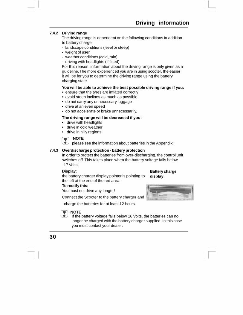
7.4.1 Battery charging state Battery charge display
Battery charge display:The battery charger display on thedashboard shows the battery charging state.
Display rangesFull = maximum rangeMedium = decreased driving range, charge
batteries after journeyReserve = minimum driving range, end
journey as soon as possible,charge batteries
Important information about reading the battery charge display:• If the scooter is at standstill, it is often the case that the battery
charging state is shown higher than it actually is.The display can vary greatly while the vehicle is travelling (dependingon load).If the vehicle is under heavier loading (for example heavyacceleration, driving up hills), the pointer can sometimes go to the redarea of the display. This is not critical and does not indicate the actualcharging state of the batteries.If the pointer has gone into the red area of the display after thejourney, it will often show green after the scooter has been turned offfor a long period.This does not indicate the actual charging state of the batteries!If the pointer is in the red area of the display at the end of the journey,the batteries must be charged before continuing the journey.Disregarding this can lead to destruction of the batteries!
•
•
•
Determining the actual charging state: Drive at a constant speed for about 200 m along a straight level
route. The value shown by the display during the journey is theactual battery charging state.
Red-reserveYellow-mediumGreen-full
Driving information
30
7.4.2 Driving rangeThe driving range is dependent on the following conditions in additionto battery charge:----
landscape conditions (level or steep)weight of userweather conditions (cold, rain)driving with headlights (if fitted)
For this reason, information about the driving range is only given as aguideline. The more experienced you are in using scooter, the easierit will be for you to determine the driving range using the batterycharging state.
You will be able to achieve the best possible driving range if you:•••••
ensure that the tyres are inflated correctlyavoid steep inclines as much as possibledo not carry any unnecessary luggagedrive at an even speeddo not accelerate or brake unnecessarily.
The driving range will be decreased if you:•••
drive with headlightsdrive in cold weatherdrive in hilly regions
NOTEplease see the information about batteries in the Appendix.
7.4.3 Overdischarge protection - battery protectionIn order to protect the batteries from over-discharging, the control unitswitches off. This takes place when the battery voltage falls below 17 Volts.Display:the battery charger display pointer is pointing tothe left at the end of the red area.To rectify this:You must not drive any longer!Connect the Scooter to the battery charger and
charge the batteries for at least 12 hours.
Batterychargedisplay
NOTEIf the battery voltage falls below 16 Volts, the batteries can nolonger be charged with the battery charger supplied. In this caseyou must contact your dealer.
31
Driving
8.08.1
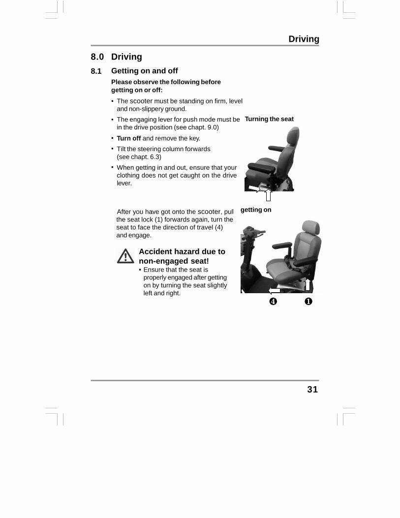
DrivingGetting on and offPlease observe the following beforegetting on or off:• The scooter must be standing on firm, level
and non-slippery ground.The engaging lever for push mode must bein the drive position (see chapt. 9.0)
Turn off and remove the key.Tilt the steering column forwards(see chapt. 6.3)When getting in and out, ensure that yourclothing does not get caught on the drivelever.
Turning the seat•
••
•
getting on After you have got onto the scooter, pullthe seat lock (1) forwards again, turn theseat to face the direction of travel (4)and engage.
Accident hazard due tonon-engaged seat!• Ensure that the seat is
properly engaged after gettingon by turning the seat slightlyleft and right.

32
DrivingNOTE!If you feel you are safe enough, youcan of course get onto the scooterwithout turning the seat round.• You can lift up the armrest on the
side where you are standing andthen get on.

Driving
33
8.2 Turning the seatThe seat can be turned to both sides of theangle, and firmly engaged in 8 positions(each position turns 45°).
Turning the seat: Pull the turning lock (1), turn the seat
in the required direction or position (2)and engage.
Accident hazard due toincorrect seat position!• Always turn the seat to face
forwards and engage it beforedriving.
If the seat has been turned, thepossibility of tipping is increased.• Before turning the seat, always
ensure that the scooter is on aneven and solid surface.
8.3 Switching onThe switch is located on the dashboard.
Insert the key into the switch and turn it tothe right to switch on.
Switching on
8.3.1 Operation indicator and fault display
This light shows that the scooter is switchedon and ready for driving.It also displays any errors in the scooterelectronics and electrical system. Faultdisplay takes place using different blinkingspeeds or blink sequences. You can find moreinformation in the chapter entitled“Troubleshooting”.
Operation indicator
ON
180°
135°
90°45°0°
45°
90° 135°

Driving
34
8.4 Adjusting the speedYour maximum driving speed can be variably adjusted usingthe speed controller.Maximum driving speed = drive lever pressed as far as stop
Controller symbols:= lowest possible maximum driving
speed (approx.4mph)
Speed controller
= highest possible maximum drivingspeed (approx. 6 mph)
Adjust the required maximum drivingspeed by turning the speed controller.
NOTEUse the controller to adjust the speed to suit local conditions.Select a lower speed if you are driving through narrow gaps,on inclines or through crowds.
8.5 Before drivingChecks before driving:•Are the batteries charged? Check the display! in working order!
• Are the brakes working? To check, drive slowlyand stop again! in working order!
• Are the tyres and wheelsundamaged and is theair pressure correct?
Visual check of tyresand wheels! in working order!
• Is the tiller locking Observechapter 13.3.4 ! in working order!
Only start driving if everything is in workingorder! Get defects repaired immediately.

Driving
35
8.6 Driving
Accident hazard due to locked tiller!• Before driving off, turn the tiller to check that it is not locked.
Observe chapter 13.3.4.
Hold the tiller firmly in both hands. Press the drive lever (1) in the direction
of travel until the required speed hasbeen reached.
Handle Handle
= driving forwards
= driving in reverse
The drive lever position controls thespeed variably right up to maximum
driving speed.
Standstill(brake engaged)
Standstill(brake engaged)
ForwardsReverse
8.7 Using the motor brake Motor brake
Let go of the drive lever (1).The drive lever stops in the central position- the scooter uses the motor to brake.
Emergency braking = let go of the drive lever!The drive lever automatically returns to the central position ifyou let go. The FOR U automatically brakes using the motor.
1

Driving
36
8.8 Using the hornPress the horn button (5).It will sound for as long as you hold thebutton down.
Using the horn
8.9 Switching off / parking Turn the key to the left to switch off.Always turn off using the key switchif you:
• want to get on or off.• intend to stop for long periods.
Always remove the key from the keyswitch if you:
• want to park tand get off.
Switching off
OFF

Pushing
37
Disengaging the drive9.0 Pushing In order to be able to push the scooter youmust disengage the drive motor.The disengaging lever (1) is located on theright-hand side of the scooterNo one is permitted to sit on the scooterwhen it is being pushed.
= Pushing (a):
Switch off. Push the disengaging lever (1) forwards
as far as the stop (limit position).
= Driving (b):
Pull the disengaging lever (1) to the rearas far as the stop (limit position).
NOTES• Always switch off to push it.• If a pre-set speed is exceeded while you are pushing ,
the drive motor will switch on automatically and brake the scooter.
Risk of accidents!• Do not pull the disengaging lever while driving.• Never switch to push mode when somebody is sitting on
the scooter.• The engaging lever always needs to engage securely at the
limit position.• Do not disengage the motor when on an incline.
10.0 Attaching the shopping basket Push the shopping basket (1) from
above into the basket holder receptacles(2) on the tiller.
NOTEUse the shopping basket only forsmall loading.

38
11.0 charging the batteriesPlease also see the information given in the chapter entitled “Things toknow“.Charging information:• The surrounding temperature should be between 10° and 30° Celsius.
The charging time will increase at lower temperatures.Only use the original battery charger (included in delivery).Only use the battery charger in a dry and well-ventilated room.Do not cover the battery charger and ventilation slot while chargingbatteries.The battery charger has an automatic switch-off device whichprevents overcharging the batteries. Do not leave the batterycharger connected to the scooter for more than 24 hours.- The batteries can be charged overnight.Switch the scooter off before charging the batteries.
•••
•
•
When is charging required?•••
the battery charge display is in the red areaafter the final journey of the dayat least once per week
Charging times:Between 8 and 14 hours depending on current battery charge state.
NOTEThe battery charger is designed to be able to charge completelydischarged batteries within eight hours to 80% of their capacity.
Charging the batteries

39
11.1 Charging the batteries
11.1.1 Charging the batteriesvia the tiller
Switchingoff
Engaging
Switch off.
Engage the engaging lever for pushmode into the “drive“ position.
It is imperative that you observe thesequence for connecting anddisconnecting the battery charger.
Connecting the batterycharger
The jack socket (3) for connecting thebattery charger is located on the tiller.
(1.) Connect the battery charger plug (4)to the charging socket.
(2.) Connect the battery charger mainsplug (5) to a mains socket andswitch on.
NOTE:The battery charger switcheson automatically whenconnected to the mains.
Charging the batteries
OFF

40
Charging the batteries
11.1.2 LED information at battery charger duringcharging LEDLED -> Colour(a) -> Red
-> Meaning-> battery charger
-> Orange -> charging in progress
-> Green -> charging complete,
Removingthe mainsplug
11.2 After charging
(1.) Switch off and remove the batterycharger plug from the mains socket.
Removing the batterycharger
(2.) Pull the battery charger jackplug outof the jack socket.
(a)
.

41
Things to know
12.0 Things to know12.1 The battery charger - functioning principle
The battery charger regulates the voltage (Volt)and the current (Ampere) from your mainsconnection down to the voltage required forcharging your batteries (24 Volt). The amount ofcharging current required is dependent on thecharging state of the discharged batteries.
Batteries mostly discharged = more charging currentBatteries half discharged = decreased charging currentBatteries completely charged = no charging currentSince no charging current is flowing when the batteries are full,
the batteries cannot be overloaded.
12.2 The BatteriesThe entire power supply is taken over bytwo 12 V batteries.These are located below the motorcover under the seat.The batteries used in the scooter areknown as batteries for cyclic use.Only enclosed maintenance-freebatteries are used.

Things to know
12.2.1 What are batteries for cyclic use?Batteries for cyclic use are designed, in contrast to starter batteries asused in cars, so that they deliver continuous energy over a longerperiod of time and allow a considerable number of charging phases.
12.2.2 When do the batteries achieve their maximum performance?Fixed cycle batteries achieve a maximum performance after four or fivecharging and discharging cycles. Only at this point is their internalchemical equilibrium achieved so that they can produce maximumperformance and service life.
12.2.3 How do I make sure the batteries achieve their best service life?•••
Always charge your batteries completely after use.Charge your batteries regularly.Only store completely charged batteries in the vehicle.
Anti tipping wheels
12.3 Anti tipping wheelsThe anti tipping wheels (1) reduce thedanger of tipping during extrememanoeuvres when fixed to the rear of thescooter.It is not permitted to drive the scooterwithout anti tipping wheels.
Wheels and tyres
12.4 Wheels and tyresThe Super 8 is fitted with260 x85x4(solid tyres)
42

Things to know
12.5 The drive unitThe complete drive unit is located in therear of the scooter and consists of thefollowing main components:
• the batteries(2)• the drive motor with rear axle (3)• the control unit (4)
Drive unit
12.6 The working principleThe drive consists of the drive motor, thegearbox and the rear axle.Drive takes place from the drive motor viathe gearbox and rear axle to the rearwheels .
43

Things to know
12.7 The control unitThe control unit is a programmableelectronic regulating unit. It regulates drivecharacteristics such as acceleration,maximum speed and braking behaviour.The drive characteristics can be set tomatch the user’s requirements by alteringthe programming.Reprogramming may only be carried out byspecialist dealers.
12.8 The auto switch-offThe auto switch-off automatically switchesthe scooter off after 10 minutes at astand- still.This protects the batteries from beingdischarged if the ForU was inadvertentlynot switched off.
12.9 BrakesThe scooter is automatically braked if thedrive lever (1) is in the central position.To apply the brakes, simply let go off thedrive lever which is then returned to itscentral position by a spring.The scooter is then braked by the drivemotor. When the scooter is at a standstillor has been switched off, it is braked bya magnetic brake.
Drive lever
44

Things to know
12.10 Driver´s licenceNot required!
12.11 InsuranceAs a scooter user you must be aware of the risks involved to bothyourself and others. It is recommended that you take out third partyinsurance to cover you against any possible claims. Advice andpolicies are available from insurance companies or alternatively askyour scooter supplier for details.
12.12 Approval for road traffic useSuper 8 ForU models are not defined as motor vehicles, but are a Class 2Type invalid carriage. This type of scooter is for use on pavements andpedestrian areas with the exception of crossing roads.Use on public roads only permissible when no pavement is available.
45

Transporting t he scoote r
13.0 Transporting the scooter
13.1 Transport informationDepending on the size of the transport vehicle, the scooter can bedismantled in a few steps so that it can also be easily transported insmaller vehicles.When transporting, take particular care to ensure that the batteries aresecurely fastened and make sure components cannot tip over.No liability can be accepted for damage caused by transportation.
13.2 Transporting the complete scooterNo persons are permitted to sit on the scooter during loading!
No persons are permitted to sit on the scooter during transport!
Drive or push the scooter up a ramp into the vehicle. Switch the engaging lever to drive mode. Secure the scooter against tipping over by fastening it to the
transport vehicle with transport straps.
‘
13.3 Preparation for transport - separating componentsClamping and crushing hazard!Increased hazards due to clamping or crushing result due to thehigh component weight (such as batteries) during preparation fortransport.
• Always carry out any work to be done with great care.
• Always try to get help from a second person, especially whenstowing parts for transport.
46

47
In just a few steps you candismantle the scooter down tothe following components tomake it ready for transport:
1. Chassis2. Batteries3. Drive unit4. Rear panelling5. Seat unit
13.3.1 Working step summary1. Remove the seat unit.2. Remove the rear panelling.3. Remove the batteries.4. Fold the tiller down.4. Disengage the drive unit from the chassis.
13.3.2 Removing the seat and rear panelling Tilt the seat backrest forwards. Lift the seat while pulling the seat lock
(a) out of the seat support (1).Pull the rear panelling(b) off the scooterupwards.
13.3.3 Removing the batteries
Press the locking device on the plug anddisconnect connecting plugs on the cable.Remove the battery belts.Remove the batteries.
Transporting t he scoote r
(a)(1)
(b)

Folding the tiller down13.3.4 Folding the tiller downPull the locking lever(1) and fold thetiller to the rear (2) until it is horizontal.
48
13.3.5 Disengaging the drive unit fromthe chassis
(a) Separate the front unit connectingplug.
(b) Open the clamping bolt campinglever and fold the claming boltupwards.
(c) The drive unit to the rear onto theanti tip wheels.
(d) Remove the frames upwards fromthe holding bolts on the drive unit.
13.3.6 Installing step in the reverse order of removal.
Transporting t he scoote r
(2)
(1)

49
Cleaning
14.0 CleaningNOTE• Only use mild detergents without scouring agents to clean any
surfaces.• Please observe instructions for use on the detergents to avoid
damage to the component surfaces.• Do not use any sharp-edged tools such as knives, metal
scrapers or aggressive solvents for cleaning.• Do not use high-pressure cleaners to clean the scooters.• Never direct water spray onto the fittings on the tiller or drive unit
components.
Light soiling or dust is best removed using soft cloths.Heavy soiling can best be removed with damp cloths andslightly soapy water.Use a dry cloth to dry the scooter off after cleaning!All lacquered surfaces can be cleaned and preserved using carpolish.

15.0 Maintenance and InspectionIf you find any faults on your scooter during maintenance which are notcovered by the repair information, please contact your dealer.Always remove faulty scooters from operation and secure them againstunauthorized use (remove key).
15.1 Daily maintenance before start of journey
Check the brakes by driving slowly and then braking. Make a visual check of wheels and tyres for damage.
50
Cleaning

Maintenance and inspection
15.2 Annual inspection - inspection timetableTake your scooter once per year to your dealer for an inspection.He will have the necessary tools and experience to service yourscooter correctly.
51
Description(Component / inspection for)
AssessmentOK Defective
Component : Seat
Seatbelt / no damage
fixed securely
can be easily adjusted
closed securely
Armrest padding / no damage, fixed securely
Armrest, folding mechanism / no play in joint
functions easily
Armrests, width adjustment / no damagefunctions easily
Backrest upholstery / no damage
fixed securely
Backrest adjustment / no play in joint
functions easily
Seat upholstery / no damage
fixed securely
Seat and back frames / no damage
Seat support - chassis connection / no damage,
no play in connection

Maintenance and inspection
52
Description(Component / inspection for)
AssessmentOK Defective
Component : Tiller
Panelling / no damage
fixed securely
Grip rubbers / no damage
fixed securely
Tiller, folding mechanism / no play in joint
functions easilyComponent : chassis
Connections / no damage
Frames / no damage
no corrosion
Reflectors / no damage
Steering mechanism / no damage
no play in jointfunctions easily
Wheels / no damage
fixed securely
Tyres / no damage
Antitipper wheels / no damage
rollers turn easily
Maintenance and inspection
53
Description(Component / inspection for)
AssessmentOK Defective
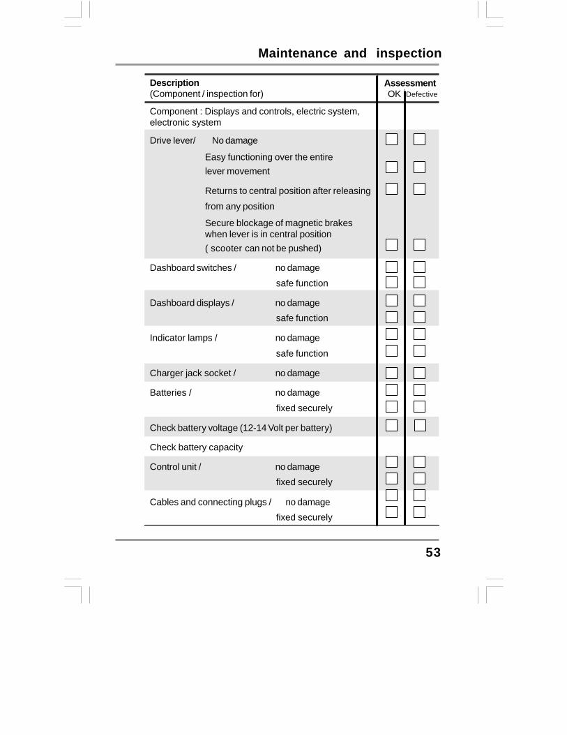
Component : Displays and controls, electric system,electronic system
Drive lever/ No damage
Easy functioning over the entirelever movement
Returns to central position after releasing
from any position
Secure blockage of magnetic brakeswhen lever is in central position( scooter can not be pushed)
Dashboard switches / no damage
safe function
Dashboard displays / no damagesafe function
Indicator lamps / no damage
safe function
Charger jack socket / no damage
Batteries / no damage
fixed securely
Check battery voltage (12-14 Volt per battery)
Check battery capacity
Control unit / no damagefixed securely
Cables and connecting plugs / no damagefixed securely

Maintenance and inspection
16.0 Troubleshooting16.1 Before troubleshooting
Before you start troubleshooting, pleaseobserve the following points to avoidsimple error sources.
Switch off.
Ensure that the main plug (1)and the battery plug(2) for atight fit.
Switch on again.
If the error should occur again, youcan find information abouttroubleshooting and appropriateremedies in the lists in sections 16.2and 16.3.
54
Description(Component / inspection for)
AssessmentOK Defective
Component : Drive
Motor, drive / no damage
fixed securely
drive noise
Motor, magnetic brake / holding force OK(Scooter can not be pushed with engaging lever in drive-position)
Engaging lever / no damage
functions easily
lever engaged(lever remains engaged)

Troubleshooting
16.2 Troubleshooting
55
Fault Cause Remedy
Scooter does not run /no display at the dashboard
Scooter not Switch the scooterswitched on on (chapter 8)
Powersupplyinterrupted
Battery not plugedin
Front unit connectornot plugged in
Check the batteryfuses(chapter 17)
Check fuse inpower supply totiller head(chapter 17)
Batteries Charge thedischarged batteries
(chapter 10)
Batteries Replacebatteries defective (dealer)
Scooter does not run Check battery Charge the batteriescharge display (chapter 10)(battery discharged).
switched Switch to driveto push mode mode (chapter 9)
Drive lever Releasedrive lever pressed while switching onFault on drive Visit your dealerlever
Automatic switch- Switch scooter offoff (overload and switch scooteroff protection) active on again a few
seconds later for theunit to reset.
Operation Check blink codeindicator blinking (chapter 16)

Troubleshooting
battery cable
Batteries
56
Fault Cause Remedy
Main fuses blow frequently Batteries defective
Motor defective
Fault in control Visit your dealerunit
Short-circuit inelectricalequipment
Battery charge display movesrapidly to discharged duringjourney
Motor jerks during driving
Batteries Charge the batteriesdischarged (chapter 10)
Batteries defective
Motor defectiveVisit your dealer
Batteries do not charge Defective fuse inpower supply to Visit your dealertiller head
Defective fuse in Visit your dealer
Front unit Plug in front unitconnector not connectorplugged in (chapter 13)
Battery chargerdefective
Visit your dealer
completelydischarged

Troubleshooting
16.3 Operation indicator blink codesThe operation indicator (1) on the dashboardis also designed as a display for errormessages.Various faults in the drive electronics aredisplayed using blink sequence is as listed.
16.3.1 Blink list
57
Instrument indicatorError code LED indicator Cause
slight blink Auto switch off(scootor stay 10min ),KEY-ON again002,003 8xblink Fault in ECU or wires fall off0203,0204 8xblink Fault in ECU or wires fall off0810 0814~17 7xblink Fault in drive lever, Lever does not reset1000 blinking quickly Charging the scootor, scootor does not run1400 3xblink Fault to motor brake or wires fall off 1500 ~1502 9xblink Fault to motor brake 1600 10xblink Battery voltage too low1705 8xblink Fault in ECU or wires fall off1802 1805 8xblink Fault in ECU or wires fall off1B20 8xblink Fault in ECU or wires fall off1D02 7xblink Fault in drive lever, Lever does not reset
1E03 6xblink Charging the scootor, scootor does not run2102 8xblink Fault in ECU or wires fall off
2C00,2C01 1xblink contiute slowlyBatteries voltage too low2D01 8xblink Fault in ECU or wires fall off3100 3102 8xblink Fault in ECU or wires fall off3210 3213 8xblink Fault in ECU or wires fall off3600~360E 8xblink Fault in ECU or wires fall off3B01 2xblink Motor cable short-circuited4401 8xblink wires fall off7000~7001 4xblink Parking brake off

58
Repairs
17.0 RepairsThe following repair information should enable you to carry out smallrepairs on your vehicle yourself. You should, however, only carry outsuch work if you are used to working with the tools described here sinceit is impossible to fully prevent injury hazards when handling tools. Ifyou are not sure, you should try to get help from a second person ifpossible or contact your dealer.In order to guarantee that all nuts and fixing screws are fitted tightlyafter repairs, you should ensure that these are tightened using thetorque specified.
17.1 Information about safety at workClamping and crushing hazard!Pay particular attention to hazards caused by clamping andcrushing while carrying out any repair work. This appliesparticularly to all rotating and adjustable parts of the scooter suchas around the steering wheels.
The scooter must be lifted in order to carry out certain work such asremoving the wheels. Before you lift the scooter, make sure you prevent it rolling away by
wedging it securely. Make sure the vehicle cannot fall down when raised by using
suitable supports such as wooden blocks. Always place the blocks under metal components such as frames,
drive units.Do not support the scooter by the plastic panelling!
ToolsThe following tools are necessary to carry out therepairs described:
1 x screwdriver; Phillips head No. 21 x screwdriver1 x ring spanner, size 10mm1 x ring spanner; size 12 mm1 x ring spanner; size 14 mm1 x ring spanner; size 17 mm1 x socket spanner, size 19 mm
17.2

59
Repairs
17.3 Wheels - removal and replacementTools required:Front wheel: 1 x socket spanner, size 17 mmRear wheel: 1 x socket spanner, size 19mm
Removing the wheels:
Front wheel
Unscrew the valve cap(1)Loosen the self-locking bolt (2) for thewheel fastening.Secure against rolling away.Lift the scooter and support it
Remove the self-locking bolt for thewheel fastening.Pull the wheel off the stem.
Real wheel
NOTEDo not use force to remove thewheels from the axles.Your specialist dealer has thenecessary special tools.

Repairs
Fitting the front wheelFitting the front wheel:Push the wheel onto the stem (3) as faras the wheel stop.
Screw the wheel fixing self-locking bolt(4) and tighten it (size 17 mm).Lower the scooter.Retighten the self-locking bolt (4).
Fitting the rear wheel: Locating the axle key
Place the key (5) in the slot in the driveshaft (6).
NOTEThe key is rectangular. Placeit with its widest side in theaxle slot.
Fitting the rear wheelPush the wheel onto the stem and alignthe wheel hub groove (7) with the key inthe drive shaft.Push the wheel on as far as the driveshaft stop.
60

Repairs
Locating the washer
Place the washer (8).
Securing the rear wheel
Screw the wheel fixing self-locking bolt(9) and tighten it (size 19mm).Lower the scooter.Retighten the self-locking bolt.
61

17.4 Replacing the wheel
Remove the damaged wheel.(wheel with tyre is one set)
The wheel to be replacedwith a new set
Front wheel
62
Rear wheel

Repairs - fuses
17.5 Fuses Wiring diagram
A wiring diagram with fuse sizes is locatedon the control unit cover.The scooter is fitted with the following fusiblefuses.The fuses are located back the control unitcover.
63
(1)2A fuse= power supply to tiller.
(2)10A fuse= light.
(3)10A fuse= charging socket.
(4)40A fuse= in each battery positive cable
To replace Fuse:(A) Open fuse holder.(B) Pull out fuse and replace it.(C) Close fuse holder.
1 2 3
4

Repairs - batteries
17.6 BatteriesOnly replace the batteries with the following battery types:
12 V / 22 Ah, lead acid deep cycle batteries.
You may not use wet cell batteries with detachable cover caps.
Risk of accidents!• Refitting the battery may only be carried out by your dealer.
17.7.1 Disposal of used or damaged batteries
Caution acid!• Observe safety information in chapter 1
BATTERIES ARE HAZARDOUSWASTE!!Used and defective batteries must be properly disposedof and only handed over to the correct disposal points.
Please give used or damaged batteries back to your dealer.He will ensure that they are properly disposed of.
Handling damaged batteries: When handling damaged batteries or objects which
have been soiled with acid, you must always wear:- protective goggles- acid-proof gloves- respiratory protection
Always wash soiled objects and tools with plenty of water.
Transporting damaged batteries: Always wear protective goggles and acid-proof gloves. Always transport and store batteries in an acid-proof container.
64
Repairs - batteries
65
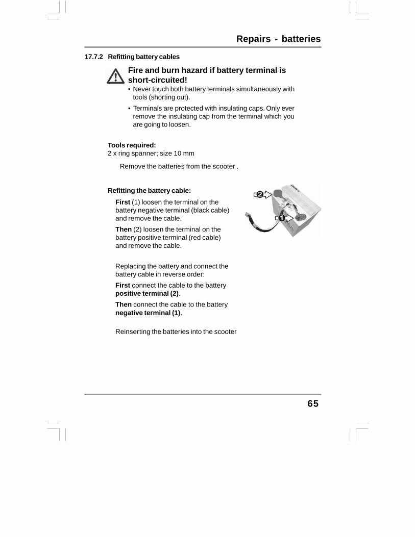
17.7.2 Refitting battery cables
Fire and burn hazard if battery terminal isshort-circuited!• Never touch both battery terminals simultaneously with
tools (shorting out).• Terminals are protected with insulating caps. Only ever
remove the insulating cap from the terminal which youare going to loosen.
Tools required:2 x ring spanner; size 10 mm
� Remove the batteries from the scooter .
Refitting the battery cable:� First (1) loosen the terminal on the
battery negative terminal (black cable)and remove the cable.Then (2) loosen the terminal on thebattery positive terminal (red cable)and remove the cable.
�
� Replacing the battery and connect thebattery cable in reverse order:First connect the cable to the batterypositive terminal (2).Then connect the cable to the batterynegative terminal (1).
� Reinserting the batteries into the scooter

66
Temporary storage
18.0 Temporary storageIf you are not intending to use your scooterfor longer periods (e.g. over the winter, youshould prepare it as follows:
Remove soiling and dust.Charge the batteries completely.Place the scooter on supports. Lift highenough so that the tyres are no longertouching the floor.
Front support
Care during storage:Recharge the batteries once a month(see chapter 10).
Rear support

Appendix - specifications
19.1 Specifications19.1.1 General data
Version ........................................................... Super 8 ForUTurning radius ................................................1560 mmSpeed ............................................................. 9.6 kph (6 mph)Maximum range*…………………............................................... approx. 35km(21miles)Maximum climable incline ............................... 10°
Maximum climable obstacle ........................... 80 mmTotal weight (ready for driving incl. Batteries)....90 kgweight heaviest part ....................................... 26.1 kgMaximum working load (user weight) .............. 160 kg (350lb)
Tyre size ...............................................…….260/85 – 4 (solid tyres)Working voltage (battery voltage) ................... 24 VoltBatteries ......................................................... 12V36AHX2Main fuse ....................................................... 1 x 40 AStorage temperature .......................................- 40°C to + 65°CAmbient temperature ...................................... - 25°C to + 50°CBulbs:Position light .................................................24 Volt / 5 WattRear position light .........................................12 Volt / 5 WattFront indicator ............................................…24 Volt / 10 WattRear indicator ............................................… 24 Volt / 10 Watt
67

Appendix - tightening torques
19.2 Torque for fixing screwsFront wheel central self-locking bolt Rear wheel central self-locking bolt
General torque for nuts and bolts:
= 50 Nm= 60 Nm
M5M6M8M10M12
= 4.5 to 6 Nm= 8 to 12 Nm= 18 to 25 Nm= 30 to 40 Nm= 50 to 60 Nm
19.3 Disposing of the scooterThe scooter consists of metal and plastic components, electroniccomponents, electrical cables and batteries.Disposal of the individual materials must be carried out in accordancewith environmental and disposal regulations in the relevant country, andmay only take place after the scooter has been dismantled.To dismantle the electromobile and to separate and dispose of thematerials, you would be advised to hand it over to your specialist dealer.
Batteries may not be disposed of in domestic waste, and must bedisposed of according to national regulations
68
Warranty
20.0 Warranty informationThe Super 8 ForU Model scooters are warranted for 12 months from date ofpurchase.
Important!• During the warranty period any parts that have become defective due
to faulty workmanship or material will be repaired or replaced withoutcharge by KYMCO HEALTHCARE supplier / dealer.The warranty excludes tyres and all items that have been subjectto undue wear and items subjected to misuse.Unauthorized changes or modifications will forfeit your warranty.If a defect or fault is discovered, KYMCO Healthcare supplier / dealerfrom whom the scooter was purchased should be notified immediately.
•
••
Limitation of liabilityThe warranty does not extend to the consequential costs resulting fromfault clearence, in particular freight and travel costs, loss of earnings,expenses, etc.The manufacturer will not accept responsibility for any damage or injurycaused by misuse or non-observance of the instructions set out in thisuser manual.
69

Work Shop use only-- Replacing the ECU(1)
70
ECU Version:The control unit is a programmable electronic regulating unit. Itregulates drive characteristics such as acceleration, maximumspeed and braking behavior.The drive characteristics can be set to match the user'srequirements by altering the programming.Reprogramming may only be carried out by specialist dealers.

Work Shop use only-- Replacing the ECU(2)
71
Switch the Scooter off. Remove the seat unit. Removing the rear panelling. Remove the lighting cable. Remove ECU protect cover bolts and battery plug and front
connector. Disassemble the battery plugs (+)(-)and (1)(2) as picture-- Disassemble the ECU’s plug as picture-- Remove ECU bolts -- . Disassemble the ECU-- . Installation is in the reverse order of removal. Attached to wire diagram.

Work Shop use only-- Removing andinstalling the motor
72
Switch the Scooter off. Remove the seat unit. Removing the rear panelling. Remove the lighting cable. Remove ECU protect cover bolts and battery plug and front
connector. Disassemble the battery plugs (1)(2) as picture-- Disassemble the ECU’s plug as picture-- Remove the rear wheels. Remove the motor stay bolts as picture.-- Disassemble the electric motor.

Work Shop use only-Adjusting the TOE-IN(1)
73
Step 1: Handlebar- Push the tiller backward into the required position.- Moving the handlebar to the seat as picture- Ensure the handlebar is fixed firmly by seat. If thethrottle levers touch the seat, remove the throttle levers.

Work Shop use only-Adjusting the TOE-IN(2)
74
Step 2: Measure the tyre’s “toe-in”Separately measure the figure between the upper andlower side.For Midi XL, should setting the standard point as picture.
Lower Upper
Standard point
Step 3: Adjusting the longer rod’s figure- For tyre’s “toe-in”, the upper distance should be lessthan the lower one.Standard: Maxi 0~5 mm Midi XL& Midi Super 4/8 0~4 mm Mini & Micro 0~3 mm
To tighten the rod’s nuts after adjusting
Correct
Wrong
Forward

Work Shop use only-Adjusting the TOE-IN(3)
75
Step 4 : Adjusting the shorter rod’s figure- To straighten the front tyres- The steering stem should be centered the body frame byadjusting the shorter rod- The front tyre parallels the steering stem by sight.- Tighten the shorter rod‘s nut after adjusting.

Work Shop use only- SP1 (Diagnostic Tool)introduction(1)
76
Menus:You are in a menu if the display shows a message endingwith” ? “Use the up and down keys to look through the menu.
Use the help key to find out what each menu item does
Press the enter key to use a menu itemOnce you are inside a menu itemUse the help key to find out what to do nextTrying out your settingYou can drive at any time
?
?

Work Shop use only- SP1 (Diagnostic Tool)introduction(2)
77
Using your SP1:Remove the seat unit.Pull the rear panelling off the scooter upwards.Remove diagnosis tool connector protect plug.Plug in the SP1.--Switch on the controller.The SP1 is ready for use.When you finish:Unplug the SP1.The controller is ready to drive.

Work Shop use only-Controller work sheet
78
CONTROLLER PARAMETERS DESIRED SETTINGS RANGE UNITS DESCRIPTIONFAST SLOW
FORWARD ACCELERATION 15 15 0.1 TO 10SFAST / SLOW
FORWARD DECELERATION 3 6 0.1 TO 10SFAST / SLOW
REVERSE ACCELERATION 25 25 0.1 TO 10SFAST / SLOW
REVERSE DECELERATION 8 10 0.1 TO 10SFAST / SLOW
FORWARD SPEED(MAX.) 100 45 0 TO 100%FAST / SLOW
FORWARD SPEED(MIN.) 50 25 0 TO 100%FAST / SLOW
REVERSE SPEED(MAX.) 35 25 0 TO 100%FAST / SLOW
REVERSE SPEED(MIN.) 21 21 0 TO 100%FAST / SLOW
THROTTLE INVERT NO NO/YES See page 35SLEEP TIMER 10 0 TO 20
MINUTES
PARAMETER NO.:36010-LDB4-E500-UKECU :36000-LDB4-E500-UKEQ35CB(UK)
P&G SDRIVE 24 Volt 90AmpCONTROLLER WORKSHEET
NOTE:*Specifications are subject to change without notice.

By KWANG YANG Motor Co., Ltd.First Edition, Jan. 2011
All rights reserved. Any reproduction orunauthorized use without the written permission of
KWANG YANG Motor Co., Ltd.is strictly prohibited.T300-EQ35CB -A1
• NO.35 Wan Hsing Street,San Min District Kaohsiung city, Taiwan,Republic Of China• NO.61,Chung-Shan Sth Rd ,Lu-Chu Village ,KaohsiungCounty,Taiwan, Republic Of China
Date printed:Jan.2011

KWANG YANG MOTOR CO., LTD
No.35 Wan Hsing Street,San Min Distrist
Kaohsiung Taiwan, Republic of China
Telephone:886-7-3822526
FAX : 886-7-3950021
KYMCO Healthcare UK LimitedHeol MostynVillage Farm Industrial EstatePyleBridgendCF33 6BJTEL:01656 670095 FAX:01656 858353www.kymcohealthcare.co.uk
H E A L T H C A R E