Embed Size (px)
Citation preview
SUNX Limited MJE-SF2A No. 0005-44V - 1 -
SUNX Limited MJE-SF2A No. 0005-44V - 2 -
- Memo -
SUNX Limited MJE-SF2A No. 0005-44V - 3 -
Contents Chapter 1 Introduction
1.1 Before Using This Product······························································· 5 1.2 Safety Precautions ·········································································· 5 1.3 Applicable Standards······································································· 7
Chapter 2 General Outline
2.1 Features·························································································· 8 2.2 Part Description··············································································· 8 2.3 Specifications ·················································································· 10 2.4 Dimensions ····················································································· 13
2.4.1 Rear Mounting ···························································································· 13 2.4.2 Side Mounting····························································································· 15
2.5 Functions························································································· 17 2.5.1 Test Input (Self-diagnosis Function)···························································· 17 2.5.2 Emission Halt Function ··············································································· 18 2.5.3 Alarm Output······························································································· 18
2.6 Options···························································································· 19 Chapter 3 Wiring and Mounting
3.1 Protection Area················································································ 22 3.1.1 Sensing Area ······························································································ 22 3.1.2 Safety Distance··························································································· 23 3.1.3 Influence of Reflective Surfaces························································ 26
3.2 Connection Configuration································································ 27 3.2.1 Connection of One Set of Sensor······················································ 27 3.2.2 Sensor Placement······················································································· 27
3.3 Mounting ························································································· 29 3.3.1 Mounting Procedure···················································································· 29 3.3.2 Dimensional Drawing of Mounting Brackets ··············································· 32 3.3.3 Mounting Angle Adjustment Range····························································· 35
3.4 Wiring······························································································ 36 3.4.1 Power Supply Unit ······················································································ 36 3.4.2 Sensor Wiring Diagrams ············································································· 36 3.4.3 Wiring・Connection Procedure ···································································· 37 3.4.4 I/O Circuit Diagrams···················································································· 38
3.5 Adjustment ······················································································ 39 3.5.1 Beam-axis Alignment ·················································································· 39 3.5.2 Operation Test····························································································· 41 3.5.3 Operation ···································································································· 42
SUNX Limited MJE-SF2A No. 0005-44V - 4 -
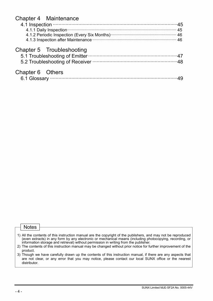
Chapter 4 Maintenance 4.1 Inspection ························································································45
4.1.1 Daily Inspection··························································································· 45 4.1.2 Periodic Inspection (Every Six Months)······················································· 46 4.1.3 Inspection after Maintenance ······································································ 46
Chapter 5 Troubleshooting
5.1 Troubleshooting of Emitter ·······························································47 5.2 Troubleshooting of Receiver ····························································48
Chapter 6 Others
6.1 Glossary ··························································································49
1) All the contents of this instruction manual are the copyright of the publishers, and may not be reproduced
(even extracts) in any form by any electronic or mechanical means (including photocopying, recording, or information storage and retrieval) without permission in writing from the publisher.
2) The contents of this instruction manual may be changed without prior notice for further improvement of the product.
3) Though we have carefully drawn up the contents of this instruction manual, if there are any aspects that are not clear, or any error that you may notice, please contact our local SUNX office or the nearest distributor.
Notes
SUNX Limited MJE-SF2A No. 0005-44V - 5 -
Chapter 1 Introduction 1.1 Before Using This Product
Thank you for purchasing SUNX’s Compact・Global Light Curtain, SF2-A Series (hereinafter called ‘this device’). Please read this instruction manual carefully and thoroughly for the correct and optimum use of this product. Kindly keep this manual in a convenient place for quick reference. This device is a safety light curtain for protecting a person from dangerous parts of a machine which can cause injury or accident. This manual has been written for the following personnel who have undergone suitable training and have knowledge of safety light curtain, as well as, safety systems and standards (ANSI, etc.) • who are responsible for the introduction of this device • who design a system using this device • who install and connect this device • who manage and operate a plant using this device
1.2 Safety Precautions
General Cautions
• Use this device as per its specifications. Do not modify this device since its functions and capabilities may
not be maintained and it may malfunction. • This device has been developed / produced for industrial use only. • Use of this device under the following conditions or environment is not presupposed. Please consult us if
there is no other choice but to use this device in such an environment. 1) Operating this device under conditions and environment not described in this manual. 2) Using this device in the following fields: nuclear power control, railroad, aircraft, automobiles, combustion
facilities, medical systems, aerospace development, etc. • When this device is to be used for enforcing protection of a person from any danger occurring around an
operating machine, the user should satisfy the regulations established by national or regional security committees (Occupational Safety and Health Administration: OSHA, the European Standardization Committee, etc.). Contact the relative organization(s) for details.
• In case of applying this device to particular equipment, follow the safety regulations in regard to appropriate usage, mounting (installation), operation and maintenance. The users, including the installation operator, are responsible for the introduction of this device.
• Use this device by installing suitable protection equipment as a countermeasure for failure, damage, or malfunction of this device.
• Before using this device, check whether the device performs properly with the functions and capabilities as per the design specifications.
• In case of disposal, dispose this device as industrial waste.
SUNX Limited MJE-SF2A No. 0005-44V - 6 -
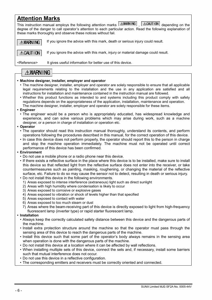
Attention Marks This instruction manual employs the following attention marks , depending on the degree of the danger to call operator’s attention to each particular action. Read the following explanation of these marks thoroughly and observe these notices without fail.
<Reference> It gives useful information for better use of this device.
• Machine designer, installer, employer and operator
• The machine designer, installer, employer and operator are solely responsible to ensure that all applicable legal requirements relating to the installation and the use in any application are satisfied and all instructions for installation and maintenance contained in the instruction manual are followed.
• Whether this product functions as intended to and systems including this product comply with safety regulations depends on the appropriateness of the application, installation, maintenance and operation. The machine designer, installer, employer and operator are solely responsible for these items.
• Engineer • The engineer would be a person who is appropriately educated, has widespread knowledge and
experience, and can solve various problems which may arise during work, such as a machine designer, or a person in charge of installation or operation etc.
• Operator • The operator should read this instruction manual thoroughly, understand its contents, and perform
operations following the procedures described in this manual, for the correct operation of this device. • In case this device does not perform properly, the operator should report this to the person in charge
and stop the machine operation immediately. The machine must not be operated until correct performance of this device has been confirmed.
• Environment • Do not use a mobile phone or a radio phone near this device. • If there exists a reflective surface in the place where this device is to be installed, make sure to install
this device so that reflected light from the reflective surface does not enter into the receiver, or take countermeasures such as painting, masking, roughening, or changing the material of the reflective surface, etc. Failure to do so may cause the sensor not to detect, resulting in death or serious injury.
• Do not install this device in the following environments. 1) Areas exposed to intense interference (extraneous) light such as direct sunlight 2) Areas with high humidity where condensation is likely to occur 3) Areas exposed to corrosive or explosive gases 4) Areas exposed to vibration or shock of levels higher than that specified 5) Areas exposed to contact with water 6) Areas exposed to too much steam or dust 7) Areas where the beam-receiving part of this device is directly exposed to light from high-frequency
fluorescent lamp (inverter type) or rapid starter fluorescent lamp. • Installation
• Always keep the correctly calculated safety distance between this device and the dangerous parts of the machine.
• Install extra protection structure around the machine so that the operator must pass through the sensing area of this device to reach the dangerous parts of the machine.
• Install this device such that some part of the operator’s body always remains in the sensing area when operation is done with the dangerous parts of the machine.
• Do not install this device at a location where it can be affected by wall reflections. • When installing multiple sets of this device, connect the sets and, if necessary, install some barriers
such that mutual interference does not occur. • Do not use this device in a reflective configuration. • The corresponding emitters and receivers must be correctly oriented and connected.
If you ignore the advice with this mark, death or serious injury could result.
If you ignore the advice with this mark, injury or material damage could result.
SUNX Limited MJE-SF2A No. 0005-44V - 7 -
• Equipment in which this device is installed
• Do not use this device in the ‘PSDI Mode’, functioning as the starter of the equipment in which this device is installed.
• This device is the Type 2 electro-sensitive protective equipment that is designed to be used with a system that requires the satisfaction of the requirements of Safety Category (control system safety related categories) 2, 1 or B of European Standard EN 954-1. Never use this device with a system requiring the satisfaction of the requirements of Safety Category 4, such as a press, or Safety Category 3.
• Do not install this device with a machine whose operation cannot be stopped immediately in the middle of an operation cycle by an emergency stop equipment.
• This device starts the performance after 2 seconds from the power ON. Have the control system started to function with this timing.
• Wiring • Make sure that the power supply is off while wiring. • All electrical wiring should conform to the regional electrical regulations and laws. The wiring should
be done by engineer(s) having the special electrical knowledge. • Do not run the sensor cable together with high-voltage lines or power lines or put them together in
the same raceway. • In case of extending the cable of the emitter or the receiver, each can be extended by 20.5m or less.
• Maintenance • When replacement parts are required, always use only genuine supplied replacement parts. If
substitute parts from another manufacturer are used, the sensor may not come to detect, resulting in death or serious body injury.
• The periodical inspection of this device must be performed by an engineer having the special knowledge.
• After maintenance or adjustment, and before starting operation, test this device following the procedure specified in ‘Chapter 4 Maintenance’.
• Clean this device with a clean cloth. Do not use any volatile chemicals. • Others
• Never modify this product. Modification may cause the sensor not to detect, resulting in death or serious body injury.
• Do not use this device to detect objects flying over the detection area. • Do not use this device to detect transparent objects, translucent objects or objects smaller than the
specified min. sensing objects. 1.3 Applicable Standards
This device corresponds to the following standards.
Corresponding Territory Standard No. Authorizing
Organization
Europe (EU) EN 61496-1 (Type 2) IEC 61496-1/2 (Type 2) EN 954-1 (Category 2)
DEMKO
United States of America, Canada
IEC 61496-1/2 (Type 2) UL 61496-1/2 (Type 2) UL 1998
UL
<Reference>
In Canada, the mark has the same validity as the CSA mark. This product conforms to the EMC directive and the Machinery directive. The mark on the sensor main body indicates that this product conforms to the EMC directive.
Never use this device as a safety equipment for any press machine or shearing machine.

SUNX Limited MJE-SF2A No. 0005-44V - 8 -
Chapter 2 General Outline This chapter gives the system construction, part description, dimensions, etc., of this device. 2.1 Features
This device is a light curtain with the following features. • A special controller is not required. • The control output (OSSD) is available in two types, PNP output type and NPN output type. • It has a beam pitch of 20mm (min. sensing object: 30mm) and can have a sensing height from 190mm to
1,950mm, 40mm (min. sensing object: 50mm) and can have a sensing height from 190mm to 1,950mm. • Beam-axis alignment indicators which make beam-axis alignment easy are incorporated. • It incorporates a Test input.
2.2 Part Description
<Reference>
• The indicators of both emitter and receiver are different. • Contents of packing
Sensor SF2-A□(-PN) (-H) Emitter 1 pc. Receiver 1 pc.
Rear sensor mounting bracket MS-SF2N-1 1 set Rear sensor mounting bracket: 4 pcs., Hexagon-socket-head bolt: 8 pcs. U-shaped rear mounting intermediate supporting bracket MS-SF2N-2 (MS-SF4A-H2 for ‘-H’ type) 0 to 5 sets One set consists of U-shaped rear mounting supporting bracket: 2 pcs., Retaining plate: 2 pcs. L-shaped intermediate supporting bracket MS-SF2N-L 0 to 5 sets One set consists of L-shaped intermediate supporting bracket: 2 pcs., Hexagon-socket-head bolt: 2 pcs., Pan head screw: 2 pcs., Nut: 2 pcs. Note: MS-SF2N-2 or MS-SF4A-H2 (U-shaped rear mounting intermediate supporting bracket) and MS-SF2N-L (L-shaped intermediate
supporting bracket) are attached with the following sensors. The number attached is different depending on the sensor as follows. 1 set: SF2-AH36□, SF2-AH40□, SF2-AA18□, SF2-AA20□ 2 sets: SF2-AH48□, SF2-AA24□ 3 sets: SF2-AH56□, SF2-AH64□, SF2-AH72□, SF2-AA28□, SF2-AA32□, SF2-AA36□ 4 sets: SF2-AH80□, SF2-AA40□ 5 sets: SF2-AH88□, SF2-AH96□, SF2-AA44□, SF2-AA48□
Test rod SF2-AH□: SF2-AH-TR (ø 30 220mm)…attached 1 pc. SF2-AA□: SF2-AA-TR (ø 50 220mm)…option Instruction Manual 1 pc.
Beam channel
Display section
U-shaped rear mounting intermediate supporting bracket (Note)
Bottom cap cable
Connector
Emitter
Receiver
Rear sensor mounting bracket
Rear sensor mounting bracket
L-shaped intermediatesupporting bracket (Note)
SUNX Limited MJE-SF2A No. 0005-44V - 9 -
Emitter: It emits light to the receiver facing it. Further, the status of the emitter and the receiver is indicated in its display section.
Receiver: It receives light from the emitter facing it, and turns the control output (OSSD) to ON when light is received from the emitter for all beam channels, and to OFF when light is blocked even for one beam channel.
Further, the receiver status is indicated in its display section. Beam channel: The light emitting elements of the emitter and the light receiving elements of the
receiver are placed at an interval of 20mm (SF2-AH□) or an interval of 40mm (SF2-AA□).
Rear sensor mounting: This bracket is to be used for mounting the emitter/receiver from the rear. It enables the bracket mounting angle to be adjusted. The rear sensor mounting brackets included in the packing
are designed specifically for rear mounting. If side mounting is required, please place an order for the optional side sensor mounting brackets (MS-SF2N-3).
U-shaped rear mounting: These brackets are to be used to attach the sensor with its total length of the sensor intermediate supporting be 36 beams channels or more (SF2-AA□: 18 beams channels or more) to the place bracket where is attached by intense vibration. L-shaped intermediate Please note that the enclosed U-shaped rear intermediate supporting brackets are supporting bracket designed specifically for rear mounting. If side mounting is required, please place an
order for the optional side intermediate supporting brackets (MS-SF2N-4 or MS-SF4A-H4 for ‘-H’ type). The L-shaped intermediate supporting bracket is used for rear mounting and side mounting in common.
<Display Section> Emitter
Receiver
Notes: 1) Since the color of the operation indicator changes according to the ON/OFF state of OSSD, the operation indicator
is marked as OSSD on the sensor. 2) The threshold value where the output turns to ON from OFF is regarded as the incident beam intensity 100%. 3) The description given in [ ] is marked on the sensor.
SUNX Limited MJE-SF2A No. 0005-44V - 10 -
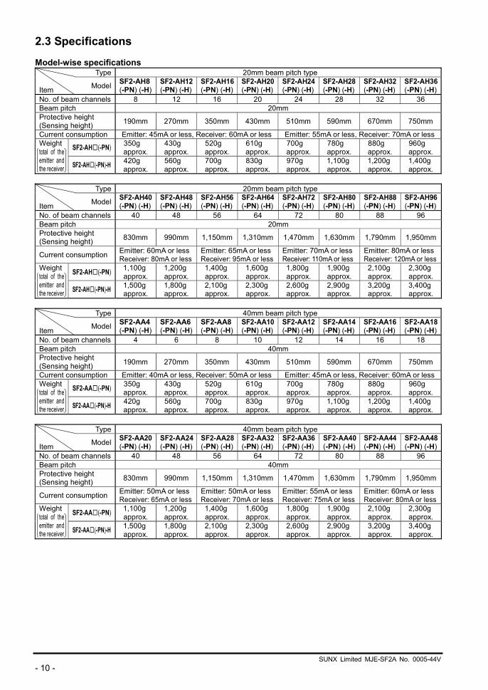
2.3 Specifications Model-wise specifications
Type 20mm beam pitch type Item Model SF2-AH8
(-PN) (-H) SF2-AH12(-PN) (-H)
SF2-AH16(-PN) (-H)
SF2-AH20(-PN) (-H)
SF2-AH24(-PN) (-H)
SF2-AH28(-PN) (-H)
SF2-AH32(-PN) (-H)
SF2-AH36(-PN) (-H)
No. of beam channels 8 12 16 20 24 28 32 36 Beam pitch 20mm Protective height (Sensing height) 190mm 270mm 350mm 430mm 510mm 590mm 670mm 750mm
Current consumption Emitter: 45mA or less, Receiver: 60mA or less Emitter: 55mA or less, Receiver: 70mA or less
SF2-AH□(-PN) 350g approx.
430g approx.
520g approx.
610g approx.
700g approx.
780g approx.
880g approx.
960g approx.
Weight total of the emitter and the receiver SF2-AH□(-PN)-H 420g
approx. 560g approx.
700g approx.
830g approx.
970g approx.
1,100g approx.
1,200g approx.
1,400g approx.
Type 20mm beam pitch type
Item Model SF2-AH40
(-PN) (-H)SF2-AH48(-PN) (-H)
SF2-AH56(-PN) (-H)
SF2-AH64(-PN) (-H)
SF2-AH72(-PN) (-H)
SF2-AH80(-PN) (-H)
SF2-AH88 (-PN) (-H)
SF2-AH96 (-PN) (-H)
No. of beam channels 40 48 56 64 72 80 88 96 Beam pitch 20mm Protective height (Sensing height) 830mm 990mm 1,150mm 1,310mm 1,470mm 1,630mm 1,790mm 1,950mm
Current consumption Emitter: 60mA or lessReceiver: 80mA or less
Emitter: 65mA or lessReceiver: 95mA or less
Emitter: 70mA or lessReceiver: 110mA or less
Emitter: 80mA or lessReceiver: 120mA or less
SF2-AH□(-PN) 1,100g approx.
1,200g approx.
1,400g approx.
1,600g approx.
1,800g approx.
1,900g approx.
2,100g approx.
2,300g approx.
Weight total of the emitter and the receiver SF2-AH□(-PN)-H 1,500g
approx. 1,800g approx.
2,100g approx.
2,300g approx.
2,600g approx.
2,900g approx.
3,200g approx.
3,400g approx.
Type 40mm beam pitch type
Item Model SF2-AA4
(-PN) (-H)SF2-AA6 (-PN) (-H)
SF2-AA8(-PN) (-H)
SF2-AA10(-PN) (-H)
SF2-AA12(-PN) (-H)
SF2-AA14(-PN) (-H)
SF2-AA16(-PN) (-H)
SF2-AA18(-PN) (-H)
No. of beam channels 4 6 8 10 12 14 16 18 Beam pitch 40mm Protective height (Sensing height) 190mm 270mm 350mm 430mm 510mm 590mm 670mm 750mm
Current consumption Emitter: 40mA or less, Receiver: 50mA or less Emitter: 45mA or less, Receiver: 60mA or less
SF2-AA□(-PN) 350g approx.
430g approx.
520g approx.
610g approx.
700g approx.
780g approx.
880g approx.
960g approx.
Weight total of the emitter and the receiver SF2-AA□(-PN)-H 420g
approx. 560g approx.
700g approx.
830g approx.
970g approx.
1,100g approx.
1,200g approx.
1,400g approx.
Type 40mm beam pitch type
Item Model SF2-AA20
(-PN) (-H)SF2-AA24(-PN) (-H)
SF2-AA28(-PN) (-H)
SF2-AA32(-PN) (-H)
SF2-AA36(-PN) (-H)
SF2-AA40(-PN) (-H)
SF2-AA44 (-PN) (-H)
SF2-AA48(-PN) (-H)
No. of beam channels 40 48 56 64 72 80 88 96 Beam pitch 40mm Protective height (Sensing height) 830mm 990mm 1,150mm 1,310mm 1,470mm 1,630mm 1,790mm 1,950mm
Current consumption Emitter: 50mA or lessReceiver: 65mA or less
Emitter: 50mA or lessReceiver: 70mA or less
Emitter: 55mA or lessReceiver: 75mA or less
Emitter: 60mA or lessReceiver: 80mA or less
SF2-AA□(-PN) 1,100g approx.
1,200g approx.
1,400g approx.
1,600g approx.
1,800g approx.
1,900g approx.
2,100g approx.
2,300g approx.
Weight total of the emitter and the receiver SF2-AA□(-PN)-H 1,500g
approx. 1,800g approx.
2,100g approx.
2,300g approx.
2,600g approx.
2,900g approx.
3,200g approx.
3,400g approx.
SUNX Limited MJE-SF2A No. 0005-44V - 11 -
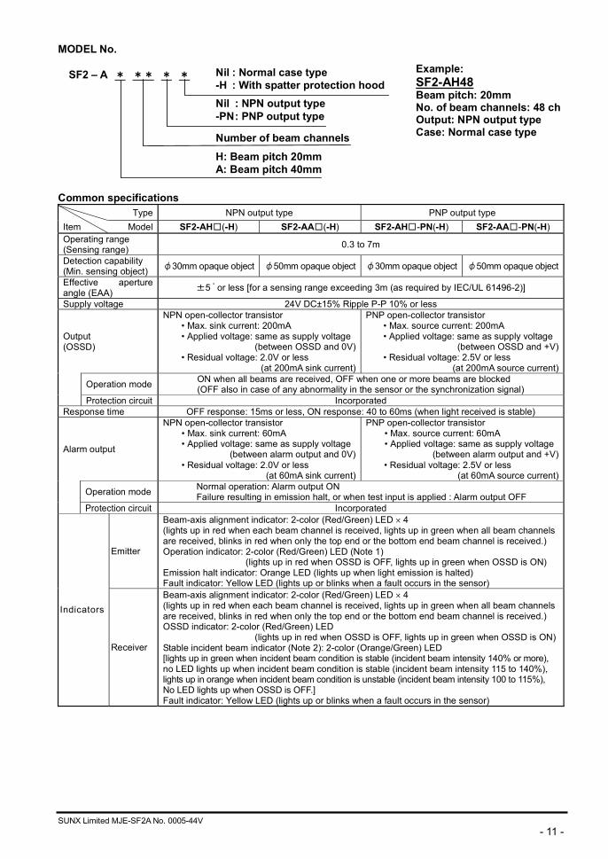
MODEL No. SF2 – A * ** * * Common specifications
Type NPN output type PNP output type Item Model SF2-AH□(-H) SF2-AA□(-H) SF2-AH□-PN(-H) SF2-AA□-PN(-H) Operating range (Sensing range) 0.3 to 7m
Detection capability (Min. sensing object) φ30mm opaque object φ50mm opaque object φ30mm opaque object φ50mm opaque object
Effective aperture angle (EAA) ±5 ゚ or less [for a sensing range exceeding 3m (as required by IEC/UL 61496-2)]
Supply voltage 24V DC±15% Ripple P-P 10% or less
Output (OSSD)
NPN open-collector transistor • Max. sink current: 200mA • Applied voltage: same as supply voltage
(between OSSD and 0V)• Residual voltage: 2.0V or less
(at 200mA sink current)
PNP open-collector transistor • Max. source current: 200mA • Applied voltage: same as supply voltage
(between OSSD and +V) • Residual voltage: 2.5V or less
(at 200mA source current)
Operation mode ON when all beams are received, OFF when one or more beams are blocked (OFF also in case of any abnormality in the sensor or the synchronization signal)
Protection circuit Incorporated Response time OFF response: 15ms or less, ON response: 40 to 60ms (when light received is stable)
Alarm output
NPN open-collector transistor • Max. sink current: 60mA • Applied voltage: same as supply voltage
(between alarm output and 0V)• Residual voltage: 2.0V or less
(at 60mA sink current)
PNP open-collector transistor • Max. source current: 60mA • Applied voltage: same as supply voltage
(between alarm output and +V) • Residual voltage: 2.5V or less
(at 60mA source current)
Operation mode Normal operation: Alarm output ON Failure resulting in emission halt, or when test input is applied : Alarm output OFF
Protection circuit Incorporated
Emitter
Beam-axis alignment indicator: 2-color (Red/Green) LED 4 (lights up in red when each beam channel is received, lights up in green when all beam channels are received, blinks in red when only the top end or the bottom end beam channel is received.) Operation indicator: 2-color (Red/Green) LED (Note 1)
(lights up in red when OSSD is OFF, lights up in green when OSSD is ON) Emission halt indicator: Orange LED (lights up when light emission is halted) Fault indicator: Yellow LED (lights up or blinks when a fault occurs in the sensor)
Indicators
Receiver
Beam-axis alignment indicator: 2-color (Red/Green) LED 4 (lights up in red when each beam channel is received, lights up in green when all beam channels are received, blinks in red when only the top end or the bottom end beam channel is received.) OSSD indicator: 2-color (Red/Green) LED
(lights up in red when OSSD is OFF, lights up in green when OSSD is ON) Stable incident beam indicator (Note 2): 2-color (Orange/Green) LED [lights up in green when incident beam condition is stable (incident beam intensity 140% or more), no LED lights up when incident beam condition is stable (incident beam intensity 115 to 140%), lights up in orange when incident beam condition is unstable (incident beam intensity 100 to 115%), No LED lights up when OSSD is OFF.] Fault indicator: Yellow LED (lights up or blinks when a fault occurs in the sensor)
Example: SF2-AH48 Beam pitch: 20mm No. of beam channels: 48 ch Output: NPN output type Case: Normal case type
Nil : NPN output type-PN : PNP output type
Number of beam channels
H: Beam pitch 20mmA: Beam pitch 40mm
Nil : Normal case type-H : With spatter protection hood
SUNX Limited MJE-SF2A No. 0005-44V - 12 -
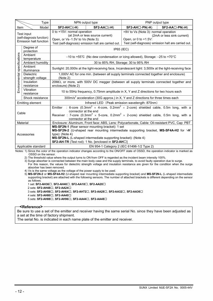
Type NPN output type PNP output type Item Model SF2-AH□(-H) SF2-AA□(-H) SF2-AH□-PN(-H) SF2-AA□-PN(-H)
Test input (self-diagnosis function)Emission halt function
0 to +15V: normal operation (at 2mA or less source current)
Open, or Vs 1.5V to Vs (Note 3): Test (self-diagnosis)・emission halt are carried out.
+9V to Vs (Note 3): normal operation (2mA or less sink current)
Open, or 0 to +1.5V: Test (self-diagnosis)・emission halt are carried out.
Degree of protection IP65 (IEC)
Ambient temperature 10 to +55℃ (No dew condensation or icing allowed), Storage: 25 to +70°C
Ambient humidity 30 to 85% RH, Storage: 30 to 95% RH Ambient illuminance Sunlight: 20,000lx at the light-receiving face, Incandescent light: 3,500lx at the light-receiving face
Dielectric strength voltage
1,000V AC for one min. (between all supply terminals connected together and enclosure) (Note 2)
Insulation resistance
20M , or more, with 500V DC megger (between all supply terminals connected together and enclosure) (Note 2)
Vibration resistance 10 to 55Hz frequency, 0.75mm amplitude in X, Y and Z directions for two hours each En
viro
nmen
tal s
peci
ficat
ions
Shock resistance 300m/s2 acceleration (30G approx.) in X, Y and Z directions for three times each Emitting element Infrared LED (Peak emission wavelength: 870nm)
Cable
Emitter : 6-core (0.3mm2 4-core, 0.2mm2 2-core) shielded cable, 0.5m long, with a connector at the end
Receiver : 7-core (0.3mm2 5-core, 0.2mm2 2-core) shielded cable, 0.5m long, with a connector at the end
Material Enclosure: Aluminum, Front face: ABS, Lens: Polycarbonate, Cable: Oil-resistant PVC, Cap: PBT
Accessories
MS-SF2N-1 (Rear sensor mounting bracket): 1 set MS-SF2N-2 (U-shaped rear mounting intermediate supporting bracket, MS-SF4A-H2 for ‘-H’ type): (Note 4) MS-SF2N-L (L-shaped intermediate supporting bracket): (Note 4) SF2-AH-TR (Test rod): 1 No. [enclosed in SF2-AH□]
Applicable standard EN 954-1 Category 2 (IEC 61496-1/2 Type 2) Notes: 1) Since the color of the operation indicator changes according to the ON/OFF state of OSSD, the operation indicator is marked as
OSSD on the sensor. 2) The threshold value where the output turns to ON from OFF is regarded as the incident beam intensity 100%. 3) Surge absorber is connected between the main body case and the supply terminals, to avoid faulty operation due to surge.
For this reason, the values for dielectric strength voltage and insulation resistance are given for the condition when the surge absorber has been removed.
4) Vs is the same voltage as the voltage of the power supply to be used. 5) MS-SF2N-2 or MS-SF4A-H2 (U-shaped rear mounting intermediate supporting bracket) and MS-SF2N-L (L-shaped intermediate
supporting bracket) are attached with the following sensors. The number of attached brackets is different depending on the sensor as follows. 1 set: SF2-AH36□, SF2-AH40□, SF2-AA18□, SF2-AA20□ 2 sets: SF2-AH48□, SF2-AA24□ 3 sets: SF2-AH56□, SF2-AH64□, SF2-AH72□, SF2-AA28□, SF2-AA32□, SF2-AA36□ 4 sets: SF2-AH80□, SF2-AA40□ 5 sets: SF2-AH88□, SF2-AH96□, SF2-AA44□, SF2-AA48□
<Reference> Be sure to use a set of the emitter and receiver having the same serial No. since they have been adjusted as a set at the time of factory shipment. The serial No. is indicated in each name plate of the emitter and receiver.
SUNX Limited MJE-SF2A No. 0005-44V - 13 -
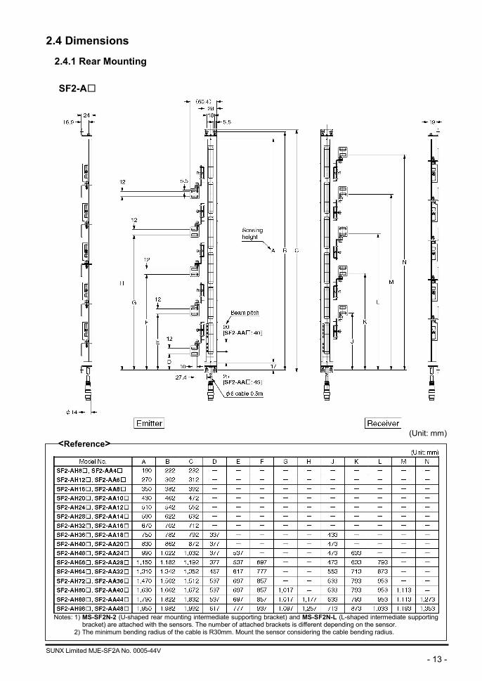
2.4 Dimensions
2.4.1 Rear Mounting
SF2-A□
(Unit: mm)
<Reference>
Notes: 1) MS-SF2N-2 (U-shaped rear mounting intermediate supporting bracket) and MS-SF2N-L (L-shaped intermediate supporting
bracket) are attached with the sensors. The number of attached brackets is different depending on the sensor. 2) The minimum bending radius of the cable is R30mm. Mount the sensor considering the cable bending radius.
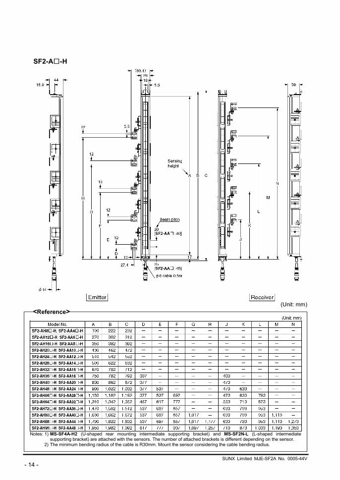
SUNX Limited MJE-SF2A No. 0005-44V - 14 -
SF2-A□-H
(Unit: mm)
<Reference>
Notes: 1) MS-SF4A-H2 (U-shaped rear mounting intermediate supporting bracket) and MS-SF2N-L (L-shaped intermediate
supporting bracket) are attached with the sensors. The number of attached brackets is different depending on the sensor. 2) The minimum bending radius of the cable is R30mm. Mount the sensor considering the cable bending radius.
SUNX Limited MJE-SF2A No. 6060-03 - 15 -
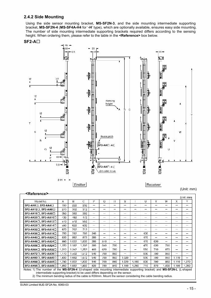
2.4.2 Side Mounting Using the side sensor mounting bracket, MS-SF2N-3, and the side mounting intermediate supporting bracket, MS-SF2N-4 (MS-SF4A-H4 for ‘-H’ type), which are optionally available, ensures easy side mounting. The number of side mounting intermediate supporting brackets required differs according to the sensing height. When ordering them, please refer to the table in the <Reference> box below.
SF2-A□
(Unit: mm)
<Reference>
Notes: 1) The number of the MS-SF2N-4 (U-shaped side mounting intermediate supporting bracket) and MS-SF2N-L (L-shaped
intermediate supporting bracket) to be used differs depending on the sensor. 2) The minimum bending radius of the cable is R30mm. Mount the sensor considering the cable bending radius.

SUNX Limited MJE-SF2A No. 6060-03 - 16 -
SF2-A□-H
(Unit: mm)
<Reference>
Notes: 1) The number of the MS-SF4A-H4 (U-shaped side mounting intermediate supporting bracket) and MS-SF2N-L (L-shaped
intermediate supporting bracket) to be used differs depending on the sensor. 2) The minimum bending radius of the cable is R30mm. Mount the sensor considering the cable bending radius.
SUNX Limited MJE-SF2A No. 0005-44V - 17 -
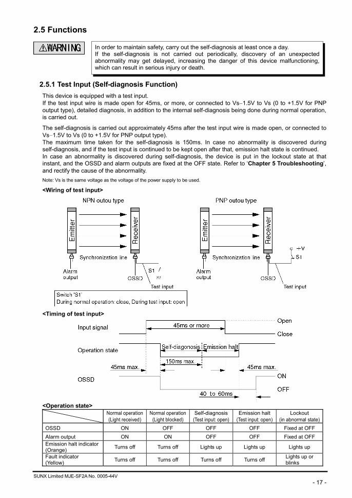
2.5 Functions
2.5.1 Test Input (Self-diagnosis Function) This device is equipped with a test input. If the test input wire is made open for 45ms, or more, or connected to Vs 1.5V to Vs (0 to +1.5V for PNP output type), detailed diagnosis, in addition to the internal self-diagnosis being done during normal operation, is carried out.
The self-diagnosis is carried out approximately 45ms after the test input wire is made open, or connected to Vs 1.5V to Vs (0 to +1.5V for PNP output type). The maximum time taken for the self-diagnosis is 150ms. In case no abnormality is discovered during self-diagnosis, and if the test input is continued to be kept open after that, emission halt state is continued. In case an abnormality is discovered during self-diagnosis, the device is put in the lockout state at that instant, and the OSSD and alarm outputs are fixed at the OFF state. Refer to ‘Chapter 5 Troubleshooting’, and rectify the cause of the abnormality. Note: Vs is the same voltage as the voltage of the power supply to be used.
<Wiring of test input>
<Timing of test input>
<Operation state>
Normal operation(Light received)
Normal operation(Light blocked)
Self-diagnosis(Test input: open)
Emission halt (Test input: open)
Lockout (in abnormal state)
OSSD ON OFF OFF OFF Fixed at OFF Alarm output ON ON OFF OFF Fixed at OFF Emission halt indicator(Orange) Turns off Turns off Lights up Lights up Lights up
Fault indicator (Yellow) Turns off Turns off Turns off Turns off Lights up or
blinks
In order to maintain safety, carry out the self-diagnosis at least once a day. If the self-diagnosis is not carried out periodically, discovery of an unexpectedabnormality may get delayed, increasing the danger of this device malfunctioning,which can result in serious injury or death.
SUNX Limited MJE-SF2A No. 0005-44V - 18 -
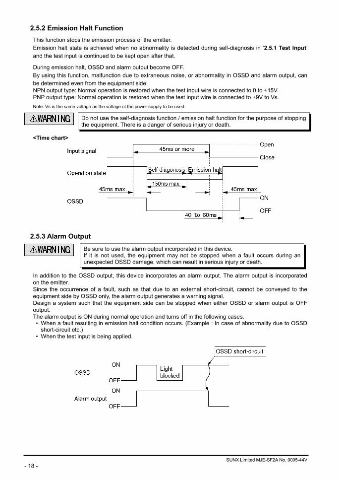
2.5.2 Emission Halt Function This function stops the emission process of the emitter. Emission halt state is achieved when no abnormality is detected during self-diagnosis in ‘2.5.1 Test Input’ and the test input is continued to be kept open after that.
During emission halt, OSSD and alarm output become OFF. By using this function, malfunction due to extraneous noise, or abnormality in OSSD and alarm output, can be determined even from the equipment side. NPN output type: Normal operation is restored when the test input wire is connected to 0 to +15V. PNP output type: Normal operation is restored when the test input wire is connected to +9V to Vs. Note: Vs is the same voltage as the voltage of the power supply to be used.
<Time chart>
2.5.3 Alarm Output
In addition to the OSSD output, this device incorporates an alarm output. The alarm output is incorporated on the emitter. Since the occurrence of a fault, such as that due to an external short-circuit, cannot be conveyed to the equipment side by OSSD only, the alarm output generates a warning signal. Design a system such that the equipment side can be stopped when either OSSD or alarm output is OFF output. The alarm output is ON during normal operation and turns off in the following cases. • When a fault resulting in emission halt condition occurs. (Example : In case of abnormality due to OSSD
short-circuit etc.) • When the test input is being applied.
Do not use the self-diagnosis function / emission halt function for the purpose of stopping the equipment. There is a danger of serious injury or death.
Be sure to use the alarm output incorporated in this device. If it is not used, the equipment may not be stopped when a fault occurs during anunexpected OSSD damage, which can result in serious injury or death.
SUNX Limited MJE-SF2A No. 0005-44V - 19 -
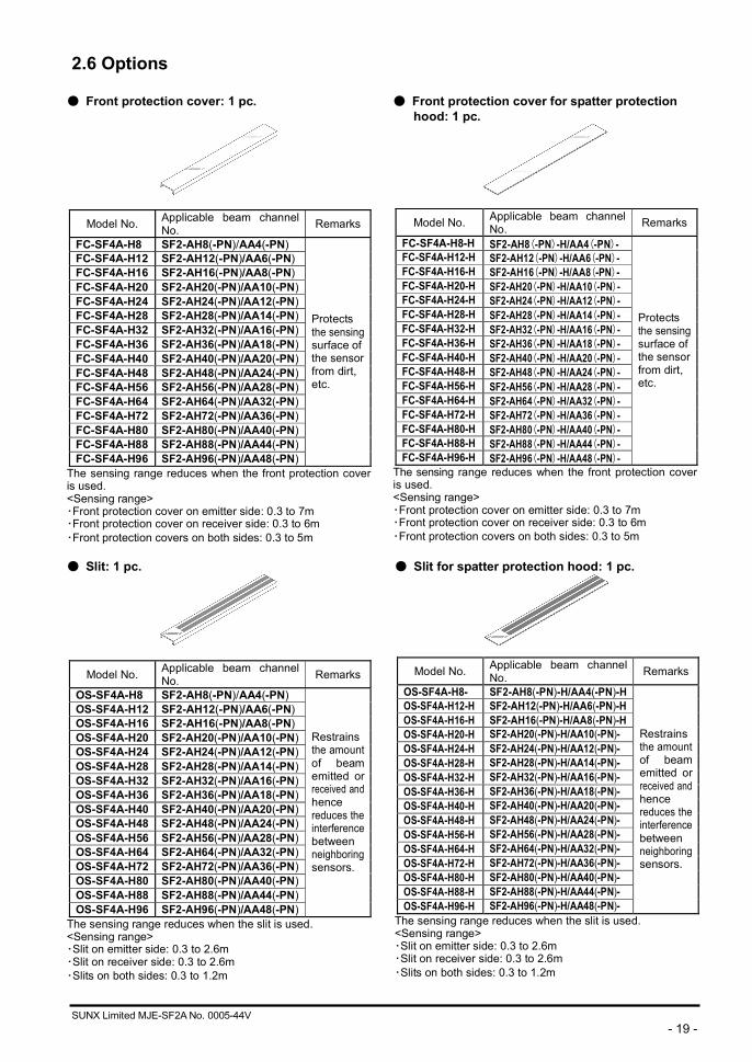
2.6 Options
● Front protection cover: 1 pc.
Model No. Applicable beam channel No. Remarks
FC-SF4A-H8 SF2-AH8(-PN)/AA4(-PN) FC-SF4A-H12 SF2-AH12(-PN)/AA6(-PN)FC-SF4A-H16 SF2-AH16(-PN)/AA8(-PN)FC-SF4A-H20 SF2-AH20(-PN)/AA10(-PN)FC-SF4A-H24 SF2-AH24(-PN)/AA12(-PN)FC-SF4A-H28 SF2-AH28(-PN)/AA14(-PN)FC-SF4A-H32 SF2-AH32(-PN)/AA16(-PN)FC-SF4A-H36 SF2-AH36(-PN)/AA18(-PN) FC-SF4A-H40 SF2-AH40(-PN)/AA20(-PN)FC-SF4A-H48 SF2-AH48(-PN)/AA24(-PN)FC-SF4A-H56 SF2-AH56(-PN)/AA28(-PN)FC-SF4A-H64 SF2-AH64(-PN)/AA32(-PN)FC-SF4A-H72 SF2-AH72(-PN)/AA36(-PN)FC-SF4A-H80 SF2-AH80(-PN)/AA40(-PN)FC-SF4A-H88 SF2-AH88(-PN)/AA44(-PN)FC-SF4A-H96 SF2-AH96(-PN)/AA48(-PN)
Protects the sensing surface of the sensor from dirt, etc.
The sensing range reduces when the front protection cover is used. <Sensing range> ・Front protection cover on emitter side: 0.3 to 7m ・Front protection cover on receiver side: 0.3 to 6m ・Front protection covers on both sides: 0.3 to 5m
● Front protection cover for spatter protection hood: 1 pc.
Model No. Applicable beam channel No. Remarks
FC-SF4A-H8-H SF2-AH8(-PN)-H/AA4(-PN)-FC-SF4A-H12-H SF2-AH12(-PN)-H/AA6(-PN)-FC-SF4A-H16-H SF2-AH16(-PN)-H/AA8(-PN)-FC-SF4A-H20-H SF2-AH20(-PN)-H/AA10(-PN)-FC-SF4A-H24-H SF2-AH24(-PN)-H/AA12(-PN)-FC-SF4A-H28-H SF2-AH28(-PN)-H/AA14(-PN)-FC-SF4A-H32-H SF2-AH32(-PN)-H/AA16(-PN)-FC-SF4A-H36-H SF2-AH36(-PN)-H/AA18(-PN)-FC-SF4A-H40-H SF2-AH40(-PN)-H/AA20(-PN)-FC-SF4A-H48-H SF2-AH48(-PN)-H/AA24(-PN)-FC-SF4A-H56-H SF2-AH56(-PN)-H/AA28(-PN)-FC-SF4A-H64-H SF2-AH64(-PN)-H/AA32(-PN)-FC-SF4A-H72-H SF2-AH72(-PN)-H/AA36(-PN)-FC-SF4A-H80-H SF2-AH80(-PN)-H/AA40(-PN)-FC-SF4A-H88-H SF2-AH88(-PN)-H/AA44(-PN)-FC-SF4A-H96-H SF2-AH96(-PN)-H/AA48(-PN)-
Protects the sensing surface of the sensor from dirt, etc.
The sensing range reduces when the front protection cover is used. <Sensing range> ・Front protection cover on emitter side: 0.3 to 7m ・Front protection cover on receiver side: 0.3 to 6m ・Front protection covers on both sides: 0.3 to 5m
● Slit: 1 pc.
Model No. Applicable beam channel No. Remarks
OS-SF4A-H8 SF2-AH8(-PN)/AA4(-PN) OS-SF4A-H12 SF2-AH12(-PN)/AA6(-PN)OS-SF4A-H16 SF2-AH16(-PN)/AA8(-PN)OS-SF4A-H20 SF2-AH20(-PN)/AA10(-PN)OS-SF4A-H24 SF2-AH24(-PN)/AA12(-PN)OS-SF4A-H28 SF2-AH28(-PN)/AA14(-PN) OS-SF4A-H32 SF2-AH32(-PN)/AA16(-PN)OS-SF4A-H36 SF2-AH36(-PN)/AA18(-PN)OS-SF4A-H40 SF2-AH40(-PN)/AA20(-PN)OS-SF4A-H48 SF2-AH48(-PN)/AA24(-PN)OS-SF4A-H56 SF2-AH56(-PN)/AA28(-PN)OS-SF4A-H64 SF2-AH64(-PN)/AA32(-PN)OS-SF4A-H72 SF2-AH72(-PN)/AA36(-PN)OS-SF4A-H80 SF2-AH80(-PN)/AA40(-PN)OS-SF4A-H88 SF2-AH88(-PN)/AA44(-PN) OS-SF4A-H96 SF2-AH96(-PN)/AA48(-PN)
Restrains the amount of beam emitted or received and hence reduces the interference between neighboring sensors.
The sensing range reduces when the slit is used. <Sensing range> ・Slit on emitter side: 0.3 to 2.6m ・Slit on receiver side: 0.3 to 2.6m ・Slits on both sides: 0.3 to 1.2m
● Slit for spatter protection hood: 1 pc.
Model No. Applicable beam channel No. Remarks
OS-SF4A-H8- SF2-AH8(-PN)-H/AA4(-PN)-H OS-SF4A-H12-H SF2-AH12(-PN)-H/AA6(-PN)-HOS-SF4A-H16-H SF2-AH16(-PN)-H/AA8(-PN)-HOS-SF4A-H20-H SF2-AH20(-PN)-H/AA10(-PN)-OS-SF4A-H24-H SF2-AH24(-PN)-H/AA12(-PN)-OS-SF4A-H28-H SF2-AH28(-PN)-H/AA14(-PN)-OS-SF4A-H32-H SF2-AH32(-PN)-H/AA16(-PN)-OS-SF4A-H36-H SF2-AH36(-PN)-H/AA18(-PN)-OS-SF4A-H40-H SF2-AH40(-PN)-H/AA20(-PN)-OS-SF4A-H48-H SF2-AH48(-PN)-H/AA24(-PN)-OS-SF4A-H56-H SF2-AH56(-PN)-H/AA28(-PN)-OS-SF4A-H64-H SF2-AH64(-PN)-H/AA32(-PN)-OS-SF4A-H72-H SF2-AH72(-PN)-H/AA36(-PN)-OS-SF4A-H80-H SF2-AH80(-PN)-H/AA40(-PN)-OS-SF4A-H88-H SF2-AH88(-PN)-H/AA44(-PN)-OS-SF4A-H96-H SF2-AH96(-PN)-H/AA48(-PN)-
Restrains the amount of beam emitted or received and hence reduces the interference between neighboring sensors.
The sensing range reduces when the slit is used. <Sensing range> ・Slit on emitter side: 0.3 to 2.6m ・Slit on receiver side: 0.3 to 2.6m ・Slits on both sides: 0.3 to 1.2m

SUNX Limited MJE-SF2A No. 0005-44V - 20 -
● Mating cable with connector on one end: 2 pcs./set [1 pc. for emitter (connector: gray), 1 pc. for receiver (connector: black)]
Model No. Cable length Remarks
SF2N-CC3 3m
SF2N-CC7 7m
SF2N-CC10 10m
There is a connector on one end of the cable and separate wires protrude from the other end. The latter are used for wiring. For emitter: 6-core shielded cable For receiver: 7-core shielded cable With connector on one end
● Extension cable with connector on both ends: 2 pcs./set
[1 pc. for emitter (connector: gray), 1 pc. for receiver (connector: black)]
Model No. Cable length Remarks
SF2N-CCJ10 10m
Each end of the cable is equipped with a connector. This cable is used for cable extension. For emitter: 6-core shielded cable For receiver: 7-core shielded cable With connector on both ends
● Side sensor mounting bracket: 4 pcs./set
● U-shaped side mounting intermediate supporting bracket: 2 pcs./set
[U-shaped side mounting supporting bracket, retaining plate, 2 pcs. each]
● L-shaped intermediate supporting bracket: 2 pcs./set
Model No. Remarks MS-SF2N-3 Used for side mounting of sensors.
Model No. Remarks MS-SF2N-4 SF2-AH□/AA□ MS-SF4A-H4 SF2-AH□-H/AA□-H
Used to hold the sensor at the intermediate position for side mounting.
Note: When installing this device having (SF2-AH□: 36 beam channels or more, SF2-AA□: 18 beam channels or more) at places where vibration is intense, use the necessary number of intermediate supporting brackets at the specified positions. 1 set: SF2-AH36□, SF2-AH40□, SF2-AA18□, SF2-AA20□ 2 sets: SF2-AH48□, SF2-AA24□ 3 sets: SF2-AH56□, SF2-AH64□, SF2-AH72□, SF2-AA28□, SF2-AA32□, SF2-AA36□ 4 sets: SF2-AH80□, SF2-AA40□ 5 sets: SF2-AH88□, SF2-AH96□, SF2-AA44□, SF2-AA48□
Model No. Remarks
MS-SF2N-L Used to install the U-shaped rear (side) mounting intermediate supporting bracket on the wall side, etc.
Notes: 1) The same quantity of the intermediate supporting bracket as the U-shaped side mounting intermediate supporting bracket is required. 1 set: SF2-AH36□, SF2-AH40□, SF2-AA18□, SF2-AA20□ 2 sets: SF2-AH48□, SF2-AA24□ 3 sets: SF2-AH56□, SF2-AH64□, SF2-AH72□, SF2-AA28□, SF2-AA32□, SF2-AA36□ 4 sets: SF2-AH80□, SF2-AA40□ 5 sets: SF2-AH88□, SF2-AH96□, SF2-AA44□, SF2-AA48□
2) Since L-shaped intermediate supporting bracket is common for rear mounting and side mounting, in case of side mounting of sensor, the enclosed MS-SF2N-L can be used.
M4 (length 10mm)hexagon-socket-head bolt: 2pcs., M3 (length 10 mm), panhead screw: 2 pcs., Nut: 2 pcs
SUNX Limited MJE-SF2A No. 0005-44V - 21 -
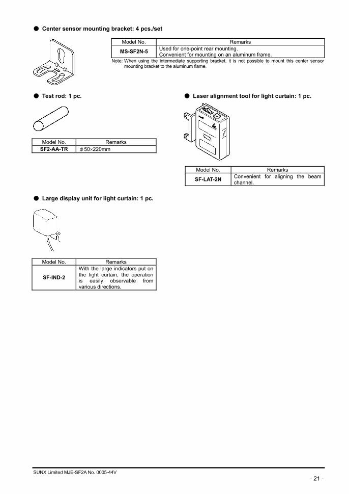
● Center sensor mounting bracket: 4 pcs./set
● Test rod: 1 pc. ● Laser alignment tool for light curtain: 1 pc.
Model No. Remarks SF2-AA-TR φ50 220mm
● Large display unit for light curtain: 1 pc.
Model No. Remarks
SF-IND-2 With the large indicators put on the light curtain, the operation is easily observable from various directions.
Model No. Remarks
MS-SF2N-5 Used for one-point rear mounting. Convenient for mounting on an aluminum frame.
Note: When using the intermediate supporting bracket, it is not possible to mount this center sensor mounting bracket to the aluminum flame.
Model No. Remarks
SF-LAT-2N Convenient for aligning the beam channel.
SUNX Limited MJE-SF2A No. 0005-44V - 22 -
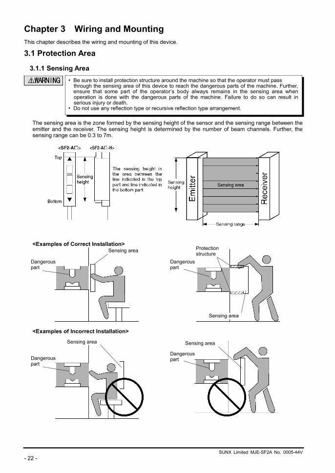
Chapter 3 Wiring and Mounting This chapter describes the wiring and mounting of this device. 3.1 Protection Area
3.1.1 Sensing Area
The sensing area is the zone formed by the sensing height of the sensor and the sensing range between the emitter and the receiver. The sensing height is determined by the number of beam channels. Further, the sensing range can be 0.3 to 7m.
<Examples of Correct Installation>
<Examples of Incorrect Installation>
Sensing area
Dangerous part
Protection structure
• Be sure to install protection structure around the machine so that the operator must pass through the sensing area of this device to reach the dangerous parts of the machine. Further,ensure that some part of the operator’s body always remains in the sensing area when operation is done with the dangerous parts of the machine. Failure to do so can result in serious injury or death.
• Do not use any reflection type or recursive reflection type arrangement.
Dangerous part
Sensing area
Sensing area Sensing area
Dangerous part
Dangerous part
SUNX Limited MJE-SF2A No. 0005-44V - 23 -
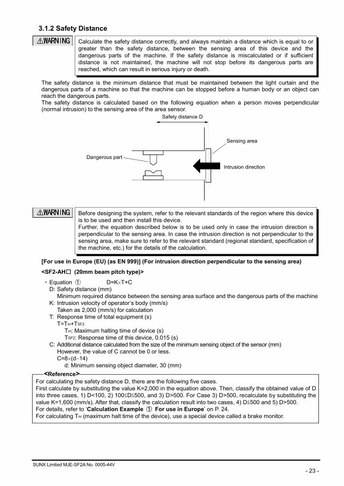
3.1.2 Safety Distance
The safety distance is the minimum distance that must be maintained between the light curtain and the dangerous parts of a machine so that the machine can be stopped before a human body or an object can reach the dangerous parts. The safety distance is calculated based on the following equation when a person moves perpendicular (normal intrusion) to the sensing area of the area sensor.
[For use in Europe (EU) (as EN 999)] (For intrusion direction perpendicular to the sensing area)
<SF2-AH□ (20mm beam pitch type)>
・ Equation ① D=K T+C D: Safety distance (mm)
Minimum required distance between the sensing area surface and the dangerous parts of the machine K: Intrusion velocity of operator’s body (mm/s)
Taken as 2,000 (mm/s) for calculation T: Response time of total equipment (s)
T=Tm+TSF2 Tm: Maximum halting time of device (s) TSF2: Response time of this device, 0.015 (s)
C: Additional distance calculated from the size of the minimum sensing object of the sensor (mm) However, the value of C cannot be 0 or less. C=8 (d 14)
d: Minimum sensing object diameter, 30 (mm) <Reference>
For calculating the safety distance D, there are the following five cases. First calculate by substituting the value K=2,000 in the equation above. Then, classify the obtained value of D into three cases, 1) D<100, 2) 100 D 500, and 3) D>500. For Case 3) D>500, recalculate by substituting the value K=1,600 (mm/s). After that, classify the calculation result into two cases, 4) D 500 and 5) D>500. For details, refer to ‘Calculation Example ① For use in Europe’ on P. 24. For calculating Tm (maximum halt time of the device), use a special device called a brake monitor.
Sensing area
Dangerous part
Safety distance D
Intrusion direction
Calculate the safety distance correctly, and always maintain a distance which is equal to or greater than the safety distance, between the sensing area of this device and the dangerous parts of the machine. If the safety distance is miscalculated or if sufficient distance is not maintained, the machine will not stop before its dangerous parts are reached, which can result in serious injury or death.
Before designing the system, refer to the relevant standards of the region where this device is to be used and then install this device. Further, the equation described below is to be used only in case the intrusion direction is perpendicular to the sensing area. In case the intrusion direction is not perpendicular to the sensing area, make sure to refer to the relevant standard (regional standard, specification of the machine, etc.) for the details of the calculation.
SUNX Limited MJE-SF2A No. 0005-44V - 24 -
<SF2-AA□ (40mm beam pitch type)> ・ Equation ② D=K T+C
D: Safety distance (mm) Minimum required distance between the sensing area surface and the dangerous parts of the machine
K: Intrusion velocity of operator’s body (mm/s) Taken as 1,600 (mm/s) for calculation
T: Response time of total equipment (s) T=Tm+TSF2
Tm: Maximum halting time of device (s) TSF2: Response time of this device, 0.015 (s)
C: Additional distance calculated from the size of the minimum sensing object of the sensor (mm) C=850 (mm)
<Reference> For calculating Tm (maximum halt time of the device), use a special device called a brake monitor.
Calculation Example ① For use in Europe <In case of SF2-AH□ (20mm beam pitch type) (d=30mm)>
First calculate with K=2,000. D =K T+C
=K (Tm+TSF2)+8 (d 14) =2,000 (Tm+0.015)+8 (30 14) =2,000 Tm+2,000 0.015+8 16 =2,000 Tm+158
1) In case D<100 (mm)
Safety distance D is taken as 100 (mm) 2) In case 100 D 500 (mm)
Safety distance D is taken as 2,000 Tm+158 (mm) 3) In case D>500 (mm)
Calculate with K’=1,600. D =K’ (Tm+TSF2)+8 (d 14)
=1,600 (Tm+0.015)+8 (30 14) =1,600 Tm+1,600 0.015+8 16 =1,600 Tm+152
then, calculate again
If the result is: 4) In case D 500 (mm)
Safety distance D is taken as 500 (mm) 5) In case D>500 (mm)
Safety distance D is taken as 1,600 Tm+152 (mm)
In case this device is installed in a system with a maximum halting time of 0.1 (s) D =2,000 Tm+158
=2,000×0.1+158 =358
Since this value matches with Case 2) above, D is 358 (mm).
In case this device is installed in a system with a maximum halting time of 0.3 (s) D =2,000 Tm+158
=2,000 0.3+158 =758
Since this value matches with Case 3) above, D =1,600 Tm+152
=1,600 0.3+152 =632
Since this value matches with Case 5) above, D is 632 (mm).
SUNX Limited MJE-SF2A No. 0005-44V - 25 -
[For use in the United States of America (as ANSI B11.19)] ・ Equation ③ D=K (TS+TC+TSF2+Tbm)+Dpf
D : Safety distance (mm) Minimum required distance between the sensing area surface and the dangerous parts of the machine
K : Intrusion speed {Recommended value in OSHA is 63 (inch/s) [ 1,600 (mm/s)]} ANSI B11.19 does not define intrusion speed (K). When determining K, consider possible factors including physical ability of operators.
TS : Halting time calculated from the operation time of the control element (air valve, etc.) (s)
TC : Maximum response time of the control circuit required for functioning the brake (s)
TSF2 : Response time of this device, 0.015 (s) Tbm : Additional halting time tolerance for the brake monitor (s)
The following equation holds when the machine is equipped with a break monitor. Tbm=Ta (TS+TC)
Ta : Setting time of brake monitor (s) When the machine is not equipped with a break monitor, it is recommended that 20%, or more, of (TS+TC) is taken as additional halting time.
Dpf : Additional distance calculated from the size of the minimum sensing object of the sensor. (mm) SF2-AH□ Dpf=78.2mm SF2-AA□ Dpf=146.2mm
Dpf=3.4 (d-0.276) (inch)
=3.4 (d-7) (mm) d: Minimum sensing object diameter 1.2 (inch) 30 (mm) SF2-AH□
Minimum sensing object diameter 2.0 (inch) 50 (mm) SF2-AA□ Note that the value of Dpf cannot be 0 or less.
<Reference> Since the calculation above is performed by taking 1 (inch)=25.4 (mm), there is a slight difference between the representation in (mm) and that in (inch). Refer to the relevant standard for the details.
Calculation Example ②
<In case of SF2-AH□ (20mm beam pitch type) (d=30mm 1.2inch)>
D =K (TS+TC+TSF2+Tbm)+Dpf =63 (Ta+0.015)+3.4 (d 0.276) (inch) =63 (Ta+0.015)+3.4 (1.2 0.276) =63 Ta+63 0.015+3.4 0.924 =63 Ta+4.0866 (inch) 63 Ta+4.09 (inch)
In case this device is installed in a system with a maximum halting time of 0.1 (s)
D =63 Ta+4.09 =63 0.1+4.09 =10.39
Hence, as per the calculations D is 10.39 (inch) 263.91 (mm).
<Reference> Since the calculation above is performed by taking 1 (inch)=25.4 (mm), there is a slight difference between the representation in (mm) and that in (inch). Refer to the relevant standard for the details.
SUNX Limited MJE-SF2A No. 0005-44V - 26 -
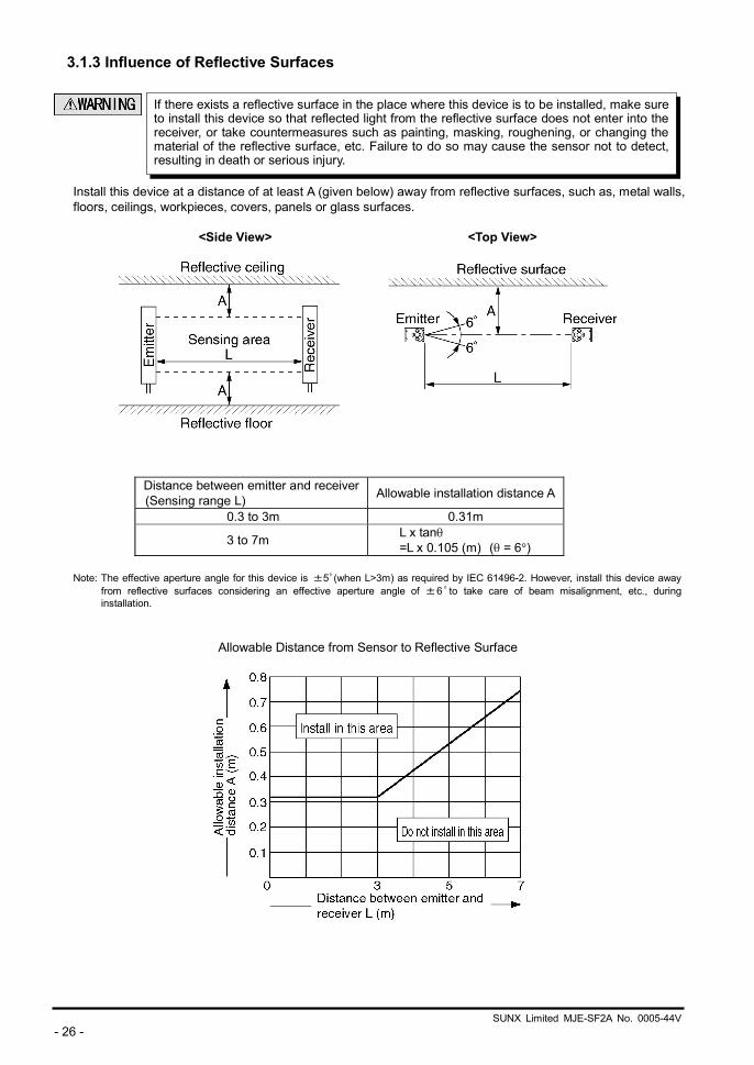
3.1.3 Influence of Reflective Surfaces
Install this device at a distance of at least A (given below) away from reflective surfaces, such as, metal walls, floors, ceilings, workpieces, covers, panels or glass surfaces.
<Side View> <Top View>
Distance between emitter and receiver (Sensing range L) Allowable installation distance A
0.3 to 3m 0.31m
3 to 7m L x tan =L x 0.105 (m) ( = 6 )
Note: The effective aperture angle for this device is ±5゜(when L>3m) as required by IEC 61496-2. However, install this device away
from reflective surfaces considering an effective aperture angle of ±6゜ to take care of beam misalignment, etc., during installation.
Allowable Distance from Sensor to Reflective Surface
If there exists a reflective surface in the place where this device is to be installed, make sure to install this device so that reflected light from the reflective surface does not enter into the receiver, or take countermeasures such as painting, masking, roughening, or changing the material of the reflective surface, etc. Failure to do so may cause the sensor not to detect, resulting in death or serious injury.
SUNX Limited MJE-SF2A No. 0005-44V - 27 -
3.2 Connection Configuration
<Reference> Refer to ‘3.4.2 Sensor Wiring Diagrams’ for details of the connection (wiring) method.
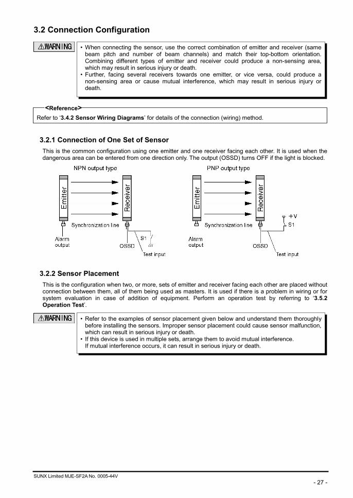
3.2.1 Connection of One Set of Sensor This is the common configuration using one emitter and one receiver facing each other. It is used when the dangerous area can be entered from one direction only. The output (OSSD) turns OFF if the light is blocked.
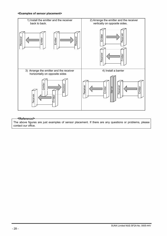
3.2.2 Sensor Placement This is the configuration when two, or more, sets of emitter and receiver facing each other are placed without connection between them, all of them being used as masters. It is used if there is a problem in wiring or for system evaluation in case of addition of equipment. Perform an operation test by referring to ‘3.5.2 Operation Test’.
• When connecting the sensor, use the correct combination of emitter and receiver (same beam pitch and number of beam channels) and match their top-bottom orientation. Combining different types of emitter and receiver could produce a non-sensing area, which may result in serious injury or death.
• Further, facing several receivers towards one emitter, or vice versa, could produce a non-sensing area or cause mutual interference, which may result in serious injury or death.
• Refer to the examples of sensor placement given below and understand them thoroughly before installing the sensors. Improper sensor placement could cause sensor malfunction, which can result in serious injury or death.
• If this device is used in multiple sets, arrange them to avoid mutual interference. If mutual interference occurs, it can result in serious injury or death.
SUNX Limited MJE-SF2A No. 0005-44V - 28 -
<Examples of sensor placement>
1) Install the emitter and the receiver back to back.
2) Arrange the emitter and the receiver vertically on opposite sides.
3) Arrange the emitter and the receiver horizontally on opposite sides
4) Install a barrier
<Reference> The above figures are just examples of sensor placement. If there are any questions or problems, please contact our office.
SUNX Limited MJE-SF2A No. 0005-44V - 29 -
3.3 Mounting
3.3.1 Mounting Procedure
<Reference> • Mount the emitter and the receiver at the same level and parallel to each other. The effective aperture angle
of this device is ±5゜or less for a detection distance exceeding 3m. • Unless otherwise specified, the following mounting procedure is common for both emitter and receiver. For
the mounting, prepare the mounting holes on the mounting surface by referring to ‘2.4 Dimensions’. • For laser alignment, it is useful to use the beam alignment tool for light curtain (SF-LAT-2N) (optional).
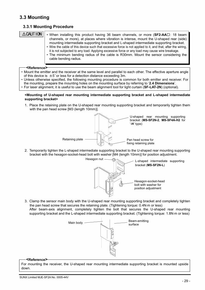
<Mounting of U-shaped rear mounting intermediate supporting bracket and L-shaped intermediate supporting bracket>
1. Place the retaining plate on the U-shaped rear mounting supporting bracket and temporarily tighten them with the pan head screw [M3 (length 10mm)].
2. Temporarily tighten the L-shaped intermediate supporting bracket to the U-shaped rear mounting supporting
bracket with the hexagon-socket-head bolt with washer [M4 (length 10mm)] for position adjustment.
3. Clamp the sensor main body with the U-shaped rear mounting supporting bracket and completely tighten
the pan head screw that secures the retaining plate. (Tightening torque: 0.4N m or less) After beam-axis alignment, completely tighten the bolt that secures the U-shaped rear mounting supporting bracket and the L-shaped intermediate supporting bracket. (Tightening torque: 1.8N m or less)
<Reference>
For mounting the receiver, the U-shaped rear mounting intermediate supporting bracket is mounted upside down.
• When installing this product having 36 beam channels, or more (SF2-AA□: 18 beam channels, or more), at places where vibration is intense, mount the U-shaped rear (side) mounting intermediate supporting bracket and L-shaped intermediate supporting bracket.
• Wire the cable of this device such that excessive force is not applied to it, and that, after the wiring, it is not subjected to any load. Applying excessive force or any load may cause wire breakage.
• The minimum bending radius of the cable is R30mm. Mount the sensor considering the cable bending radius.
Retaining plate Pan head screw for fixing retaining plate
L-shaped intermediate supporting bracket (MS-SF2N-L)
Hexagon-socket-head bolt with washer for position adjustment
Main body Beam-emitting surface
U-shaped rear mounting supporting bracket (MS-SF2N-2, MS-SF4A-H2 for ‘-H’ type)
Hexagon nut
SUNX Limited MJE-SF2A No. 0005-44V - 30 -
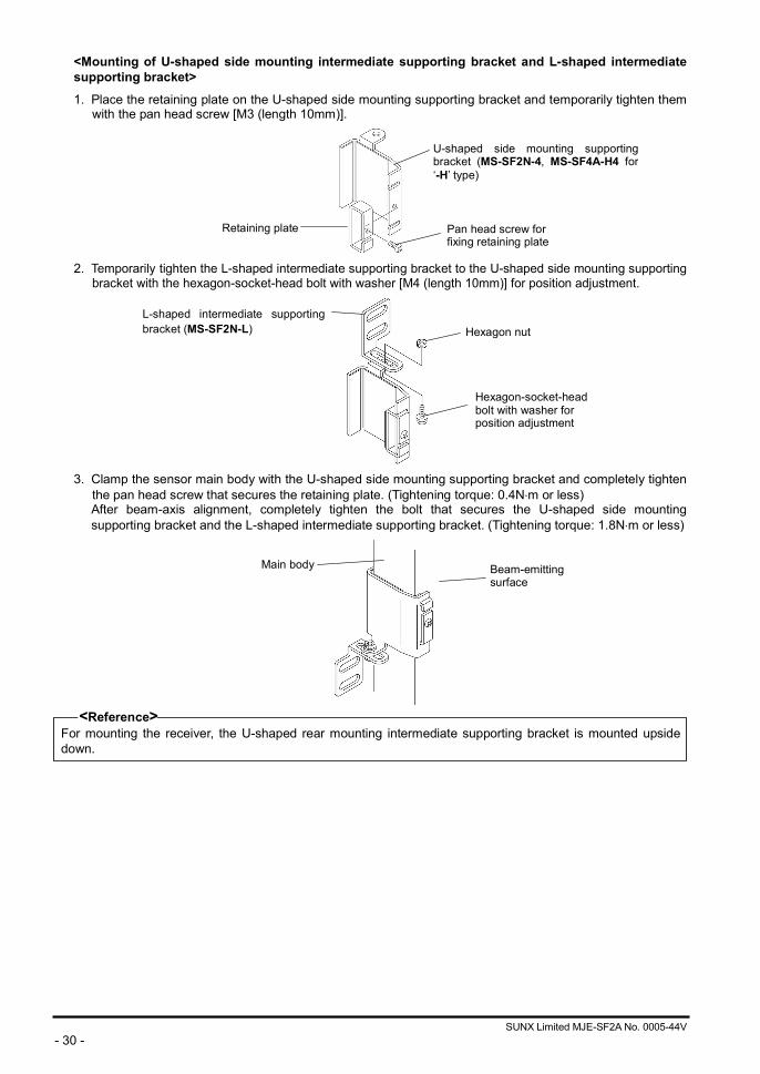
<Mounting of U-shaped side mounting intermediate supporting bracket and L-shaped intermediate supporting bracket>
1. Place the retaining plate on the U-shaped side mounting supporting bracket and temporarily tighten them with the pan head screw [M3 (length 10mm)].
2. Temporarily tighten the L-shaped intermediate supporting bracket to the U-shaped side mounting supporting
bracket with the hexagon-socket-head bolt with washer [M4 (length 10mm)] for position adjustment.
3. Clamp the sensor main body with the U-shaped side mounting supporting bracket and completely tighten
the pan head screw that secures the retaining plate. (Tightening torque: 0.4N m or less) After beam-axis alignment, completely tighten the bolt that secures the U-shaped side mounting supporting bracket and the L-shaped intermediate supporting bracket. (Tightening torque: 1.8N m or less)
<Reference>
For mounting the receiver, the U-shaped rear mounting intermediate supporting bracket is mounted upside down.
Hexagon nut
Retaining plate Pan head screw for fixing retaining plate
Main body Beam-emitting surface
U-shaped side mounting supportingbracket (MS-SF2N-4, MS-SF4A-H4 for‘-H’ type)
L-shaped intermediate supportingbracket (MS-SF2N-L)
Hexagon-socket-head bolt with washer for position adjustment
SUNX Limited MJE-SF2A No. 0005-44V - 31 -
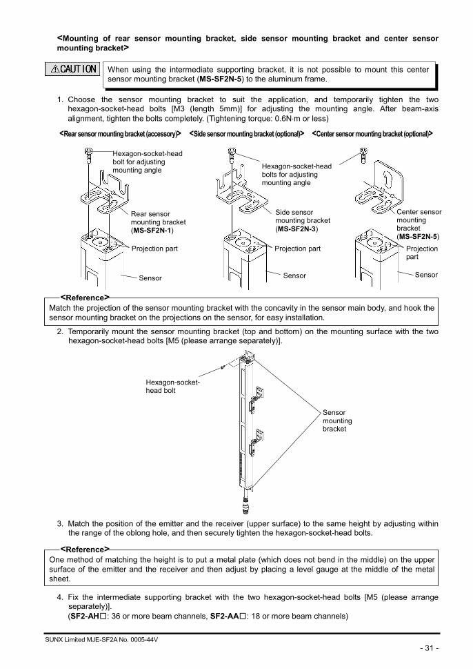
<Mounting of rear sensor mounting bracket, side sensor mounting bracket and center sensor mounting bracket>
1. Choose the sensor mounting bracket to suit the application, and temporarily tighten the two hexagon-socket-head bolts [M3 (length 5mm)] for adjusting the mounting angle. After beam-axis alignment, tighten the bolts completely. (Tightening torque: 0.6N m or less)
<Rear sensor mounting bracket (accessory)> <Side sensor mounting bracket (optional)> <Center sensor mounting bracket (optional)>
<Reference>
Match the projection of the sensor mounting bracket with the concavity in the sensor main body, and hook the sensor mounting bracket on the projections on the sensor, for easy installation.
2. Temporarily mount the sensor mounting bracket (top and bottom) on the mounting surface with the two hexagon-socket-head bolts [M5 (please arrange separately)].
3. Match the position of the emitter and the receiver (upper surface) to the same height by adjusting within
the range of the oblong hole, and then securely tighten the hexagon-socket-head bolts.
<Reference> One method of matching the height is to put a metal plate (which does not bend in the middle) on the upper surface of the emitter and the receiver and then adjust by placing a level gauge at the middle of the metal sheet. 4. Fix the intermediate supporting bracket with the two hexagon-socket-head bolts [M5 (please arrange
separately)]. (SF2-AH□: 36 or more beam channels, SF2-AA□: 18 or more beam channels)
Hexagon-socket-headbolt for adjusting mounting angle
Sensor
Rear sensor mounting bracket(MS-SF2N-1)
Side sensor mounting bracket(MS-SF2N-3)
Hexagon-socket- head bolt
Sensor mounting bracket
Sensor Sensor
Center sensor mounting bracket (MS-SF2N-5)
Hexagon-socket-headbolts for adjusting mounting angle
When using the intermediate supporting bracket, it is not possible to mount this center sensor mounting bracket (MS-SF2N-5) to the aluminum frame.
Projection part Projection part Projection part
SUNX Limited MJE-SF2A No. 0005-44V - 32 -
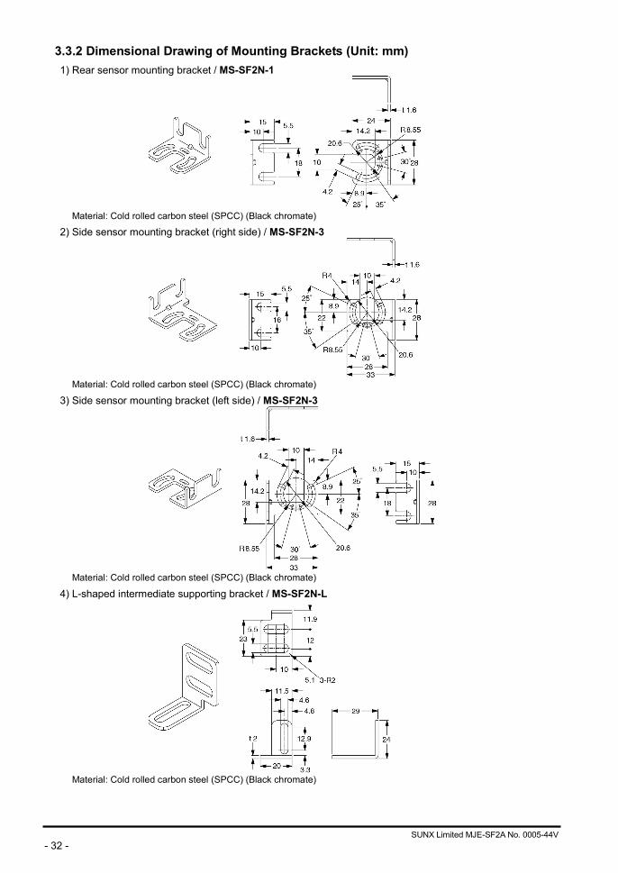
3.3.2 Dimensional Drawing of Mounting Brackets (Unit: mm) 1) Rear sensor mounting bracket / MS-SF2N-1
Material: Cold rolled carbon steel (SPCC) (Black chromate)
2) Side sensor mounting bracket (right side) / MS-SF2N-3
Material: Cold rolled carbon steel (SPCC) (Black chromate)
3) Side sensor mounting bracket (left side) / MS-SF2N-3
Material: Cold rolled carbon steel (SPCC) (Black chromate)
4) L-shaped intermediate supporting bracket / MS-SF2N-L
Material: Cold rolled carbon steel (SPCC) (Black chromate)
SUNX Limited MJE-SF2A No. 0005-44V - 33 -
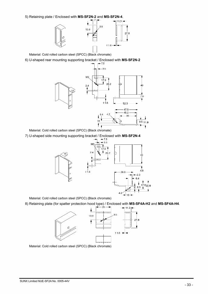
5) Retaining plate / Enclosed with MS-SF2N-2 and MS-SF2N-4.
Material: Cold rolled carbon steel (SPCC) (Black chromate)
6) U-shaped rear mounting supporting bracket / Enclosed with MS-SF2N-2
Material: Cold rolled carbon steel (SPCC) (Black chromate)
7) U-shaped side mounting supporting bracket / Enclosed with MS-SF2N-4
Material: Cold rolled carbon steel (SPCC) (Black chromate)
8) Retaining plate (for spatter protection hood type) / Enclosed with MS-SF4A-H2 and MS-SF4A-H4.
Material: Cold rolled carbon steel (SPCC) (Black chromate)
SUNX Limited MJE-SF2A No. 0005-44V - 34 -
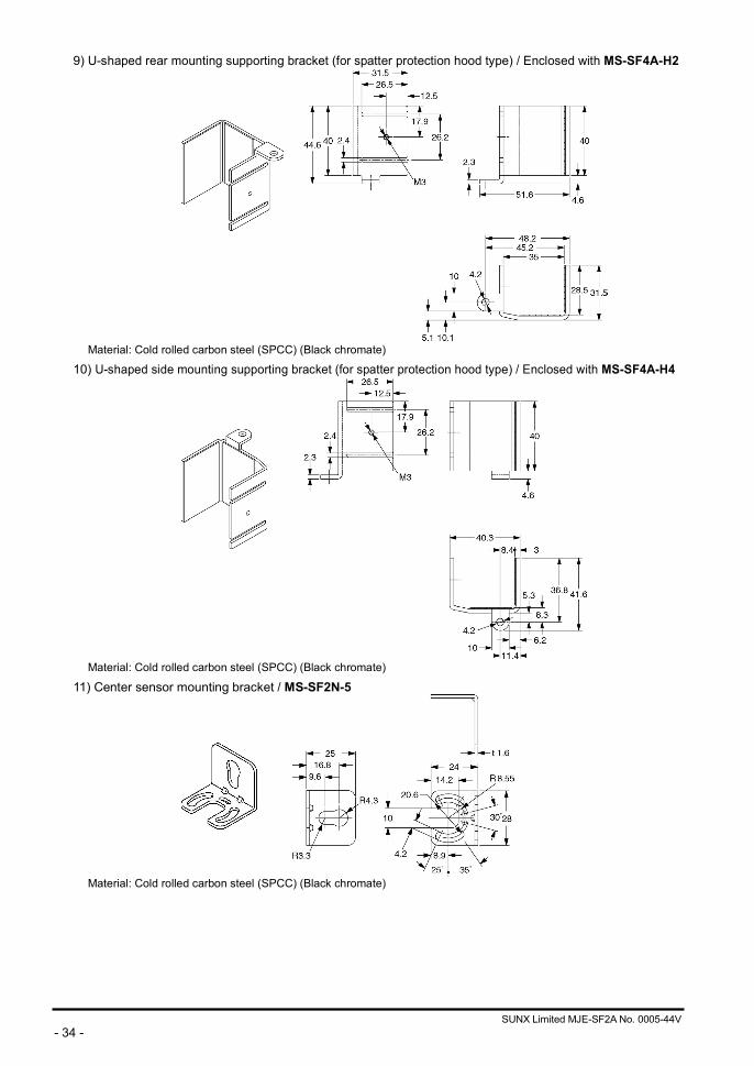
9) U-shaped rear mounting supporting bracket (for spatter protection hood type) / Enclosed with MS-SF4A-H2
Material: Cold rolled carbon steel (SPCC) (Black chromate)
10) U-shaped side mounting supporting bracket (for spatter protection hood type) / Enclosed with MS-SF4A-H4
Material: Cold rolled carbon steel (SPCC) (Black chromate)
11) Center sensor mounting bracket / MS-SF2N-5
Material: Cold rolled carbon steel (SPCC) (Black chromate)
SUNX Limited MJE-SF2A No. 0005-44V - 35 -
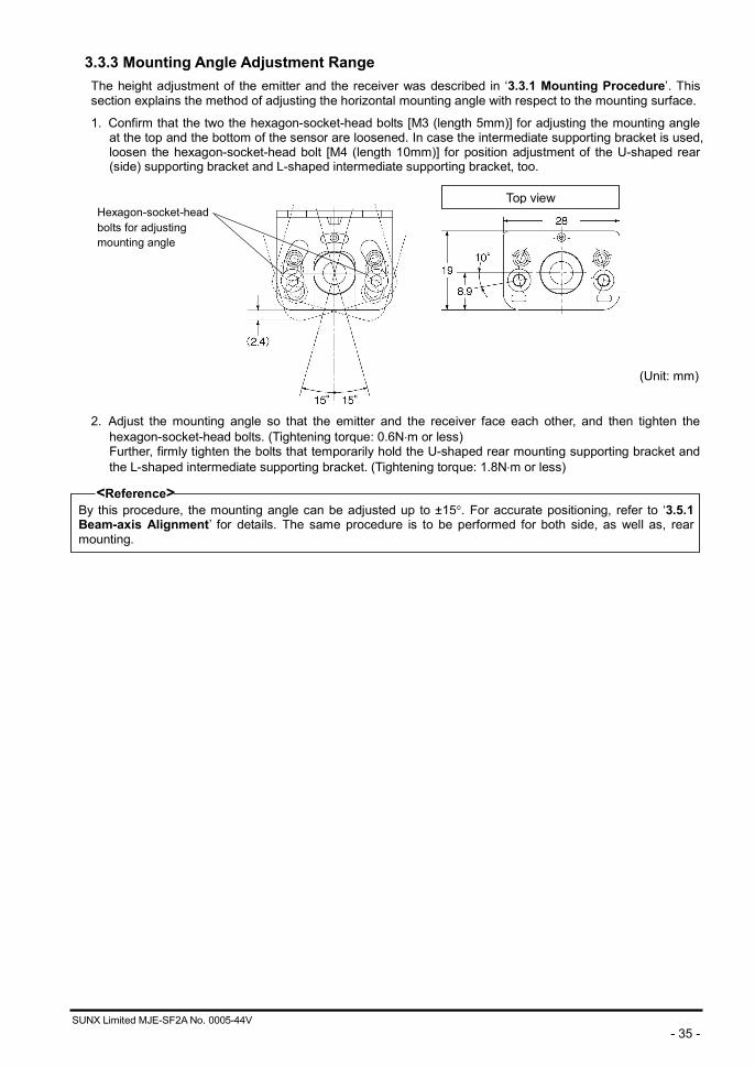
3.3.3 Mounting Angle Adjustment Range The height adjustment of the emitter and the receiver was described in ‘3.3.1 Mounting Procedure’. This section explains the method of adjusting the horizontal mounting angle with respect to the mounting surface.
1. Confirm that the two the hexagon-socket-head bolts [M3 (length 5mm)] for adjusting the mounting angle at the top and the bottom of the sensor are loosened. In case the intermediate supporting bracket is used, loosen the hexagon-socket-head bolt [M4 (length 10mm)] for position adjustment of the U-shaped rear (side) supporting bracket and L-shaped intermediate supporting bracket, too.
2. Adjust the mounting angle so that the emitter and the receiver face each other, and then tighten the
hexagon-socket-head bolts. (Tightening torque: 0.6N m or less) Further, firmly tighten the bolts that temporarily hold the U-shaped rear mounting supporting bracket and the L-shaped intermediate supporting bracket. (Tightening torque: 1.8N m or less)
<Reference> By this procedure, the mounting angle can be adjusted up to ±15 . For accurate positioning, refer to ‘3.5.1 Beam-axis Alignment’ for details. The same procedure is to be performed for both side, as well as, rear mounting.
Hexagon-socket-head bolts for adjusting mounting angle
(Unit: mm)
Top view
SUNX Limited MJE-SF2A No. 0005-44V - 36 -
3.4 Wiring
3.4.1 Power Supply Unit
<Reference> A specialist who has the required electrical knowledge should perform the wiring. The DC power supply unit must satisfy the conditions given below: 1) Power supply unit authorized in the region where this device is to be used. 2) Power supply unit conforming to EMC Directive and Low-voltage Directive (In case CE marking conformity is
required.) 3) Power supply unit conforming to the Low-voltage directive and with an output of 100VA or less. 4) The frame ground (F.G.) terminal must be connected to ground when using a commercially available
switching regulator. 5) Power supply unit with an output holding time of 20ms or more. 6) Use an isolation transformer for the DC power supply unit. 7) In case a surge is generated, take countermeasures such as connecting a surge absorber to the origin of
the surge. 8) Power supply unit corresponding to CLASS 2 (In case UL / cUL conformity is required.)
《Additional information》 As provided in IEC 60536 (CLASS: Protection against Electric Shock), this power supply should require no ground earth and satisfy the insulation distance called double insulation or reinforced insulation. In case the power supply conforms to Low-voltage directive and has an output of 100VA or less, it can be used as a suitable product.
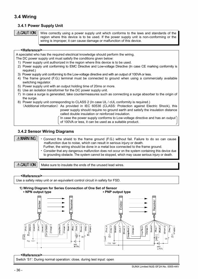
3.4.2 Sensor Wiring Diagrams
<Reference> Use a safety relay unit or an equivalent control circuit in safety for FSD.
1) Wiring Diagram for Series Connection of One Set of Sensor
NPN output type PNP output type
<Reference> Switch ‘S1’: During normal operation: close, during test input: open
Wire correctly using a power supply unit which conforms to the laws and standards of theregion where this device is to be used. If the power supply unit is non-conforming or the wiring is improper, it can cause damage or malfunction of this device.
Make sure to insulate the ends of the unused lead wires.
• Connect the shield to the frame ground (F.G.) without fail. Failure to do so can cause malfunction due to noise, which can result in serious injury or death. Further, the wiring should be done in a metal box connected to the frame ground.
• Consider that any dangerous malfunction does not occur on the system containing this device due to grounding obstacle. The system cannot be stopped, which may cause serious injury or death.
SUNX Limited MJE-SF2A No. 0005-44V - 37 -
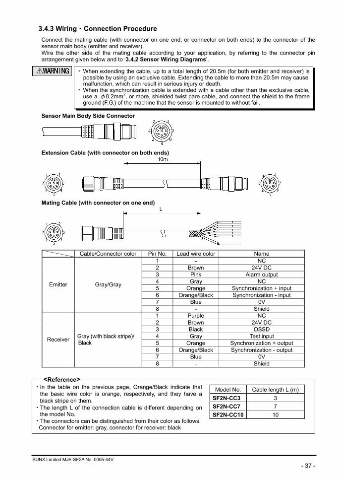
3.4.3 Wiring・Connection Procedure Connect the mating cable (with connector on one end, or connector on both ends) to the connector of the sensor main body (emitter and receiver). Wire the other side of the mating cable according to your application, by referring to the connector pin arrangement given below and to ‘3.4.2 Sensor Wiring Diagrams’.
Sensor Main Body Side Connector
Extension Cable (with connector on both ends)
Mating Cable (with connector on one end)
Cable/Connector color Pin No. Lead wire color Name
1 - NC 2 Brown 24V DC 3 Pink Alarm output 4 Gray NC 5 Orange Synchronization + input 6 Orange/Black Synchronization - input 7 Blue 0V
Emitter Gray/Gray
8 - Shield 1 Purple NC 2 Brown 24V DC 3 Black OSSD 4 Gray Test input 5 Orange Synchronization + output 6 Orange/Black Synchronization - output 7 Blue 0V
Receiver Gray (with black stripe)/ Black
8 - Shield
<Reference> • In the table on the previous page, Orange/Black indicate that
the basic wire color is orange, respectively, and they have a black stripe on them.
• The length L of the connection cable is different depending on the model No.
• The connectors can be distinguished from their color as follows. Connector for emitter: gray, connector for receiver: black
Model No. Cable length L (m) SF2N-CC3 3 SF2N-CC7 7 SF2N-CC10 10
• When extending the cable, up to a total length of 20.5m (for both emitter and receiver) ispossible by using an exclusive cable. Extending the cable to more than 20.5m may cause malfunction, which can result in serious injury or death.
• When the synchronization cable is extended with a cable other than the exclusive cable, use a φ0.2mm2, or more, shielded twist pare cable, and connect the shield to the frame ground (F.G.) of the machine that the sensor is mounted to without fail.
SUNX Limited MJE-SF2A No. 0005-44V - 38 -
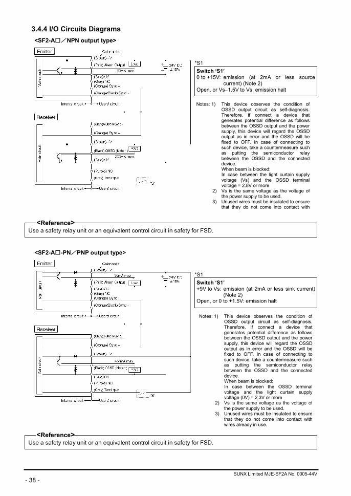
3.4.4 I/O Circuits Diagrams <SF2-A□/NPN output type>
<Reference> Use a safety relay unit or an equivalent control circuit in safety for FSD.
<SF2-A□-PN/PNP output type>
<Reference> Use a safety relay unit or an equivalent control circuit in safety for FSD.
*S1Switch ‘S1’0 to +15V: emission (at 2mA or less source
current) (Note 2) Open, or Vs 1.5V to Vs: emission halt
*S1Switch ‘S1’+9V to Vs: emission (at 2mA or less sink current)
(Note 2) Open, or 0 to +1.5V: emission halt
Notes: 1) This device observes the condition of OSSD output circuit as self-diagnosis. Therefore, if connect a device that generates potential difference as follows between the OSSD output and the power supply, this device will regard the OSSD output as in error and the OSSD will be fixed to OFF. In case of connecting to such device, take a countermeasure such as putting the semiconductor relay between the OSSD and the connected device.
When beam is blocked: In case between the light curtain supply voltage (Vs) and the OSSD terminal voltage = 2.8V or more
2) Vs is the same voltage as the voltage of the power supply to be used.
3) Unused wires must be insulated to ensure that they do not come into contact with
Notes: 1) This device observes the condition of OSSD output circuit as self-diagnosis. Therefore, if connect a device that generates potential difference as follows between the OSSD output and the power supply, this device will regard the OSSD output as in error and the OSSD will be fixed to OFF. In case of connecting to such device, take a countermeasure such as putting the semiconductor relay between the OSSD and the connected device.
When beam is blocked: In case between the OSSD terminal voltage and the light curtain supply voltage (0V) = 2.3V or more
2) Vs is the same voltage as the voltage of the power supply to be used.
3) Unused wires must be insulated to ensure that they do not come into contact with wires already in use.
SUNX Limited MJE-SF2A No. 0005-44V - 39 -
3.5 Adjustment
3.5.1 Beam-axis Alignment 1. Turn ON the power supply unit of this device.
2. Check that the fault indicators (yellow) of the emitter and the receiver are off. • If the fault indicator (yellow) lights up or blinks, refer to ‘Chapter 5 Troubleshooting’, and report the
contents to the maintenance in-charge.
<Reference> Refer to ‘3.3.1 Mounting Procedure’ for the operations beyond this. For laser alignment, it is useful to use the beam alignment tool for light curtain (SF-LAT-2N) (optional).
3. Loosen the two hexagon-socket-head bolts [M3 (length 5mm)] for adjusting the mounting angle at the top
and the bottom of the emitter.
<Reference> If the intermediate supporting bracket has been mounted on the sensor main body, loosen the hexagon-socket-head bolt with washer for position adjustment [M4 (length 10mm)] before alignment.
Top view Hexagon-socket-head bolts for adjusting mounting angle
(Unit: mm)
SUNX Limited MJE-SF2A No. 0005-44V - 40 -
4. Adjust the emitter/receiver so that the beam-axis alignment indicators in the display of the emitter and receiver light up.
<Reference>
The beam-axis alignment indicator indicates the reception status for each section of a sensor which is divided into 4 sections. For example, when using a 16-beam channel sensor, there are 4 beam channels per section (i.e., 16/4 = 4). When the top end (bottom end) beam channel is received, the top (bottom) of the beam-axis alignment indicator blinks in red.
(Example) 16 beam channels
All the 4 beam channels divided into each section are received, the beam-axis alignment indicator lights up in red. The beam-axis alignment indicators corresponding to the different sections light up in red, one by one, when the beam channels of the respective sections are received. When all the beam channels are received, the OSSD turns ON, and all the four indicators of the beam-axis alignment indicator turn into green. For details, refer to ‘3-5-3 Operation’.
5. Tighten the hexagon-socket-head bolts [M3 (length 5mm)] for adjusting the mounting angle at the top and
the bottom of the emitter to fix the emitter. (Tightening torque: 0.6N m or less)
<Reference> If the intermediate supporting bracket has been mounted on the sensor main body, tighten the hexagon-socket-head bolt [M4 (length 10mm)] for position adjustment. (Tightening torque: 1.8N m or less)
6. Check, once again, that the beam-axis alignment indicators in the display of the emitter and receiver do
light up. Furthermore, ensure that the orange LED of the stable incident beam indicator in the receiver is OFF as well.
SUNX Limited MJE-SF2A No. 0005-44V - 41 -
3.5.2 Operation Test 1. Turn ON the power supply unit of this device.
2. Check that the fault indicators (yellow) of the emitter and the receiver are off. • If the fault indicator (yellow) lights up or blinks, refer to ‘Chapter 5 Troubleshooting’, and report the
contents to the maintenance in-charge.
3. Move the test rod up and down at three positions, just in front of the emitter (A), between the emitter and receiver (B), and just in front of the receiver (C).
4. During Step 3 above, check that the sensor output is in the OFF state and, both, the OSSD indicator (red)
of the receiver and the operation indicator (red) of the emitter light up, as long as the test rod is present within the sensing area. • If the behavior of the output (OSSD) and the turning ON/OFF of the emitter/receiver indicators do not
correspond to the movement of the test rod, refer to ‘Chapter 5 Troubleshooting’, and report the contents to the maintenance in-charge.
<Reference> If the indicators show receipt of light, even though the test rod blocks the light, also check if there is any reflective object or extraneous light source near this device.
Test rod

SUNX Limited MJE-SF2A No. 0005-44V - 42 -
3.5.3 Operation 1) Normal Operation
The status of the emitter/receiver indicators during normal operation is as described below.
Indicators Device Status Emitter Receiver
OSSD
All beams received stably(140% or more)(Note 1)
Lights up in green
Lights up in green
All beams received stably(115 to 140 %) (Note 1)
Lights up in green
Lights up in green
Rec
eptio
n st
atus
Beams received unstably (100 to 115 %) (Note 1)
Lights up in green
Lights up in green (Stable incident beam indicator: lights up in orange)
ON
Notes 1): The threshold value where the output turns to ON from OFF is regarded as the incident beam intensity 100%.
2): Since the color of the operation indicator changes according to the ON/OFF state of OSSD, the operation indicator is marked as OSSD on the sensor.
SUNX Limited MJE-SF2A No. 0005-44V - 43 -
Indicators Device Status Emitter Receiver
OSSD
One or more beams blocked
Lights up in red (OFF for beam blocked channels)
Lights up in red (OFF for beam blocked channels)
Beams other than the top end blocked
The top most beam-axis align- ment indicator: blinks in redOperation indicator: lights up in red
The top most beam-axis align- ment indicator: blinks in redOperation indicator: lights up in red
Beam
blo
cked
sta
tus
Beams other than the bottom end blocked
The bottom most beam-axis alignment indicator: blinks in redOperation indicator: lights up in red
The bottom most beam-axis alignment indicator: blinks in red Operation indicator: lights up in red
OFF
Time Chart
Note: Since the color of the operation indicator changes according to the ON/OFF state of OSSD, the operation indicator is marked as OSSD on the sensor.
SUNX Limited MJE-SF2A No. 0005-44V - 44 -
2) In Case of Emission Halt In case of carrying out self-diagnosis function by using the test input or in case of incorrect wiring, the emission will come to a halt.
The emitter's emission halt indicator (orange) lights up. After removal of the source of error, the machine will return to normal operation automatically without restarting it. However, the machine may operate immediately after its automatic recovery. Hence, we recommend turning the power off and then removing the source of error.
Example: Synchronization signal disconnection, incorrect wiring, short-circuit, etc.
Refer to ‘Chapter 5 Troubleshooting’ and remove the source of error.
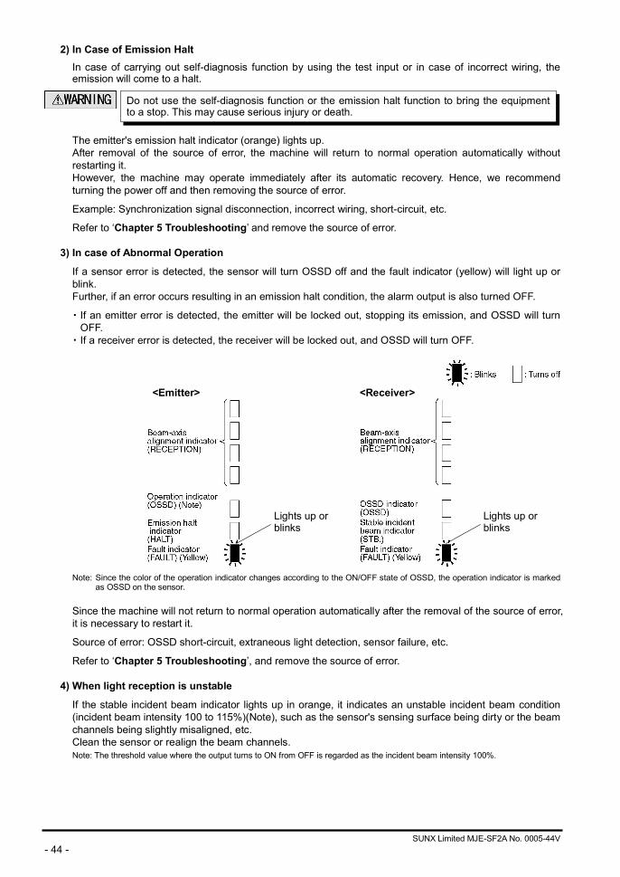
3) In case of Abnormal Operation
If a sensor error is detected, the sensor will turn OSSD off and the fault indicator (yellow) will light up or blink. Further, if an error occurs resulting in an emission halt condition, the alarm output is also turned OFF.
・ If an emitter error is detected, the emitter will be locked out, stopping its emission, and OSSD will turn OFF.
・ If a receiver error is detected, the receiver will be locked out, and OSSD will turn OFF.
<Emitter> <Receiver>
Note: Since the color of the operation indicator changes according to the ON/OFF state of OSSD, the operation indicator is marked as OSSD on the sensor.
Since the machine will not return to normal operation automatically after the removal of the source of error, it is necessary to restart it.
Source of error: OSSD short-circuit, extraneous light detection, sensor failure, etc.
Refer to ‘Chapter 5 Troubleshooting’, and remove the source of error.
4) When light reception is unstable
If the stable incident beam indicator lights up in orange, it indicates an unstable incident beam condition (incident beam intensity 100 to 115%)(Note), such as the sensor's sensing surface being dirty or the beam channels being slightly misaligned, etc. Clean the sensor or realign the beam channels. Note: The threshold value where the output turns to ON from OFF is regarded as the incident beam intensity 100%.
Do not use the self-diagnosis function or the emission halt function to bring the equipment to a stop. This may cause serious injury or death.
Lights up or blinks
Lights up or blinks
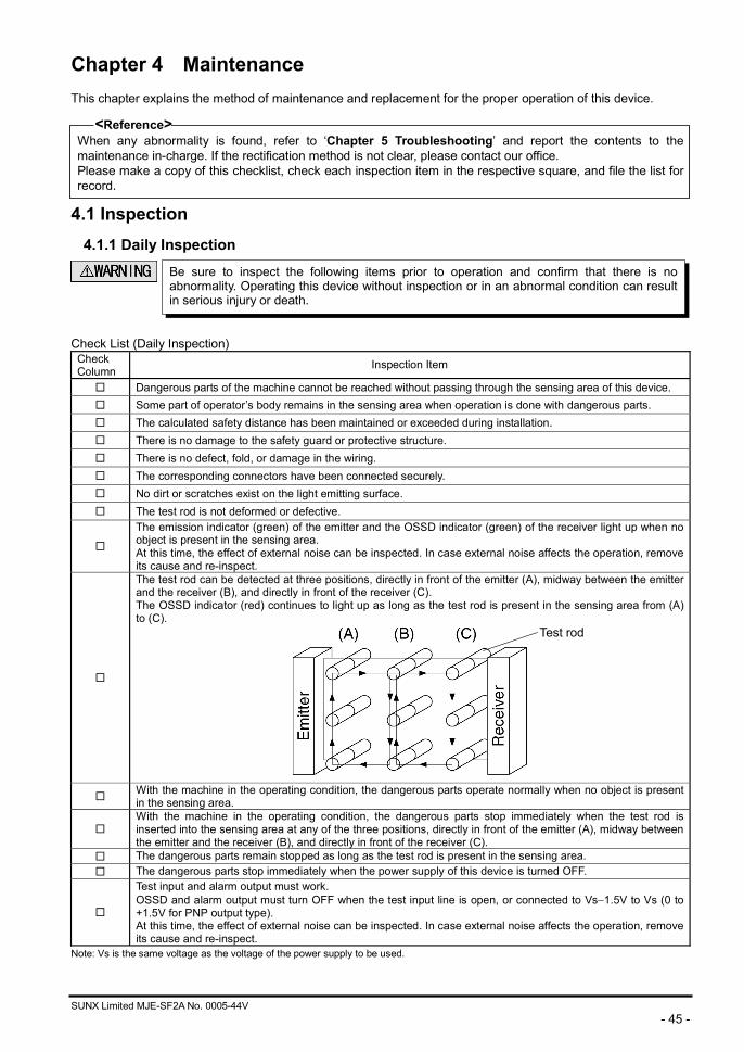
SUNX Limited MJE-SF2A No. 0005-44V - 45 -
Chapter 4 Maintenance This chapter explains the method of maintenance and replacement for the proper operation of this device.
<Reference> When any abnormality is found, refer to ‘Chapter 5 Troubleshooting’ and report the contents to the maintenance in-charge. If the rectification method is not clear, please contact our office. Please make a copy of this checklist, check each inspection item in the respective square, and file the list for record.
4.1 Inspection
4.1.1 Daily Inspection
Check List (Daily Inspection)
Check Column Inspection Item
□ Dangerous parts of the machine cannot be reached without passing through the sensing area of this device. □ Some part of operator’s body remains in the sensing area when operation is done with dangerous parts. □ The calculated safety distance has been maintained or exceeded during installation. □ There is no damage to the safety guard or protective structure. □ There is no defect, fold, or damage in the wiring. □ The corresponding connectors have been connected securely. □ No dirt or scratches exist on the light emitting surface. □ The test rod is not deformed or defective.
□
The emission indicator (green) of the emitter and the OSSD indicator (green) of the receiver light up when no object is present in the sensing area. At this time, the effect of external noise can be inspected. In case external noise affects the operation, remove its cause and re-inspect.
□
The test rod can be detected at three positions, directly in front of the emitter (A), midway between the emitter and the receiver (B), and directly in front of the receiver (C). The OSSD indicator (red) continues to light up as long as the test rod is present in the sensing area from (A) to (C).
□ With the machine in the operating condition, the dangerous parts operate normally when no object is present in the sensing area.
□ With the machine in the operating condition, the dangerous parts stop immediately when the test rod is inserted into the sensing area at any of the three positions, directly in front of the emitter (A), midway between the emitter and the receiver (B), and directly in front of the receiver (C).
□ The dangerous parts remain stopped as long as the test rod is present in the sensing area. □ The dangerous parts stop immediately when the power supply of this device is turned OFF.
□
Test input and alarm output must work. OSSD and alarm output must turn OFF when the test input line is open, or connected to Vs 1.5V to Vs (0 to +1.5V for PNP output type). At this time, the effect of external noise can be inspected. In case external noise affects the operation, remove its cause and re-inspect.
Note: Vs is the same voltage as the voltage of the power supply to be used.
Test rod
Be sure to inspect the following items prior to operation and confirm that there is no abnormality. Operating this device without inspection or in an abnormal condition can result in serious injury or death.
SUNX Limited MJE-SF2A No. 0005-44V - 46 -
4.1.2 Periodic Inspection (Every Six Months)
Check List (Periodic Inspection)
Check Column Inspection Item
□ The structure of the machine does not obstruct any safety mechanisms for stopping operation. □ No modification has been made in the machine controls which obstructs the safety mechanisms. □ The output of this device is correctly detected. □ The wiring from this device is correct. □ The overall response time of the complete machine is equal or less than the calculated value.
□ The actual number of operation cycles (time) of the limited lifetime parts (relay, etc.) is less than their rated operation cycles (time).
□ No screws or connectors of this device are loose. □ No extraneous light source or reflective object has been added near this device.
4.1.3 Inspection after Maintenance Under the following situations, perform all the inspection items mentioned in ‘4.1.1 Daily Inspection’ and ‘4.1.2 Periodic Inspection (Every Six Months)’. 1) When any parts of this device are replaced. 2) When some abnormality is felt during operation. 3) When beam-axis alignment of the emitter and receiver is done. 4) When the device installation place or environment is changed. 5) When the wiring method or wiring layout is changed. 6) When FSD parts are replaced. 7) When FSD setting is changed.
Be sure to inspect the following items every six months and confirm that there is no abnormality. Operating this device without inspection or in an abnormal condition can result in serious injury or death.
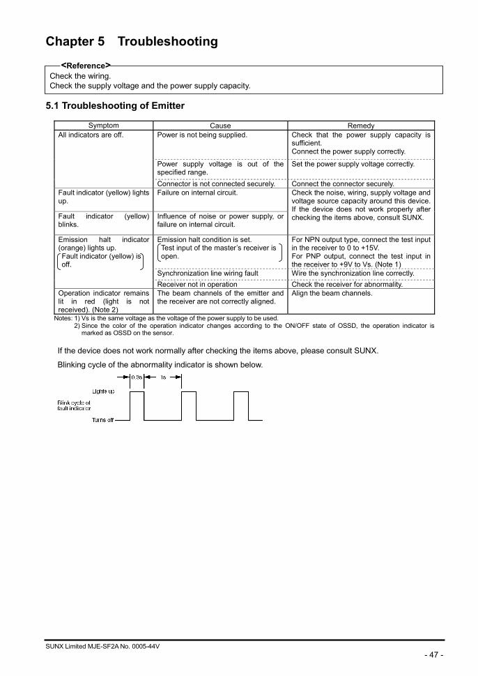
SUNX Limited MJE-SF2A No. 0005-44V - 47 -
Chapter 5 Troubleshooting
<Reference> Check the wiring. Check the supply voltage and the power supply capacity.
5.1 Troubleshooting of Emitter
Symptom Cause Remedy Power is not being supplied.
Check that the power supply capacity is sufficient. Connect the power supply correctly.
Power supply voltage is out of the specified range.
Set the power supply voltage correctly.
All indicators are off.
Connector is not connected securely. Connect the connector securely. Fault indicator (yellow) lights up.
Failure on internal circuit.
Fault indicator (yellow) blinks.
Influence of noise or power supply, or failure on internal circuit.
Check the noise, wiring, supply voltage and voltage source capacity around this device. If the device does not work properly after checking the items above, consult SUNX.
Emission halt condition is set. Test input of the master’s receiver is open.
For NPN output type, connect the test input in the receiver to 0 to +15V. For PNP output, connect the test input in the receiver to +9V to Vs. (Note 1)
Synchronization line wiring fault Wire the synchronization line correctly.
Emission halt indicator (orange) lights up. Fault indicator (yellow) is off.
Receiver not in operation Check the receiver for abnormality. Operation indicator remains lit in red (light is not received). (Note 2)
The beam channels of the emitter and the receiver are not correctly aligned.
Align the beam channels.
Notes: 1) Vs is the same voltage as the voltage of the power supply to be used. 2) Since the color of the operation indicator changes according to the ON/OFF state of OSSD, the operation indicator is
marked as OSSD on the sensor.
If the device does not work normally after checking the items above, please consult SUNX.
Blinking cycle of the abnormality indicator is shown below.
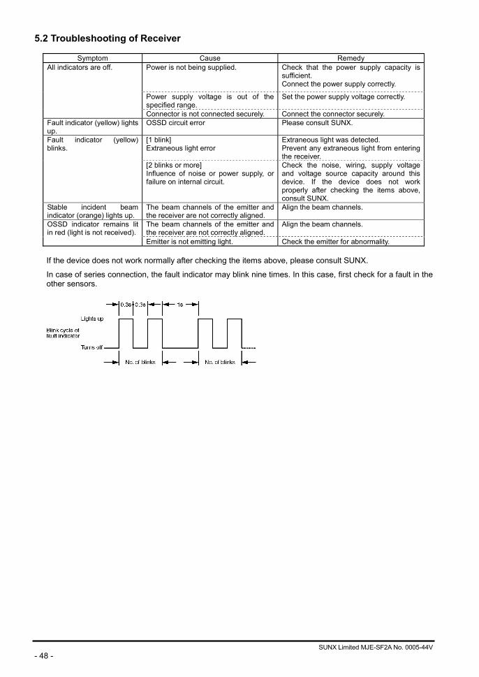
SUNX Limited MJE-SF2A No. 0005-44V - 48 -
5.2 Troubleshooting of Receiver
Symptom Cause Remedy Power is not being supplied.
Check that the power supply capacity is sufficient. Connect the power supply correctly.
Power supply voltage is out of the specified range.
Set the power supply voltage correctly.
All indicators are off.
Connector is not connected securely. Connect the connector securely. Fault indicator (yellow) lights up.
OSSD circuit error Please consult SUNX.
[1 blink] Extraneous light error
Extraneous light was detected. Prevent any extraneous light from entering the receiver.
Fault indicator (yellow) blinks.
[2 blinks or more] Influence of noise or power supply, or failure on internal circuit.
Check the noise, wiring, supply voltage and voltage source capacity around this device. If the device does not work properly after checking the items above, consult SUNX.
Stable incident beam indicator (orange) lights up.
The beam channels of the emitter and the receiver are not correctly aligned.
Align the beam channels.
The beam channels of the emitter and the receiver are not correctly aligned.
Align the beam channels. OSSD indicator remains lit in red (light is not received).
Emitter is not emitting light. Check the emitter for abnormality.
If the device does not work normally after checking the items above, please consult SUNX.
In case of series connection, the fault indicator may blink nine times. In this case, first check for a fault in the other sensors.
SUNX Limited MJE-SF2A No. 0005-44V - 49 -
Chapter 6 Others This section gives additional information for the effective use of this instruction manual.
6.1 Glossary EN 61496-1 The European standard that pertains to machine safety, especially electro-sensitive IEC 61496-1/2 protective equipment (ESPE). EN 61496-1, IEC 61496-1 or UL 61496-1 gives general rules for UL 61496-1/2 failure mode and effect analysis, EMC requirements, etc. IEC 61496-2 or UL 61496-2 specifies
effective aperture angle, protection against extraneous light sources, etc., for active opto-electronic protective devices (AOPD).
UL 1998 UL standard for safety-related software with regard to programmable components. ESPE The abbreviation for Electro-Sensitive Protective Equipment. OSSD The abbreviation for Output Signal Switching Device. A component of the area sensor which
turns off when light of the sensor unit is blocked. FSD The abbreviation for Final Switching Device. The component of the machine’s safety related
control system that open-circuits the MPCE circuit when the OSSD operates due to the light from the sensor unit being blocked.
Test Rod This is a rod for checking the detection capability of this device. It has dimensions
corresponding to the minimum sensing object for this device. Lockout It is one of the safe states of this device. Operation is stopped if the self-diagnosis function
determines that an irrecoverable failure (OSSD does not operate normally, etc.) has occurred. If an emitter is in lockout condition, it will stop emitting light. If a receiver is in lockout condition, OSSD is turned OFF.
Safety distance It is the minimum distance that must be maintained between the light curtain and the
dangerous parts of a machine so that the machine can be stopped before a human body or an object can reach the dangerous parts.
Protective height The length of the beam axis direction that the min. sensing object can be detected. (Sensing height) SF2-AH□: The length from the center of the first beam channel to the center of the last
beam channel in addition to 50mm (25mm upward + 25mm downward). SF2-AA□: The length from the center of the first beam channel to the center of the last
beam channel in addition to 70mm (25mm upward + 45mm downward). Sensing range It is the range between the facing emitter and receiver. Sensing area It is the area over which intrusion by people or objects can be detected by one set of sensor. It is given by the product of the protective height and the operating range. Self-diagnosis It enables even more detailed self-diagnosis, in addition to the self-diagnosis under normal function operating conditions.
Test input This function enables checking of the receiver operation by turning off light emission.
Emission halt NPN output: It is switchable either emission stop, when the test input is open, or connected Function to Vs 1.5V to Vs, or normal emission stop, when the test input is connected to
0 to +15V. PNP output: It is switchable either emission stop, when the test input is open, or connected
to 0 to +1.5V, or normal emission stop, when the test input is connected to +9V to Vs.
PSDI The abbreviation for Presence Sensing Device Initiation.
This is a safety device that the system re-starts automatically after the system was forcibly stopped due to a detection.
SUNX Limited MJE-SF2A No. 0005-44V - 50 -
Revision History First edition: May 24, 2002 Second edition: August 20, 2002 Third edition: October 1, 2002 Fourth edition: March 16, 2004 Fifth edition: August 1, 2007
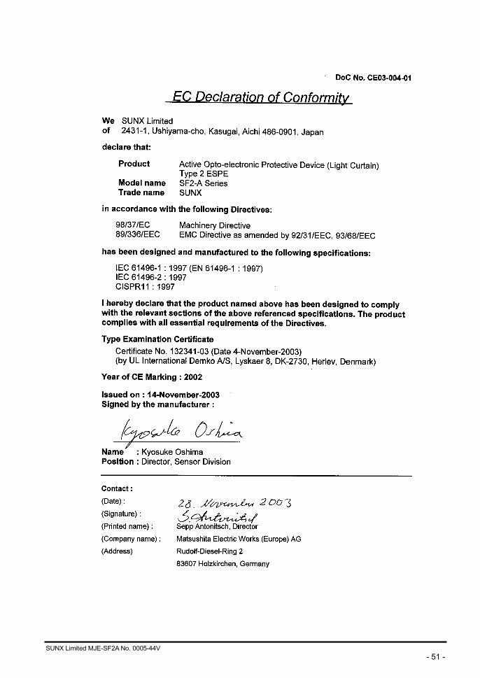
SUNX Limited MJE-SF2A No. 0005-44V - 51 -
Warranty Period
SUNX warrants this product for twelve (12) months from the date of shipment or delivery to the purchaser’s appointed warehouse.
Scope of Warranty
During the above mentioned period, if a failure of the product occurs under normal use and operation, and if SUNX determines that it is responsible for the failure, it shall repair the defect or replace the product. However, in no event shall SUNX be liable for the failure, damage or loss stipulated below:
1) Failure caused by instructions, standards, or handling specified by the customer 2) Failure caused by modifications done in the structure, capabilities, specifications, etc., without
consulting SUNX, after the purchase or the delivery of the product 3) Failure caused by a development which could not be foreseen based upon the technology in
practice at the time of purchase or contract 4) Failure caused by use which deviates from the conditions/environment given in the product
catalog or specifications 5) In case this product is used by being incorporated in the customer’s machine, failure which could
be avoided if the customer’s machine had functions and structure commonly accepted in the industry
6) Failure due to Force Majeure Further, the warranty given here is limited only to this product which has been purchased or delivered. SUNX shall not be responsible for any consequential damage or loss arising out of the failure of this product.
Scope of Service The cost of the product delivered does not include the cost of dispatching an engineer, etc. In case any such service is needed, it should be requested separately.