Embed Size (px)
Citation preview
Sunny Backup 5000Installation & Instruction Manual
Technical Description Version 1.1 SBU5000-TEN081211IMEN-SBU5000

111# Inverter Total Meters112# Inverter Device Meters
210# Inverter Settings
Battery
240# Relay Settings
250# System Settings260# Password Setting
220# Settings
230# Backup Settings
310# Inverter Diagnosis
330# Backup
320# Battery Diagnosis
Diagnosis
510# Operation Inverter520# Battery530# Operation Backup
Operation
540# Operation Generator550# Operation MMC
131# Total Meters132# Grid State133# Generator State134# Device Meters
241# Relay General242# Relay Load243# Relay Timer
311# Total System Diag312# Inverter Device Diag
Home Screen100# METERS
200# SETTINGS
300# DIAGNOSIS
400# HISTORY
500# OPERATION
600# DIRECT ACCESS
331# Grid Diag332# Generator Diag
231# General232# Grid Control233# Generator Control234# Generator Start235# Authentification
221# Battery Property222# Battery Charge Mode223# Battery Protect Mode224# Battery Silent Mode
110# Inverter Meters
120# Battery
130# Backup
Meters
Meters
150# Compact Meters
410# Failures Current420# Failure History430# Event History
Select Name:Select Number:

SMA Technologie AG Table of Contents
Technical Description SBU5000-TEN081211 Page 3
Table of Contents1 Notes on this Manual. . . . . . . . . . . . . . . . . . . . . . 91.1 Validity . . . . . . . . . . . . . . . . . . . . . . . . . . . . . . . . . 91.2 Symbols Used . . . . . . . . . . . . . . . . . . . . . . . . . . . . 91.3 Syntax. . . . . . . . . . . . . . . . . . . . . . . . . . . . . . . . . 10
2 The Sunny Backup 5000 . . . . . . . . . . . . . . . . . . 112.1 Properties . . . . . . . . . . . . . . . . . . . . . . . . . . . . . . 112.2 At a Glance. . . . . . . . . . . . . . . . . . . . . . . . . . . . . 182.3 Dimensions . . . . . . . . . . . . . . . . . . . . . . . . . . . . . 192.4 Scope of Delivery Sunny Backup 5000 . . . . . . . . . 202.5 Required Tools and Resources . . . . . . . . . . . . . . . . 212.6 Accessories (Optional) . . . . . . . . . . . . . . . . . . . . . 222.7 SMA Products (Optional) . . . . . . . . . . . . . . . . . . . 222.8 Name Plate/Firmware Version . . . . . . . . . . . . . . . . 23
3 Safety Instructions . . . . . . . . . . . . . . . . . . . . . . . 253.1 Important Notes Regarding Operation . . . . . . . . . . 253.2 Potential Hazards . . . . . . . . . . . . . . . . . . . . . . . . . 26
4 Installation . . . . . . . . . . . . . . . . . . . . . . . . . . . . . 294.1 Lifting/Moving . . . . . . . . . . . . . . . . . . . . . . . . . . . 294.2 Unpacking. . . . . . . . . . . . . . . . . . . . . . . . . . . . . . 294.3 Minimum Clearance . . . . . . . . . . . . . . . . . . . . . . . 304.4 Wall Mounting. . . . . . . . . . . . . . . . . . . . . . . . . . . 314.5 Installing Batteries. . . . . . . . . . . . . . . . . . . . . . . . . 35
5 Opening and Closing . . . . . . . . . . . . . . . . . . . . . 375.1 Opening and Closing of the Sunny Backup 5000 . . 375.2 Opening and Closing of the Automatic Switch Box . 38

Table of Contents SMA Technologie AG
Page 4 SBU5000-TEN081211 Technical Description
6 Electrical Connection . . . . . . . . . . . . . . . . . . . . . 396.1 Grounding. . . . . . . . . . . . . . . . . . . . . . . . . . . . . . 406.2 DC Connection . . . . . . . . . . . . . . . . . . . . . . . . . . 426.2.1 Safety Precautions/Conditions . . . . . . . . . . . . . . . . . . . . . . . . .426.2.2 Cable Protection . . . . . . . . . . . . . . . . . . . . . . . . . . . . . . . . . .436.2.3 Connection . . . . . . . . . . . . . . . . . . . . . . . . . . . . . . . . . . . . . .436.2.4 Battery Connection Box (SBU-CON.33) . . . . . . . . . . . . . . . . . .44
6.3 AC Connection . . . . . . . . . . . . . . . . . . . . . . . . . . 466.4 Additional Connections . . . . . . . . . . . . . . . . . . . . . 476.4.1 Battery Temperature Sensor . . . . . . . . . . . . . . . . . . . . . . . . . .476.4.2 Battery Current Sensor . . . . . . . . . . . . . . . . . . . . . . . . . . . . . .496.4.3 Communication for Multi-device Connection . . . . . . . . . . . . . . .516.4.4 Multi-function Relay 1 and 2 . . . . . . . . . . . . . . . . . . . . . . . . . .536.4.5 BatVtgOut Power Supply . . . . . . . . . . . . . . . . . . . . . . . . . . . .566.4.6 Digital Input, DigIn . . . . . . . . . . . . . . . . . . . . . . . . . . . . . . . . .57
6.5 Interface for External Communication . . . . . . . . . . . 586.5.1 Connection of the Interface . . . . . . . . . . . . . . . . . . . . . . . . . . .596.5.2 Data Transmission Speed . . . . . . . . . . . . . . . . . . . . . . . . . . . .61
6.6 GenMan Connection . . . . . . . . . . . . . . . . . . . . . . 626.7 Automatic Switch Box Connection . . . . . . . . . . . . . 636.7.1 Feeding in the Energy Cables . . . . . . . . . . . . . . . . . . . . . . . . .636.7.2 Feeding in the Control and Measurement Cables . . . . . . . . . . .646.7.3 Supply Line (X1/Load Meter) . . . . . . . . . . . . . . . . . . . . . . . . .676.7.4 Sunny Backup 5000 (X2/Sunny Backup) . . . . . . . . . . . . . . . . .686.7.5 Consumer System (X3/Backup Loads) . . . . . . . . . . . . . . . . . . .686.7.6 PV System (X4/PV System) . . . . . . . . . . . . . . . . . . . . . . . . . . .696.7.7 PV Feed-in Counter (X5/PV Meter). . . . . . . . . . . . . . . . . . . . . .716.7.8 Generator (X6/Generator) . . . . . . . . . . . . . . . . . . . . . . . . . . .716.7.9 Signal-controlled feeding (X7/Feed In Signal) . . . . . . . . . . . . . .726.7.10 ComSync Communication Cable . . . . . . . . . . . . . . . . . . . . . . .726.7.11 BackupVtgCur External Control Lines and Measurement
Cables . . . . . . . . . . . . . . . . . . . . . . . . . . . . . . . . . . . . . . . . .726.7.12 Concluding Tasks . . . . . . . . . . . . . . . . . . . . . . . . . . . . . . . . . .73

SMA Technologie AG Table of Contents
Technical Description SBU5000-TEN081211 Page 5
7 Control Elements . . . . . . . . . . . . . . . . . . . . . . . . 747.1 Display Messages . . . . . . . . . . . . . . . . . . . . . . . . 747.2 DC Circuit Breaker . . . . . . . . . . . . . . . . . . . . . . . . 747.3 Buttons . . . . . . . . . . . . . . . . . . . . . . . . . . . . . . . . 757.4 Meaning of the Light-emitting Diodes (LEDs) . . . . . . 757.5 MMC/SD Card . . . . . . . . . . . . . . . . . . . . . . . . . . 75
8 (First) Commissioning . . . . . . . . . . . . . . . . . . . . . 778.1 Requirements . . . . . . . . . . . . . . . . . . . . . . . . . . . . 778.2 Starting the Quick Configuration Guide (QCG) . . . . 77
9 Activation and Deactivation . . . . . . . . . . . . . . . . 819.1 Activation / Startup . . . . . . . . . . . . . . . . . . . . . . . 819.2 Stopping . . . . . . . . . . . . . . . . . . . . . . . . . . . . . . . 829.3 Deactivation. . . . . . . . . . . . . . . . . . . . . . . . . . . . . 839.4 Disconnecting the Device from Voltage Sources. . . . 839.5 Reactivating the Device Following Automatic
Shutdown . . . . . . . . . . . . . . . . . . . . . . . . . . . . . . 84
10 Operation . . . . . . . . . . . . . . . . . . . . . . . . . . . . . 8510.1 Menu Structure. . . . . . . . . . . . . . . . . . . . . . . . . . . 8710.2 Changing Parameters . . . . . . . . . . . . . . . . . . . . . . 9010.3 Direct Access . . . . . . . . . . . . . . . . . . . . . . . . . . . . 9110.4 Compact Meters. . . . . . . . . . . . . . . . . . . . . . . . . . 9110.5 Entering the Installer Password . . . . . . . . . . . . . . . . 9410.6 Display Messages (Overview) . . . . . . . . . . . . . . . . 9610.7 Entering the Installer Identification . . . . . . . . . . . . . 9810.8 Parameter Display . . . . . . . . . . . . . . . . . . . . . . . . 9910.9 Display of Events . . . . . . . . . . . . . . . . . . . . . . . . . 9910.10 Display of Warnings and Errors . . . . . . . . . . . . . . 100

Table of Contents SMA Technologie AG
Page 6 SBU5000-TEN081211 Technical Description
11 Archiving Data on an MMC/SD Card. . . . . . . . 10111.1 Inserting the Card. . . . . . . . . . . . . . . . . . . . . . . . 10311.2 Removing the Card. . . . . . . . . . . . . . . . . . . . . . . 10411.3 Saving and Loading Parameters. . . . . . . . . . . . . . 10411.4 Writing Log Data . . . . . . . . . . . . . . . . . . . . . . . . 10511.5 Status Messages. . . . . . . . . . . . . . . . . . . . . . . . . 10511.6 Firmware Update . . . . . . . . . . . . . . . . . . . . . . . . 106
12 Inverter Operation . . . . . . . . . . . . . . . . . . . . . . 10812.1 Overload and Short-circuit Behavior . . . . . . . . . . . 10812.2 Device Faults and Autostart . . . . . . . . . . . . . . . . . 108
13 Grid . . . . . . . . . . . . . . . . . . . . . . . . . . . . . . . . . 10913.1 Conditions . . . . . . . . . . . . . . . . . . . . . . . . . . . . . 10913.2 Operating on the Public Grid. . . . . . . . . . . . . . . . 11013.3 Grid Failure . . . . . . . . . . . . . . . . . . . . . . . . . . . . 11013.4 Stand-Alone Grid Operation . . . . . . . . . . . . . . . . 11013.5 Grid Reconnection . . . . . . . . . . . . . . . . . . . . . . . 11013.6 Limits and Power Adjustment . . . . . . . . . . . . . . . . 11113.7 Grid feeding from the battery. . . . . . . . . . . . . . . . 11213.7.1 Time-dependent grid feeding . . . . . . . . . . . . . . . . . . . . . . . . .11313.7.2 Signal-controlled grid feeding . . . . . . . . . . . . . . . . . . . . . . . .113
14 Battery Management . . . . . . . . . . . . . . . . . . . . 11514.1 Battery Temperature . . . . . . . . . . . . . . . . . . . . . . 11514.2 Start Options . . . . . . . . . . . . . . . . . . . . . . . . . . . 11614.3 State of Charge/SOC and SOH . . . . . . . . . . . . . 11614.4 Charge Control . . . . . . . . . . . . . . . . . . . . . . . . . 11714.4.1 Boost Charge . . . . . . . . . . . . . . . . . . . . . . . . . . . . . . . . . . .11914.4.2 Full Charge . . . . . . . . . . . . . . . . . . . . . . . . . . . . . . . . . . . . .11914.4.3 Equalization Charge. . . . . . . . . . . . . . . . . . . . . . . . . . . . . . .120

SMA Technologie AG Table of Contents
Technical Description SBU5000-TEN081211 Page 7
14.4.4 Silent Mode . . . . . . . . . . . . . . . . . . . . . . . . . . . . . . . . . . . .12014.4.5 Manual Equalization Charge . . . . . . . . . . . . . . . . . . . . . . . .120
14.5 Battery Preservation Mode . . . . . . . . . . . . . . . . . 12114.6 Battery Diagnostics . . . . . . . . . . . . . . . . . . . . . . . 122
15 Connecting a Generator . . . . . . . . . . . . . . . . . 12315.1 Generator Start . . . . . . . . . . . . . . . . . . . . . . . . . 12315.2 Generator Operation . . . . . . . . . . . . . . . . . . . . . 12515.2.1 Manual Generator Operation . . . . . . . . . . . . . . . . . . . . . . . .12515.2.2 Automatic Generator Operation . . . . . . . . . . . . . . . . . . . . . .126
15.3 Limits and Power Adjustment . . . . . . . . . . . . . . . . 12815.4 Run Times . . . . . . . . . . . . . . . . . . . . . . . . . . . . . 12915.5 Operation Together With Sunny Boys. . . . . . . . . . 13015.6 Stopping the Generator . . . . . . . . . . . . . . . . . . . 13015.7 Stopping the Sunny Backup 5000 . . . . . . . . . . . . 13115.8 Failures . . . . . . . . . . . . . . . . . . . . . . . . . . . . . . . 131
16 Relay . . . . . . . . . . . . . . . . . . . . . . . . . . . . . . . . 133
17 Sunny Boy . . . . . . . . . . . . . . . . . . . . . . . . . . . . 13517.1 Setting the Stand-alone Grid Parameters . . . . . . . . 13517.2 Frequency Shift Power Control (FSPC) . . . . . . . . . 137
18 Maintenance and Care . . . . . . . . . . . . . . . . . . 13918.1 Housing. . . . . . . . . . . . . . . . . . . . . . . . . . . . . . . 13918.2 Cleaning the Fans. . . . . . . . . . . . . . . . . . . . . . . . 13918.3 Display . . . . . . . . . . . . . . . . . . . . . . . . . . . . . . . 13918.4 Functioning . . . . . . . . . . . . . . . . . . . . . . . . . . . . 13918.5 Battery . . . . . . . . . . . . . . . . . . . . . . . . . . . . . . . 14018.6 Disposal . . . . . . . . . . . . . . . . . . . . . . . . . . . . . . 14018.7 Sunny Backup System Test. . . . . . . . . . . . . . . . . . 140

Table of Contents SMA Technologie AG
Page 8 SBU5000-TEN081211 Technical Description
19 Parameter Lists. . . . . . . . . . . . . . . . . . . . . . . . . 14119.1 Display Values . . . . . . . . . . . . . . . . . . . . . . . . . . 14219.2 Adjustable System Parameters . . . . . . . . . . . . . . . 14519.3 Diagnostics . . . . . . . . . . . . . . . . . . . . . . . . . . . . 15419.4 Events, Warnings and Errors (History). . . . . . . . . . 15619.5 Functions in Operation . . . . . . . . . . . . . . . . . . . . 156
20 Troubleshooting/Problem Solving . . . . . . . . . . 15920.1 Error Confirmation . . . . . . . . . . . . . . . . . . . . . . . 15920.2 Autostart Handling . . . . . . . . . . . . . . . . . . . . . . . 15920.3 Master Slave Handling . . . . . . . . . . . . . . . . . . . . 15920.4 Handling Pending Errors During the Booting
Procedure . . . . . . . . . . . . . . . . . . . . . . . . . . . . . 16020.5 Display of Errors and Events . . . . . . . . . . . . . . . . 16020.6 Events . . . . . . . . . . . . . . . . . . . . . . . . . . . . . . . . 16120.7 Error Categories . . . . . . . . . . . . . . . . . . . . . . . . . 16320.8 Warnings and Error Messages. . . . . . . . . . . . . . . 16320.9 Troubleshooting . . . . . . . . . . . . . . . . . . . . . . . . . 168
21 Technical Data . . . . . . . . . . . . . . . . . . . . . . . . . 17521.1 Sunny Backup 5000 . . . . . . . . . . . . . . . . . . . . . . 17521.2 Automatic Switch Box . . . . . . . . . . . . . . . . . . . . . 17821.3 Battery Connection Box (SBU-CON.33) . . . . . . . . 180
22 Certificates . . . . . . . . . . . . . . . . . . . . . . . . . . . . 181
23 Contact. . . . . . . . . . . . . . . . . . . . . . . . . . . . . . . 183
24 Glossary . . . . . . . . . . . . . . . . . . . . . . . . . . . . . 184

SMA Technologie AG Notes on this Manual
Technical Description SBU5000-TEN081211 Page 9
1 Notes on this ManualThis technical description is intended for both the installer as well as the end customer.It is intended to assist in correctly mounting, installing and operating as well asunderstanding the operating principles of a Sunny Backup system.Information regarding the following subjects can be found in the specified sections:• Installation starting in section 2 "The Sunny Backup 5000" (Page 11)• Commissioning starting in section 7 "Control Elements" (Page 74)• Functionality starting in section 12 "Inverter Operation" (Page 108)• Appendix starting in section 18 "Maintenance and Care" (Page 139)
1.1 ValidityThis technical description applies to firmware version 3.004 and above, and tohardware version T and above (2.8 "Name Plate/Firmware Version" (Page 23)).You can read the firmware version of your device on the display using the "312.02FwVer" parameter (see section 19.3 "Diagnostics" (Page 154)). This product may only be operated within the intended area of application describedin this documentation.Do not use the Sunny Backup 5000 for purposes other than those indicated in thistechnical description. Use of the device for other purposes can void the warranty aswell as damage both the device and the system.If you require further information, please contact the Sunny Island Hotline at+49 561 95 22 399 or by e-mail: [email protected].
1.2 Symbols UsedTo ensure optimum use of this manual, note the following explanations of symbols used.
This symbol indicates a danger.If these instructions are ignored, a significant danger of injury or deatharises and damage to the device, system or plant may also result.
This symbol indicates a notice.Failure to observe this notice can make a working step more difficult, and mayhinder optimum operation of the device.
This symbol indicates an example.Here you will find supplementary examples on concrete topics.

Notes on this Manual SMA Technologie AG
Page 10 SBU5000-TEN081211 Technical Description
1.3 SyntaxThe syntax specified here for menus and parameters apply to the entire document:Menu: menu number, hash and menu name (150# Grid Meters)Parameter: menu number, dot, parameter number and parameter name
(150.01 GdRmgTm)

SMA Technologie AG The Sunny Backup 5000
Technical Description SBU5000-TEN081211 Page 11
2 The Sunny Backup 5000
2.1 PropertiesThe Sunny Backup system comprises one or more Sunny Backup 5000s in combinationwith an Automatic Switch Box (AS-Box-M, AS-Box-L or AS-Box-XL). This system isspecially designed for backup applications and enables, in compliance with allstandard requirements, continued operation of a grid-connected PV system in the eventof grid failure. Thus, this system does not replace the conventional PV inverter (SunnyBoy), but is installed additionally. In the event of grid failure, the Sunny Backup systemfirst ensures safe disconnection of the loads and the PV system from the public grid, andsubsequently forms a stable stand-alone grid, into which the Sunny Boy can then feedsolar energy. The maximum period of interruption for the loads is approximately 20 ms,which for most loads is equivalent to uninterrupted operation.
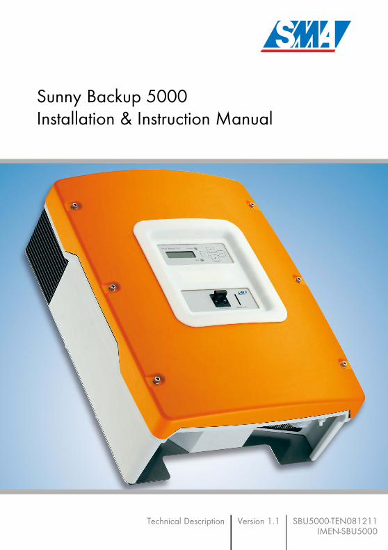
The Sunny Backup system is suitable for use in conjunction with all Sunny Boys andSunny Mini Centrals from SMA Technologie AG. The modular structure allows thesuitable construction of systems with a maximum consumer power of approximately 5kW to 100 kW. The Sunny Backup system can be integrated into new PV systeminstallations, and can also be retrofitted onto existing PV systems. Along with the Sunny Backup 5000 inverter and the automatic switching device, abattery is necessary as a short-term storage device, for reliable operation. During gridfailure, the battery has the task of correcting the imbalance between generation andconsumption. Whenever less energy is being generated than consumed (e.g. at night),
0 0 7 8 5 5 6kWh
ENTERENTER
ESCESC
Sunny Backup 5000
Sunny Backup 5000
GeneratorGeneratorcontactor
Grid/Stand-alone gridcontactor
0 0 7 8 5 5 6kWh
PV couplingcontactor
Automatic disconnectiondevice for PV systems
Switching device
Sunny Backup system
SunnyBackup5000
Battery
Referencecounter
PV feed-in counter
BetriebOperation
ErdschlussEarth FaultStörungFailure
Public grid
Loads
PV system

The Sunny Backup 5000 SMA Technologie AG
Page 12 SBU5000-TEN081211 Technical Description
the battery is discharged. Whenever more energy is being generated than consumed(e.g. during the day), the battery is charged. The intelligent battery management builtinto the Sunny Backup 5000 protects the battery from overcharging and deepdischarge. This ensures that the battery service life stipulated by the batterymanufacturer can be achieved.All regulation and control is performed by the Sunny Backup 5000. If the system is ingrid-parallel operation, the Sunny Backup 5000 ensures standard-compliant gridmonitoring and battery-preserving charging. The Sunny Backup 5000 is extremelyquick to detect any failure of the public grid, and sends the command to the switchingdevice to disconnect the system from the grid. After a maximum of 20 ms, the loads willbe already supplied with electricity again, from the battery. After a matter of seconds,the PV system switches to this stand-alone grid, and either powers the loads, or is usedfor recharging the batteries. The efficiency during charging, regardless of whether fromthe grid, or from the PV system, and during discharging, is up to 95 %. Due to the SunnyBackup 5000's very high overload capability of up to 8.4 kW for 60 seconds, and itsintegrated smooth startup, critical loads with very high start currents can also be startedsafely. Thus, over-dimensioning of the inverter is not necessary.
The automatic switching device is also available with an optional additional connectionfor an emergency power generator. Thus, the system's reliability of supply can beincreased further, and a smaller battery can be used. In this case, the Sunny Backup5000 also conducts the startup and synchronization of the emergency powergenerator, and connects it to the consumer grid with the switching device. Thegenerator now powers the loads, and charges the batteries. Once the batteries arecharged sufficiently, the Sunny Backup 5000 automatically stops the generator.Despite the complex functions of the Sunny Backup system, it can be installed andconfigured with ease. All special material required for installation is included in thedelivery. Additional sub-distribution units are generally not necessary. The safety andfuse protection concept on the consumer side, and that of the PV system, are generallynot impaired by the Sunny Backup 5000, and do not need to be adapted. All the settings required for operation can be quickly and easily programmed in sixsteps using the "Quick Configuration Guide". By employing the concept of centraloperation referred to as "Single Point of Operation", the parameters of a multi-phase
The Sunny Backup system meets all requirements of the VDE 0126-1-1 directive,which is necessary in Germany. The switching devices for PV feeding areimplemented redundantly, and are monitored. The safety of this system has beeninspected and certified by the German Professional Association for PrecisionEngineering and Electrotechnology.
The Sunny Backup system is only intended for use in TN grids!

SMA Technologie AG The Sunny Backup 5000
Technical Description SBU5000-TEN081211 Page 13
system are only set on the master device, and all other devices automatically adopt theconfiguration. The easy-to-understand menu navigation allows quick access to allimportant data, even while the system is running. An MMC/SD card providesuncomplicated system control, and thus makes any service work easier.
The Sunny Backup System can also be used to realise a decentralised grid stabilisation.This battery grid feed feature enables the user to feed power from the batteries into theelectrical grid when required. The feeding from the battery can be time-depedent orinitiated via a external dry contact, for example ripple control signal which is sent fromthe energy supplier.
The graphics on the next pages show the different wiring options (1-phase and 3-phase).
Always use the MMC/SD card to save data and events. This is necessary in orderfor SMA Technologie AG to be able to help you in the event of a fault.
Before using the battery grid feed feature, please contact your energy supplier inorder to verify the local standards.

The Sunny Backup 5000 SMA Technologie AG
Page 14 SBU5000-TEN081211 Technical Description
L N PEX2
X1
PE
N
L
X5
PE
N
L
X4
AC1 L
ComSyncOut
ComSync
In
ComSMAOut
Master
Automatic
SwitchBox
ComSyncIn
ComSyncOut
MStr/L
BackupVtgCur
SBU5000
Load
mete
rP
Vm
ete
r
PV
syste
m
BatTmp
DC
+ -
Battery
ENTERENTER
ESCESC
IslandSunny
SUNNY BACKUP
AUTOMATIC SWITCHBOX
PE
N
L
X6
Generator
Genera
tor
L
N
PE
Sunny Boy
BetriebOperation
ErdschlussEarth FaultStörungFailure
BetriebOperation
ErdschlussEarth FaultStörungFailure
BetriebOperation
ErdschlussEarth FaultStörungFailure
Single-phase Sunny Backup system
Battery temperature
Synchronization bus
Backup measurement
cable
Phase
Neutral conductor
Protective earth
Battery
Legend
PE
N
L3
L2
L1
X3Loads
Backup
loads
PE
N
L3
L2
L1
Public Grid
205 3
Reference
counter
205 3
PV
feed-in
counter
Equipotentialbondingbar
Foundationgroundingelectrode
N PE

SMA Technologie AG The Sunny Backup 5000
Technical Description SBU5000-TEN081211 Page 15
PE
N
L
X6
Genera
tor
Generator
L N PEX2
PE
N
L3
L2
L1
X1
PE
N
L
X5
ENTERENTER
ESCESC
IslandSunny
Automatic disconnectiondevice
PV coupling contactor
Isolation contactor
Grid isolation contactor
PE
N
L
X4 Sunny Boy
BetriebOperation
ErdschlussEarth FaultStörungFailure
PV
mete
rLoad
mete
r
Sunny Backup
PV
syste
m
Single-phase Sunny Backup system
I/O ComSyncIn
ComSyncOut
MStr/L1
SLV1/L2
SLV2/L3
Referencecounter
Power andmeasurementcables
Phase
Neutral conductor
Protective earth
Legend
PV feed-incounter
205 3
205 3
PE
N
L3
L2
L1
X3 Loads
Backup
loads

The Sunny Backup 5000 SMA Technologie AG
Page 16 SBU5000-TEN081211 Technical Description
L3 L2 L1 N PEX2
PE
N
L3
L2
L1
X3
PE
N
L3
L2
L1
X1
PE
N
L3
L2
L1
X5
PE
N
L3
L2
L1
X4
AC1 L N PE
ComSyncOut
ComSync
In
ComSmaOut
AC1L N PE
ComSyncOut
ComSync
In
ComSmaOut
AC1 L N PE
ComSyncOut
ComSync
In
ComSmaOut
Slave 2 Slave 1 Master
Automatic
SwitchBox
ComSyncIn
ComSyncOut
MStr/L1
SLV1/L2
SLV2/L3
BackupVtgCur
BackupVtgCur
BackupVtgCur
Public Grid
205 3
205 3
Loads
SBU5000
Backup
loads
Load
mete
rP
Vm
ete
r
PV
syste
m
BatTmp
DC
+ -BatTmp
DC
+ -BatTmp
DC
+ -
Battery
ENTERENTER
ESCESC
IslandSunny
ENTERENTER
ESCESC
IslandSunny
ENTERENTER
ESCESC
IslandSunny
SUNNY BACKUP
AUTOMATIC SWITCHBOX
PE
N
L3
L2
L1
X6
Generator
Genera
tor
L1
L2
L3
N
PE
Sunny Boy
BetriebOperation
ErdschlussEarth FaultStörungFailure
BetriebOperation
ErdschlussEarth FaultStörungFailure
BetriebOperation
ErdschlussEarth FaultStörungFailure
Three-phase Sunny Backup system
Battery temperature
Synchronization bus
Backup measurement
cable
Phase
Neutral conductor
Protective earth
Battery
Legend
Equipotentialbondingbar
Foundationgroundingelectrode
Reference
counter
PV
feed-in
counter

SMA Technologie AG The Sunny Backup 5000
Technical Description SBU5000-TEN081211 Page 17
PE
N
L3
L2
L1
X6
Genera
tor
Generator
L1 L2 L3 N PEX2
PE
N
L3
L2
L1
X1
PE
N
L3
L2
L1
X5
ENTERENTER
ESC
IslandSunny
ENTERENTER
ESC
IslandSunny
ENTERENTER
ESCESC
IslandSunny
Automatic disconnectiondevice
PV coupling contactor
Isolation contactor
Grid isolation contactor
PE
N
L3
L2
L1
X4 Sunny Boy
BetriebOperation
ErdschlussEarth FaultStörungFailure
PV
mete
rLoad
mete
r
Sunny Backup
PV
syste
m
Three-phase Sunny Backup system
I/O ComSyncIn
ComSyncOut
MStr/L1
SLV1/L2
SLV2/L3
Referencecounter
Power andmeasurementcables
Phase
Neutral conductor
Protective earth
Legend
PV feed-incounter
205 3
205 3
PE
N
L3
L2
L1
X3 Loads
Backup
loads

The Sunny Backup 5000 SMA Technologie AG
Page 18 SBU5000-TEN081211 Technical Description
2.2 At a GlanceThe following figure provides an overview of all control elements and connections ofthe Sunny Backup 5000:
LEDs showing deviceoperation (green above,red below)
Control buttons
MMC/SDcard
Display
AC connections DC connections
DC circuitbreaker
Additionalconnections

SMA Technologie AG The Sunny Backup 5000
Technical Description SBU5000-TEN081211 Page 19
2.3 Dimensions
ENTERESC
SunnyIsland Operation
FailureUtility interactive battery inverter
DC-Disconnect MMC/SD Card
235 mm
467 mm612 mm
230 mm
Upper edge of thedevice
Upper edgewall bracket
Display height
62 mm
700 mm
235 mm
215 mm105 mm

The Sunny Backup 5000 SMA Technologie AG
Page 20 SBU5000-TEN081211 Technical Description
2.4 Scope of Delivery Sunny Backup 5000The following elements are included:
A 1 Sunny Backup 5000 with housing cover
B 2 air grills
C 1 wall bracket
D 1 battery temperature sensor
E 5 M25 metric-thread cable screw connections
F 5 M25 nuts (adapter M32->M25)
G 2 metric-thread dummy plugs
H 2 3-pole print terminals (for connecting relays 1 & 2)
I 2 4-pole print terminals (for connecting battery temperature/electricitysensor)
K 1 RJ45 communication cable (black, 2 m) for internal communication(between several Sunny Backup 5000)
L 1 silicone tube 10 mm x 0.5 m
M 1 128 MB SD card
N 1 rubber plug for feed-through of one cable
O 2 rubber plugs for feed-through of two cables
P 2 M6 x 10 mm hexagon socket screws incl. M6 contact disksfor connecting the Sunny Backup 5000 to the wall bracket
128MB
SI5048-11:ED4206TB-SI5048
S u n n y Backup 5000I n s t a l l a t i o n s- und Bedienungsanleitung
Technische BeschreibungA u s g a b e 1 . 0
ENTER ENTER
ESC ESC
Island Sunny
Gewährleistungs- und Garantiebedingungen(Name des Gerätes):Bitte füllen Sie die folgenden Felder aus:
:
Typ:Seriennummer:Datum der Inbetriebnahme:Anschrift:InstallationsbetriebTyp:Seriennummer:Datum der Inbetriebnahme:
Anschrift:Installationsbetrieb
ENTERENTER
ESCESC
IslandSunny
A
2x B
K
D
M
5x F
5x E
2x I
2x PQ
2x H
N 2x O
C
2x GL

SMA Technologie AG The Sunny Backup 5000
Technical Description SBU5000-TEN081211 Page 21
2.5 Required Tools and ResourcesThe following tools are recommended for mounting and installing the Sunny Backup5000:
Q 1 installation and user manual
The scope of delivery of the Automatic Switch Box, and that of the battery, canbe found in these products' respective documentation.
Tools (not included in delivery)
Stripping pliers
Cable end sleeves
Drill
Drill (e.g. stone drill), Ø 10 mm
Torque wrench (4 Nm to 5.7 Nm) with flathead screwdriver adapters in thesizes 10/5.5/2.5 mm
Hexagon (allen) key, 3 mm to 8 mm
Cable knife
Combination pliers
Phillips screwdriver, PH1 and PH2
Cable
Open-end/ring wrenches or socket wrench in the sizes 10/19/24/30
Multimeter
Crimping tool for cable lugs (suitable for cable cross-sections of up to 70 mm²)
Flathead screwdriver, 0.4 x 2.5 mm/1.0 x 10 mm/1.0 x 5.5 mm
Diagonal cutting pliers
Spirit level
Ratchet
Ratchet extension
Material (not included in delivery)
Wall anchors for the wall bracket (e.g. SX 10)
Cable ties

The Sunny Backup 5000 SMA Technologie AG
Page 22 SBU5000-TEN081211 Technical Description
2.6 Accessories (Optional)The following accessories for the Sunny Backup 5000 are also available:• Separate fuse for the battery (SMA order number: "SI-BATFUSE-..."
Enables cable protection (used with strip fuse ...-SIBA-...) or disconnection withcable protection (used with NH fuse ...-NH01-...) of the Sunny Backup 5000 fromthe connected battery.
• Separate connection box for the battery (SMA order number: "SBU-Con.33-...")Enables connection of several batteries to several Sunny Backup 5000s (seesection 6.2.4 "Battery Connection Box (SBU-CON.33)" (Page 44)).
• Separate multicluster Piggy-Back (SMA order number: "MC-PB-...")Required in multicluster systems for communication between the mainmaster and the sub-masters.
SMA Technologie AG also offers an extensive range of products allowing you tocommunicate with the Sunny Backup 5000 to query data, and much more. Amongthese devices are:• Sunny WebBox• Sunny Sensor Box
The software for configuration of your inverter, and for reading and analyzing the data,can be found at the SMA Technologie AG website, at www.SMA.de, and can bedownloaded for free (see section 23 "Contact" (Page 183)).
2.7 SMA Products (Optional)The Sunny Backup 5000 can be used in conjunction with all PV inverters from SMATechnologie AG.
Ring cable lugs (with hole size for M8 screws)
Heat shrink tubing
Hexagon bolts, 8 × 60 mm, washers
Material (not included in delivery)

SMA Technologie AG The Sunny Backup 5000
Technical Description SBU5000-TEN081211 Page 23
2.8 Name Plate/Firmware VersionYou can identify the Sunny Backup 5000 from the name plate and firmware version.• The name plate is located on the left side of the housing.• You can read the firmware version of your device on the display using the
"312.02 FwVer" parameter (see section 19.3 "Diagnostics" (Page 154)).

The Sunny Backup 5000 SMA Technologie AG
Page 24 SBU5000-TEN081211 Technical Description

SMA Technologie AG Safety Instructions
Technical Description SBU5000-TEN081211 Page 25
3 Safety Instructions
3.1 Important Notes Regarding OperationPlease follow all operating and safety instructions in this manual. If these instructions areignored, a significant danger of injury or death arises and damage to the device,system or plant may also result. Carefully read through the safety instructions beforeinstalling and commissioning the device. Store the manual at an easily accessiblelocation.
Be sure to observe all applicable regional standards and guidelines.
The Sunny Backup 5000 may only be installed or opened by qualifiedpersonnel (qualified electrician).
Never attempt to repair the device yourself. Unprofessional repair workcan be dangerous. Please consult your dealer or SMA Technologie AG ifa fault occurs.
The operating consumption of the Sunny Backup 5000 discharges thebattery. In standby mode this load is about 4 W and in idle mode it isabout 25 W. Observe this when you wish to install the Sunny Backup5000, but do not wish to immediately use it.It may be necessary to set the Sunny Backup 5000 to Stop mode (seesection 9.3 "Deactivation" (Page 83) and disconnect it from the battery bymeans of the DC circuit breaker.
Safety Instructions SMA Technologie AG
Page 26 SBU5000-TEN081211 Technical Description
3.2 Potential HazardsLike any other power converter, the Sunny Backup 5000 is an electrical device thatpresents certain hazards when operated.
Life-threatening voltages and currents occur within the Sunny Backup5000. Complete protection against accidental contact is only providedwhen the following points are followed according to the handbook:• The device is mounted correctly.• The device is properly grounded.• All connections to the device are made correctly.• The housing cover is securely closed.
If this is ignored, a significant danger of injury and death arises anddamage to the device may also result.
Before performing any maintenance work or installation work on theSunny Backup 5000, you must make absolutely sure that all devices builtin or connected to the system are completely isolated from all voltagesources (battery, (stand-alone) grid, generator). Ensure that the systemcannot be accidentally switched on again. Proceed in the order givenbelow:• Switch off all loads.• Press and hold <ENTER> until the "Hold key to stop" message
appears.• Press and hold ENTER until the Sunny Backup 5000 stops and
"STANDBY–To start press <ENTER>" appears on the display.• Switch off the Sunny Backup 5000 using the DC circuit breaker and
also disconnect the device from the batteries (e.g. using the optionalSI-BattCase load disconnecting switch).
• Subsequently, disconnect the Sunny Backup 5000 from the AS-Box'sAC connection (line circuit breaker in the AS-Box).
• Make sure that the Sunny Backup 5000 has been disconnected fromall voltage sources.
• Wait at least five minutes to let the capacitors discharge and allowthe voltage inside the device to drop to a safe level. In order to fullydischarge, the capacitors require approximately 30 minutes. Makesure to avoid causing a short circuit on the DC side.
• Open the housing cover to ensure the device is not under voltage.

SMA Technologie AG Safety Instructions
Technical Description SBU5000-TEN081211 Page 27
The Sunny Backup 5000 can start on its own. When working on the stand-alone grid, ensure that ALL sources of AC and DC power in the systemhave been switched off (see above).
When touching the device, please note that some parts of the SunnyBackup 5000 housing heat up during operation. These temperatures mayexceed 60 °C. There is a danger of burn injury.
This device was NOT developed to power life-sustaining medical devices.The Sunny Backup 5000 may not be used in systems where a poweroutage could result in personal injury.
This device is suitable only for installation in enclosed spaces. Therefore,do not expose it to moisture, rain or direct sunshine (protection ratingIP30).
The Sunny Backup 5000 has been designed for use at elevations of up to 3000m above sea level. Please contact SMA Technologie AG before using the deviceat elevations above 3000 m.A performance loss of 0.5 % per 100 m is to be expected starting at an elevationof 2000 m above sea level!

Safety Instructions SMA Technologie AG
Page 28 SBU5000-TEN081211 Technical Description

SMA Technologie AG Installation
Technical Description SBU5000-TEN081211 Page 29
4 InstallationTake note of the required installation conditions listed below before mounting, installingand commissioning the Sunny Backup 5000 or the AS-Box.
4.1 Lifting/MovingThe Sunny Backup 5000 weighs 63 kg. Ensure that at least three people are availableto install the device. The Automatic Switch Box M weighs approximately 30 kg and the Automatic SwitchBox L weighs approximately 40 kg. Ensure that at least two people are available toinstall the device. The Automatic Switch Box XL weighs approximately 180 kg. It must be moved with apallet truck, forklift, or similar transport device designed for heavy loads.
4.2 UnpackingBefore installing the Sunny Backup 5000 and the Automatic Switch Box make sure thatall parts are included in the delivery.• Carefully check the packaging, the Sunny Backup 5000 and the Automatic Switch
Box for any signs of damage.• Ensure that all parts are included in the delivery (see section 2.4 "Scope of
Delivery Sunny Backup 5000" (Page 20)).• Enter the type and serial number of the device into the "Warranty and Guaranty
Conditions" form.• Keep the documents in a location where they will be easy to find later.
When selecting the installation location for Sunny Backup systems, you mustobserve the applicable building regulations. Installation in necessary stairwells orin other escape routes require consultation with the respective fire protectionauthority!
Always wear personal protective equipment (protective clothing, gloves,safety boots) to reduce the risk of injury.
The upper black ventilation flaps on the right and left side of the Sunny Backup5000 can be removed for transportation; carrying handles are located underthe flaps. The ventilation flaps are not mounted when the device is delivered. Theyare inserted after the device is installed (they snap on).

Installation SMA Technologie AG
Page 30 SBU5000-TEN081211 Technical Description
If something is missing or the Sunny Backup 5000 or the Automatic Switch Box has beendamaged during transport, contact SMA Technologie AG immediately. For moreinformation, please see section 23 "Contact" (Page 183).
4.3 Minimum Clearance Air enters the Sunny Backup 5000 through the undersideof the housing and then flows through the device beforeexiting through the air grills on top of the housing.When installing the device, a minimum clearance of 20cm at the sides and 10 cm above the housing must beprovided to ensure adequate ventilation of the SunnyBackup 5000.All external cables are connected through the undersideof the housing. This requires a minimum clearance of atleast 30 cm.Operation of the device and reading the display is mucheasier when the Sunny Backup 5000 is installed with thedisplay at eye-level with at least 50 cm clearance in front.
Remove the tape that covers both the outer and inner holes for the cable feed-throughs of the Sunny Backup 5000. It prevents foreign objects from entering thehousing during transport.
Keep the packaging in case you need to return the Sunny Backup 5000, theAutomatic Switch Box or their accessories.
When installing the Sunny Backup 5000 in smaller rooms, make sure thatadequate ventilation is available. The device produces heat when operating thatmust be removed.
Several Sunny Backup 5000s can be installed on top of each other without anyproblems since the active OptiCool ventilation system expels the heat to the side.The control of the integrated fans is temperature-dependent.
20 cm
30
cm
ENTERENTER
ESCESC
IslandSunny
50cm
10
cm
20 cm

SMA Technologie AG Installation
Technical Description SBU5000-TEN081211 Page 31
4.4 Wall Mounting
The Sunny Backup 5000 and Automatic Switch Box have considerable weight. Takethis into account when choosing the installation location and method of installation.Protect the Sunny Backup 5000 and the Automatic Switch Box from direct sunlight. Hightemperatures lead to lower performance of the battery inverter.
To make the job easier, we recommend usingthe supplied wall bracket to mount the SunnyBackup 5000 and using a spirit level toensure correct alignment. Fix the wall bracketusing three screws (8 mm diameter).
Do not install the Sunny Backup 5000 and the Automatic Switch Box• on flammable construction materials,• in areas where highly flammable materials are stored,• in potentially explosive areas!
Sunny Backup 5000 and the Automatic Switch Box may only be operatedhanging vertically. Since condensation can build up, horizontal operationis not permitted!
The ambient temperature must not be outside the -25 °C to +50 °C range.
ENTERENTER
ESCESC
IslandSunny

Installation SMA Technologie AG
Page 32 SBU5000-TEN081211 Technical Description
The following diagram shows in detail the spacing of the drill holes for installation ofthe wall bracket, and the minimum clearance for installation of two or more SunnyBackup 5000s. The two outer screws are used to keep the Sunny Backup 5000securely attached to the wall.
700 mm
235 mm
215 mm105 mm
Screws for securing the device in position

SMA Technologie AG Installation
Technical Description SBU5000-TEN081211 Page 33
Keep to the following sequence when mountingthe Sunny Backup 5000:• Mount the wall bracket (1). To mark the
positions to drill the holes, you can use thewall bracket as a drilling template.
• Now hang the Sunny Backup 5000 onto thewall bracket using its mounting plate so thatit cannot be moved sideways.
• Secure the Sunny Backup 5000 in positionby screwing the supplied screw onto the wallbracket.
• Insert the upper right and left air grills (theyonly need to be snapped on).Make sure that the Sunny Backup 5000 ispositioned securely on the bracket.
1

Installation SMA Technologie AG
Page 34 SBU5000-TEN081211 Technical Description
To fasten the Automatic Switch Box M or L tothe wall, please use four screws (8 mmdiameter).
Due to its weight, the Automatic Switch Box XL must be placed on the provided base(height 200 mm).
A ratchet with an extension (for fastening screws) makes the installation of theAutomatic Switch Box M or L easier.

SMA Technologie AG Installation
Technical Description SBU5000-TEN081211 Page 35
4.5 Installing Batteries
Batteries must be accommodated in protected rooms, and sufficient ventilation of theinstallation location must be ensured. For battery systems which are only connected toone or more Sunny Backup 5000s, there is sufficient protection against direct andindirect accidental touching. It is not necessary to install such batteries in a separatebattery room, or in a self-contained electrical facility.The necessary air volume flow for ventilation of the room which accommodates thebatteries is calculated as per EN 50272-2 under the following assumptions:• Nominal battery voltage = 48 V• Battery type: closed lead acid batteries (VRLA)• Max. charging voltage = 2.4 V/cell
Q = 0.0096 x C10 [m³/h]
with C10 as the 10 hour nominal capacity in [Ah].The cross-sectional area of the ventilation inlets and outlets is calculated according tothe following formula:
A = 28 x Q [cm2]
Observe the battery manufacturer's installation instructions, as provided with thebattery upon delivery, and the applicable standards and directives for installationof batteries (EN 50272-2).
Please observe all safety instructions of relevance to the battery. The mainones that apply here are:• Smoking prohibited! Do not allow open flames, embers, or sparks
near the battery - danger of explosion and fire.• Metal components of batteries are always energized. Therefore, do
not place foreign objects or tools on the battery. Work carried out onthe battery must always be performed with insulated tools - dangerof short-circuiting.
• The electrolyte is extremely corrosive. During normal operation, it isnot possible to accidentally touch the electrolyte. If the housingbecomes damaged, exposed bonded electrolyte is just as corrosiveas liquid electrolyte.

Installation SMA Technologie AG
Page 36 SBU5000-TEN081211 Technical Description
In the area near the battery, it is not always ensured that the explosive gases aresufficiently diluted. For this reason, a clearance distance is to be observed in which noequipment which causes sparks or smoldering is permitted.The clearance distance is calculated as follows:
d = 5.76 x (C10)1/3 [cm]
The following table indicates the necessary air volume flows, the ventilation cross-sectional areas, and clearance distances for various closed lead acid batteries.
The batteries can either be installed directly on the ground, or on a special batterymount.
Finally, install the battery bank in accordance with the installation instructions providedby the battery manufacturer.
Battery capacity [Ah]
Air volume flow for room ventilation [m³/h]
Ventilation cross-sectional area for natural air inlet and air outlet [cm²]
Clearance distance [cm]
100 Ah 0.96 m³/h 27 cm² 27 cm
142 Ah 1.36 m³/h 38 cm² 31 cm
284 Ah 2.72 m³/h 76 cm² 38 cm
426 Ah 4.08 m³/h 114 cm² 44 cm
For closed lead acid batteries (liquid electrolyte) with the same charging voltages,the ventilation requirements are about 5 times higher than those stipulated here.As closed lead acid batteries are generally charged with even higher chargingvoltages, the requirements increase even further.
With closed batteries, installation in an acid-resistant collecting tray is to beprovided for so that, in the event of a fault, leaking electrolyte cannot causefurther damage.

SMA Technologie AG Opening and Closing
Technical Description SBU5000-TEN081211 Page 37
5 Opening and ClosingDo not remove the Sunny Backup 5000's housing cover, or open the door of theAutomatic Switch Box, unless during installation of the device, or maintenance or repairwork.
5.1 Opening and Closing of the Sunny Backup 5000Opening the DeviceProceed as follows:1. Loosen the six hexagon socket screws on the front side of the Sunny Backup 5000,
in order to remove the cover.2. Remove the six hexagon socket screws.3. Carefully and evenly pull the housing cover until it comes free from the housing.4. Store the service access cover in a safe place while mounting, installing or
repairing the device.
Closing the Device
Before installing the housing cover of the Sunny Backup 5000, ensure that all cablesare properly laid and that all tools have been removed from within the housing (seesection 6 "Electrical Connection" (Page 39)).1. Starting from the front, place the cover evenly on the housing.2. Attach the housing cover onto the Sunny Backup 5000 using the six hexagon
socket screws. Tighten the screws evenly and firmly.
The Sunny Backup 5000 and the Automatic Switch Box may only beinstalled or opened by qualified personnel (qualified electrician). Switch off the Sunny Backup 5000 and disconnect it, along with theAutomatic Switch Box, from all voltage sources (battery, grid, generator)(see sections 9.2 "Stopping" (Page 82) and 9.3 "Deactivation" (Page 83)).Wait 5 minutes.Ensure that the system cannot be accidentally switched on again.
When closing the Sunny Backup 5000, make sure that the original tooth lockwashers are under the six hexagon socket screws. They secure the groundconnection of the cover.
Opening and Closing SMA Technologie AG
Page 38 SBU5000-TEN081211 Technical Description
5.2 Opening and Closing of the Automatic Switch BoxOpening the DeviceProceed as follows:1. Undo the two fasteners on the Automatic Switch Box door, using the (double-bit)
cabinet key provided, with a 90° turn to the right.2. Open the door.
Closing the DeviceBefore closing the Automatic Switch Box door, ensure that all cables are properly laidand that all tools have been removed from within the housing (see section 6 "ElectricalConnection" (Page 39)).1. Smoothly push the door closed.2. Close the two fasteners on the Automatic Switch Box door, using the (double-bit)
cabinet key provided, with a 90° turn to the left.
SMA Technologie AG Electrical Connection
Technical Description SBU5000-TEN081211 Page 39
6 Electrical Connection
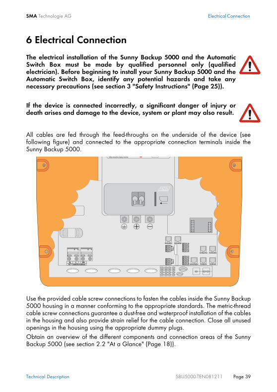
All cables are fed through the feed-throughs on the underside of the device (seefollowing figure) and connected to the appropriate connection terminals inside theSunny Backup 5000.
Use the provided cable screw connections to fasten the cables inside the Sunny Backup5000 housing in a manner conforming to the appropriate standards. The metric-threadcable screw connections guarantee a dust-free and waterproof installation of the cablesin the housing and also provide strain relief for the cable connection. Close all unusedopenings in the housing using the appropriate dummy plugs.Obtain an overview of the different components and connection areas of the SunnyBackup 5000 (see section 2.2 "At a Glance" (Page 18)).
The electrical installation of the Sunny Backup 5000 and the AutomaticSwitch Box must be made by qualified personnel only (qualifiedelectrician). Before beginning to install your Sunny Backup 5000 and theAutomatic Switch Box, identify any potential hazards and take anynecessary precautions (see section 3 "Safety Instructions" (Page 25)).
If the device is connected incorrectly, a significant danger of injury ordeath arises and damage to the device, system or plant may also result.

Electrical Connection SMA Technologie AG
Page 40 SBU5000-TEN081211 Technical Description
Detailed installation descriptions of the connections are provided in the followingsections: • Grounding (section 6.1)• DC connection (section 6.2)• AC connection (section 6.3)• Battery temperature sensor (section 6.4.1)• Communication for multi-device connection (section 6.4.3)• Multi-function relay 1 and 2 (section 6.4.4)• External communication (section 6.5)• GenMan connection (section 6.6)• Automatic Switch Box connection (section 6.7)
6.1 Grounding
The DC grounding conductors must be connected to the connection labeled "Ground".The grounding cable is installed in five steps:
In stand-alone configurations, the (protective) ground of the Sunny Backup 5000and its individual components must be wired as a TN grid only. All validstandards and guidelines must be taken into account!
Before commissioning the Sunny Backup 5000, it must be externallygrounded according to the relevant regulations. The N connection of the Sunny Backup 5000 has NOT been connectedwith PE by default. However, since a connection between N and PE isrequired for correct operation, this must be done outside of the device (seesection 6.7.3 "Supply Line (X1/Load Meter)" (Page 67)).
External grounding of the negative pole of the batteries is possible because thebatteries and the grid side are galvanically isolated within the Sunny Backup5000. In this case, make sure that the high currents that may occur under faultconditions can be adequately discharged.If a connection is required, then this must be made externally by an installer.

SMA Technologie AG Electrical Connection
Technical Description SBU5000-TEN081211 Page 41
1. Loosen the cable screw connection on the device.2. Thread the grounding conductor through the cable screw connection.3. Remove the protective insulation from the conductor and fit a suitable ring cable
lug to the exposed end of the conductor.4. Install the cable screw connection at the second cable feed-through from the right.
- Insert the metric-thread cable screw connection into the feed-through opening.- Screw the counter nut onto the cable screw connection thread inside the
housing and tighten it.5. Attach the conductor with the ring cable lug to the ground connection terminal and
tighten the screw firmly (torque 4.0 Nm to 5.7 Nm).
Calculating the Required Grounding Cable Cross-sectionSMA Technologie AG cannot calculate generally valid values for the required cross-section of the grounding cable for external grounding of the battery. The conductordimensions depend on the type and size of the battery connected, the external fuse (DCside) and the material used in the grounding conductor.
Exact calculation of the grounding conductor cross-section must take account ofthe regionally applicable standards and guidelines (e.g IEC 60364 ElectricalInstallation of buildings).

Electrical Connection SMA Technologie AG
Page 42 SBU5000-TEN081211 Technical Description
The required cross-section of a (copper) grounding conductor can be calculated usingthe following formula. Trigger times, e.g. for the integrated DC circuit breaker, of about25 ms are typical for short-circuit currents between 2000 A and 10000 A.
A grounding conductor of 16 mm² cross-section is thus adequate for short-circuitcurrents up to 10000 A.
6.2 DC Connection
6.2.1 Safety Precautions/ConditionsConnect a suitable battery to the DC side (see section 21 "Technical Data" (Page 175)).DC must be connected observing all valid regulations (e.g. DIN EN 50272-2, Safetyreguirements for secondary batteries und battery installations).
All safety and maintenance instructions provided by the batterymanufacturer must be heeded.
Use appropriate (insulated) tools for installation and wiring of thebatteries (danger of short circuits and arcing).
When connecting the battery, ensure that the cable has sufficient cross-section and that the connections have the correct polarity.
The battery cables should be as short as possible. Long cables and insufficientcable diameters reduce the system efficiency as well as the overload capabilities.Do not lay the battery feed cables under plaster or in armored plastic pipes. Largecurrents flow through the battery cables so that they can become very warm.
t = interruption time in secondsISC = maximum battery current (short-circuit current) in amperesS = conductor cross-section in mm²

SMA Technologie AG Electrical Connection
Technical Description SBU5000-TEN081211 Page 43
6.2.2 Cable ProtectionIf you connect the batteries to the Sunny Backup 5000 in a ground-fault proof, short-circuit proof manner, and if the maximum short-circuit current is lower than 10,000 A,you do not need any additional DC line circuit breakers. Otherwise, you should use anexternal battery fuse, e.g. SI BatFuse with 250 A, which should be installed as close tothe battery as possible.
6.2.3 ConnectionThere is a "DC —" and a "DC +" connection available for each ring cable lug (max.70 mm²) for the battery feed cables in the Sunny Backup 5000.
Install the DC connections in the following sequence:1. Loosen the cable screw connections on the device.2. Thread the conductors through the cable screw connections.3. Remove the protective insulation from each conductor and fit a suitable ring cable
lug to the exposed end of the conductor.4. Install the cable screw connections with the M32/M25 adapter piece (included
in delivery) for "DC —" at the middle cable feed-through, and for "DC +" at theright-hand cable feed-through.- Insert the metric-thread cable screw connection into the feed-through opening.

Electrical Connection SMA Technologie AG
Page 44 SBU5000-TEN081211 Technical Description
- Screw the counter nut onto the cable screw connection thread inside thehousing and tighten it.
5. Attach the "DC —" conductor with the ring cable lug to the "DC —" connection andtighten the retaining screw firmly (torque 4.0 Nm to 5.7 Nm).
Then attach the "DC +" conductor with the ring cable lug to the "DC +" connection andtighten the retaining screw firmly (torque 4.0 Nm to 5.7 Nm).
6.2.4 Battery Connection Box (SBU-CON.33)
The SBU-CON.33 allows you to connect several Sunny Backup 5000 devices andbatteries. For installation and connection, proceed as follows:1. Attach the provided wall mounts to the SBU-CON.33.2. Attach the SBU-CON.33 to the wall using suitable screws.3. Remove the nuts and locking washers from the required connection bolts.4. Feed the battery cables and Sunny Backup 5000 cables through the M32 screw
connections into the box, and attach them to the connection strips.
Only connect the external fuse/battery cables to the battery after all otherinstallation work is finished.
L+
M 32 IP 68V
D E
U
L M 32 IP 68V
D E
U
L M 32 IP 68V
D E
U
L M 32 IP 68V
D E
U
L M 32 IP 68V
D E
U
L M 32 IP 68V
D E
U
L
M32IP68V
DE
UL
M32IP68V
DE
UL
M32IP68V
DE
UL
M32IP68V
DE
UL
M32IP68V
DE
UL
M32IP68V
DE
UL
ENTERENTER
ESCESC
IslandSunny
ENTERENTER
ESCESC
IslandSunny
ENTERENTER
ESCESC
IslandSunny
L-L-
L+ L-

SMA Technologie AG Electrical Connection
Technical Description SBU5000-TEN081211 Page 45
5. Tighten the M10 conduit lugs with the prescribed torque (4.0 Nm to 5.7 Nm).6. Apply the provided dummy plugs to all unused screw connections.7. Tighten all screw connections.
Close the cover of the SBU-CON.33.
The maximum cable cross-section which can be fed into the SBU-CON.33 is 70 mm2.The maximum current-carrying capacity is 3 x 160 A.
Ensure that the polarity is correct - danger of short-circuiting.
If there are several batteries in one system, connection must occur via the SBU-CON.33.

Electrical Connection SMA Technologie AG
Page 46 SBU5000-TEN081211 Technical Description
6.3 AC ConnectionThe Automatic Switch Box is connected to AC1 at the Sunny Backup 5000, with a three-conductor connection (see section 6.7.4 "Sunny Backup 5000 (X2/Sunny Backup)"(Page 68)).
1. Sheathe the cable screw connection over the three-conductor cable and then insertthe conductor into the housing of the Sunny Backup 5000.
2. Install the M25 metric-thread cable screw connection (included in delivery) on the"AC1 – Loads/Sunny Boys" cable feed-through.- Insert the cable screw connection thread into the cable feed-through opening.- Screw the counter nut onto the cable screw connection thread inside the
housing and tighten it.3. Remove the protective insulation from each of the three wires.4. Install the three wires PE, N and L onto AC1: Following the specified sequence,
insert the appropriate wire into the appropriate PE, N or L "AC1 (Loads/SunnyBoys)" spring-type terminals.

SMA Technologie AG Electrical Connection
Technical Description SBU5000-TEN081211 Page 47
6.4 Additional ConnectionsFor installing the connections described below, feed the cables through the specifiedholes in the rubber terminal block. Plugs for sealing the RJ45 communication cable forinternal and external communication are provided in the rubber terminal block upondelivery. Combining plugs allows you to establish 0 to 4 feed-throughs (2 plugs withouta feed-through, 1 with 1 feed-through and 2 with 2 feed-throughs). Remove any of theseto connect the communication cable.
6.4.1 Battery Temperature SensorThe battery temperature sensor measures the temperature of the connected battery. Thisis necessary since the optimum charging voltage for a battery strongly depends on thetemperature. Further information is provided in section 14.4 "Charge Control" (Page117).
A battery temperature sensor is provided with each Sunny Backup 5000. Only onebattery temperature sensor, which is connected to the corresponding master, is requiredfor a cluster. (The terms "cluster", "master", and "slave" are defined in section 24"Glossary" (Page 184).)
A battery temperature sensor must be connected for operating the Sunny Backup5000 (included in the delivery).In case of a fault (short circuit, cable break), the Sunny Backup 5000 operates ina safe setting, which over time leads to insufficient battery charging. A warningindicating that the defective battery temperature sensor should be replacedimmediately is shown on the display.
Only use the battery temperature sensor provided with the delivery.Never drill any holes in any part of the battery to mount the sensor.
Fasten the battery temperature sensor to the outside of one of the battery cells.Select a location if possible between two cells, but near the middle of the batterybank as a whole, because this is where the most heat is produced duringoperation.

Electrical Connection SMA Technologie AG
Page 48 SBU5000-TEN081211 Technical Description
Proceed as follows when connecting the battery temperature sensor:
1. Pierce a hole in the rubber terminal area at the corresponding position.2. Starting from the outside, feed the cable with cable end sleeves through the hole.3. Insert one wire with the cable end sleeves in each of the "BatTmp" connection
terminals of the provided 4-pole print terminals and tighten the screws of theseterminals.
4. Insert the 4-pole print terminal into the "BatTmp" socket.
The polarity of the two conductors has no influence on the function of the batterytemperature sensor.

SMA Technologie AG Electrical Connection
Technical Description SBU5000-TEN081211 Page 49
6.4.2 Battery Current SensorIn addition to the internal measurement, the Sunny Backup 5000 provides the possibilityto measure the battery current via a shunt.
When connecting the battery current sensor proceed as follows:
1. Pierce a hole in the rubber terminal area at the appropriate position.2. Starting from the outside, feed the cable with the cable end sleeves through the
hole.
The battery current sensor is obligatory in case that DC generators and DCconsumers shall be connected. Only one battery current sensor connectedto the respective master is required for a cluster.
The battery current sensor must be looped around the negative pole of thebattery. The side of the shunt that is connected to the Sunny Backup 5000 mustbe connected to the "BatCur+" connection terminal.If the battery current sensor is connected as described above,• positive battery current means that the battery is discharging (current from
the battery)• negative battery current means that the battery is charging (current into the
battery)
Electrical Connection SMA Technologie AG
Page 50 SBU5000-TEN081211 Technical Description
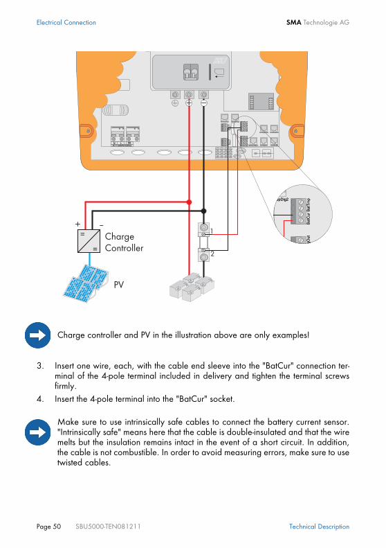
3. Insert one wire, each, with the cable end sleeve into the "BatCur" connection ter-minal of the 4-pole terminal included in delivery and tighten the terminal screwsfirmly.
4. Insert the 4-pole terminal into the "BatCur" socket.
Charge controller and PV in the illustration above are only examples!
Make sure to use intrinsically safe cables to connect the battery current sensor."Intrinsically safe" means here that the cable is double-insulated and that the wiremelts but the insulation remains intact in the event of a short circuit. In addition,the cable is not combustible. In order to avoid measuring errors, make sure to usetwisted cables.

SMA Technologie AG Electrical Connection
Technical Description SBU5000-TEN081211 Page 51
When connecting a battery current sensor to the Sunny Backup 5000 the device-internal offset must be set. This is only possible when you are in the installer level andthe Sunny Backup 5000 is in standby mode.
Proceed as follows:• Connect a short-circuit bridge (e. g. a piece of wire) to the "BatCur+" and "BatCur-
" terminals instead of your battery current sensor. • Use the "225.01 BatCurSnsTyp" parameter in order to set which type (None/
50mV/60mV) you will use. After a sensor type has been set (50 mV/60 mV) otherparameters (02, 03 and 04 in the menu 225# Battery Current Sensor) will be ac-tivated.
• Using the "225.02 BatCurGain60" and/or "225.03 BatCurGain50" parameterset the maximum current value of the battery current sensor used (e. g. 400 A/60 mV).
• Close and start the Sunny Backup 5000 as described in the manual.• Change to "225.04 BatCurAutoCal" and set "Start". The Sunny Backup 5000 con-
ducts an automatic calibiration.• Check the offset failure with the "120.06 TotBatCur" parameter. It should be (ap-
proximately) zero.• Open the Sunny Backup 5000. Remove the short-circuit bridge connected to the
"BatCur+" and "BatCur-" terminals. Connect the battery current sensor instead ofthe short-circuit bridge.
6.4.3 Communication for Multi-device ConnectionTo increase its performance, the Sunny Backup 5000 can be connected in a 3-phasesystem with other Sunny Backup 5000 devices. The devices communicate with eachother through an RJ45 communication cable.
The current shunt can be ordered from SMA (SMA order number „SI-SHUNTxxx“).
The RJ45 communication cable is a Cat5e-FTP patch cable.

Electrical Connection SMA Technologie AG
Page 52 SBU5000-TEN081211 Technical Description
Proceed as follows when installing the communication cable:
1. Remove the left of the two plugs in the rubber terminal area.2. Starting from the outside, feed the RJ45 cable through the hole.3. Insert the RJ45 plug into the "ComSyncOut" socket. The terminator plug remains in
the "ComSyncIn" socket.
Each Sunny Backup 5000 device is delivered with one black and one white RJ45communication cable.You require the black cable to establish (internal) communication between severalSunny Backup 5000 devices. If you only have one Sunny Backup 5000 in yourcluster, the cable is not required.The white cable is used for external communication (via RS232 or RS485), seealso section 6.5 "Interface for External Communication" (Page 58).
Make sure that you have selected a multi-phase configuration in the QuickConfiguration Guide (see section 8 "(First) Commissioning" (Page 77)).
ENTERENTER
ESCESC
IslandSunny
Master Slave 1 Slave 2
ENTERENTER
ESCESC
IslandSunny
ENTERENTER
ESCESC
IslandSunny
Termination resistors

SMA Technologie AG Electrical Connection
Technical Description SBU5000-TEN081211 Page 53
4. This cable goes into the "ComSyncIn" socket in the next Sunny Backup 5000. Anyother additional cable would be inserted into the "ComSyncOut" socket and leadto the next Sunny Backup 5000 (there in the "ComSyncIn" socket). When youhave completed this, insert the terminator plug into the "ComSyncOut" socket.
5. Wrap the rubber plug (depending on the number of cables with one or two feed-throughs, see 2.4 "Scope of Delivery Sunny Backup 5000" (Page 20)) around thecable.
6. Reinsert the plug in the opening provided in the rubber terminal block.
6.4.4 Multi-function Relay 1 and 2The Sunny Backup 5000 provides you with several options to control internal andexternal operations. For this purpose, two multi-function relays are integrated into thedevice with which you can assign functions via the menu 241# using the Rly1Op andRly2Op parameters (see section 16 "Relay" (Page 133)).
The relays are changeover contacts. They have both a break contact as well asa NO contact.The relay functions are listed as NO contact functions, in other words, the contactis closed if the relay is activated by selecting the function. For the exception "Alm"(alarm), the relay has a break function. This means that the relay is normallyactivated and opens the contact. It is only deactivated when a fault occurs andthen closes the contact (and thus activates a warning light, for example).
You can only assign one function to each relay. In clusters, the relays of the slavescan also be used. They are set using the master.

Electrical Connection SMA Technologie AG
Page 54 SBU5000-TEN081211 Technical Description
Proceed as follows when installing the relay connections:
1. Pierce a hole in the rubber terminal area at the corresponding position.2. Starting from the outside, feed the cable with cable end sleeves through the hole.3. Insert the wires with the cable end sleeves in the "Relay1" or "Relay2" connection
terminals of the provided 3-pole print terminals and tighten the screws of theseterminals. The pins have the following meaning:- NC: Normally closed (closed when in standby)- C: Contact (operating contact)- NO: Normally opened (open when in standby)
4. Insert the 4-pole print terminal into thecorresponding socket.
Information on the switching capacities of the relays is provided in section 21"Technical Data" (Page 175).
NC
NO
C

SMA Technologie AG Electrical Connection
Technical Description SBU5000-TEN081211 Page 55
Load SheddingThe Sunny Backup 5000 can automatically switch off loads to protect the batteries fromdeep discharge. To do so, an external (AC or DC) power contactor must be installedbetween the Sunny Backup 5000 and the loads (see also section 2.6 "Accessories(Optional)" (Page 22)).
Generator StartThe Sunny Backup 5000 can control generators. It supports generators that can bestarted and stopped by a single contact and generators that require more than onecontact (in combination with the optionally available generator manager (GenMan)).
If a relay is used for load shedding, the loads will no longer be supplied withelectricity in the event of a fault in the Sunny Backup system, even if the grid isavailable.
The two relays, which are integrated in the Sunny Backup 5000 and are freelyprogrammed, assume both tasks (depending on the programming in menu 261#,parameter Rly1Op and Rly2Op); see also section 16 "Relay" (Page 133).The AutoGn function is pre-configured for Relay1 and the AutoLodSoc function ispre-configured for Relay2.

Electrical Connection SMA Technologie AG
Page 56 SBU5000-TEN081211 Technical Description
6.4.5 BatVtgOut Power SupplyThe battery voltage is conducted to the outside at these terminals. The battery voltageis fused at both poles by PTC resistors (max. 0.75 A) and can fluctuate depending onthe battery status. This connection can, for example, be used to supply a DC contactorfor load shedding.
Proceed as follows when connecting the power supply:
1. Pierce a hole in the rubber terminal area at the corresponding position.2. Starting from the outside, feed the cable with cable end sleeves through the hole.3. Insert one wire with the cable end sleeves in each of the "BatVtgOut" connection
terminals of the provided 4-pole print terminals and tighten the screws of theseterminals.
4. Insert the 4-pole print terminal into the "BatVtgOut" socket.

SMA Technologie AG Electrical Connection
Technical Description SBU5000-TEN081211 Page 57
6.4.6 Digital Input, DigInThese terminals are used as a digital input, for example, the feedback contact for theGenMan (GenRn) is connected here.Proceed as follows when connecting the digital input:
1. Pierce a hole in the rubber terminal area at the corresponding position.2. Starting from the outside, feed the cable with cable end sleeves through the hole.3. Insert one wire with the cable end sleeves in each of the "DigIn" connection
terminals of the provided 4-pole print terminals and tighten the screws of theseterminals.
4. Insert the 4-pole print terminal into the "DigIn" socket.
For more information on connecting and operating the GenMan, please see thecorresponding product documentation.

Electrical Connection SMA Technologie AG
Page 58 SBU5000-TEN081211 Technical Description
6.5 Interface for External Communication
The communication interface is used to communicate with SMA communication devices(e.g. Sunny Boy Control, Sunny WebBox) or a PC with appropriate software (e.g.Sunny Data Control). Depending on the selected communication interface, up to 50inverters can be detected at once. Detailed information on this topic can be found inthe communication device manual, the software, or on the Internet at www.SMA.de.
Die following communication interfaces can be built into the Sunny Backup 5000:• RS232• RS485• RS485 & CAN
The RS485 & CAN Piggy-Back is necessary in order to construct larger systems withmore than one cluster. Only the master devices of each cluster require these Piggy-Backs.Alongside the CAN bus, which is solely responsible for communication between themaster devices, and for which RJ45 sockets are situated directly on the Piggy-Back, thisPiggy-Back performs the function of a normal RS485 Piggy-Back.
The detailed wiring diagram for the individual communication interfaces can be foundin the communication device manual. This wiring diagram includes the followinginformation:• Details on the required cable type• Which of the inverter's connections are used• Whether or not the communication cables must be terminated• Whether the protective earth needs to be connected to the cable shield
The next pages will describe the following:• The housing feed-throughs for the communication interface
Installation or replacement of the communication interface is only to becarried out by a qualified electrician.
Piggy-Backs are only required at the master device (single point of operation).
Communication via Powerline/Powerline modem (NLM) is not possible in SunnyBackup systems.

SMA Technologie AG Electrical Connection
Technical Description SBU5000-TEN081211 Page 59
• The permitted cable route in the Sunny Backup 5000• The location of the sockets for connecting the communication wires• The location of the interface port
6.5.1 Connection of the Interface
1. Remove the right plug of the two plugs in the rubber terminal area.2. Thread the cable through the cable feed-through (A) from the outside.3. Insert the cable into the upper socket.4. Place the plug around the cable.5. Reinsert the plug in the opening provided in the rubber terminal block (A).6. Lay the cable in area (B) as shown in the following figure.7. The three pins that you are to use are specified in the operating manual for the
communication device. The following table displays the assignment of thespecified pins for the pins of the RJ45 socket.
When opening the Sunny Backup 5000, follow all the safety instructionsas described in section 3.2 "Potential Hazards" (Page 26).
Electrostatic discharges are an acute danger to the Sunny Backup 5000 and tothe communication interface. Ground yourself by touching PE before removingthe communication interface from the packaging, and before touching anycomponents within the Sunny Backup 5000.
Read the communication device manual before beginning installation work.Further wiring details can be found there.
Communicationdevice pin (Sub-D 9-
pole)
RS232 RS485 RJ45 socket
2 RXD A (Data–) 3
3 TxD — —
5 GND GND 2
7 — B (Data+) 6

Electrical Connection SMA Technologie AG
Page 60 SBU5000-TEN081211 Technical Description
8. Terminate the Sunny Backup 5000 at RS485.In the Sunny Backup 5000, the RS485 data bus is terminated using a plug. Thisplug is already pre-installed in the Sunny Backup 5000. Please only remove theplug if you would like to connect another Sunny Backup 5000 device or acommunication device.
9. Plug the communication interface into the board (D).10. Close the Sunny Backup 5000 as described in section "Closing the Device" (Page
37).
On the circuit board above the RJ45 socket is a red sliding switch (C) with whichyou can switch from RS485 to RS232 communication. The default setting isRS485 (downward position).
A Housing feed-through in the base of the Sunny Backup 5000
B Cable route (gray surface)
C RS232 communication sliding switch
D Interface port
A B
DC

SMA Technologie AG Electrical Connection
Technical Description SBU5000-TEN081211 Page 61
6.5.2 Data Transmission SpeedThe Sunny Backup 5000 can communicate with external devices at a range of differentdata transmission speeds (1200 to 19200 bps). The "270.06 ComBaud" parametermust be set appropriately for this.
The Sunny Backup 5000 uses the SMA-Net protocol for communication.A detailed wiring diagram for the communication interfaces for the entirecommunication structure of your system can be found in the handbook for thecommunication device you have chosen.
If Sunny Boys are connected to the communication bus, then the baud rate mustbe set to 1200 bps (factory setting). Observe the manufacturer's specification forall other devices.

Electrical Connection SMA Technologie AG
Page 62 SBU5000-TEN081211 Technical Description
6.6 GenMan ConnectionWhen operating a Sunny Backup 5000 with GenMan, the following assignment of theinterfaces or signals applies:
Signal on GenMan Signal on Sunny Backup 5000
GenRq Relay1, AutoGn function (see 16 "Relay" (Page 133))
GenRn DigIn
The GenMan connection must occur at the master device!
For more information on connecting and operating the GenMan, please see thecorresponding product documentation.

SMA Technologie AG Electrical Connection
Technical Description SBU5000-TEN081211 Page 63
6.7 Automatic Switch Box ConnectionThe Automatic Switch Box is the central switching device of the Sunny Backup system.It is available in the following versions:• Automatic Switch Box M: for single-phase backup systems with one Sunny Backup
5000• Automatic Switch Box L: for three-phase backup systems with one Sunny Backup
5000 per phase• Automatic Switch Box XL: for three-phase systems with high output (multicluster
systems with up to four three-phase clusters).
All connection terminals for the external 400 V or 230 V AC cables are situated on thebottom row of the mounting plate. Only in the Automatic Switch Box XL are the X2 /Sunny Backup terminals and circuit breakers on the second level above the bolt clamps.The terminals are implemented either as spring-type terminals, or as bolt clamps,depending on the model. Some cables are also connected to fuse holders or line circuitbreakers, which are also accommodated on the terminal strip.All cables, except for the communication cables, are fed into the Automatic Switch Boxfrom underneath. For this purpose, a plastic flange plate with membranes is situated onthe underside of the housing. For the fully assembled communication cables (with RJ45plugs), a number of plug feed-throughs are provided in the side panel.
6.7.1 Feeding in the Energy CablesTo feed in and connect the 400 V or 230 V AC cables, proceed as follows:• Select a feed-through opening which is suitable for the cable diameter, and strip
away a length of the cable's outer sheath which corresponds to the length to beinstalled in the AS-Box.
• Use a sharp pin-shaped object to prick a hole in the rubber membrane at the feed-through position. Do not cut it with a knife, or with diagonal cutting pliers.
• Thread the prepared cable through the opening in the elastic membrane which isthus created. The membrane must tightly reseal around the cable sheath.
• Provide sufficient strain relief for the cable outside the Automatic Switch Box.• Route the conductors to the connection terminals, and strip the cable end
according to the connection type. For spring-type terminals, you do not need cableend sleeves, even with multi-strand or fine-strand cables. However, observe thestipulated length to be stripped (13–15 mm with 6 mm² spring-type terminals, and18–20 mm with 16 mm² spring-type terminals).
Make sure that the feed-throughs used are tightly sealed, and that allunused feed-throughs are closed.

Electrical Connection SMA Technologie AG
Page 64 SBU5000-TEN081211 Technical Description
• Connect the conductors to the provided connection terminals. For bolt clamps(only in Automatic Switch Box XL), you must first squeeze a conduit lug onto thestripped cable end before you can make these connections. Observe thetightening torque for bolt clamps (6–12 Nm).
6.7.2 Feeding in the Control and Measurement CablesThe control cables and measurement cables (hereinafter referred to as communicationcables) which are provided with the Automatic Switch Box, and which have RJ45 plugsattached, are to be fed into a separate plug feed-through in the housing's side panel.
For a single-phase system, you require two cables (one black and one red); for a three-phase system (with three or more Sunny Backup 5000s), you need four cables (oneblack and three red).
To feed in and connect these communication cables, proceed as follows:• Loosen the pre-mounted plug feed-through at the hexagon socket screws on the
inside of the side panel, pull off the metal retaining bracket, and completelyremove the feed-through element through the installation opening.
• Loosen the two screws on the feed-through element, and separate the two plasticcomponents. In so doing, take care not to lose the loose rubber inserts, or theclamped-in plastic rods.
• The cables which are to be fed through must now be inserted (maximum three perfeed-through) into the rubber inserts at the provided locations (rounded areas inthe plastic components), with sufficient lengths of cable to reach from the feed-throughs to the appropriate connection points (RJ45 sockets on the circuit board).Insert the provided plastic rods to seal unused cable feed-throughs.
• Use cable ties to fasten the cables to the toothing provided at the feed-through.• Place the two plastic components around the rubber inserts and screw them
together.
The communication cables with plugs must not be fed through the plasticflange plate on the underside of the housing, even if this still has freemembranes. Threading the plug through would cause the membrane tobe widened excessively, and there would no longer be a tight sealaround the thinner cable.Do not feed the communication cables through the cable channel with 400V or 230 V AC cables.
If the length of the provided cables is insufficient, use commercially availableCat5e FTP cables (single shield) with gold contacts.

SMA Technologie AG Electrical Connection
Technical Description SBU5000-TEN081211 Page 65
• Now feed the cables through the installation opening into the Automatic SwitchBox until the feed-through element protrudes into the installation opening.
• From the inside, push the feed-through's opposing retainer into the plugged-through element's corresponding slot, and refasten the assembly to the side panelusing the hexagon socket screws.
• Take care not to route the communication cables directly beside 230 V AC cables.• Route the cable ends to the RJ45 sockets on the circuit board, and insert the plugs
into the appropriate sockets (see sections 6.7.10 "ComSync CommunicationCable" (Page 72) and 6.7.11 "BackupVtgCur External Control Lines andMeasurement Cables" (Page 72)).
The following diagram shows the connection plan of a three-phase system with a cluster(three Sunny Backup 5000s) at the Automatic Switch Box L. The individual cableconnections are described in detail in the subsequent sections.

Electrical Connection SMA Technologie AG
Page 66 SBU5000-TEN081211 Technical Description
The Automatic Switch Box M differs from the diagram in that at terminal strips X2,X4, X5 and (if applicable) X6, instead of connections L1, L2 and L3, there is onlyone connection L. The AS-Box XL differs from the diagram in that at terminal stripX2, four of each of the connections L1, L2, L3, N and PE are present (for up tofour Sunny Backup 5000 clusters, i.e., for up to twelve devices). The connectionterminal strip X6 is only present on Automatic Switch Boxes which were orderedwith a generator connection (order option, cannot be retrofitted).
L3 L2 L1 N PEX2
PE
N
L3
L2
L1
X3
PE
N
L3
L2
L1
X1
PE
N
L3
L2
L1
X5
PE
N
L3
L2
L1
X4
AC1 L N PE
ComSyncOut
ComSync
In
ComSmaOut
AC1L N PE
ComSyncOut
ComSync
In
ComSmaOut
AC1 L N PE
ComSyncOut
ComSync
In
ComSmaOut
Slave 2 Slave 1 Master
Automatic
SwitchBox
ComSyncIn
ComSyncOut
MStr/L1
SLV1/L2
SLV2/L3
BackupVtgCur
BackupVtgCur
BackupVtgCur
Public Grid
205 3
205 3
Loads
SBU5000
Ba
cku
plo
ad
s
Lo
ad
me
ter
PV
me
ter
PV
syste
m
BatTmp
DC
+ -BatTmp
DC
+ -BatTmp
DC
+ -
Battery
ENTERENTER
ESCESC
IslandSunny
ENTERENTER
ESCESC
IslandSunny
ENTERENTER
ESCESC
IslandSunny
SUNNY BACKUP
AUTOMATIC SWITCHBOX
PE
N
L3
L2
L1
X6
Generator
Ge
ne
rato
r
L1
L2
L3
N
PE
Sunny Boy
BetriebOperation
ErdschlussEarth FaultStörungFailure
BetriebOperation
ErdschlussEarth FaultStörungFailure
BetriebOperation
ErdschlussEarth FaultStörungFailure
Three-phase Sunny Backup system
Battery temperature
Synchronization bus
Backup measurement
cable
Phase
Neutral conductor
Protective earth
Battery
Legend
Equipotentialbondingbar
Foundationgroundingelectrode
Reference
counter
PV
feed-in
counter

SMA Technologie AG Electrical Connection
Technical Description SBU5000-TEN081211 Page 67
6.7.3 Supply Line (X1/Load Meter)Connect the X1 / Load Meter (L1, L2, L3, N, PE) connections to the system's electricitymeter. The required cross-section of the cables depends on the upstream fuse outsidethe Automatic Switch Box. The maximum permissible back-up fuse is 63 A (forAutomatic Switch Boxes M and L) or 160 A (for Automatic Switch Box XL). Cables withcross-sections of up to 16 mm² can be connected to the Automatic Switch Boxes M andL via spring-type terminals; the Automatic Switch Box XL has M8 bolt clamps for ringcable lugs and cable cross-sections of up to 70 mm².
Three phases can also be routed to the loads via the Automatic Switch Box in single-phase backup systems (Automatic Switch Box M only) (see section 6.7.5 "ConsumerSystem (X3/Backup Loads)" (Page 68)). In this case, also implement a three-phasesupply line connection. If no three-phase loads are connected, you only require the gridconnection at L1.
When connecting the phase conductors to the connection terminals L1, L2and L3 in three-phase systems, make sure that, on the grid side, they forma clockwise phase sequence in the specified sequential order. Check thisbefore commissioning the system.
The Sunny Backup system is only intended for use in TN grids!
Do not install an RCD in the backup system's grid-side supply cable! Itsprotective function (voltage disconnection) would be cancelled out by thebackup system, and it would also interrupt the neutral conductor's groundconnection.
Make sure that in the backup system's supply line, there is no switchingelement which interrupts the neutral conductor. The backup systemrequires a grounded neutral conductor. There must always be a groundconnection, as otherwise, in stand-alone operation, a TN grid would nolonger be formed, so other protective measures would be necessary.
Make sure that the PEN conductor on the grid side is grounded within thesystem (before or at the point of separation into N and PE conductors),e.g., connection from the house connection box to the equipotentialbonding bar.

Electrical Connection SMA Technologie AG
Page 68 SBU5000-TEN081211 Technical Description
6.7.4 Sunny Backup 5000 (X2/Sunny Backup)Connect the X2 / Sunny Backup connection to the Sunny Backup 5000 inverter(s). Inthe Automatic Switch Box, every inverter connection is fused by a C 32 A line circuitbreaker. This affects the required cable cross-section, as does the layout type.
In a multicluster backup system (Automatic Switch Box XL), several Sunny Backup 5000inverters are to be connected per phase. With this variant, no spring-type terminals arepresent in the Automatic Switch Box for connection of the phases. In this case, pleaseattach the conductors directly to the corresponding line circuit breakers. These areassigned to terminal strip X2, and are labeled with phase identifiers.
6.7.5 Consumer System (X3/Backup Loads)The output cable for the consumer system is routed via fuses in the Automatic SwitchBox. Connect the phase conductors to the fuses' screw terminals which are assigned toterminal strip X3 and which are labeled with phase identifiers. In terminal strip X3,spring-type terminals are provided for neutral and protective earth conductors.The fuses are necessary in order to protect the output cable from overload in stand-alone grid operation. Note that in this case, the Sunny Backup 5000 inverters and thePV system can power the loads, and the upstream fuse on the grid side has no effect inthis situation. Therefore, check the cable cross-section of the consumer system's supplycable, determine the required fuse size according to layout type and ambientconditions, and install appropriate fuse plugs.
SMA Technologie AG recommends that the cable to the inverter have a cross-section of 6 mm² (e.g. 3 x 6 mm²), as this is sufficient for all layout types with thefuse protection mentioned above.
In multi-phase systems (Automatic Switch Boxes L and XL), it is imperativeto ensure correct assignment of devices. The phases L1, L2 and L3 mustform a clockwise phase sequence on the grid side. This must be ensuredfor the connection X1 (grid) and, if applicable, X6 (generator). Whenconnecting the cables to the Sunny Backup 5000, assign the device whichis configured as "master" to phase L1, the device configured as "slave 1"to phase L2, and the device configured as "slave 2" to phase L3.
Connect just one inverter to each output (line circuit breaker).

SMA Technologie AG Electrical Connection
Technical Description SBU5000-TEN081211 Page 69
Three phases can also be routed via the Automatic Switch Box in single-phase backupsystems (Automatic Switch Box M only). This means that also the phases L2 and L3 arerouted through the grid isolation contactor, and in the event that the backup system isdisconnected from the grid, they are also disconnected from the grid. However, feedingfrom the PV system, the Sunny Backup inverter and, if applicable, the diesel generator,occurs only via phase L1.
6.7.6 PV System (X4/PV System)Connect your PV system to the connection terminal strip X4 / PV System. Due to themultitude of possible constellations (e.g. one inverter per phase, or several smallinverters in parallel), the Automatic Switch Box is not intended to serve as a distributorcabinet and fuse box for the PV inverters.The line circuit breakers (and, if applicable, RCD) prescribed in the manuals of theinverters used must be installed between the Automatic Switch Box and the PV inverters.Thus, the Automatic Switch Box only contains one single-phase or three-phase cableconnection (L/N/PE or L1/L2/L3/N/PE). In Automatic Switch Box M, cables with a cross-section of up to 6 mm² can beconnected to the spring-type terminals; in Automatic Switch Box L, a cross-section of upto 16 mm². In Automatic Switch Box XL, bolt clamps are available for larger cross-sections (up to 70 mm²).
The fuse plugs are not provided on delivery as they must be dimensionedspecifically according to the respective system. For the Automatic Switch BoxesM and L, you require D02 fuse plugs; for Automatic Switch Box XL, you requireNH00 fuse plugs.Note the maximum permissible values as listed here: 35 A (Automatic Switch BoxM), 63 A (Automatic Switch Box L) and 160 A (Automatic Switch Box XL).
In unfavorable constellations, it may occur that it is not possible to select whetherto install the fuses as upstream or downstream fuses. This is unavoidable due tothe complexity of the backup system with several feeding sources.
Make sure that no three-phase loads (e.g. continuous-flow heaters, or 5-pole CEE plug sockets) are connected to the Automatic Switch Box's phaseL1, unless the corresponding L2 and L3 phase conductors are alsoconnected. Otherwise, in the event of grid failure, single-phase feeding ofthe three-phase load would occur, and thus a risk of personal injurywould arise, as phases L2 and L3, which are not disconnected from thegrid, would be feeding voltage into the grid in an improper manner! Ifonly phase L1 is routed from the Automatic Switch Box to the loads, it mayonly be connected to single-phase loads.

Electrical Connection SMA Technologie AG
Page 70 SBU5000-TEN081211 Technical Description
The dimensioning of the output cable is to be selected according to the routingconditions and the upstream fuse on the grid side (see also X5 / PV Meter connection).For backup systems with a generator connection (order option), attention must also bepaid to the fuse protection of the generator feed-in. If the generator feed-in at the X6 /Generator terminal strip has a greater fuse protection than the supply cable from thefeed-in counter (upstream of X5 / PV Meter), then the output cable from X4 / PV Systemmust be implemented with this higher fuse value.With regard to short-circuit protection, the PV inverters and the Sunny Backup invertersdo not need to be taken into account as, due to their design, they cannot endanger thecables if a short circuit occurs. In the event of a short circuit, only short-circuit currentsfrom the grid, or from the diesel generator, require fuse protection. Overload protectionis always guaranteed if, as can be assumed, the cables which you route to the PVsystem are designed for at least the feed-in power of the PV system.
Only PV inverters, and no other feed-in generators, may be connected tothe X4 / PV System terminal strip if the Automatic Switch Box is connectedvia X5 / PV Meter to a feed-in counter which is tariffed for PV power. It isalso not allowed to connect loads to the X4 / PV System terminal strip, orto the cable which runs from this terminal strip to the PV system.

SMA Technologie AG Electrical Connection
Technical Description SBU5000-TEN081211 Page 71
6.7.7 PV Feed-in Counter (X5/PV Meter)Connect the X5 / PV Meter connection to the feed-in counter for the PV system. Thecross-section of the cables depends on the upstream fuse. Cables with cross-sections ofup to 6 mm² can be connected to the Automatic Switch Boxes M and L; the largestpermissible back-up fuse is 35 A.It is not necessary to include a protective earth (PE) conductor in this cable, as theAutomatic Switch Box is already connected to the system's equipotential bondingsystem with a larger cross-section, via grid connection X1 (Load Meter). If the supplycable from the feed-in counter includes a protective earth conductor, this can also beconnected to the PE terminal at X5 / PV Meter.Short circuit the connector X5/PV-Meter and X1/Load-Meter for the operation of a PV-system without feed-in meter (see figure below).
6.7.8 Generator (X6/Generator)Connect the X6 / Generator connection with the diesel generator's connection box.With the Automatic Switch Box M, a single-phase generator (L/N/PE) can beconnected; with the other models, a three-phase generator (L1/L2/L3/N/PE) can beconnected. The connections L, or L1, L2 and L3 are situated on fuse sockets beside theX6 / Generator terminal strip. Spring-type terminals are available for neutral andprotective earth conductors.Select the required cable cross-section according to the generator's nominal output, andaccording to whether the generator has an output fuse. With the fuse, or fuses, to beinserted in the Automatic Switch Box, you protect the cable leading to the generator
0 0 7 8 5 5 6kWh
ENTERENTER
ESCESC
Sunny Backup 5000
Sunny Backup 5000
GeneratorGeneratorcontactor
Grid/Stand-alone gridcontactor
0 0 7 8 5 5 6kWh
PV couplingcontactor
Automatic disconnectiondevice for PV systems
Switching device
Sunny Backup system
SunnyBackup5000
Battery
Referencecounter
PV feed-in counter
BetriebOperation
ErdschlussEarth FaultStörungFailure
Public grid
Loads
PV system
0 0 7 8 5 5 6kWh
Grid/S
Autodev
eferenceounter

Electrical Connection SMA Technologie AG
Page 72 SBU5000-TEN081211 Technical Description
against short-circuit currents from the grid, and against overload. Note that the ratingof the fuse in the generator output can also have an influence on the rating of the cableleading to the PV system (see section 6.7.6 "PV System (X4/PV System)" (Page 69)).
6.7.9 Signal-controlled feeding (X7/Feed In Signal)The grid feeding from the battery can, among other things, be controlled by anexternal, dry contact. This signal is send, for example, by the energy supplier and canbe received with a ripple control signal receiver. Connect the output of the ripplecontrol signal receiver to the “Feed In Signal” connection terminal of the AutomaticSwitch Box (0 = no feed in; 1 = feed in). Set the "232.41 FedInMod" parameter to“Signal”. Once the dry contact is closed, the Sunny Backup 5000 starts feeding theelectricity (see also section 13.7 "Grid feeding from the battery" (Page 112).
6.7.10 ComSync Communication CableThe Automatic Switch Box is controlled by the Sunny Backup 5000 via a CAN bus. Inmulti-phase systems (Automatic Switch Box L), this occurs via the inverter which isconfigured as master; in multicluster backup systems (Automatic Switch Box XL), thisoccurs via the inverter which is configured as master of the main cluster.Connect the ComSyncOut socket on the circuit board in the Automatic Switch Box tothe Sunny Backup 5000's ComSyncIn socket, using the black RJ45 cable provided (seesection 6.5 "Interface for External Communication" (Page 58)).
6.7.11 BackupVtgCur External Control Lines and Measurement CablesThe Automatic Switch Box transfers voltage measurement signals and currentmeasurement signals to the Sunny Backup 5000. In three-phase systems, each of thethree inverters receives the signals relevant to the phase with which it operates. Inmulticluster backup systems (Automatic Switch Box XL only), these signals are to berouted to the main cluster's devices.
If the diesel generator does not have an output fuse, you must implement the cableconnection to the Automatic Switch Box in a ground-fault proof and short-circuitproof manner. Alternatively, it is advisable (especially if the cable routes are long)to use an additional fuse box near the generator.
The CAN bus must be terminated at both ends with terminating plugs. For thispurpose, the ComSyncOut socket on the circuit board in the Automatic SwitchBox is already provided with a terminating plug ex works. In single-phasesystems, the other end of the bus is situated at the connected Sunny Backup 5000,while in three-phase systems it is at the inverter which is configured as slave 2 ofthe main cluster.

SMA Technologie AG Electrical Connection
Technical Description SBU5000-TEN081211 Page 73
Connect the socket Mstr / L1 on the circuit board in the Automatic Switch Box to theSunny Backup 5000's BackupVtgCur socket, using the red RJ45 cable provided (seesection 6.5 "Interface for External Communication" (Page 58)). In three-phase systems,the inverter to use for this connection is the inverter connected to phase L1, which mustalso be configured as master.In three-phase systems, use one of the provided red RJ45 cables to also connect thesocket Slv1 / L2 on the circuit board in the Automatic Switch Box to the BackupVtgCursocket at the Sunny Backup 5000 which is connected to phase L2, and which isconfigured as slave 1, and also connect the socket Slv2 / L3 on the circuit board in theAutomatic Switch Box to the BackupVtgCur socket at the Sunny Backup 5000 which isconnected to phase L3, and which is configured as slave 2. In multicluster backupsystems, these devices must be those of the main cluster.
6.7.12 Concluding TasksCheck that all feed-throughs are tightly sealed, and that no unsealed openings remain.Make sure that all of the cables which have been fed into feed-throughs are strain-relieved, and that the communication cables within the Automatic Switch Box cannotcome into contact with stripped 230 V conductors.For the power cables and measurement cables in three-phase systems, make sure thatthe phase sequences of the inverter connections match.Install all necessary fuses, and close the Automatic Switch Box.
Take care not to mix up the cables. Any cables which have the same colorare to be labeled at both ends before routing so as to avoid confusionwhen making the connections. If the phase sequence is connectedincorrectly, the grid and the inverters form different rotating fields, whichcauses short circuits upon activation.
When routing cables between a Sunny Backup 5000 and the Automatic SwitchBox, only permanent cable installation and strain-relieved cables are permissible.Use sheathed cables (doubly insulated conductors)!

Control Elements SMA Technologie AG
Page 74 SBU5000-TEN081211 Technical Description
7 Control ElementsIn order to commission the Sunny Backup 5000, you should familiarize yourself with itsoperation beforehand. The individual control elements can be seen in the followingfigure.
7.1 Display MessagesThe Sunny Backup 5000 display has two lines each with 16 characters. For details,please see section 10.6 "Display Messages (Overview)" (Page 96).
7.2 DC Circuit BreakerThe DC circuit breaker is used to switch on/off as well as disconnect the Sunny Backup5000 on the DC side. For details, see section 9 "Activation and Deactivation" (Page81).
ENTERESC
SunnyIsland Operation
FailureUtility interactive battery inverter
DC-Disconnect MMC/SD Card
Display
DC circuit breaker
Buttons
MMC/SD card
LEDs
����������������
� ��� �������
Output power/charging power
Direction of energyflow and system status
Status of ext. sourcesDevice assignmentRelay2 status
Warning
Load status
Relay1 statusGrid status

SMA Technologie AG Control Elements
Technical Description SBU5000-TEN081211 Page 75
7.3 ButtonsThe table explains the button functions of the Sunny Backup 5000:
7.4 Meaning of the Light-emitting Diodes (LEDs)In the Sunny Backup 5000 control panel, there is both a green (above) and a red(below) light emitting diode (LED). Their functions are described in the table:
7.5 MMC/SD CardThe Sunny Backup 5000 features an MMC/SD card which can be used for updatingfirmware and as a service interface. For details, please see section 11 "Archiving Dataon an MMC/SD Card" (Page 101).
Button Functions
cancels the selected functionanswers NOnavigates one menu level higher
navigates up one list elementincreases data value
navigates down one list elementdecreases data value
selects functionselects data valueconfirms the changeanswers YESnavigates one menu level lowerstarts device (when held pressed down)stops device (when held pressed down)
Green LED Red LED Operating mode
— — standby or off(no inverter operation)
ON — in operation
— ON failure or fault
ON ON initialization

Control Elements SMA Technologie AG
Page 76 SBU5000-TEN081211 Technical Description

SMA Technologie AG (First) Commissioning
Technical Description SBU5000-TEN081211 Page 77
8 (First) Commissioning
8.1 Requirements
The Quick Configuration Guide (QCG) allows you to quickly and easily commissionyour Sunny Backup 5000. To do so, use the menu to select the 'right' system for you.The display then shows a selection via which the parameters can be set specifically.
8.2 Starting the Quick Configuration Guide (QCG)
The QCG is automatically activated during the initial startup of the device.
Before beginning with the commissioning, ensure that all electrical connectionshave the correct polarity and make sure that everything is connected accordingto the instructions in section 6 "Electrical Connection" (Page 39).
Always use the MMC/SD card to save data and events. This is necessary in orderfor SMA Technologie AG to be able to help you in the event of a fault.
When starting the QCG, useful parameter values are set as default settings!
1. Switch on the Sunny Backup 5000 by switching the DC circuit breaker to the"ON" position.
2. The Sunny Backup 5000 starts the startup phase. Waitfor the following displays.
When starting the Sunny Backup 5000 for the first time, the QCG is automaticallyactivated. Please continue reading in point 6. Otherwise, follow this list.
SIBFSBOOT V1.000
SMA SMA SMA SMA
SMA SMA SMA
SBU5000
@SMA 2007
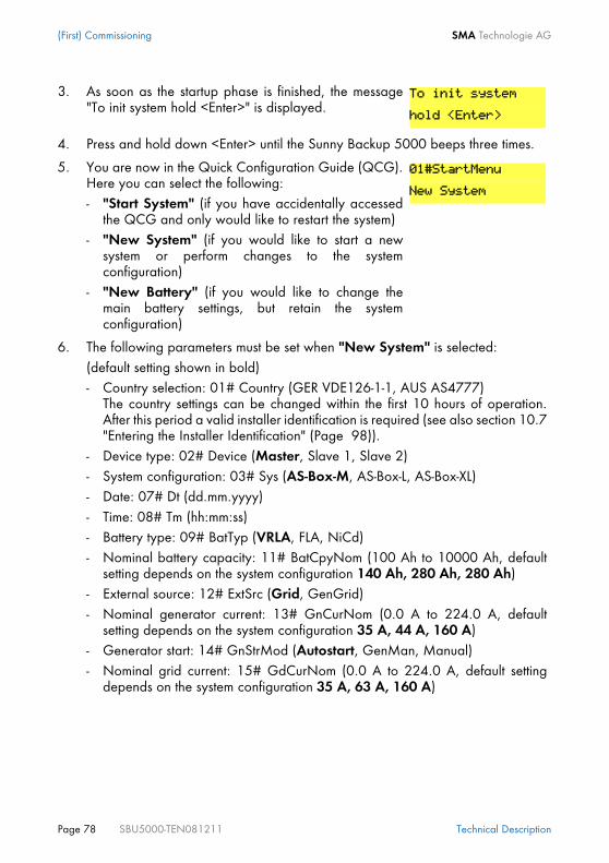
(First) Commissioning SMA Technologie AG
Page 78 SBU5000-TEN081211 Technical Description
3. As soon as the startup phase is finished, the message"To init system hold <Enter>" is displayed.
4. Press and hold down <Enter> until the Sunny Backup 5000 beeps three times.
5. You are now in the Quick Configuration Guide (QCG).Here you can select the following:- "Start System" (if you have accidentally accessed
the QCG and only would like to restart the system)- "New System" (if you would like to start a new
system or perform changes to the systemconfiguration)
- "New Battery" (if you would like to change themain battery settings, but retain the systemconfiguration)
6. The following parameters must be set when "New System" is selected:(default setting shown in bold)- Country selection: 01# Country (GER VDE126-1-1, AUS AS4777)
The country settings can be changed within the first 10 hours of operation.After this period a valid installer identification is required (see also section 10.7"Entering the Installer Identification" (Page 98)).
- Device type: 02# Device (Master, Slave 1, Slave 2)- System configuration: 03# Sys (AS-Box-M, AS-Box-L, AS-Box-XL)- Date: 07# Dt (dd.mm.yyyy)- Time: 08# Tm (hh:mm:ss)- Battery type: 09# BatTyp (VRLA, FLA, NiCd)- Nominal battery capacity: 11# BatCpyNom (100 Ah to 10000 Ah, default
setting depends on the system configuration 140 Ah, 280 Ah, 280 Ah)- External source: 12# ExtSrc (Grid, GenGrid)- Nominal generator current: 13# GnCurNom (0.0 A to 224.0 A, default
setting depends on the system configuration 35 A, 44 A, 160 A)- Generator start: 14# GnStrMod (Autostart, GenMan, Manual)- Nominal grid current: 15# GdCurNom (0.0 A to 224.0 A, default setting
depends on the system configuration 35 A, 63 A, 160 A)
To init system
hold <Enter>
01#StartMenu
New System

SMA Technologie AG (First) Commissioning
Technical Description SBU5000-TEN081211 Page 79
The following parameters must be set when "New Battery" is selected:(default setting shown in bold)- Battery type: 08# BatTyp (VRLA, FLA, NiCd)- Nominal battery voltage: 09# BatVtgLst (42 V to 48 V)- Nominal battery capacity: 10# BatCpyNom (100 Ah to 10000 Ah)
If you have a system with more than one Sunny Backup 5000 device, you mustfirst run the QCG on the slave(s) before starting the master device (displaymessage "INIT MASTER OK START?"). Only the device type is set there. Onlystart the master device thereafter!
If the "New Battery" option is selected, only specific battery settings are reset andset to new values. System settings are not affected.
7. After entering the parameters listed below, the displayof the master shows the following message:
8. Press <ENTER> to confirm. The following message thenappears on the display.
9. Keep the <ENTER> button pressed. A beep is heard, theSunny Backup 5000 starts and is operating.
If only one Sunny Backup 5000 is used in the system, the device type is set to"Master" and is not displayed.
If the device unexpectedly displays an error, it must be remedied before thedevice can be operated. For this purpose, refer to section 20 "Troubleshooting/Problem Solving" (Page 159).
For more details on the adjustable parameters, please see section 19 "ParameterLists" (Page 141).Note that you must first enter the installer password before some parameters canbe changed (see section 10.5 "Entering the Installer Password" (Page 94)). Inaddition, some parameters can only be changed in standby mode (see section9.2 "Stopping" (Page 82)).
INIT MASTER OK
START?
STNDBY:To Start
INV hold <ENTER>

(First) Commissioning SMA Technologie AG
Page 80 SBU5000-TEN081211 Technical Description

SMA Technologie AG Activation and Deactivation
Technical Description SBU5000-TEN081211 Page 81
9 Activation and Deactivation
9.1 Activation / Startup
This step assumes that the Sunny Backup 5000 has been checked for• correct (electrical) connections,• voltages and polaritiesand has already been put into operation by qualified personnel (qualifiedelectrician).
1. Switch on the Sunny Backup 5000 by switching the DCcircuit breaker to the "ON" position.
2. The Sunny Backup 5000 starts the startup phase. Waitfor the following displays.
As soon as the startup phase is finished, the message "To initsystem hold <Enter>" is displayed.
3. If you would like to access the QCG, press and hold<Enter> until the Sunny Backup 5000 beeps three times.Then the following display message appears (on how toproceed further, see section 8.2 "Starting the QuickConfiguration Guide (QCG)" (Page 77)).
4. If you do not press <ENTER> within 5 seconds, theSunny Backup 5000 skips the QCG and shows thefollowing message.
Start the slaves before you start the master device.
SIBFSBOOT V1.000
SMA SMA SMA SMA
SMA SMA SMA
SBU5000
@SMA 2007
To init system
hold <Enter>
01#StartMenu
New System
STNDBY:To Start
INV hold <ENTER>

Activation and Deactivation SMA Technologie AG
Page 82 SBU5000-TEN081211 Technical Description
9.2 StoppingProceed as follows to set the Sunny Backup 5000 to standby mode:
5. After the device has been switched on, the slaves showthe following message on the display.
6. Hold <ENTER> pressed down and the remaining time isshown using bars on the display.
7. Then the following message appears (until the masterstarts).
Even with the "270.01 AutoStr" parameter set, the Sunny Backup 5000 must bemanually started each time the device is switched on using the DC circuit breaker.
8. Press <ENTER> on the master device. A beep is heard, the Sunny Backup 5000starts and is operating. The green (upper) LED is illuminated.
If the device unexpectedly displays an error, it must be remedied before thedevice can be operated. For this purpose, refer to section 20 "Troubleshooting/Problem Solving" (Page 159).
1. Press <ENTER> to stop the Sunny Backup 5000. Thefollowing message appears.
2. Hold <ENTER> pressed down and the remaining time isshown using bars on the display.
3. The Sunny Backup 5000 has been stopped and thedisplay shows the following message:
Note that in standby mode there is still voltage present in the device (DCand AC1), and there may be a grid voltage through-connection.
STNDBY:To Start
INV hold <ENTER>
Hold to start...
Ready
Wait for Master
Hold to stop...
Hold to stop...
STNDBY:To Start
INV hold <ENTER>

SMA Technologie AG Activation and Deactivation
Technical Description SBU5000-TEN081211 Page 83
9.3 DeactivationTo switch off the Sunny Backup 5000, proceed as follows:1. Set the Sunny Backup 5000 to standby mode (see section 9.2 "Stopping" (Page
82)).2. Switch the DC circuit breaker of the Sunny Backup 5000 to the "OFF" position.
9.4 Disconnecting the Device from Voltage Sources1. Switch off the Sunny Backup 5000 (see section 9.3 "Deactivation" (Page 83)).2. Disconnect the Sunny Backup 5000 from the battery.3. Then disconnect the Sunny Backup 5000 from all voltage sources (switch off
power for AC1 and disconnect it).4. Make sure that the Sunny Backup 5000 has been disconnected from all voltage
sources.5. Wait at least five minutes to let the capacitors discharge and allow the voltage
inside the device to drop to a safe level.6. The Sunny Backup 5000 is now completely free of voltage and you can open it.
Even in standby mode, the Sunny Backup 5000 still requires about 4 W of powerfrom the battery.
You can only ensure that all internal meter readings/values are saved by usingthis switching sequence.
You must wait at least 30 seconds before reactivating the device, otherwiseproper operation of the Sunny Backup 5000 cannot be guaranteed.

Activation and Deactivation SMA Technologie AG
Page 84 SBU5000-TEN081211 Technical Description
9.5 Reactivating the Device Following Automatic Shutdown
To reactivate the Sunny Backup 5000 after it has switched off due to a battery beingtoo deeply discharged, proceed as follows:1. Switch off the DC circuit breaker.
2. After waiting for one minute, switch on the Sunny Backup 5000 by switching theDC circuit breaker to the "ON" position.
3. Now, continue as described in 9.1 "Activation / Startup" (Page 81).
4. Check that the Sunny Backup 5000 switches to charge mode.5. Check that all other energy generators in your system are also working correctly.
A complete shutdown indicates that components of the backup system orthe Sunny Backup 5000 have failed or are not working correctly due toincorrect parameter settings. Check the backup system for possible faults,both before and after reactivating the system, to avoid a completeshutdown in the future.
You must wait at least one minute to allow the capacitors to completelydischarge before switching the DC circuit breaker on again.
If, in rare cases, the device cannot be switched back on, wait a little longer andtry it again. This may result due to component tolerances.
After reactivation, it is important that the batteries are charged. If the grid isavailable again, the grid will recharge the batteries after a few minutes.
If the Sunny Backup 5000 immediately switches to battery preservation modeafter reactivation (see section 14.5 "Battery Preservation Mode" (Page 121)),check the availability of the grid, and the functionality of the Automatic SwitchBox.The loads can be reconnected once the Sunny Backup 5000 enters charge mode.A precondition for this is that a generator capable of providing the requiredpower is connected, or that the grid is available.

SMA Technologie AG Operation
Technical Description SBU5000-TEN081211 Page 85
10 OperationThe main menu consists of a Home Screen and theother main menu items where branches can becreated in the sub menus. Operating modes aredisplayed on the Home Screen, e.g. the currentoperating mode, performance, etc. (see section10.6 "Display Messages (Overview)" (Page 96)).The menu consists of a main menu and maximumtwo submenu levels (see also the figure in section10.1 "Menu Structure" (Page 87)).Use the up and down arrow buttons to navigatethrough the menu levels. The cyclical arrangement(wrap around) allows you to scroll both forwardand backwards to access the desired menu asquickly as possible.
Once you have reached the desired menu, press <ENTER> to access the menu. Use<ESC> to exit the menu and navigate one level higher.
If you would like to access submenu 7, go backwards starting from 1 andcontinue past 9, instead of going six steps forwards.
You can skip menu entries. This takes place depending on the level of yourpassword. It ensures that all parameters in the user level that may only bechanged by the installer are skipped. The menu numbers are fixed, that meansthey do not change if an entry (or several entries) are skipped.
If you do not press any buttons for more than five minutes (inactivity), the HomeScreen is automatically displayed.
After a brief period of inactivity, the background illumination of the displayswitches off. You can switch the background illumination back on by pressing oneof the four buttons. No settings are changed when you press the button, this onlyactivates the display illumination.
The beeping function is always activated by default. To deactivate it, set the"270.04 BeepEna" parameter to off.
ENTERESC
SunnyIsland Operation
FailureUtility interactive battery inverter
DC-Disconnect MMC/SD Card

Operation SMA Technologie AG
Page 86 SBU5000-TEN081211 Technical Description
The Sunny Backup 5000 utilizes an operation concept referred to as "Single Point ofOperation". For a system with more than one device, all entries are made on themaster. There you configure the entire system, confirm events, warnings as well as errorsin the QCG (see section 8 "(First) Commissioning" (Page 77)) and update your firmwarewhen required (see section 11.6 "Firmware Update" (Page 106)).Exception: When starting the device for the first time, you must set the slave in the QCGand everything else is performed at the master.
Slave devices must wait for commands from the master devices. The followingmessage appears during this time.
Ready
Wait for Master
Single Point of Operation also means that all data, including the slave data, aresaved at the master device on the MMC/SD card.
In multicluster operation, the operation concept „Single Point of Operation“only ever applies within a cluster.
Messages can be displayed at any time while the device is in operation and theyhave priority over the Home Screen display.

SMA Technologie AG Operation
Technical Description SBU5000-TEN081211 Page 87
10.1 Menu Structure
The menu structure is divided into two levels:• User level• Installer level
The menus allowing system parameters to be changed can only be reached afterentering the installer password (see section 10.5 "Entering the Installer Password" (Page94)). These menu parameters can be used to monitor and control the Sunny Backup5000 in normal daily operation.
Configuration and changes to system parameters may only be performedby qualified personnel (qualified electrician)

Operation SMA Technologie AG
Page 88 SBU5000-TEN081211 Technical Description
111# Inverter Total Meters112# Inverter Device Meters
210# Inverter Settings
Battery
240# Relay Settings
250# System Settings260# Password Setting
220# Settings
230# Backup Settings
310# Inverter Diagnosis
330# Backup
320# Battery Diagnosis
Diagnosis
510# Operation Inverter520# Battery530# Operation Backup
Operation
540# Operation Generator550# Operation MMC
131# Total Meters132# Grid State133# Generator State134# Device Meters
241# Relay General242# Relay Load243# Relay Timer
311# Total System Diag312# Inverter Device Diag
Home Screen100# METERS
200# SETTINGS
300# DIAGNOSIS
400# HISTORY
500# OPERATION
600# DIRECT ACCESS
331# Grid Diag332# Generator Diag
231# General232# Grid Control233# Generator Control234# Generator Start235# Authentification
221# Battery Property222# Battery Charge Mode223# Battery Protect Mode224# Battery Silent Mode
110# Inverter Meters
120# Battery
130# Backup
Meters
Meters
150# Compact Meters
410# Failures Current420# Failure History430# Event History
Select Name:Select Number:

SMA Technologie AG Operation
Technical Description SBU5000-TEN081211 Page 89
Furthermore, the menu structure is divided into five different main menus withcorresponding submenus.Display values (Meters): The "100# Meters" main menu displays the most importantvalues in the first submenu:• Sunny Backup 5000 ("110# Inverter Meters")• Battery ("120# Battery Meters")• Backup system ("130# Backup Meters")• Compact messages ("150# Compact Meters")There are additional submenus or individual parameters (e.g. "120.02 BatVtg"parameter) on the following second menu level.Settings: Under the main menu "200# Settings" are several submenus allowing varioussystem parameters to be viewed and changed:• Sunny Backup 5000 ("210# Inverter Settings")• Battery ("220# Battery Settings")• Backup system ("230# Backup Settings")• Relay ("240# Relay Settings")• System ("250# System Settings") • Password entry ("260# Password Setting")Diagnosis: Under the main menu "300# Diagnosis" are several submenus allowingvarious system parameters to be viewed:• Device data ("310# Inverter Diagnosis")• Battery data ("320# Battery Diagnosis")• Backup system data ("330# Backup Diagnosis")Lists (History): Under the main menu "400# History" are several submenus allowingvarious lists to be viewed:• Present failures ("410# Failures Current")• Warnings and faults ("420# Failure History")• Events ("430# Event History")Functions in operation: Under the main menu "500# Operation" are severalsubmenus allowing various system parameters to be viewed or changed:• Inverter ("510# Operation Inverter")• Battery ("520# Operation Battery")• Backup ("530# Operation Backup")• Generator ("540# Operation Generator")• MMC/SD card ("550# Operation MMC")Direct Access: Under the menu "600# Direct Access", you have direct access tosettings and display values.

Operation SMA Technologie AG
Page 90 SBU5000-TEN081211 Technical Description
10.2 Changing ParametersUsing the up and down arrow buttons, you navigate through a selected menu (seefigure in section 10.1 "Menu Structure" (Page 87)) to view or change a parameter, forexample. When the relevant parameter appears on the display, you can read itspresent value.An arrow next to the value indicates that the parameter can be changed. If you press <ENTER>, the arrow begins to blink and you can change this parametervalue using the up/down arrow buttons.
As soon as the desired value appears on the display, press <ENTER> to save the newvalue.Then select Y(es) or N(o) by pressing the up/down arrow buttons to accept or rejectthe changes.Afterwards, press <ENTER> again to end the operation and continue working.
The Sunny Backup 5000 displays a corresponding message for parameters that canonly be changed in standby mode or require a different password level.
The increment (speed) of the change increases if you hold the button presseddown.
Note that some parameters can only be changed when the device is in standbymode (see section 9.2 "Stopping" (Page 82)). You can find the parameters forwhich this applies in the tables in section 19.2 "Adjustable System Parameters"(Page 145) and 19.5 "Functions in Operation" (Page 156).
Display Meaning
Incorrect password level, you cannot make any changes inthe menus. This is explained in section 10.5 "Entering theInstaller Password" (Page 94).
This parameter can only be changed in standby mode. Stopthe Sunny Backup 5000 to change the parameter (seesection 9.2 "Stopping" (Page 82)).
No permission to
change the value
Stop device to
change the value

SMA Technologie AG Operation
Technical Description SBU5000-TEN081211 Page 91
10.3 Direct AccessIn the menu "600# Direct Access", you have direct access to selected parameters viathe name, or to all parameters via the number.Via the Select Name submenu, you have direct access to the following functions:• ManChrgSel: manual initiation of an equalization charge (see section 14.4.3
"Equalization Charge" (Page 120))• BkupTst: initiation of a backup system test (see section 18.7 "Sunny Backup System
Test" (Page 140))• GnManStr: manual activation of the generator (see section 15.2.1 "Manual
Generator Operation" (Page 125))
Via the Select Number menu, you have direct access to every parameter by enteringthe parameter number.
10.4 Compact MetersIn this special menu, the Sunny Backup 5000 simultaneously displays a maximum offour values. This menu is primarily intended to facilitate the commissioning for theinstaller. There is a total of seven different compact meters.
Using the menu 600#, you can select the "222.01 BatChrgCurMax" parameter,for example, to set the maximum battery charging current.The direct access must be entered as a five-digit number, for example, 24101.Here, the first 3 digits describe the menu number and the last two describe theparameter number.Once the parameter has been set, you exit the setting. Using <ESC>, you returnto Direct Access and you can make additional changes there.
You can select the different displays of the compact meters using the up/downarrow buttons. Here, you can also use the "Wrap Around" function.The displays are always shown from the upper left to the lower right.

Operation SMA Technologie AG
Page 92 SBU5000-TEN081211 Technical Description
Bat1 (battery values 1)
Bat2 (battery values 2)
Inv (AC values of inverter)
InvTot (total AC values of inverter)
Ext (backup AC values)
BatTmp: battery temperature
BatSocErr: estimated error of the charge state
TotBatCur: total battery current of cluster
Name of the compact meter
BatSoc: battery charge state
����� ����� ��
� �������� �����
AptTmRmg: remaining absorption time
BatChrgVtg: nominal value of charging voltage
BatChrgOp: active charging process
BatVtg: battery voltage of device
Name of the compact meter ����� ����� ��
����������������
InvPwrRt: reactive power on the inverter
InvFrq: frequency on the inverter
InvPwrAt: effective power on the inverter
Name of the compact meter
InvVtg: voltage on the inverter
!"��������� �#$
%� ��&'�� ��&��(
Total reactive power of inverter (cluster)
Total effective power of inverter (cluster)
Name of the compact meter !")���%� �&'
%� �&��(
*+��������� �#$
%� �&'��%� �&��(ExtPwrRt: reactive power of ext. source
ExtFrq: frequency of ext. source
ExtPwrAt: effective power of ext. source
Name of the compact meter
ExtVtg: voltage of ext. source

SMA Technologie AG Operation
Technical Description SBU5000-TEN081211 Page 93
ExtTot (total backup AC values)
OpStt (inverter and generator status)
*+)���%� �&'
%� �&��(Total reactive power of ext. source (Cluster)
total effective power of ext. source (Cluster)
Name of the compact meter
GnStt: generator state
InvOpStt: operating mode
Name of the compact meter,-.��������/�!
,00
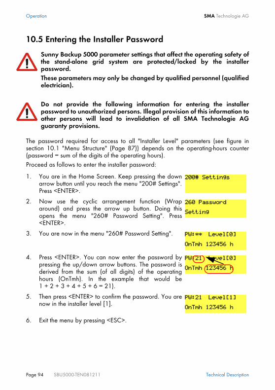
Operation SMA Technologie AG
Page 94 SBU5000-TEN081211 Technical Description
10.5 Entering the Installer Password
The password required for access to all "Installer Level" parameters (see figure insection 10.1 "Menu Structure" (Page 87)) depends on the operating-hours counter(password = sum of the digits of the operating hours).Proceed as follows to enter the installer password:
Sunny Backup 5000 parameter settings that affect the operating safety ofthe stand-alone grid system are protected/locked by the installerpassword.These parameters may only be changed by qualified personnel (qualifiedelectrician).
Do not provide the following information for entering the installerpassword to unauthorized persons. Illegal provision of this information toother persons will lead to invalidation of all SMA Technologie AGguaranty provisions.
1. You are in the Home Screen. Keep pressing the downarrow button until you reach the menu "200# Settings".Press <ENTER>.
2. Now use the cyclic arrangement function (Wraparound) and press the arrow up button. Doing thisopens the menu "260# Password Setting". Press<ENTER>.
3. You are now in the menu "260# Password Setting".
4. Press <ENTER>. You can now enter the password bypressing the up/down arrow buttons. The password isderived from the sum (of all digits) of the operatinghours (OnTmh). In the example that would be1 + 2 + 3 + 4 + 5 + 6 = 21).
5. Then press <ENTER> to confirm the password. You arenow in the installer level [1].
6. Exit the menu by pressing <ESC>.
200# Settings
260 Password
Setting
PW:** Level[0]
OnTmh 123456 h
PW:21 Level[0]
OnTmh 123456 h
PW:21 Level[1]
OnTmh 123456 h

SMA Technologie AG Operation
Technical Description SBU5000-TEN081211 Page 95
If the password is not valid, the Sunny Backup 5000 does not switch into theinstaller level. In this case, recalculate and re-enter the installer password asdescribed in this section.The installer level is switched back to the user level if• the Sunny Backup 5000 is switched off and on again (see section 9
"Activation and Deactivation" (Page 81)),• specific parameters are entered (e.g. the "510.01 InvRs" parameter) that
cause a restart,• an incorrect password is entered and if• no buttons are pressed for a period of 5 minutes.

Operation SMA Technologie AG
Page 96 SBU5000-TEN081211 Technical Description
10.6 Display Messages (Overview)The display has two lines each with 16 characters. The first line displays the menunumber and the menu name or where applicable, parameter name. The menu name issupplemented or the added text is displayed (e.g. parameter value) in the lower line,if required.The following message is displayed in the Home Screen:
In the upper line, a bar graph displays the total output or charging power.A character to the right of the graph indicates the load status: Here, "]" stands fornominal output. If the nominal load is exceeded, the character appears as ">". The direction of energy flow and the system status are displayed on the left in the lowerline. Here, the symbols stand for the generator side ("generator/grid"), for "battery"and for load side ("loads/Sunny Boys"). The arrows between the symbols indicate thedirection of energy flow.The symbol represents a power pole. The symbol to the right of this indicates whetherthe grid parameter ( ) or the offgrid parameter (x) is activ. The device assignment follows (master or slave, e.g. M1 or S1).Next to this assignment, the status of the external sources is indicated with the followingsymbol meanings:* Generator voltage and frequency are within the set limits.? Generator voltage and/or frequency are outside of the set limits. The Sunny
Backup 5000 will not connect the generator to the stand-alone grid whilethis situation exists.
! The maximum permissible generator reverse power has been exceededand the Sunny Backup 5000 disconnected the generator from the stand-alone grid.
The following letters indicate why the generator was requested:B(attery) Generator has been requested as a result of the battery charge level.L(oad) Generator has been requested as a result of the load-dependent generator
request.
����������������
� ��� �������
Output power/charging power
Direction of energyflow and system status
Status of ext. sourcesDevice assignmentRelay2 status
Warning
Load status
Relay1 statusGrid status

SMA Technologie AG Operation
Technical Description SBU5000-TEN081211 Page 97
S(tart) Generator has been requested by the operator manually setting thegenerator request in the Sunny Backup 5000 from "Auto" to "Start". Thegenerator is then NO LONGER controlled or switched off automatically bythe Sunny Backup 5000.
T(ime) Generator was started for 1 hour via the "Run1h" setting at the SunnyBackup 5000. Once this time has passed, the Sunny Backup 5000automatically switches off the generator.
The messages for both relays (filled in circle = activated / open circle = deactivated)follows in the lower line.The line ends with a warning display (!). This symbol blinks until you have viewed thewarning in the menu "410# Failures Current" or "420# Failure History".If faults occur, the device switches into standby mode and shows the fault on thedisplay. The fault must be remedied and then confirmed. The Sunny Backup 5000 canbe restarted thereafter.In the Home Screen, the Sunny Backup 5000 also shows the following values insuccession (in 3-second intervals: parameter name and parameter value) in the upperline:• Bar graph for output power or charging power (the direction of energy flow is
displayed by the arrows in the lower line)• Total effective power of inverter (cluster)• Effective power of external source (all phases)• Present battery charge state (SOC)• Counters (always one of five possibilities, depending on priority)
- remaining absorption time- remaining generator warm up time- remaining generator time of Run1h- remaining time of Timer1
The generator status and the reason for the request are shown on the displayalternatively under "status of external sources".
If, for example, the display changes every 3 seconds from "*" to "B", this meansthat the generator voltage and frequency lie within the specified limits and that thegenerator was requested as a result of the battery charge level.
If the generator has been manually set to "Stop", then no generator statusinformation is shown on the display. The field remains empty.

Operation SMA Technologie AG
Page 98 SBU5000-TEN081211 Technical Description
- remaining time of Timer2• Active charging processThe display of the lower line remains as previously described.
10.7 Entering the Installer Identification
To enter this into the Sunny Backup 5000, you must proceed as follows:
Depending on the situation, the values that are shown alternatingly on the displayare either shown or hidden. That means that if no generator is connected, nogenerator values appear on the display.
On the slave devices, only the bar graph is displayed for output power orcharging power and in the lower line, the device assignment (e.g. S1 for slave 1)and where applicable, the status of external sources (*, for a description, pleasesee further above) are displayed.
Some safety-related parameters regarding the SMA grid guard are speciallyprotected, and cannot be altered with the normal installer password. In order toadjust these grid monitoring parameters, you must request your individual SMAgrid guard password on the SMA Hotline.
1. Use the arrow buttons to get to the menu"200# Settings". Press <ENTER>.
2. Enter the installer password as described in section 10.5 "Entering the InstallerPassword" (Page 94).
3. Use the arrow buttons to get to the menu "230# BackupSettings". Press <ENTER>.
4. Use the arrow buttons to get to the menu"235# Authentification". Press <ENTER>.
5. Now enter the individual digits of the 10-digit code, using the arrow buttons. Eachnumber in each position must be confirmed with the <ENTER> button, then thecursor automatically advances to the next position.
6. Once all the digits have been entered correctly, conclude the entry with the<ENTER> button. The device is now unlocked.
7. By pressing ESC, you return to the previous menu level,"230# Backup Settings".
200# Settings
230# Backup
Settings
235# Authenti
fication
230# Backup
Settings

SMA Technologie AG Operation
Technical Description SBU5000-TEN081211 Page 99
10.8 Parameter DisplayParameters on the Sunny Backup 5000 are displayed as follows:
10.9 Display of EventsThe Sunny Backup 5000 can display a list of events:
8. Now use the arrow buttons to get to the menu"232# Grid Control". Confirm using the <ENTER>button.
9. Now select the grid monitoring parameters which are to be changed ("232.01GdVtgMin", "232.02 GdVtgMax", "232.05 GdFrqMin", "232.06 GdFrqMax",“ 232.40 Country“) and adjust the values.
These parameters are safety-related grid monitoring parameters. To change theSMA grid guard parameters, you must enter your personal SMA grid guardpassword (Inst.-Code). Call the SMA Hotline to obtain your personal SMA gridguard password.
In the upper line, the parameter number comes first, then aseparator (hash) followed by the parameter name. In thelower line, there is the value with the unit and the modificationmark (enter arrow) is on the far right.
If you would like to switch from a menu (regardless of whether it is a main orsubmenu) into a parameter/value list, the menu numbers are not included on thedisplay.
The syntax specified here for menus and parameters apply to the entire document.A menu is marked with a menu number, hash and menu name(130# Backup Meters).A parameter is marked with a menu number, dot, parameter number andparameter name (131.01 TotExtPwrAt).
The serial number (quantity) of the events, the time and datedisplay, which changes in 2-second intervals, is in the upperline. The event number is in the lower line.
232# Grid
Control
02#AptTmBoost
120 min
001 11:55:01
E108 ---------

Operation SMA Technologie AG
Page 100 SBU5000-TEN081211 Technical Description
10.10 Display of Warnings and ErrorsThe Sunny Backup 5000 can display a list of warnings:
"!" on the right in the upper line indicates when the warning or the fault occurred."C" on the right in the upper line indicates when the warning or the error was confirmedor cleared.
The serial number (quantity) of the errors, the time and datedisplay, which changes in 2-second intervals, is in the upperline. The error number and name are in the lower line.
As a shortcut, press ESC and the arrow up button simultaneously to go directly tothe error list (420# Failure History).
001 11:55:01 C
F212 Warning

SMA Technologie AG Archiving Data on an MMC/SD Card
Technical Description SBU5000-TEN081211 Page 101
11 Archiving Data on an MMC/SD CardThe Sunny Backup 5000 can save firmware, parameters and measuring data on amultimedia card (MMC/SD card) that must be FAT16-formatted and may have amaximum capacity of 2 GB (possible memory capacities are 32/64/128/256/512MB as well as 1 GB and 2 GB). File names are saved in 8.3 format and files with othernames are ignored.
If you have inserted the MMC/SD card in your card reader on your PC, you can (whenusing WINDOWS) search for the corresponding drive in Explorer. The following dataare on this drive (here: E:):
A valid 8.3 format is, for example, "M1LOG.DAT". 8.3 is the "old" MS-DOS format with a file name that has max. 8 figures beforeand 3 figures after the dot.
SMA Technologie AG recommends using MMC/SD cards made by Transcend.If you use a memory card from another manufacturer, check whether the card isFAT16-formatted. If necessary, format the card. Note that this causes any dataalready stored on the card to be lost.

Archiving Data on an MMC/SD Card SMA Technologie AG
Page 102 SBU5000-TEN081211 Technical Description
The files on the MMC/SD card have the following meanings:
The firmware of the Sunny Backup 5000 expects device-specific data in the maindirectory of the MMC/SD card. This data includes a new firmware version, parametersand measuring data. The firmware ignores non-device-specific data in the maindirectory. The Sunny Backup 5000 uses the MMC/SD card for saving and loading deviceparameters.In addition, the Sunny Backup 5000 supports the acquisition and archiving ofmeasuring data on the MMC/SD card. It saves this data in a special file. This contains,among other things, a header, time stamp, date and data type. There are three typesof log data:• Measuring data (are saved cyclically)• Events and errors (are only saved when they occur)
The Sunny Backup 5000 supports the acquisition of measurement data with data fromthe following areas:
File name Meaning
evthism.log (evthisN.log for SlaveN) event history of the device, saved bymeans of parameter "550.01 CardFunc",option StoEvtHis
failhism.log (failhisN.log for SlaveN) failure history of the device, saved bymeans of parameter "550.01 CardFunc",option StoFailHis
si030607.evt event/failure history for the day (formatDDMMYY)
si030607.log data archive for the day (formatDDMMYY)
sipar1.lst parameter list of the device, created bymeans of parameter "510.02 ParaSto",option Set1
sipar2.lst parameter list of the device, created bymeans of parameter "510.02 ParaSto",option Set2
update.bin software for the device
The "BOOTEX.LOG" file is not necessarily on the card. It is created depending onthe operating system used (e.g. WindowsXP or Windows2000).

SMA Technologie AG Archiving Data on an MMC/SD Card
Technical Description SBU5000-TEN081211 Page 103
• Battery• Inverter• System• External source• Loads
The data saved on the MMC/SD card can be processed using common tablecalculation programs.The first 14 lines of the file are used for information (file header) and then two columnheading lines follow. The following data is separated by a semicolon and decimalspoints are displayed by a dot. The date format is dd.mm.yyyy. The time format ishh:mm.
11.1 Inserting the Card
Insert the MMC/SD card into the card receptacle on theSunny Backup 5000, with the sloping corner pointingdownwards (see figure).
Always use the MMC/SD card to save data and events. This is necessary in orderfor SMA Technologie AG to be able to help you in the event of a fault.
For additional information on processing the log data, please refer to the manualof the data processing software you use.
In order to avoid problems with electrostatic charge, you must ground yourself atthe Sunny Backup 5000's housing before inserting or removing the MMC/SDcard.
ENTERENTER
ESCESC
IslandSunny
128
MB

Archiving Data on an MMC/SD Card SMA Technologie AG
Page 104 SBU5000-TEN081211 Technical Description
11.2 Removing the CardTo ensure that all log data is saved upon deactivation, write all as-yet unsaved datafrom the buffer to the MMC/SD card by using the parameter "550.01 CardFunc" withthe option "ForceWrite".
11.3 Saving and Loading ParametersUsing the "510.02 ParaSto" parameter, you can save the current parameter settingsand using the "510.08 ParaLod" parameter, you can load the saved parameters.
You have the following selection options when saving the parameters:• Set1 (save parameter set 1)• Set2 (save parameter set 2)
You have the following selection options when loading the parameters:• Set1 (load parameter set 1)• Set2 (load parameter set 2)• Factory (load the factory settings (reset))
After inserting the MMC/SD card into the Sunny Backup5000, a message appears on the display prohibiting theremoval of the card:
The initialization of the MMC/SD card can take severalminutes. During this time, the buttons are disabled and cannotbe used for making entries. Three points appear in the lowerline of the display.
If the operation was successful, the following is shown on thedisplay:
In case of a fault, the following appears:
If you remove the MMC/SD card without first activating the parameter "550.01CardFunc", you lose up to a maximum of 15 minutes' data.
Once the system is working optimally, it is a good idea to save these settings. Thisis especially useful if you try something new and then later wish to reset theinverter back to the previous settings.
Do not remove
MMC/SD card ...
MMC operatin
finished
MMC operatin
failed

SMA Technologie AG Archiving Data on an MMC/SD Card
Technical Description SBU5000-TEN081211 Page 105
11.4 Writing Log DataUsing the "550.02 DatLogEna" parameter, you can activate the function for writing logdata to your MMC/SD card (activated by default).
11.5 Status MessagesUsing the "312.07 CardStt" parameter, you can request the status of your MMC/SDcard:
The write protect function of SD cards (plastic sliding clip on the left side) is notsupported by the Sunny Backup 5000. Please note this when writing data to yourcard.
If the Sunny Backup 5000 is writing data to the MMC/SDcard, removing the card is prohibited and the followingmessage appears on the display:
Display Meaning
Your MMC/SD card is deactivated.
Your MMC/SD card is activated.
The memory capacity of your MMC/SD card has beenexceeded.
Your MMC/SD card has an invalid file format.
Your MMC/SD card is incompatible.
Your Sunny Backup 5000 is loading parameters from theMMC/SD card.
Loading parameters from your MMC/SD card failed.
Do not remove
MMC/SD card ...
Off
Operational
Out of Space
Bad File Sys
Incomp
Parameter
ParameterFailed

Archiving Data on an MMC/SD Card SMA Technologie AG
Page 106 SBU5000-TEN081211 Technical Description
11.6 Firmware UpdateThe firmware of the Sunny Backup 5000 can be updated using the MMC/SD card.When the Sunny Backup 5000 starts up or when the MMC/SD card is inserted, theSunny Backup 5000 searches for special update files on the MMC/SD card. If it findssuch files, it performs an update when the Sunny Backup 5000 is in standby mode.
In a system with several Sunny Backup 5000 devices, the firmware is only updated onthe master. If, during the subsequent startup from standby mode, the master detects thata slave has a different firmware version, it transfers its firmware to the slave and makessure that all Sunny Backup 5000 devices within a system operate with the identicalfirmware version.
For help on troubleshooting, refer to section 20.9 "Troubleshooting" (Page 168)
Always save the latest firmware version on the MMC/SD card first; upon deliverythis card is still empty (unwritten).
Set the master device to standby mode.
Insert the MMC/SD card into the master device.
While the master performs its update, the following messageis shown on the display:
Once the update has been successfully completed, a mandatory reset follows sothat the changes take effect.
After the reset, the master device remains in standby mode.Activate it manually by holding down the <ENTER> button.
If a slave with a different firmware version is switched on, the master interruptsoperation, performs a cluster update and starts up together with the slaves.
Update 1/2
Update 2/2
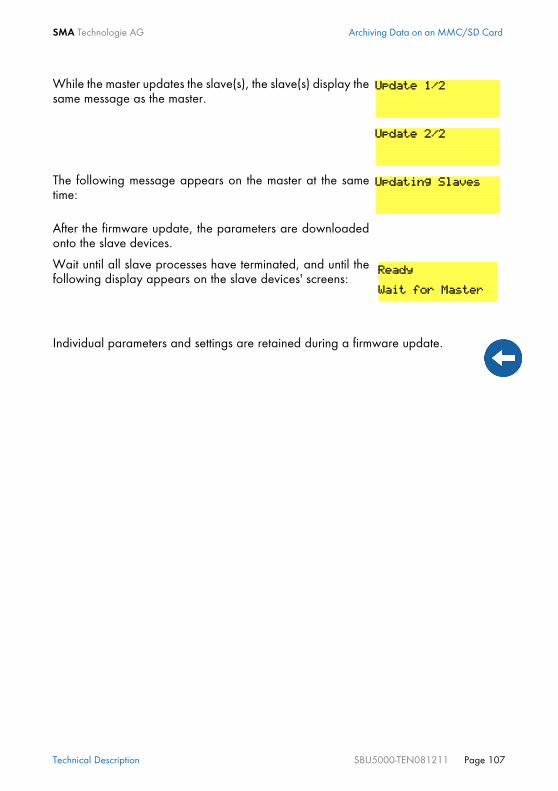
SMA Technologie AG Archiving Data on an MMC/SD Card
Technical Description SBU5000-TEN081211 Page 107
While the master updates the slave(s), the slave(s) display thesame message as the master.
The following message appears on the master at the sametime:
After the firmware update, the parameters are downloadedonto the slave devices.
Wait until all slave processes have terminated, and until thefollowing display appears on the slave devices' screens:
Individual parameters and settings are retained during a firmware update.
Update 1/2
Update 2/2
Updating Slaves
Ready
Wait for Master

Inverter Operation SMA Technologie AG
Page 108 SBU5000-TEN081211 Technical Description
12 Inverter Operation
12.1 Overload and Short-circuit BehaviorThe Sunny Backup 5000 can be temporarily operated under overload conditions. Itcan also supply short-circuit currents.In case of overload, the Sunny Backup 5000 supplies an output of 6500 W for 30minutes and can supply 7200 W for 5 minutes. The device can even supply 8400 Wof output power for one minute.If a short circuit occurs, the Sunny Backup 5000 provides current of max. 100 A (for100 ms). This is sufficient to trigger commercial 16 A B-type circuit breakers.
12.2 Device Faults and AutostartIf a critical fault occurs, the Sunny Backup 5000 automatically shuts down and displaysthe reason on the display. If the autostart function ("250.01 AutoStr" parameter) isactivated, the Sunny Backup 5000 can automatically confirm any errors of category 2or 3 (see section 20.7 "Error Categories" (Page 163)), and can restart on its own. If thefault remains, the Sunny Backup 5000 cannot be started.
If the autostart meter has counted down to 0, the Sunny Backup 5000 waits for10 minutes before trying to automatically restart again.
Messages can be displayed at any time while the device is in operation and theyhave priority over the Home Screen display.

SMA Technologie AG Grid
Technical Description SBU5000-TEN081211 Page 109
13 GridThe Sunny Backup systems are designed as very rapidly switching backup powersupplies for operation on the public grid. Here, a distinction is made between two mainstates: • Public grid present • Grid failure (stand-alone grid operation)The operating mode of the inverter is derived from this. If the public grid is available,the loads in the main power grid are supplied with electricity, and the Sunny Backup5000 charges the batteries, or keeps them fully charged. The PV system feeds into thepublic grid via a dedicated meter. Upon grid failure, the Sunny Backup systemdisconnects the public grid from the loads within no more than 20 ms, and suppliesthese loads with grid-quality voltage. While the grid remains down (stand-alone gridoperation), the inverter is thus solely responsible for powering the loads. The PV systemis then switched to the consumer side, and feeds a current into this stand-alone grid,depending on the solar radiation. If at any time more PV energy is being generatedthan consumed, it is stored temporarily in the battery. If more energy is being consumedthan the PV system is generating, the extra energy required is taken from the battery.
13.1 ConditionsFor operation on the public grid, the voltage and frequency threshold values asstipulated by the applicable local standard (for example in Germany theDIN VDE 0126-1-1 Standard) must be continuously monitored. If these thresholds arebreached, the Sunny Backup system disconnects from the grid within no longer than200 ms (value taken from the DIN VDE 0126-1-1).
During these 200 ms, the loads continue to be powered, as although the gridvoltage or frequency breaches the thresholds, there is still sufficient voltage andfrequency available. If the voltage fails completely, disconnection occurs in max.20 ms.
In certain cases, it may be necessary to adapt the thresholds for voltage andfrequency to the grid situation in order to prevent grid disconnection fromoccurring too frequently. In such instances, it is imperative to consult the energysupply company. To adjust these thresholds in the "232# Grid Control" menu, youmust first enter your individual SMA grid guard password (see section 10.7"Entering the Installer Identification" (Page 98)).

Grid SMA Technologie AG
Page 110 SBU5000-TEN081211 Technical Description
13.2 Operating on the Public GridIn grid operation, the loads and the Sunny Backup 5000 are connected to the publicgrid. In this case, the voltage and frequency in both grids are identical. In gridoperation, grid monitoring checks for breaches of the permissible limits for voltage andfrequency (see Grid Reconnection), and for grid failure. If the thresholds are breached,or in the event of a complete grid failure, the public grid is disconnected, and operationcontinues almost uninterruptedly as a stand-alone grid. The battery is generally chargedor its charge is maintained on the grid.
13.3 Grid FailureA grid fault is characterized by the voltage or frequency being outside of thepermissible limits (see section 13.5 "Grid Reconnection" (Page 110)) or the main powergrid being disconnected. In this case, the time limits are relevant: Smaller deviations arepermitted for longer than large deviations. In case of a grid fault/failure, the public gridis disconnected and the inverter starts, if it is not already running (silent mode).
13.4 Stand-Alone Grid OperationIf the public grid has failed, and the loads are disconnected, the inverter powers thestand-alone grid. The system waiting for the grid to reconnect is an indication of thisstate. As long as the battery has a sufficient charge level, the loads are powered. Instand-alone operation, charging may occur via the PV system, or other connectedenergy sources (CHP plants, wind energy systems, etc.).
13.5 Grid ReconnectionIn stand-alone operation, the inverter constantly checks whether the grid has beenreconnected (see above). If the voltage and frequency of the main power grid arewithin the permissible range of the "232.01 GdVtgMin" and "232.02 GdVtgMax"parameters for the "232.07 GdVldTm" time and the frequency is within the permissiblerange of the "232.05 GdFrqMin" and "232.06 GdFrqMax" parameters (see section13.1 "Conditions" (Page 109)), the stand-alone grid is synchronized with the mainpower grid and then connected.If the battery is fully charged, the frequency limits the power output of the AC feed-ingenerators (Sunny Boys) in the stand-alone grid. If the grid is now reconnected, thefrequency would be lowered, if required, as the Sunny Backup 5000 is synchronizedwith the grid. The AC feed-in generators (Sunny Boys) would then feed additionalenergy into the system and possibly overload the batteries. In order to prevent thisduring such conditions, the stand-alone grid frequency is temporarily increased
If grid failure occurs while the Sunny Backup 5000 is in silent mode, this maycause a longer interruption period than that described in section 13.1"Conditions" (Page 109).

SMA Technologie AG Grid
Technical Description SBU5000-TEN081211 Page 111
("231.04 AcSrcFrqDel" parameter), in line with the synchronization, until the AC feed-in generators (Sunny Boys) are disconnected from the stand-alone grid as a result of thegrid limits being exceeded.
13.6 Limits and Power AdjustmentThe Sunny Backup 5000 charges the public grid during each phase using the currentspecified via the "232.03 GdCurNom" parameter. The power that is not directly usedby the loads flows into the battery for charging. The limits for the AC charging currentlimit ("210.02 InvChrgCurMax" parameter) on the Sunny Backup 5000 and the DCcharging current limit ("222.01 BatChrgCurMax" parameter) are active at the sametime. If the battery voltage reaches the charging voltage nominal value, it is alsoreduced (see section 14.4 "Charge Control" (Page 117)). If the current set using the"232.03 GdCurNom" parameter is not sufficient for powering the loads, the batteryprovides support.
The thresholds are cutoff limits; due to internal hysteresis, the reconnection limitsare set somewhat more narrowly.

Grid SMA Technologie AG
Page 112 SBU5000-TEN081211 Technical Description
13.7 Grid feeding from the battery
The backup system can feed electricity from the battery into the public grid. This electri-city is independent of the electricity from the PV system. The backup system measuresthe electricity fed on the grid side upstream of the grid/stand-alone grid contactor insidethe Automatic Switch Box.
If the battery state of charge falls below a specific state of charge, the backup systemdiscontinues the grid feeding (“232.43 FedInSocStp” parameter). If the battery state ofcharge increases again, the grid feeding is continued (parameter “232.42FedInSocStr”).
Before using the battery grid feed feature, please contact your energy supplier inorder to verify the local standards.
This feature can only be used with the SBU-SET-M and SBU-SET-L.
If, due to the low battery state of charge, the grid feeding is interrupted, the gridfeeding period is ended as specified in the parameter settings. The battery is onlycharged by the grid after the set time has expired. This ensures that the public gridis not additionally compromised.
0 0 7 8 5 5 6kWh
ENTERENTER
ESCESC
Sunny Backup 5000
Sunny Backup 5000
GeneratorGeneratorcontactor
Grid/Stand-alone gridcontactor
0 0 7 8 5 5 6kWh
PV couplingcontactor
Automatic disconnectiondevice for PV systems
Switching device
Sunny Backup system
SunnyBackup5000
Battery
Referencecounter
PV feed-in counter
BetriebOperation
ErdschlussEarth FaultStörungFailure
Public grid
Loads
PV system
Measuring point of the electricity fed into the grid from the battery

SMA Technologie AG Grid
Technical Description SBU5000-TEN081211 Page 113
If energy-intensive loads are operated during the grid feeding, the inverter reduces theelectricity to be fed. The respective nominal value for active current (parameter“232.46 FedInCurAt”) or reactive current (parameter “232.47 FedInCurRt”) is lowereduntil the nominal current does not exceed the value of 21.7 A.Different grid feeding methods can be selected using the “232.41 FedInMod”parameter. A time-dependent or signal-controlled feeding can be selected.
13.7.1 Time-dependent grid feedingIf the “232.41 FedInMod” parameter is set to “Time”, the electricity from the battery isfed into the public grid for a specified time period. The start time for the time-dependentgrid feeding is set using the “232.44 FedInTmStr” parameter. The process is stoppedusing the “232.45 FedInTmStp” parameter setting. The active current to be fed into thegrid is set using the “232.46 FedInCurAt” parameter and the reactive current is set usingthe “232.47 FedInCurRt” parameter.
13.7.2 Signal-controlled grid feedingIn this case, the grid feeding is activated by a external dry contact. For example by aripple control signal which is sent from the energy supplier that has activated or endedthe grid feeding. To allow this, set the "232.41 FedInMod" parameter to “Signal”. Theactive current to be fed into the grid is set using the “232.46 FedInCurAt” parameterand the reactive current is set using the “232.47 FedInCurRt” parameter. Once the drycontact is closed, the Sunny Backup 5000 starts feeding the electricity into the publicgrid.Connect the dry contact to the terminal strip „X7/Feed In Signal“ in the AutomaticSwitch Box.

Grid SMA Technologie AG
Page 114 SBU5000-TEN081211 Technical Description

SMA Technologie AG Battery Management
Technical Description SBU5000-TEN081211 Page 115
14 Battery ManagementThe battery management of the Sunny Backup 5000 supports the following threebattery types ("221.01 BatTyp" parameter):FLA Flooded Lead Acid: closed lead acid batteries with liquid electrolyte in all
standard designs available on the market (grid plate, tubular plate, small,large, etc.)
VRLA Valve Regulated Lead Acid: closed lead acid batteries with immobilizedelectrolyte in gel or AGM (Absorbent Glass Mat Separator) in all standarddesigns available on the market (grid plate, tubular plate, small, large, AGM,Gel, etc.)
NiCd Nickel Cadmium: pocket-type plate or fiber plate closed nickel cadmiumbatteries
The battery capacity ("221.02 NomBatCpy" parameter) is to be entered as the nominalcapacity for a ten hour discharge (C10). If this is not available from the batterymanufacturer's data sheet, it can be calculated from the data for different dischargetimes (120 h, 100 h, 20 h, 5 h, 1 h) in the following manner:
The Sunny Backup 5000 is designed and preset for a nominal battery voltage("221.03 BatVtgNom" parameter) of 48 V (24 cells for every 2 V) with lead acidbatteries (FLA and VRLA) and 45.6 V (38 cells for every 1.2 V) with nickel cadmiumbatteries.
14.1 Battery TemperatureThe Sunny Backup 5000 continuously monitors the battery temperature using theprovided battery temperature sensor. A warning message is displayed once the batterytemperature drops 5 °C below the maximum permissible temperature ("221.04BatTmpMax" parameter).When lead acid batteries drop –10 °C below the set limit and NiCd batteries drop –20 °C below the set limit, a warning is displayed.The battery temperature is taken into consideration when the charging voltage iscalculated (see section 14.4 "Charge Control" (Page 117)).
C10 C120/1.28 C10 C10
C10 C100/1.25 C10 C5/0.88
C10 C20/1.09 C10 C1/0.61
If individual battery cells fail over several years of continuous operation, thenominal voltage can be set in the range from 42 V to 48 V. Up to three individualcells can be removed and the system can still be further operated.This is not possible with 12 V blocks!

Battery Management SMA Technologie AG
Page 116 SBU5000-TEN081211 Technical Description
14.2 Start OptionsIf the battery or individual cells are removed from the battery bank in a system, thebattery management must be restarted and configured. This can be done using the"Quick Configuration Guide QCG" (see section 8.2 "Starting the Quick ConfigurationGuide (QCG)" (Page 77)).
14.3 State of Charge/SOC and SOHThe Sunny Backup 5000 has a very precise internal charge level calculation (displayvalue "120.01 BatSoc"). The operation for calculating the charge level is based onbalancing the ampere hours. That means that all currents that flow in and out of thebattery are added together and based on the nominal capacity. In order to take intoconsideration faults caused by self discharge and charging losses caused by gassing,these losses are already internally omitted. Unlike other operations, no fixed chargingfactor must be set.When the fully charged state is reached, the charge state value is set back to 90 %,95 % or 100 %, depending on how full the battery was actually charged. If the defaultsettings are not changed, a charge state of 90 % is normally reached after a boostcharge; a charge state of 95 % is normally reached after a full charge, and a chargestate of 100 % is normally reached after an equalization charge. Since fully charged states are only rarely achieved during a grid failure, the operationused here can also utilize the battery voltage during constant discharge phases with lowdischarge currents to recalibrate the charge state. These phases are generally reachedat night. Compared to the ampere hour balancing method, the operation used hereexhibits a high level of stability over the long term when recalibrated at regularintervals. Both the ampere hour balancing method and the recalibration procedure, which isperformed via the voltage, automatically adjust to the connected battery over time(depends on the number of grid failures). Since many of the battery types on the markettoday exhibit extremely varied behavior, no values can be determined. The best optionis to make adjustments to the respective battery according to the procedures describedabove.The estimated charge state error (display value "120.11 BatSocErr") will provide youwith continuous information on the accuracy of the battery charge state currentlycalculated. The average error will continuously diminish as the adjustment to the actualbattery increasingly improves.
If the battery temperature sensor is not connected or a short circuit or a cablebreak on the sensor is detected, a warning message is generated; however, theSunny Backup 5000 continues to operate at a fixed set battery temperature of40 °C. Over time this leads to insufficient battery charging.

SMA Technologie AG Battery Management
Technical Description SBU5000-TEN081211 Page 117
Only when the battery is new does its usable capacity correspond to the capacityspecified by the battery manufacturer. As the battery ages and as a result of frequentinsufficient charging, the battery’s useable capacity may decrease considerably on apermanent or only a temporary basis. The battery's state of health (display value"342.01 Soh") is a percentage measurement for the present useable capacity relativeto the nominal capacity. 100 % means that the entire nominal capacity can still beutilized. At 50 %, only half of the original nominal battery capacity can be utilized. Thebattery's state of health is also calculated by means of a self-adapting method whichhowever can only produce good and exact values after a number of grid failures, orafter regular grid failures. The present capacity for the Sunny Backup 5000 is automatically adjusted downwardsfor temperatures <20 °C, since the useful capacity of batteries is significantly reducedin temperatures below the nominal temperature. For all lead acid batteries, the nominalcapacity is amended by a fixed factor of –1 %/°C. For NiCd batteries a factor of –0.75 %/°C is used.
14.4 Charge ControlThe Sunny Backup 5000 performs charge control in 3 phases, using the IUoU process.When the device operates with the public grid, there is also an optional fourth phasecalled silent mode.
The I stands for the constant voltage phase (I phase). In this phase, the charging islimited by the maximum defined battery current ("222.01 BatChrgCurMax"parameter), the nominal generator current ("242.03 GnCurNom" parameter), thenominal grid current ("232.03 GdCurNom" parameter) or the maximum AC charging
AptTmBoost = 120 min
Sp
annung
/V
olt
ag
e[V
]Str
om
/Curr
ent
[A]
Zeit / Time
ChrgVtgBoost = 2.4 V
AptTmFul = 5h
AptTmEqu = 10 h
I-Phase /Bulk Phase
Uo-Phase /Absorption Phase
U-Phase /Float Phase
ChrgVtgFul = 2.4 V
ChrgVtgEqu = 2.4 V
Ruhephase/Silent Mode(nur beim Netzbetrieb /only with public grid)
U-Phase /Float Phase
SilentTmMax = 12 h
ChrgVtgFlo = 2.25 VSilentTmFlo = 3 h

Battery Management SMA Technologie AG
Page 118 SBU5000-TEN081211 Technical Description
current of the Sunny Backup 5000 ("210.02 InvChrgCurMax" parameter). Therespective value reached first is the limiting value. During this phase the battery voltageincreases as the battery is charged. Once the battery voltage reaches the predefined value for the second phase Uo("222.07 — 222.09", ChrgVtgBoost or ChrgVtgFul or ChrgVtgEqu parameters), theconstant voltage charging (absorption phase) begins. In this phase, the battery voltageis maintained at a constant level, resulting in a continually decreasing battery current.The Sunny Backup 5000 remains in this phase for the defined period of time ("222.01— 222.03", AptTmBoost or AptTmFul or AptTmEqu" parameters). For this chargingphase, the Sunny Backup 5000 automatically selects one of the three possible chargingprocesses (boost, full, equalizing) that are described in more depth between sections14.4.1 and 14.4.3. The remaining charging time (display value "120.04 AptTmRmg")of this phase and the current process (display value "120.05 BatChrgOp") can be readon the display. The following figure displays the relationship and the process diagram of the chargingphases and charging processes.
Once this constant voltage phase is finished, the Sunny Backup 5000 switches to floatcharge which again carries out constant voltage charging but at a greatly reducedcharging voltage ("222.10 ChrgVtgFlo" parameter). The purpose of the float charge is
Equalization Charge(U Phase)0
Full Charge(U Phase)0
Boost Charge(U Phase)0
I-Phase
Float Charge(U Phase)
Silent Mode
Charging process
Cha
rgin
g p
ha
ses
Manual
5
1
4
6 7
4 4
3 2
2
Legend:1: After reaching threshold2: After time CycTmEqu (#225.05)3: After time CycTmFul (#225.04)4: If AptTmRmg = 0 (#120.04)5: If SOC < 70 % (#120.01)6: Only on grid if SilentTmFlo has elapsed (#224.02)7: Only on grid if SilentTmMax has elapsed (#224.03)

SMA Technologie AG Battery Management
Technical Description SBU5000-TEN081211 Page 119
to keep the battery in a fully charged state without causing premature aging throughovercharging. The Sunny Backup 5000 remains in this phase until either more than30 % of the nominal capacity (all discharges are added together) has been used or thecharge state is less than 70 %. When the Sunny Backup 5000 is operating on the publicgrid, it can also switch from the float charge into silent mode.
The charging capability of batteries is heavily dependent on the battery temperature.For temperatures <20 °C, the charging voltage must be slightly increased, and fortemperatures >20 °C it must be slightly decreased. This is necessary to preventovercharging and insufficient charging reliably at any battery temperature. For thisreason, the Sunny Backup 5000 is equipped with automatic temperature compensationof the charging voltage. The charging voltage is adjusted by 4 mV/°C and cell forbattery types VLA and FRLA as well as by 0 mV/°C and cell with NiCd batteries. Thetemperature compensation value can be set using the "222.11 BatTmpCps" parameter.
14.4.1 Boost ChargeThe boost charge enables the battery to be charged to approximately 85 % to 90 %by means of a high charging voltage for a short period.
14.4.2 Full ChargeAfter a discharge of more than 30 %, the Sunny Backup 5000 automatically initiates afull charge if more than 14 days (parameter "222.05 CycTmFul“) have passed sincethe previous grid failure. The objective is to recharge the battery to a charge level of atleast 95 %.
The charging voltage does not rapidly change, but is slowly adjusted to the newnominal value by approx. 0.5 mV/cell*s as the constant voltage phase changesto the float charge. This also takes place if the nominal value is changedmanually.
If a Sunny Backup system is newly installed, the Sunny Backup 5000 first performsa full charge, then switches to float charge. Thus, the battery is always kept at ahigh charge level of 95 % to 100 %. Only after a grid failure during which thebattery is discharged by more than 30 % is the battery recharged with one of theother charging processes (boost charge, full charge, or equalization charge).
Boost charges are primarily relevant if grid failures occur in relatively quicksuccession in order to then effectively recharge the battery as quickly as possibleduring the periods when the grid is available.

Battery Management SMA Technologie AG
Page 120 SBU5000-TEN081211 Technical Description
14.4.3 Equalization ChargeAfter a discharge of more than 30 %, the Sunny Backup 5000 automatically initiatesan equalization charge if more than 180 days (parameter "222.06 CycTmEqu") havepassed since the previous grid failure. The objective is to recharge the battery to acharge level of at least 95 % to 100 %.During this process, the Sunny Backup 5000 performs controlled overcharging of thebattery bank to ensure that even the weaker cells are fully recharged. The equalizationcharge is simultaneously a type of battery maintenance, and extends the battery servicelife.
14.4.4 Silent ModeOnly during operation on the public grid, and at times when PV grid feeding is notpossible, can the silent mode be used alongside the float charge. Silent mode causesthe system's operating consumption to decrease significantly. Silent mode is activated by means of the "224.01 SilentEna" parameter. Theparameters "231.01 PvFeedTmStr" and "231.02 PvFeedTmStp" stipulate the timesbetween which the PV system can feed; i.e. silent mode is possible in the remaining timewindow (PvFeedTmStp -> PvFeedTmStr).
The Sunny Backup system remains in silent mode for a fixed time ("224.03SilentTmMax" parameter) or until the battery voltage per cell is 0.14 V lower than theset voltage ("222.10 ChrgVtgFlo" parameter). This ensures that the battery is alwaysfully charged, even in silent mode.If a grid failure is detected while in silent mode, the Sunny Backup 5000 restores powersupply within approximately 30 ms. Thus, the interruption period is only slightly longerthan during grid-parallel operation with float charge.
14.4.5 Manual Equalization ChargeAn equalization charge can be manually triggered for the Sunny Backup 5000 at anytime using the "520.01 ManChrgSel" parameter. The equalization charge is activatedonce the manual equalization charge has been confirmed. If the generator is connectedto the system, it is automatically started and stopped again once the equalizationcharge has been completed.
During this period, the PV system is disconnected from the public grid, and cannotfeed. Ensure that the only period stipulated here is one in which the PV system isalso unable to generate energy (night).
An equalization charge should be performed at least once a year. Following along period of time without charging, for example, with systems that are onlyoperated seasonally, a manual equalization charge must always be performedat the end or beginning of the season.

SMA Technologie AG Battery Management
Technical Description SBU5000-TEN081211 Page 121
14.5 Battery Preservation ModeThe Sunny Backup 5000 has a sophisticated battery preservation mode. The batterypreservation mode prevents the battery from being deeply discharged, as much aspossible, when the energy supply is low and thus prevents a total system failure as wellas damage to the battery.
The battery preservation mode has three levels that are activated as a result of the stateof charge (when the charge drops below the respective limit, "223.05 BatPro1Soc","223.06 BatPro2Soc" and "223.07 BatPro3Soc" parameter): Level 1: The first level is used to switch the inverter into standby mode in times duringwhich the energy is not absolutely necessary (e.g. at night). You define the start timeusing the "223.01 BatPro1TmStr" parameter and define the stop time using the"223.02 BatPro1TmStp" parameter.
Level 2: The second level of the battery preservation mode ensures that the inverterregularly starts every two hours, but only during the window of time in which an energysupply is expected, and attempts to charge the battery from the AC side. Forphotovoltaic systems, this occurs during the day. In this case, you define the start timeusing the "223.03 BatPro2TmStr" parameter and the stop time using the"223.04 BatPro2TmStp" parameter.
If a grid failure occurs, and significantly less energy is being generated by the PVsystem than is required, the battery will continue to discharge over time until it isvirtually empty.

Battery Management SMA Technologie AG
Page 122 SBU5000-TEN081211 Technical Description
Level 3: The third level ensures that the battery is protected from deep discharge andthus protected against damage. In this case, the inverter is switched off completely. Tostart the inverter, see section 9.5 "Reactivating the Device Following AutomaticShutdown" (Page 84).During all three levels, the inverter is only stopped if no battery current flows within 5minutes (limit 3 A charging current).The limits for all three levels can be set independently of one another. This allowsindividual levels to be skipped.
For level 1 and 2, a hysteresis of 5 % of the SOC charge level is designated for exitingthis state.
The battery preservation mode on the Sunny Backup 5000 can be exited by manuallystarting the device. If, within 5 minutes (see above), charging current is detected, theSunny Backup 5000 continues to operate; otherwise, it switches off again.
14.6 Battery DiagnosticsIn the menu "320# Battery Diagnosis", many values are displayed that provideinformation on the past operational behavior of the battery. These values are helpful inchecking the efficiency of the set parameters and in viewing the typical operatingconditions of the battery (see section 19.3 "Diagnostics" (Page 154)).
If the BatPro1Soc parameter < BatPro2Soc, level 1 is skipped and only level 2 isperformed.
Battery preservation mode is not automatically exited if an externalvoltage source (grid reconnection) is present.

SMA Technologie AG Connecting a Generator
Technical Description SBU5000-TEN081211 Page 123
15 Connecting a GeneratorSunny Backup systems support the integration of a generator (order option, cannot beretrofitted).
15.1 Generator StartDepending on the battery charge state or the consumer power, the Sunny Backup 5000can start a generator and of course stop it again as well. In this case, diverse limits andtimes are taken into consideration.The Sunny Backup 5000 supports the following options for the generator start that canbe adjusted using the "233.07 GnStrMod" parameter in standby mode:• Manual• Autostart• GenMan
Manual (Manual Generator Start)This setting is for generators that do not have an electrical remote starting option and,for example, are started using cable winches or cranks, among other things.In this case, the Sunny Backup 5000 does not have the option of starting the generator.It only monitors the generator input. If, while monitoring the input, the device detectsthat the generator voltage and frequency are within the set limits (see 15.3 "Limits andPower Adjustment" (Page 128)), the device is synchronized and switches on followingthe warm up time. The generator is also always switched off manually. The Sunny Backup 5000 thenautomatically switches into the operating mode without the generator.
With Sunny Backup systems, the generator cannot be operated at the same timeas the public grid, but rather instead of the public grid.Thus, operation with combined heat and power (CHP) plants is not possible.
The GnReq signal (see 16 "Relay" (Page 133)) is set for signaling the generatorrequest and can thus be used as an alarm contact. If no request is pending, thesignal is disabled again.If an internal request is sent while the generator is already running, the signal isdisabled until the generator is externally stopped and the stop time has expired.
A disconnector should be located between the Sunny Backup 5000 and thegenerator. If the generator is to be stopped, it is first manually disconnected usingthe disconnector and then it is stopped. This prevents powering the generatorwhile switching it off.

Connecting a Generator SMA Technologie AG
Page 124 SBU5000-TEN081211 Technical Description
AutostartThis allows remote control generators to be directly integrated. They have a separateinternal controller that controls the start procedure.The Sunny Backup 5000 requests the generator using the GnReq signal. If thegenerator voltage and frequency are within the set limits (see 15.3 "Limits and PowerAdjustment" (Page 128)), the device is synchronized and switched on following thewarm up time.The Sunny Backup 5000 keeps the request signal stable until a disconnection is madeand the set power down time has expired.
If you directly start the generator manually in this operating mode, the Sunny Backup5000 detects the running generator and connects it once the warm up time has expired.If you stop the generator externally, this is detected and the generator is disconnectedand the stand-alone grid continues to be powered.
GenManIf a GenMan (generator manager) (SMA order number: "SI-GenMan-...") is integratedinto the system, it assumes direct control of the generator. It is connected between theSunny Backup 5000 and the generator. The GenMan assumes control of the generator(warm up time, cooling off time and autostart).
This integration of the generator requires permanent installation of thegenerator connection. Otherwise, if the generator connection at a plugsocket is pulled out during operation, reverse voltage may arise at theplug for up to five seconds.
Remote control generators can also have an internal power down cycle that isonly activated when the request has been disabled. This can extend the powerdown time accordingly.
With some generator types, the voltage is only switched to the output after theinternal warm up phase is finished. Therefore the time of the generator activationsequence is monitored internally:Time to activation = 10 minutes for GenMan or 2 x "233.12 GnWarmTm" + 2minutes for manual and autostart.
If the generator is running after being externally started and a generator requestoccurs, the GnReq signal is disabled until the generator is externally stoppedagain and the stop time has expired.

SMA Technologie AG Connecting a Generator
Technical Description SBU5000-TEN081211 Page 125
Using the GnReq signal, the Sunny Backup 5000 requests the generator at theGenMan and keeps this signal stable until the request is successful. The GenManreturns the GENRDY signal via DigIn (see 6.6 "GenMan Connection" (Page 62)) if thegenerator is ready for operation. Afterwards, the Sunny Backup 5000 can synchronizeand connect. If the generator is no longer required, the Sunny Backup 5000disconnects itself and disables the GnReq signal.
The GENRDY signal sends a manual generator start at the GenMan to the SunnyBackup 5000. The device synchronizes and connects.If the generator is externally and manually started at the GenMan, Sunny Backup 5000blocks the GnReq signal:• Manual stop and start are ignored on the Sunny Backup 5000 (operated using
the display and keyboard).• Internal requests (e.g. via the battery charge state) are also ignored.
The Sunny Backup 5000 disconnects the generator if the GenMan has disabled theGENRDY signal.
15.2 Generator OperationThe Sunny Backup 5000 allows automatic operation (depending on charge state orload) (see 15.2.2 "Automatic Generator Operation" (Page 126)). In addition, manualoperation is also possible.
15.2.1 Manual Generator OperationThe manual operating modes for the generator management are triggered using the"540.01 GnManStr" parameter. Here a distinction is made between the followingoperating modes:Auto: In this operating mode, the generator is automatically started due to the
settings. This includes the start as a result of the charge state or theconsumer power or by a request for a manual equalization charge("520.01 ManChrgSel" = Start).
If the generator has been manually started at the GenMan, it must also bestopped there.
A manual start directly at the generator is not permitted (see GenMan manual).

Connecting a Generator SMA Technologie AG
Page 126 SBU5000-TEN081211 Technical Description
Stop: Manual generator stop if it is manually started. Cancels the presentgenerator request – immediately disconnects from the generator andtransitions into the lockout state. Once the lockout time has ended, thegenerator switches into automatic operation.
Start: Manual generator start – generator runs "continuously" until stopRun1h: Operation for one hour. Once the lockout time has expired, the transition
back into automatic mode follows.
15.2.2 Automatic Generator OperationIn automatic operating mode ("234.01 GnAutoEna" parameter), the Sunny Backup5000 automatically defines the settings (depending on battery charge state or load) asto when the generator starts and how long it runs. The automatic operating mode isactivated using GnAutoEna = On (default). If GnAutoEna = Off, the automaticoperating mode is deactivated.In addition, the user can also manually start and stop the generator, if required.
Charge State Dependent Start
The time periods t1 and t2 are defined using the "234.07 GnTm1Str" and "234.08GnTm2Str" parameters. The start time for t1 (and thus the end of t2) is defined usingGnTm1Str, and the start time for t2 (end of t1) is defined using GnTm2Str.
The time intervals t1 and t2 are assigned charge states for start-up and stop using the"234.03 GnSocTm1Srt", "234.04 GnSocTm1Stp", "234.05 GnSocTm2Strt" and"234.06 GnSocTm2Stp" parameters. GnSocTm1Strt designates the battery charge
If the generator has been manually started (start), it must be manuallystopped (stop).
Manual specifications on the Sunny Backup 5000 take priority over theautomatic operating mode. If the Sunny Backup 5000 is manually stoppedwhile the automatic operating mode is activated, the Sunny Backup 5000enters into stop/lock operating mode.If the generator autostart is activated and all the conditions for automaticoperation are satisfied, the Sunny Backup 5000 switches back into thestart operating mode following the lockout time (or manual confirmationusing the "540.02 GnAck" parameter).
If GnTm1Str = GnTm2Str, only settings for t1 are active!

SMA Technologie AG Connecting a Generator
Technical Description SBU5000-TEN081211 Page 127
state at which the generator is started during the t1 time and GnSocTm1Stp designatesthe charge state at which the generator is switched off during t1. The GnSocTm2Str andGnSocTm2Stp parameters are similarly defined during the time t2.
Load Dependent StartIn case increased energy demands arise, the generator can be requested for support.This function can be switched on or off (default) using the "234.09 GnPwrEna"parameter. The function is only effective if the "234.01 GnAutoEna" parameter issimultaneously set to On.The load limit for the request and the generator stop is configured using the "234.10GnPwrStr" and "234.11 GnPwrStp" parameters. The average time by which anaverage value for the consumer power is calculated can be set using "234.12GnPwrAvgTm". This prevents temporary power consumption peaks that last for severalseconds from causing a load dependent generator start.
The figure displays an example of the settings if operation of the generator atnight is to be avoided as much as possible. Between 6 a.m. and 10 p.m., thegenerator is started at a charge state (SOC) of 40 % and by contrast, the batteryis discharged to 30 % at night (between 10 p.m. and 6 a.m.) before the dieselgenerator starts.
If the float charging process (see section 14.4 "Charge Control" (Page 117)) isactivated before the cutoff limit (GnSocTm1Stp or GnSocTm2Stp) is reached, thegenerator request is disabled again. If a full or equalization charge is active, thegenerator is only stopped after this charge is completed and not when "234.04GnSocTm1Stp" or "234.06 GnSocTm2Stp" is reached.
GnSoc Tm2 Stp GnSoc Tm2 Stp
0h 6h
GnTm1Str GnTm2Str
GenSoc Tm1 Stp
18h 24h
GnSoc TM2 Str GnSoc Tm2 Str
GenSoc Tm1 Str
t1
t2t230
40
80
Soc [%]

Connecting a Generator SMA Technologie AG
Page 128 SBU5000-TEN081211 Technical Description
If the generator has been started due to the load, it runs according to the minimumgenerator run time. If, once this time has expired, the average power is below the cutofflimit, the generator is stopped again.
15.3 Limits and Power AdjustmentThe voltage limits can be set using the "233.01 GnVtgMin" and "233.01 GnVtgMax"parameters and the frequency limits for generator operation can be set using the"233.05 GnFrqMin" and "233.06 GnFrqMax" parameters. If the values are outsidethese permitted limits, the generator is disconnected. Slightly restricted limits are appliedto generator connection.The voltage and frequency limits are monitored in phases. All phases on the masterdevice must meet the defined limits to connect the generator.The Sunny Backup 5000 charges the generator during each phase using the currentspecified in the "233.03 GnCurNom" parameter. The power that is not directly used bythe loads flows into the battery for charging. The limits for the AC charging current limit("210.02 InvChrgCurMax" parameter) on the Sunny Backup 5000 and the DCcharging current limit ("222.01 BatChrgCurMax" parameter) are active at the sametime. Low values for this limit may be the reason why the defined generator currentcannot be adjusted. If the battery voltage reaches the charging voltage nominal value,it is also reduced (absorption phase, see section 14.4 "Charge Control" (Page 117)).
If the "233.15 GnCtlMod" parameter is set to CurFrq, the generator is also limited atfrequencies lower than the nominal frequency ("242.04 GnFrqNom" parameter). Thisfunction can be used if the full generator output is not always available and you wantto prevent the generator from being overloaded. The default setting is only intended tocontrol the nominal generator current.If the current set using the "233.03 GnCurNom" parameter is not sufficient for poweringthe loads, the battery provides support ("real generator support").
Only the total consumer power of all phases is monitored. Individual phases in amulti-phase system are not monitored.The consumer power is determined from the inverter power("111.01 TotInvPwrAt") and generator power ("131.01 TotExtPwrAt").
Warm up times, minimum run times and power down times are also maintainedfor load dependent generator starts.
A sensible value for the "233.03 GnCurNom" parameter is approximately 80 %of the maximum generator current for each phase.

SMA Technologie AG Connecting a Generator
Technical Description SBU5000-TEN081211 Page 129
15.4 Run TimesIf the generator is started (or the Sunny Backup 5000 detects an external generatorstart), the warm up phase starts. If, during this time, the voltage or frequency detectedis not within the permissible range, the warm up time begins again. If the generatorcannot be connected at the GenMan within twice the time of "233.12 GnWarmTm" +2 or 10 minutes, the connection process is cancelled and a new attempt is made. Afterthree attempts, the system goes into error state (Fail). Once the 5-minute error wait timehas expired, a new attempt is made. If the generator has been connected, the minimum run time begins ("233.08GnOpTmMin" parameter). The generator remains connected during this time, even if inthe meantime the generator request is no longer pending. If the minimum run time has expired and a request is no longer pending or the systemdetects that the set limits have not been maintained, the generator disconnects andtransitions into the power down phase (Cool). If this power down phase is completedafter the "233.10 GnCoolTm" time, the generator is stopped.
If a generator fault (e.g. generator failure) is detected, the generator is alsodisconnected and then stopped immediately. In doing so, the power down time isskipped.Once the stop time ("233.09 GnStpTmMin" parameter) has expired, the generator isready for the next request.
If a generator fault is detected several times and the number of autostarts ("234.02GnAutoStr" parameter) has been exceeded, the system transitions into the locked errorstate. This state lasts for the "233.11 GnErrStpTm" time. Once this time has expired, thegenerator is ready for another attempt.
The power down time ("233.10 GnCoolTm" parameter) defined on the SunnyBackup 5000 should be set equal to or preferably greater than the power downtime of the GenMan.
An internal generator request is disabled during the power down time and stoptime or in error state.
The recording of autostarts is only reset after the generator has been successfullyconnected and the minimum run time has expired or when the locked error state(FailLock) is disabled.
The error state as well as the locked error state can be cancelled by confirmingthe generator fault ("540.02 GnAck" parameter).

Connecting a Generator SMA Technologie AG
Page 130 SBU5000-TEN081211 Technical Description
The "133.03 GnRmgTm" process value is used to display the remaining time of thegenerator meter. Depending on the current request or the phase in which the generatorstate machine is, the following times are displayed:• Remaining time of Run1h • Remaining run time during the warm up time (Warm)• Remaining minimum run time in operation (Run)• Remaining run time during the power down time (Cool)• Remaining stop time after the power down time has expired (Lock)• Remaining time in the error state (Fail)• Remaining time in the locked error state (FailLock)
15.5 Operation Together With Sunny BoysIf the battery is fully charged, the frequency limits the power output of the AC feed-ingenerators (Sunny Boys). If the generator is now manually started, for example, thefrequency would be lowered, if required, as the Sunny Backup 5000 synchronizes withthe generator. The AC feed-in generators (Sunny Boys) would then feed additionalenergy into the system and possibly overload the batteries. In order to prevent thisduring such conditions, the stand-alone grid frequency is temporarily increased("231.04 AcSrcFrqDel" parameter), in line with the synchronization, until the AC feed-in generators (Sunny Boys) are disconnected from the stand-alone grid as a result of thegrid limits being exceeded.
15.6 Stopping the GeneratorIf the Sunny Backup 5000 (automatically or manually) has started the generator, it canbe manually stopped at any time using the "540.01 GnManStr" parameter. Thisdisconnects the generator (the minimum run time is not taken into account here) and thepower down time (Cool) is skipped. Afterwards, the system transitions into the stop time(Lock).
If the generator start is performed directly at the GenMan or thegenerator, it can only be stopped there again. Triggering a stop here onlydisconnects the generator and the system transitions into the stop time(Lock).
Generators with the manual start option can generally only be started andstopped at the generator.
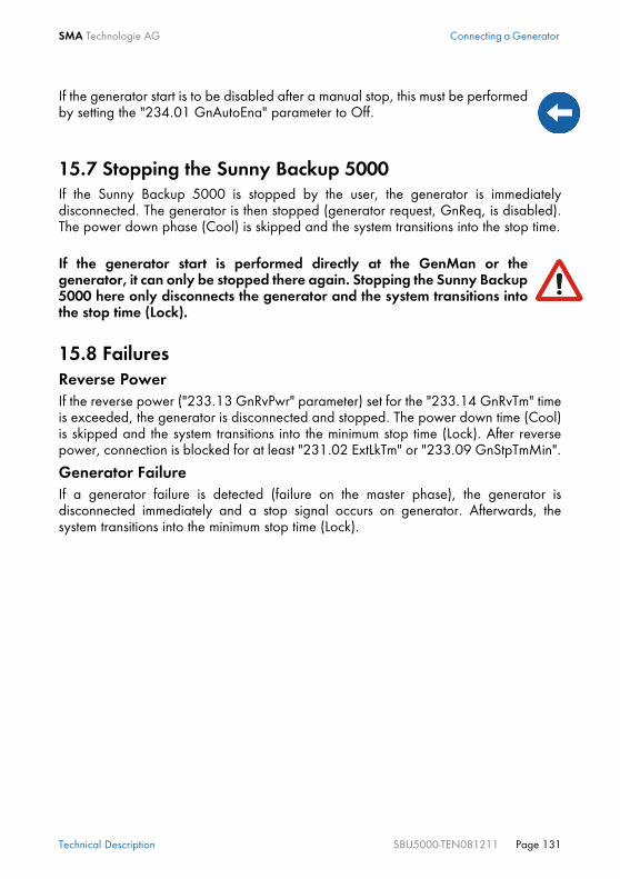
SMA Technologie AG Connecting a Generator
Technical Description SBU5000-TEN081211 Page 131
15.7 Stopping the Sunny Backup 5000If the Sunny Backup 5000 is stopped by the user, the generator is immediatelydisconnected. The generator is then stopped (generator request, GnReq, is disabled).The power down phase (Cool) is skipped and the system transitions into the stop time.
15.8 FailuresReverse PowerIf the reverse power ("233.13 GnRvPwr" parameter) set for the "233.14 GnRvTm" timeis exceeded, the generator is disconnected and stopped. The power down time (Cool)is skipped and the system transitions into the minimum stop time (Lock). After reversepower, connection is blocked for at least "231.02 ExtLkTm" or "233.09 GnStpTmMin".
Generator FailureIf a generator failure is detected (failure on the master phase), the generator isdisconnected immediately and a stop signal occurs on generator. Afterwards, thesystem transitions into the minimum stop time (Lock).
If the generator start is to be disabled after a manual stop, this must be performedby setting the "234.01 GnAutoEna" parameter to Off.
If the generator start is performed directly at the GenMan or thegenerator, it can only be stopped there again. Stopping the Sunny Backup5000 here only disconnects the generator and the system transitions intothe stop time (Lock).

Connecting a Generator SMA Technologie AG
Page 132 SBU5000-TEN081211 Technical Description

SMA Technologie AG Relay
Technical Description SBU5000-TEN081211 Page 133
16 RelayThe Sunny Backup 5000 provides you with many options to control internal andexternal operations. For this purpose, two relays are integrated into the device withwhich you can assign functions using the "261.01 Rly1Op" and "261.02 Rly2Op"parameters. Information on the connection of both relays is provided in section 6.4.4"Multi-function Relay 1 and 2" (Page 53). The different settings have the followingmeanings:
Function/Settings
Meaning Functional description
Off relay remains permanently switched off (deactivated)
On relay remains permanently switched on (e.g. relay function test during commissioning)
AutoGn automatic generator request the generator is automatically activated due to set criteria (see section 15.2.2 "Automatic Generator Operation" (Page 126)).
AutoLodExt automatic load shedding dependent on an external source
automatic connection / disconnection of loadsconnection only occurs if the device is connected to an external source (e.g. generator), or if the absorption phase is active
AutoLodSoc1 Auto LoadShedding Soc1 automatic connection / disconnection of loadsload is only connected if SOC limit 1 has exceeded the set value again
AutoLodSoc2 Auto LoadShedding Soc2 automatic load disconnectionload is only connected if SOC limit 2 has exceeded the set value again
Tm1 timer 1 (time-controlled switching of relay 1) programmable timer (once, daily, weekly) with duty cycle
Tm2 timer 2 (time-controlled switching of relay 2) programmable timer (once, daily, weekly) with duty cycle
Apt-Phs absorption phase active relay is switched if battery charging is in the absorption phase
GnRn generator active relay is switched if generator is operating and connected.
ExtVfOk external voltage and frequency is OK external voltage and frequency are within the valid range for connection
GdOn public grid relay is switched if public grid is available and connected
Alm alarm Sunny Backup 5000 has a fault; in the case of a fault, contact is open (relay is deactivated)

Relay SMA Technologie AG
Page 134 SBU5000-TEN081211 Technical Description
Rn run Sunny Backup 5000 is in operation, contact is closed (relay is activated) if the device is running in inverter operation
BatFan battery fan relay is used for automatic battery room ventilation (switching the fan)
AcdCir acid circulation relay is used for automatic acid circulation (switching the electrolyte pump)
You can only assign one function to each relay.
The relays are changeover contacts. They have both a break contact as well asa NO contact.Except for "Alm" (alarm), all relay functions are listed as NO contact functions, inother words, the contact is closed if the relay is activated by selecting the function.For the exception "Alm", the relay has a break function. This means that the relayis normally activated and opens the contact. It is only deactivated when a faultoccurs and then closes the contact (and thus activates a warning light, forexample).
In case of a fault, the relays go into the safe mode, that means they deactivate.
Function/Settings
Meaning Functional description

SMA Technologie AG Sunny Boy
Technical Description SBU5000-TEN081211 Page 135
17 Sunny BoyThe following section provides information for configuring the Sunny Boy inverter inSunny Backup systems. The Sunny Backup 5000 can be used in conjunction with allinverters from SMA Technologie AG.
17.1 Setting the Stand-alone Grid Parameters
Controlled battery charging is needed in a stand-alone grid. Sunny Boy inverters canreduce their feed-in power for this reason. This task is performed by a "Poweradjustment via frequency" system (see section 17.2 "Frequency Shift Power Control(FSPC)" (Page 137)).To activate this adjustment, you must configure the Sunny Boy as follows:
1. Establish a communication connection with the Sunny Boy.2. Navigate to the parameter settings.3. Set the "Default" parameter to "Offgrid" (stand-alone grid).
As soon as you set the Sunny Boy to use stand-alone grid parameters, the deviceno longer meets the requirements of the applicable local standard for theconnection of generators to the low-voltage grid (for example in Germany theDIN VDE 0126-1-1 Standard). In backup systems, this function is assumed by theAutomatic Switch Box in combination with the Sunny Backup 5000.
For changing the grid relevant parameters in the Sunny Boy inverter you need aspecial access code, the installer code. Contact the Sunny Island Hotline at thephone number +49 561 95 22 399 and by e-mail [email protected] to obtain this personal code.
To set the parameters, a communication channel to the Sunny Boy is required.Install one of these three variants:• PC/laptop with Sunny Data software and a service cable for data transfer
(SMA order number: "USBPBS-11" USB service interface)• Sunny Boy Control• Sunny WebBoxAdditional information on communication can be found in section 6.5 "Interfacefor External Communication" (Page 58).

Sunny Boy SMA Technologie AG
Page 136 SBU5000-TEN081211 Technical Description
The "OffGrid" parameter setting automatically sets the following Sunny Boy parametersto the values below:
This completes the stand-alone grid parameter settings for the Sunny Boy.
No. Parameter Short descr. Value
1 I-NiTest mA Off (MSD = 0)
2 Uac-Min V 180
3 Uac-Max V 260
4 Fac-delta-lower range in which the Sunny Boy is active relative to f0
Hz -4.5 (starting from the base frequency f0)
5 Fac-max+upper range in which the Sunny Boy is active relative to f0
Hz +4.5 (starting from the base frequency f0)
6 dFac-Maxmax. rate of change
Hz/s 4
7 Fac-start deltafrequency increase in relation to f0, at which point the power adjustment via frequency begins
Hz 1 (starting from the base frequency f0)
8 Fac-Limit deltafrequency increase in relation to f0, at which point the power adjustment via frequency ends. The output of the Sunny Boy at this point is 0 W.
Hz 2 (starting from the base frequency f0)
Never operate your Sunny Boy directly on the grid with these settings!In the Sunny Backup system, only operate the Sunny Boys via theprovided connection X4 / PV System in the Automatic Switch Box (seesection 6.7.6 "PV System (X4/PV System)" (Page 69)).
If Sunny Boy inverters are operated together with Sunny Backup 5000 devices ona communication bus, the "270.06 ComBaud" parameter in the Sunny Backup5000 devices must be set to "1200" (default). The Sunny Backup 5000 only communicates through the SMA-Net protocol,Sunny-Net is not supported.

SMA Technologie AG Sunny Boy
Technical Description SBU5000-TEN081211 Page 137
17.2 Frequency Shift Power Control (FSPC)This section describes the operating principles of the "power adjustment via frequency"(Frequency Shift Power Control - FSPC).
If Sunny Boy inverters are connected to the AC side of a stand-alone grid, the SunnyBackup 5000 must be able to limit their output power. This situation can occur when(e.g.) the Sunny Backup 5000 battery is fully charged and the (solar) power availablefrom the PV generator exceeds the power required by the connected loads. To prevent the excess energy from overcharging the battery, the Sunny Backup 5000recognizes this situation and changes the frequency at the AC output. This frequencyadjustment is analyzed by the Sunny Boy. As soon as the grid frequency increasesbeyond the value specified by "Fac-Start delta" the Sunny Boy limits its output poweraccordingly.
This function is shown in the following figure:
It may happen that older SMA inverters cannot yet be set to "Offgrid" (stand-alone grid) via the "Default" parameter. In this case, the values 1 - 6 in the tablemust be set individually.
This function is neither supported by the SMA PV inverters SB2100TL, SB3300TL,SB4200TL and SB5000TL, nor by older models in the SWR series. But theseinverters can nevertheless be used in backup systems.
If the present battery voltage (VBatt) is higher than the nominal battery voltage(VBatt nom), the above-mentioned PV inverters are disconnected from the stand-alone grid present at that time, and are only reconnected after a batterydischarge of at least 5 %.

Sunny Boy SMA Technologie AG
Page 138 SBU5000-TEN081211 Technical Description
The points below have the following meanings:• f0 refers to the base frequency of the stand-alone grid.• Fac-delta– and Fac-delta+ refer to the maximum range in which the Sunny Boy is
active relative to f0.• Fac-start delta refers to the frequency increase relative to f0, at which point the
power adjustment via frequency begins.• Fac-Limit delta refers to the frequency increase relative to f0, at which point the
power adjustment via frequency ends. The output of the Sunny Boy at this point is0 W.
If the value is below the Fac-delta– limit or exceeds the Fac-delta+ limits, the Sunny Boysdisconnect from the grid.When FSPC is activated and the diesel generator in the stand-alone grid is operating,the diesel generator determines the frequency, and the Sunny Boys react to certainchanges in the diesel generator frequency. The diesel generators generally operate at50 Hz under load. For this reason, in most cases the Sunny Boys will deliver their entirepower to the stand-alone grid, even when the generator is running.
If the current battery voltage (VBat) is greater than the nominal battery voltage(VBat, nom) and is also to be synchronized with an external source, the SunnyBackup 5000 temporarily increases the frequency and disconnects the SunnyBoys using the frequency shutdown method (overfrequency). Afterwards, itsynchronizes with an external source.

SMA Technologie AG Maintenance and Care
Technical Description SBU5000-TEN081211 Page 139
18 Maintenance and CareThe Sunny Backup 5000 has been constructed for low maintenance. Thus, thenecessary work is limited to only a few points.
18.1 HousingCheck that the Sunny Backup 5000 housing is mechanically sound. If damage (e.g.cracks, holes, missing covers) endangers the operating safety, the Sunny Backup 5000must be deactivated immediately. Larger particles of dirt should be removed from the device with a soft brush, or similarobject. Dust can be removed with a damp cloth. Solvents, abrasives or corrosivematerials must not be used for cleaning!
18.2 Cleaning the FansThe cleaning intervals depend on the ambient conditions. If the fans are covered withloose dust, you can clean them with the aid of a vacuum cleaner (recommended) or asoft paint brush/hand brush. Clean the fans only when at a standstill. If it is necessaryto replace the fans, please contact your installer.
18.3 DisplayIt is best to clean the control elements with a soft, damp cloth. Solvents, abrasives orcorrosive materials must not be used for cleaning!
18.4 FunctioningCheck regularly whether error messages are present. If an error message is displayedfor which you cannot identify any apparent cause, the stand-alone grid must beinspected by an installer. To ensure optimal operation, the operator should regularlycheck the entries in the Sunny Backup 5000 error list at short intervals (monthly, or evenweekly), especially during the first months after commissioning. This can help todiscover hidden faults in the installation or errors in the configuration.
Take care not to accidentally press the membrane buttons duringcleaning. Only clean the membrane keypad when the device isdeactivated.
Once a year, visually inspect the ground connection at the house connection box,or on the meter board between PEN and the equipotential bonding bar!

Maintenance and Care SMA Technologie AG
Page 140 SBU5000-TEN081211 Technical Description
18.5 Battery
18.6 DisposalDispose of the Sunny Backup 5000 at the end of its service life in accordance with thedisposal regulations for electronic scrap which apply at the installation site at that time.Alternatively, send it back to SMA Technologie AG with shipping paid by sender, andlabeled "FOR DISPOSAL" (see section 23 "Contact" (Page 183)).
18.7 Sunny Backup System TestA functionality test of the Sunny Backup system should be conducted at least once ayear with the function "530.02 BkupTst" which is implemented in the Sunny Backup5000. With this function, you can activate backup operation even if the grid isavailable. The Automatic Switch Box then disconnects the loads from the grid, and subsequentlyconnects the PV system to the consumer grid. Thus, the loads are no longer poweredby the public grid, but instead by your Sunny Backup system. You can also stop this testwith the same function "530.02 BkupTst", and the system returns to grid-paralleloperation.
If you do not manually stop the test, once the battery charge level reaches 40 %, thesystem automatically returns to grid-parallel operation, and recharges the battery. Thereconnection to the electrical grid is carried out using the procedure described insection 13.5 "Grid Reconnection" (Page 110).Thus, the Sunny Backup 5000, the Automatic Switch Box, and the battery are tested forcorrect functionality.
A battery must be checked and maintained regularly. In this regard,observe the battery manufacturer's specifications.
Note that during the test, your PV system does not feed any power into the gridvia the feed-in counter, and therefore earns no remuneration. If possible, conduct the test when radiation is low.

SMA Technologie AG Parameter Lists
Technical Description SBU5000-TEN081211 Page 141
19 Parameter ListsThe following diagram provides an overview of the menu structure.
111# Inverter Total Meters112# Inverter Device Meters
210# Inverter Settings
Battery
240# Relay Settings
250# System Settings260# Password Setting
220# Settings
230# Backup Settings
310# Inverter Diagnosis
330# Backup
320# Battery Diagnosis
Diagnosis
510# Operation Inverter520# Battery530# Operation Backup
Operation
540# Operation Generator550# Operation MMC
131# Total Meters132# Grid State133# Generator State134# Device Meters
241# Relay General242# Relay Load243# Relay Timer
311# Total System Diag312# Inverter Device Diag
Home Screen100# METERS
200# SETTINGS
300# DIAGNOSIS
400# HISTORY
500# OPERATION
600# DIRECT ACCESS
331# Grid Diag332# Generator Diag
231# General232# Grid Control233# Generator Control234# Generator Start235# Authentification
221# Battery Property222# Battery Charge Mode223# Battery Protect Mode224# Battery Silent Mode
110# Inverter Meters
120# Battery
130# Backup
Meters
Meters
150# Compact Meters
410# Failures Current420# Failure History430# Event History
Select Name:Select Number:

Parameter Lists SMA Technologie AG
Page 142 SBU5000-TEN081211 Technical Description
Only parameters in the menu branches "200-Settings" and "500-Operation" can bechanged. All other values are only displayed in the Sunny Backup 5000 display. Allmenu items that can only be changed after entering the installer password are shadedin gray in the following tables.
19.1 Display Values110# Inverter Meters
Depending on the set system configuration, individual menu items may be missing.If you are only operating one Sunny Backup 5000 in your system, all menus thataffect the slaves are omitted.
Be careful when setting parameters! Incorrect settings can lead to faulty operationof the inverter.Take note of the original values of all parameters that you change.
The current parameter settings can be saved onto the MMC/SD card using the"510.02 ParaSto" parameter. This is especially useful if you wish to try out newsettings.
Once the system is working optimally, i.e. the selected settings have proveneffective, then you can save the saved values on the MMC/SD card using the"510.02 ParaSto" parameter. Afterwards, you can perform new settings. If you would like to reject these settingsagain, you can restore the system to its previous state using the "510.08 ParaLod"parameter.
The parameter names comply with the international standards IEC 61850-7-4 and61400-25.
Menu no.
Para-meter
no.
Parameter name Range/Short descr.
Description
111# Inverter Total Meters
111 01 TotInvPwrAt kW total effective power of inverter (cluster)
111 02 TotInvCur A total inverter current (cluster)
111 03 TotInvPwrRt kVAr total reactive power of inverter (cluster)

SMA Technologie AG Parameter Lists
Technical Description SBU5000-TEN081211 Page 143
120# Battery Meters
112# Inverter Device Meters
112 01 InvOpSttStandbyRunEmChargeErrorStartupKickOff
Operating mode:= standby= operation= emergency charge= error= transfer standby > operation= Sunny Boys are disconnected by frequency increase
112 02 InvPwrAt kW effective power at the inverter
112 03 InvVtg V voltage at the inverter
112 04 InvCur A inverter current
112 05 InvFrq Hz frequency at the inverter
112 06 InvPwrRt kVAr reactive power at the inverter
112 07 Rly1Stt Off, On state of relay 1
112 08 Rly2Stt Off, On state of relay 2
Menu no.
Parameter no.
Parameter name Range/Short descr.
Description
120 01 BatSoc % state of battery charge (SOC)
120 02 BatVtg V battery voltage
120 03 BatChrgVtg V nominal value of charging voltage
120 04 AptTmRmg hhmmss remaining absorption time (hhmmss)
120 05 BatChrgOpBoostFullEqualizeFloatSilent
Active charging process:= boost charge= full charge= equalization charge= maintenance charge= silent mode
120 06 TotBatCur A total battery current of cluster
120 07 BatTmp degC battery temperature
120 08 RmgTmFul d time remaining until next full charge
120 09 RmgTmEqu d time remaining until next equalization charge
120 10 AptPhs Off, On absorption phase is active
120 11 BatSocErr % estimated error of the charge state
Menu no.
Para-meter
no.
Parameter name Range/Short descr.
Description
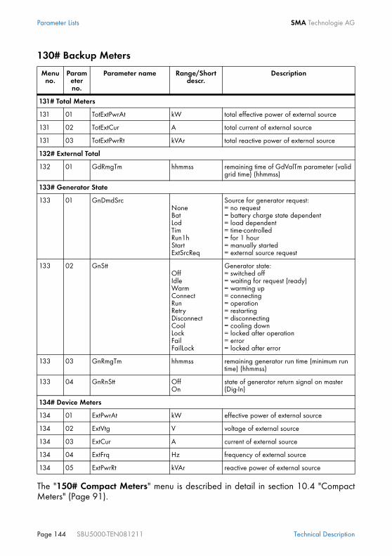
Parameter Lists SMA Technologie AG
Page 144 SBU5000-TEN081211 Technical Description
130# Backup Meters
The "150# Compact Meters" menu is described in detail in section 10.4 "CompactMeters" (Page 91).
Menu no.
Parameter no.
Parameter name Range/Short descr.
Description
131# Total Meters
131 01 TotExtPwrAt kW total effective power of external source
131 02 TotExtCur A total current of external source
131 03 TotExtPwrRt kVAr total reactive power of external source
132# External Total
132 01 GdRmgTm hhmmss remaining time of GdValTm parameter (valid grid time) (hhmmss)
133# Generator State
133 01 GnDmdSrcNoneBatLodTimRun1hStartExtSrcReq
Source for generator request:= no request= battery charge state dependent= load dependent= time-controlled= for 1 hour= manually started= external source request
133 02 GnSttOffIdleWarmConnectRunRetryDisconnectCoolLockFailFailLock
Generator state:= switched off= waiting for request (ready)= warming up= connecting= operation= restarting= disconnecting= cooling down= locked after operation= error= locked after error
133 03 GnRmgTm hhmmss remaining generator run time (minimum run time) (hhmmss)
133 04 GnRnStt OffOn
state of generator return signal on master (Dig-In)
134# Device Meters
134 01 ExtPwrAt kW effective power of external source
134 02 ExtVtg V voltage of external source
134 03 ExtCur A current of external source
134 04 ExtFrq Hz frequency of external source
134 05 ExtPwrRt kVAr reactive power of external source

SMA Technologie AG Parameter Lists
Technical Description SBU5000-TEN081211 Page 145
19.2 Adjustable System Parameters
210# Inverter Settings
220# Battery Settings
Parameters marked with (Stby) are to be changed only when the Sunny Backup5000 is in standby mode. Once the "ENTER" button is pressed, operating datavalues can immediately change to their new settings. Incorrect values in theseparameters can probably not be corrected quickly enough to avoid potentialdamage to your system.All menu items that can only be changed after entering the installer password areshaded in gray in the following tables.All parameters can be set using a connected PC/laptop with the Sunny DataControl software, a Sunny WebBox or a Sunny Boy Control (see section 6.5"Interface for External Communication" (Page 58)).
Menu no.
Parameter no.
Parameter name Range/Short descr.
Value Description
210 02 InvChrgCurMax A 20 maximum device charging current
Menu no.
Parameter no.
Parameter name Range/Short descr.
Default value
Description
221# Battery Property
221 01 BatTypVRLAFLANiCd
VRLA Battery type:= valve regulated lead acid= flooded lead acid= nickel cadmiumcan only be changed in QCG
221 02 BatCpyNom Ah 100 nominal battery capacity (C10)can only be changed in QCG
221 03 BatVtgNom V 48 Nominal battery voltage:48 = VRLA48 = FLA45.6 = NiCdcan only be changed in QCG
221 04 BatTmpMax degC 40 maximum battery temperature
221 05 BatTmpStr degC 35 battery restart temperature following stop due to overtemperature
221 06 ChrgCtlOpAutoNoFrqSMA
Auto DC charger type= automatic= no frequency shift control of AC sources= like Auto, plus SMA-compliant DC chargers (e.g. CC40)

Parameter Lists SMA Technologie AG
Page 146 SBU5000-TEN081211 Technical Description
222# Battery Charge Mode
222 01 BatChrgCurMax A 1200 battery charging current limit (depends on nominal battery capacity), 60 % of the nominal battery capacity (#221.02)
222 02 AptTmBoost min 120 Boost charge absorption time:120 = VRLA90 = FLA300 = NiCddepending on the setting in QCG
222 03 AptTmFul h 5 Absorption time for full charge:5 = VRLA5 = FLA7 = NiCddepending on the setting in QCG
222 04 AptTmEqu h 10 Absorption time for equalization charge:10 = VRLA10 = FLA10 = NiCddepending on the setting in QCG
222 05 CycTmFul d 14 full charge cycle time
222 06 CycTmEqu d 180 equalization charge cycle time
222 07 ChrgVtgBoost V 2.4 Cell voltage nominal value for boost charge:2.4 = VRLA2.55 = FLA1.65 = NiCddepending on the setting in QCG
222 08 ChrgVtgFul V 2.4 Cell voltage nominal value for full charge:2.4 = VRLA2.5 = FLA1.65 = NiCddepending on the setting in QCG
222 09 ChrgVtgEqu V 2.4 Cell voltage nominal value for equalization charge:2.4 = VRLA2.5 = FLA1.65 = NiCddepending on the setting in QCG
222 10 ChrgVtgFlo V 2.25 Cell voltage nominal value for float charge:2.25 = VRLA2.25 = FLA1.55 = NiCddepending on the setting in QCG
Menu no.
Parameter no.
Parameter name Range/Short descr.
Default value
Description

SMA Technologie AG Parameter Lists
Technical Description SBU5000-TEN081211 Page 147
222 11 BatTmpCps mV/degC 4.0 battery temperature compensationAbsorption time for full charge:4.0 = VRLA4.0 = FLA0.0 = NiCddepending on the setting in QCG
222 12 AutoEquChrgEna DisableEnable
Enable activates automatic equalization charge
223# Battery Protect Mode
223 01 BatPro1TmStr hhmmss 220000 time for starting battery preservation mode level 1
223 02 BatPro1TmStp hhmmss 060000 time for stopping battery preservation mode level 1
223 03 BatPro2TmStr hhmmss 170000 time for starting battery preservation mode level 2
223 04 BatPro2TmStp hhmmss 090000 time for stopping battery preservation mode level 2
223 05 BatPro1Soc % 20 SOC limit for preservation mode level 1
223 06 BatPro2Soc % 10 SOC limit for preservation mode level 2
223 07 BatPro3Soc % 0 SOC limit for preservation mode level 3
224# Battery Silent Mode
224 01 SilentEna DisableEnable
Disable allows silent mode on the grid
224 02 SilentTmFlo(Stby)
h 3 max. time for float charge until transfer into silent
224 03 SilentTmMax(Stby)
h 12 max. time for silent mode until transfer into float
#225 Battery Current Sensor
#225 01 BatCurSnsTyp None60mV50mV
None Stromsensortyp
#225 02 BatCurGain60 A/60mV 100 Externer Batteriestromsensor 60 mV-Typ
#225 03 BatCurGain50 A/50mV 100 Externer Batteriestromsensor 50 mV-Typ
#225 04 BatCurAutoCal Start Autokalibrierung des externen Batte-riestromsensors
Menu no.
Parameter no.
Parameter name Range/Short descr.
Default value
Description

Parameter Lists SMA Technologie AG
Page 148 SBU5000-TEN081211 Technical Description
230# Backup Settings
Menu no.
Parameter no.
Parameter name Range/Short descr.
Default value
Description
231# General
231 01 PvFeedTmStr hhmmss 040000 start time for PV grid feeding
231 02 PvFeedTmStp hhmmss 220000 stop time for PV grid feeding
231 03 ExtLkTm min 20 lock time after reverse power or relay protection
231 04 AcSrcFrqDel Hz 4.8 frequency increase for disconnecting AC feed-in generators
231 09 ExtSrcPvOnlyGenGridGenGrid
Grid Generator and grid operating mode:= PV only= grid= ext. sources= grid and ext. sources
231 13 PvInst DisableEnable
Enable PV installed
231 14 TotPvPwr kW total installed PV power
231 15 ClstPwrNom kW 5 nominal cluster power output
232# Grid Control
232 01 GdVtgMin * V 187 minimum grid voltage
232 02 GdVtgMax * V 261.5 maximum grid voltage
232 03 GdCurNom A 16 nominal grid current
232 04 GdFrqNom Hz 50 nominal grid frequency
232 05 GdFrqMin * Hz 47.65 minimum grid frequency
232 06 GdFrqMax * Hz 50.15 maximum grid frequency
232 07 GdVldTm sec 30 minimum time required for grid (voltage and frequency) to be within permissible range for connection
232 08 GdMod GridChargeGridFeed
GridCharge grid interface
232 09 GdRvPwr W 100 permissible grid reverse power (effective power)
232 10 GdRvTm sec 5 permissible time for grid reverse power
232 18 GdVtgIncProEna DisableEnable
Enable allows voltage rise protection
232 19 GdVtgIncPro V 253 threshold for voltage rise protection

SMA Technologie AG Parameter Lists
Technical Description SBU5000-TEN081211 Page 149
232 40 Country GER_VDE0126_1_1;AUS_AS4777
GER_VDE0126_1_1
country selection
232 41 FedInMod OffTimeSignalCom
Off Feeding of energy depending on time, digital signal or communication (This function is intended for future applications.)
232 42 FedInSocStr % 40 Minimal SOC where feeding is started
232 43 FedInSocStp % 20 Minimal SOC where feeding is stopped
232 44 FedInTmStr hhmmss 0 Start time dependent grid feeding
232 45 FedInTmStp hhmmss 0 Stop time dependent grid feeding
232 46 FedInCurAt A 16 Active feeding current per phase
232 47 FedInCurRt A 0 Reactive feeding current per phase
233# Generator Control
233 01 GnVtgMin V 172.5 minimum generator voltage
233 02 GnVtgMax V 250 maximum generator voltage
233 03 GnCurNom A 16 nominal generator current
233 04 GnFrqNom Hz 50 nominal generator frequency (at nominal load)
233 05 GnFrqMin Hz 44.64 minimum generator frequency
233 06 GnFrqMax Hz 60 maximum generator frequency
233 07 GnStrMod ManualAutostartGenMan
Autostart generator interface
233 08 GnOpTmMin min 15 minimum generator run time
233 09 GnStpTmMin min 15 minimum generator stop time
233 10 GnCoolTm min 5 generator cooling-off time
233 11 GnErrStpTm h 1 generator stop time for generator fault
233 12 GnWarmTm sec 60 warm up time (minimum time required for generator voltage and frequency to be within permissible range for connection)
233 13 GnRvPwr W 100 permissible generator reverse power (effective power)
233 14 GnRvTm sec 30 permissible time for reverse power/reverse current
Menu no.
Parameter no.
Parameter name Range/Short descr.
Default value
Description

Parameter Lists SMA Technologie AG
Page 150 SBU5000-TEN081211 Technical Description
233 15 ExtCtlMod CurCurFrq
Cur ext. (gen/grid) controller (current or frequency)
234# Generator Start
234 01 GnAutoEna OffOn
On activate generator autostart
234 02 GnAutoStr 3 number of autostarts
234 03 GnSocTm1Str % 40 SOC limit for switching on generator for time 1
234 04 GnSocTm1Stp % 80 SOC limit for switching off generator for time 1
234 05 GnSocTm2Str % 40 SOC limit for switching on generator for time 2
234 06 GnSocTm2Stp % 80 SOC limit for switching off generator for time 2
234 07 GnTm1Str hhmmss 0 time 1 for generator request (begin time 1, end time 2) (hhmmss)
234 08 GnTm2Str hhmmss 0 time 2 for generator request (begin time 2, end time 1) (hhmmss)
234 09 GnPwrEna OffOn
Off activate generator request as a result of power
234 10 GnPwrStr kW 4 activates generator as a result of power limit
234 11 GnPwrStp kW 2 deactivates generator as a result of power limit
234 12 GnPwrAvgTm sec 60 average time for power-related generator start
Parameters designated with * are safety-related grid monitoring parameters. Tochange the SMA grid guard parameters, you must enter your personal SMA gridguard password (Inst.-Code). Call the SMA Hotline to obtain your personal SMAgrid guard password.
Menu no.
Parameter no.
Parameter name Range/Short descr.
Default value
Description

SMA Technologie AG Parameter Lists
Technical Description SBU5000-TEN081211 Page 151
240# Relay Settings
Menu no.
Parameter no.
Parameter name Range/Short descr.
Default value
Description
241# Relay General
241 01 Rly1OpOffOnAutoGn
AutoLodExt
AutoLod1Soc
AutoLod2Soc
Tmr1Tmr2AptPhsGnRnExtVfOk
GdOnErrorWarmRunEns1Ens2BatFanAcdCir
AutoGn Function of relay 1:= switched off= switched on= automatic generator connection= automatic load disconnection, only activated if external sources are present= automatic connection / disconnection of loads due to SOC1= automatic connection / disconnection of loads due to SOC2= programmable timer 1= programmable timer 1= absorption phase is active= generator is running= ext. voltage and frequency in permissible range= ext. grid is connected= error= warmup= operation(= currently has no function)(= currently has no function)= battery room fan= electrolyte pump
241 02 Rly2Op see 261.01 AutoLodExt Function of relay 2:for details, see 241.01
242# Relay Load
242 01 Lod1SocTm1Str % 30 SOC limit for load shedding 1 start for t1
242 02 Lod1SocTm1Stp % 50 SOC limit for load shedding 1 stop for t1
242 03 Lod1SocTm2Str % 30 SOC limit for load shedding 1 start for t2
242 04 Lod1SocTm2Stp % 50 SOC limit for load shedding 1 stop for t2
242 05 Lod1Tm1Str hhmmss 0 load shedding 1 time 1(begin time 1, end time 2)
242 06 Lod1Tm2Str hhmmss 0 load shedding 1 time 2(begin time 2, end time 1)
242 07 Lod2SocTm1Str % 30 SOC limit for load shedding 2 start for t1
242 08 Lod2SocTm1Stp % 50 SOC limit for load shedding 2 stop for t1

Parameter Lists SMA Technologie AG
Page 152 SBU5000-TEN081211 Technical Description
242 09 Lod2SocTm2Str % 30 SOC limit for load shedding 2 start for t2
242 10 Lod2SocTm2Stp % 50 SOC limit for load shedding 2 stop for t2
242 11 Lod2Tm1Str hhmmss 0 load shedding 2 time 1(begin time 1, end time 2)
242 12 Lod2Tm2Str hhmmss 0 load shedding 2 time 2(begin time 2, end time 1)
243# Relay Timer
243 01 RlyTmr1StrDt yyyymmdd 20060101 start date timer 1
243 02 RlyTmr1StrTm hhmmss 0 start time for relay controltimer 1 (hhmmss)
243 03 RlyTmr1Dur hhmmss 0 run time for relay control timer 1 (hhmmss)
243 04 RlyTmr1Cyc SingleDailyWeekly
Single repeated cycle time for timer 1
243 05 RlyTmr2StrDt yyyymmdd 20060101 start date timer 2
243 06 RlyTmr2StrTm hhmmss 0 start time for relay control timer 2 (hhmmss)
243 07 RlyTmr2Dur hhmmss 0 run time for relay control timer 2 (hhmmss)
243 08 RlyTmr2Cyc SingleDailyWeekly
Single repeated cycle time forrelay 2
Menu no.
Parameter no.
Parameter name Range/Short descr.
Default value
Description

SMA Technologie AG Parameter Lists
Technical Description SBU5000-TEN081211 Page 153
250# System Settings
The „260# Password Setting" menu is described in detail in section 10.5 "Entering theInstaller Password" (Page 94).
Menu no.
Parameter no.
Parameter name Range/Short descr.
Default value
Description
250 01 AutoStr(Stby)
0 autostart (0 = autostart deactivated)
250 02 Dt yyyymmdd date (yyyymmdd)
250 03 Tm hhmmss time (hhmmss)
250 04 BeepEna OffOn
On activates beeper
250 05 ClstCfg cluster configurationfrom QCG, read only
250 06 ComBaud 12004800960019200
1200 baud rate interface
250 07 ComItrf SerialCAN
Serial interface
250 08 ComPtcl SMA-DataCANCAN-Open
SMA-Data interface protocol
250 09 ComAdr interface address
250 10 SleepEna DisableEnable
Enable allows sleep mode

Parameter Lists SMA Technologie AG
Page 154 SBU5000-TEN081211 Technical Description
19.3 Diagnostics310# Inverter Diagnosis
Menu no.
Parameter no.
Parameter name Range/Short descr.
Description
311# Total System Diag
311 01 EgyCntIn kWh energy absorbed
311 02 EgyCntOut kWh energy fed
311 03 EgyCntTm h energy metering run time
312# Inverter Device Diag
312 01 Adr MasterSlave1Slave2Slave3
device address (type)depending on the setting in QCG
312 02 FwVer BFR firmware version
312 03 SN serial number
312 04 OnTmh h operating hours
312 05 ClstCfgAt 1Phase11Phase21Phase31Phase42Phase23Phase2Phase4
set cluster configurationdepending on the setting in QCG
312 06 OpStt OperatingWarningFailure
operating mode (device)
312 07 CardSttOffOperationalMountOutOfSpace
BadFileSysIncompParameterParamFailedWriteLogDataWriteLogFailed
MMC/SD card status message:= none Sunny Backup 5000= in operation= card initializing= insufficient memory capacity (on card or in main directory)= incorrect file system= incompatible card= parameter update is active= error during parameter update= writing log data to card= error upon writing log data to card
312 08 FwVer2 DSP firmware version
312 09 FwVer3 BFR boot loader
312 10 FwVer4 DSP boot loader

SMA Technologie AG Parameter Lists
Technical Description SBU5000-TEN081211 Page 155
320# Battery Diagnosis
330# Backup Diagnosis
Menu no.
Parameter no.
Parameter name Range/Short descr.
Description
320 01 Soh % state of health (SOH), ratio of current capacity and nominal value
320 02 StatTm d statistics metering run time
320 03 ChrgFact charging factor
320 04 BatEgyCntIn kWh energy meter for battery charge
320 05 BatEgyCntOut kWh energy meter for battery discharge
320 06 AhCntIn Ah meter for battery charging ampere hours
320 07 AhCntOut Ah meter for battery discharging ampere hours
320 08 BatTmpPkMin degC minimum battery temperature
320 09 BatTmpPkMax degC maximum battery temperature
320 10 EquChrgCnt equalization charge meter
320 11 FulChrgCnt full charge meter
320 12 BatCurOfsErr A current offset error of battery current
320 13 OcvPointCnt meter for open-circuit voltage points
320 14 SilentReq OffOn
silent mode request
Menu no.
Parameter no.
Parameter name Range/Short descr.
Description
331# Grid Diag
331 01 GdEgyCntIn kWh energy meter for grid feed-in
331 02 GdEgyCntOut kWh energy meter for power taken from the grid
331 03 GdEgyTmh h run time of grid energy meter
331 04 GdOpTmh h operating hour meter for grid operation
331 05 GdCtcCnt meter for grid connections
331 06 TotTmh h feed-in hours
332# Generator Diag
331 01 GnEgyCnt kWh generator energy meter
331 02 GnEgyTm h run time of generator energy meter
331 03 GnOpTmh h operating hour meter for generator
331 04 GnStrCnt number of generator starts

Parameter Lists SMA Technologie AG
Page 156 SBU5000-TEN081211 Technical Description
19.4 Events, Warnings and Errors (History)Information on events and error messages [410# Failures Current, 420# FailureHistory and 430# Event History are provided as of section 20.5 "Display of Errorsand Events" (Page 160).
19.5 Functions in Operation510# Operation Inverter
520# Operation Battery
Menu no.
Parameter no.
Parameter name Range/Short descr.
Default value
Description
510 01 InvRs(Stby)
Restart --- triggers inverter reset
510 02 ParaStoSet1Set2
--- Saves parameter settings:= file 1= file 2
510 03 InvTmOpEna DisableEnable
Disable activates time-controlled inverter operation
510 04 InvTmOpStrDt yyyymmdd 20060101 start date of time-controlled inverter operation (yyyymmdd)
510 05 InvTmOpStrTm hhmmss 0 start time of time-controlled inverter operation (hhmmss)
510 06 InvTmOpRnDur hhmmss 0 run time for time-controlled inverter operation (hhmmss)
510 07 InvTmOpCyc SingleDailyWeekly
Single repeated cycle time for timer 1
510 08 ParaLod(Stby) Set1
Set2Factory
--- Loads parameter settings:= file 1= file 2= factory settings
510 09 CntRs InvBatGnGdAll
--- clears selected energy meter
Menu no.
Parameter no.
Name Range/Short descr.
Default Description
520 01 ManChrgSel IdleStartStop
Idle triggers equalization charge (manual)

SMA Technologie AG Parameter Lists
Technical Description SBU5000-TEN081211 Page 157
530# Operation Backup
540# Operation Generator
550# Operation MMC/SD Card
The 600# Direct Access menu is described in detail in section 10.3 "Direct Access"(Page 91).
Menu no.
Parameter no.
Parameter name Range/Short descr.
Default value
Description
530 02 BkupTst StopStart
backup system test
Menu no.
Parameter no.
Parameter name Range/Short descr.
Default value
Description
540 01 GnManStr AutoStopStartRun1hManEquChrg
Stop manual generator start
540 02 GnAck Ackn error confirmation for generator fault
Menu no.
Parameter no.
Name Range/Short descr.
Default Description
550 01 CardFuncForcedWriteStoEvtHisStoFailHis
Functions for MMC/SD card:= forces writing of data= writes event list= writes error list
550 02 DatLogEna OffOn
On activates automatic data storage

Parameter Lists SMA Technologie AG
Page 158 SBU5000-TEN081211 Technical Description

SMA Technologie AG Troubleshooting/Problem Solving
Technical Description SBU5000-TEN081211 Page 159
20 Troubleshooting/Problem SolvingIn principle, the Sunny Backup 5000 makes a distinction between events and errors.• Events describe state changes or transient states (e.g. generator connection).• Errors describe impermissible or only limited permissible states. This includes
warnings, failures and errors. A user interaction is generally required.
20.1 Error ConfirmationIf a fault occurs, the Sunny Backup 5000 goes into standby mode and the fault is shownon the display. You must remedy the cause of the fault using <ENTER> and the Sunny Backup 5000restarts.
20.2 Autostart HandlingThe Sunny Backup 5000 has an autostart meter that counts down by 1 for eachautostart. If the Sunny Backup 5000 runs uninterrupted for over 10 minutes, theautostart meter is reset to its initial value.If another fault occurs when the autostart meter is at 0, the Sunny Backup 5000 waitsfor 10 minutes and then attempts to restart. The autostart meter begins to run again.The number of the autostarts allowed can be set using the "250.01 AutoStr" parameter(in standby mode).
20.3 Master Slave HandlingEach device detects the faults separately and saves it. The slaves transfer their errors tothe master. The master collects these error messages and enters the slave errors aswarnings into its history.
If error 138 is still active on slave 1, the Enter symbol appears at the end. Afterconfirming the fault on the master using <ENTER>, the fault is forwarded to thecorresponding slave.
Slave 1 has detected an overtemperature fault (F138). It enters this error in itshistory and reports it to the master, which also enters it as a warning into its failurehistory ("Menu 320# Failure History").
The following message appears in the lower line on themaster:
F138 S1 Warning

Troubleshooting/Problem Solving SMA Technologie AG
Page 160 SBU5000-TEN081211 Technical Description
20.4 Handling Pending Errors During the Booting ProcedureDuring the booting procedure, all pending errors are generally confirmed without anentry being made in the history. This way, an error that is still pending after the bootingprocedure is re-entered or if the system detects that this error has stopped, it is enteredas no longer being present.
20.5 Display of Errors and EventsEach error and each event have a unique three-digit display number that is createdaccording to the parameter/measuring value assignment. The events and errors havethe identical numerical range:• 1xx - INV - Inverter• 2xx - BAT - Battery• 3xx - EXT - Extern• 4xx - GEN - Generator• 5xx - GRD - Grid• 6xx - RLY - Relay• 7xx - SYS - System• 8xx - BOX - Automatic Switch Box
Display on the master after confirmation:
The error and event memory are not compared between the master and slaves.
"F" marks an error, "W" marks a warning and "E" marks an event.In the event of an error, and provided it is recorded, "!" is displayed for an errorthat has occurred and "C" is displayed for an error that has stopped.
F138 S1 Warning
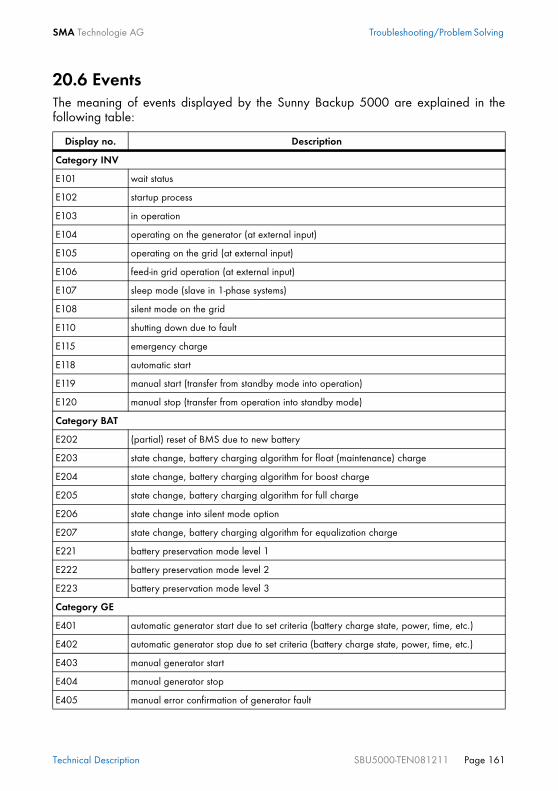
SMA Technologie AG Troubleshooting/Problem Solving
Technical Description SBU5000-TEN081211 Page 161
20.6 EventsThe meaning of events displayed by the Sunny Backup 5000 are explained in thefollowing table:
Display no. Description
Category INV
E101 wait status
E102 startup process
E103 in operation
E104 operating on the generator (at external input)
E105 operating on the grid (at external input)
E106 feed-in grid operation (at external input)
E107 sleep mode (slave in 1-phase systems)
E108 silent mode on the grid
E110 shutting down due to fault
E115 emergency charge
E118 automatic start
E119 manual start (transfer from standby mode into operation)
E120 manual stop (transfer from operation into standby mode)
Category BAT
E202 (partial) reset of BMS due to new battery
E203 state change, battery charging algorithm for float (maintenance) charge
E204 state change, battery charging algorithm for boost charge
E205 state change, battery charging algorithm for full charge
E206 state change into silent mode option
E207 state change, battery charging algorithm for equalization charge
E221 battery preservation mode level 1
E222 battery preservation mode level 2
E223 battery preservation mode level 3
Category GE
E401 automatic generator start due to set criteria (battery charge state, power, time, etc.)
E402 automatic generator stop due to set criteria (battery charge state, power, time, etc.)
E403 manual generator start
E404 manual generator stop
E405 manual error confirmation of generator fault

Troubleshooting/Problem Solving SMA Technologie AG
Page 162 SBU5000-TEN081211 Technical Description
Category REL
E601 relay 1 off
E602 relay 1 on
E603 relay 1 on slave 1 off
E604 relay 1 on slave 1 on
E605 relay 1 on slave 2 off
E606 relay 1 on slave 2 on
E607 relay 1 on slave 3 off
E608 relay 1 on slave 3 on
E609 transfer relay open
E610 transfer relay closed
E611 transfer relay on slave 1 open
E612 transfer relay on slave 1 closed
E613 transfer relay on slave 2 open
E614 transfer relay on slave 2 closed
E615 transfer relay on slave 3 open
E616 transfer relay on slave 3 closed
E617 relay 2 open
E618 relay 2 closed
E619 relay 2 on slave 1 open
E620 relay 2 on slave 1 closed
E621 relay 2 on slave 2 open
E622 relay 2 on slave 2 closed
E623 relay 2 on slave 3 open
E624 relay 2 on slave 3 closed
E625 digital input OFF (Low)
E626 digital input ON (High)
Category SYS
E705 device start
E706 date, time changed
E707 new system configured in QCG
E708 part 1 of the firmware updated
E709 part 2 of the firmware updated
E710 cluster firmware updated
Display no. Description

SMA Technologie AG Troubleshooting/Problem Solving
Technical Description SBU5000-TEN081211 Page 163
20.7 Error CategoriesThe Sunny Backup 5000 categorizes errors into five different levels. There is a differentbehavior depending on the level:
20.8 Warnings and Error MessagesThe meaning of warnings and error messages displayed by the Sunny Backup 5000are explained in the following table:
E711 MMC/SD card inserted
Level Display Meaning
1 Warning Warning, device continues to run. There is an explicit note on the Home Screen that a warning was recorded.
2 Malfunction Failure that can only be detected during operation. Device switches off. Device can be restarted immediately (autostart).
3 Malfunction Failure that can also be detected in standby mode. Device switches off. The device can only be restarted (autostart) after the system detects that the failure has stopped.
4 Failure Device fault. Device switches off. User interaction required (troubleshooting, confirmation, manual restart).
5 Failure Device is defect. Device switches off and does not switch on again. Permanent disable. Device must be replaced.
Displ. no.
Level Description
Category INV
F109 3 overheating on transformer
W110 1 overheating on transformer on slave 1
W111 1 overheating on transformer on slave 2
W112 1 overheating on transformer on slave 3
F113 3 overheating on heatsink
W114 3 overheating on heatsink on slave 1
W115 3 overheating on heatsink on slave 2
W116 3 overheating on heatsink on slave 3
F117 2 AC current limit (short-circuit control active for too long)
W118 2 AC current limit (short-circuit control active for too long) on slave 1
W119 2 AC current limit (short-circuit control active for too long) on slave 2
W120 2 AC current limit (short-circuit control active for too long) on slave 3
F121 3 inverter overvoltage
Display no. Description

Troubleshooting/Problem Solving SMA Technologie AG
Page 164 SBU5000-TEN081211 Technical Description
W122 3 inverter overvoltage on slave 1
W123 3 inverter overvoltage on slave 2
W124 3 inverter overvoltage on slave 3
W137 1 derating due to temperature (heatsink or transformer)
W138 1 derating due to temperature (heatsink or transformer) on slave 1
W139 1 derating due to temperature (heatsink or transformer) on slave 2
W140 1 derating due to temperature (heatsink or transformer) on slave 3
Category BAT
F201 3 measuring range of battery voltage exceeded
W202 3 measuring range of battery voltage exceeded on slave 1
W203 3 measuring range of battery voltage exceeded on slave 2
W204 3 measuring range of battery voltage exceeded on slave 3
W206 1 battery overheating
W208 3 battery overvoltage (fixed limit for cell voltage)
W210 1 battery overvoltage warning
W211 1 insufficient battery temperature warning
W212 1 high battery temperature warning
Category EXT
W309 1 relay protection
W310 1 relay protection on slave 1
W311 1 relay protection on slave 2
W312 1 relay protection on slave 3
W314 1 external voltage failure
W315 1 grid/generator disconnection due to insufficient external voltage
W316 1 grid/generator disconnection due to insufficient external voltage on slave 1
W317 1 grid/generator disconnection due to insufficient external voltage on slave 2
W318 1 grid/generator disconnection due to insufficient external voltage on slave 3
W319 1 grid/generator disconnection due to excessive external voltage
W320 1 grid/generator disconnection due to excessive external voltage on slave 1
W321 1 grid/generator disconnection due to excessive external voltage on slave 2
W322 1 grid/generator disconnection due to excessive external voltage on slave 3
W323 1 grid/generator disconnection due to insufficient external frequency
W324 1 grid/generator disconnection due to insufficient external frequency on slave 1
Displ. no.
Level Description

SMA Technologie AG Troubleshooting/Problem Solving
Technical Description SBU5000-TEN081211 Page 165
W325 1 grid/generator disconnection due to insufficient external frequency on slave 2
W326 1 grid/generator disconnection due to insufficient external frequency on slave 3
W327 1 grid/generator disconnection due to excessive external frequency
W328 1 grid/generator disconnection due to excessive external frequency on slave 1
W329 1 grid/generator disconnection due to excessive external frequency on slave 2
W330 1 grid/generator disconnection due to excessive external frequency on slave 3
W331 1 grid/generator disconnection due to anti-islanding
W332 1 grid/generator disconnection due to anti-islanding on slave 1
W333 1 grid/generator disconnection due to anti-islanding on slave 2
W334 1 grid/generator disconnection due to anti-islanding on slave 3
W335 1 grid/generator disconnection due to breached voltage limits
W336 1 grid/generator disconnection due to breached voltage limits on slave 1
W337 1 grid/generator disconnection due to breached voltage limits on slave 2
W338 1 grid/generator disconnection due to breached voltage limits on slave 3
F343 1 disconnection from external source
F344 1 disconnection from external source on slave 1
F345 1 disconnection from external source on slave 2
F346 1 disconnection from external source on slave 3
Category GEN
W401 1 reverse power protection (generator)
Category GRD
W501 1 grid reverse current prohibited (quick grid disconnection)
W502 1 grid reverse current prohibited (quick grid disconnection) on slave 1
W503 1 grid reverse current prohibited (quick grid disconnection) on slave 2
W504 1 grid reverse current prohibited (quick grid disconnection) on slave 3
Category SYS
F702 1 DSP reset
F703 1 timeout during a task
F705 4 DSP watchdog has been triggered
F706 4 watchdog meter has expired (watchdog triggered several times in succession)
W707 4 watchdog meter on slave 1 has expired (watchdog triggered several times in succession)
W708 4 watchdog meter on slave 2 has expired (watchdog triggered several times in succession)
W709 4 watchdog meter on slave 3 has expired (watchdog triggered several times in succession)
Displ. no.
Level Description

Troubleshooting/Problem Solving SMA Technologie AG
Page 166 SBU5000-TEN081211 Technical Description
F710 4 autostart meter has expired (several autostarts in succession)
W713 1 watchdog has been triggered
F716 3 measuring range of battery voltage exceeded
W717 3 measuring range of battery voltage exceeded on slave 1
W718 3 measuring range of battery voltage exceeded on slave 2
W719 3 measuring range of battery voltage exceeded on slave 3
F720 4 short circuit or cable break on transformer temperature sensor
F721 4 short circuit or cable break on heatsink temperature sensor
F722 3 short circuit in battery temperature sensor
F723 3 cable break on battery temperature sensor
F731 3 error in the cluster configuration
F732 3 error in address assignment of cluster device
F733 3 no message from cluster master (only slave)
W734 3 no message from cluster on slave 1
W735 3 no message from cluster on slave 2
W736 3 no message from cluster on slave 3
W738 1 synchronization not successful
F739 3 internal device communication BFR-DSP missing
W740 3 internal device communication BFR-DSP on slave 1 missing
W741 3 internal device communication BFR-DSP on slave 2 missing
W742 3 internal device communication BFR-DSP on slave 3 missing
F743 3 internal device communication BFR-DSP missing
W744 3 internal device communication BFR-DSP on slave 1 missing
W745 3 internal device communication BFR-DSP on slave 2 missing
W746 3 internal device communication BFR-DSP on slave 3 missing
W747 4 short circuit or cable break on transformer temperature sensor on slave 1
W748 4 short circuit or cable break on transformer temperature sensor on slave 1
W749 4 short circuit or cable break on transformer temperature sensor on slave 2
W750 4 short circuit or cable break on heatsink temperature sensor on slave 2
W751 4 short circuit or cable break on heatsink temperature sensor on slave 3
W752 4 short circuit or cable break on heatsink temperature sensor on slave 3
F753 1 invalid system time
Displ. no.
Level Description

SMA Technologie AG Troubleshooting/Problem Solving
Technical Description SBU5000-TEN081211 Page 167
Category BOX
F801 3 box fault
W802 1 PV system not available
W803 1 PV system not available for grid feeding
W804 1 no grid operation
W805 1 no generator operation
F806 4 box type (Sunny Backup 5000) and box type (Automatic Switch Box) do not match
W807 1 external voltage is invalid
Displ. no.
Level Description

Troubleshooting/Problem Solving SMA Technologie AG
Page 168 SBU5000-TEN081211 Technical Description
20.9 TroubleshootingAnswers are provided below for faults that may occur in practice:
1. ApprovalThe grid operator refuses to allow connection of the system to the grid due toconcern that this would enable feeding of arbitrary current back through thefeed-in counter. Is this legitimate?No, if all system components are connected correctly, only energy which is fed in atconnection X4 / PV System can be forwarded to the output X5 / PV Meter. Aconnection from the Sunny Backup 5000 to the PV feed-in counter is prevented by thesoftware, and also by the hardware locks in the box.
2. Installation / CommissioningWhy do I need to install a fuse in the Automatic Switch Box? The cable from thegrid is already fused in the meter cabinet!So that the cable from the Automatic Switch Box to the consumer system is protectedagainst overload in stand-alone operation. The Sunny Backup 5000 and the PV systemcombined can supply more power than is provided for on the grid side.Why do thermal fuses need to be installed in the Automatic Switch Box? Thesedays, only automatic breakers are used!For two reasons: firstly, you must select the nominal fuse rating according to the system'slocal conditions, thus SMA Technologie AG cannot install a line circuit breaker with afixed nominal rating. Secondly, if a line circuit breaker were installed, in the event of ashort circuit during feeding from a rigid grid (high short-circuit currents!), there would beno selectivity between that line circuit breaker and the line circuit breakers in the sub-distribution unit, even if it were to have a higher nominal rating. However, there isselectivity between thermal fuses and line circuit breakers, so that upon a short circuitin the final circuit, only the fuse in the final circuit blows, and not the fuse in theAutomatic Switch Box as well.How do I dimension the thermal fuses in the Automatic Switch Box?The dimensioning of the thermal fuse at the loads output (X3 / Backup Loads) is madeeasier by the following recommendations:• A: The rating of the back-up fuse in the meter cabinet is equal to the nominal
current of the Automatic Switch Box during grid operation.- For the Automatic Switch Box, a fuse must be installed with a rating which
corresponds to the nominal current of the Automatic Switch Box (35 A forAutomatic Switch Box M, 63 A for L, and 160 A for XL).
• B: The rating of the back-up fuse in the meter cabinet is lower than the nominalcurrent of the Automatic Switch Box during grid operation.- The fuse to be installed must be the same as in the meter cabinet.

SMA Technologie AG Troubleshooting/Problem Solving
Technical Description SBU5000-TEN081211 Page 169
- The maximum current drawn from the grid (parameter "232.03 GdCurNom")is to be set to the rating of the back-up fuse.
• C: The rating of the back-up fuse in the meter cabinet is higher than the nominalcurrent of the Automatic Switch Box in grid operation, and the cables are designedfor larger currents accordingly.- There is a danger of overloading the Automatic Switch Box. If possible, install
a fuse, with a rating equal to the nominal current of the Automatic Switch Box,in the meter cabinet at the output leading to the Automatic Switch Box.
- For the Automatic Switch Box, a fuse must be installed with a rating whichcorresponds to the nominal current of the Automatic Switch Box (35 A forAutomatic Switch Box M, 63 A for L, and 160 A for XL).
Why am I prohibited from installing an RCD upstream of the Sunny Backupsystem?Because the RCD has a protective function (voltage disconnection in the event of a fault)which is rendered ineffective by the Sunny Backup system. In order to preserve thisprotective function, the RCD must be positioned between the Automatic Switch Box andthe loads.Why do I need the PEN conductor to be grounded upstream of the SunnyBackup system, yet still within the system? The PEN conductor is alreadygrounded in the local grid!In the event of a deliberate grid shutdown on the part of your distribution grid operator(e.g. for maintenance work), the PEN conductor can be interrupted if the correspondingphase conductors are disconnected. The Sunny Backup system then lacks a groundconnection, which is unacceptable, both in terms of functionality and safety.Furthermore, an increase of the PEN conductor's voltage in the grid is prevented instand-alone operation.At our site, there is only a TT grid, and my distribution grid operator does notallow the N conductor to be grounded. Can I operate the Sunny Backup systemanyway, without grounding the N conductor?NO, in this form, the system is only certified for TT grids. Consult your energy supplycompany to ascertain the conditions under which installation is permissible.What happens if three-phase loads remain connected in a single-phase SunnyBackup system (e.g. Automatic Switch Box M)?In this case, both the X1 / Load Meter and X3 / Backup Loads connections must beimplemented as three-phase connections. Thus, three-phase grid disconnection occurs,but in the event of grid failure, power supply continues only at phase L1. This meansthat reverse voltage on the grid side is not possible. If the three-phase loads are star-connected, these continue to be powered on just asingle phase. For electric kitchen stoves, which often have a three-phase connection,this is not at all problematic. In motors which are nevertheless connected, and whichare protected by a motor overload switch, this motor overload switch will generally be
Troubleshooting/Problem Solving SMA Technologie AG
Page 170 SBU5000-TEN081211 Technical Description
triggered. Otherwise, the motor will either not start at all, or will operate veryirregularly, and should be deactivated again immediately because otherwise the SunnyBackup system may deactivate due to overloading.With three-phase delta-connected loads (e.g. electric continuous-flow heaters) whichare kept in operation in a single-phase Sunny Backup system, reverse voltages willoccur on the other phases, and the Sunny Backup system will probably be overloaded.In the event of a grid failure, loads such as these may not be kept in operation, andmust be clamped upstream of the Automatic Switch Box's X1 / Load Meter connection. Why must I set the Sunny Boy to use "stand-alone grid parameters"? It hasoperated without problems up to now!As long as your system is operating on the public grid, the high power output fromconnected power stations means that the public grid can ensure that voltage andfrequency do not change if you connect loads to the grid. In a small stand-alone grid,in which the consumer power is about the same as the inverters' installed capacity, sucheffective adjustment is not possible. Therefore, frequency and voltage are not asconstant as in the so-called "rigid grid", so the Sunny Boys in stand-alone grid operationwould often interpret these deviations as grid faults and deactivate. To enable practicalutilization of the PV system in the event of grid failure, it must also be able to operate ina "soft" grid. This is made possible by means of switching to the so-called "stand-alonegrid parameters".But the Sunny Boy also feeds into the grid. Is that permissible with the "gridparameters" deactivated?This is permissible for the Sunny Boy, or any other PV inverter, but only in conjunctionwith the upstream Sunny Backup system, or a certified automatic disconnection deviceas defined for example in the DIN VDE 0126-1-1 Standard for Germany. The SunnyBoy may not operate directly on the grid in this manner, because it must adhere to theparameters (voltage and frequency limits) specified by e. g. DIN VDE 0126-1-1, andmust also contain the automatic disconnection device specified by that standard. TheSunny Boy meets both these requirements with its integrated "SMA grid guard version2". Only once the Sunny Boy is connected to the Sunny Backup system's X4 / PV Systeminput, may "SMA grid guard version 2" be deactivated because its functions are thenassumed by the control and monitoring within the Sunny Backup system.Can I also connect a generator to the Automatic Switch Box with a plug?No, a prerequisite for the optional use of generators is a fixed connection to therespective generator. If a plug system (CEE) is used, and a plug is pulled out duringoperation, life-threatening reverse voltages briefly arise at the plug for up to 5 seconds.What can I do if the QCG suddenly does not run?Switch off the Sunny Backup 5000 (section 9.3 "Deactivation" (Page 83)) and switchit back on (section 9.1 "Activation / Startup" (Page 81)).

SMA Technologie AG Troubleshooting/Problem Solving
Technical Description SBU5000-TEN081211 Page 171
3. OperationHow can a failure of the public grid be signaled? A light indicator, or similar device, can be controlled via one of the Sunny Backup5000's two internal relays in such a manner that the light indicator is only activated inthe event of a grid failure. For instance, relay 1 can be set to "GdOn" via parameter"241.01 Rly1Op". In turn, an indicator light is switched via the floating contact.How can it be signaled that the battery's charge level is low? A light indicator, or similar device, can be controlled via one of the Sunny Backup5000's two internal relays in such a manner that the light indicator is only activatedwhen the battery's charge level is low. For instance, relay 2 can be set to"AutoLodSoc1" via parameter "241.02 Rly2Op". With the parameter"242.01 Lod1SocTmStr", the activation value can be set to 30 %, for example, andwith the parameter "242.02 Lod1SocTmStp" the deactivation value can be set to 50 %,for example.How can I determine whether my Sunny Backup system is operating correctly?The display on the Sunny Backup 5000 clearly indicates the system status (see section10.6 "Display Messages (Overview)" (Page 96)). In addition, the battery's charge levelshould be between 95 % and 100 %. If a warning is indicated (exclamation mark "!"in the lower right-hand corner of the display), the status of the Sunny Backup systemmust be analyzed in more detail. How can I determine whether the Sunny Backup system is operating in stand-alone operation?The display indicates that a grid failure has occurred (see section 10.6 "DisplayMessages (Overview)" (Page 96)). How can I test whether my Sunny Backup system will "jump in" if the grid fails?The functionality of the Sunny Backup system can be tested at any time with the "TestBackup System" function (see section 18.7 "Sunny Backup System Test" (Page 140)).In the mornings and evenings, I hear switching noises in the Automatic SwitchBox. Is the Sunny Backup system switching to stand-alone operation everyday?No, but at night the PV contactors are deactivated in order to reduce operatingconsumption.I have discovered that if I simply switch off the Sunny Backup 5000 while thegrid is available, my loads are still powered. But why does my PV system notbegin to feed?Grid monitoring is guaranteed by the Sunny Backup 5000, and not by the Sunny Boy.The Sunny Backup 5000 must be switched on in order for this monitoring to beperformed.

Troubleshooting/Problem Solving SMA Technologie AG
Page 172 SBU5000-TEN081211 Technical Description
Why is my battery discharging, even though the grid is available?The Sunny Backup system limits the power drawn from the grid to the defined maximumgrid current (parameter "232.03 GdCurNom"). If the total current of all loads exceedsthis value, the loads are supplied with additional power from the battery. If possible,increase the grid current value.Why is it not possible to change the parameters?• Has the installer password been entered correctly? Check whether you are
actually in "Installer Level" (see section 10.5 "Entering the Installer Password"(Page 94)). If necessary, repeat the calculation and entry of the password.
• You are in the "100-Meters" (measuring data) menu or the "300-Diagnosis"(Diagnosis) menu. You can only read the data values shown here.
• Some parameters can only be changed in standby mode or in the QCG (see e.g.the "242.07 GnStrMod" parameter in section 19.2 "Adjustable SystemParameters" (Page 145)). Stop the Sunny Backup 5000 as described in section9.2 "Stopping" (Page 82). Note that this causes the PV system to fail, and gridfeeding is not possible.
Why is the stand-alone grid frequency not at 50 Hz?• The Sunny Boy inverter is controlled via the frequency (see section 17.2
"Frequency Shift Power Control (FSPC)" (Page 137)).• Power fluctuations cause frequency deviations.
4. Errors Why is the display of the Sunny Backup 5000 dark and why is nothing shownon the display?• Is the DC circuit breaker on the Sunny Backup 5000 set to "On"?
In this case, the device has switched off to protect the battery against deepdischarge (see also section 14.3 "State of Charge/SOC and SOH" (Page 116)).To reactivate the Sunny Backup 5000, see section 9.5 "Reactivating the DeviceFollowing Automatic Shutdown" (Page 84).
• The external battery fuse may have been triggered.Why does the "VAC-Low" error (output voltage too low) also occur when theSunny Backup 5000 is started?• A permanent short circuit exists in the consumer grid. Check the AC output
connections and fuses (X3 / Backup-Loads).• The loads connected during the grid failure are too heavy. The power of the Sunny
Backup 5000 is not sufficient to supply the loads. Switch off some of the loads andrestart the Sunny Backup 5000.
What happens when a battery cell can no longer be used?Remove the unusable cell from your battery bank. Then start the Sunny Backup 5000and change the battery voltage in the QCG under "New Battery". This is not possibleif 12 V battery blocks are used.
SMA Technologie AG Troubleshooting/Problem Solving
Technical Description SBU5000-TEN081211 Page 173
What happens when "MMC operation failed" appears on the display?You wanted to perform an action using the MMC/SD card, but it failed (see section10.10 "Display of Warnings and Errors" (Page 100)). Check the card (on your PC/laptop) and use a new MMC/SD card, if necessary.Why is the SOC not at 100 %, even after completion of a full charge?Set a longer absorption period.What do I have to do if the Sunny Backup 5000 continuously goes out after LowBattery Mode (LBM) when restarting the device?Upon reactivation, ensure that either the public grid is available again, or that batterycharging is possible via the PV system, or via a generator. Otherwise, after 5 minuteswithout a charging current, the Sunny Backup 5000 returns to battery preservationmode, and switches back to standby.What happens if the card inserted is not FAT16-formatted?The Sunny Backup 5000 displays the message "Incomp". Use a PC to format the card.Why does the generator or grid not reconnect, although the cutoff limit (forvoltage or frequency) is now no longer being breached?The Sunny Backup 5000 switches with so-called hysteresis, i.e. the reconnection limit issomewhat beyond the cutoff limit. These threshold values are predefined ex works.Why is the Sunny Backup 5000 not connecting to the running generator?• Is the fuse on the generator ok?• Has the power allowed to be fed back into the generator during the permissible
time been exceeded ("242.14 GnRvTm" parameter)? If yes, "!" appears on thedisplay. Generator connection is blocked for the set time. Set the "430.02 GnAck"parameter to Ackn.
• If the generator control relay (GnReq) is open:- Was the generator started manually ("242.07 GnStrMod" parameter)?
Change the setting here to autostart, if required.
Why does the Sunny Backup 5000 only ever connect to the generator for abrief time?The limits for the maximum permissible AC voltage or the minimum permissiblefrequency of the generator are too strict (parameter in menu "242# General Settings").Change voltage and/or frequency limits according to the technical data of yourgenerator.I have just installed the system and wanted to test the battery grid feedingfeature, however no power is exported into the grid?

Troubleshooting/Problem Solving SMA Technologie AG
Page 174 SBU5000-TEN081211 Technical Description
After the installation of the Sunny Backup System or the installation of a new battery,the battery management assumes a SOC of 50 %. After five hours the system will carryout a full charge and the export of energy is possible. Another option to test the batterygrid feeding instantly is to change the defaults values of the minimal SOC where thefeeding is started and stopped.

SMA Technologie AG Technical Data
Technical Description SBU5000-TEN081211 Page 175
21 Technical Data
21.1 Sunny Backup 5000
Output data
Nominal AC voltage (UAC, nom) (adjustable) 230 V (202 to 253 V)
Nominal frequency (fnom) 45 to 65 Hz
Continuous AC output (Pnom) at 25 °C 5000 W
Continuous AC output (Pnom) at 45 °C 4000 W
AC output power for 30 min at 25 °C 6500 W
AC output power for 5 min at 25 °C 7200 W
AC output power for 1 min at 25 °C 8400 W
Nominal AC current (IAC, nom) 21 A
Max. current (peak value) for 100 ms 100 A (100 ms)
Harmonic distortion of output voltage (KVAC) < 3 %
Power factor cosϕ –1 to +1
Input data
Input voltage (UAC, ext) (adjustable) 230 V (172.5 to 250 V)
Input frequency (fext) (adjustable) 50 Hz (40 to 60 Hz)
Max. AC input current (IAC, ext) (adjustable) 56 A (2 to 56 A)
Max. input power (PAC, ext) 12.8 kW
Battery data
Battery voltage (UBat, nom) (adjustable) 48 V (41 to 63 V)
Max. battery charging current (IBat, max) 120 A
Continuous charging current (IBat, nom) 100 A
Battery capacity 100 to 10000 Ah
Charge control IUoU processwith automatic full andequalization charge
Battery type VRLA/FLA/NiCd

Technical Data SMA Technologie AG
Page 176 SBU5000-TEN081211 Technical Description
Efficiency / Power consumption
Max. efficiency 95 % (at 1000 W)
Efficiency >90 % 5—120 % Pnom
Operating consumption with no load (in standby mode) 25 W (< 4 W)
Certification
CEIEC 60335-1
Germany DIN VDE 0126-1-1DIN EN 50178DIN EN 61000-3-2DIN EN 61000-6-1DIN EN 61000-6-2DIN EN 61000-6-3DIN EN 61000-6-4
Australia AS 4777
Protection rating
According to DIN EN 60529 IP 40 (with inserted MMC/SD card)otherwise IP 30
Device protection
short circuit,overload,overheating

SMA Technologie AG Technical Data
Technical Description SBU5000-TEN081211 Page 177
Interfaces
2 LEDs,4 buttons,two-line display,2 multi-function relays,RS485/RS232 galvanicallyisolated (opt.),MMC/SD card
Digital input level (Dig-In) high level as of 9 V (up to63 V), low level 0—3 V
Load limits for multi-function relays 1 and 2 AC: 1 A at 250 V~DC: see graphic
Switching time
max. time 20 ms
Mechanical data
Width x height x depth (467 x 612 x 235) mm
Weight approx. 63 kg
Ambient conditions
ambient temperature –25 °C to +50 °C
Miscellaneous
Waranty (EU) 5 years
Accessories
Ext. battery temperature sensor included
0.1 1 5
100
200
300400
Load Limit Curve
DC resistive load
current [A]
10
volta
ge
[V]

Technical Data SMA Technologie AG
Page 178 SBU5000-TEN081211 Technical Description
21.2 Automatic Switch BoxType M
Type L
Generator manager (GenMan) optional
Input and output data
Nominal AC voltage 230 V
Nominal frequency 50 Hz
Nominal AC power PV 5,7 kW
Nominal AC current PV 25 A
Nominal AC power consumer (on-grid operation) 8 kW
Nominal AC current consumer (on-grid operation) 35 A
Power consumption
Consumption during the day 21 W
Consumption at night 16 W
Mechanical data
Width x height x depth (600 x 600 x 210) mm
Weight approx. 29 kg
Ambient conditions
Ambient temperature -25 °C ... +50 °C
Certification
CE
Protection rating
According to DIN 60529 IP 65
Input and output data
Nominal AC voltage 400 V
Nominal frequency 50 Hz
Nominal AC power PV 30 kW
Nominal AC current PV 3 x 44 A
Nominal AC power consumer (on-grid operation) 44 kW
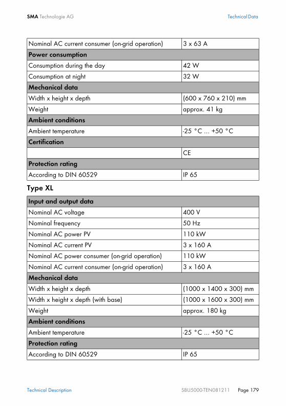
SMA Technologie AG Technical Data
Technical Description SBU5000-TEN081211 Page 179
Type XL
Nominal AC current consumer (on-grid operation) 3 x 63 A
Power consumption
Consumption during the day 42 W
Consumption at night 32 W
Mechanical data
Width x height x depth (600 x 760 x 210) mm
Weight approx. 41 kg
Ambient conditions
Ambient temperature -25 °C ... +50 °C
Certification
CE
Protection rating
According to DIN 60529 IP 65
Input and output data
Nominal AC voltage 400 V
Nominal frequency 50 Hz
Nominal AC power PV 110 kW
Nominal AC current PV 3 x 160 A
Nominal AC power consumer (on-grid operation) 110 kW
Nominal AC current consumer (on-grid operation) 3 x 160 A
Mechanical data
Width x height x depth (1000 x 1400 x 300) mm
Width x height x depth (with base) (1000 x 1600 x 300) mm
Weight approx. 180 kg
Ambient conditions
Ambient temperature -25 °C ... +50 °C
Protection rating
According to DIN 60529 IP 65

Technical Data SMA Technologie AG
Page 180 SBU5000-TEN081211 Technical Description
21.3 Battery Connection Box (SBU-CON.33)
Mechanical data
Width x height x depth (375 x 250 x 150) mm
Width x height x depth (with screw connections) (375 x 350 x 150) mm
Weight approx. 20 kg

SMA Technologie AG Certificates
Technical Description SBU5000-TEN081211 Page 181
22 Certificates

Certificates SMA Technologie AG
Page 182 SBU5000-TEN081211 Technical Description

SMA Technologie AG Contact
Technical Description SBU5000-TEN081211 Page 183
23 ContactIf you have any questions or queries, please contact us. A team of qualified engineersand technicians is at your disposal. Please have the following information at hand whenyou call us:• Inverter type (Sunny Backup 5000, see name plate)• Voltage/frequency type• Serial number (see name plate or parameter "312.03 SN")• Firmware version (see parameter "312.02 FwVer")• Error message shown on the display• Battery type• Nominal battery capacity• Nominal battery voltage• Communication products used• Type and size of additional energy sources (generators, PV systems, PV inverters)• If a generator exists:
- generator type- generator capacity- maximum generator current- generator interface
SMA Technologie AGHannoversche Strasse 1 - 534266 NiestetalGermanyTel. (+49) 561 95 22 - 399 Fax (+49) 561 95 22 - [email protected]
Always use the MMC/SD card to save data and events. This is necessary in orderfor SMA Technologie AG to be able to help you in the event of a fault. To ensurethat you have saved the present error list and event list on the MMC/SD card,write all data to the MMC/SD card with the parameter "440.01 CardFunc" andthe option "ForceWrite".

Glossary SMA Technologie AG
Page 184 SBU5000-TEN081211 Technical Description
24 GlossaryAbsorption phaseConstant V phase: a charging phase using constant charging voltage. The chargingcurrent constantly decreases during this phase.
ACAbbreviation for “Alternating Current”.
AC couplingThe connection of various loads, generators and storage devices on the AC side.
AGM batteryAbsorbent glass mat separator battery. This is a battery where the electrolyte (a mixtureof water and sulfuric acid) is bound to a glass fiber mat, a type of closed lead acidbattery. A gas mixture (hydrogen and oxygen) is always generated when lead acidbatteries are charged, and in normal operation this is internally recombined to formwater. This removes the need for regularly refilling the battery cells with water, which iswhy these batteries are often described as “low maintenance” or even “maintenancefree”. AGM batteries are available from many different manufacturers for a wide rangeof applications. They usually have very good high current properties but are not verycharge-cycle resistant.
AhAbbreviation for "ampere hours": unit of electrical charge, one ampere hour is thecharge provided by a constant current of 1 A over a period of one hour - when twoseparate charges are connected.
Automatic disconnection deviceThe “automatic disconnection device between a grid parallel power-generating systemand the public low voltage grid” is an equivalent replacement for a normal publicdisconnection device with isolation function which is accessible to the distribution gridoperator at any time. This is a mandatory safety device which prevents energy from asolar power system being fed into an external power grid when the external powergenerator is not functioning. In the Sunny Boy / Sunny Mini Central, this function isperformed by the “SMA grid guard Version 2”. In the Sunny Backup 5000, it isintegrated in the Automatic Switch Box.
Automatic Switch BoxSwitching device which switches a Sunny Backup system between grid operation andstand-alone grid operation. In the Sunny Backup system, during grid operation a PVsystem is operated via an automatic disconnection device at its own feed-in counter;upon grid failure, it is switched to the stand-alone grid which is disconnected from thepublic grid. As an option, the box can also integrate a diesel generator into the SunnyBackup system.

SMA Technologie AG Glossary
Technical Description SBU5000-TEN081211 Page 185
Backup systemBackup systems are power supply systems which provide an extra level of security forstandard power supply systems. The public grid is usually the standard power supplysystem, which is backed up by an additional stand-alone grid system in case of a poweroutage. In addition to the backup systems, diesel generators in PV battery systems arealso described as backup generators. Here they perform the same task as a backupsystem for the public grid.
BatteryA battery is an electrochemical storage device which can release previously storedchemical energy as electrical energy. A distinction is made between non-rechargeableprimary elements (often used in (e.g.) consumer markets) and rechargeable secondaryelements (accumulators). In stand-alone grid systems, the batteries used asrechargeable secondary elements are almost exclusively lead acid batteries and, veryrarely, nickel/cadmium batteries.
Battery bankSee Battery system
Battery charging modeA battery inverter operating mode, in which the inverter takes energy from the AC gridto recharge the battery in a controlled fashion. In this operating mode, the batteryinverter is primarily responsible for correctly charging the battery, and acts as anindependent battery charger.
Battery inverterSee Battery power converter
Battery managementThe battery management is responsible for optimal battery charging and reliableprotection against deep discharge. This is the only way of ensuring that the batteryservice life reflects the manufacturer's specifications.
Battery power converterA bidirectional power converter which can regulate voltage and frequency in a stand-alone grid and is also responsible for correct battery charging.
Battery systemSeries connection and possibly also parallel connection of several identical batteries.Battery banks of 12 V, 24 V, 48 V and 60 V are typical.
Boost chargeBoost charge: allows the batteries to be charged to a level of approx. 85 – 90 % inthe shortest time and the most efficient manner.

Glossary SMA Technologie AG
Page 186 SBU5000-TEN081211 Technical Description
Bulk phaseI phase: the charging phase in which charging can be done using the maximumallowable charging current.
CapacityDescribes the storage capability of a cell or battery, specified in Ah (ampere hours).The capacity of a battery is heavily dependent on the charging cycle, the amount ofcurrent drawn and the temperature.
Central inverterAn inverter concept in which all PV modules are connected to each other (in series and/or parallel) and which uses a single inverter for feeding energy into the external grid.The lower cost of the inverter is usually offset by the much higher installation outlayrequired and possible yield losses due to variations in shadowing on individual solarmodules.
Charge levelDescribes the present amount of charge which can be drawn from the battery, inpercent of the nominal capacity (100 % = battery full, 0 % = battery empty).
Charge modeSee Battery charging mode
Charging throughputSee Nominal charging throughput
ClusterSeveral Sunny Island or Sunny Backup inverters which are connected in parallel on theDC side, and which are connected to a shared battery system. On the AC output side,these inverters can also be connected in parallel (single-phase system), or form a multi-phase system. The devices in a cluster must be connected by communication cables,and must be configured in such a manner that one device (-> master) leads the cluster,and all other devices (-> slaves) communicate with the leading device.
C rateThe nominal capacity specification is always provided along with the discharge time onwhich the capacity is based. The nominal capacity is the product of the constantcharging current IN and the discharge time tN, which passes between commencementof discharging the fully charged battery and when the final discharge voltage US isreached. For stationary batteries, the C10 capacity is usually specified, i.e. a batterywith C10 = 200 Ah can be discharged for 10 hours at a nominal current of 0.1 × C10= I10 = 20 A.
DCAbbreviation for “Direct Current”.

SMA Technologie AG Glossary
Technical Description SBU5000-TEN081211 Page 187
DeratingEnglish for "reduction": a controlled reduction in performance, usually dependent oncomponent temperatures. Compared with the (also common) practice of completelyshutting down the device, the effect on the external grid is smaller with derating.
DSPAbbreviation for Digital Signal Processor. A DSP is a microprocessor chip especiallydeveloped for digital signal processing and control.
ElectrolyteAllows the conduction of ions within a battery. In a lead acid battery, the electrolyte isdiluted sulfuric acid and is also a reactant in the electrochemical reaction. Nickel/cadmium batteries use an alkaline electrolyte (potassium hydroxide).
EPROMSee Flash EEPROM
Equalization chargeSee Equalize charge
Equalize chargeEqualization charge: allows multiple series-connected battery cells to be charged to aunified charge level of 95 – 100 %. Without regular equalization charging, the chargestates of the individual cells slowly drift apart, which can lead to premature battery bankfailure.
FirmwareFirmware is software which is embedded in a chip in various electronic devices, suchas hard disk recorders, DVD burners and players, newer television sets, householdappliances and computers - in contrast to software, which is stored on hard drives, CD-ROMs or other media. These days, firmware is usually stored in a flash memory or anEEPROM.
FLAFlooded lead acid battery: a lead acid battery with liquid electrolyte, also oftendescribed as a closed lead acid battery.
Flash EEPROMThe abbreviation EEPROM stands for Electrically Erasable Programmable Read-OnlyMemory. Flash memories are digital storage devices (chips). The exact designation is“flash EEPROM”. In contrast to “normal” EEPROM memories, in flash EEPROM it is notpossible to delete individual bytes (the smallest addressable memory units).EEPROM is a non-volatile, electronic memory component used (for example) incomputer technology, and mainly in embedded systems. Flash EEPROMs are used where information must be permanently stored in the smallestamount of space, e.g. for storing the firmware.

Glossary SMA Technologie AG
Page 188 SBU5000-TEN081211 Technical Description
Float chargeMaintenance charge: allows the batteries to be slowly charged to a charge level of100 % without the negative effects of overcharging. Complete charging to 100 % usingfloat charge takes several days. For this reason, float charging is more important forgrid backup systems and less important for stand-alone grids.
Full chargeFull charge: recharging of the batteries to a level of approx. 95 % on a regular basis(at least once a month). This efficiently avoids premature battery aging caused byinadequate charging.
Gel batteryA type of battery in which the electrolyte (a mixture of water and sulfuric acid) is boundinto a gel. This is a type of so-called closed lead acid battery. A gas mixture (hydrogenand oxygen) is always generated when lead acid batteries are charged, and in normaloperation this is internally recombined to form water. This removes the need forregularly refilling the battery cells with water, which is why these batteries are oftendescribed as “low maintenance” or even “maintenance free” (see also AGM battery).Gel batteries are available from many different manufacturers for a wide range ofapplications. There are gel batteries for high-current applications but also for cycleoperation with very high cycle resistance.
GeneratorAn electrical generator is an electrical machine which converts kinetic or mechanicalenergy into electrical energy. Here, not only the electrical generator itself, but also thecombustion unit (diesel, petrol, or gas motor) necessary for the power unit is combinedtogether with the electrical generator and simplified under the term “generator”. This isalso described colloquially as a power generator.
Grid-connected systemPV system which is connected to the power supply grid of an external energy supplier.
InverterA device for converting the direct current (DC) from the PV generator into alternatingcurrent (AC), which is necessary for connection of most normal household devices andespecially for feeding solar energy into an existing supply grid. Inverters for PV systemsusually include at least one MPP tracker, store operating data, and monitor the gridconnection of the PV system (see also MSD).
Inverter modeOperating mode of a battery inverter where it supplies the stand-alone grid from thebattery energy. In this operating mode, the battery inverter is especially responsible forthe control of frequency and voltage in the stand-alone grid.

SMA Technologie AG Glossary
Technical Description SBU5000-TEN081211 Page 189
Main clusterThe leading cluster in a multicluster system. The main cluster, for example, has the tasksof voltage and frequency regulation, grid monitoring, generator control, loadmanagement, and control of the Automatic Switch Box in a backup system.
Maintenance chargeSee Float charge
MasterA configuration setting which assigns the leading role in a cluster to a Sunny Island orSunny Backup inverter. This stipulates that centralized control and monitoring tasks,which in a cluster must be performed by just one device (e.g., frequency regulation,battery management, generator control, and control of the Automatic Switch Box in theSunny Backup system) are to be performed by this device. All other inverters of thecluster must be configured so as to leave these tasks to the master, and to be led by themaster (-> slaves). The master is also the device at which the cluster's configuration,operation, and data recording occurs in a centralized manner.
Maximum Power Point “MPP“The operating point (defined current/voltage curve) of a PV generator where themaximum power can be drawn. The actual MMP changes constantly depending, forexample, on the level of solar irradiation and the ambient temperature.
MPP trackerRegulation of the power drawn so that a PV generator is operated for as long aspossible at the MPP. This operating point varies with the solar irradiation andtemperature conditions of the modules. MPP tracking optimizes the extraction ofelectrical power and is a feature of inverters and charge controllers.
MSDSee Automatic disconnection device
Multicluster systemParallel connection of several clusters on the AC output side in a stand-alone grid orbackup system. The master devices of the individual clusters must be connected bycommunication cables, and configured in such a manner that one cluster leads theentire system (see main cluster) and the master devices of all other clusters (see sub-cluster) communicate with the master of the main cluster.
Multi-string inverterAn inverter which to a great extent combines the advantages of several string inverters(separate MPP tracking of individual strings) and a central inverter (low performance-specific costs).

Glossary SMA Technologie AG
Page 190 SBU5000-TEN081211 Technical Description
NiCdNickel/cadmium battery, contains nickel, cadmium, and potassium hydroxide as theelectrolyte. These require a significantly higher charging voltage, have a lower level ofefficiency and are significantly more expensive than lead acid batteries. However, theirrobustness, cycle resistance and low-temperature capabilities mean that they are usedin certain special applications.
NLMAbbreviation for Powerline modem: communication between SMA inverters and themonitoring devices can be made with a cable, a radio link, or a Powerline modem.Powerline modems use a carrier frequency of approx. 132 kHz modulated onto the ACcables, and data is transferred using FSK (Frequency Shift Keying) of this carrier signal.Details on the Powerline modem can be found (e.g.) in the technical description of theSMA-NLM.
Nominal charging throughputThe charging throughput is the cumulative total discharge current over time, measuredin ampere hours (Ah). These meters are not automatically reset after charging. Thenominal charging throughput is the charging throughput with regard to the nominalcapacity of the batteries.
Overload capabilityThe overload capability of an inverter describes its ability to supply short-term (secondsor minutes) excessive loads that can be significantly higher than the nominal capacityof battery inverters. The overload capability is important to allow startup of electricalmachines which have a nominal power output close to the nominal power output of thestand-alone grid inverter, since these machines typically require six times the nominalcurrent when starting.
Parallel connectionParallel connection of batteries (all positive poles together and all negative polestogether) increases the capacity of the battery bank while keeping the voltage constant.Example: two 24 V/100 Ah batteries connected in parallel still have a voltage of 24V, but have a capacity of 100 Ah + 100 Ah = 200 Ah.
PhotovoltaicsSee PV
Piggy-Back (board)A printed circuit board which is plugged into another board to increase performanceor expand capabilities. A piggy-back board can also replace an individual chip. In thiscase, the chip is removed and the board is plugged into the empty socket.

SMA Technologie AG Glossary
Technical Description SBU5000-TEN081211 Page 191
PLCAbbreviation for Power Line Communication: describes the process of data transferover the grid supply cables. The PLC power module is used to amplify the signal and isconnected in Multi-String and Sunny Mini Central inverters.
PVPhotovoltaics (PV) is the conversion of solar irradiation into electrical energy usingspecial semiconductors, so-called solar cells.
PV generatorTechnical device for the conversion of solar energy into electrical energy. This termencompasses all the electrically connected (in series and in parallel) solar modules ina PV system.
PV moduleSee Solar module
PV systemDescribes a solar power system for generating electrical power. This includes thecomplete collection of components needed for the acquisition and utilization of solarenergy. As well as the PV generator, this also includes the Sunny Boy or Sunny MiniCentral inverter, for example, in the case of grid-connected systems.
Self dischargeCapacitance loss of a battery cell while it is stored or not used. A higher ambienttemperature has a strong influence on self discharge.
Series connectionIn this case the positive pole of each battery is connected to the negative pole of thenext battery. There is only one circuit where current can flow. Series connectionincreases the voltage of the entire battery bank. If two 24 V batteries with a capacityof 100 Ah each are connected in series, the total voltage is 24 V + 24 V = 48 V, whilethe total capacity remains at 100 Ah.
SlaveA configuration setting which assigns a subordinate role in a cluster to a Sunny Islandor Sunny Backup inverter. Thus, this device is relieved of control tasks and monitoringtasks, which must (or may) only be performed by one device in a cluster (-> master).Slave devices accept the configuration settings, present firmware, and start/stopcommands from the master, and report these events, as well as warnings and errormessages.
SOCState of Charge: the charge level of the batteries, see Charge level. If, for example, 25Ah are taken from a 100-Ah battery, the charge level (SOC) is then 75 %.

Glossary SMA Technologie AG
Page 192 SBU5000-TEN081211 Technical Description
SOHState of Health: describes the relationship between the present capacity and thebattery's nominal value, given as a percentage.
Solar cellAn electronic component which generates electrical energy when irradiated withsunlight. Since the voltage produced by a solar cell is very small (approx. 0.5 V),several solar cells are combined to form a solar module. The most commonsemiconductor material presently used for solar cells is silicon, which is manufacturedin different forms (monocrystalline, polycrystalline, amorphous). In addition to vastlydifferent mechanical variations, which are usually designed to increase the level ofefficiency, completely new materials are currently being tested (cadmium telluride,cadmium indium sulphide, titanium dioxide and many others).
Solar energy“Sun energy”, this means energy from sunlight or other solar radiation (heat and/or UVradiation).
Solar moduleElectrical connection of several solar cells encapsulated in a housing to protect thesensitive cells from mechanical stress and environmental influences.
Stand-alone grid systemAn energy generation system which is completely independent of any external powersources.
StringDescribes a group of solar modules electrically connected in series. A PV system usuallyconsists of a number of strings, which avoids excessive yield losses caused by variationsin shadowing on different modules.
String inverterAn inverter concept which avoids the disadvantages of the central inverter concept. ThePV generator is split into individual strings, each of which is connected to the externalgrid by means of its own string inverter. This greatly simplifies installation and reducesthe yield losses which can be caused by manufacturing deviations or variations inshadowing on the solar modules.
Sub-clusterCluster in a multicluster system which is subordinate to a main cluster, and thus does notlead the entire system.
VRLAValve regulated lead acid battery: lead-acid battery with semi-solid electrolyte orclosed lead acid battery. Examples of this type of battery are gel batteries and AGMbatteries (Absorbent Glass Mat).

Legal Restrictions SMA Technologie AG
Page 193 SBU5000-TEN081211 Technical Description
The information contained in this document is the property of SMA Technologie AG. Publishing its content,either partially or in full, requires the written permision of SMA Technologie AG. Any internal companycopying of the document for the purposes of evaluating the product or its correct implementation is allowedand does not require permission.
Exclusion of liabilityThe general terms and conditions of delivery of SMA Technologie AG shall apply.The content of these documents is continually checked and amended, where necessary. However,discrepancies cannot be excluded. No guarantee is made for the completeness of these documents. The latestversion is available on the Internet at www.SMA.de or from the usual sales channels.Guarantee or liability claims for damages of any kind are exlcuded if they are caused by one or more of thefollowing:• Improper or inappropriate use of the product• Operating the product in an unintended environment• Operating the product whilst ignoring relevant, statutory safety regulations in the deployment location• Ignoring safety warnings and instructions contained in all documents relevant to the product• Operating the product under incorrect safety or protection conditions• Altering the product or supplied software without authority• The product malfunctions due to operating attached or neighboring devices beyond statutory limit values• In case of unforeseen calamity or force majeure
Software licensingThe use of supplied software produced by SMA Technologie AG is subject to the following conditions:This software may be copied for internal company purposes and may be installed on any number ofcomputers. Supplied source codes may be changed or adapted for internal company purposes on your ownresponsibility. Drivers may also be transferred to other operating systems. Source codes may only be publishedwith the written permission of SMA Technologie AG. Sub-licensing of software is not permissible.Limitation of liability: SMA Technologie AG rejects any liability for direct or indirect damages arising from theuse of software developed by SMA Technologie AG. This also applies to the provision or non-provision ofsupport activities.Supplied software not developed by SMA Technologie AG is subject to the respective licensing and liabilityagreements of the manufacturer.
TrademarksAll trademarks are recognized even if these are not marked separately. Missing designations do not mean thata product or brand is not a registered trademark. SMA Technologie AGHannoversche Straße 1-534266 NiestetalGermanyTel. +49 561 9522-0Fax +49 561 9522-100www.SMA.deE-mail: [email protected]© 2004 — 2007 SMA Technologie AG. All rights reserved.


www.SMA.deSales Solar Technology
SMA Technologie AGHannoversche Strasse 1–534266 Niestetal, GermanyTel. : +49 561 9522 4000Fax: +49 561 9522 4040E-mail: [email protected]: +800 SUNNYBOYFreecall: +800 78669269
Innovation in Systems Technology for the Success of Photovoltaics