Embed Size (px)
Citation preview
Problem:
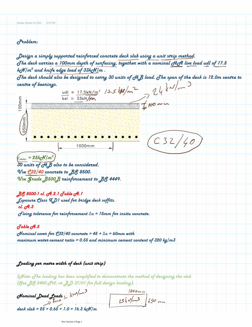
Design a simply supported reinforced concrete deck slab using a unit strip method. The deck carries a 100mm depth of surfacing, together with a nominal HA live load udl of 17.5 kN/m2 and knife edge load of 33kN/m . The deck should also be designed to carry 30 units of HB load. The span of the deck is 12.0m centre to centre of bearings.
γconc. = 25kN/m3
30 units of HB also to be considered.Use C32/40 concrete to BS 8500.Use Grade B500B reinforcement to BS 4449.
BS 8500-1 cl. A.2.1 Table A.1Exposure Class XD1 used for bridge deck soffits.cl. A.3Fixing tolerence for reinforcement Δc = 15mm for insitu concrete.
Table A.5Nominal cover for C32/40 concrete = 45 + Δc = 60mm with maximum water-cement ratio = 0.55 and minimum cement content of 320 kg/m3
Loading per metre width of deck (unit strip)
(Note: The loading has been simplified to demonstrate the method of designing the slab (See BS 5400 Pt2, or BD 37/01 for full design loading).
Nominal Dead Loads :
deck slab = 25 × 0.65 × 1.0 = 16.3 kN/m
Sunday, October 25, 2015 11:57 PM
New Section 4 Page 1
Nominal Dead Loads :
deck slab = 25 × 0.65 × 1.0 = 16.3 kN/m
surfacing = 24 × 0.1 × 1.0 = 2.4 kN/m
Nominal Live Load :
HA = 17.5 × 1.0 + 33.0 = 17.5 kN/m(udl) + 33kN(kel)
30 units HB = 30 × 10 / 4 per wheel = 75 kN per wheel
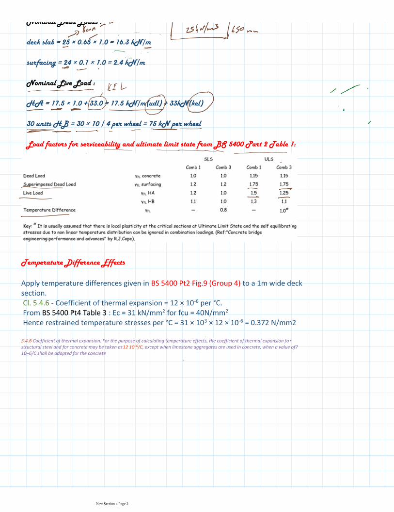
Load factors for serviceability and ultimate limit state from BS 5400 Part 2 Table 1:
Temperature Difference Effects
Apply temperature differences given in BS 5400 Pt2 Fig.9 (Group 4) to a 1m wide deck section.Cl. 5.4.6 - Coefficient of thermal expansion = 12 × 10-6 per °C.From BS 5400 Pt4 Table 3 : Ec = 31 kN/mm2 for fcu = 40N/mm2
Hence restrained temperature stresses per °C = 31 × 103 × 12 × 10-6 = 0.372 N/mm2
5.4.6 Coefficient of thermal expansion. For the purpose of calculating temperature effects, the coefficient of thermal expansion fo r structural steel and for concrete may be taken as12 10–6/C, except when limestone aggregates are used in concrete, when a value of7 10–6/C shall be adopted for the concrete
New Section 4 Page 2
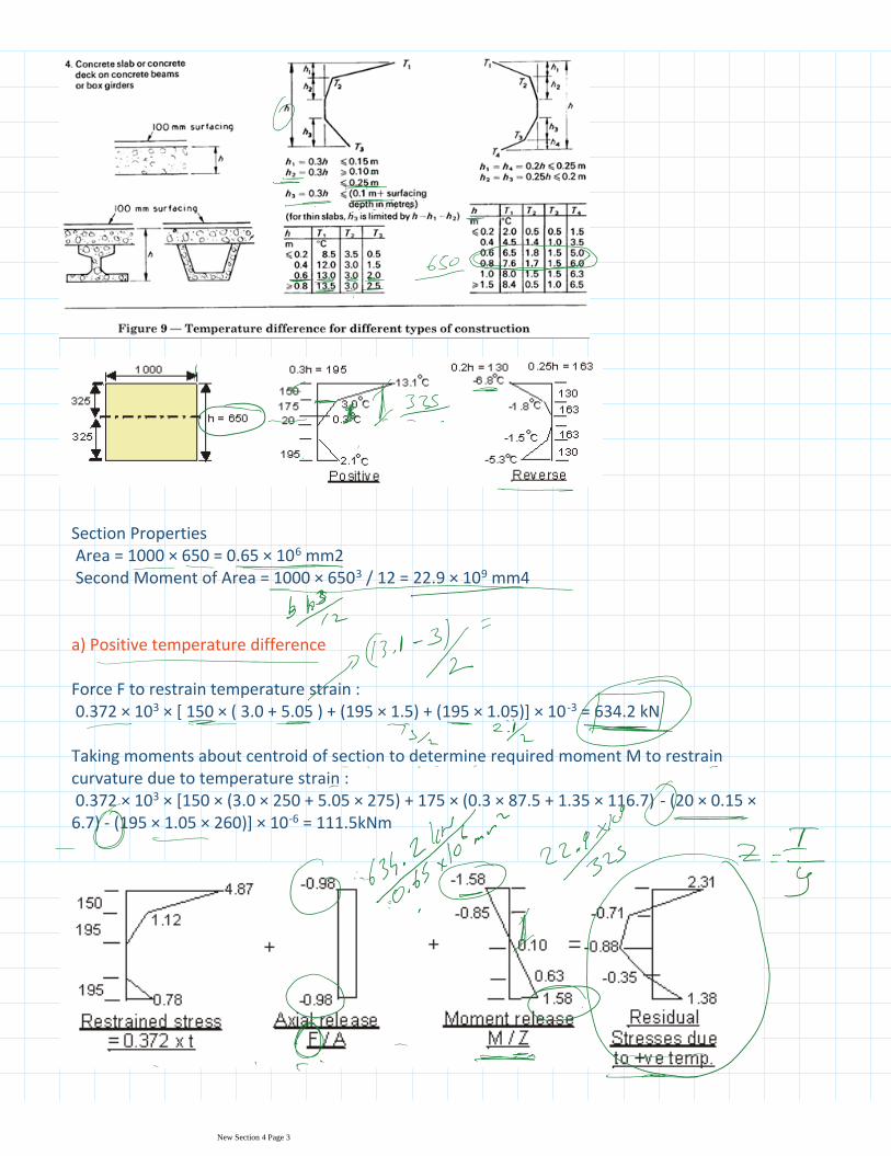
Section PropertiesArea = 1000 × 650 = 0.65 × 106 mm2Second Moment of Area = 1000 × 6503 / 12 = 22.9 × 109 mm4
a) Positive temperature difference
Force F to restrain temperature strain :0.372 × 10³ × [ 150 × ( 3.0 + 5.05 ) + (195 × 1.5) + (195 × 1.05)] × 10 -3 = 634.2 kN
Taking moments about centroid of section to determine required moment M to restrain curvature due to temperature strain :0.372 × 103 × [150 × (3.0 × 250 + 5.05 × 275) + 175 × (0.3 × 87.5 + 1.35 × 116.7) - (20 × 0.15 × 6.7) - (195 × 1.05 × 260)] × 10-6 = 111.5kNm
b) Reverse temperature difference
New Section 4 Page 3
b) Reverse temperature difference
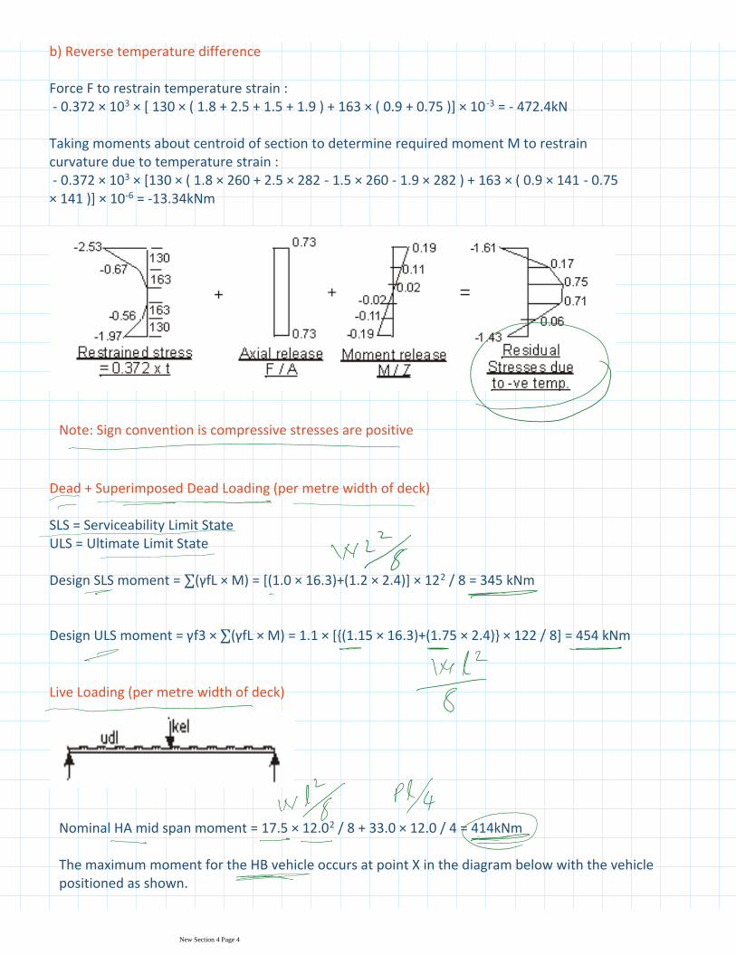
Force F to restrain temperature strain :- 0.372 × 10³ × [ 130 × ( 1.8 + 2.5 + 1.5 + 1.9 ) + 163 × ( 0.9 + 0.75 )] × 10 -3 = - 472.4kN
Taking moments about centroid of section to determine required moment M to restrain curvature due to temperature strain :- 0.372 × 103 × [130 × ( 1.8 × 260 + 2.5 × 282 - 1.5 × 260 - 1.9 × 282 ) + 163 × ( 0.9 × 141 - 0.75 × 141 )] × 10-6 = -13.34kNm
Note: Sign convention is compressive stresses are positive
Dead + Superimposed Dead Loading (per metre width of deck)
SLS = Serviceability Limit StateULS = Ultimate Limit State
Design SLS moment = ∑(γfL × M) = [(1.0 × 16.3)+(1.2 × 2.4)] × 122 / 8 = 345 kNm
Design ULS moment = γf3 × ∑(γfL × M) = 1.1 × [{(1.15 × 16.3)+(1.75 × 2.4)} × 122 / 8] = 454 kNm
Live Loading (per metre width of deck)
Nominal HA mid span moment = 17.5 × 12.02 / 8 + 33.0 × 12.0 / 4 = 414kNm
The maximum moment for the HB vehicle occurs at point X in the diagram below with the vehicle positioned as shown.
New Section 4 Page 4
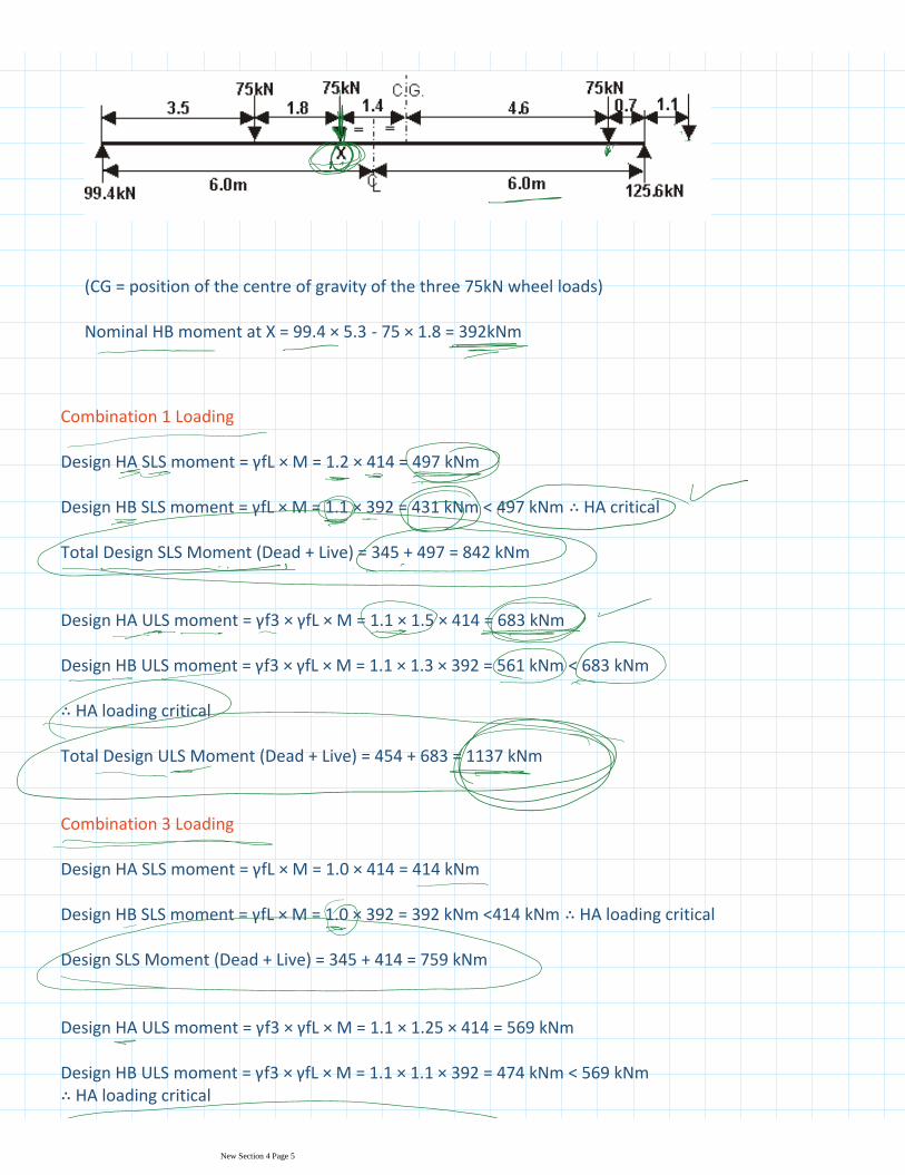
(CG = position of the centre of gravity of the three 75kN wheel loads)
Nominal HB moment at X = 99.4 × 5.3 - 75 × 1.8 = 392kNm
Combination 1 Loading
Design HA SLS moment = γfL × M = 1.2 × 414 = 497 kNm
Design HB SLS moment = γfL × M = 1.1 × 392 = 431 kNm < 497 kNm ∴ HA critical
Total Design SLS Moment (Dead + Live) = 345 + 497 = 842 kNm
Design HA ULS moment = γf3 × γfL × M = 1.1 × 1.5 × 414 = 683 kNm
Design HB ULS moment = γf3 × γfL × M = 1.1 × 1.3 × 392 = 561 kNm < 683 kNm
∴ HA loading critical
Total Design ULS Moment (Dead + Live) = 454 + 683 = 1137 kNm
Combination 3 Loading
Design HA SLS moment = γfL × M = 1.0 × 414 = 414 kNm
Design HB SLS moment = γfL × M = 1.0 × 392 = 392 kNm <414 kNm ∴ HA loading critical
Design SLS Moment (Dead + Live) = 345 + 414 = 759 kNm
Design HA ULS moment = γf3 × γfL × M = 1.1 × 1.25 × 414 = 569 kNm
Design HB ULS moment = γf3 × γfL × M = 1.1 × 1.1 × 392 = 474 kNm < 569 kNm ∴ HA loading critical
New Section 4 Page 5
Design HB ULS moment = γf3 × γfL × M = 1.1 × 1.1 × 392 = 474 kNm < 569 kNm ∴ HA loading critical
Design ULS Moment (Dead + Live) = 454 + 569 = 1023 kNm
Ultimate Capacity of Deck Slab
Ultimate Design Moment = 1137 kNm
BS 5400 Pt 4 cl. 5.1.2.1
It is usual to design reinforced concrete for the ultimate limit state and check for serviceability conditions.cl. 5.4.2
Use clause 5.3.2 for the resistance moments in slabs.
cl. 5.3.2.3
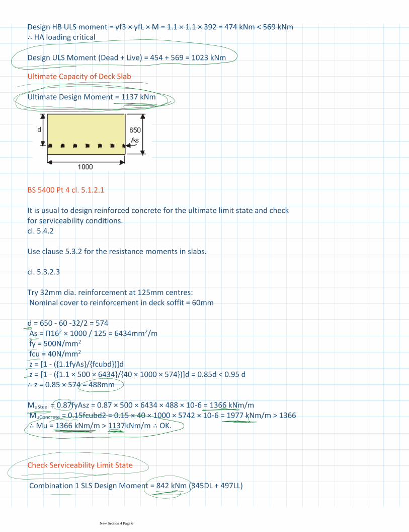
Try 32mm dia. reinforcement at 125mm centres:Nominal cover to reinforcement in deck soffit = 60mm
d = 650 - 60 -32/2 = 574As = Π162 × 1000 / 125 = 6434mm2/mfy = 500N/mm2
fcu = 40N/mm2
z = [1 - ({1.1fyAs}/{fcubd})]dz = [1 - ({1.1 × 500 × 6434}/{40 × 1000 × 574})]d = 0.85d < 0.95 d ∴ z = 0.85 × 574 = 488mm
MuSteel = 0.87fyAsz = 0.87 × 500 × 6434 × 488 × 10-6 = 1366 kNm/mMuConcrete = 0.15fcubd2 = 0.15 × 40 × 1000 × 5742 × 10-6 = 1977 kNm/m > 1366 ∴ Mu = 1366 kNm/m > 1137kNm/m ∴ OK.
Check Serviceability Limit State
Combination 1 SLS Design Moment = 842 kNm (345DL + 497LL)
Determine depth 'X' to neutral axis of cracked section:
New Section 4 Page 6
Determine depth 'X' to neutral axis of cracked section:
cl. 4.3.2.1 Table 3
Youngs Modulus for concrete for short term loading = Ec = 31 kN/mm2
cl. 4.3.2.2
Youngs Modulus for steel reinforcement = Es = 200 kN/mm2
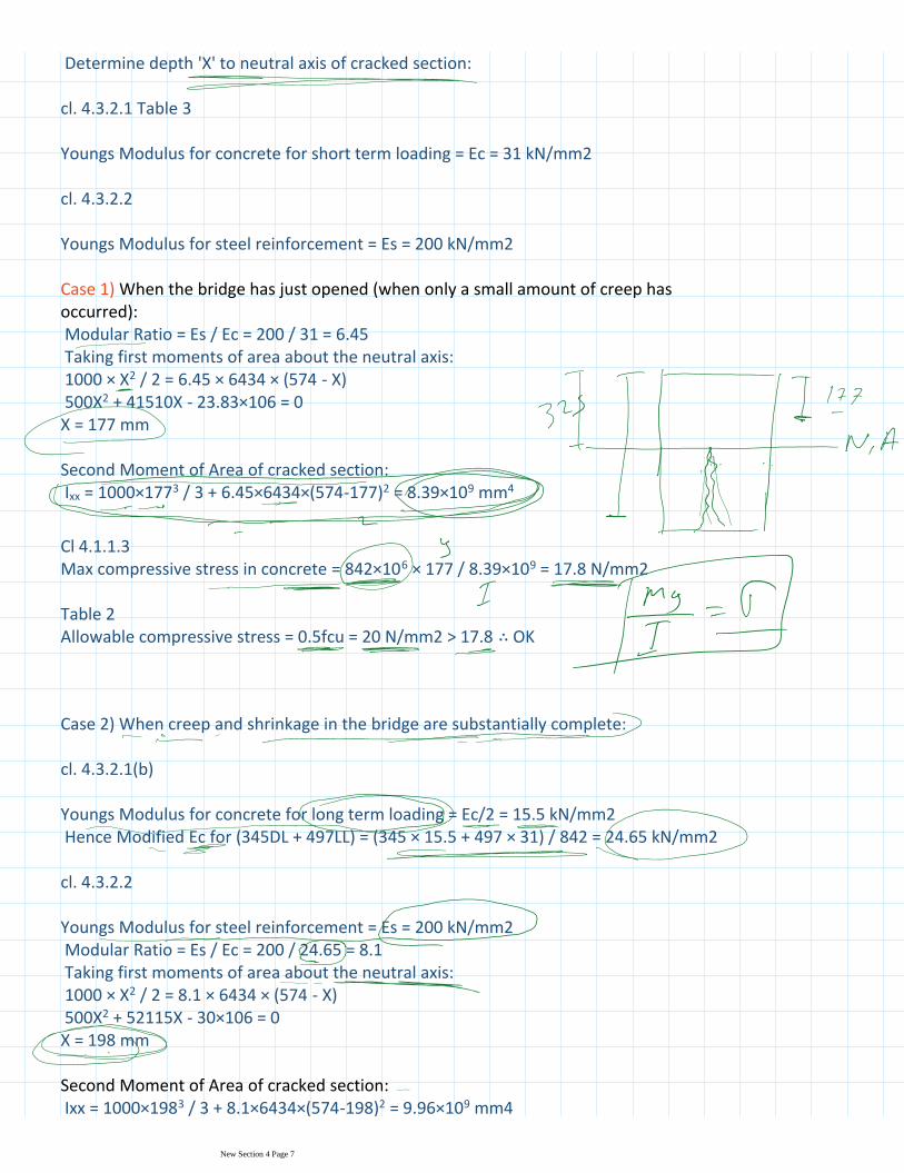
Case 1) When the bridge has just opened (when only a small amount of creep has occurred):Modular Ratio = Es / Ec = 200 / 31 = 6.45Taking first moments of area about the neutral axis:1000 × X2 / 2 = 6.45 × 6434 × (574 - X)500X2 + 41510X - 23.83×106 = 0X = 177 mm
Second Moment of Area of cracked section:Ixx = 1000×1773 / 3 + 6.45×6434×(574-177)2 = 8.39×109 mm4
Cl 4.1.1.3Max compressive stress in concrete = 842×106 × 177 / 8.39×109 = 17.8 N/mm2
Table 2Allowable compressive stress = 0.5fcu = 20 N/mm2 > 17.8 ∴ OK
Case 2) When creep and shrinkage in the bridge are substantially complete:
cl. 4.3.2.1(b)
Youngs Modulus for concrete for long term loading = Ec/2 = 15.5 kN/mm2Hence Modified Ec for (345DL + 497LL) = (345 × 15.5 + 497 × 31) / 842 = 24.65 kN/mm2
cl. 4.3.2.2
Youngs Modulus for steel reinforcement = Es = 200 kN/mm2Modular Ratio = Es / Ec = 200 / 24.65 = 8.1Taking first moments of area about the neutral axis:1000 × X2 / 2 = 8.1 × 6434 × (574 - X)500X2 + 52115X - 30×106 = 0X = 198 mm
Second Moment of Area of cracked section:Ixx = 1000×1983 / 3 + 8.1×6434×(574-198)2 = 9.96×109 mm4
New Section 4 Page 7
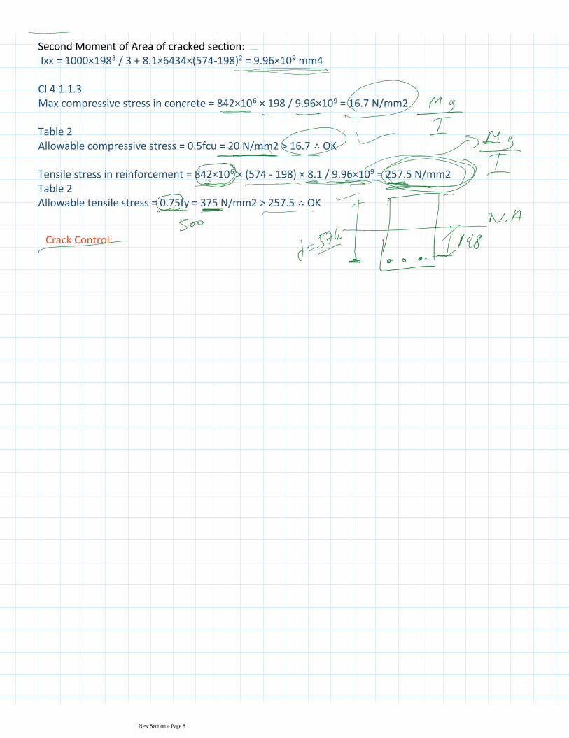
Second Moment of Area of cracked section:Ixx = 1000×1983 / 3 + 8.1×6434×(574-198)2 = 9.96×109 mm4
Cl 4.1.1.3Max compressive stress in concrete = 842×106 × 198 / 9.96×109 = 16.7 N/mm2
Table 2Allowable compressive stress = 0.5fcu = 20 N/mm2 > 16.7 ∴ OK
Tensile stress in reinforcement = 842×106 × (574 - 198) × 8.1 / 9.96×109 = 257.5 N/mm2Table 2Allowable tensile stress = 0.75fy = 375 N/mm2 > 257.5 ∴ OK
Crack Control:
New Section 4 Page 8
![City Research Online · multiplied by the factor of 6. On the other hand, the British Standard BS 5400: Part 2 [19] was the rst design code to deal with vibration serviceability in](https://img.pdfslide.us/doc/110x75/5e6715f0944e564e70651646/city-research-online-multiplied-by-the-factor-of-6-on-the-other-hand-the-british.jpg)