Embed Size (px)
Citation preview
Sun Microsystems, Inc.www.sun.com
Submit comments about this document at: http://www.sun.com/hwdocs/feedback
Sun StorageTek™ 2500 Series ArrayHardware Installation Guide
Part No. 820-0015-10March 2007

PleaseRecycle
Copyright 2007 Sun Microsystems, Inc., 4150 Network Circle, Santa Clara, California 95054, U.S.A. All rights reserved.
Sun Microsystems, Inc. has intellectual property rights relating to technology that is described in this document. In particular, and withoutlimitation, these intellectual property rights may include one or more of the U.S. patents listed at http://www.sun.com/patents and one ormore additional patents or pending patent applications in the U.S. and in other countries.
This document and the product to which it pertains are distributed under licenses restricting their use, copying, distribution, anddecompilation. No part of the product or of this document may be reproduced in any form by any means without prior written authorization ofSun and its licensors, if any.
Third-party software, including font technology, is copyrighted and licensed from Sun suppliers.
Parts of the product may be derived from Berkeley BSD systems, licensed from the University of California. UNIX is a registered trademark inthe U.S. and in other countries, exclusively licensed through X/Open Company, Ltd.
Sun, Sun Microsystems, the Sun logo, Java, AnswerBook2, docs.sun.com, Sun Fire, Sun StoragEdge, Sun StorageTek, and Solaris aretrademarks or registered trademarks of Sun Microsystems, Inc. in the U.S. and in other countries.
All SPARC trademarks are used under license and are trademarks or registered trademarks of SPARC International, Inc. in the U.S. and in othercountries. Products bearing SPARC trademarks are based upon an architecture developed by Sun Microsystems, Inc.
The OPEN LOOK and Sun™ Graphical User Interface was developed by Sun Microsystems, Inc. for its users and licensees. Sun acknowledgesthe pioneering efforts of Xerox in researching and developing the concept of visual or graphical user interfaces for the computer industry. Sunholds a non-exclusive license from Xerox to the Xerox Graphical User Interface, which license also covers Sun’s licensees who implement OPENLOOK GUIs and otherwise comply with Sun’s written license agreements.
U.S. Government Rights—Commercial use. Government users are subject to the Sun Microsystems, Inc. standard license agreement andapplicable provisions of the FAR and its supplements.
DOCUMENTATION IS PROVIDED "AS IS" AND ALL EXPRESS OR IMPLIED CONDITIONS, REPRESENTATIONS AND WARRANTIES,INCLUDING ANY IMPLIED WARRANTY OF MERCHANTABILITY, FITNESS FOR A PARTICULAR PURPOSE OR NON-INFRINGEMENT,ARE DISCLAIMED, EXCEPT TO THE EXTENT THAT SUCH DISCLAIMERS ARE HELD TO BE LEGALLY INVALID.
Copyright 2007 Sun Microsystems, Inc., 4150 Network Circle, Santa Clara, Californie 95054, États-Unis. Tous droits réservés.
Sun Microsystems, Inc. possède les droits de propriété intellectuels relatifs à la technologie décrite dans ce document. En particulier, et sanslimitation, ces droits de propriété intellectuels peuvent inclure un ou plusieurs des brevets américains listés sur le sitehttp://www.sun.com/patents, un ou les plusieurs brevets supplémentaires ainsi que les demandes de brevet en attente aux les États-Unis etdans d’autres pays.
Ce document et le produit auquel il se rapporte sont protégés par un copyright et distribués sous licences, celles-ci en restreignent l’utilisation,la copie, la distribution, et la décompilation. Aucune partie de ce produit ou document ne peut être reproduite sous aucune forme, par quelquemoyen que ce soit, sans l’autorisation préalable et écrite de Sun et de ses bailleurs de licence, s’il y en a.
Tout logiciel tiers, sa technologie relative aux polices de caractères, comprise, est protégé par un copyright et licencié par des fournisseurs deSun.
Des parties de ce produit peuvent dériver des systèmes Berkeley BSD licenciés par l’Université de Californie. UNIX est une marque déposéeaux États-Unis et dans d’autres pays, licenciée exclusivement par X/Open Company, Ltd.
Sun, Sun Microsystems, le logo Sun, Java, AnswerBook2, docs.sun.com, Sun Fire, Sun StoragEdge, Sun StorageTek, et Solaris sont des marquesde fabrique ou des marques déposées de Sun Microsystems, Inc. aux États-Unis et dans d’autres pays.
Toutes les marques SPARC sont utilisées sous licence et sont des marques de fabrique ou des marques déposées de SPARC International, Inc.aux États-Unis et dans d’autres pays. Les produits portant les marques SPARC sont basés sur une architecture développée par SunMicrosystems, Inc.
L’interface utilisateur graphique OPEN LOOK et Sun™ a été développée par Sun Microsystems, Inc. pour ses utilisateurs et licenciés. Sunreconnaît les efforts de pionniers de Xerox dans la recherche et le développement du concept des interfaces utilisateur visuelles ou graphiquespour l’industrie informatique. Sun détient une license non exclusive de Xerox sur l’interface utilisateur graphique Xerox, cette licence couvrantégalement les licenciés de Sun implémentant les interfaces utilisateur graphiques OPEN LOOK et se conforment en outre aux licences écrites deSun.
LA DOCUMENTATION EST FOURNIE "EN L’ÉTAT" ET TOUTES AUTRES CONDITIONS, DÉCLARATIONS ET GARANTIES EXPRESSESOU TACITES SONT FORMELLEMENT EXCLUES DANS LA LIMITE DE LA LOI APPLICABLE, Y COMPRIS NOTAMMENT TOUTEGARANTIE IMPLICITE RELATIVE À LA QUALITÉ MARCHANDE, À L’APTITUDE À UNE UTILISATION PARTICULIÈRE OU ÀL’ABSENCE DE CONTREFAÇON.
Contents
Preface xiii
1. Tray Overviews 1
Front-Access Components of the Trays 2
LEDs on the Front of the Trays 3
Rear-Access Components of the Trays 5
Controllers 6
Sun StorageTek 2540 Array 6
SFP Transceivers 7
Sun StorageTek 2530 Array 8
Controller Tray and Drive Expansion Tray Power-Fan Assembly 9
Sun StorageTek 2501 Array 10
Drive Expansion Tray IOM 10
Drive Expansion Tray IOM Connectors 10
LEDs on the Rear of the Trays 11
Controller LEDs on the Sun StorageTek 2540 Array 11
Controller LEDs on the Sun StorageTek 2530 Array 12
Controller Tray and Drive Expansion Tray Power-Fan Assembly LEDs 13
IOM LEDs on the Sun StorageTek 2501 Array 15
Disk Drives 16
iii
LEDs on the Disk Drives 18
Common Array Manager Software 19
Service Advisor and Customer-Replaceable Units 19
Overview of the Installation Process 20
2. Installing Trays 23
Preparing for the Installation 24
Preparing the Universal Rail Kit 24
Unpacking the Universal Rail Kit 24
Loosening the Rail Adjustment Screws 24
Preparing the Tray 25
Preparing the Cabinet 26
Planning the Order of the Tray Installation 26
Attaching the Rails to a Cabinet 27
Attaching the Universal Rail Kit to a Standard Sun or 19-Inch Cabinet WithThreaded Cabinet Rails 27
Attaching the Universal Rail Kit to a Standard19-Inch Cabinet With Unthreaded Cabinet Rails 31
Installing a Tray in a Cabinet 37
Connecting the Power Cables 42
Intertray Cabling 42
Array Configuration Naming Convention 43
Connecting Expansion Trays 44
Cabling an Expansion Tray to a Controller Tray 45
Cabling an Expansion Tray to Another Expansion Tray 45
Drive Module Cable Labeling 47
Example Label Abbreviation 47
Simplex Configurations 47
Next Steps 48
iv Sun StorageTek 2500 Series Array Hardware Installation Guide • March 2007
3. Connecting the Management Host and Data Hosts 49
Connecting the Management Host 49
Attaching the Ethernet Ports to the LAN of the Management Host 50
Attaching the Ethernet Ports to the Management Host Using an EthernetHub 51
Attaching the Ethernet Ports Directly to the Management Host With a Cross-Over Cable 51
Connecting Data Hosts to the 2540 Array 51
2540 Array Data Host Connection Topologies 52
2540 Array Data Host Connections 54
▼ To Connect Data Hosts Using Fibre Channel 55
Connecting Data Hosts to the 2530 Array 56
▼ To Connect Data Hosts to a 2530 Array 58
Host Cable Labeling 59
Example Label Abbreviation 59
Next Steps 59
4. Powering On the Array 61
Before Powering On 61
Powering On the Array 62
Powering Off the Array 63
Next Steps 64
5. Data Hosts, HBAs, and Other Software 65
Data Host Software 65
HBAs and Drivers 65
Multipathing 66
Setting Up a Data Host On a Solaris System 66
▼ To Obtain Sun Solaris 8 and 9 Data Host Software 67
▼ To Install the SAN 4.4 Data Host Software 67
Contents v
▼ To Obtain Traffic Manager for Operating Systems Other Than Solaris 68
Installing Data Host Software for Operating Systems Other Than Solaris 69
About Data Host Software For Non-Solaris Platforms 69
Downloading and Installing Sun RDAC Software 69
Enabling Multipathing Software 70
▼ Enabling Multipathing Software for Solaris 8 or 9 OS 70
▼ Enabling Multipathing Software for Solaris 10 OS 71
Next Steps 71
6. Configuring IP Addressing 73
About IP Addressing 73
Configuring the IP Address of the Array Controllers 74
Configuring Dynamic (DHCP) IP Addressing 74
Configuring Static IP Addressing 75
Using the Serial Port Interface to Assign IP Addresses 75
▼ To Connect a Terminal to the Serial Port 75
▼ To Set Up the Terminal Emulation Program 76
▼ To Establish a Connection With the Serial Port 77
▼ To Configure the IP Addresses 78
A. Configuring a DHCP Server 81
Before You Begin 81
Setting Up a Solaris DHCP Server 81
Setting Up a Windows 2000 Advanced Server 86
Installing the DHCP Server 87
Configuring the DHCP Server 87
B. Using DC Power 91
DC Power Overview 91
Installation Notes for DC Power 92
vi Sun StorageTek 2500 Series Array Hardware Installation Guide • March 2007

Ship Kit Changes 93
DC Power LEDS 93
Connecting Power Cables 94
▼ Connecting the Cables 95
Turning Off the DC Power During an Emergency 96
Relocation Cautions 96
Glossary 97
Index 107
Contents vii

viii Sun StorageTek 2500 Series Array Hardware Installation Guide • March 2007
Figures
FIGURE 1-1 Sun StorageTek 2500 Series Array Product Overview 2
FIGURE 1-2 Tray Front-Access Components 3
FIGURE 1-3 Location of the LEDs on the Front of the Trays 4
FIGURE 1-4 Controller Tray Rear-Access Components 5
FIGURE 1-5 Drive Expansion Tray Rear-Access Components 6
FIGURE 1-6 Sun StorageTek 2540 Array Connectors 7
FIGURE 1-7 SFP Transceiver for the Sun StorageTek 2540 Array 8
FIGURE 1-8 Sun StorageTek 2530 Array Controller Connectors 9
FIGURE 1-9 SAS Connectors on the Drive Expansion Tray IOM 10
FIGURE 1-10 Locations of the Controller LEDs on the Sun StorageTek 2540 Array 11
FIGURE 1-11 Locations of the Controller LEDs on the Sun StorageTek 2530 Array 12
FIGURE 1-12 Locations of the Power-Fan Assembly LEDs 14
FIGURE 1-13 Locations of the IOM LEDs 15
FIGURE 1-14 Disk Drives 17
FIGURE 1-15 Locations of the Disk Drive LEDs 18
FIGURE 2-1 Loosening the Rail Screws to Adjust the Rail Length 25
FIGURE 2-2 Positioning the Front of the Left Rail Behind the Left Front Cabinet Rail 28
FIGURE 2-3 Securing the Left Rail to the Front of the Cabinet 29
FIGURE 2-4 Adjusting the Length of the Left Rail at the Back of the Cabinet 30
FIGURE 2-5 Securing the Left Rail to the Back of the Cabinet 31
ix

FIGURE 2-6 Inserting the Cabinet Rail Adapter Plate on the Cabinet Rail 32
FIGURE 2-7 Adapter plate in place on the Cabinet Rail. 33
FIGURE 2-8 Slide the flange of the rail behind the cabinet rail and between that and the hook of the railadapter plat.e, as shown. 34
FIGURE 2-9 Securing the Rail to the Front left of the Cabinet 35
FIGURE 2-10 Adjusting the Length of the Rail at the Back of the Cabinet 36
FIGURE 2-11 Securing the Rail to the Back of the Cabinet 37
FIGURE 2-12 Positioning the Tray in the Cabinet 38
FIGURE 2-13 Array Controller Tray Installed 39
FIGURE 2-14 Rail clip and rear mounting hole on rear of array tray. 40
FIGURE 2-15 Securing the Tray to the Front of a Sun Rack 900/1000 Cabinet 41
FIGURE 2-16 Expansion Ports on the Controller Tray 42
FIGURE 2-17 Expansion Ports on an Expansion Tray 43
FIGURE 2-18 1x2 Array Configuration Cabling Example 45
FIGURE 2-19 1x3 Array Configuration Cabling 46
FIGURE 3-1 Ethernet Ports for Controller A and Controller B 50
FIGURE 3-2 Direct connection from a single data host server 53
FIGURE 3-3 Direct Connection from two data host servers 53
FIGURE 3-4 Data host connection through a Fibre Channel switch 53
FIGURE 3-5 Mixed topology of data hosts connected directly and through FC switches 54
FIGURE 3-6 Connecting the SFP and Fiber-optic Cable to a 2540 Controller 55
FIGURE 3-7 FC host connectors on the 2540 controller. 55
FIGURE 3-8 Direct Connection From a Single Host With Dual HBAs 56
FIGURE 3-9 Direct connections from two data hosts with dual HBAs. 57
FIGURE 3-10 Direct connections from three data hosts with dual HBAs. 57
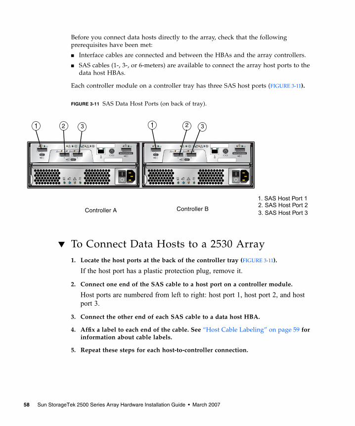
FIGURE 3-11 SAS Data Host Ports (on back of tray). 58
FIGURE 4-1 Tray Power Connectors and Switches 62
FIGURE B-1 Power Fan Assembly Locations. 92
FIGURE B-2 DC Power Connector Cable and Source Wires 92
FIGURE B-3 DC Power Module LEDs, Power Switch, and Power Cable Receptacle. 93
x Sun StorageTek 2500 Series Array Hardware Installation Guide • March 2007
Tables
TABLE 1-1 Description of the LEDs on the Front of the Trays 4
TABLE 1-2 Descriptions of the Controller LEDs on the Sun StorageTek 2540 Array 11
TABLE 1-3 Descriptions of the Controller LEDs on the Sun StorageTek 2530 Array 12
TABLE 1-4 Descriptions of the Power-Fan Assembly LEDs 14
TABLE 1-5 Descriptions of the IOM LEDs 15
TABLE 1-6 Descriptions of the Disk Drive LEDs 18
TABLE 1-7 Disk Drive States Represented by the LEDs 19
TABLE 1-8 Sun StorageTek 2500 Series Array Hardware Installation Checklist 20
TABLE 2-1 Controller and Expansion Tray Configurations 43
TABLE 6-1 RJ45 to DIN Serial Cable Pinouts 76
TABLE B-1 DC Power Module LEDs. 94
xi

xii Sun StorageTek 2500 Series Array Hardware Installation Guide • March 2007
Preface
The Sun StorageTek 2500 Series Array Hardware Installation Guide describes how toinstall rack-mounting rails and array modules on the Sun StorageTek 2500 Seriesarray.
Host management, data host management, and remote command line interface (CLI)functions are performed by the Sun StorageTek Common Array Manager software.For installation and initial configuration of the Sun StorageTek 2500 Series array,including firmware upgrades, initial array setup, partitioning domains, configuringstorage, and configuring IP addressing, see the Sun StorageTek Common ArrayManager Software Installation Guide.
Before You Read This BookBefore you begin to install the Sun StorageTek 2500 Series array, you must havealready prepared the site as described in these books:
■ Sun StorageTek 2500 Series Array Regulatory and Safety Compliance Manual
■ Sun StorageTek 2500 Series Array Site Preparation Guide
xiii
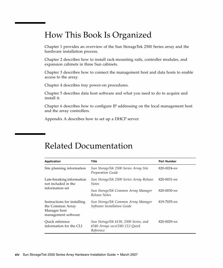
How This Book Is OrganizedChapter 1 provides an overview of the Sun StorageTek 2500 Series array and thehardware installation process.
Chapter 2 describes how to install rack-mounting rails, controller modules, andexpansion cabinets in three Sun cabinets.
Chapter 3 describes how to connect the management host and data hosts to enableaccess to the array.
Chapter 4 describes tray power-on procedures.
Chapter 5 describes data host software and what you need to do to acquire andinstall it.
Chapter 6 describes how to configure IP addressing on the local management hostand the array controllers.
Appendix A describes how to set up a DHCP server.
Related Documentation
Application Title Part Number
Site planning information Sun StorageTek 2500 Series Array SitePreparation Guide
820-0024-nn
Late-breaking informationnot included in theinformation set
Sun StorageTek 2500 Series Array ReleaseNotes
820-0031-nn
Sun StorageTek Common Array ManagerRelease Notes
820-0030-nn
Instructions for installingthe Common ArrayManager hostmanagement software
Sun StorageTek Common Array ManagerSoftware Installation Guide
819-7035-nn
Quick referenceinformation for the CLI
Sun StorageTek 6130, 2500 Series, and6540 Arrays sscs(1M) CLI QuickReference
820-0029-nn
xiv Sun StorageTek 2500 Series Array Hardware Installation Guide • March 2007
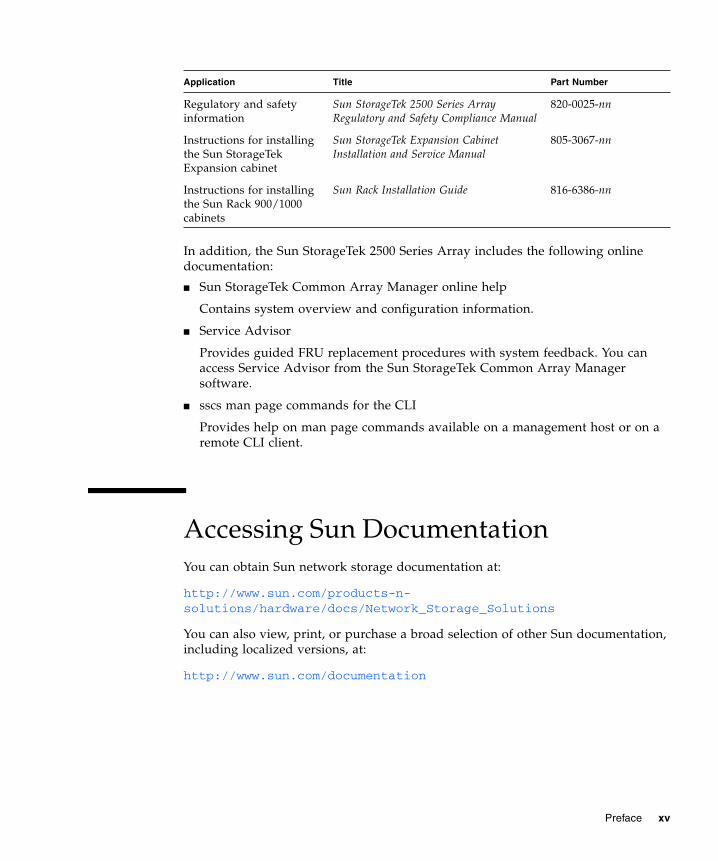
In addition, the Sun StorageTek 2500 Series Array includes the following onlinedocumentation:
■ Sun StorageTek Common Array Manager online help
Contains system overview and configuration information.
■ Service Advisor
Provides guided FRU replacement procedures with system feedback. You canaccess Service Advisor from the Sun StorageTek Common Array Managersoftware.
■ sscs man page commands for the CLI
Provides help on man page commands available on a management host or on aremote CLI client.
Accessing Sun DocumentationYou can obtain Sun network storage documentation at:
http://www.sun.com/products-n-solutions/hardware/docs/Network_Storage_Solutions
You can also view, print, or purchase a broad selection of other Sun documentation,including localized versions, at:
http://www.sun.com/documentation
Regulatory and safetyinformation
Sun StorageTek 2500 Series ArrayRegulatory and Safety Compliance Manual
820-0025-nn
Instructions for installingthe Sun StorageTekExpansion cabinet
Sun StorageTek Expansion CabinetInstallation and Service Manual
805-3067-nn
Instructions for installingthe Sun Rack 900/1000cabinets
Sun Rack Installation Guide 816-6386-nn
Application Title Part Number
Preface xv

Third-Party Web SitesSun is not responsible for the availability of third-party web sites mentioned in thisdocument. Sun does not endorse and is not responsible or liable for any content,advertising, products, or other materials that are available on or through such sitesor resources. Sun will not be responsible or liable for any actual or alleged damageor loss caused by or in connection with the use of or reliance on any such content,goods, or services that are available on or through such sites or resources.
Contacting Sun Technical SupportIf you have technical questions about this product that are not answered in thisdocument, go to:
http://www.sun.com/service/contacting
Sun Welcomes Your CommentsSun is interested in improving its documentation and welcomes your comments andsuggestions. You can submit your comments by going to:
http://www.sun.com/hwdocs/feedback
Please include the title and part number of your document with your feedback:
Sun StorageTek 2500 Series Array Hardware Installation Guide, part number 820-0015-10.
xvi Sun StorageTek 2500 Series Array Hardware Installation Guide • March 2007
CHAPTER 1
Tray Overviews
The Sun StorageTek 2540 Array, the Sun StorageTek 2530 Array, and the SunStorageTek 2501 Array are a family of storage products that provide high-capacity,high-reliability storage in a compact configuration.
The Sun StorageTek 2540 Array is a modular, rackmountable controller tray. It isscalable from a single dual-controller tray (1x1) configuration to a maximumconfiguration of 1x3 with two additional drive expansion trays behind one controllertray.
All three of the trays can be installed in the following cabinets:
■ Sun Rack 900/1000 cabinet
■ Sun StorageTek Expansion cabinet
■ Any 19-inch wide, 4-post, EIA-compatible rack or cabinet with a front-to-backdepth between vertical cabinet rails of 61 cm to 91 cm (24 in. to 36 in.). Thecabinet can have threaded or unthreaded cabinet rails.
The Sun StorageTek 2540 Array and the Sun StorageTek 2530 Array contain diskdrives for storing data and controllers that provide the interface between amanagement and/or data host and the disk drives. The Sun StorageTek 2540 Arrayprovides a Fibre Channel connection from the data host to the controller. The SunStorageTek 2530 Array provides a Serial Attached SCSI (SAS) connection from thedata host to the controller.
The Sun StorageTek 2501 Array drive expansion tray provides additional storage.You can attach the drive expansion tray to either the Sun StorageTek 2540 Array orthe Sun StorageTek 2530 Array.
1
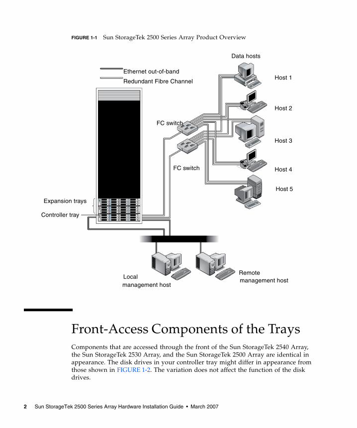
FIGURE 1-1 Sun StorageTek 2500 Series Array Product Overview
Front-Access Components of the TraysComponents that are accessed through the front of the Sun StorageTek 2540 Array,the Sun StorageTek 2530 Array, and the Sun StorageTek 2500 Array are identical inappearance. The disk drives in your controller tray might differ in appearance fromthose shown in FIGURE 1-2. The variation does not affect the function of the diskdrives.
Expansion trays
Controller tray
Localmanagement host
Remotemanagement host
Host 1
Host 2
Host 3
Host 4
Redundant Fibre Channel
FC switch
FC switch
Ethernet out-of-band
Data hosts
Host 5
2 Sun StorageTek 2500 Series Array Hardware Installation Guide • March 2007
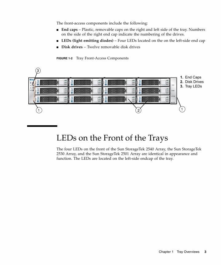
The front-access components include the following:
■ End caps – Plastic, removable caps on the right and left side of the tray. Numberson the side of the right end cap indicate the numbering of the drives.
■ LEDs (light emitting diodes) – Four LEDs located on the on the left-side end cap
■ Disk drives – Twelve removable disk drives
FIGURE 1-2 Tray Front-Access Components
LEDs on the Front of the TraysThe four LEDs on the front of the Sun StorageTek 2540 Array, the Sun StorageTek2530 Array, and the Sun StorageTek 2501 Array are identical in appearance andfunction. The LEDs are located on the left-side endcap of the tray.
1. End Caps2. Disk Drives3. Tray LEDs
11 2
3
Chapter 1 Tray Overviews 3
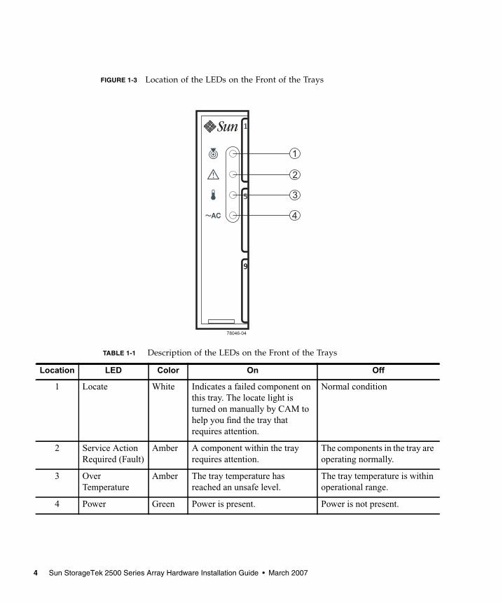
FIGURE 1-3 Location of the LEDs on the Front of the Trays
TABLE 1-1 Description of the LEDs on the Front of the Trays
Location LED Color On Off
1 Locate White Indicates a failed component onthis tray. The locate light isturned on manually by CAM tohelp you find the tray thatrequires attention.
Normal condition
2 Service ActionRequired (Fault)
Amber A component within the trayrequires attention.
The components in the tray areoperating normally.
3 OverTemperature
Amber The tray temperature hasreached an unsafe level.
The tray temperature is withinoperational range.
4 Power Green Power is present. Power is not present.
4 Sun StorageTek 2500 Series Array Hardware Installation Guide • March 2007
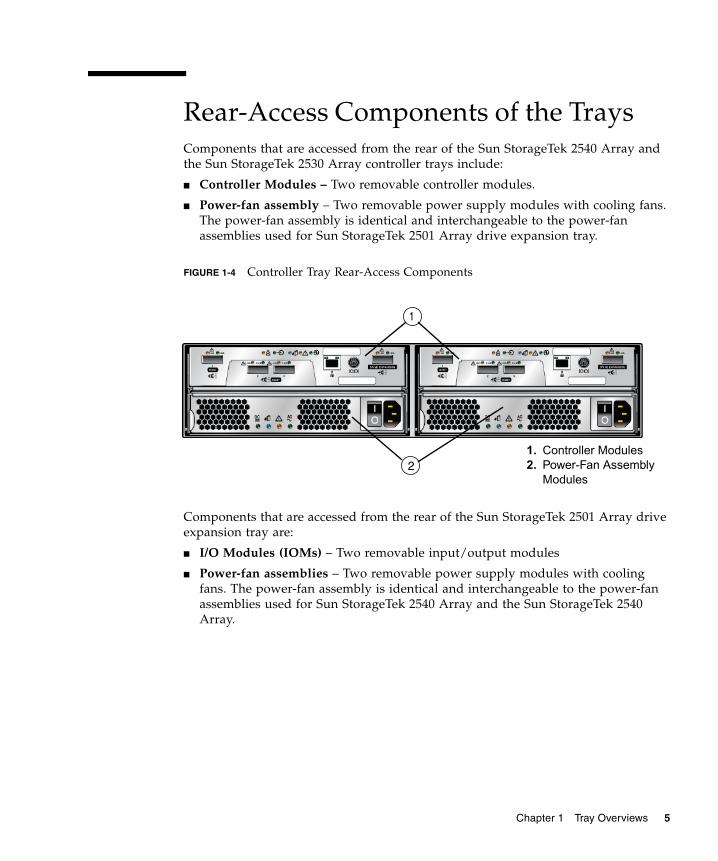
Rear-Access Components of the TraysComponents that are accessed from the rear of the Sun StorageTek 2540 Array andthe Sun StorageTek 2530 Array controller trays include:
■ Controller Modules – Two removable controller modules.
■ Power-fan assembly – Two removable power supply modules with cooling fans.The power-fan assembly is identical and interchangeable to the power-fanassemblies used for Sun StorageTek 2501 Array drive expansion tray.
FIGURE 1-4 Controller Tray Rear-Access Components
Components that are accessed from the rear of the Sun StorageTek 2501 Array driveexpansion tray are:
■ I/O Modules (IOMs) – Two removable input/output modules
■ Power-fan assemblies – Two removable power supply modules with coolingfans. The power-fan assembly is identical and interchangeable to the power-fanassemblies used for Sun StorageTek 2540 Array and the Sun StorageTek 2540Array.
1. Controller Modules2. Power-Fan Assembly
Modules
1
2
Chapter 1 Tray Overviews 5
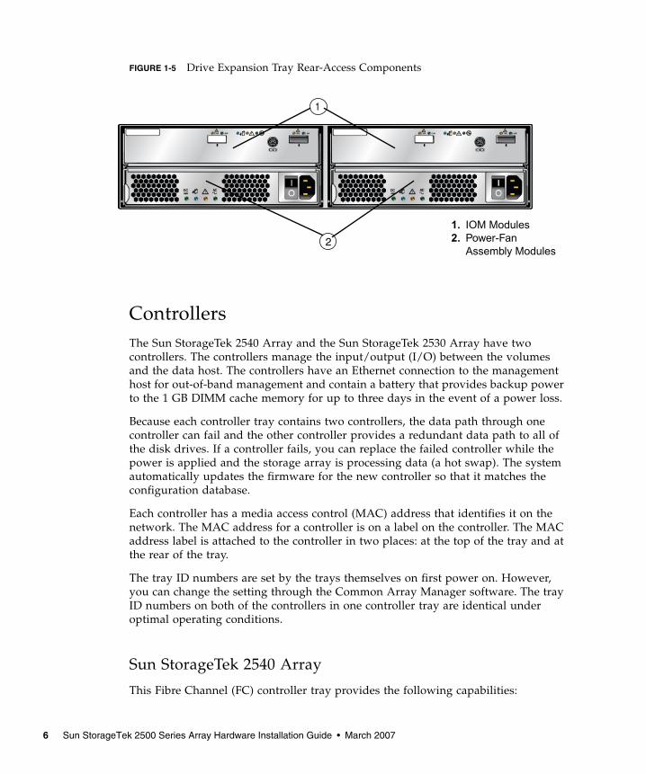
FIGURE 1-5 Drive Expansion Tray Rear-Access Components
ControllersThe Sun StorageTek 2540 Array and the Sun StorageTek 2530 Array have twocontrollers. The controllers manage the input/output (I/O) between the volumesand the data host. The controllers have an Ethernet connection to the managementhost for out-of-band management and contain a battery that provides backup powerto the 1 GB DIMM cache memory for up to three days in the event of a power loss.
Because each controller tray contains two controllers, the data path through onecontroller can fail and the other controller provides a redundant data path to all ofthe disk drives. If a controller fails, you can replace the failed controller while thepower is applied and the storage array is processing data (a hot swap). The systemautomatically updates the firmware for the new controller so that it matches theconfiguration database.
Each controller has a media access control (MAC) address that identifies it on thenetwork. The MAC address for a controller is on a label on the controller. The MACaddress label is attached to the controller in two places: at the top of the tray and atthe rear of the tray.
The tray ID numbers are set by the trays themselves on first power on. However,you can change the setting through the Common Array Manager software. The trayID numbers on both of the controllers in one controller tray are identical underoptimal operating conditions.
Sun StorageTek 2540 Array
This Fibre Channel (FC) controller tray provides the following capabilities:
1. IOM Modules2. Power-Fan
Assembly Modules
1
2
6 Sun StorageTek 2500 Series Array Hardware Installation Guide • March 2007
■ Two data host connectors per controller that can support either a fiber-opticinterface or a copper interface with 1, 2, or 4 Gb/s data host connection speed
■ One drive expansion tray Serial Attached SCSI (SAS) connector with 3 Gb/s driveexpansion tray connection speed
■ 512-MB or 1-GB mirrored cache
■ Maximum connection of 36 disk drives (one controller tray and two driveexpansion trays)
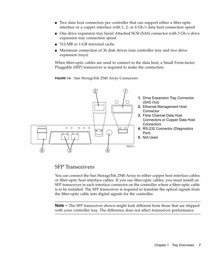
When fiber-optic cables are used to connect to the data host, a Small Form-factorPluggable (SFP) transceiver is required to make the connection.
FIGURE 1-6 Sun StorageTek 2540 Array Connectors
SFP Transceivers
You can connect the Sun StorageTek 2540 Array to either copper host interface cablesor fiber-optic host interface cables. If you use fiber-optic cables, you must install anSFP transceiver in each interface connector on the controller where a fiber-optic cableis to be installed. The SFP transceiver is required to translate the optical signals fromthe fiber-optic cable into digital signals for the controller.
Note – The SFP transceiver shown might look different from those that are shippedwith your controller tray. The difference does not affect transceiver performance.
1. Drive Expansion Tray Connector(SAS Out)
2. Ethernet Management HostConnector
3. Fibre Channel Data HostConnectors or Copper Data HostConnectors
4. RS-232 Connector (DiagnosticsPort)
5. Not Used
Chapter 1 Tray Overviews 7
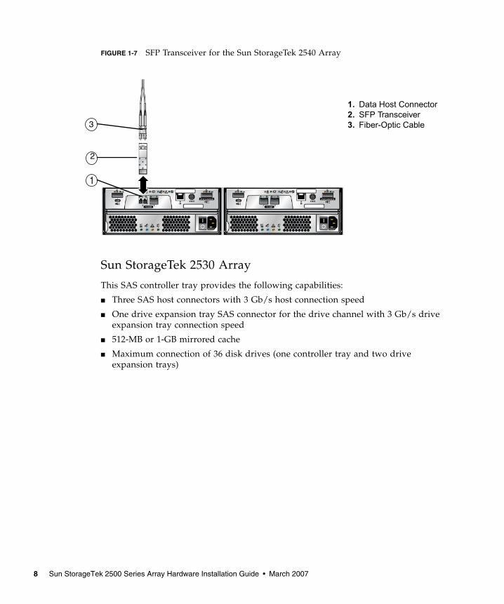
FIGURE 1-7 SFP Transceiver for the Sun StorageTek 2540 Array
Sun StorageTek 2530 Array
This SAS controller tray provides the following capabilities:
■ Three SAS host connectors with 3 Gb/s host connection speed
■ One drive expansion tray SAS connector for the drive channel with 3 Gb/s driveexpansion tray connection speed
■ 512-MB or 1-GB mirrored cache
■ Maximum connection of 36 disk drives (one controller tray and two driveexpansion trays)
1. Data Host Connector2. SFP Transceiver3. Fiber-Optic Cable3
2
1
8 Sun StorageTek 2500 Series Array Hardware Installation Guide • March 2007

FIGURE 1-8 Sun StorageTek 2530 Array Controller Connectors
Controller Tray and Drive Expansion Tray Power-Fan AssemblyThe power-fan assembly for the Sun StorageTek 2540 Array, the Sun StorageTek 2530Array, and the Sun StorageTek 2501 Array is identical and interchangeable.
Note – A minimum of two disk drives must be operating in a controller tray or adrive expansion tray to avoid generating a power-fan assembly error.
The power-fan assembly contains an integrated cooling fan. The power supplyprovides power to the internal components by converting incoming AC voltage toDC voltage. The fan circulates air inside of the tray by pulling air in through thevents on the front of the assembly and pushing the air out of the vents on the backof each fan.
Each tray contains two power-fan assemblies. If one power supply is turned off ormalfunctions, the other power supply maintains electrical power to the tray.Likewise, the fans provide redundant cooling. If one of the fans in either fan housingfails, the remaining fan continues to provide sufficient cooling to operate the tray.The remaining fan runs at a higher speed until the failed fan is replaced. Replace thefailed fan as soon as possible.
1. Drive Expansion TrayConnector (SAS Out)
2. Ethernet Management HostConnector
3. SAS Data Host Connectors4. RS-232 Connector
(Diagnostics Port)
Chapter 1 Tray Overviews 9
Sun StorageTek 2501 ArrayThe drive expansion tray expands the storage capacity of a storage array. Thecontrollers in the controller tray can connect to the drive expansion tray and accessthe disk drives in the drive expansion tray for additional storage. A drive expansiontray contains both physical components (disk drives, IOMs, and power-fanassemblies) and logical components (virtual disks and volumes).
Drive Expansion Tray IOM
The drive expansion tray contains two IOMs that provide the interface between thedisk drives in the drive expansion tray and the controllers in the controller tray. TheIOM also monitors sub-system parameters. Each controller in the controller trayconnects to an IOM.
If one IOM fails, the other IOM provides a redundant data path to the disk drives.You can replace a failed IOM while the power to the storage array is turned on andthe storage array is processing data (a hot swap).
Drive Expansion Tray IOM Connectors
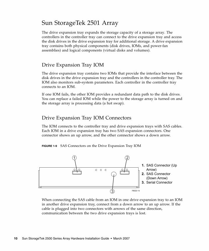
The IOM connects to the controller tray and drive expansion trays with SAS cables.Each IOM in a drive expansion tray has two SAS expansion connectors. Oneconnector shows an up arrow, and the other connector shows a down arrow.
FIGURE 1-9 SAS Connectors on the Drive Expansion Tray IOM
When connecting the SAS cable from an IOM in one drive expansion tray to an IOMin another drive expansion tray, connect from a down arrow to an up arrow. If thecable is plugged into two connectors with arrows of the same direction,communication between the two drive expansion trays is lost.
1. SAS Connector (UpArrow)
2. SAS Connector(Down Arrow)
3. Serial Connector
10 Sun StorageTek 2500 Series Array Hardware Installation Guide • March 2007
LEDs on the Rear of the Trays
Controller LEDs on the Sun StorageTek 2540Array
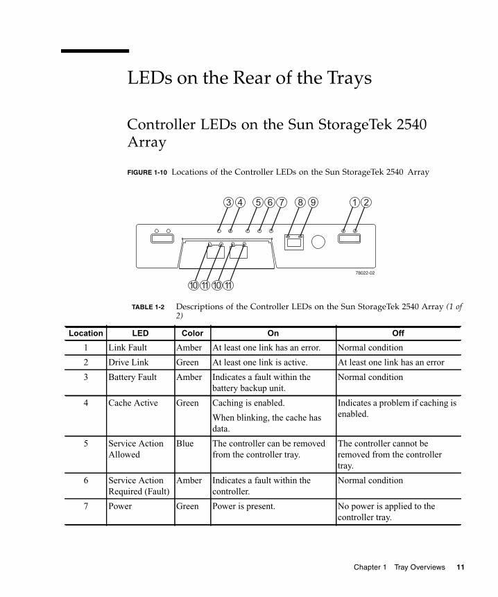
FIGURE 1-10 Locations of the Controller LEDs on the Sun StorageTek 2540 Array
TABLE 1-2 Descriptions of the Controller LEDs on the Sun StorageTek 2540 Array (1 of2)
Location LED Color On Off
1 Link Fault Amber At least one link has an error. Normal condition
2 Drive Link Green At least one link is active. At least one link has an error
3 Battery Fault Amber Indicates a fault within thebattery backup unit.
Normal condition
4 Cache Active Green Caching is enabled.
When blinking, the cache hasdata.
Indicates a problem if caching isenabled.
5 Service ActionAllowed
Blue The controller can be removedfrom the controller tray.
The controller cannot beremoved from the controllertray.
6 Service ActionRequired (Fault)
Amber Indicates a fault within thecontroller.
Normal condition
7 Power Green Power is present. No power is applied to thecontroller tray.
Chapter 1 Tray Overviews 11
Controller LEDs on the Sun StorageTek 2530Array
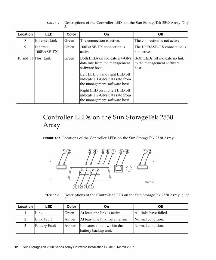
FIGURE 1-11 Locations of the Controller LEDs on the Sun StorageTek 2530 Array
8 Ethernet Link Green The connection is active. The connection is not active.
9 Ethernet100BASE-TX
Green 100BASE-TX connection isactive.
The 100BASE-TX connection isnot active.
10 and 11 Host Link Green Both LEDs on indicate a 4-Gb/sdata rate from the managementsoftware host.
Left LED on and right LED offindicate a 1-Gb/s data rate fromthe management software host.
Right LED on and left LED offindicate a 2-Gb/s data rate fromthe management software host.
Both LEDs off indicate no linkto the management softwarehost.
TABLE 1-3 Descriptions of the Controller LEDs on the Sun StorageTek 2530 Array (1 of2)
Location LED Color On Off
1 Link Green At least one link is active. All links have failed.
2 Link Fault Amber At least one link has an error. Normal condition.
3 Battery Fault Amber Indicates a fault within thebattery backup unit.
Normal condition.
TABLE 1-2 Descriptions of the Controller LEDs on the Sun StorageTek 2540 Array (2 of2)
Location LED Color On Off
12 Sun StorageTek 2500 Series Array Hardware Installation Guide • March 2007
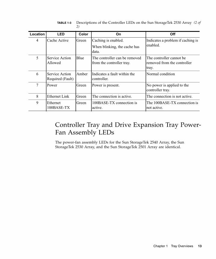
Controller Tray and Drive Expansion Tray Power-Fan Assembly LEDsThe power-fan assembly LEDs for the Sun StorageTek 2540 Array, the SunStorageTek 2530 Array, and the Sun StorageTek 2501 Array are identical.
4 Cache Active Green Caching is enabled.
When blinking, the cache hasdata.
Indicates a problem if caching isenabled.
5 Service ActionAllowed
Blue The controller can be removedfrom the controller tray.
The controller cannot beremoved from the controllertray.
6 Service ActionRequired (Fault)
Amber Indicates a fault within thecontroller.
Normal condition
7 Power Green Power is present. No power is applied to thecontroller tray.
8 Ethernet Link Green The connection is active. The connection is not active.
9 Ethernet100BASE-TX
Green 100BASE-TX connection isactive.
The 100BASE-TX connection isnot active.
TABLE 1-3 Descriptions of the Controller LEDs on the Sun StorageTek 2530 Array (2 of2)
Location LED Color On Off
Chapter 1 Tray Overviews 13
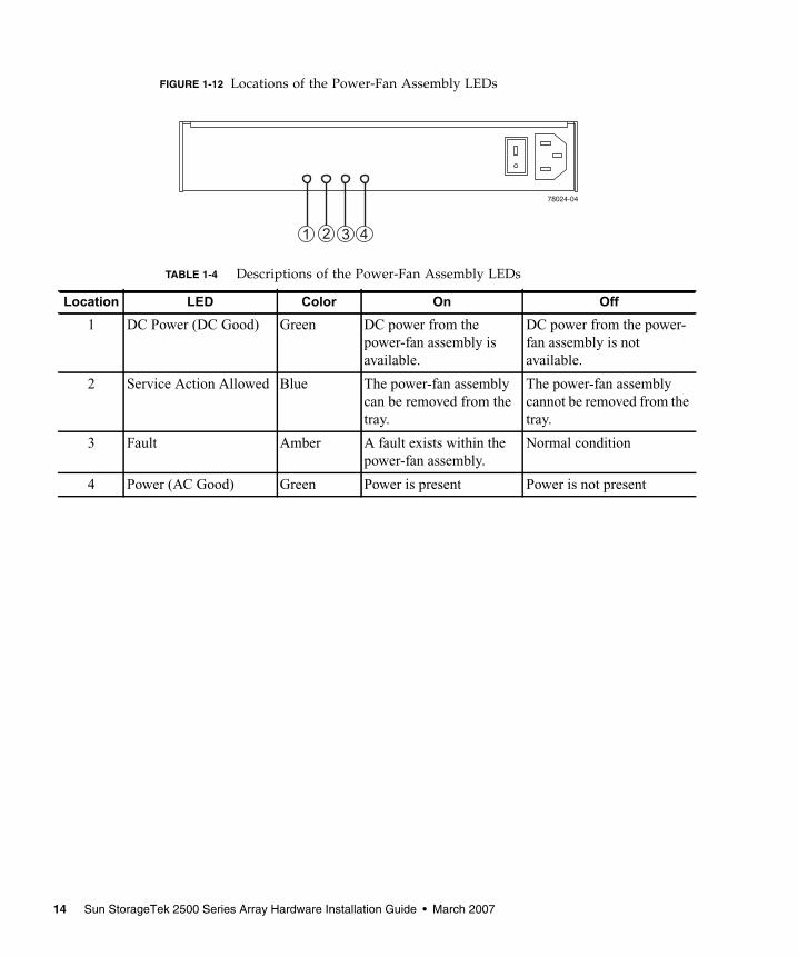
FIGURE 1-12 Locations of the Power-Fan Assembly LEDs
TABLE 1-4 Descriptions of the Power-Fan Assembly LEDs
Location LED Color On Off
1 DC Power (DC Good) Green DC power from thepower-fan assembly isavailable.
DC power from the power-fan assembly is notavailable.
2 Service Action Allowed Blue The power-fan assemblycan be removed from thetray.
The power-fan assemblycannot be removed from thetray.
3 Fault Amber A fault exists within thepower-fan assembly.
Normal condition
4 Power (AC Good) Green Power is present Power is not present
14 Sun StorageTek 2500 Series Array Hardware Installation Guide • March 2007
IOM LEDs on the Sun StorageTek 2501 Array
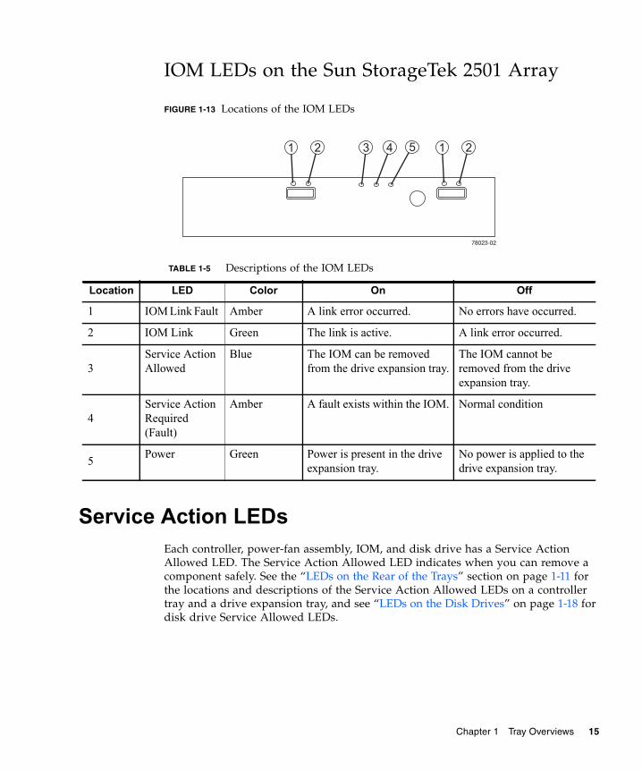
FIGURE 1-13 Locations of the IOM LEDs
Service Action LEDsEach controller, power-fan assembly, IOM, and disk drive has a Service ActionAllowed LED. The Service Action Allowed LED indicates when you can remove acomponent safely. See the “LEDs on the Rear of the Trays” section on page 1-11 forthe locations and descriptions of the Service Action Allowed LEDs on a controllertray and a drive expansion tray, and see “LEDs on the Disk Drives” on page 1-18 fordisk drive Service Allowed LEDs.
TABLE 1-5 Descriptions of the IOM LEDs
Location LED Color On Off
1 IOM Link Fault Amber A link error occurred. No errors have occurred.
2 IOM Link Green The link is active. A link error occurred.
3Service ActionAllowed
Blue The IOM can be removedfrom the drive expansion tray.
The IOM cannot beremoved from the driveexpansion tray.
4Service ActionRequired(Fault)
Amber A fault exists within the IOM. Normal condition
5Power Green Power is present in the drive
expansion tray.No power is applied to thedrive expansion tray.
Chapter 1 Tray Overviews 15
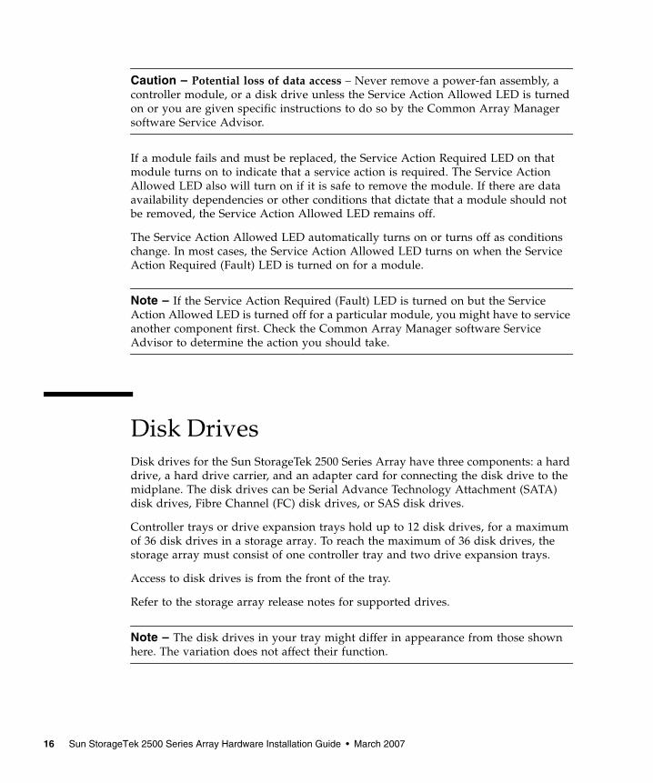
Caution – Potential loss of data access – Never remove a power-fan assembly, acontroller module, or a disk drive unless the Service Action Allowed LED is turnedon or you are given specific instructions to do so by the Common Array Managersoftware Service Advisor.
If a module fails and must be replaced, the Service Action Required LED on thatmodule turns on to indicate that a service action is required. The Service ActionAllowed LED also will turn on if it is safe to remove the module. If there are dataavailability dependencies or other conditions that dictate that a module should notbe removed, the Service Action Allowed LED remains off.
The Service Action Allowed LED automatically turns on or turns off as conditionschange. In most cases, the Service Action Allowed LED turns on when the ServiceAction Required (Fault) LED is turned on for a module.
Note – If the Service Action Required (Fault) LED is turned on but the ServiceAction Allowed LED is turned off for a particular module, you might have to serviceanother component first. Check the Common Array Manager software ServiceAdvisor to determine the action you should take.
Disk DrivesDisk drives for the Sun StorageTek 2500 Series Array have three components: a harddrive, a hard drive carrier, and an adapter card for connecting the disk drive to themidplane. The disk drives can be Serial Advance Technology Attachment (SATA)disk drives, Fibre Channel (FC) disk drives, or SAS disk drives.
Controller trays or drive expansion trays hold up to 12 disk drives, for a maximumof 36 disk drives in a storage array. To reach the maximum of 36 disk drives, thestorage array must consist of one controller tray and two drive expansion trays.
Access to disk drives is from the front of the tray.
Refer to the storage array release notes for supported drives.
Note – The disk drives in your tray might differ in appearance from those shownhere. The variation does not affect their function.
16 Sun StorageTek 2500 Series Array Hardware Installation Guide • March 2007
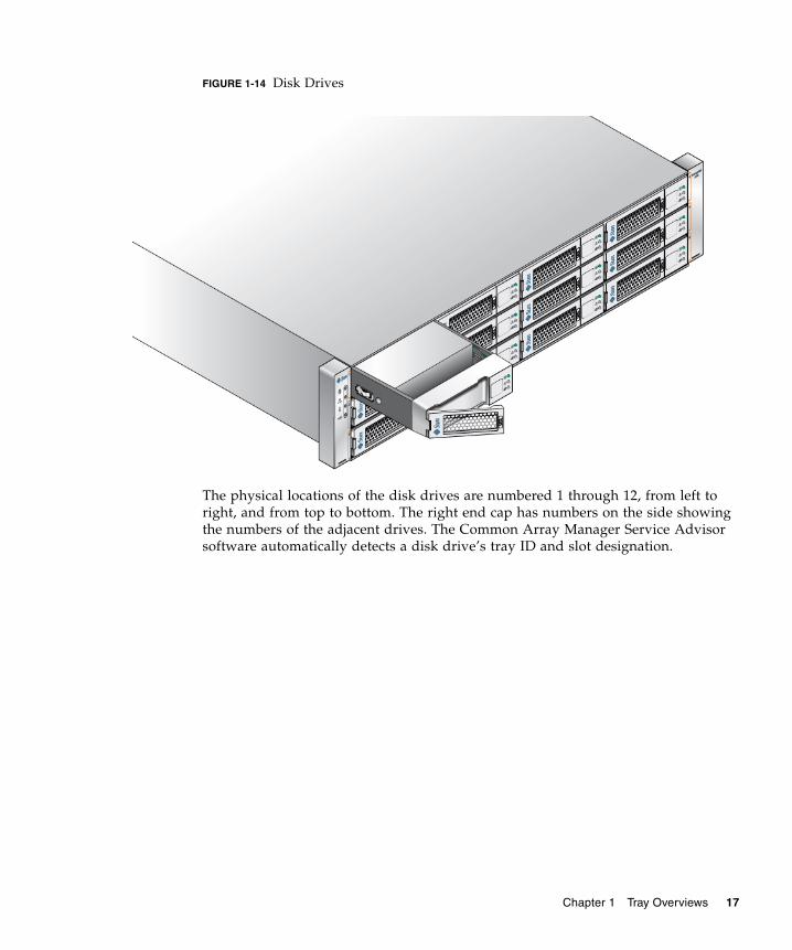
FIGURE 1-14 Disk Drives
The physical locations of the disk drives are numbered 1 through 12, from left toright, and from top to bottom. The right end cap has numbers on the side showingthe numbers of the adjacent drives. The Common Array Manager Service Advisorsoftware automatically detects a disk drive’s tray ID and slot designation.
Chapter 1 Tray Overviews 17
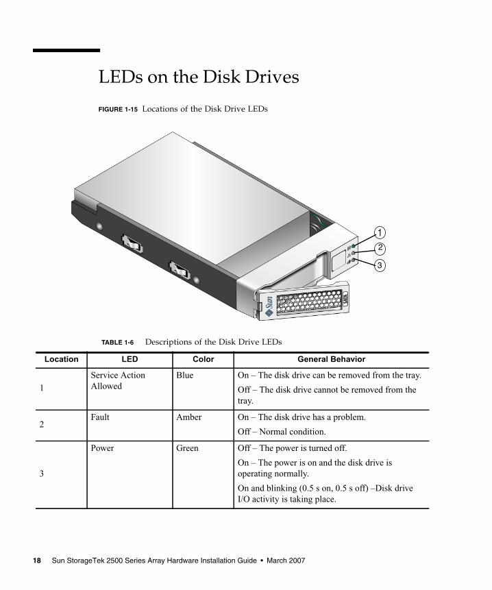
LEDs on the Disk Drives
FIGURE 1-15 Locations of the Disk Drive LEDs
TABLE 1-6 Descriptions of the Disk Drive LEDs
Location LED Color General Behavior
1Service ActionAllowed
Blue On – The disk drive can be removed from the tray.
Off – The disk drive cannot be removed from thetray.
2Fault Amber On – The disk drive has a problem.
Off – Normal condition.
3
Power Green Off – The power is turned off.
On – The power is on and the disk drive isoperating normally.
On and blinking (0.5 s on, 0.5 s off) –Disk driveI/O activity is taking place.
12
3
18 Sun StorageTek 2500 Series Array Hardware Installation Guide • March 2007
Common Array Manager SoftwareThe Sun StorageTek 2500 Series Array is managed by the Sun StorageTek CommonArray Manager software. The Common Array Manager provides web browser–based management and configuration from an external management host, data hostsoftware that controls the data path between the data host and the array, and aremote command-line interface (CLI) client that provides the same control andmonitoring capability as the web browser, and is scriptable for running frequentlyperformed tasks.
The Common Array Manager software includes Service Advisor, an online referencefull of hardware and software configuration and troubleshooting information andprocedures.
For information about installing the Common Array Manager software andconfiguring and managing the array, see the Sun StorageTek Common Array ManagerSoftware Installation Guide.
Service Advisor and Customer-Replaceable UnitsCustomer-replaceable units (CRUs) are designed to be replaceable by customers.
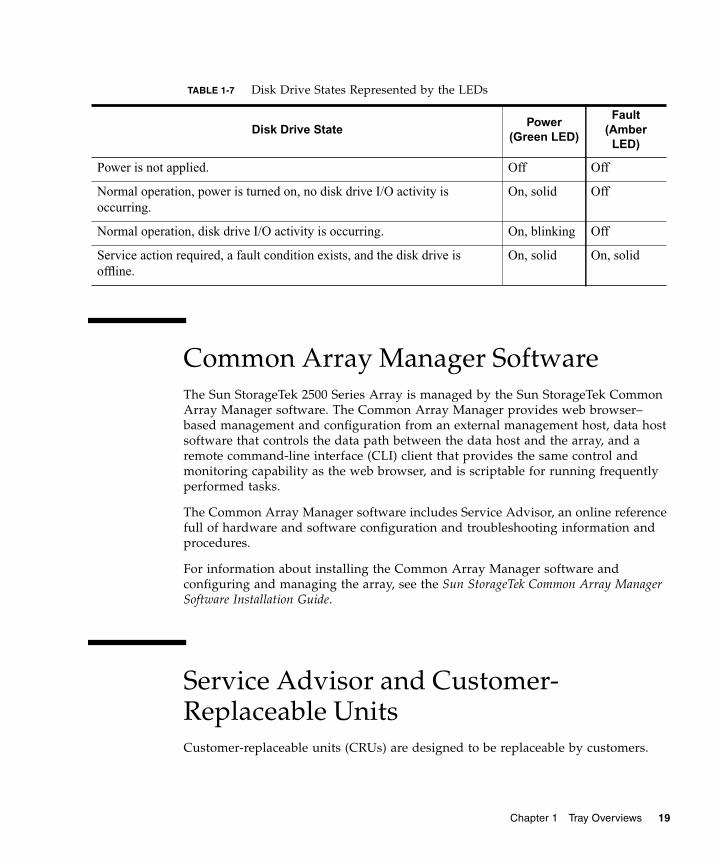
TABLE 1-7 Disk Drive States Represented by the LEDs
Disk Drive StatePower
(Green LED)
Fault(Amber
LED)
Power is not applied. Off Off
Normal operation, power is turned on, no disk drive I/O activity isoccurring.
On, solid Off
Normal operation, disk drive I/O activity is occurring. On, blinking Off
Service action required, a fault condition exists, and the disk drive isoffline.
On, solid On, solid
Chapter 1 Tray Overviews 19
To see a list of the hardware components that can be replaced at the customer siterefer to Service Advisor in the Sun StorageTek Common Array Manager software.
The Service Advisor also provides information and procedures for replacing arraycomponents.
Overview of the Installation ProcessBefore you begin to install the array, you must do the following:
■ Read the Sun StorageTek 2500 Series Array Release Notes for any late-breakinginformation related to the installation of the array.
■ Prepare the site as described in these books:
■ Sun StorageTek 2500 Series Array Regulatory and Safety Compliance Manual
■ Sun StorageTek 2500 Series Array Site Preparation Guide
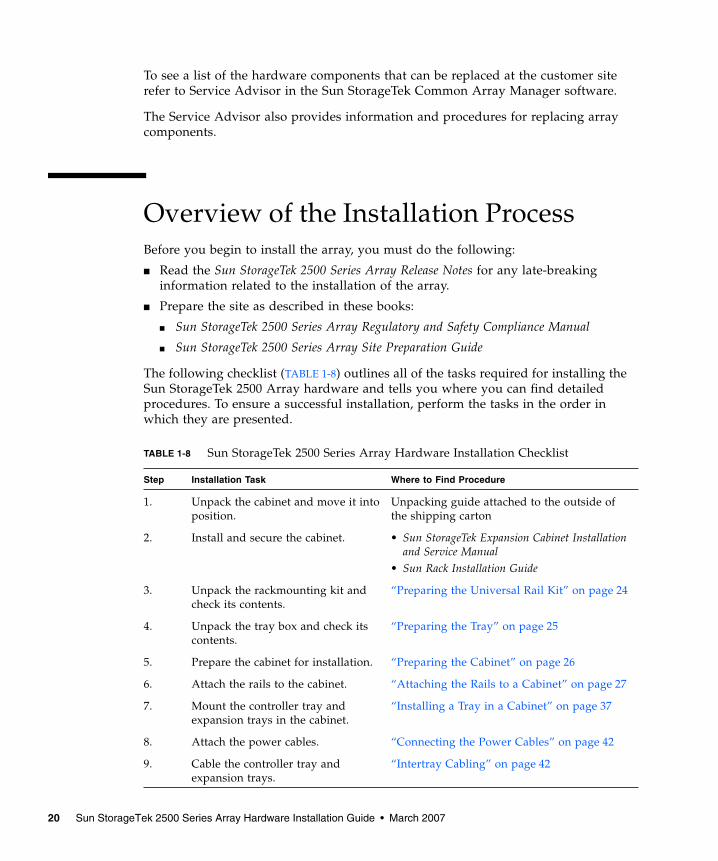
The following checklist (TABLE 1-8) outlines all of the tasks required for installing theSun StorageTek 2500 Array hardware and tells you where you can find detailedprocedures. To ensure a successful installation, perform the tasks in the order inwhich they are presented.
TABLE 1-8 Sun StorageTek 2500 Series Array Hardware Installation Checklist
Step Installation Task Where to Find Procedure
1. Unpack the cabinet and move it intoposition.
Unpacking guide attached to the outside ofthe shipping carton
2. Install and secure the cabinet. • Sun StorageTek Expansion Cabinet Installationand Service Manual
• Sun Rack Installation Guide
3. Unpack the rackmounting kit andcheck its contents.
“Preparing the Universal Rail Kit” on page 24
4. Unpack the tray box and check itscontents.
“Preparing the Tray” on page 25
5. Prepare the cabinet for installation. “Preparing the Cabinet” on page 26
6. Attach the rails to the cabinet. “Attaching the Rails to a Cabinet” on page 27
7. Mount the controller tray andexpansion trays in the cabinet.
“Installing a Tray in a Cabinet” on page 37
8. Attach the power cables. “Connecting the Power Cables” on page 42
9. Cable the controller tray andexpansion trays.
“Intertray Cabling” on page 42
20 Sun StorageTek 2500 Series Array Hardware Installation Guide • March 2007
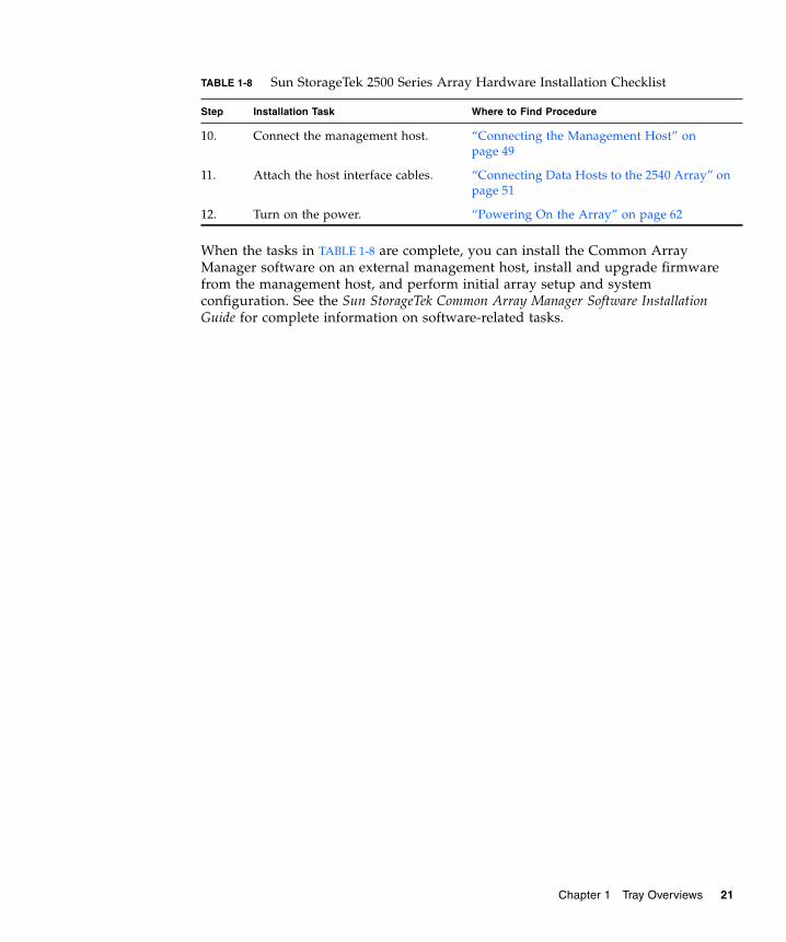
When the tasks in TABLE 1-8 are complete, you can install the Common ArrayManager software on an external management host, install and upgrade firmwarefrom the management host, and perform initial array setup and systemconfiguration. See the Sun StorageTek Common Array Manager Software InstallationGuide for complete information on software-related tasks.
10. Connect the management host. “Connecting the Management Host” onpage 49
11. Attach the host interface cables. “Connecting Data Hosts to the 2540 Array” onpage 51
12. Turn on the power. “Powering On the Array” on page 62
TABLE 1-8 Sun StorageTek 2500 Series Array Hardware Installation Checklist
Step Installation Task Where to Find Procedure
Chapter 1 Tray Overviews 21

22 Sun StorageTek 2500 Series Array Hardware Installation Guide • March 2007
CHAPTER 2
Installing Trays
Use the procedures in this chapter to install trays in a cabinet. The number of traysyou need to install depends on your overall storage requirements. You can install amaximum of three trays, one controller tray and up to two expansion trays for eacharray.
This chapter describes the process of installing the Sun StorageTek 2500 Series Array.It contains the following sections:
■ “Preparing for the Installation” on page 24
■ “Attaching the Rails to a Cabinet” on page 27
■ “Installing a Tray in a Cabinet” on page 37
■ “Connecting the Power Cables” on page 42
■ “Intertray Cabling” on page 42
■ “Drive Module Cable Labeling” on page 47
■ “Next Steps” on page 48
The installation procedures in this chapter require the following items:
■ #2 Phillips screwdriver (minimum 4-inch length recommended)
■ #3 Phillips screwdriver (minimum 4-inch length recommended)
■ Antistatic protection
Caution – Electrostatic discharge can damage sensitive components. Touching thearray or its components without using a proper ground might damage theequipment. To avoid damage, use proper antistatic protection before handling anycomponents.
23
Preparing for the InstallationUse the following procedures to prepare for installation:
■ “Preparing the Universal Rail Kit” on page 24
■ “Preparing the Tray” on page 25
■ “Preparing the Cabinet” on page 26
Preparing the Universal Rail KitUse the universal rail kit to mount the Sun StorageTek 2500 Series Array trays in anyof the following cabinets:
■ Any standard Sun cabinet, such as the Sun Rack 900/1000 cabinet
■ Any 19-inch wide, 4-post, EIA-compatible rack or cabinet with a front-to-backdepth between vertical cabinet rails of 24-36 inches (with threaded or unthreadedcabinet rails).
■ The Sun StorageTek Expansion cabinet
Unpacking the Universal Rail Kit
Unpack the universal rail kit and check the contents.
The universal rail kit (part number 594-2489-02) comes with pre-assembled rails andcontains the following items:
■ Left rail assembly
■ Right rail assembly
■ 10 8-32x3/8” panhead screws with lockwashers
■ 4 M4 flathead screws
■ 4 cabinet rail adapter plates (used for unthreaded cabinet rails only)
Loosening the Rail Adjustment Screws
To loosen the adjustment screws on the left and right rails:
Use a flathead screwdriver to loosen the two rail adjustment screws on each rail toallow adjustment of each rail length (FIGURE 2-1).
24 Sun StorageTek 2500 Series Array Hardware Installation Guide • March 2007
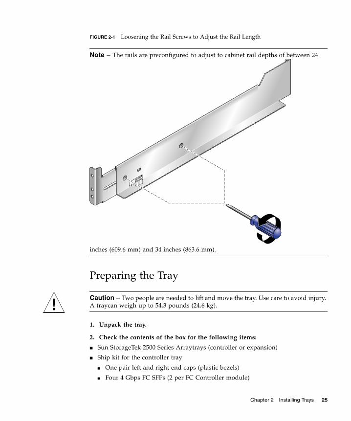
FIGURE 2-1 Loosening the Rail Screws to Adjust the Rail Length
Note – The rails are preconfigured to adjust to cabinet rail depths of between 24
inches (609.6 mm) and 34 inches (863.6 mm).
Preparing the Tray
Caution – Two people are needed to lift and move the tray. Use care to avoid injury.A traycan weigh up to 54.3 pounds (24.6 kg).
1. Unpack the tray.
2. Check the contents of the box for the following items:
■ Sun StorageTek 2500 Series Arraytrays (controller or expansion)
■ Ship kit for the controller tray
■ One pair left and right end caps (plastic bezels)
■ Four 4 Gbps FC SFPs (2 per FC Controller module)
Chapter 2 Installing Trays 25
■ Two 6-meter RJ45 -RJ45 Ethernet cables (one per controller module)
■ One RJ45-DIN9 cable
■ One RJ45-DB9 adapter
■ Sun StorageTek Common Array Manager Software CD
■ Sun StorageTek Common Array Manager Software Installation Guide (on thesoftware CD)
■ Common Array Manager sscs CLI Quick Reference Card
■ Sun StorageTek 2500 Series Array Hardware Installation Guide (Hardcopy)
■ Accessing Documentation guide
■ Premium feature license cards (ordered optionally)
■ Ship kit for each expansion tray
■ Two 1-meter copper SAS cables (one per I/O module)
■ Accessing Documentation guide
AC power cords are shipped separately with each tray.
Preparing the CabinetSelect the cabinet in which you will be installing the array. Be sure the cabinet isinstalled as described in the installation instructions provided with it.
1. Stabilize the cabinet as described in the cabinet documentation.
2. If the cabinet has casters, make sure the casters are locked to prevent thecabinet from rolling.
3. Remove or open the front panel.
4. Remove or open the vented back panel.
Planning the Order of the Tray InstallationInstall the trays starting with the controller tray at the lowest available 2RU tray slotin the cabinet. Next, install the expansion trays for the first controller tray. If roomremains in the cabinet, repeat for the next controller and expansion trays.
Starting at the bottom distributes the weight correctly in the cabinet.
26 Sun StorageTek 2500 Series Array Hardware Installation Guide • March 2007
Attaching the Rails to a CabinetDepending on the type of cabinetin which you will install the tray, use one of thefollowing procedures to attach the rails:
■ “Attaching the Universal Rail Kit to a Standard Sun or 19-Inch Cabinet WithThreaded Cabinet Rails” on page 27
■ “Attaching the Universal Rail Kit to a Standard 19-Inch Cabinet With UnthreadedCabinet Rails” on page 31
Each tray requires two standard mounting rack units (2RU) of vertical space in thecabinet. Each standard mounting rack unit (RU) has three mounting holes in the leftand right cabinet rails. The top mounting hole of the lower RU is always closest tothe bottom mounting hole of the upper RU, hence the divsion between RUs on acabinet rail is between the two closeest mounting holes in a grouping.
The universal rails have an adjustable depth of 24” to 34”.
Attaching the Universal Rail Kit to a StandardSun or 19-Inch Cabinet With Threaded CabinetRailsThis procedure describes the steps to attach the universal rail kit to:
■ All standard Sun cabinets, including the Sun Rack 900/1000 cabinets
■ Sun StorageTek Expansion cabinets
■ All 19-inch wide, 4-post EIA-compatible racks and cabinets with the followingcabinet rail types:
■ M5 threaded
■ M6 threaded
■ 10-32 threaded
■ 12-24 threaded
■ circular unthreaded
1. To attach the universal rail kit to a cabinet withthese cabinet rail typesPositionthe front flange of the left universal rail behind the left front cabinet rail(FIGURE 2-2).
Chapter 2 Installing Trays 27
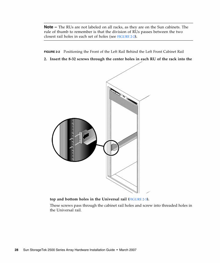
Note – The RUs are not labeled on all racks, as they are on the Sun cabinets. Therule of thumb to remember is that the division of RUs passes between the twoclosest rail holes in each set of holes (see FIGURE 2-2).
FIGURE 2-2 Positioning the Front of the Left Rail Behind the Left Front Cabinet Rail
2. Insert the 8-32 screws through the center holes in each RU of the rack into the
top and bottom holes in the Universal rail (FIGURE 2-3).
These screws pass through the cabinet rail holes and screw into threaded holes inthe Universal rail.
28 Sun StorageTek 2500 Series Array Hardware Installation Guide • March 2007
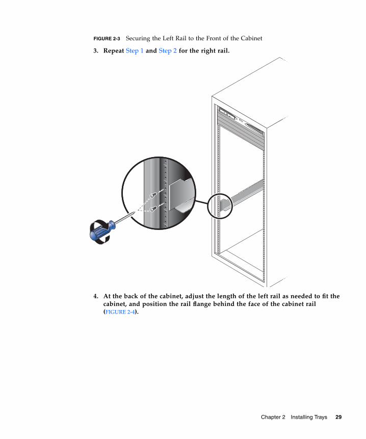
FIGURE 2-3 Securing the Left Rail to the Front of the Cabinet
3. Repeat Step 1 and Step 2 for the right rail.
4. At the back of the cabinet, adjust the length of the left rail as needed to fit thecabinet, and position the rail flange behind the face of the cabinet rail(FIGURE 2-4).
Chapter 2 Installing Trays 29
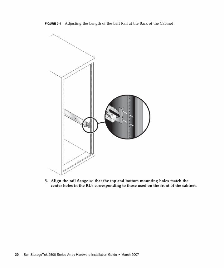
FIGURE 2-4 Adjusting the Length of the Left Rail at the Back of the Cabinet
5. Align the rail flange so that the top and bottom mounting holes match thecenter holes in the RUs corresponding to those used on the front of the cabinet.
30 Sun StorageTek 2500 Series Array Hardware Installation Guide • March 2007
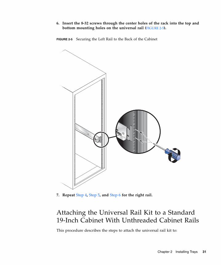
6. Insert the 8-32 screws through the center holes of the rack into the top andbottom mounting holes on the universal rail (FIGURE 2-5).
FIGURE 2-5 Securing the Left Rail to the Back of the Cabinet
7. Repeat Step 4, Step 5, and Step 6 for the right rail.
Attaching the Universal Rail Kit to a Standard19-Inch Cabinet With Unthreaded Cabinet RailsThis procedure describes the steps to attach the universal rail kit to:
Chapter 2 Installing Trays 31
■ All 19-inch wide, 4-post EIA-compatible racks and cabinets with unthreadedcabinet rails (square hole racks).
To attach the universal rail kit to a cabinet with unthreaded cabinet rails, followthese steps first for the left rail and then for the right rail:
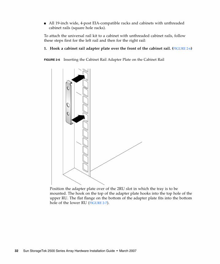
1. Hook a cabinet rail adapter plate over the front of the cabinet rail. (FIGURE 2-6)
FIGURE 2-6 Inserting the Cabinet Rail Adapter Plate on the Cabinet Rail
Position the adapter plate over of the 2RU slot in which the tray is to bemounted. The hook on the top of the adapter plate hooks into the top hole of theupper RU. The flat flange on the bottom of the adapter plate fits into the bottomhole of the lower RU (FIGURE 2-7).
32 Sun StorageTek 2500 Series Array Hardware Installation Guide • March 2007
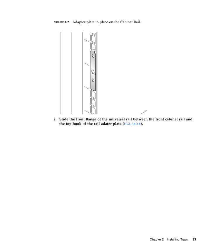
FIGURE 2-7 Adapter plate in place on the Cabinet Rail.
2. Slide the front flange of the universal rail between the front cabinet rail andthe top hook of the rail adater plate (FIGURE 2-8).
Chapter 2 Installing Trays 33
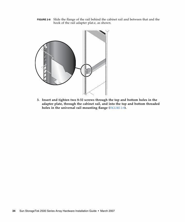
FIGURE 2-8 Slide the flange of the rail behind the cabinet rail and between that and thehook of the rail adapter plat.e, as shown.
3. Insert and tighten two 8-32 screws through the top and bottom holes in theadapter plate, through the cabinet rail, and into the top and bottom threadedholes in the universal rail mounting flange (FIGURE 2-9).
34 Sun StorageTek 2500 Series Array Hardware Installation Guide • March 2007
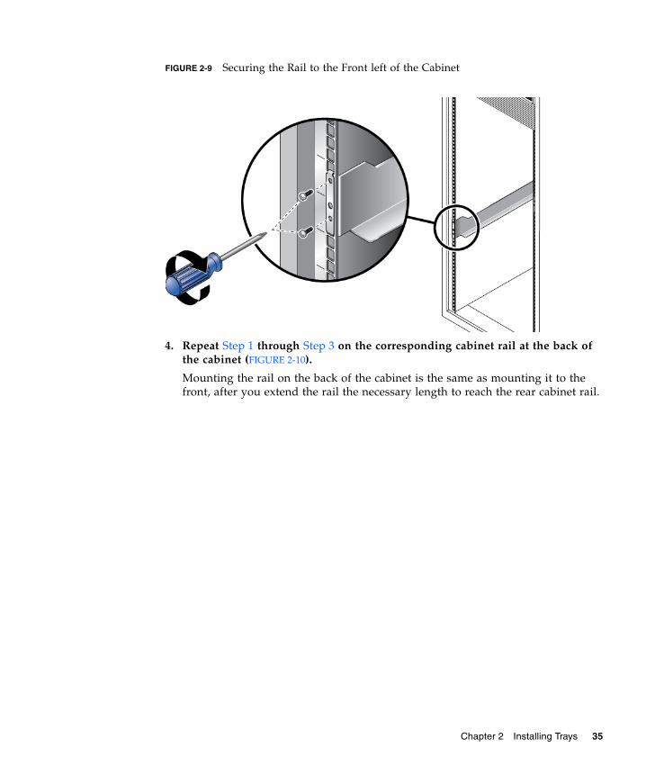
FIGURE 2-9 Securing the Rail to the Front left of the Cabinet
4. Repeat Step 1 through Step 3 on the corresponding cabinet rail at the back ofthe cabinet (FIGURE 2-10).
Mounting the rail on the back of the cabinet is the same as mounting it to thefront, after you extend the rail the necessary length to reach the rear cabinet rail.
Chapter 2 Installing Trays 35
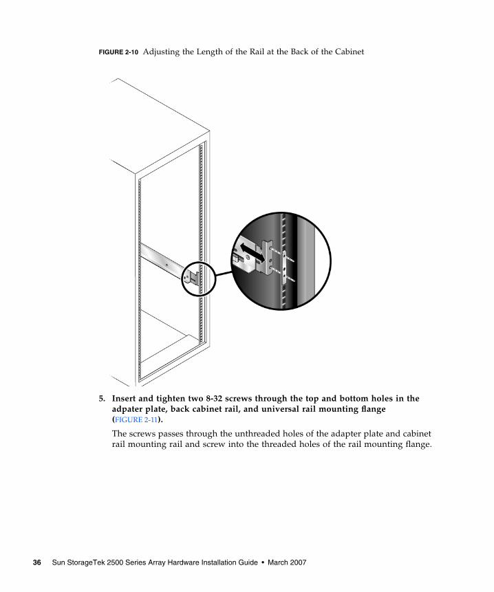
FIGURE 2-10 Adjusting the Length of the Rail at the Back of the Cabinet
5. Insert and tighten two 8-32 screws through the top and bottom holes in theadpater plate, back cabinet rail, and universal rail mounting flange(FIGURE 2-11).
The screws passes through the unthreaded holes of the adapter plate and cabinetrail mounting rail and screw into the threaded holes of the rail mounting flange.
36 Sun StorageTek 2500 Series Array Hardware Installation Guide • March 2007
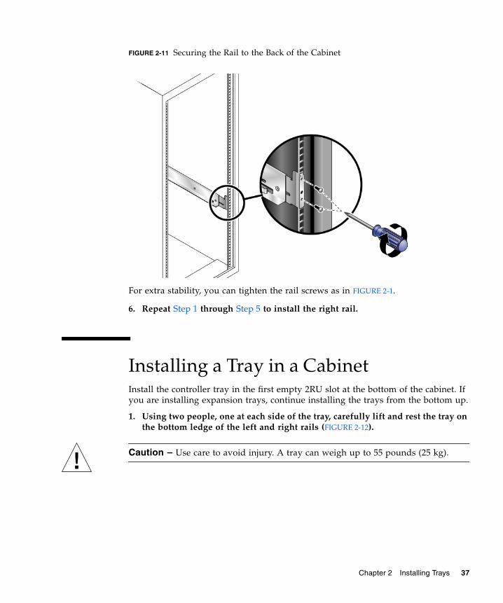
FIGURE 2-11 Securing the Rail to the Back of the Cabinet
For extra stability, you can tighten the rail screws as in FIGURE 2-1.
6. Repeat Step 1 through Step 5 to install the right rail.
Installing a Tray in a CabinetInstall the controller tray in the first empty 2RU slot at the bottom of the cabinet. Ifyou are installing expansion trays, continue installing the trays from the bottom up.
1. Using two people, one at each side of the tray, carefully lift and rest the tray onthe bottom ledge of the left and right rails (FIGURE 2-12).
Caution – Use care to avoid injury. A tray can weigh up to 55 pounds (25 kg).
Chapter 2 Installing Trays 37
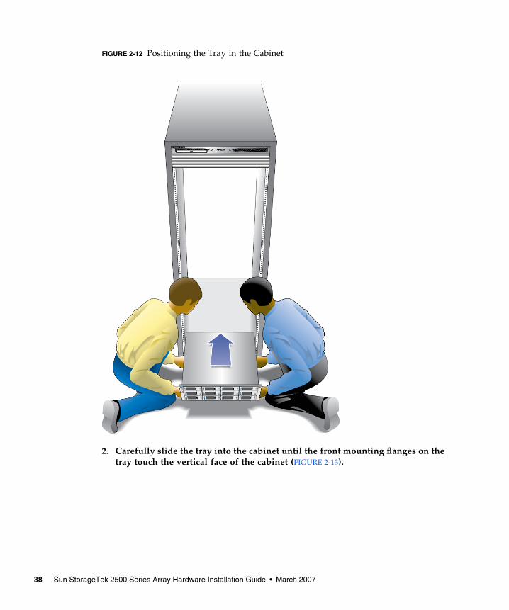
FIGURE 2-12 Positioning the Tray in the Cabinet
2. Carefully slide the tray into the cabinet until the front mounting flanges on thetray touch the vertical face of the cabinet (FIGURE 2-13).
38 Sun StorageTek 2500 Series Array Hardware Installation Guide • March 2007
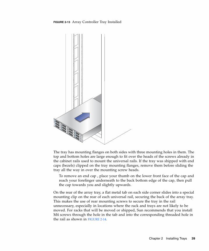
FIGURE 2-13 Array Controller Tray Installed
The tray has mounting flanges on both sides with three mounting holes in them. Thetop and bottom holes are large enough to fit over the heads of the screws already inthe cabinet rails used to mount the universal rails. If the tray was shipped with endcaps (bezels) clipped on the tray mounting flanges, remove them before sliding thetray all the way in over the mounting screw heads.
To remove an end cap , place your thumb on the lower front face of the cap andreach your forefinger underneath to the back bottom edge of the cap, then pullthe cap towards you and slightly upwards.
On the rear of the array tray, a flat metal tab on each side corner slides into a specialmounting clip on the rear of each universal rail, securing the back of the array tray.This makes the use of rear mounting screws to secure the tray in the railunnecessary, especially in locations where the rack and trays are not likely to bemoved. For racks that will be moved or shipped, Sun recommends that you installM4 screws through the hole in the tab and into the corresponding threaded hole inthe rail as shown in FIGURE 2-14.
Chapter 2 Installing Trays 39
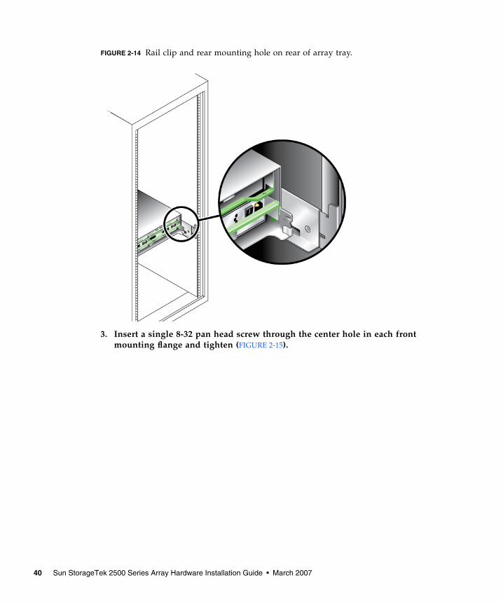
FIGURE 2-14 Rail clip and rear mounting hole on rear of array tray.
3. Insert a single 8-32 pan head screw through the center hole in each frontmounting flange and tighten (FIGURE 2-15).
40 Sun StorageTek 2500 Series Array Hardware Installation Guide • March 2007
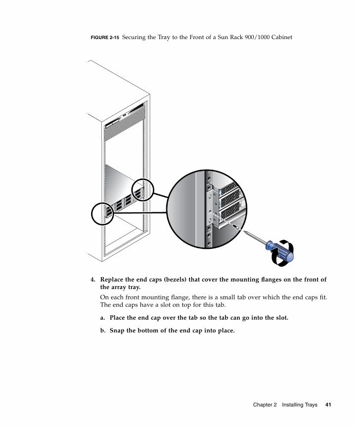
FIGURE 2-15 Securing the Tray to the Front of a Sun Rack 900/1000 Cabinet
4. Replace the end caps (bezels) that cover the mounting flanges on the front ofthe array tray.
On each front mounting flange, there is a small tab over which the end caps fit.The end caps have a slot on top for this tab.
a. Place the end cap over the tab so the tab can go into the slot.
b. Snap the bottom of the end cap into place.
Chapter 2 Installing Trays 41
Connecting the Power Cables1. Verify that both power switches are turned off.
2. Verify that the circuit breakers in the cabinet are turned off.
3. Connect each power supply in the tray to a separate power source in thecabinet.
4. Connect the primary power cables from the cabinet to the external powersource.
Note – Do not power on the array until you complete the procedures in this chapter.The power-on sequence is described in detail in Chapter 4.
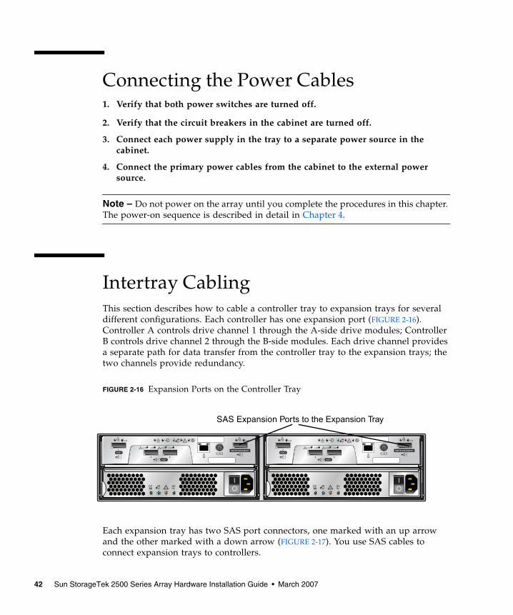
Intertray CablingThis section describes how to cable a controller tray to expansion trays for severaldifferent configurations. Each controller has one expansion port (FIGURE 2-16).Controller A controls drive channel 1 through the A-side drive modules; ControllerB controls drive channel 2 through the B-side modules. Each drive channel providesa separate path for data transfer from the controller tray to the expansion trays; thetwo channels provide redundancy.
FIGURE 2-16 Expansion Ports on the Controller Tray
Each expansion tray has two SAS port connectors, one marked with an up arrowand the other marked with a down arrow (FIGURE 2-17). You use SAS cables toconnect expansion trays to controllers.
Link Link
HOST1
SAS
LinkLink LinkLink
HOST2 3
SAS
Link Link
DRIVE EXPANSIONSAS
Link Link
HOST1
SAS
LinkLink LinkLink
HOST2 3
SAS
Link Link
DRIVE EXPANSIONSAS
SAS Expansion Ports to the Expansion Tray
42 Sun StorageTek 2500 Series Array Hardware Installation Guide • March 2007
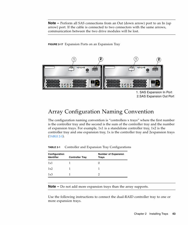
Note – Perform all SAS connections from an Out (down arrow) port to an In (uparrow) port. If the cable is connected to two connectors with the same arrows,communication between the two drive modules will be lost.
FIGURE 2-17 Expansion Ports on an Expansion Tray
Array Configuration Naming ConventionThe configuration naming convention is “controllers x trays” where the first numberis the controller tray and the second is the sum of the controller tray and the numberof expansion trays. For example, 1x1 is a standalone controller tray, 1x2 is thecontroller tray and one expansion tray, 1x is the controller tray and 2expansion trays(TABLE 2-1).
Note – Do not add more expansion trays than the array supports.
Use the following instructions to connect the dual-RAID controller tray to one ormore expansion trays.
TABLE 2-1 Controller and Expansion Tray Configurations
ConfigurationIdentifier Controller Tray
Number of ExpansionTrays
1x1 1 0
1x2 1 1
1x3 1 2
1. SAS Expansion In Port2.SAS Expansion Out Port
1 2222 22221
Chapter 2 Installing Trays 43
Connecting Expansion TraysKeep the following points in mind when adding expansion trays to your storagearray:
■ Expansion trays must be added with power to the array and I/O data transferturned off. If you need to add an expansion tray to an array that cannot be takenoff-line, contact your Sun Technical Support representative before attempting toconnect the new tray.
■ Controller and expansion trays are shipped with protective plastic plugs in theSAS expansion ports. You must remove these before connecting cables.
■ Expansion trays are added serially, in a chain (actually two chains: channel onethrough the A-side controller and modules, and channel two through the B-sidecontroller and modules). The SAS cable from the expansion port on a controllerconnects to the In port (Up arrow) on an expansion tray drive module. The SAScable from a drive module on expansion tray 1 to a corresponding drive moduleon expansion tray 2 connects from the Out port on expansion tray 1 to thecorresponding In port on expansion tray 2. This pattern repeats for eachadditional drive module on a channel. See FIGURE 2-19 for an illustration of thisreverse cabling pattern.
■ To connect cables for maximum redundancy, controller B must be cabled to theexpansion tray B-side modules in the opposite order as the expansion tray A-sidemodules. That means the last drive module in the A-side chain from controller Amust be the first drive module in the B-side chain from controller B. SeeFIGURE 2-19 for an illustration of cabling for maximum tray level redundancy.
■ On all SAS cables, affix a label to each end of the cable. See “Drive Module CableLabeling” on page 47 for labeling tips.
44 Sun StorageTek 2500 Series Array Hardware Installation Guide • March 2007
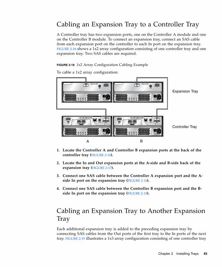
Cabling an Expansion Tray to a Controller TrayA Controller tray has two expansion ports, one on the Controller A module and oneon the Controller B module. To connect an expansion tray, connect an SAS cablefrom each expansion port on the controller to each In port on the expansion tray.FIGURE 2-18 shows a 1x2 array configuration consisting of one controller tray and oneexpansion tray. Two SAS cables are required.
FIGURE 2-18 1x2 Array Configuration Cabling Example
To cable a 1x2 array configuration:
1. Locate the Controller A and Controller B expansion ports at the back of thecontroller tray (FIGURE 2-16).
2. Locate the In and Out expansion ports at the A-side and B-side back of theexpansion tray (FIGURE 2-17).
3. Connect one SAS cable between the Controller A expansion port and the A-side In port on the expansion tray (FIGURE 2-18).
4. Connect one SAS cable between the Controller B expansion port and the B-side In port on the expansion tray (FIGURE 2-18).
Cabling an Expansion Tray to Another ExpansionTrayEach additional expansion tray is added to the preceding expansion tray byconnecting SAS cables from the Out ports of the first tray to the In ports of the nexttray. FIGURE 2-19 illustrates a 1x3 array configuration consisting of one controller tray
A B
Controller Tray
Expansion Tray
Chapter 2 Installing Trays 45
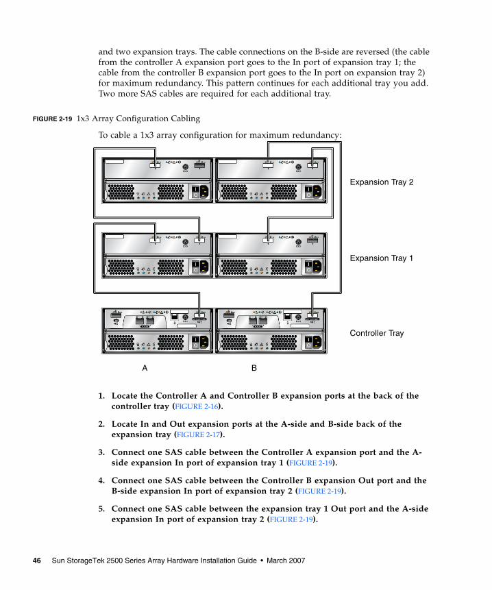
and two expansion trays. The cable connections on the B-side are reversed (the cablefrom the controller A expansion port goes to the In port of expansion tray 1; thecable from the controller B expansion port goes to the In port on expansion tray 2)for maximum redundancy. This pattern continues for each additional tray you add.Two more SAS cables are required for each additional tray.
FIGURE 2-19 1x3 Array Configuration Cabling
To cable a 1x3 array configuration for maximum redundancy:
1. Locate the Controller A and Controller B expansion ports at the back of thecontroller tray (FIGURE 2-16).
2. Locate In and Out expansion ports at the A-side and B-side back of theexpansion tray (FIGURE 2-17).
3. Connect one SAS cable between the Controller A expansion port and the A-side expansion In port of expansion tray 1 (FIGURE 2-19).
4. Connect one SAS cable between the Controller B expansion Out port and theB-side expansion In port of expansion tray 2 (FIGURE 2-19).
5. Connect one SAS cable between the expansion tray 1 Out port and the A-sideexpansion In port of expansion tray 2 (FIGURE 2-19).
A B
Controller Tray
Expansion Tray 1
Expansion Tray 2
46 Sun StorageTek 2500 Series Array Hardware Installation Guide • March 2007
6. Connect one SAS cable between the expansion tray 2 B-side Out port and theB-side In port of expansion tray 2 (FIGURE 2-19).
Drive Module Cable LabelingLabels for the drive cables identify which controller ports and which expansionconnections in an expansion tray you use when you attach cables between acontroller and the drive modules on an expansion tray. Cable labels are useful if youneed to disconnect cables to service a controller. Attach a label to each end of thecable. Use this design to create labels for drive cables:
■ Controller ID (for example, Controller A)
■ Expansion tray ID (for example, Tray A)
■ Expansion port ID (for example, In or Out)
■ Drive module ID
Example Label AbbreviationIn this example, the storage configuration has the following characteristics:
■ Drive channel 1
■ Controller A, drive channel 1
■ Drive module 1
■ Expansion Tray A (which is the left drive module), Out port
Using this design, the label includes the following information:
CtA-Dch1, Dm1-Tray_A (left), Out
Simplex ConfigurationsA simplex configuration is a 2530 Array with a single controller and a singlebackend channel. By definition, there is a single path SAS connection to the datahost, and no redundancy is available. There can be expansion modules on the singlebackend channel.
Chapter 2 Installing Trays 47
Simplex cabling is the same as the cabling on a single channel of an ordinary array,such as that shown on the A-side in FIGURE 2-18. CRU removal and replacementprocedures in a simplex configuration are the same as those for a duplexconfiguration with a failed controller (with the exception of the service procedurestargeted at the failed controller). These procedures are available in Service Advisor.Maintenance procedures such as firmware updates or servicing of the controller orexpansion modules will cause loss of access to the array during the performing ofthe procedure, since there is no backup channel.
Performance and default behavior are the same as a duplex configuration with afailed or missing controller. Write cache is by nature in write-through mode becausethere is no cache mirroring possible.
Next StepsNow you are ready to connect the management and data hosts, as described inChapter 3.
48 Sun StorageTek 2500 Series Array Hardware Installation Guide • March 2007
CHAPTER 3
Connecting the Management Hostand Data Hosts
This chapter describes Sun StorageTek 2500 Series Array cable connections for hosts.It contains the following sections:
■ “Connecting the Management Host” on page 49
■ “Connecting Data Hosts to the 2540 Array” on page 51
■ “Connecting Data Hosts to the 2530 Array” on page 56
■ “Host Cable Labeling” on page 59
■ “Next Steps” on page 59
Connecting the Management HostThe management host directly manages Sun StorageTek 2500 Series Arrays over anout-of-band network. This section describes how to setup a connection between theEthernet port of a controller (FIGURE 3-1) and the management host.
49
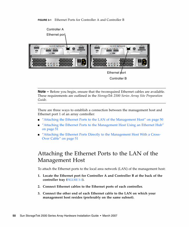
FIGURE 3-1 Ethernet Ports for Controller A and Controller B
Note – Before you begin, ensure that the tworequired Ethernet cables are available.These requirements are outlined in the StorageTek 2500 Series Array Site PreparationGuide.
There are three ways to establish a connection between the management host andEthernet port 1 of an array controller:
■ “Attaching the Ethernet Ports to the LAN of the Management Host” on page 50
■ “Attaching the Ethernet Ports to the Management Host Using an Ethernet Hub”on page 51
■ “Attaching the Ethernet Ports Directly to the Management Host With a Cross-Over Cable” on page 51
Attaching the Ethernet Ports to the LAN of theManagement HostTo attach the Ethernet ports to the local area network (LAN) of the management host:
1. Locate the Ethernet port for Controller A and Controller B at the back of thecontroller tray (FIGURE 3-1).
2. Connect Ethernet cables to the Ethernet ports of each controller.
3. Connect the other end of each Ethernet cable to the LAN on which yourmanagement host resides (preferably on the same subnet).
Link Link
HOST1
SAS
LinkLink LinkLink
HOST2 3
SAS
Link Link
DRIVE EXPANSIONSAS
Link Link
HOST1
SAS
LinkLink LinkLink
HOST2 3
SAS
Link Link
DRIVE EXPANSIONSAS
Controller B
Controller A
Ethernet port
Ethernet port
50 Sun StorageTek 2500 Series Array Hardware Installation Guide • March 2007
Attaching the Ethernet Ports to the ManagementHost Using an Ethernet HubTo attach the Ethernet ports and the management port Ethernet interface to anEthernet hub on a private subnet:
1. Locate Ethernet ports on Controller A and Controller B at the back of thecontroller tray (FIGURE 3-1).
2. Connect Ethernet cables to the Ethernet ports of each controller module.
3. Connect the other end of each Ethernet cable to an Ethernet hub.
4. Connect an Ethernet port on the management host to the Ethernet hub.
Attaching the Ethernet Ports Directly to theManagement Host With a Cross-Over Cable
Note – This method would typically be used only to establish temporary IPconnectivity between the management host and the controller’s Ethernet ports.
To attach the Ethernet ports directly to the management host using cross-over cables:
1. Locate the Ethernet ports for Controller A and Controller B at the back of thecontroller tray (FIGURE 3-1).
2. Obtain and connect Ethernet cross-over cables to the Ethernet port of eachcontroller module.
3. Connect the other end of each Ethernet cable directly to your management hostEthernet ports.
Connecting Data Hosts to the 2540 ArrayThe Sun StorageTek 2540 Array connects to data hosts through Fibre Channel (FC)cables.
Chapter 3 Connecting the Management Host and Data Hosts 51
Note – For maximum hardware redundancy, you must install a minimum of twoHBAs in each host. Dual-port HBAs give you two paths into the storage array but donot ensure redundancy if the HBA fails.
2540 Array Data Host Connection TopologiesYou can connect data hosts to access the Sun StorageTek 2540 Array directly to thearray, or through Fibre Channel (FC) switches to the array. The following figuresillustrate four possible host connection topologies for the 2540 Array:
■ Direct connection from a single data host server (FIGURE 3-2)
■ Direct connection from two data host servers (FIGURE 3-3)
■ Data host connection through Fiber Channel switch fabric (FIGURE 3-4)
■ Mixed connection, direct and through switch (FIGURE 3-5)
52 Sun StorageTek 2500 Series Array Hardware Installation Guide • March 2007
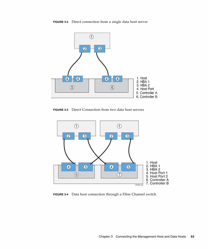
FIGURE 3-2 Direct connection from a single data host server
FIGURE 3-3 Direct Connection from two data host servers
FIGURE 3-4 Data host connection through a Fibre Channel switch
1. Host2. HBA 13. HBA 24. Host Port 15. Host Port 26. Controller A7. Controller B
Chapter 3 Connecting the Management Host and Data Hosts 53
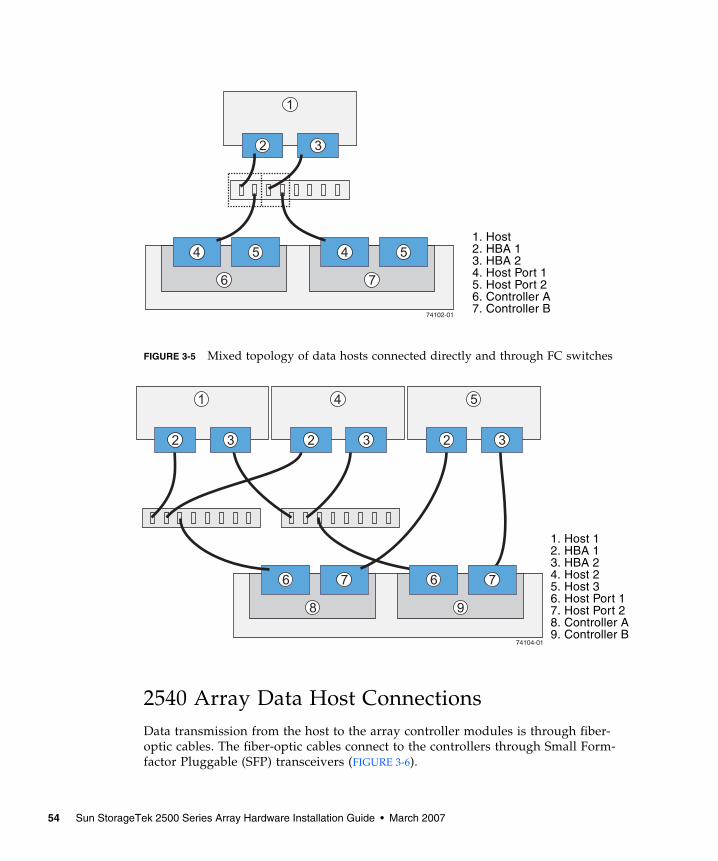
FIGURE 3-5 Mixed topology of data hosts connected directly and through FC switches
2540 Array Data Host ConnectionsData transmission from the host to the array controller modules is through fiber-optic cables. The fiber-optic cables connect to the controllers through Small Form-factor Pluggable (SFP) transceivers (FIGURE 3-6).
1. Host2. HBA 13. HBA 24. Host Port 15. Host Port 26. Controller A7. Controller B
1. Host 12. HBA 13. HBA 24. Host 25. Host 36. Host Port 17. Host Port 28. Controller A9. Controller B
54 Sun StorageTek 2500 Series Array Hardware Installation Guide • March 2007
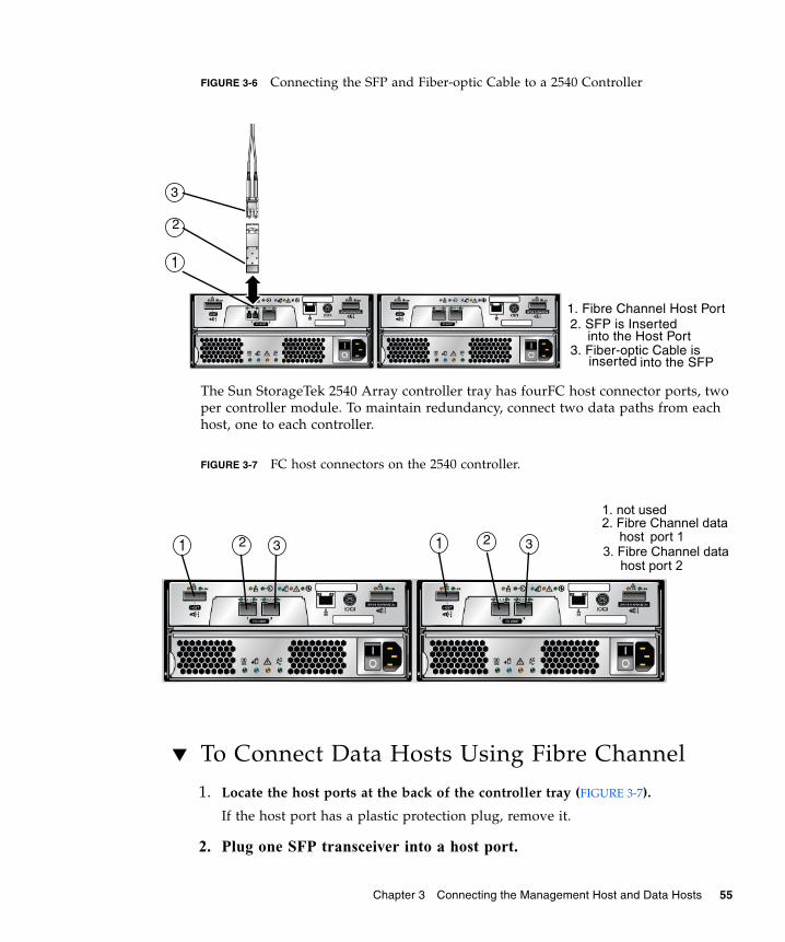
FIGURE 3-6 Connecting the SFP and Fiber-optic Cable to a 2540 Controller
The Sun StorageTek 2540 Array controller tray has fourFC host connector ports, twoper controller module. To maintain redundancy, connect two data paths from eachhost, one to each controller.
FIGURE 3-7 FC host connectors on the 2540 controller.
▼ To Connect Data Hosts Using Fibre Channel
1. Locate the host ports at the back of the controller tray (FIGURE 3-7).
If the host port has a plastic protection plug, remove it.
2. Plug one SFP transceiver into a host port.
1. Fibre Channel Host Port2. SFP is Inserted
3. Fiber-optic Cable isinto the SFP
into the Host Port
inserted
1
2
3
1. not used2. Fibre Channel data
port 1host1 12 2
3. Fibre Channel datahost port 2
33
Chapter 3 Connecting the Management Host and Data Hosts 55
3. Plug one end of the fiber-optic cable into the SFP transceiver.
4. Plug the other end of the fiber-optic cable into one of the HBAs in thehost (direct topology) or into a switch (fabric topology).
5. Affix a label to each end of the cable. See “Host Cable Labeling” onpage 59 for labeling tips.
6. Repeat these steps for each host-to-controller connection.
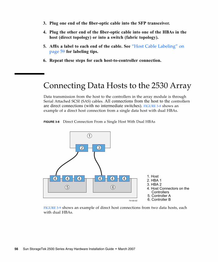
Connecting Data Hosts to the 2530 ArrayData transmission from the host to the controllers in the array module is throughSerial Attached SCSI (SAS) cables. All connections from the host to the controllersare direct connections (with no intermediate switches). FIGURE 3-8 shows anexample of a direct host connection from a single data host with dual HBAs.
FIGURE 3-8 Direct Connection From a Single Host With Dual HBAs
FIGURE 3-9 shows an example of direct host connections from two data hosts, eachwith dual HBAs.
1. Host2. HBA 13. HBA 24. Host Connectors on the
5. Controller A6. Controller B
Controllers
56 Sun StorageTek 2500 Series Array Hardware Installation Guide • March 2007
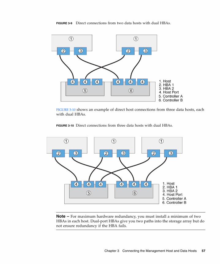
FIGURE 3-9 Direct connections from two data hosts with dual HBAs.
FIGURE 3-10 shows an example of direct host connections from three data hosts, eachwith dual HBAs.
FIGURE 3-10 Direct connections from three data hosts with dual HBAs.
Note – For maximum hardware redundancy, you must install a minimum of twoHBAs in each host. Dual-port HBAs give you two paths into the storage array but donot ensure redundancy if the HBA fails.
Chapter 3 Connecting the Management Host and Data Hosts 57
Before you connect data hosts directly to the array, check that the followingprerequisites have been met:
■ Interface cables are connected and between the HBAs and the array controllers.
■ SAS cables (1-, 3-, or 6-meters) are available to connect the array host ports to thedata host HBAs.
Each controller module on a controller tray has three SAS host ports (FIGURE 3-11).
FIGURE 3-11 SAS Data Host Ports (on back of tray).
▼ To Connect Data Hosts to a 2530 Array1. Locate the host ports at the back of the controller tray (FIGURE 3-11).
If the host port has a plastic protection plug, remove it.
2. Connect one end of the SAS cable to a host port on a controller module.
Host ports are numbered from left to right: host port 1, host port 2, and hostport 3.
3. Connect the other end of each SAS cable to a data host HBA.
4. Affix a label to each end of the cable. See “Host Cable Labeling” on page 59 forinformation about cable labels.
5. Repeat these steps for each host-to-controller connection.
Controller BController A
1. SAS Host Port 12. SAS Host Port 23. SAS Host Port 3
Link Link
HOST1
SAS
LinkLink LinkLink
HOST2 3
SAS
Link Link
DRIVE EXPANSIONSAS
Link Link
HOST1
SAS
LinkLink LinkLink
HOST2 3
SAS
Link Link
DRIVE EXPANSIONSAS
1 12 23 3
58 Sun StorageTek 2500 Series Array Hardware Installation Guide • March 2007
Host Cable LabelingLabels for host cabling identify which host HBA ports and which controller portsyou use when you attach cables between the host and the controller. Cable labels areuseful if you need to disconnect cables to service a controller. Attach a label to eachend of the cable. Use this design to create labels for host cables:
■ Host name and HBA port
■ Controller ID (for example, Controller A)
■ Host channel ID (for example, Host channel 1)
Example Label AbbreviationIn this example, the storage configuration has the following characteristics:
■ Host name is “Engineering”
■ Host HBA 1, port 1
■ Controller A, channel 1
Using this design, the label includes the following information:
Heng-HBA1/P1, CtA-Hch1
Next StepsAfter you connected the management and data hosts, you can power on the trays, asdescribed in Chapter 4.
Chapter 3 Connecting the Management Host and Data Hosts 59

60 Sun StorageTek 2500 Series Array Hardware Installation Guide • March 2007
CHAPTER 4
Powering On the Array
This chapter describes initial tray power-on procedures. Perform the followingprocedures in the order listed:
■ “Before Powering On” on page 61
■ “Powering On the Array” on page 62
■ “Powering Off the Array” on page 63
■ “Next Steps” on page 64
Before Powering OnYou can set up a Dynamic Host Configuration Protocol (DHCP) server to issue the IPaddress to each controller. If a DHCP server is not available, the controller traydefaults to internal static IP addresses. (See the Sun StorageTek Common ArrayManager Software Installation Guide for information about configuring IP addresses onarray controllers.)
For instructions on configuring IP addresses on the array controllers, see“Configuring the IP Address of the Array Controllers” on page 74. For instructionson how to set up the DHCP server, see “Configuring a DHCP Server” on page 81.
61
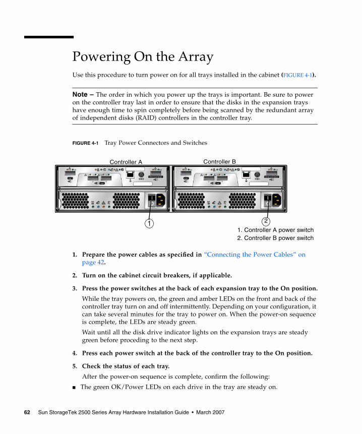
Powering On the ArrayUse this procedure to turn power on for all trays installed in the cabinet (FIGURE 4-1).
Note – The order in which you power up the trays is important. Be sure to poweron the controller tray last in order to ensure that the disks in the expansion trayshave enough time to spin completely before being scanned by the redundant arrayof independent disks (RAID) controllers in the controller tray.
FIGURE 4-1 Tray Power Connectors and Switches
1. Prepare the power cables as specified in “Connecting the Power Cables” onpage 42.
2. Turn on the cabinet circuit breakers, if applicable.
3. Press the power switches at the back of each expansion tray to the On position.
While the tray powers on, the green and amber LEDs on the front and back of thecontroller tray turn on and off intermittently. Depending on your configuration, itcan take several minutes for the tray to power on. When the power-on sequenceis complete, the LEDs are steady green.
Wait until all the disk drive indicator lights on the expansion trays are steadygreen before proceding to the next step.
4. Press each power switch at the back of the controller tray to the On position.
5. Check the status of each tray.
After the power-on sequence is complete, confirm the following:
■ The green OK/Power LEDs on each drive in the tray are steady on.
Controller BController A
1. Controller A power switch2. Controller B power switch
1 2
62 Sun StorageTek 2500 Series Array Hardware Installation Guide • March 2007
■ The green OK/Power LED on the tray is steady on.
If all tray and drive Ok/Power LEDs are steady green and the amber ServiceRequired LEDs are off, the power-on sequence is complete and no faults havebeen detected.
Powering Off the ArrayThe array rarely needs to be powered off. You remove power only when you plan tophysically move the array to another location or are adding additional trays to acontroller.
To power off the array, do the following:
1. Stop all I/O from the hosts, if connected, to the storage system.
2. Wait approximately 2 minutes until all disk drive LEDs have stopped flashing.
Note – If Disk Scrubbing is enabled, the disk drive LEDs will continue to flash afterthe 2-minute period has elapsed. By waiting the 2-minute period, you ensure thatthe data residing in cache has been written to disk. The LED flash rate during diskscrubbing (slow, periodic blink) is different from the flash rate of I/O (fast, random).
After the 2-minute period, data residing in cache is written to disk and thebattery mechanisms are disengaged.
3. Check the Cache Active LED on the controller (FIGURE 1-10) to determine if anyoutstanding cache needs to be written.
If the LED is on, there is still data that needs to be flushed and written to disk.
4. Ensure that the Cache Active LED is no longer flashing before powering off thearray.
5. Press each power switch at the back of the controller tray to the Off position.
6. Press the power switches at the back of each expansion tray to the Off position.
Chapter 4 Powering On the Array 63
Next StepsAfter you have connected the management host and data hosts, you are ready toinstall the management host software as described in the Sun StorageTek CommonArray Manager Software Installation Guide and the data host software as described inChapter 5.
64 Sun StorageTek 2500 Series Array Hardware Installation Guide • March 2007
CHAPTER 5
Data Hosts, HBAs, and OtherSoftware
This chapter describes how to install data host software, HBAs, and other softwareon different host platforms. It contains the following sections:
■ “Data Host Software” on page 65
■ “Setting Up a Data Host On a Solaris System” on page 66
■ “Installing Data Host Software for Operating Systems Other Than Solaris” onpage 69
■ “Enabling Multipathing Software” on page 70
■ “Next Steps” on page 71
Data Host SoftwareThe data host software contains tools that manage the data path I/O connectionsbetween the data host and the array. This includes drivers and utilities that enablearray management hosts to connect to, monitor, and transfer data in a storage areanetwork (SAN).
Note – Some management hosts can also be used as data hosts.
HBAs and DriversA Host Bus Adapter (HBA) is a network interface card that manages all data I/O onyour data host. The specific HBAs you need depend on the data host serverplatform, operating system, data transport (SAS or FC), and data transfer rates used
65
in your storage area network. HBAs must be ordered separately, from Sun or theirrespective manufacturers. Sun HBAs can be ordered from:/www.sun.com/storagetek/storage_networking/hba/
The required versions of HBAdrivers must be installed on the data host before youcan set up a data host. The Sun StorageTek 2500 Series Array Release Notes lists thedata host requirements for HBAs and drivers. Refer to the specific vendor HBAdocumentation for instructions on installing HBA drivers.
MultipathingData host software controls the data path between the data host and the array. Sincethere can be more than one path between the host and the array for redundancy, thisfunction is called multipathing.
You must install data host software (including multipathing) on each data host thatcommunicates with the Sun StorageTek 2500 Series Array. The multipathingsoftware you need depends on the host platform, HBA, and the data transport (SASor FC) in your storage area network. This information is listed in the latest version ofthe Sun StorageTek 2500 Series Array Release Notes.
Setting Up a Data Host On a SolarisSystemThe Sun StorageTek 2500 Series Array provides data path support for data hostsrunning Solaris, Windows 2000, Windows Server 2003, Red Hat Linux, HP-UX,NetWare, and IBM AIX operating systems. This section applies to hosts runningSolaris OS 8, 9, and 10.
See the Sun StorageTek 2500 Series Array Release Notes for the latest supportedoperating system versions.
Note – To install data host software on systems that are not running the Solaris OS, see“Installing Data Host Software for Operating Systems Other Than Solaris” onpage 69.
You must install data host software (including multipathing) on each data host thatcommunicates with the Sun StorageTek 2500 Series Array. Multipathing is includedin the Solaris 10 OS. For Solaris OS 8 and 9 data hosts, you need the SANFoundation Kit software (which includes the multipathing software).
66 Sun StorageTek 2500 Series Array Hardware Installation Guide • March 2007
To install data host software on Solaris OSs, see the following sections:
■ “To Obtain Sun Solaris 8 and 9 Data Host Software” on page 67
■ “To Install the SAN 4.4 Data Host Software” on page 67
▼ To Obtain Sun Solaris 8 and 9 Data HostSoftwareObtain Sun Solaris OS 8 and 9 data host software as follows:
1. Go to the Sun Microsystems web page (sun.com).
The Sun home page is displayed.
2. Select Downloads from the home page navigation bar.
The Downloads page is displayed (it is not labeled).
3. On the View by Category tab, select System Administration>StorageManagement.
The Storage Management page is displayed, showing a list of downloadablestorage-related products.
4. Select the SAN 4.4 product.
The login page is displayed.
5. Login using your Sun account ID.
The SAN 4.4.x Download page is displayed.
6. Accept the License Agreement and select the SAN 4.4 version required for youroperating system.
The data host software version you need depends on your operating system. Seethe Sun StorageTek 2500 Series Array Release Notes for the current data hostsoftware requirements. Download the Solaris x (8 or 9) Base Package (if you donot already have it installed), and then the Install_it Script SAN 4.4.x version asrecommended in the release notes.
There is a README file available on the SAN 4.4.x Download page withinstructions for unpacking and installing the download file on your data hostcomputer.
▼ To Install the SAN 4.4 Data Host SoftwareTo launch the host software installer:
Chapter 5 Data Hosts, HBAs, and Other Software 67

1. Log in to the host as root.
2. Change to the SAN_4.4.xx_install_it directory in which the compressedinstallation file was unpacked:
cd <user-specified location>/SAN_4.4.xx_install_it
3. where xx is the software version number of the installed files.Start the hostsoftware installer by typing the following command:
./install_it
When the installation is complete, the root prompt returns.
4. Enable the Sun StorageTek Traffic Manager multipathing software (see“Enabling Multipathing Software” on page 70).
▼ To Obtain Traffic Manager for OperatingSystems Other Than Solaris1. Go to the Sun Microsystems web page (sun.com).
The Sun home page is displayed.
2. Select Downloads from the home page navigation bar.
The Downloads page is displayed (it is not labeled).
3. On the View by Category tab, select System Administration>StorageManagement.
The Storage Management page is displayed, showing a list of downloadablestorage-related products.
4. Scroll down and select the Traffic Manager version for the operating systemyou have.
The login page is displayed.
5. Login using your Sun account ID.
The Traffic Manager product Download page is displayed.
6. Accept the License Agreement and select the Traffic Manager version requiredfor your operating system.
The data host software version you need depends on your operating system. Seethe Sun StorageTek 2500 Series Array Release Notes for the current data hostsoftware requirements.
There is a README file available on the download page with instructions forunpacking and installing the download file on your data host computer.
68 Sun StorageTek 2500 Series Array Hardware Installation Guide • March 2007
Installing Data Host Software forOperating Systems Other Than SolarisTo install data host software for operating systems other than Solaris, see thefollowing sections:
■ “About Data Host Software For Non-Solaris Platforms” on page 69
■ “Downloading and Installing Sun RDAC Software” on page 69
Note – To dowload software from the Sun Download Center, you must register as aSun customer. The first time you click Download to download a software product,click the Register Now link on the Login page, complete the required fields, andclick Register.
About Data Host Software For Non-SolarisPlatformsThe data host software for Red Hat Linux, HP-UX, AIX, and Windows platforms isSun Redundant Dual Array Controller (RDAC), also known as MPP, and is availablefrom the Sun Download Center (SDLC).
See the Sun StorageTek 2500 Series Array Release Notes for a list of supported operatingsystems, patches, and HBAs.
Downloading and Installing Sun RDAC Software
1. To download the latest version of Sun RDAC software (support for Windowsand Linux multipathing), go to:
http://www.sun.com/download/index.jsp
and select Hardware Drivers>Storage.
2. Select the link for the RDAC driver for the Operating System you have.
An RDAC Driver download page is displayed.
3. Click Download.
4. Log in using your SDLC user name and password.
5. Read and accept the license agreement.
Chapter 5 Data Hosts, HBAs, and Other Software 69

6. Select the link for the data host platform that you want to install.
7. Save the install package to a temporary directory.
8. Uncompress and untar the install package.
9. When the download is finished, log out of the SDLC.
A readme file is provided as part of the installation package. To install the software,refer to the readme file for platform-specific instructions.
Enabling Multipathing SoftwareSun StorageTek SAN Foundation software includes the Sun StorageTek TrafficManager multipathing software.
The procedure you use to enable multipathing software depends on the version ofSolaris OS running on the host:
■ “Enabling Multipathing Software for Solaris 8 or 9 OS” on page 70
■ “Enabling Multipathing Software for Solaris 10 OS” on page 71
▼ Enabling Multipathing Software for Solaris 8 or9 OSTo enable the multipathing software on hosts running Solaris OS 8 or 9:
1. Open the /kernel/drv/scsi_vhci.conf file with a text editor.
2. Set mpxio-disable=”no”; in the file.
3. Set load-balance=”round-robin”; in the file.
4. Set auto-failback=”enable”; in the file.
5. Save the updated file.
6. Reboot the host.
70 Sun StorageTek 2500 Series Array Hardware Installation Guide • March 2007
7. Use the cfgadm command to configure HBA paths.
How you configure paths depends on how you are using your arrays in a SAN ordirect attach environment. See the Sun StorageEdge SAN Foundation Software 4.4Configuration Guide (www.sun.com/products-n-solutions/hardware/docs/Network_Storage_Solutions/SAN/san_software/) for informationabout configuring paths.
▼ Enabling Multipathing Software for Solaris 10OSTo enable multipathing software for all Fibre Channel (FC) ports on hosts runningSolaris OS 10:
1. Type the following command:
# stmsboot -e
Note – See the stmsboot(1M) man page for complete details.
You are prompted to confirm the command:
WARNING: This operation will require a reboot.
Do you want to continue ? [y/n] (default: y)
2. Press Return to reboot the host.
Next StepsAfter you have installed and enabled multipathing on the data hosts, configure IPaddressing on the array controllers as described in Chapter 6.
Chapter 5 Data Hosts, HBAs, and Other Software 71

72 Sun StorageTek 2500 Series Array Hardware Installation Guide • March 2007
CHAPTER 6
Configuring IP Addressing
In order for there to be an out-of-band Ethernet connection between the localmanagement host and the array controllers, the management host and the arraycontrollers must have valid IP addresses.
This chapter describes how to configure IP addressing on the local management hostand the array controllers. It contains the following sections:
■ “About IP Addressing” on page 73
■ “Configuring the IP Address of the Array Controllers” on page 74
About IP AddressingThe Sun StorageTek 2500 Series Array is managed out-of-band by way of a standardEthernet connection between the redundant array of independent disk (RAID)controllers and your management host.
Perform the following procedures to ensure that the local management host and thearray controllers have valid IP addresses:
■ Configure IP addresses for the array controllers (see “Configuring the IP Addressof the Array Controllers” on page 74)
■ Configure an IP address for the management host (see the Sun StorageTek CommonArray Manager Software Installation Guide)
73
Configuring the IP Address of the ArrayControllersYou can configure two types of IP addressing for the Ethernet port of each arraycontroller:
■ Dynamic Host Configuration Protocol (DHCP) IP addressing – IP addresses forthe Ethernet port are assigned dynamically from a DHCP server runningbootstrap protocol (BOOTP) services. An IP address assigned to an Ethernet portis held only as long as needed. By default, DHCP is not enabled at initial power-on, so you must connect to it using a serial console or the Common ArrayManager and the controller’s static IP address, and then enable DHCP.
■ Static IP Addressing – You assign a specific IP address to the Ethernet port of eachcontroller. Static IP addresses remain in effect until you modify or remove them oryou change the method of IP addressing for the Ethernet port to DHCP.
By default, if the array controllers cannot find a DHCP server upon initial power-on, an internal IP address is assigned to Ethernet port 1 of each controller:
■ The Ethernet port of Controller A is assigned IP address 192.168.128.101
■ The Ethernet port of Controller B is assigned IP address 192.168.128.102
■ The default subnet mask for each port is 255.255.255.0
To configure the Ethernet port on a controller with either dynamic or static IPaddressing, see one of the following sections:
■ “Configuring Dynamic (DHCP) IP Addressing” on page 74
■ “Configuring Static IP Addressing” on page 75
Configuring Dynamic (DHCP) IP AddressingIf BOOTP services are available on the DHCP server at initial array power on, thisserver assigns a dynamic IP address for the Ethernet port on each controller.
If a DHCP server is not available, the controller tray defaults to internal static IPaddresses as described in “Configuring the IP Address of the Array Controllers” onpage 74.
If you want to set up a DHCP server, refer to Appendix A for a description of how toconfigure BOOTP services in Sun Solaris or Microsoft Windows environments.
You can restore DHCP IP addressing to Ethernet port 1 of either controller in eitherof three ways:
■ Start a DHCP server on the same subnet, then reboot the 2500 Series Array.
74 Sun StorageTek 2500 Series Array Hardware Installation Guide • March 2007
■ Using the serial port interface (see “Using the Serial Port Interface to Assign IPAddresses” on page 75)
■ Using the Sun StorageTek Common Array Manager (see the Sun StorageTekCommon Array Manager Software Installation Guide)
Configuring Static IP AddressingThere are two methods of assigning static IP addresses to the Ethernet ports of acontroller:
■ The serial port interface (see “Using the Serial Port Interface to Assign IPAddresses” on page 75)
■ The Common Array Manager (see the Sun StorageTek Common Array ManagerSoftware Installation Guide)
Note – It is recommended that you use the serial port interface to assign IPaddresses to the Ethernet port of each controller, if possible.
Using the Serial Port Interface to Assign IP Addresses
You can use the serial port interface on a controller to set the IP address for theEthernet port on the controller.
To use the serial port interface to configure IP addressing for the Ethernet port ofeach controller, you must complete the tasks described in the following sections:
■ “To Connect a Terminal to the Serial Port” on page 75
■ “To Set Up the Terminal Emulation Program” on page 76
■ “To Establish a Connection With the Serial Port” on page 77
■ “To Configure the IP Addresses” on page 78
▼ To Connect a Terminal to the Serial Port
You will establish a serial connection to each controller, Controller A and ControllerB. Two mini-DIN to RJ45 serial port cables are supplied with each controller tray.
Chapter 6 Configuring IP Addressing 75

To connect a terminal to the serial port of a controller:
1. Connect the 6-pin mini-DIN connector of the serial cable to the serial portconnector (diagnostic port) on the controller (FIGURE 1-3 on page 6).
2. Connect the RJ-45 connector of the serial cable to the serial port connector onthe terminal. It may be necessary to use an RJ45-DB9 adapter between theserial cable RJ-45 connector and the serial port of the terminal.
3. For PC and laptop serial connections, you will also need to use a null modem.Connect the null modem between the serial cable or RJ45-DB9 adapter and thePC serial port.
Note – If your PC does not have a serial port, you can use a USB–Serial Port adapter(separately available from third-party vendors; not included with 2500 Series Arrayship kits).
Serial Cable Pinouts
TABLE 6-1 shows the pinouts for the RJ45-DIN serial cable (Sun part number 530-3544) included with the 2500 Series Array shipkit.
▼ To Set Up the Terminal Emulation Program
To set up a terminal emulation program to connect to the serial port:
1. Select VT100 emulation.
2. Remove any modem strings from the connection profile.
3. Set up the connection profile with the following communication settings:
TABLE 6-1 RJ45 to DIN Serial Cable Pinouts
RJ45 ----------> PS2-miniDin
1 Tx 6 Rx
2
3 Rx 1 Rx
4,5,7 3, 5 GRD
6 Rx 2 Tx
8 4
76 Sun StorageTek 2500 Series Array Hardware Installation Guide • March 2007
■ Data Rate: 38400
■ Data Bits: 8
■ Parity: None
■ Stop Bits: 1
■ Flow Control: None
▼ To Establish a Connection With the Serial Port
To establish a connection with the serial port and display the Service Interface menu:
1. Press Break.
Note – The array serial port requires that the break character be received. Use theappropriate escape sequence for your terminal setup to send the required breakcharacter to the array controller, For example, you generate the Break character onsome terminals by pressing the Control and Break keys simultaneously.
The serial port responds with a request to synchronize with the baud rate of theterminal:
Set baud rate: press <space> within 5 seconds
2. Press the space bar within five seconds.
The serial port confirms the established baud rate for the connection:
Baud rate set to 38400
3. Press Break (see Note above)
The serial port responds with the following message:
Press within 5 seconds: <S> for Service Interface, <BREAK>for baud rate
4. Press S to access the Service Interface menu.
Note – Send Break to synchronize the serial port to a different terminal port rate(see Note above).
The serial port requests the serial port password:
Enter Password to access Service Interface (60 sec timeout):
->
5. Type the serial port password, kra16wen, and press Enter.
The Service Interface menu is displayed.
Chapter 6 Configuring IP Addressing 77
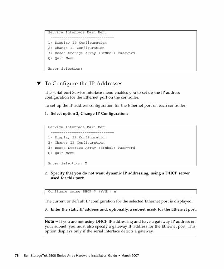
▼ To Configure the IP Addresses
The serial port Service Interface menu enables you to set up the IP addressconfiguration for the Ethernet port on the controller.
To set up the IP address configuration for the Ethernet port on each controller:
1. Select option 2, Change IP Configuration:
2. Specify that you do not want dynamic IP addressing, using a DHCP server,used for this port:
The current or default IP configuration for the selected Ethernet port is displayed.
3. Enter the static IP address and, optionally, a subnet mask for the Ethernet port:
Note – If you are not using DHCP IP addressing and have a gateway IP address onyour subnet, you must also specify a gateway IP address for the Ethernet port. Thisoption displays only if the serial interface detects a gateway.
Service Interface Main Menu
==============================
1) Display IP Configuration
2) Change IP Configuration
3) Reset Storage Array (SYMbol) Password
Q) Quit Menu
Enter Selection:
Service Interface Main Menu
==============================
1) Display IP Configuration
2) Change IP Configuration
3) Reset Storage Array (SYMbol) Password
Q) Quit Menu
Enter Selection: 2
Configure using DHCP ? (Y/N): n
78 Sun StorageTek 2500 Series Array Hardware Installation Guide • March 2007
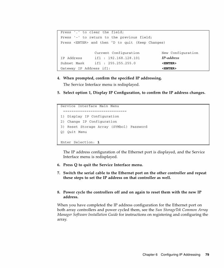
4. When prompted, confirm the specified IP addressing.
The Service Interface menu is redisplayed.
5. Select option 1, Display IP Configuration, to confirm the IP address changes.
The IP address configuration of the Ethernet port is displayed, and the ServiceInterface menu is redisplayed.
6. Press Q to quit the Service Interface menu.
7. Switch the serial cable to the Ethernet port on the other controller and repeatthese steps to set the IP address on that controller as well.
8. Power cycle the controllers off and on again to reset them with the new IPaddress.
When you have completed the IP address configuration for the Ethernet port onboth array controllers and power cycled them, see the Sun StorageTek Common ArrayManager Software Installation Guide for instructions on registering and configuring thearray.
Press '.' to clear the field;
Press '-' to return to the previous field;
Press <ENTER> and then ^D to quit (Keep Changes)
Current Configuration New Configuration
IP Address if1 : 192.168.128.101 IP-addressSubnet Mask if1 : 255.255.255.0 <ENTER>
Gateway IP Address if1: <ENTER>
Service Interface Main Menu
==============================
1) Display IP Configuration
2) Change IP Configuration
3) Reset Storage Array (SYMbol) Password
Q) Quit Menu
Enter Selection: 1
Chapter 6 Configuring IP Addressing 79

80 Sun StorageTek 2500 Series Array Hardware Installation Guide • March 2007
CHAPTER A
Configuring a DHCP Server
This appendix describes how to configure bootstrap protocol (BOOTP) services in aSun Solaris and Microsoft Windows environment. It contains the following sections:
■ “Before You Begin” on page 81
■ “Setting Up a Solaris DHCP Server” on page 81
■ “Setting Up a Windows 2000 Advanced Server” on page 86
Dynamic IP addresses are assigned through dynamic host control protocol (DHCP)server BOOTP services.
Before You BeginYou need each controller’s media access control (MAC) address to configure theDHCP server. The MAC address is located on the bar code label at the back of eachredundant array of independent disks (RAID) controller. Since there are twocontrollers per array, you need two MAC addresses.
Setting Up a Solaris DHCP ServerThe following procedure provides an example of how to set up a DHCP server withthe BOOTP option for the Solaris 8, 9, and 10 Operating Systems. Your environmentmay require different steps.
1. Modify the netmasks line of the /etc/nsswitch.conf file as shown here:#netmasks: nis [NOTFOUND=return] filesnetmasks: files nis [NOTFOUND=return]
81
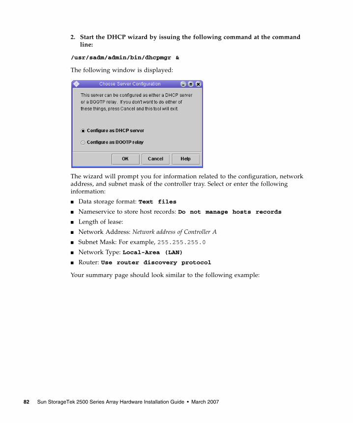
2. Start the DHCP wizard by issuing the following command at the commandline:
/usr/sadm/admin/bin/dhcpmgr &
The following window is displayed:
The wizard will prompt you for information related to the configuration, networkaddress, and subnet mask of the controller tray. Select or enter the followinginformation:
■ Data storage format: Text files
■ Nameservice to store host records: Do not manage hosts records
■ Length of lease:
■ Network Address: Network address of Controller A
■ Subnet Mask: For example, 255.255.255.0
■ Network Type: Local-Area (LAN)
■ Router: Use router discovery protocol
Your summary page should look similar to the following example:
82 Sun StorageTek 2500 Series Array Hardware Installation Guide • March 2007
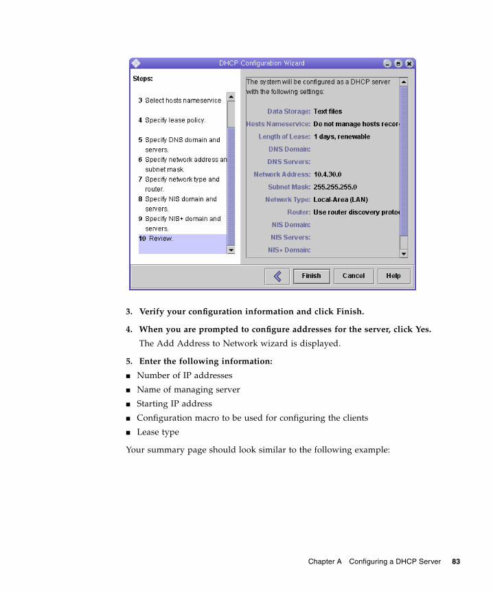
3. Verify your configuration information and click Finish.
4. When you are prompted to configure addresses for the server, click Yes.
The Add Address to Network wizard is displayed.
5. Enter the following information:
■ Number of IP addresses
■ Name of managing server
■ Starting IP address
■ Configuration macro to be used for configuring the clients
■ Lease type
Your summary page should look similar to the following example:
Chapter A Configuring a DHCP Server 83
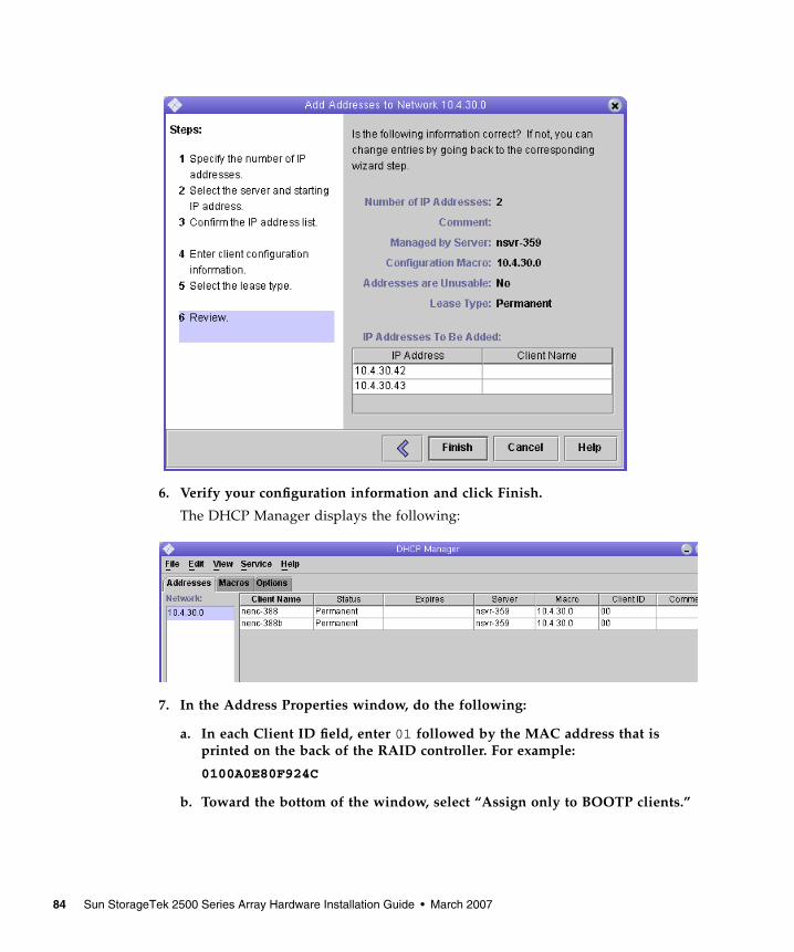
6. Verify your configuration information and click Finish.
The DHCP Manager displays the following:
7. In the Address Properties window, do the following:
a. In each Client ID field, enter 01 followed by the MAC address that isprinted on the back of the RAID controller. For example:
0100A0E80F924C
b. Toward the bottom of the window, select “Assign only to BOOTP clients.”
84 Sun StorageTek 2500 Series Array Hardware Installation Guide • March 2007
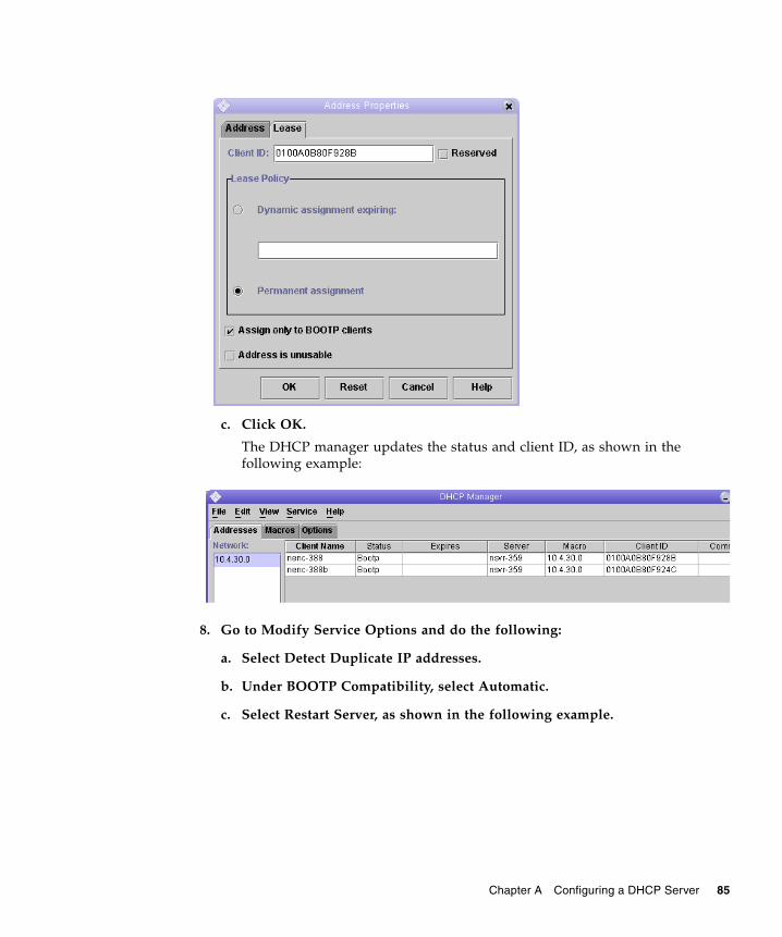
c. Click OK.
The DHCP manager updates the status and client ID, as shown in thefollowing example:
8. Go to Modify Service Options and do the following:
a. Select Detect Duplicate IP addresses.
b. Under BOOTP Compatibility, select Automatic.
c. Select Restart Server, as shown in the following example.
Chapter A Configuring a DHCP Server 85
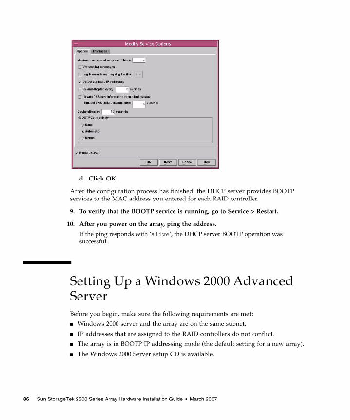
d. Click OK.
After the configuration process has finished, the DHCP server provides BOOTPservices to the MAC address you entered for each RAID controller.
9. To verify that the BOOTP service is running, go to Service > Restart.
10. After you power on the array, ping the address.
If the ping responds with ‘alive’, the DHCP server BOOTP operation wassuccessful.
Setting Up a Windows 2000 AdvancedServerBefore you begin, make sure the following requirements are met:
■ Windows 2000 server and the array are on the same subnet.
■ IP addresses that are assigned to the RAID controllers do not conflict.
■ The array is in BOOTP IP addressing mode (the default setting for a new array).
■ The Windows 2000 Server setup CD is available.
86 Sun StorageTek 2500 Series Array Hardware Installation Guide • March 2007
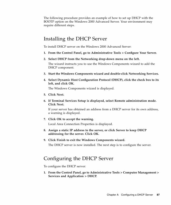
The following procedure provides an example of how to set up DHCP with theBOOTP option on the Windows 2000 Advanced Server. Your environment mayrequire different steps.
Installing the DHCP ServerTo install DHCP server on the Windows 2000 Advanced Server:
1. From the Control Panel, go to Administrative Tools > Configure Your Server.
2. Select DHCP from the Networking drop-down menu on the left.
The wizard instructs you to use the Windows Components wizard to add theDHCP component.
3. Start the Windows Components wizard and double-click Networking Services.
4. Select Dynamic Host Configuration Protocol (DHCP), click the check box to itsleft, and click OK.
The Windows Components wizard is displayed.
5. Click Next.
6. If Terminal Services Setup is displayed, select Remote administration mode.Click Next.
If your server has obtained an address from a DHCP server for its own address,a warning is displayed.
7. Click OK to accept the warning.
Local Area Connection Properties is displayed.
8. Assign a static IP address to the server, or click Server to keep DHCPaddressing for the server. Click OK.
9. Click Finish to exit the Windows Components wizard.
The DHCP server is now installed. The next step is to configure the server.
Configuring the DHCP ServerTo configure the DHCP server:
1. From the Control Panel, go to Administrative Tools > Computer Management >Services and Application > DHCP.
Chapter A Configuring a DHCP Server 87
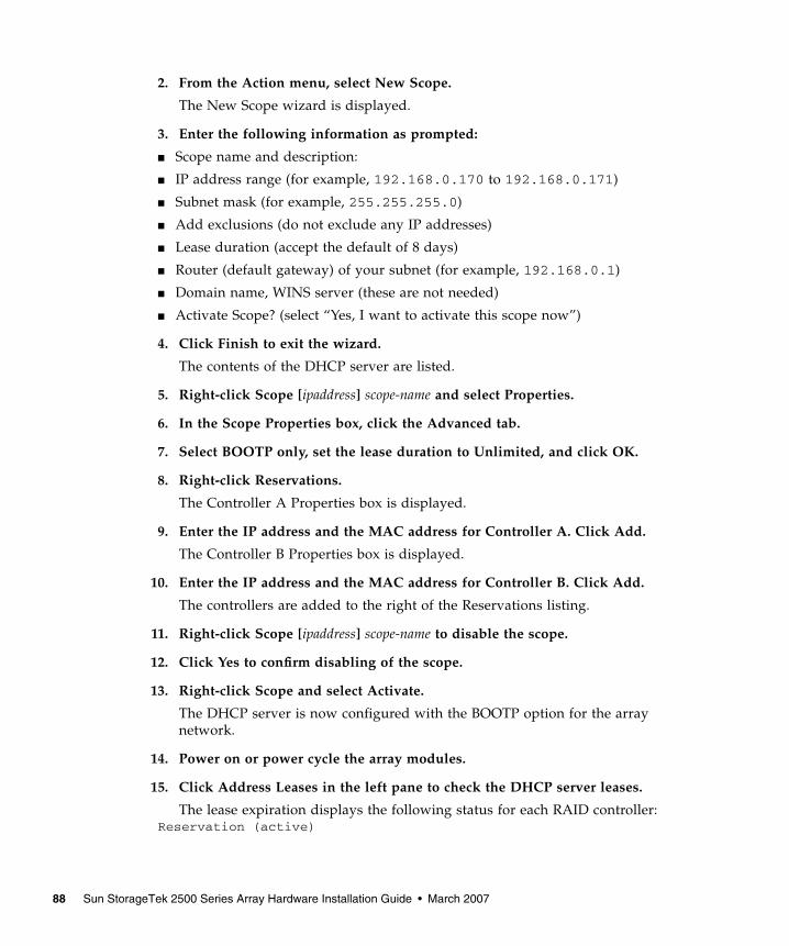
2. From the Action menu, select New Scope.
The New Scope wizard is displayed.
3. Enter the following information as prompted:
■ Scope name and description:
■ IP address range (for example, 192.168.0.170 to 192.168.0.171)
■ Subnet mask (for example, 255.255.255.0)
■ Add exclusions (do not exclude any IP addresses)
■ Lease duration (accept the default of 8 days)
■ Router (default gateway) of your subnet (for example, 192.168.0.1)
■ Domain name, WINS server (these are not needed)
■ Activate Scope? (select “Yes, I want to activate this scope now”)
4. Click Finish to exit the wizard.
The contents of the DHCP server are listed.
5. Right-click Scope [ipaddress] scope-name and select Properties.
6. In the Scope Properties box, click the Advanced tab.
7. Select BOOTP only, set the lease duration to Unlimited, and click OK.
8. Right-click Reservations.
The Controller A Properties box is displayed.
9. Enter the IP address and the MAC address for Controller A. Click Add.
The Controller B Properties box is displayed.
10. Enter the IP address and the MAC address for Controller B. Click Add.
The controllers are added to the right of the Reservations listing.
11. Right-click Scope [ipaddress] scope-name to disable the scope.
12. Click Yes to confirm disabling of the scope.
13. Right-click Scope and select Activate.
The DHCP server is now configured with the BOOTP option for the arraynetwork.
14. Power on or power cycle the array modules.
15. Click Address Leases in the left pane to check the DHCP server leases.
The lease expiration displays the following status for each RAID controller:Reservation (active)
88 Sun StorageTek 2500 Series Array Hardware Installation Guide • March 2007
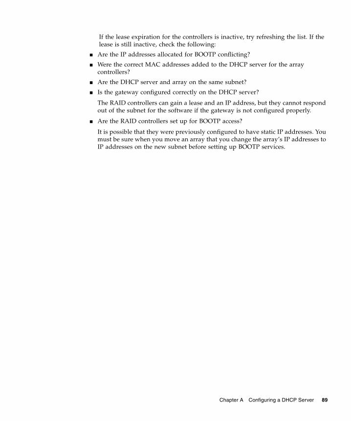
If the lease expiration for the controllers is inactive, try refreshing the list. If thelease is still inactive, check the following:
■ Are the IP addresses allocated for BOOTP conflicting?
■ Were the correct MAC addresses added to the DHCP server for the arraycontrollers?
■ Are the DHCP server and array on the same subnet?
■ Is the gateway configured correctly on the DHCP server?
The RAID controllers can gain a lease and an IP address, but they cannot respondout of the subnet for the software if the gateway is not configured properly.
■ Are the RAID controllers set up for BOOTP access?
It is possible that they were previously configured to have static IP addresses. Youmust be sure when you move an array that you change the array’s IP addresses toIP addresses on the new subnet before setting up BOOTP services.
Chapter A Configuring a DHCP Server 89

90 Sun StorageTek 2500 Series Array Hardware Installation Guide • March 2007
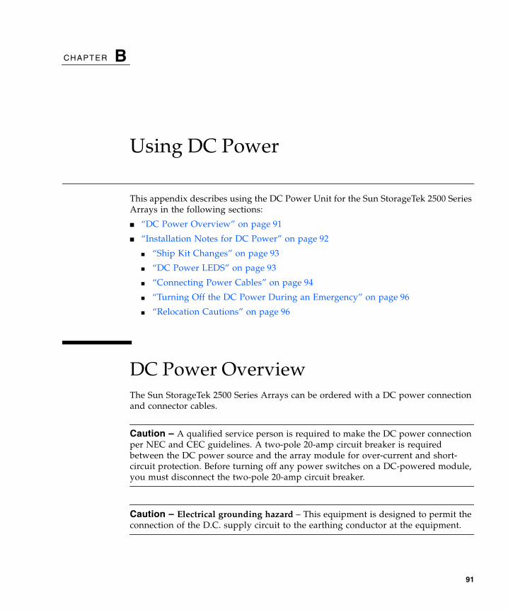
CHAPTER B
Using DC Power
This appendix describes using the DC Power Unit for the Sun StorageTek 2500 SeriesArrays in the following sections:
■ “DC Power Overview” on page 91
■ “Installation Notes for DC Power” on page 92
■ “Ship Kit Changes” on page 93
■ “DC Power LEDS” on page 93
■ “Connecting Power Cables” on page 94
■ “Turning Off the DC Power During an Emergency” on page 96
■ “Relocation Cautions” on page 96
DC Power OverviewThe Sun StorageTek 2500 Series Arrays can be ordered with a DC power connectionand connector cables.
Caution – A qualified service person is required to make the DC power connectionper NEC and CEC guidelines. A two-pole 20-amp circuit breaker is requiredbetween the DC power source and the array module for over-current and short-circuit protection. Before turning off any power switches on a DC-powered module,you must disconnect the two-pole 20-amp circuit breaker.
Caution – Electrical grounding hazard – This equipment is designed to permit theconnection of the D.C. supply circuit to the earthing conductor at the equipment.
91
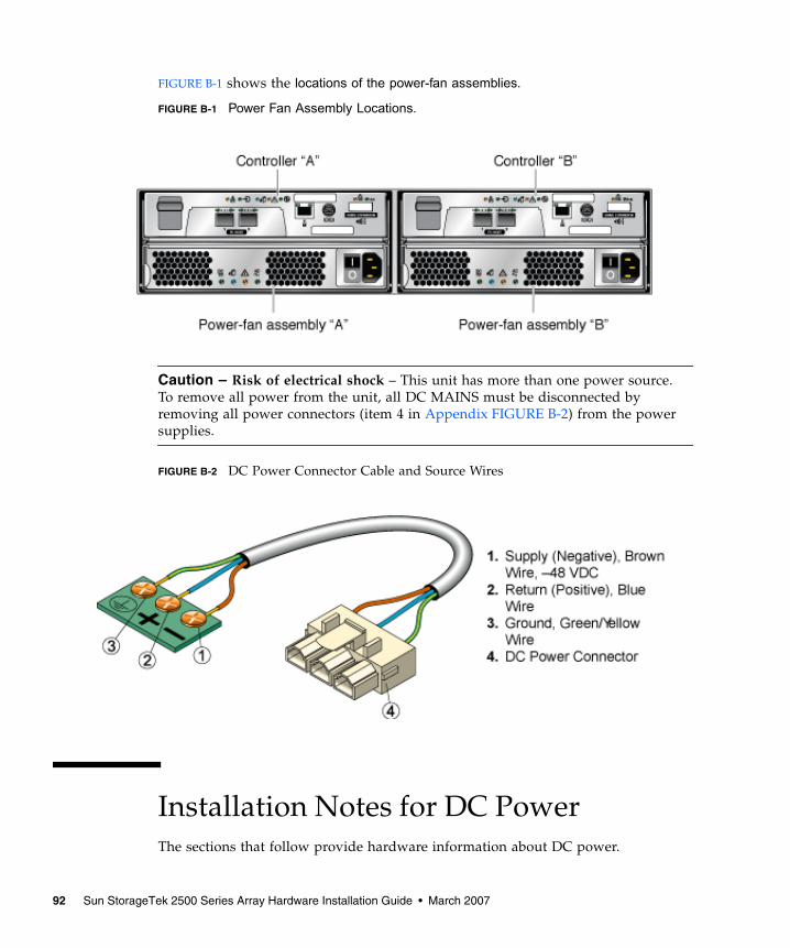
FIGURE B-1 shows the locations of the power-fan assemblies.
FIGURE B-1 Power Fan Assembly Locations.
Caution – Risk of electrical shock – This unit has more than one power source.To remove all power from the unit, all DC MAINS must be disconnected byremoving all power connectors (item 4 in Appendix FIGURE B-2) from the powersupplies.
FIGURE B-2 DC Power Connector Cable and Source Wires
Installation Notes for DC PowerThe sections that follow provide hardware information about DC power.
92 Sun StorageTek 2500 Series Array Hardware Installation Guide • March 2007

■ “Ship Kit Changes” on page 93
■ “DC Power LEDS” on page 93
■ “Connecting Power Cables” on page 94
■ “Turning Off the DC Power During an Emergency” on page 96
■ “Relocation Cautions” on page 96
Ship Kit ChangesIf the DC power option is ordered, two DC power connector cables are providedwith each controller tray for connection to centralized DC power plant equipment.
Caution – A qualified service person is required to make the DC power connectionper NEC and CEC guidelines. A two-pole 20-amp circuit breaker is requiredbetween the DC power source and the array module for over-current and short-circuit protection. Before turning off any power switches on a DC-powered module,you must disconnect the two-pole 20-amp circuit breaker.
DC Power LEDSFIGURE B-3 shows the LEDs, on/off power switch, and power cable receptacle on theback of the DC power module.
FIGURE B-3 DC Power Module LEDs, Power Switch, and Power Cable Receptacle.
Chapter B Using DC Power 93
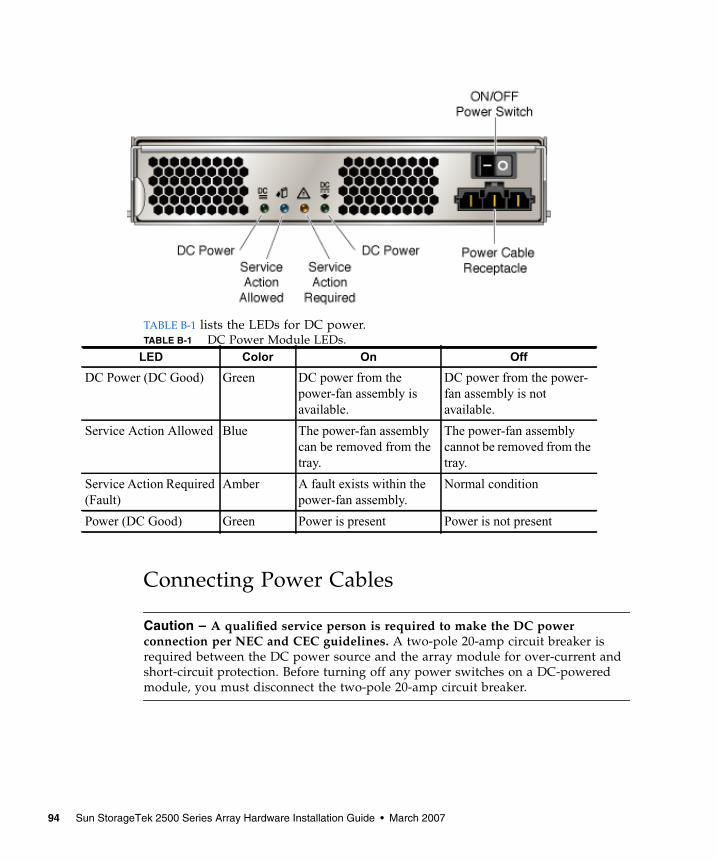
TABLE B-1 lists the LEDs for DC power.TABLE B-1 DC Power Module LEDs.
Connecting Power Cables
Caution – A qualified service person is required to make the DC powerconnection per NEC and CEC guidelines. A two-pole 20-amp circuit breaker isrequired between the DC power source and the array module for over-current andshort-circuit protection. Before turning off any power switches on a DC-poweredmodule, you must disconnect the two-pole 20-amp circuit breaker.
LED Color On Off
DC Power (DC Good) Green DC power from thepower-fan assembly isavailable.
DC power from the power-fan assembly is notavailable.
Service Action Allowed Blue The power-fan assemblycan be removed from thetray.
The power-fan assemblycannot be removed from thetray.
Service Action Required(Fault)
Amber A fault exists within thepower-fan assembly.
Normal condition
Power (DC Good) Green Power is present Power is not present
94 Sun StorageTek 2500 Series Array Hardware Installation Guide • March 2007
Caution – Ensure that you do not turn on power to the array module or theconnected drive modules until this guide instructs you to do so. For the properprocedure for turning on the power, see ““Connecting Power Cables” on page 94.”
Caution – Electrical grounding hazard – This equipment is designed to permit theconnection of the D.C. supply circuit to the earthing conductor at the equipment.
▼ Connecting the Cables1. Disconnect the two-pole 20-amp DC circuit breaker for the storage array.
2. Ensure that all DC power switches on the DC-powered array module and allDC power switches on any connected, DC-powered drive modules are turnedoff.
3. Connect the DC power connector cable to the DC power connector on the backof the array module.
Caution – The three source wires on the DC power connector cable (–48 VDC)connect the array module to centralized DC power plant equipment, typicallythrough a bus bar located above the cabinet.
4. A qualified service person is required to make the DC power connection perNEC and CEC guidelines. A two-pole 20-amp circuit breaker is requiredbetween the DC power source and DC-powered modules for over-current andshort-circuit protection. Connect the DC power source wires on the other endof the DC power connector cable to the centralized DC power plant equipmentas follows (see “DC Power Connector Cable and Source Wires” on page 92).
a. Connect the brown –48-VDC supply wire to the negative terminal.
b. Connect the blue return wire to the positive terminal.
c. Connect the green/yellow ground wire to the ground terminal.
5. If applicable, connect a DC power cable to each DC-powered expansion tray inthe storage array.
Chapter B Using DC Power 95
Turning Off the DC Power During an Emergency
Caution – Potential loss of data – An emergency shutdown of the storage arraymight not allow the server to complete its I/O to the storage array.
Note – Before turning off the power switches on a DC-powered tray you mustdisconnect the two-pole 20-amp circuit breaker.
Relocation CautionsUse the following guidelines when relocating trays or drives from one storage arrayto another.
Caution – Potential data loss – Moving a array or array components that areconfigured as part of a volume group can result in data loss. To prevent data loss,always consult a Customer Support representative before relocating configureddrives, controller trays or expansion trays.
Note – Trays in arrays can be connected to the DC power supply (–48 VDC). Beforeturning off any power switches on a DC-powered tray, you must disconnect the two-pole 20-amp circuit breaker.
Do not move controller trays or expansion trays that are part of a volume groupconfiguration. If you must move array components, contact a Customer Supportrepresentative for procedures. A Customer Support representative might direct youto complete several tasks prior to undertaking the relocation. These tasks mightinclude:
■ Creating, saving, and printing an array profile of each storage array that isaffected by the relocation of a drive or tray.
■ Performing a complete backup of all data on the drives that you intend to move.
■ Verifying that the volume group and each of its associated volumes on theaffected array have an Optimal status.
■ Determining the location and status of any global hot spares associated with theaffected storage array.
96 Sun StorageTek 2500 Series Array Hardware Installation Guide • March 2007
Glossary
Definitions obtained from the Storage Networking Industry Association (SNIA)Dictionary are indicated with “(SNIA)” at the end. For the complete SNIADictionary, go to www.snia.org/education/dictionary.
A
agent
The component of the system monitoring and diagnostic software that collectshealth and asset information about the array.
alarm
A type of event that requires service action. See also event.
alert
A subtype of an event that requires user intervention. The term actionable event oftendescribes an alert. See also event.
array
Multiple disk drives that function as a single storage device. A high-availability(HA) array configuration has redundant controllers and expansion trays of diskdrives.
array hot-spare
A disk that serves as a hot-spare within an array as part of the storage pool; areserve disk that can be made available to all virtual disks within an array. See alsohot-spare.
97
B
block
The amount of data sent or received by the host per I/O operation; the size of a dataunit.
C
capacity
The amount of storage you must allocate to storage elements, including volumes,pools, and virtual disks. Capacity planning should include allocations for volumesnapshots and volume copies.
CLI
Command-line interface. The SSCS command-line interface is available from theremote CLI client or through an SSCS directory on the Solaris Operating Systemmanagement software station.
controller tray
A tray with an installed redundant RAID controller pair. In a Sun StorageTek 2500Series array, 1x1, 1x2, 1x3, and 1x4 array types are available.
control path
The route used for communication of system management information, usually anout-of-band connection.
customer LAN
See site LAN.
D
DAS
See direct attached storage (DAS).
data host
Any host that uses the system for storage. A data host can be connected directly tothe array (direct attach storage, or DAS) or can be connected to an external switchthat supports multiple data hosts (storage area network, or SAN). See also host.
98 Sun StorageTek 2500 Series Array Hardware Installation Guide • March 2007
data path
The route taken by a data packet between a data host and the storage device.
direct attached storage (DAS)
A storage architecture in which one or two hosts that access data are connectedphysically to a storage array.
disk
A physical drive component that stores data.
E
event
A notification of something that happened on a device. There are many types ofevents, and each type describes a separate occurrence. See also alarm and alert.
expansion tray
A tray that does not have a RAID controller, used to expand the capacity of an array.This type of tray must be attached to a controller tray to function.
extent
A set of contiguous blocks with consecutive logical addresses on a physical orvirtual disk.
F
failover and recovery
The process of changing the data path automatically to an alternate path.
fault coverage
The percentage of faults detected against all possible faults or against all faults of agiven type.
FC
See Fibre Channel (FC).
Fibre Channel (FC)
A set of standards for a serial I/O bus capable of transferring data between twoports at up to 100 megabytes/second, with standards proposals to go to higherspeeds. Fibre Channel supports point to point, arbitrated loop, and switched
Glossary 99
topologies. Fibre Channel was completely developed through industry cooperation,unlike SCSI, which was developed by a vendor and submitted for standardizationafter the fact.
Fibre Channel switch
A networking device that can send packets directly to a port associated with a givennetwork address in a Fibre Channel storage area network (SAN). Fibre Channelswitches are used to expand the number of servers that can connect to a particularstorage port. Each switch is managed by its own management software.
field-replaceable unit (FRU)
An assembly component that is designed to be replaced on site, without the systemhaving to be returned to the manufacturer for repair.
FRU
See field-replaceable unit (FRU).
H
HBA
See host bus adapter (HBA).
host
As a function of the Sun StorageTek 2500 Series array configuration, a representationof a data host that is mapped to initiators and volumes to create a storage domain.See also data host, initiator.
host bus adapter (HBA)
An I/O adapter that connects a host I/O bus to a computer’s memory system.Abbreviated HBA. Host bus adapter is the preferred term in SCSI contexts. Adapterand NIC are the preferred terms in Fibre Channel contexts. The term NIC is used innetworking contexts such as Ethernet and token ring. See also initiator.
host group
A group of hosts with common storage characteristics that can be mapped tovolumes. See also host.
hot-spare
The drive used by a controller to replace a failed disk. See also array hot-spare.
100 Sun StorageTek 2500 Series Array Hardware Installation Guide • March 2007
I
in-band traffic
System management traffic that uses the data path between a host and a storagedevice. See also out-of-band traffic.
initiator
A system component that initiates an I/O operation over a Fibre Channel (FC) network.If allowed by FC fabric zoning rules, each host connection within the FC network has theability to initiate transactions with the storage array. Each host in the FC networkrepresents a separate initiator, so if a host is connected to the system through two hostbus adapters (HBAs), the system identifies two different initiators (similar to multi-homed, Ethernet-based hosts). In contrast, when multipathing is used in round-robinmode, multiple HBAs are grouped together, and the multipathing software identifies thegroup of HBAs as a single initiator.
IOPS
A measure of transaction speed, representing the number of input and outputtransactions per second.
L
LAN
Local area network.
logical unit number (LUN)
The SCSI identifier for a volume as it is recognized by a particular host. The samevolume can be represented by a different LUN to a different host.
LUN
See logical unit number (LUN).
M
MAC address
See media access control (MAC) address.
management host
A Solaris host serving the configuration, management, and monitoring software forthe Sun StorageTek 2500 Series array. The software on the station can be accessedwith a browser to run the browser interface or with a remote scripting command-line interface (CLI) client to access the SSCS CLI commands.
Glossary 101
master / alternate master
A design for reliability that uses redundant configuration. Array configurationsshare master/alternate master configurations: each array configuration has twocontroller trays that are grouped as one host. In each case, the master componentuses the IP address and name. If the master fails, the alternate master assumes the IPaddress and name and takes over the master’s functions.
media access control (MAC) address
The physical address identifying an Ethernet controller board. The MAC address,also called an Ethernet address, is set at the factory and must be mapped to the IPaddress of the device.
mirroring
A form of storage – also called RAID Level 1, independent copy, and real-time copy –whereby two or more independent, identical copies of data are maintained on separatemedia. Typical mirroring technologies enable the cloning of data sets to provideredundancy for a storage system.
multipathing
A design for redundancy that provides at least two physical paths to a target.
N
O
out-of-band traffic
System management traffic outside of the primary data path that uses an Ethernetnetwork. See also in-band traffic.
P
PDU
See power distribution unit (PDU).
pool
See storage pool.
power distribution unit (PDU)
The assembly that provides power management for the system. The redundantdesign uses two PDUs in each system so that the system’s data path continues tofunction if one of the PDUs fails.
102 Sun StorageTek 2500 Series Array Hardware Installation Guide • March 2007
profile
See storage profile.
provisioning
The process of allocation and assignment of storage to hosts.
R
RAID
An acronym for Redundant Array of Independent Disks, a family of techniques formanaging multiple disks to deliver desirable cost, data availability, and performancecharacteristics to host environments. Also, a phrase adopted from the 1988 SIGMODpaper A Case for Redundant Arrays of Inexpensive Disks.
remote monitoring
Monitoring of the functions and performance of a hardware system from a locationother than where the hardware resides.
remote scripting CLI client
A command-line interface (CLI) that enables you to manage the system from a remotemanagement host. The client communicates with the management software through asecure out-of-band interface, HTTPS, and provides the same control and monitoringcapability as the browser interface. The client must be installed on a host that hasnetwork access to the system.
S
SAN
See storage area network (SAN).
site LAN
The local area network at your site. When the system is connected to your LAN, thesystem can be managed through a browser from any host on the LAN.
snapshot
An copy of a volume’s data at a specific point in time.
SSCS
Sun Storage Command System. The command-line interface (CLI) that can be usedto manage the array.
Glossary 103
storage area network (SAN)
An architecture in which the storage elements are connected to each other and to a serverthat is the access point for all systems that use the SAN to store data.
storage domain
A secure container that holds a subset of the system’s total storage resources. Multiplestorage domains can be created to securely partition the system’s total set of storageresources. This enables you to organize multiple departments or applications into a singlestorage management infrastructure.
storage pool
A container that groups physical disk capacity (abstracted as virtual disks in thebrowser interface) into a logical pool of available storage capacity. A storage pool’scharacteristics are defined by a storage profile. You can create multiple storage poolsto segregate storage capacity for use in various types of applications (for example,high throughput and online transaction-processing applications).
storage profile
A defined set of storage performance characteristics such as RAID level, segment size,dedicated hot-spare, and virtualization strategy. You can choose a predefined profilesuitable for the application that is using the storage, or you can create a custom profile.
storage tray
An enclosure containing disks. A tray with dual RAID controllers is called acontroller tray; a tray without controllers is called an expansion tray.
stripe size
The number of blocks in a stripe. A striped array’s stripe size is the stripe depthmultiplied by the number of member extents. A parity RAID array’s stripe size is thestripe depth multiplied by one less than the number of member extents. See alsostriping.
striping
Short for data striping; also known as RAID Level 0 or RAID 0. A mapping technique inwhich fixed-size consecutive ranges of virtual disk data addresses are mapped tosuccessive array members in a cyclic pattern. (SNIA).
T
target
The system component that receives a SCSI I/O command. (SNIA).
104 Sun StorageTek 2500 Series Array Hardware Installation Guide • March 2007
thin-scripting client
See remote scripting CLI client.
tray
See storage tray.
U
V
virtual disk
A set of disk blocks presented to an operating environment as a range ofconsecutively numbered logical blocks with disk-like storage and I/O semantics.The virtual disk is the disk array object that most closely resembles a physical diskfrom the operating environment’s viewpoint.
volume
A logically contiguous range of storage blocks allocated from a single pool and presentedby a disk array as a logical unit number (LUN). A volume can span the physical devicesthat constitute the array, or it can be wholly contained within a single physical disk,depending on its virtualization strategy, size, and the internal array configuration. Thearray controller makes these details transparent to applications running on the attachedserver system.
volume snapshot
See snapshot.
W
WWN
World Wide Name. A unique 64-bit number assigned by a recognized namingauthority such as the Institute of Electrical and Electronics Engineers (IEEE) thatidentifies a connection (device) or a set of connections to the network. The WorldWide Name (WWN) is constructed from the number that identifies the namingauthority, the number that identifies the manufacturer, and a unique number for thespecific connection.
Glossary 105

106 Sun StorageTek 2500 Series Array Hardware Installation Guide • March 2007
Index
Numerics2500 series array product overview, 2
Aabout installing data host software for non-Solaris
host, 69about IP addressing, 73array
about IP addressing, 73cabling a 1x2 configuration, 45cabling a 1x3 configuration, 45configuration naming convention, 43configuring controller IP addressing, 74installation checklist for, 20powering on, 62powering-off, 63pre-installation process for, 20
Bbackup power, battery cache memory, 6battery
backup power, 6cache memory, 6
bookbefore you read, xiiiorganization, xivrelated documentation, xivsubmitting comments to Sun, xvi
Ccabinet, 1
attaching rails to a standard 19-inch cabinet, 27
attaching rails to a Sun Rack 900/1000, 27controller tray slot, 26installing a tray, 37preparing for tray installation, 26
cabling1x2 array configuration, 451x3 array configuration, 45Ethernet ports directly to management host, 51Ethernet ports to a management LAN, 50Ethernet ports using a hub, 51intertray connections, 42power connections, 42
cabling, I/O module, 10cache memory
battery, 6ST2530 controller, 8ST2540 controller, 7
commentssubmitting to Sun, xvi
configuration naming convention, 43Configuration wizard for DHCP, 82configuring controller IP addressing, 74configuring DHCP IP addressing, 74configuring IP addressing using the controller serial
port, 75configuring static IP addressing, 75connecting a terminal to a controller serial port, 75connecting power cables, 42connecting the management host, 49connectors
data host, 7I/O module SAS, 10
107
management host, 6SAS, ST2530, 8SAS, ST2540, 7
contacting technical support, xvicontents
universal rail kit, 24controller
configuring IP addressing, 74connecting a terminal to the serial port, 75connecting Ethernet ports to a management
LAN, 50connecting Ethernet ports to directly to
management host, 51connecting using an Ethernet hub, 51establishing communication between a terminal
and the serial port, 77using the serial port to configure IP
addressing, 75controller tray
installation slot in cabinet, 26ship kit contents, 25
controller traysCRUs, 6Ethernet connection for out-of-band
management, 6fiber-optic interface, ST2540, 7front-access components, 2LEDs on the front, 3rear-access components, 5SAS connectors, ST2540, 7SFP transceivers, 7ST1530 model, description of, 8
CRUscontroller trays, 6power-fan assembly, 9ST2530 controller, 8ST2540 controller, 6
Ddata host, 6
setting up, 66data host software
about installing for a non-Solaris host, 69downloading software for a non-Solaris OS, 69installing for a non-Solaris host, 67, 69, 70
data path redundancy, 6DC power option
power source wires, 95DHCP
Configuration wizard for, 82server configuration
before you begin, 81Solaris DHCP server setup, 87Windows 2000 Advanced Server
installation, 87Windows 2000 Advanced Server
requirements, 86DHCP IP addressing
configuring, 74disk drives
description ofST2540 controller tray
disk drives, 16maximum connection number, 7, 8numbering scheme, 17tray ID and slot designation, 17
documentationaccessing from Sun, xvrelated, xiv
downloading data host software for a non-Solarishost, 69
drive expansion trayfront-access components, 2I/O module, 10LEDs on the front, 3overview, 1rear-access components, 5SAS connectors, 10
Eemulation
setting up a terminal, 76enabling multipathing software, 70end caps
removing, 39replacing, 41
establishing communication between a terminal anda controller serial port, 77
Ethernet connectioncontroller trays, 6
Ethernet portsconnecting directly to management host, 51connecting to a management LAN, 50connecting using a hub, 51
108 Sun StorageTek 2500 Series Array Hardware Installation Guide • March 2007

expansion trayship kit contents, 26
Ffans
power-fan assembly, 9fault LED, 16Fibre Channel
ST2540 controller tray, 7firmware, 6front-access tray components, 3
Hhost
connecting for management, 49setting up a data host, 66
hot swapcontroller CRUs, 6I/O module, 10
II/O module
cabling, 10ST2501 drive expansion tray, 10
installation process, 20installing a tray in a cabinet, 37installing data host for a non-Solaris host, 70installing data host software for a non-Solaris
host, 70installing data host software for non-Solaris
host, 67, 69intertray cabling, 42
1x2 configuration, 451x3 configuration, 45
IP addressingabout, 73configuring DHCP, 74configuring for array controllers, 74configuring static, 75using the controller serial port, 75
LLEDs
fault, 16on the front of the trays, 3on the rear of the ST2540 controller tray, 11
on the rear of the trays, 11power-fan assembly, 13Service Action Allowed, 15
MMAC address, 6MAC address location, 81management host
connecting, 49connector cable types, 7
multipathing softwareenabling, 70
NNew Scope wizard, 88
Oorganization of book, xivout-of-band management, 6
Ppart numbers
universal rail kit, 24planning the tray installation order, 26power
connecting cables, 42power-fan assembly
description of, 9fan, description of, 9LEDs, 13
powering off the array, 63power-on procedures
array, 62before powering-on, 61
preparing the cabinet for tray installation, 26preparing the tray for installation, 25product overview
software, 19
Rrackmount kit preparation, 24rails
attaching to standard 19-inch cabinet, 27attaching to Sun Rack 900/1000, 27attaching to unthreaded cabinet
attaching rails to unthreaded cabinet, 31
Index 109

loosening length adjustment screws, 24rear-access components of the controller trays, 5rear-access components of the drive expansion
tray, 5redundancy
data path, 6I/O module, 10
related documentation, xivRJ45-DB9 adapter, 76RJ45-DIN cable, 75
pinouts, 76
SSAS connector, ST2530, 8SAS connectors
ST2501 drive expansion tray, 10serial cable
pinouts, 76serial connection by USB, 76serial connection to PC, 76serial port
connecting a terminal, 75establishing communication with a terminal, 77setting up terminal emulation, 76using to configure IP addressing, 75
serial port cable, 75Service Action Allowed LED, 15setting up a data host, 66setting up terminal emulation, 76SFP transceivers
description of, 7ship kit
controller tray, 25expansion tray, 26
simplex configurations, 47software
enabling multipathing, 70installing data host for non-Solaris host, 67, 69
software overview, 19ST2500 drive expansion tray
disk drives, 16ST2501 drive expansion tray
I/O module, 10power-fan assembly, 9
ST2530 controller tray
disk drives, 16power-fan assembly, 9
ST2540 controller trayLEDs on the rear, 11power-fan assembly, 9
static IP addressingconfiguring, 75
storage array configuration2500 Series Array Product Overview, 2
Ttechnical support
contacting, xviterminal
connecting to a controller serial port, 75establishing communication with a controller
serial port, 77setting up emulation, 76
third party web sites, xvitools
required for tray installation, 23Traffic Manager
downloading, 68installing, 68
trayinstallation order, 26installing, 37intertray cabling, 42preparing for installation, 25preparing the cabinet for installation, 26ship kit contents, 25, 26tools required for installation, 23unpacking, 25
tray IDdisk drives, 17
tray installationpreparing the rackmount kit for, 24
traysfront-access components, 2, 3LEDs on the rear, 11rear-access components, 5
Uuniversal rail kit
attaching to a standard 19-inch cabinet, 27attaching to a Sun Rack 900/1000, 27attaching to unthreaded cabinet, 31
110 Sun StorageTek 2500 Series Array Hardware Installation Guide • March 2007

contents, 24part numbers, 24
unpacking a tray, 25
Wweb sites
third-party, xvi
Index 111

112 Sun StorageTek 2500 Series Array Hardware Installation Guide • March 2007