Embed Size (px)
Citation preview
Sun Microsystems, Inc.4150 Network CircleSanta Clara, CA 95054 U.S.A.650-960-1300
Submit comments about this document at: http://www.sun.com/hwdocs/feedback
Sun Fire™ V440 Server Diagnosticsand Troubleshooting Guide
Part No. 816-7730-10July 2003, Revision A

Copyright 2003 Sun Microsystems, Inc., 4150 Network Circle, Santa Clara, California 95054, U.S.A. All rights reserved.
Sun Microsystems, Inc. has intellectual property rights relating to technology that is described in this document. In particular, and withoutlimitation, these intellectual property rights may include one or more of the U.S. patents listed at http://www.sun.com/patents and one ormore additional patents or pending patent applications in the U.S. and in other countries.
This document and the product to which it pertains are distributed under licenses restricting their use, copying, distribution, anddecompilation. No part of the product or of this document may be reproduced in any form by any means without prior written authorization ofSun and its licensors, if any.
Third-party software, including font technology, is copyrighted and licensed from Sun suppliers.
Parts of the product may be derived from Berkeley BSD systems, licensed from the University of California. UNIX is a registered trademark inthe U.S. and in other countries, exclusively licensed through X/Open Company, Ltd.
Sun, Sun Microsystems, the Sun logo, AnswerBook2, docs.sun.com, Sun Fire, OpenBoot, SunVTS, Java, SunSolve, and Solaris are trademarksor registered trademarks of Sun Microsystems, Inc. in the U.S. and in other countries.
All SPARC trademarks are used under license and are trademarks or registered trademarks of SPARC International, Inc. in the U.S. and in othercountries. Products bearing SPARC trademarks are based upon an architecture developed by Sun Microsystems, Inc.
The OPEN LOOK and Sun™ Graphical User Interface was developed by Sun Microsystems, Inc. for its users and licensees. Sun acknowledgesthe pioneering efforts of Xerox in researching and developing the concept of visual or graphical user interfaces for the computer industry. Sunholds a non-exclusive license from Xerox to the Xerox Graphical User Interface, which license also covers Sun’s licensees who implement OPENLOOK GUIs and otherwise comply with Sun’s written license agreements.
U.S. Government Rights—Commercial use. Government users are subject to the Sun Microsystems, Inc. standard license agreement andapplicable provisions of the FAR and its supplements.
DOCUMENTATION IS PROVIDED "AS IS" AND ALL EXPRESS OR IMPLIED CONDITIONS, REPRESENTATIONS AND WARRANTIES,INCLUDING ANY IMPLIED WARRANTY OF MERCHANTABILITY, FITNESS FOR A PARTICULAR PURPOSE OR NON-INFRINGEMENT,ARE DISCLAIMED, EXCEPT TO THE EXTENT THAT SUCH DISCLAIMERS ARE HELD TO BE LEGALLY INVALID.
Copyright 2003 Sun Microsystems, Inc., 4150 Network Circle, Santa Clara, California 95054, Etats-Unis. Tous droits réservés.
Sun Microsystems, Inc. a les droits de propriété intellectuels relatants à la technologie qui est décrit dans ce document. En particulier, et sans lalimitation, ces droits de propriété intellectuels peuvent inclure un ou plus des brevets américains énumérés à http://www.sun.com/patents etun ou les brevets plus supplémentaires ou les applications de brevet en attente dans les Etats-Unis et dans les autres pays.
Ce produit ou document est protégé par un copyright et distribué avec des licences qui en restreignent l’utilisation, la copie, la distribution, et ladécompilation. Aucune partie de ce produit ou document ne peut être reproduite sous aucune forme, par quelque moyen que ce soit, sansl’autorisation préalable et écrite de Sun et de ses bailleurs de licence, s’il y ena.
Le logiciel détenu par des tiers, et qui comprend la technologie relative aux polices de caractères, est protégé par un copyright et licencié par desfournisseurs de Sun.
Des parties de ce produit pourront être dérivées des systèmes Berkeley BSD licenciés par l’Université de Californie. UNIX est une marquedéposée aux Etats-Unis et dans d’autres pays et licenciée exclusivement par X/Open Company, Ltd.
Sun, Sun Microsystems, le logo Sun, AnswerBook2, docs.sun.com, Sun Fire, OpenBoot, SunVTS, Java, SunSolve, et Solaris sont des marques defabrique ou des marques déposées de Sun Microsystems, Inc. aux Etats-Unis et dans d’autres pays.
Toutes les marques SPARC sont utilisées sous licence et sont des marques de fabrique ou des marques déposées de SPARC International, Inc.aux Etats-Unis et dans d’autres pays. Les produits protant les marques SPARC sont basés sur une architecture développée par SunMicrosystems, Inc.
L’interface d’utilisation graphique OPEN LOOK et Sun™ a été développée par Sun Microsystems, Inc. pour ses utilisateurs et licenciés. Sunreconnaît les efforts de pionniers de Xerox pour la recherche et le développement du concept des interfaces d’utilisation visuelle ou graphiquepour l’industrie de l’informatique. Sun détient une license non exclusive de Xerox sur l’interface d’utilisation graphique Xerox, cette licencecouvrant également les licenciées de Sun qui mettent en place l’interface d ’utilisation graphique OPEN LOOK et qui en outre se conformentaux licences écrites de Sun.

Contents
Preface xi
Part I Diagnostics
1. Diagnostic Tools Overview 1
A Spectrum of Tools 2
2. Diagnostics and the Boot Process 7
About Diagnostics and the Boot Process 8
Prologue: System Controller Boot 8
Stage One: OpenBoot Firmware and POST 9
Stage Two: OpenBoot Diagnostics Tests 15
Stage Three: The Operating Environment 23
Tools and the Boot Process: A Summary 32
About Isolating Faults in the System 32
About Monitoring the System 34
Monitoring the System Using Sun Advanced Lights Out Manager 35
Monitoring the System Using Sun Management Center 36
About Exercising the System 39
Exercising the System Using SunVTS Software 40
Exercising the System Using the Hardware Diagnostic Suite 42
Contents iii
Reference for Identifying Memory Modules 43
Physical Identifiers 44
Logical Banks 44
Correspondence Between Logical and Physical Banks 45
Identifying CPU/Memory Modules 46
Reference for OpenBoot Diagnostics Test Descriptions 47
Reference for Decoding I2C Diagnostic Test Messages 49
Reference for Terms in Diagnostic Output 51
3. Isolating Failed Parts 53
How to View and Set OpenBoot Configuration Variables 54
How to Operate the Locator LED 55
How to Put the System in Diagnostics Mode 57
How to Bypass Firmware Diagnostics 58
How to Bypass Diagnostics Temporarily 59
How to Maximize Diagnostic Testing 61
How to Isolate Faults Using LEDs 62
How to Isolate Faults Using POST Diagnostics 65
How to Isolate Faults Using Interactive OpenBoot Diagnostics Tests 67
How to View Diagnostic Test Results
After the Fact 70
Reference for Choosing a Fault Isolation Tool 70
4. Monitoring the System 73
How to Monitor the System Using
Sun Management Center 74
How to Monitor the System Using
Sun Advanced Lights Out Manager 79
How to Use Solaris System Information Commands 93
How to Use OpenBoot Information Commands 94
iv Sun Fire V440 Server Diagnostics and Troubleshooting Guide • July 2003

5. Exercising the System 95
How to Exercise the System Using SunVTS Software 96
How to Check Whether SunVTS Software Is Installed 100
Part II Troubleshooting
6. Troubleshooting Options 105
About Updated Troubleshooting Information 105
Product Notes 106
Web Sites 106
About Firmware and Software Patch Management 107
About Sun Install Check Tool 107
About Sun Explorer Data Collector 108
About Sun Remote Services Net Connect 108
About Configuring the System for for Troubleshooting 109
Hardware Watchdog Mechanism 109
Automatic System Recovery Settings 110
Remote Troubleshooting Capabilities 111
System Console Logging 111
About the Core Dump Process 113
How to Enable the Core Dump Process 113
How to Test the Core Dump Setup 116
7. Troubleshooting Hardware Problems 119
About the Information to Gather During Troubleshooting 120
Error Information From the ALOM System Controller 121
Error Information From Sun Management Center 121
Error Information From the System 121
Recording Information About the System 122
About System Error States 123
Contents v
Responding to System Error States 123
Responding to System Hang States 123
Responding to Fatal Reset Errors and RED State Exceptions 124
About Unexpected Reboots 126
How to Troubleshoot a System With the Operating System Responding 126
How to Troubleshoot a System After an Unexpected Reboot 131
How to Troubleshoot Fatal Reset Errors and RED State Exceptions 142
How to Troubleshoot a System That Does Not Boot 154
How to Troubleshoot a System That Is Hanging 160
A. Configuring the System Console 163
About Communicating With the System 164
About the sc> Prompt 169
About the ok Prompt 171
About Switching Between the ALOM System Controller and the System
Console 175
How to Get to the ok Prompt 176
How to Use the Serial Management Port 178
How to Activate the Network Management Port 179
How to Access the System Console via a Terminal Server 181
How to Access the System Console via tip Connection 184
How to Modify the /etc/remote File 187
How to Access the System Console via an Alphanumeric Terminal 189
How to Verify Serial Port Settings on ttyb 191
How to Access the System Console via a Local Graphics Monitor 192
Reference for System Console OpenBoot Configuration Variable Settings 196
Index 199
vi Sun Fire V440 Server Diagnostics and Troubleshooting Guide • July 2003
Figures
FIGURE 1-1 Simplified Schematic View of a Sun Fire V440 Server 4
FIGURE 2-1 Boot PROM and SCC 9
FIGURE 2-2 POST Diagnostic Running Across FRUs 12
FIGURE 2-3 OpenBoot Diagnostics Interactive Test Menu 18
FIGURE 2-4 How Logical Memory Banks Map to DIMMs 45
FIGURE 2-5 CPU/Memory Module Numbering 46
FIGURE 3-1 Choosing a Tool to Isolate Hardware Faults 72
FIGURE A-1 Directing the System Console to Different Ports and Different Devices 166
FIGURE A-2 Ports for Connecting Devices to the System Console 167
FIGURE A-3 Separate System Console and System Controller “Channels” 175
FIGURE A-4 Patch Panel Connection Between a Terminal Server and a Sun Fire V440 Server 182
FIGURE A-5 A tip Connection Between a Sun Fire V440 Server and Another Sun System 185
vii

viii Sun Fire V440 Server Diagnostics and Troubleshooting Guide • July 2003
Tables
TABLE 1-1 Summary of Diagnostic Tools 2
TABLE 2-1 OpenBoot Configuration Variables 13
TABLE 2-2 Keywords for the test-args OpenBoot Configuration Variable 17
TABLE 2-3 Diagnostic Tool Availability 32
TABLE 2-4 FRU Coverage of Fault Isolating Tools 32
TABLE 2-5 FRUs Not Directly Isolated by Fault Isolating Tools 33
TABLE 2-6 What ALOM Monitors 35
TABLE 2-7 What Sun Management Center Monitors 36
TABLE 2-8 Device Status Reported by Sun Management Center 36
TABLE 2-9 FRU Coverage of System Exercising Tools 39
TABLE 2-10 FRUs Not Directly Isolated by System Exercising Tools 40
TABLE 2-11 Logical and Physical Memory Banks in a Sun Fire V440 Server 45
TABLE 2-12 OpenBoot Diagnostics Menu Tests 47
TABLE 2-13 OpenBoot Diagnostics Test Menu Commands 48
TABLE 2-14 I2C Bus Devices in a Sun Fire V440 Server 49
TABLE 2-15 Abbreviations or Acronyms in Diagnostic Output 51
TABLE 4-1 Using Solaris System Information Commands 93
TABLE 4-2 Using OpenBoot Information Commands 94
TABLE 5-1 Useful SunVTS Tests to Run on a Sun Fire V440 Server 99
TABLE 6-1 OpenBoot Configuration Variable Settings to Enable Automatic System Recovery 110
ix
TABLE A-1 Ways of Communicating With the System 164
TABLE A-2 Ways of Accessing the ok Prompt 177
TABLE A-3 Pin Crossovers for Connecting to a Typical Terminal Server 182
TABLE A-4 OpenBoot Configuration Variables That Affect the System Console 197
x Sun Fire V440 Server Diagnostics and Troubleshooting Guide • July 2003

Preface
The Sun Fire V440 Server Diagnostics and Troubleshooting Guide is intended to be used
by experienced system administrators. It includes descriptive information about the
Sun Fire™ V440 server and its diagnostic tools, and specific information about
diagnosing and troubleshooting problems with the server.
Before You Read This Book
This book assumes that you are familiar with computer network concepts and terms,
and have advanced familiarity with the Solaris™ operating environment.
To use the information in this document fully, you must have thorough knowledge
of the topics discussed in this book:
■ Sun Fire V440 Server Administration Guide
How This Book Is Organized
The first part of this book is organized a bit differently from others with which you
may be familiar. Each chapter contains either conceptual or procedural material, but
not both. Turn to the conceptual chapters to get the background information you
need to understand the context of the tasks you must perform. Turn to the
procedural chapters for quick access to step-by-step instructions with little or no
explanatory material.
The chapters in the second part of this book, as well as the Appendix, contain a
mixture of procedural and conceptual material.
xi
To help you locate information quickly, the first page of each chapter contains a list
that summarizes the topics covered in that chapter. Reference material appears as
needed at the end of each chapter.
This book is divided into two parts. Part I covers diagnostic tools.
Chapter 1, a conceptual chapter, provides an overview of the diagnostic tools
available for use with the Sun Fire V440 server.
Chapter 2, a conceptual chapter, provides detailed information about the uses and
capabilities of the various diagnostic tools and explains how they are related to each
other.
Chapter 3, a procedural chapter, provides instructions for isolating failed parts.
Chapter 4, a procedural chapter, provides instructions for monitoring the system.
Chapter 5, a procedural chapter, provides instructions for exercising the system.
Part II of this book covers troubleshooting.
Chapter 6, a conceptual and procedural chapter, explains the troubleshooting
options available to you and provides instructions for implementing troubleshooting
options.
Chapter 7, a conceptual and procedural chapter, explains troubleshooting
approaches and provides instructions for troubleshooting hardware problems.
Appendix A contains both procedures and concepts. It provides background
information about, and tells how to use the system console and the system
controller.
Using UNIX Commands
This document might not contain information on basic UNIX® commands and
procedures such as shutting down the system, booting the system, and configuring
devices.
See one or more of the following for this information:
■ Solaris Handbook for Sun Peripherals■ AnswerBook2™ online documentation for the Solaris™ operating environment
■ Other software documentation that you received with your system
xii Sun Fire V440 Server Diagnostics and Troubleshooting Guide • July 2003

Typographic Conventions
System Prompts
Typeface *
* The settings on your browser might differ from these settings.
Meaning Examples
AaBbCc123 The names of commands, files,
and directories; on-screen
computer output
Edit your.login file.
Use ls -a to list all files.
% You have mail .
AaBbCc123 What you type, when contrasted
with on-screen computer output
% su
Password:
AaBbCc123 Book titles, new words or terms,
words to be emphasized.
Replace command-line variables
with real names or values.
Read Chapter 6 in the User’s Guide.
These are called class options.
You must be superuser to do this.
To delete a file, type rm filename.
Type of Prompt Prompt
Bourne shell and Korn shell $
Bourne shell and Korn shell superuser #
C shell machine-name%
C shell superuser machine-name#
ALOM system controller sc>
OpenBoot firmware ok
OpenBoot Diagnostics obdiag>
Preface xiii
Related Documentation
Application TitlePartNumber
Late-breaking product
information
Sun Fire V440 Server Product Notes 816-7733
Cabling and power-on overview Sun Fire V440 Server Setup:Cabling and Power On
816-7734
System installation, including
rack installation and cabling
Sun Fire V440 Server Installation Guide 816-7727
Administration Sun Fire V440 Server Administration Guide 816-7728
Parts installation and removal Sun Fire V440 Server Parts Installation andRemoval Guide
816-7729
Sun Advanced Lights Out
Manager
Sun Advanced Lights Out Manager (ALOM)Online Help
817-1960
Sun Validation Test Suite
(SunVTS)
SunVTS User’s Guide 816-5144
SunVTS Test Reference Manual 816-5145
SunVTS Quick Reference Card 816-5146
SunVTS Documentation Supplement 817-2116
Sun Management Center Sun Management Center Software User’s Guide 806-5942
Hardware Diagnostic Suite Sun Management Center Hardware DiagnosticSuite User’s Guide
816-5005
OpenBoot configuration
variables
OpenBoot Command Reference Manual 816-1177
xiv Sun Fire V440 Server Diagnostics and Troubleshooting Guide • July 2003
Accessing Sun Documentation
You can view, print, or purchase a broad selection of Sun documentation, including
localized versions, at:
http://www.sun.com/documentation
Note – For important safety, compliance, and conformity information regarding the
Sun Fire V440 server, see the Sun Fire V440 Server Safety and Compliance Guide, part
number 816-7731, on the documentation CD or online at the above location.
Contacting Sun Technical Support
If you have technical questions about this product that are not answered in this
document, go to:
http://www.sun.com/service/contacting
Sun Welcomes Your Comments
Sun is interested in improving its documentation and welcomes your comments and
suggestions. You can submit your comments by going to:
http://www.sun.com/hwdocs/feedback
Please include the title and part number of your document with your feedback:
Sun Fire V440 Server Diagnostics and Troubleshooting Guide, part number 816-7730-10
Preface xv

xvi Sun Fire V440 Server Diagnostics and Troubleshooting Guide • July 2003

PART I Diagnostics
The five chapters within this part of the Sun Fire V440 Server Diagnostics andTroubleshooting Guide introduce the server’s hardware-, firmware- and software-
based diagnostic tools, help you understand how those tools fit together, and tell
you how to use the tools to monitor, exercise, and isolate faults in the system.
For information and detailed instructions on how to troubleshoot specific problems
with the server, see the chapters in Part II – Troubleshooting.
Chapters included in Part I are:
■ Chapter 1 – Diagnostic Tools Overview
■ Chapter 2 – Diagnostic Tools and the Boot Process
■ Chapter 3 – Isolating Failed Parts
■ Chapter 4 – Monitoring the System
■ Chapter 5 – Exercising the System

CHAPTER 1
Diagnostic Tools Overview
The Sun Fire V440 server and its accompanying software and firmware contain
many diagnostic tools and features that help you:
■ Isolate problems when there is a failure of a field-replaceable component
■ Monitor the status of a functioning system
■ Exercise the system to disclose an intermittent or incipient problem
This chapter introduces the diagnostic tools you can use on the server.
The topic in this chapter is:
■ “A Spectrum of Tools” on page 2
If you want comprehensive background information about diagnostic tools, read this
chapter and then read Chapter 2 to find out how the tools fit together.
If you only want instructions for using diagnostic tools, skip the first two chapters and
turn to:
■ Chapter 3, for part isolating procedures
■ Chapter 4, for system monitoring procedures
■ Chapter 5, for system exercising procedures
You may also find it helpful to turn to:
■ Appendix A, for information about the system console
1
A Spectrum of Tools
Sun provides a wide spectrum of diagnostic tools for use with the Sun Fire V440
server. These tools range from the formal, like SunVTS™ software, a comprehensive
validation test suite, to the informal, like log files that may contain clues helpful in
narrowing down the possible sources of a problem.
The diagnostic tool spectrum also ranges from standalone software packages, to
firmware-based power-on self-test (POST), to hardware LEDs that tell you when the
power supplies are operating.
Some diagnostic tools enable you to examine many systems from a single console,
others do not. Some diagnostic tools stress the system by running tests in parallel,
while other tools run sequential tests, enabling the system to continue its normal
functions. Some diagnostic tools function on standby power or when the system is
offline, while others require the operating system to be up and running.
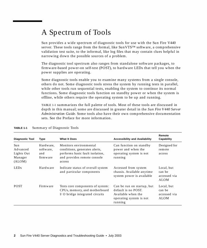
TABLE 1-1 summarizes the full palette of tools. Most of these tools are discussed in
depth in this manual; some are discussed in greater detail in the Sun Fire V440 ServerAdministration Guide. Some tools also have their own comprehensive documentation
sets. See the Preface for more information.
TABLE 1-1 Summary of Diagnostic Tools
Diagnostic Tool Type What It Does Accessibility and AvailabilityRemoteCapability
Sun
Advanced
Lights Out
Manager
(ALOM)
Hardware,
software,
and
firmware
Monitors environmental
conditions, generates alerts,
performs basic fault isolation,
and provides remote console
access
Can function on standby
power and when the
operating system is not
running
Designed for
remote
access
LEDs Hardware Indicate status of overall system
and particular components
Accessed from system
chassis. Available anytime
system power is available
Local, but
can be
accessed via
ALOM
POST Firmware Tests core components of system:
CPUs, memory, and motherboard
I/O bridge integrated circuits
Can be run on startup, but
default is no POST.
Available when the
operating system is not
running
Local, but
can be
accessed via
ALOM
2 Sun Fire V440 Server Diagnostics and Troubleshooting Guide • July 2003

Why are there so many different diagnostic tools?
There are a number of reasons for the lack of a single all-in-one diagnostic test,
starting with the complexity of the server.
Consider the bus repeater circuit built into every Sun Fire V440 server. This circuit
interconnects all CPUs and high-speed I/O interfaces (see FIGURE 1-1), sensing and
adapting its communications depending on how many CPU modules are present.
This sophisticated high-speed interconnect represents just one facet of the Sun Fire
V440 server’s advanced architecture.
OpenBoot
Diagnostics
Firmware Tests system components,
focusing on peripherals and
I/O devices
Can be run automatically at
startup, but the default is
no diagnostics. Can also be
run interactively. Available
when the operating system
is not running
Local, but
can be
accessed via
ALOM
OpenBoot
commands
Firmware Display various kinds of system
information
Available when the
operating system is not
running
Local, but
can be
accessed via
ALOM
Solaris
commands
Software Display various kinds of system
information
Requires operating system Local, and
over
network
SunVTS Software Exercises and stresses the system,
running tests in parallel
Requires operating system.
You may need to install
SunVTS software
separately
View and
control over
network
Sun
Management
Center
Software Monitors both hardware
environmental conditions and
software performance of multiple
systems. Generates alerts for
various conditions
Requires operating system
to be running on both
monitored and master
systems. Requires a
dedicated database on the
master server
Designed for
remote
access
Hardware
Diagnostic
Suite
Software Exercises an operational system
by running sequential tests. Also
reports failed field-replaceable
units (FRUs)
Separately purchased
optional add-on to Sun
Management Center.
Requires operating system
and Sun Management
Center software
Designed for
remote
access
TABLE 1-1 Summary of Diagnostic Tools (Continued)
Diagnostic Tool Type What It Does Accessibility and AvailabilityRemoteCapability
Chapter 1 Diagnostic Tools Overview 3

FIGURE 1-1 Simplified Schematic View of a Sun Fire V440 Server
Consider also that some diagnostics must function even when the system fails to
boot. Any diagnostic capable of isolating problems when the system fails to boot
must be independent of the operating system. But any diagnostic that is
independent of the operating system will also be unable to make use of the
operating system’s considerable resources for getting at the more complex causes of
failures.
Another complicating factor is that different sites have differing diagnostic
requirements. You may be administering a single computer or a whole data center
full of equipment in racks. Alternatively, your systems may be deployed remotely—
perhaps in areas that are physically inaccessible.
Memory
CPU 0
Motherboard
I/OBridge
I/OBridge
BootPROM
SCSI DiskController
PCI Slots
I2C
ALOMSCC
Memory
CPU 1
Memory
CPU 2
Memory
CPU 3
XBusPCIBus
PCIBus
JBusJBus
TTYB
PCI Slots
EthernetController
I2CController
Bus
To power supplies, fans, and other components
EthernetControllerSCSI,
USB andEthernetPorts PCI
Bus
SERIAL MGTNET MGT
PCIBus
JBus
PCIBridge
USB& DVD
Controllers
Bus Repeater Circuit
4 Sun Fire V440 Server Diagnostics and Troubleshooting Guide • July 2003
Finally, consider the different tasks you expect to perform with your diagnostic
tools:
■ Isolating faults to a specific replaceable hardware component
■ Exercising the system to disclose more subtle problems that may or may not be
hardware related
■ Monitoring the system to catch problems before they become serious enough to
cause unplanned downtime
Not every diagnostic tool can be optimized for all these varied tasks.
Instead of one unified diagnostic tool, Sun provides a palette of tools each of which
has its own specific strengths and applications. To best appreciate how each tool fits
into the larger picture, it is necessary to have some understanding of what happens
when the server starts up, during the so-called boot process. This is discussed in the
next chapter.
Chapter 1 Diagnostic Tools Overview 5

6 Sun Fire V440 Server Diagnostics and Troubleshooting Guide • July 2003

CHAPTER 2
Diagnostics and the Boot Process
This chapter introduces the tools that let you accomplish the goals of isolating faults
and monitoring and exercising systems. It also helps you to understand how the
various tools fit together.
Topics in this chapter include:
■ “About Diagnostics and the Boot Process” on page 8
■ “About Isolating Faults in the System” on page 32
■ “About Monitoring the System” on page 34
■ “About Exercising the System” on page 39
■ “Reference for Identifying Memory Modules” on page 43
■ “Reference for OpenBoot Diagnostics Test Descriptions” on page 47
■ “Reference for Decoding I2C Diagnostic Test Messages” on page 49
■ “Reference for Terms in Diagnostic Output” on page 51
If you only want instructions for using diagnostic tools, skip this chapter and turn to:
■ Chapter 3, for part isolating procedures
■ Chapter 4, for system monitoring procedures
■ Chapter 5, for system exercising procedures
You may also find it helpful to turn to:
■ Appendix A, for information about the system console
7
About Diagnostics and the Boot Process
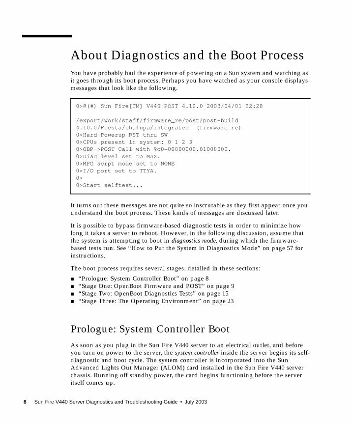
You have probably had the experience of powering on a Sun system and watching as
it goes through its boot process. Perhaps you have watched as your console displays
messages that look like the following.
It turns out these messages are not quite so inscrutable as they first appear once you
understand the boot process. These kinds of messages are discussed later.
It is possible to bypass firmware-based diagnostic tests in order to minimize how
long it takes a server to reboot. However, in the following discussion, assume that
the system is attempting to boot in diagnostics mode, during which the firmware-
based tests run. See “How to Put the System in Diagnostics Mode” on page 57 for
instructions.
The boot process requires several stages, detailed in these sections:
■ “Prologue: System Controller Boot” on page 8
■ “Stage One: OpenBoot Firmware and POST” on page 9
■ “Stage Two: OpenBoot Diagnostics Tests” on page 15
■ “Stage Three: The Operating Environment” on page 23
Prologue: System Controller Boot
As soon as you plug in the Sun Fire V440 server to an electrical outlet, and before
you turn on power to the server, the system controller inside the server begins its self-
diagnostic and boot cycle. The system controller is incorporated into the Sun
Advanced Lights Out Manager (ALOM) card installed in the Sun Fire V440 server
chassis. Running off standby power, the card begins functioning before the server
itself comes up.
0>@(#) Sun Fire[TM] V440 POST 4.10.0 2003/04/01 22:28
/export/work/staff/firmware_re/post/post-build4.10.0/Fiesta/chalupa/integrated (firmware_re)0>Hard Powerup RST thru SW0>CPUs present in system: 0 1 2 30>OBP->POST Call with %o0=00000000.01008000.0>Diag level set to MAX.0>MFG scrpt mode set to NONE0>I/O port set to TTYA.0>0>Start selftest...
8 Sun Fire V440 Server Diagnostics and Troubleshooting Guide • July 2003
The system controller provides access to a number of control and monitoring
functions through the ALOM command-line interface. For more information about
ALOM, see “Monitoring the System Using Sun Advanced Lights Out Manager” on
page 35.
Stage One: OpenBoot Firmware and POST
Every Sun Fire V440 server includes a chip holding about 2 Mbytes of firmware-
based code. This chip is called the boot PROM. After you turn on system power, the
first thing the system does is execute code that resides in the boot PROM.
This code, which is referred to as the OpenBoot™ firmware, is a small-scale operating
system unto itself. However, unlike a traditional operating system that can run
multiple applications for multiple simultaneous users, OpenBoot firmware runs in
single-user mode and is designed solely to configure and boot the system. OpenBoot
firmware also initiates firmware-based diagnostics that test the system, thereby
ensuring that the hardware is sufficiently “healthy” to run its normal operating
environment.
When system power is turned on, the OpenBoot firmware begins running directly
out of the boot PROM, since at this stage system memory has not been verified to
work properly.
Soon after power is turned on, the system hardware determines that at least one
CPU is powered on, and is submitting a bus access request, which indicates that the
CPU in question is at least partly functional. This becomes the master CPU, and is
responsible for executing OpenBoot firmware instructions.
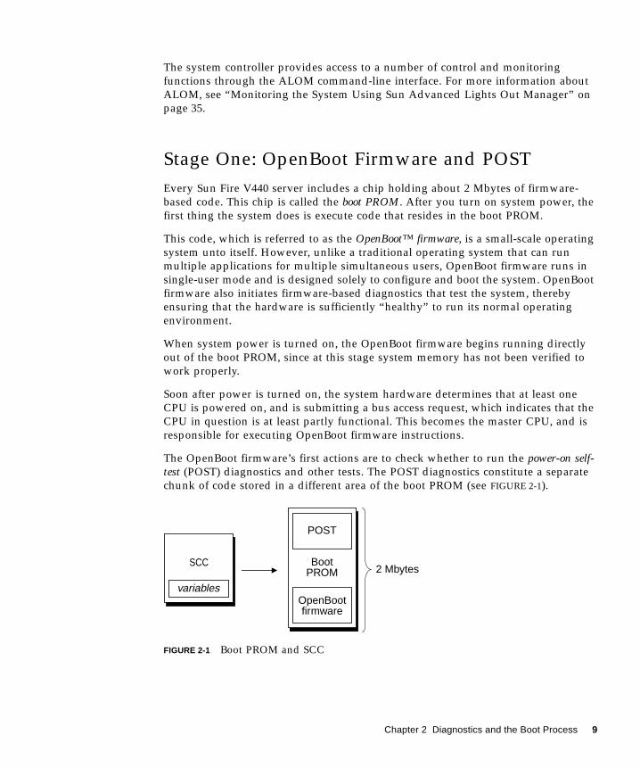
The OpenBoot firmware’s first actions are to check whether to run the power-on self-test (POST) diagnostics and other tests. The POST diagnostics constitute a separate
chunk of code stored in a different area of the boot PROM (see FIGURE 2-1).
FIGURE 2-1 Boot PROM and SCC
SCC BootPROM
POST
2 Mbytes
OpenBootfirmware
variables
Chapter 2 Diagnostics and the Boot Process 9

The extent of these power-on self-tests, and whether they are performed at all, is
controlled by configuration variables stored in the removable system configuration
card (SCC). These OpenBoot configuration variables are discussed in “Controlling
POST Diagnostics” on page 13.
As soon as POST diagnostics can verify that some subset of system memory is
functional, tests are loaded into system memory.
The Purpose of POST Diagnostics
The POST diagnostics verify the core functionality of the system. A successful
execution of the POST diagnostics does not ensure that there is nothing wrong with
the server, but it does ensure that the server can proceed to the next stage of the boot
process.
For a Sun Fire V440 server, this means:
■ At least one of the CPUs is working.
■ At least a subset (512 Mbytes) of system memory is functional.
■ Input/output bridges located on the motherboard are functioning.
■ The PCI bus is intact—that is, there are no electrical shorts.
It is possible for a system to pass all POST diagnostics and still be unable to boot the
operating system. However, you can run POST diagnostics even when a system fails
to boot, and these tests are likely to disclose the source of most hardware problems.
POST generally reports errors that are persistent in nature. To catch intermittent
problems, consider running a system exercising tool. See “About Exercising the
System” on page 39.
What POST Diagnostics Do
Each POST diagnostic is a low-level test designed to pinpoint faults in a specific
hardware component. For example, individual memory tests called address bitwalkand data bitwalk ensure that binary 0s and 1s can be written on each address and data
line. During such a test, the POST may display output similar to this example.
In this example, CPU 1 is the master CPU, as indicated by the prompt 1>, and it is
about to test the memory associated with CPU 3, as indicated by the message
“Slave 3 .”
1>Data Bitwalk on Slave 31> Test Bank 0.
10 Sun Fire V440 Server Diagnostics and Troubleshooting Guide • July 2003
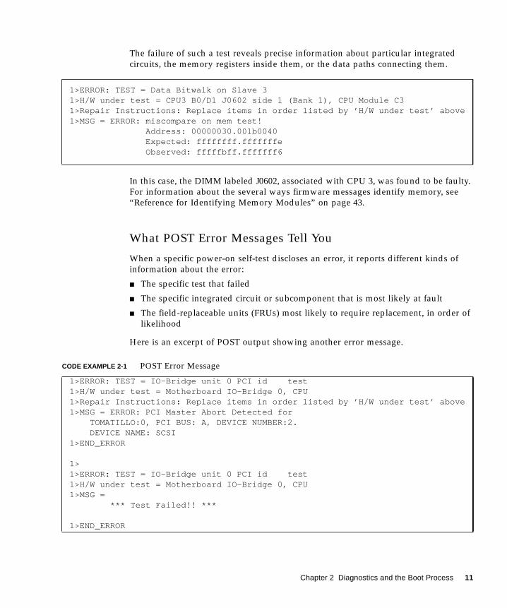
The failure of such a test reveals precise information about particular integrated
circuits, the memory registers inside them, or the data paths connecting them.
In this case, the DIMM labeled J0602, associated with CPU 3, was found to be faulty.
For information about the several ways firmware messages identify memory, see
“Reference for Identifying Memory Modules” on page 43.
What POST Error Messages Tell You
When a specific power-on self-test discloses an error, it reports different kinds of
information about the error:
■ The specific test that failed
■ The specific integrated circuit or subcomponent that is most likely at fault
■ The field-replaceable units (FRUs) most likely to require replacement, in order of
likelihood
Here is an excerpt of POST output showing another error message.
1>ERROR: TEST = Data Bitwalk on Slave 31>H/W under test = CPU3 B0/D1 J0602 side 1 (Bank 1), CPU Module C31>Repair Instructions: Replace items in order listed by ’H/W under test’ above1>MSG = ERROR: miscompare on mem test!
Address: 00000030.001b0040Expected: ffffffff.fffffffeObserved: fffffbff.fffffff6
CODE EXAMPLE 2-1 POST Error Message
1>ERROR: TEST = IO-Bridge unit 0 PCI id test1>H/W under test = Motherboard IO-Bridge 0, CPU1>Repair Instructions: Replace items in order listed by ’H/W under test’ above1>MSG = ERROR: PCI Master Abort Detected for
TOMATILLO:0, PCI BUS: A, DEVICE NUMBER:2.DEVICE NAME: SCSI
1>END_ERROR
1>1>ERROR: TEST = IO-Bridge unit 0 PCI id test1>H/W under test = Motherboard IO-Bridge 0, CPU1>MSG =
*** Test Failed!! ***
1>END_ERROR
Chapter 2 Diagnostics and the Boot Process 11
Identifying FRUs
An important feature of POST error messages is the H/W under test line. (The
second line in CODE EXAMPLE 2-1.)
The H/W under test line indicates which FRU or FRUs may be responsible for the
error. Note that in CODE EXAMPLE 2-1, two different FRUs are indicated. Using
TABLE 2-15 to decode some of the terms, you can see that this POST error was most
likely caused by bad integrated circuits (IO-Bridge ) or electrical pathways on the
motherboard. However, the error message also indicates that the master CPU, in this
case CPU 1, may be at fault. For information on how Sun Fire V440 CPUs are
numbered, see “Identifying CPU/Memory Modules” on page 46.
Though beyond the scope of this manual, it is worth noting that POST error
messages provide fault isolation capability beyond the FRU level. In the current
example, the MSGline located immediately below the H/W under test line specifies
the particular integrated circuit (DEVICE NAME: SCSI) most likely at fault. This
level of isolation is most useful at the repair depot.
Why a POST Error May Implicate Multiple FRUs
Because each test operates at such a low level, the POST diagnostics are often more
definite in reporting the minute details of the error, like the numerical values of
expected and observed results, than they are about reporting which FRU is
responsible. If this seems counter-intuitive, consider the block diagram of one data
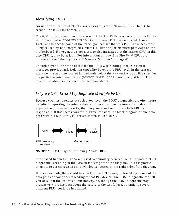
path within a Sun Fire V440 server, shown in FIGURE 2-2.
FIGURE 2-2 POST Diagnostic Running Across FRUs
The dashed line in FIGURE 2-2 represents a boundary between FRUs. Suppose a POST
diagnostic is running in the CPU in the left part of the diagram. This diagnostic
attempts to access registers in a PCI device located in the right side of the diagram.
If this access fails, there could be a fault in the PCI device, or, less likely, in one of the
data paths or components leading to that PCI device. The POST diagnostic can tell
you only that the test failed, but not why. So, though the POST diagnostic may
present very precise data about the nature of the test failure, potentially several
different FRUs could be implicated.
CPUI/O
bridgePCI
device
CPU/memory Motherboardmodule
12 Sun Fire V440 Server Diagnostics and Troubleshooting Guide • July 2003
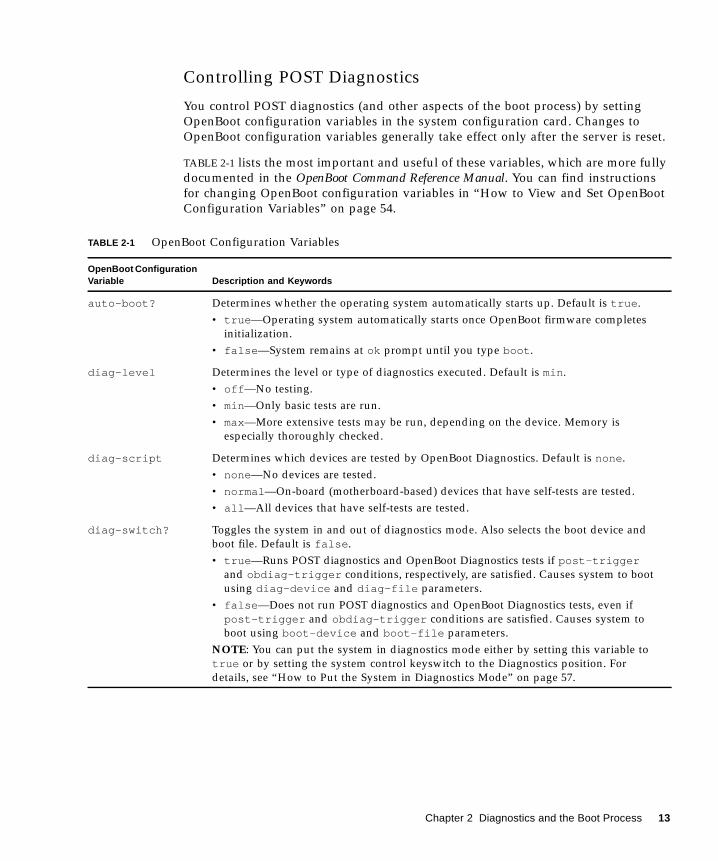
Controlling POST Diagnostics
You control POST diagnostics (and other aspects of the boot process) by setting
OpenBoot configuration variables in the system configuration card. Changes to
OpenBoot configuration variables generally take effect only after the server is reset.
TABLE 2-1 lists the most important and useful of these variables, which are more fully
documented in the OpenBoot Command Reference Manual. You can find instructions
for changing OpenBoot configuration variables in “How to View and Set OpenBoot
Configuration Variables” on page 54.
TABLE 2-1 OpenBoot Configuration Variables
OpenBoot ConfigurationVariable Description and Keywords
auto-boot? Determines whether the operating system automatically starts up. Default is true .
• true —Operating system automatically starts once OpenBoot firmware completes
initialization.
• false —System remains at ok prompt until you type boot .
diag-level Determines the level or type of diagnostics executed. Default is min .
• off —No testing.
• min —Only basic tests are run.
• max—More extensive tests may be run, depending on the device. Memory is
especially thoroughly checked.
diag-script Determines which devices are tested by OpenBoot Diagnostics. Default is none .
• none —No devices are tested.
• normal —On-board (motherboard-based) devices that have self-tests are tested.
• all —All devices that have self-tests are tested.
diag-switch? Toggles the system in and out of diagnostics mode. Also selects the boot device and
boot file. Default is false .
• true —Runs POST diagnostics and OpenBoot Diagnostics tests if post-triggerand obdiag-trigger conditions, respectively, are satisfied. Causes system to boot
using diag-device and diag-file parameters.
• false —Does not run POST diagnostics and OpenBoot Diagnostics tests, even if
post-trigger and obdiag-trigger conditions are satisfied. Causes system to
boot using boot-device and boot-file parameters.
NOTE: You can put the system in diagnostics mode either by setting this variable to
true or by setting the system control keyswitch to the Diagnostics position. For
details, see “How to Put the System in Diagnostics Mode” on page 57.
Chapter 2 Diagnostics and the Boot Process 13
Note – These variables affect OpenBoot Diagnostics tests as well as POST
diagnostics.
Diagnostics: Reliability versus Availability
The OpenBoot configuration variables described in TABLE 2-1 let you control not only
how diagnostic tests proceed, but also what triggers them.
By default, firmware-based diagnostic tests are disabled to minimize the amount of
time it takes for a server to reboot. However, skipping these tests does create some
system reliability risks.
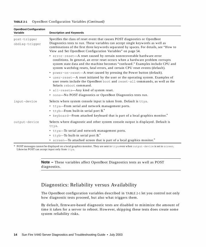
post-trigger
obdiag-trigger
Specifies the class of reset event that causes POST diagnostics or OpenBoot
Diagnostics tests to run. These variables can accept single keywords as well as
combinations of the first three keywords separated by spaces. For details, see “How to
View and Set OpenBoot Configuration Variables” on page 54.
• error-reset —A reset caused by certain nonrecoverable hardware error
conditions. In general, an error reset occurs when a hardware problem corrupts
system state data and the machine becomes “confused.” Examples include CPU and
system watchdog resets, fatal errors, and certain CPU reset events (default).
• power-on-reset —A reset caused by pressing the Power button (default).
• user-reset —A reset initiated by the user or the operating system. Examples of
user resets include the OpenBoot boot and reset-all commands, as well as the
Solaris reboot command.
• all-resets —Any kind of system reset.
• none —No POST diagnostics or OpenBoot Diagnostics tests run.
input-device Selects where system console input is taken from. Default is ttya .
• ttya —From serial and network management ports.
• ttyb —From built-in serial port B.*
• keyboard —From attached keyboard that is part of a local graphics monitor.*
output-device Selects where diagnostic and other system console output is displayed. Default is
ttya .
• ttya —To serial and network management ports.
• ttyb —To built-in serial port B.*
• screen —To attached screen that is part of a local graphics monitor.*
* POST messages cannot be displayed on a local graphics monitor. They are sent to ttya even when output-device is set to screen .Likewise POST can accept input only from ttya .
TABLE 2-1 OpenBoot Configuration Variables (Continued)
OpenBoot ConfigurationVariable Description and Keywords
14 Sun Fire V440 Server Diagnostics and Troubleshooting Guide • July 2003
Bypassing diagnostic tests can create a situation where a server with faulty hardware
gets locked into a cycle of repeated booting and crashing. Depending on the type of
problem, the cycle may repeat intermittently. Because diagnostic tests are never
invoked, the crashes may occur without leaving behind any log entries or
meaningful console messages.
The section “How to Put the System in Diagnostics Mode” on page 57 provides
instructions for ensuring that your server runs diagnostics when starting up. The
section “How to Bypass Firmware Diagnostics” on page 58 explains how to disable
firmware diagnostics.
Temporarily Bypassing Diagnostics
Even if you set up the server to run diagnostic tests automatically on reboot, it is still
possible to bypass diagnostic tests for a single boot cycle. This can be useful in cases
where you are reconfiguring the server, or on those rare occasions when POST or
OpenBoot Diagnostics tests themselves stall or “hang,” leaving the server unable to
boot and in an unusable state. These “hangs” most commonly result from firmware
corruption of some sort, especially of having flashed an incompatible firmware
image into the server’s PROMs.
If you do find yourself needing to skip diagnostic tests for a single boot cycle, the
ALOM system controller provides a convenient way to do this. See “How to Bypass
Diagnostics Temporarily” on page 59 for instructions.
Maximizing Reliability
By default, diagnostics do not run following a user- or operating system-initiated
reset. This means the system does not run diagnostics in the event of an operating
system panic. To ensure the maximum reliability, especially for automatic system
recovery (ASR), you can configure the system to run its firmware-based diagnostic
tests following all resets. For instructions, see “How to Maximize Diagnostic
Testing” on page 61.
Stage Two: OpenBoot Diagnostics Tests
Once POST diagnostics have finished running, POST marks the status of any faulty
device as “FAILED,” and returns control to OpenBoot firmware.
OpenBoot firmware compiles a hierarchical “census” of all devices in the system.
This census is called a device tree. Though different for every system configuration,
the device tree generally includes both built-in system components and optional PCI
bus devices. The device tree does not include any components marked as “FAILED”
by POST diagnostics.
Chapter 2 Diagnostics and the Boot Process 15
Following the successful execution of POST diagnostics, the OpenBoot firmware
proceeds to run OpenBoot Diagnostics tests. Like the POST diagnostics, OpenBoot
Diagnostics code is firmware-based and resides in the boot PROM.
The Purpose of OpenBoot Diagnostics Tests
OpenBoot Diagnostics tests focus on system I/O and peripheral devices. Any device
in the device tree, regardless of manufacturer, that includes an IEEE 1275-compatible
self-test is included in the suite of OpenBoot Diagnostics tests. On a Sun Fire V440
server, OpenBoot Diagnostics examine the following system components:
■ I/O interfaces; including USB and serial ports, SCSI and IDE controllers, and
Ethernet interfaces
■ ALOM card
■ Keyboard, mouse, and video (when present)
■ Inter-Integrated Circuit (I2C) bus components; including thermal and other kinds
of sensors located on the motherboard, CPU/memory modules, DIMMs, power
supply, and SCSI backplane
■ Any PCI option card with an IEEE 1275-compatible built-in self-test
The OpenBoot Diagnostics tests run automatically via a script when you start up the
system in diagnostics mode. However, you can also run OpenBoot Diagnostics tests
manually, as explained in the next section.
Like POST diagnostics, OpenBoot Diagnostics tests catch persistent errors. To
disclose intermittent problems, consider running a system exercising tool. See
“About Exercising the System” on page 39.
Controlling OpenBoot Diagnostics Tests
When you restart the system, you can run OpenBoot Diagnostics tests either
interactively from a test menu, or by entering commands directly from the okprompt.
Note – You cannot reliably run OpenBoot Diagnostics tests following an operating
system halt, since the halt leaves system memory in an unpredictable state. Best
practice is to reset the system before running these tests.
Most of the same OpenBoot configuration variables you use to control POST (see
TABLE 2-1) also affect OpenBoot Diagnostics tests. Notably, you can determine
OpenBoot Diagnostics testing level—or suppress testing entirely—by appropriately
setting the diag-level variable.
16 Sun Fire V440 Server Diagnostics and Troubleshooting Guide • July 2003
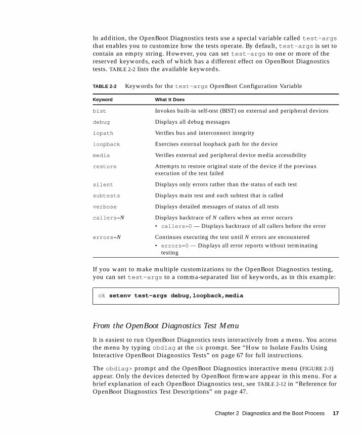
In addition, the OpenBoot Diagnostics tests use a special variable called test-argsthat enables you to customize how the tests operate. By default, test-args is set to
contain an empty string. However, you can set test-args to one or more of the
reserved keywords, each of which has a different effect on OpenBoot Diagnostics
tests. TABLE 2-2 lists the available keywords.
If you want to make multiple customizations to the OpenBoot Diagnostics testing,
you can set test-args to a comma-separated list of keywords, as in this example:
From the OpenBoot Diagnostics Test Menu
It is easiest to run OpenBoot Diagnostics tests interactively from a menu. You access
the menu by typing obdiag at the ok prompt. See “How to Isolate Faults Using
Interactive OpenBoot Diagnostics Tests” on page 67 for full instructions.
The obdiag> prompt and the OpenBoot Diagnostics interactive menu (FIGURE 2-3)
appear. Only the devices detected by OpenBoot firmware appear in this menu. For a
brief explanation of each OpenBoot Diagnostics test, see TABLE 2-12 in “Reference for
OpenBoot Diagnostics Test Descriptions” on page 47.
TABLE 2-2 Keywords for the test-args OpenBoot Configuration Variable
Keyword What It Does
bist Invokes built-in self-test (BIST) on external and peripheral devices
debug Displays all debug messages
iopath Verifies bus and interconnect integrity
loopback Exercises external loopback path for the device
media Verifies external and peripheral device media accessibility
restore Attempts to restore original state of the device if the previous
execution of the test failed
silent Displays only errors rather than the status of each test
subtests Displays main test and each subtest that is called
verbose Displays detailed messages of status of all tests
callers= N Displays backtrace of N callers when an error occurs
• callers=0 — Displays backtrace of all callers before the error
errors= N Continues executing the test until N errors are encountered
• errors=0 — Displays all error reports without terminating
testing
ok setenv test-args debug,loopback,media
Chapter 2 Diagnostics and the Boot Process 17
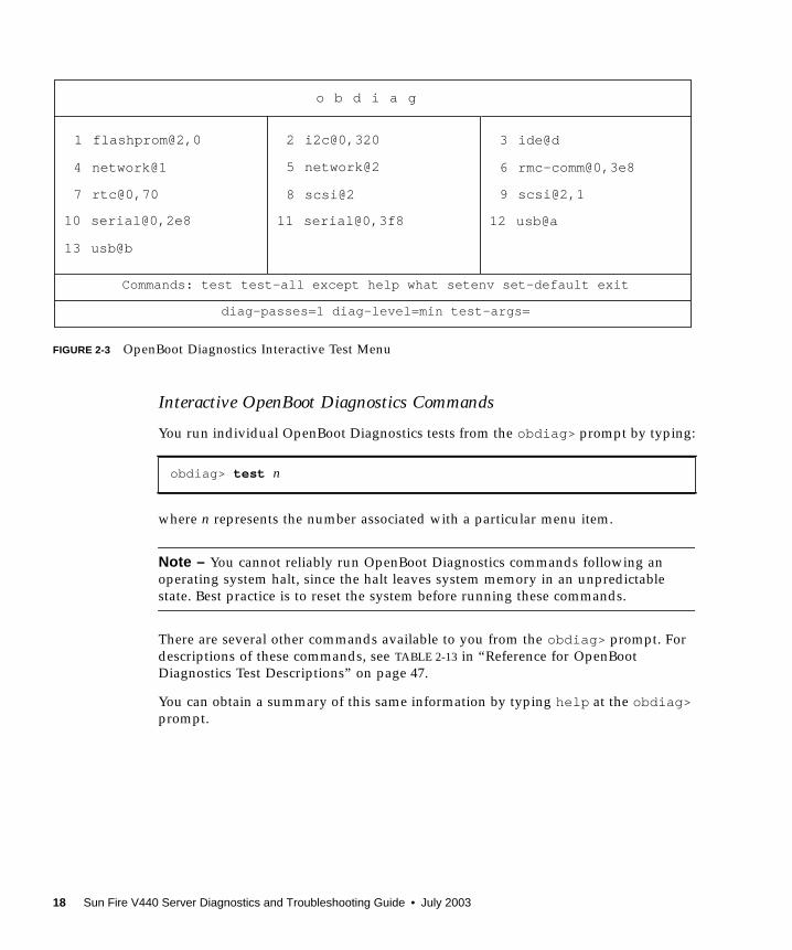
FIGURE 2-3 OpenBoot Diagnostics Interactive Test Menu
Interactive OpenBoot Diagnostics Commands
You run individual OpenBoot Diagnostics tests from the obdiag> prompt by typing:
where n represents the number associated with a particular menu item.
Note – You cannot reliably run OpenBoot Diagnostics commands following an
operating system halt, since the halt leaves system memory in an unpredictable
state. Best practice is to reset the system before running these commands.
There are several other commands available to you from the obdiag> prompt. For
descriptions of these commands, see TABLE 2-13 in “Reference for OpenBoot
Diagnostics Test Descriptions” on page 47.
You can obtain a summary of this same information by typing help at the obdiag>prompt.
obdiag> test n
o b d i a g
1 flashprom@2,0 3 ide@d
6 rmc-comm@0,3e8
9 scsi@2,1
12 usb@a
2 i2c@0,320
4 network@1
7 rtc@0,70
10 serial@0,2e8
13 usb@b
5 network@2
8 scsi@2
11 serial@0,3f8
Commands: test test-all except help what setenv set-default exit
diag-passes=1 diag-level=min test-args=
18 Sun Fire V440 Server Diagnostics and Troubleshooting Guide • July 2003
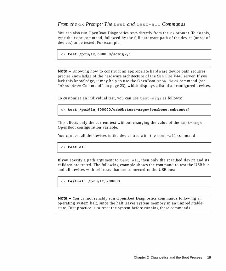
From the ok Prompt: The test and test-all Commands
You can also run OpenBoot Diagnostics tests directly from the ok prompt. To do this,
type the test command, followed by the full hardware path of the device (or set of
devices) to be tested. For example:
Note – Knowing how to construct an appropriate hardware device path requires
precise knowledge of the hardware architecture of the Sun Fire V440 server. If you
lack this knowledge, it may help to use the OpenBoot show-devs command (see
“show-devs Command” on page 23), which displays a list of all configured devices.
To customize an individual test, you can use test-args as follows:
This affects only the current test without changing the value of the test-argsOpenBoot configuration variable.
You can test all the devices in the device tree with the test-all command:
If you specify a path argument to test-all , then only the specified device and its
children are tested. The following example shows the command to test the USB bus
and all devices with self-tests that are connected to the USB bus:
Note – You cannot reliably run OpenBoot Diagnostics commands following an
operating system halt, since the halt leaves system memory in an unpredictable
state. Best practice is to reset the system before running these commands.
ok test /pci@1c,600000/scsi@2,1
ok test /pci@1e,600000/usb@b:test-args={verbose,subtests}
ok test-all
ok test-all /pci@1f,700000
Chapter 2 Diagnostics and the Boot Process 19
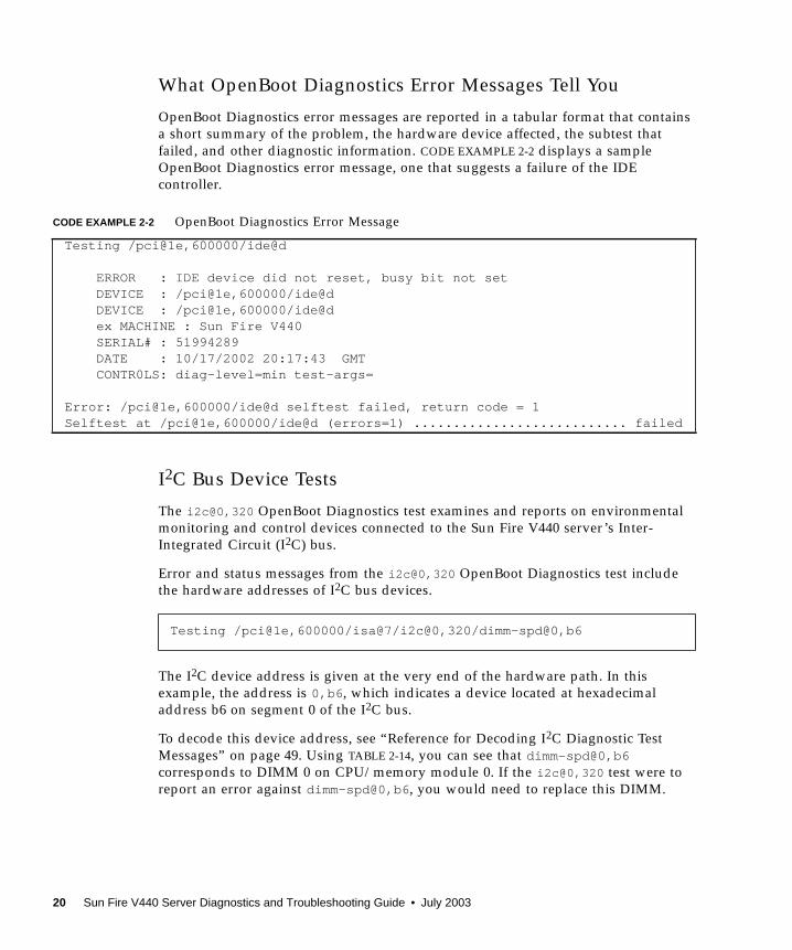
What OpenBoot Diagnostics Error Messages Tell You
OpenBoot Diagnostics error messages are reported in a tabular format that contains
a short summary of the problem, the hardware device affected, the subtest that
failed, and other diagnostic information. CODE EXAMPLE 2-2 displays a sample
OpenBoot Diagnostics error message, one that suggests a failure of the IDE
controller.
I2C Bus Device Tests
The i2c@0,320 OpenBoot Diagnostics test examines and reports on environmental
monitoring and control devices connected to the Sun Fire V440 server’s Inter-
Integrated Circuit (I2C) bus.
Error and status messages from the i2c@0,320 OpenBoot Diagnostics test include
the hardware addresses of I2C bus devices.
The I2C device address is given at the very end of the hardware path. In this
example, the address is 0,b6 , which indicates a device located at hexadecimal
address b6 on segment 0 of the I2C bus.
To decode this device address, see “Reference for Decoding I2C Diagnostic Test
Messages” on page 49. Using TABLE 2-14, you can see that dimm-spd@0,b6corresponds to DIMM 0 on CPU/memory module 0. If the i2c@0,320 test were to
report an error against dimm-spd@0,b6 , you would need to replace this DIMM.
CODE EXAMPLE 2-2 OpenBoot Diagnostics Error Message
Testing /pci@1e,600000/ide@d
ERROR : IDE device did not reset, busy bit not setDEVICE : /pci@1e,600000/ide@dDEVICE : /pci@1e,600000/ide@dex MACHINE : Sun Fire V440SERIAL# : 51994289DATE : 10/17/2002 20:17:43 GMTCONTR0LS: diag-level=min test-args=
Error: /pci@1e,600000/ide@d selftest failed, return code = 1Selftest at /pci@1e,600000/ide@d (errors=1) ........................... failed
Testing /pci@1e,600000/isa@7/i2c@0,320/dimm-spd@0,b6
20 Sun Fire V440 Server Diagnostics and Troubleshooting Guide • July 2003
Other OpenBoot Commands
Beyond the formal firmware-based diagnostic tools, there are a few commands you
can invoke from the ok prompt. These OpenBoot commands display information
that can help you assess the condition of a Sun Fire V440 server. These include the
following:
■ printenv command
■ probe-scsi and probe-scsi-all commands
■ probe-ide command
■ show-devs command
The following sections describe the information these commands give you. For
instructions on using these commands, turn to “How to Use OpenBoot Information
Commands” on page 94, or look up the appropriate man page.
printenv Command
The printenv command displays the OpenBoot configuration variables. The
display includes the current values for these variables as well as the default values.
For details, see “How to View and Set OpenBoot Configuration Variables” on
page 54.
For a list of some important OpenBoot configuration variables, see TABLE 2-1.
probe-scsi and probe-scsi-all Commands
The probe-scsi and probe-scsi-all commands diagnose problems with
attached and internal SCSI devices.
Caution – If you used the halt command or the L1-A (Stop-A) key sequence to
reach the ok prompt, then issuing the probe-scsi or probe-scsi-all command
can hang the system.
The probe-scsi command communicates with all SCSI devices connected to on-
board SCSI controllers. The probe-scsi-all command additionally accesses
devices connected to any host adapters installed in PCI slots.
For any SCSI device that is connected and active, the probe-scsi and probe-scsi-all commands display its target and unit numbers, and a device description
that includes type and manufacturer.
Chapter 2 Diagnostics and the Boot Process 21
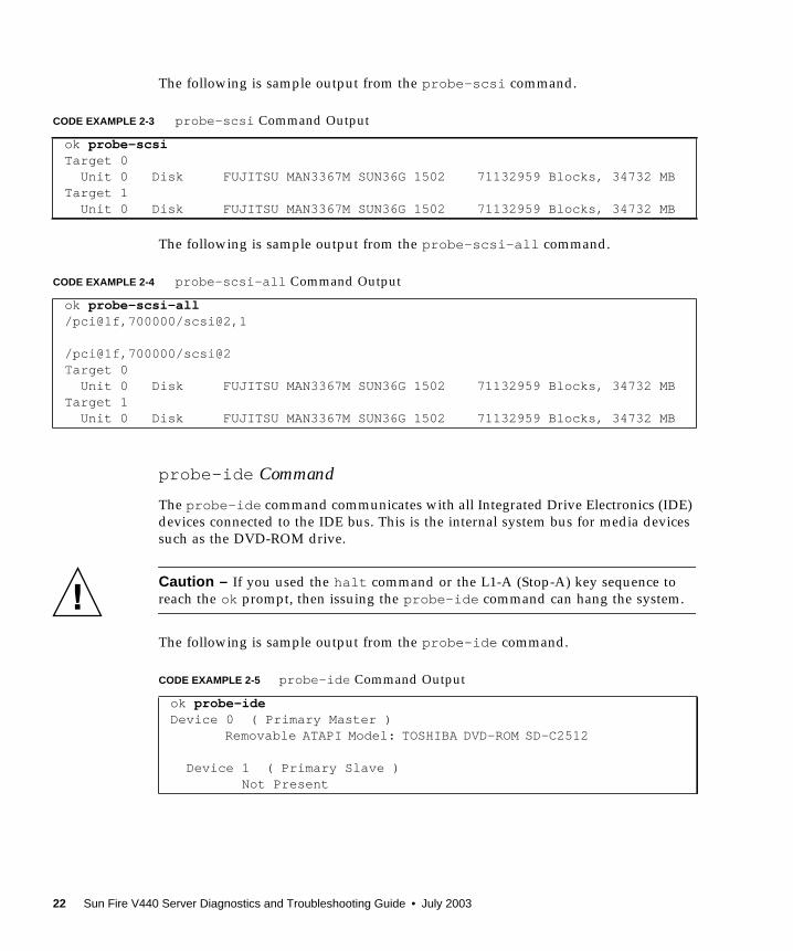
The following is sample output from the probe-scsi command.
The following is sample output from the probe-scsi-all command.
probe-ide Command
The probe-ide command communicates with all Integrated Drive Electronics (IDE)
devices connected to the IDE bus. This is the internal system bus for media devices
such as the DVD-ROM drive.
Caution – If you used the halt command or the L1-A (Stop-A) key sequence to
reach the ok prompt, then issuing the probe-ide command can hang the system.
The following is sample output from the probe-ide command.
CODE EXAMPLE 2-3 probe-scsi Command Output
ok probe-scsiTarget 0 Unit 0 Disk FUJITSU MAN3367M SUN36G 1502 71132959 Blocks, 34732 MBTarget 1 Unit 0 Disk FUJITSU MAN3367M SUN36G 1502 71132959 Blocks, 34732 MB
CODE EXAMPLE 2-4 probe-scsi-all Command Output
ok probe-scsi-all/pci@1f,700000/scsi@2,1
/pci@1f,700000/scsi@2Target 0 Unit 0 Disk FUJITSU MAN3367M SUN36G 1502 71132959 Blocks, 34732 MBTarget 1 Unit 0 Disk FUJITSU MAN3367M SUN36G 1502 71132959 Blocks, 34732 MB
CODE EXAMPLE 2-5 probe-ide Command Output
ok probe-ideDevice 0 ( Primary Master )
Removable ATAPI Model: TOSHIBA DVD-ROM SD-C2512
Device 1 ( Primary Slave ) Not Present
22 Sun Fire V440 Server Diagnostics and Troubleshooting Guide • July 2003
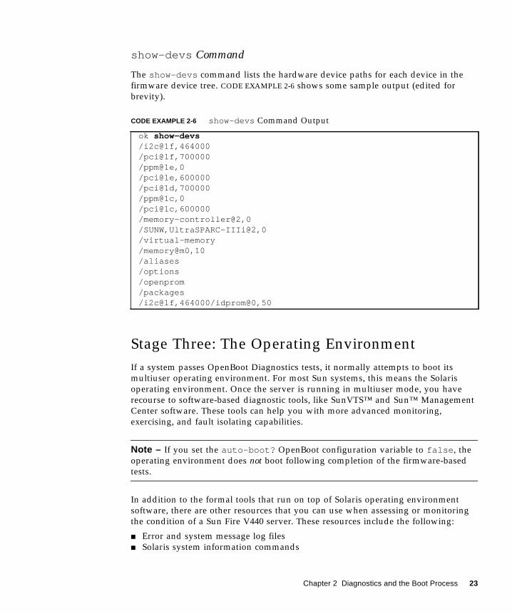
show-devs Command
The show-devs command lists the hardware device paths for each device in the
firmware device tree. CODE EXAMPLE 2-6 shows some sample output (edited for
brevity).
Stage Three: The Operating Environment
If a system passes OpenBoot Diagnostics tests, it normally attempts to boot its
multiuser operating environment. For most Sun systems, this means the Solaris
operating environment. Once the server is running in multiuser mode, you have
recourse to software-based diagnostic tools, like SunVTS™ and Sun™ Management
Center software. These tools can help you with more advanced monitoring,
exercising, and fault isolating capabilities.
Note – If you set the auto-boot? OpenBoot configuration variable to false , the
operating environment does not boot following completion of the firmware-based
tests.
In addition to the formal tools that run on top of Solaris operating environment
software, there are other resources that you can use when assessing or monitoring
the condition of a Sun Fire V440 server. These resources include the following:
■ Error and system message log files
■ Solaris system information commands
CODE EXAMPLE 2-6 show-devs Command Output
ok show-devs/i2c@1f,464000/pci@1f,700000/ppm@1e,0/pci@1e,600000/pci@1d,700000/ppm@1c,0/pci@1c,600000/memory-controller@2,0/SUNW,UltraSPARC-IIIi@2,0/virtual-memory/memory@m0,10/aliases/options/openprom/packages/i2c@1f,464000/idprom@0,50
Chapter 2 Diagnostics and the Boot Process 23
Error and System Message Log Files
Error and other system messages are saved in the file /var/adm/messages .
Messages are logged to this file from many sources, including the operating system,
the environmental control subsystem, and various software applications.
In the case of Solaris operating environment software, the syslogd daemon and its
configuration file (/etc/syslogd.conf ) control how error messages are handled.
For information about /var/adm/messages and other sources of system
information, refer to “How to Customize System Message Logging” in the SystemAdministration Guide: Advanced Administration, which is part of the Solaris System
Administration Collection.
Solaris System Information Commands
Some Solaris commands display data that you can use when assessing the condition
of a Sun Fire V440 server. These commands include the following:
■ prtconf command
■ prtdiag command
■ prtfru command
■ psrinfo command
■ showrev command
The following sections describe the information these commands give you. For
instructions on using these commands, turn to “How to Use Solaris System
Information Commands” on page 93, or look up the appropriate man page.
prtconf Command
The prtconf command displays the Solaris device tree. This tree includes all the
devices probed by OpenBoot firmware, as well as additional devices, like individual
disks, that only the operating environment software “knows” about. The output of
prtconf also includes the total amount of system memory. CODE EXAMPLE 2-7 shows
an excerpt of prtconf output (edited for brevity).
24 Sun Fire V440 Server Diagnostics and Troubleshooting Guide • July 2003
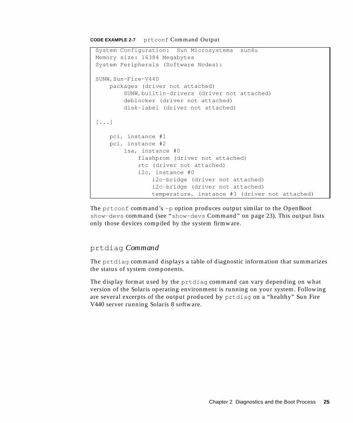
The prtconf command’s -p option produces output similar to the OpenBoot
show-devs command (see “show-devs Command” on page 23). This output lists
only those devices compiled by the system firmware.
prtdiag Command
The prtdiag command displays a table of diagnostic information that summarizes
the status of system components.
The display format used by the prtdiag command can vary depending on what
version of the Solaris operating environment is running on your system. Following
are several excerpts of the output produced by prtdiag on a “healthy” Sun Fire
V440 server running Solaris 8 software.
CODE EXAMPLE 2-7 prtconf Command Output
System Configuration: Sun Microsystems sun4uMemory size: 16384 MegabytesSystem Peripherals (Software Nodes):
SUNW,Sun-Fire-V440 packages (driver not attached) SUNW,builtin-drivers (driver not attached) deblocker (driver not attached) disk-label (driver not attached)
[...]
pci, instance #1 pci, instance #2 isa, instance #0 flashprom (driver not attached) rtc (driver not attached) i2c, instance #0 i2c-bridge (driver not attached) i2c-bridge (driver not attached) temperature, instance #3 (driver not attached)
Chapter 2 Diagnostics and the Boot Process 25
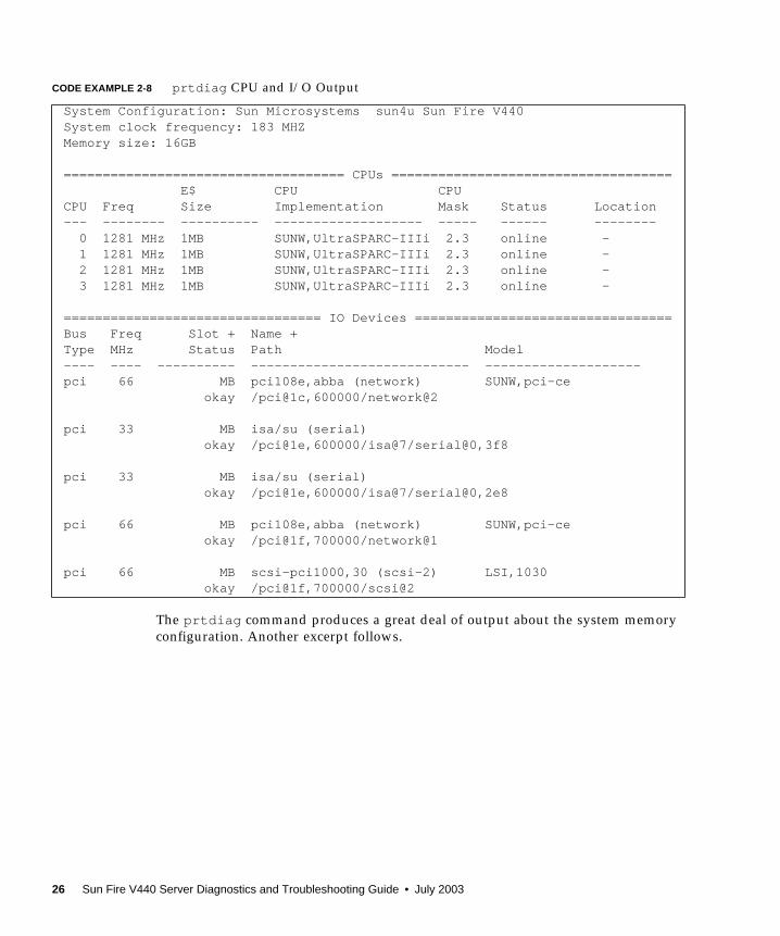
The prtdiag command produces a great deal of output about the system memory
configuration. Another excerpt follows.
CODE EXAMPLE 2-8 prtdiag CPU and I/O Output
System Configuration: Sun Microsystems sun4u Sun Fire V440System clock frequency: 183 MHZMemory size: 16GB
==================================== CPUs ==================================== E$ CPU CPUCPU Freq Size Implementation Mask Status Location--- -------- ---------- ------------------- ----- ------ -------- 0 1281 MHz 1MB SUNW,UltraSPARC-IIIi 2.3 online - 1 1281 MHz 1MB SUNW,UltraSPARC-IIIi 2.3 online - 2 1281 MHz 1MB SUNW,UltraSPARC-IIIi 2.3 online - 3 1281 MHz 1MB SUNW,UltraSPARC-IIIi 2.3 online -
================================= IO Devices =================================Bus Freq Slot + Name +Type MHz Status Path Model---- ---- ---------- ---------------------------- --------------------pci 66 MB pci108e,abba (network) SUNW,pci-ce okay /pci@1c,600000/network@2
pci 33 MB isa/su (serial) okay /pci@1e,600000/isa@7/serial@0,3f8
pci 33 MB isa/su (serial) okay /pci@1e,600000/isa@7/serial@0,2e8
pci 66 MB pci108e,abba (network) SUNW,pci-ce okay /pci@1f,700000/network@1
pci 66 MB scsi-pci1000,30 (scsi-2) LSI,1030 okay /pci@1f,700000/scsi@2
26 Sun Fire V440 Server Diagnostics and Troubleshooting Guide • July 2003

In addition to the preceding information, prtdiag with the verbose option (-v ) also
reports on front panel status, disk status, fan status, power supplies, hardware
revisions, and system temperatures.
CODE EXAMPLE 2-9 prtdiag Memory Configuration Output
============================ Memory Configuration ============================Segment Table:-----------------------------------------------------------------------Base Address Size Interleave Factor Contains-----------------------------------------------------------------------0x0 4GB 16 BankIDs 0,1,2,3, ... ,150x1000000000 4GB 16 BankIDs 16,17,18, ... ,310x2000000000 4GB 16 BankIDs 32,33,34, ... ,470x3000000000 4GB 2 BankIDs 48,49
Bank Table:----------------------------------------------------------- Physical LocationID ControllerID GroupID Size Interleave Way-----------------------------------------------------------0 0 0 256MB 0,1,2,3, ... ,151 0 0 256MB
[...]
48 3 0 2GB 0,149 3 0 2GB
Memory Module Groups:--------------------------------------------------ControllerID GroupID Labels Status--------------------------------------------------0 0 C0/P0/B0/D00 0 C0/P0/B0/D1
[...]
3 0 C3/P0/B0/D1
CODE EXAMPLE 2-10 prtdiag Verbose Output
Temperature sensors:
---------------------------------------------------------------
Location Sensor Temperature Lo LoWarn HiWarn Hi Status
---------------------------------------------------------------
SCSIBP T_AMB 26C -11C 0C 65C 75C okay
C0/P0 T_CORE 55C -10C 0C 97C 102C okay
Chapter 2 Diagnostics and the Boot Process 27
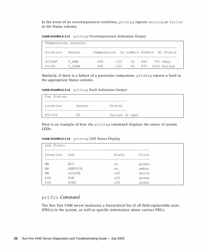
In the event of an overtemperature condition, prtdiag reports warning or failedin the Status column.
Similarly, if there is a failure of a particular component, prtdiag reports a fault in
the appropriate Status column.
Here is an example of how the prtdiag command displays the status of system
LEDs.
prtfru Command
The Sun Fire V440 server maintains a hierarchical list of all field-replaceable units
(FRUs) in the system, as well as specific information about various FRUs.
CODE EXAMPLE 2-11 prtdiag Overtemperature Indication Output
Temperature sensors:
---------------------------------------------------------------
Location Sensor Temperature Lo LoWarn HiWarn Hi Status
---------------------------------------------------------------
SCSIBP T_AMB 26C -11C 0C 65C 75C okay
C0/P0 T_CORE 99C -10C 0C 97C 102C failed
CODE EXAMPLE 2-12 prtdiag Fault Indication Output
Fan Status:
---------------------------------------
Location Sensor Status
---------------------------------------
FT1/F0 F0 failed (0 rpm)
CODE EXAMPLE 2-13 prtdiag LED Status Display
Led State:
--------------------------------------------------
Location Led State Color
--------------------------------------------------
MB ACT on green
MB SERVICE on amber
MB LOCATE off white
PS0 POK off green
PS0 STBY off green
28 Sun Fire V440 Server Diagnostics and Troubleshooting Guide • July 2003
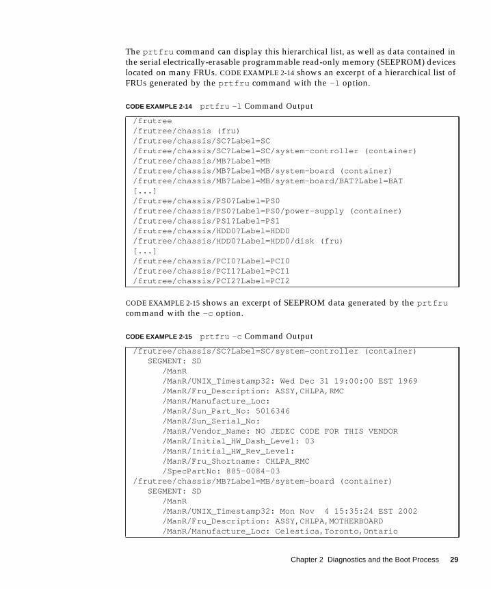
The prtfru command can display this hierarchical list, as well as data contained in
the serial electrically-erasable programmable read-only memory (SEEPROM) devices
located on many FRUs. CODE EXAMPLE 2-14 shows an excerpt of a hierarchical list of
FRUs generated by the prtfru command with the -l option.
CODE EXAMPLE 2-15 shows an excerpt of SEEPROM data generated by the prtfrucommand with the -c option.
CODE EXAMPLE 2-14 prtfru -l Command Output
/frutree/frutree/chassis (fru)/frutree/chassis/SC?Label=SC/frutree/chassis/SC?Label=SC/system-controller (container)/frutree/chassis/MB?Label=MB/frutree/chassis/MB?Label=MB/system-board (container)/frutree/chassis/MB?Label=MB/system-board/BAT?Label=BAT[...]/frutree/chassis/PS0?Label=PS0/frutree/chassis/PS0?Label=PS0/power-supply (container)/frutree/chassis/PS1?Label=PS1/frutree/chassis/HDD0?Label=HDD0/frutree/chassis/HDD0?Label=HDD0/disk (fru)[...]/frutree/chassis/PCI0?Label=PCI0/frutree/chassis/PCI1?Label=PCI1/frutree/chassis/PCI2?Label=PCI2
CODE EXAMPLE 2-15 prtfru -c Command Output
/frutree/chassis/SC?Label=SC/system-controller (container) SEGMENT: SD /ManR /ManR/UNIX_Timestamp32: Wed Dec 31 19:00:00 EST 1969 /ManR/Fru_Description: ASSY,CHLPA,RMC /ManR/Manufacture_Loc: /ManR/Sun_Part_No: 5016346 /ManR/Sun_Serial_No: /ManR/Vendor_Name: NO JEDEC CODE FOR THIS VENDOR /ManR/Initial_HW_Dash_Level: 03 /ManR/Initial_HW_Rev_Level: /ManR/Fru_Shortname: CHLPA_RMC /SpecPartNo: 885-0084-03/frutree/chassis/MB?Label=MB/system-board (container) SEGMENT: SD /ManR /ManR/UNIX_Timestamp32: Mon Nov 4 15:35:24 EST 2002 /ManR/Fru_Description: ASSY,CHLPA,MOTHERBOARD /ManR/Manufacture_Loc: Celestica,Toronto,Ontario
Chapter 2 Diagnostics and the Boot Process 29
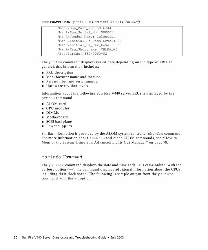
The prtfru command displays varied data depending on the type of FRU. In
general, this information includes:
■ FRU description
■ Manufacturer name and location
■ Part number and serial number
■ Hardware revision levels
Information about the following Sun Fire V440 server FRUs is displayed by the
prtfru command:
■ ALOM card
■ CPU modules
■ DIMMs
■ Motherboard
■ SCSI backplane
■ Power supplies
Similar information is provided by the ALOM system controller showfru command.
For more information about showfru and other ALOM commands, see “How to
Monitor the System Using Sun Advanced Lights Out Manager” on page 79.
psrinfo Command
The psrinfo command displays the date and time each CPU came online. With the
verbose option (-v ), the command displays additional information about the CPUs,
including their clock speed. The following is sample output from the psrinfocommand with the -v option.
/ManR/Sun_Part_No: 5016344 /ManR/Sun_Serial_No: 000001 /ManR/Vendor_Name: Celestica /ManR/Initial_HW_Dash_Level: 03 /ManR/Initial_HW_Rev_Level: 06 /ManR/Fru_Shortname: CHLPA_MB /SpecPartNo: 885-0060-02
CODE EXAMPLE 2-15 prtfru -c Command Output (Continued)
30 Sun Fire V440 Server Diagnostics and Troubleshooting Guide • July 2003
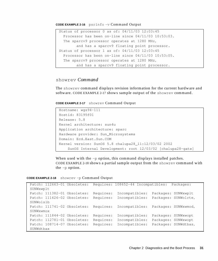
showrev Command
The showrev command displays revision information for the current hardware and
software. CODE EXAMPLE 2-17 shows sample output of the showrev command.
When used with the -p option, this command displays installed patches.
CODE EXAMPLE 2-18 shows a partial sample output from the showrev command with
the -p option.
CODE EXAMPLE 2-16 psrinfo -v Command Output
Status of processor 0 as of: 04/11/03 12:03:45
Processor has been on-line since 04/11/03 10:53:03.
The sparcv9 processor operates at 1280 MHz,
and has a sparcv9 floating point processor.
Status of processor 1 as of: 04/11/03 12:03:45
Processor has been on-line since 04/11/03 10:53:05.
The sparcv9 processor operates at 1280 MHz,
and has a sparcv9 floating point processor.
CODE EXAMPLE 2-17 showrev Command Output
Hostname: wgs94-111
Hostid: 83195f01
Release: 5.8
Kernel architecture: sun4u
Application architecture: sparc
Hardware provider: Sun_Microsystems
Domain: Ecd.East.Sun.COM
Kernel version: SunOS 5.8 chalupa28_11:12/03/02 2002
SunOS Internal Development: root 12/03/02 [chalupa28-gate]
CODE EXAMPLE 2-18 showrev -p Command Output
Patch: 112663-01 Obsoletes: Requires: 108652-44 Incompatibles: Packages:SUNWxwpltPatch: 111382-01 Obsoletes: Requires: Incompatibles: Packages: SUNWxwpltPatch: 111626-02 Obsoletes: Requires: Incompatibles: Packages: SUNWolrte,SUNWolslbPatch: 111741-02 Obsoletes: Requires: Incompatibles: Packages: SUNWxwmod,SUNWxwmoxPatch: 111844-02 Obsoletes: Requires: Incompatibles: Packages: SUNWxwoptPatch: 112781-01 Obsoletes: Requires: Incompatibles: Packages: SUNWxwoptPatch: 108714-07 Obsoletes: Requires: Incompatibles: Packages: SUNWdtbas,SUNWdtbax
Chapter 2 Diagnostics and the Boot Process 31
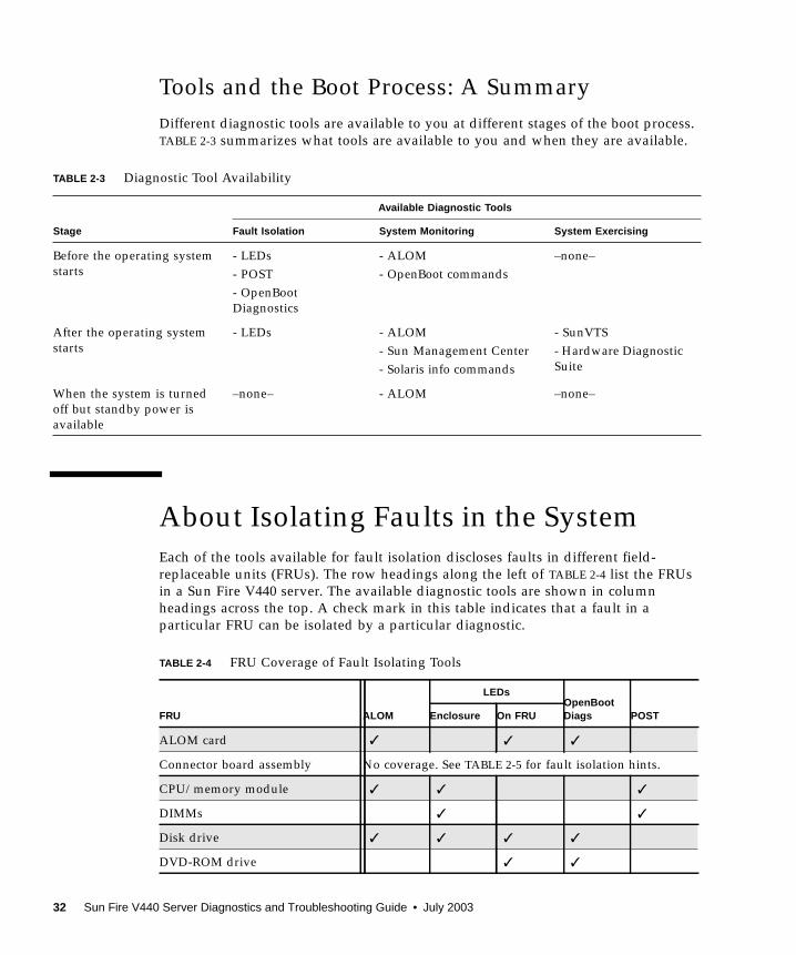
Tools and the Boot Process: A Summary
Different diagnostic tools are available to you at different stages of the boot process.
TABLE 2-3 summarizes what tools are available to you and when they are available.
About Isolating Faults in the System
Each of the tools available for fault isolation discloses faults in different field-
replaceable units (FRUs). The row headings along the left of TABLE 2-4 list the FRUs
in a Sun Fire V440 server. The available diagnostic tools are shown in column
headings across the top. A check mark in this table indicates that a fault in a
particular FRU can be isolated by a particular diagnostic.
TABLE 2-3 Diagnostic Tool Availability
Stage
Available Diagnostic Tools
Fault Isolation System Monitoring System Exercising
Before the operating system
starts
- LEDs
- POST
- OpenBoot
Diagnostics
- ALOM
- OpenBoot commands
–none–
After the operating system
starts
- LEDs - ALOM
- Sun Management Center
- Solaris info commands
- SunVTS
- Hardware Diagnostic
Suite
When the system is turned
off but standby power is
available
–none– - ALOM –none–
TABLE 2-4 FRU Coverage of Fault Isolating Tools
FRU ALOM
LEDsOpenBootDiags POSTEnclosure On FRU
ALOM card ✓ ✓ ✓
Connector board assembly No coverage. See TABLE 2-5 for fault isolation hints.
CPU/memory module ✓ ✓ ✓
DIMMs ✓ ✓
Disk drive ✓ ✓ ✓ ✓
DVD-ROM drive ✓ ✓
32 Sun Fire V440 Server Diagnostics and Troubleshooting Guide • July 2003

In addition to the FRUs listed in TABLE 2-4, there are several minor replaceable
system components—mostly cables—that cannot directly be isolated by any system
diagnostic. For the most part, you determine when these components are faulty by
eliminating other possibilities. Some of these FRUs are listed in TABLE 2-5, along with
hints on how to discern problems with them.
Fan tray 0 (PCI fan) ✓ ✓
Fan tray 1 (CPU fans) ✓ ✓
Motherboard ✓ ✓ ✓ ✓
Power supply ✓ ✓ ✓
SCSI backplane No coverage. See TABLE 2-5 for fault isolation hints.
System configuration card reader No coverage. See TABLE 2-5 for fault isolation hints.
System configuration card No coverage. See TABLE 2-5 for fault isolation hints.
TABLE 2-5 FRUs Not Directly Isolated by Fault Isolating Tools
FRU Diagnostic Hints
Connector board assembly This is difficult to distinguish from problems with similar
symptoms. The firmware generates many error messages
about being unable to access OpenBoot configuration
variables, for example: “Could not read diag-levelfrom NVRAM!” ALOM shows the front panel Service
Required indicator is lit.
Connector board power
cable
If ALOM is able to read the system keyswitch position, but
reports that none of the fans are spinning, you should
suspect that this cable is loose or defective.
DVD-ROM drive cable If OpenBoot Diagnostics tests indicate a problem with the
CD/DVD drive, but replacing the drive does not fix the
problem, you should suspect (primarily) that this cable is
either defective or improperly connected, or (secondarily)
that there is a problem with the motherboard.
SCSI backplane Though not an exhaustive diagnostic, some SunVTS tests
(i2c2test and disktest ) exercise certain SCSI backplane
paths. You can also monitor the backplane’s ambient
temperature using the ALOM system controller
showenvironment command (see “How to Monitor the
System Using Sun Advanced Lights Out Manager” on
page 79).
TABLE 2-4 FRU Coverage of Fault Isolating Tools (Continued)
FRU ALOM
LEDsOpenBootDiags POSTEnclosure On FRU
Chapter 2 Diagnostics and the Boot Process 33
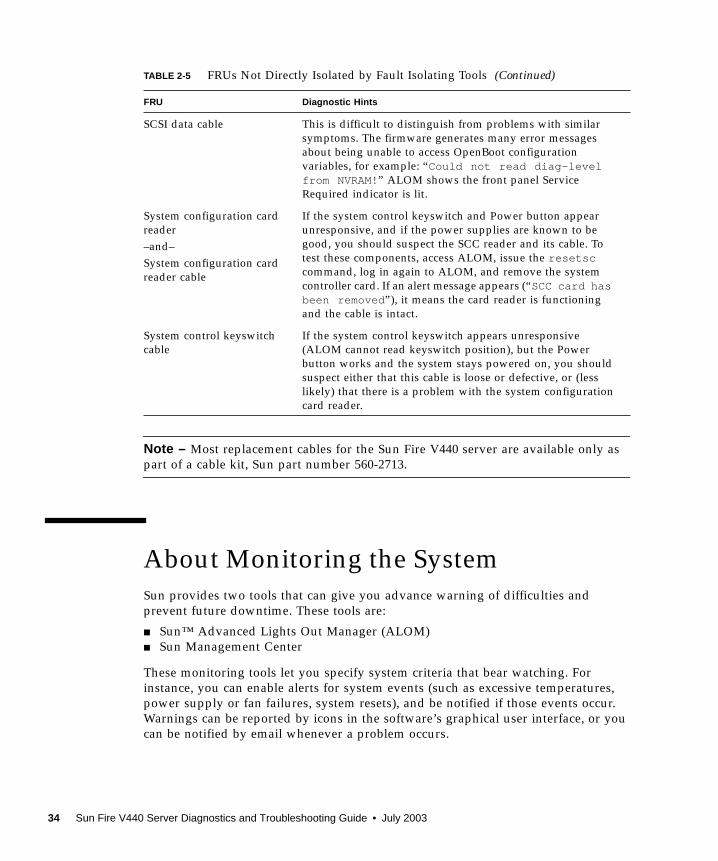
Note – Most replacement cables for the Sun Fire V440 server are available only as
part of a cable kit, Sun part number 560-2713.
About Monitoring the System
Sun provides two tools that can give you advance warning of difficulties and
prevent future downtime. These tools are:
■ Sun™ Advanced Lights Out Manager (ALOM)
■ Sun Management Center
These monitoring tools let you specify system criteria that bear watching. For
instance, you can enable alerts for system events (such as excessive temperatures,
power supply or fan failures, system resets), and be notified if those events occur.
Warnings can be reported by icons in the software’s graphical user interface, or you
can be notified by email whenever a problem occurs.
SCSI data cable This is difficult to distinguish from problems with similar
symptoms. The firmware generates many error messages
about being unable to access OpenBoot configuration
variables, for example: “Could not read diag-levelfrom NVRAM!” ALOM shows the front panel Service
Required indicator is lit.
System configuration card
reader
–and–
System configuration card
reader cable
If the system control keyswitch and Power button appear
unresponsive, and if the power supplies are known to be
good, you should suspect the SCC reader and its cable. To
test these components, access ALOM, issue the resetsccommand, log in again to ALOM, and remove the system
controller card. If an alert message appears (“SCC card hasbeen removed ”), it means the card reader is functioning
and the cable is intact.
System control keyswitch
cable
If the system control keyswitch appears unresponsive
(ALOM cannot read keyswitch position), but the Power
button works and the system stays powered on, you should
suspect either that this cable is loose or defective, or (less
likely) that there is a problem with the system configuration
card reader.
TABLE 2-5 FRUs Not Directly Isolated by Fault Isolating Tools (Continued)
FRU Diagnostic Hints
34 Sun Fire V440 Server Diagnostics and Troubleshooting Guide • July 2003
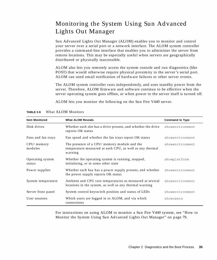
Monitoring the System Using Sun Advanced
Lights Out Manager
Sun Advanced Lights Out Manager (ALOM) enables you to monitor and control
your server over a serial port or a network interface. The ALOM system controller
provides a command-line interface that enables you to administer the server from
remote locations. This may be especially useful when servers are geographically
distributed or physically inaccessible.
ALOM also lets you remotely access the system console and run diagnostics (like
POST) that would otherwise require physical proximity to the server’s serial port.
ALOM can send email notification of hardware failures or other server events.
The ALOM system controller runs independently, and uses standby power from the
server. Therefore, ALOM firmware and software continue to be effective when the
server operating system goes offline, or when power to the server itself is turned off.
ALOM lets you monitor the following on the Sun Fire V440 server.
For instructions on using ALOM to monitor a Sun Fire V440 system, see “How to
Monitor the System Using Sun Advanced Lights Out Manager” on page 79.
TABLE 2-6 What ALOM Monitors
Item Monitored What ALOM Reveals Command to Type
Disk drives Whether each slot has a drive present, and whether the drive
reports OK status
showenvironment
Fans and fan trays Fan speed and whether the fan trays report OK status showenvironment
CPU/memory
modules
The presence of a CPU/memory module and the
temperature measured at each CPU, as well as any thermal
warning
showenvironment
Operating system
status
Whether the operating system is running, stopped,
initializing, or in some other state
showplatform
Power supplies Whether each bay has a power supply present, and whether
the power supply reports OK status
showenvironment
System temperature Ambient and CPU core temperatures as measured at several
locations in the system, as well as any thermal warning
showenvironment
Server front panel System control keyswitch position and status of LEDs showenvironment
User sessions Which users are logged in to ALOM, and via which
connections
showusers
Chapter 2 Diagnostics and the Boot Process 35

Monitoring the System Using Sun Management
Center
Sun Management Center software provides enterprise-wide monitoring of Sun
servers and workstations, including their subsystems, components, and peripheral
devices. The system being monitored must be up and running, and you need to
install all the proper software components on various systems in your network.
Individual devices are divided into three categories: physical, logical, and
environmental. Sun Management Center lets you monitor the following devices on
the Sun Fire V440 server.
How Sun Management Center Reports Status
For each device in a monitored Sun Fire V440 server, Sun Management Center
distinguishes between and reports the statuses given in TABLE 2-8.
TABLE 2-7 What Sun Management Center Monitors
Device Monitored Device Category What Sun Management Center Reveals
CPUs Logical CPU presence and status
Environmental CPU temperature and thermal warnings
DIMMs Physical Module presence and error information
Disk drives Logical Drive presence, status, and error information
Indicators (LEDs) Logical Indicator status
Fans Physical Fan presence and status
Environmental Fan speed
Network
interfaces
Logical Device presence, status, and error information
PCI cards Physical Card presence
Power supplies Physical Power supply presence and status
Environmental System voltages and currents
TABLE 2-8 Device Status Reported by Sun Management Center
Status Meaning
Degraded Device is operating at less than peak performance
Error Problem detected
Failure Predicted Available statistics suggest that device failure is imminent
36 Sun Fire V440 Server Diagnostics and Troubleshooting Guide • July 2003
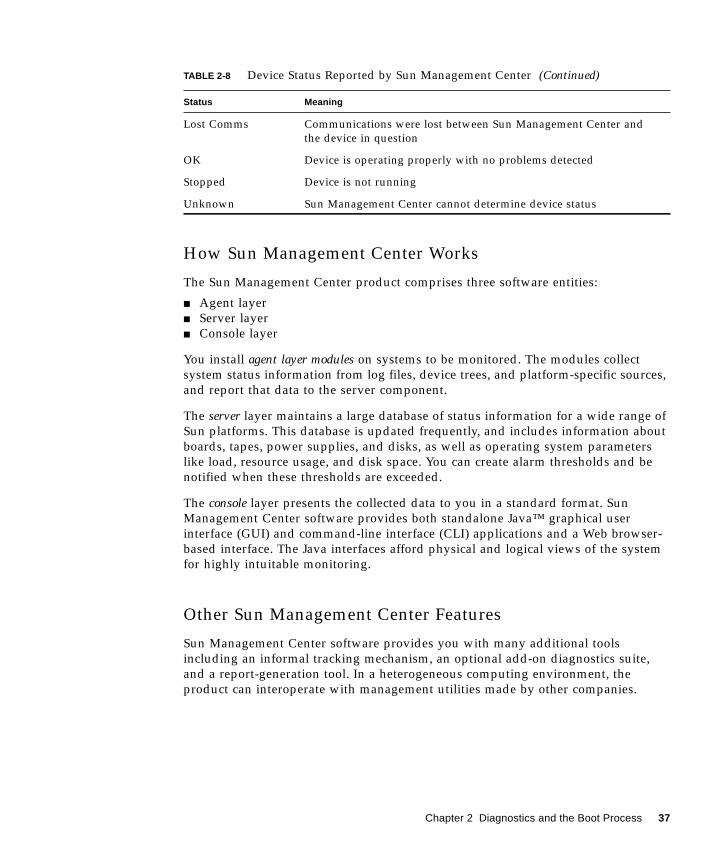
How Sun Management Center Works
The Sun Management Center product comprises three software entities:
■ Agent layer
■ Server layer
■ Console layer
You install agent layer modules on systems to be monitored. The modules collect
system status information from log files, device trees, and platform-specific sources,
and report that data to the server component.
The server layer maintains a large database of status information for a wide range of
Sun platforms. This database is updated frequently, and includes information about
boards, tapes, power supplies, and disks, as well as operating system parameters
like load, resource usage, and disk space. You can create alarm thresholds and be
notified when these thresholds are exceeded.
The console layer presents the collected data to you in a standard format. Sun
Management Center software provides both standalone Java™ graphical user
interface (GUI) and command-line interface (CLI) applications and a Web browser-
based interface. The Java interfaces afford physical and logical views of the system
for highly intuitable monitoring.
Other Sun Management Center Features
Sun Management Center software provides you with many additional tools
including an informal tracking mechanism, an optional add-on diagnostics suite,
and a report-generation tool. In a heterogeneous computing environment, the
product can interoperate with management utilities made by other companies.
Lost Comms Communications were lost between Sun Management Center and
the device in question
OK Device is operating properly with no problems detected
Stopped Device is not running
Unknown Sun Management Center cannot determine device status
TABLE 2-8 Device Status Reported by Sun Management Center (Continued)
Status Meaning
Chapter 2 Diagnostics and the Boot Process 37
Informal Tracking
Sun Management Center agent software must be loaded on any server you want to
monitor. However, the product lets you informally track a supported platform even
when the agent software has not been installed on it. In this case, you do not have
full monitoring capability, but you can add the server to a list in the Sun
Management Center interface, have Sun Management Center periodically check
whether the server is up and running, and notify you if the server stops responding.
Add-On Diagnostic Suite
The Hardware Diagnostic Suite is available as a premium package you can purchase as
an add-on to the Sun Management Center product. This suite lets you exercise a
system while it is still up and running in a production environment. See “Exercising
the System Using the Hardware Diagnostic Suite” on page 42 for more information.
Report Generation Tool
The Performance Reporting Manager is a Sun Management Center add-on that allows
you to create reports detailing the status of your machines. The tool generates report
data on performance, hardware, configurations, software packages, patches, and
alarms for an arbitrary subset of managed systems in your data center.
Interoperability With Third-Party Monitoring Tools
If you administer a heterogeneous network and use a third-party network-based
system monitoring or management tool, you may be able to take advantage of Sun
Management Center software’s support for Tivoli Enterprise Console, BMC Patrol,
and HP Openview.
Who Should Use Sun Management Center?
Sun Management Center software is geared primarily toward system administrators
who have large data centers to monitor or other installations that have many
computer platforms to monitor. If you administer a more modest installation, you
need to weigh Sun Management Center software’s benefits against the requirement
of maintaining a significant database (typically over 700 Mbytes) of system status
information.
38 Sun Fire V440 Server Diagnostics and Troubleshooting Guide • July 2003
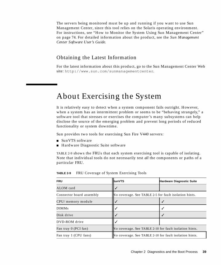
The servers being monitored must be up and running if you want to use Sun
Management Center, since this tool relies on the Solaris operating environment.
For instructions, see “How to Monitor the System Using Sun Management Center”
on page 74. For detailed information about the product, see the Sun ManagementCenter Software User’s Guide.
Obtaining the Latest Information
For the latest information about this product, go to the Sun Management Center Web
site: http://www.sun.com/sunmanagementcenter .
About Exercising the System
It is relatively easy to detect when a system component fails outright. However,
when a system has an intermittent problem or seems to be “behaving strangely,” a
software tool that stresses or exercises the computer’s many subsystems can help
disclose the source of the emerging problem and prevent long periods of reduced
functionality or system downtime.
Sun provides two tools for exercising Sun Fire V440 servers:
■ SunVTS software
■ Hardware Diagnostic Suite software
TABLE 2-9 shows the FRUs that each system exercising tool is capable of isolating.
Note that individual tools do not necessarily test all the components or paths of a
particular FRU.
TABLE 2-9 FRU Coverage of System Exercising Tools
FRU SunVTS Hardware Diagnostic Suite
ALOM card ✓
Connector board assembly No coverage. See TABLE 2-5 for fault isolation hints.
CPU/memory module ✓ ✓
DIMMs ✓ ✓
Disk drive ✓ ✓
DVD-ROM drive ✓
Fan tray 0 (PCI fan) No coverage. See TABLE 2-10 for fault isolation hints.
Fan tray 1 (CPU fans) No coverage. See TABLE 2-10 for fault isolation hints.
Chapter 2 Diagnostics and the Boot Process 39

Some FRUs are not isolated by any system exercising tool.
Exercising the System Using SunVTS Software
SunVTS software validation test suite performs system and subsystem stress testing.
You can view and control a SunVTS session over a network. Using a remote
machine, you can view the progress of a testing session, change testing options, and
control all testing features of another machine on the network.
You can run SunVTS software in five different test modes:
■ Connection mode – SunVTS software verifies the presence of device controllers on
all subsystems. This typically takes no more than a few minutes and is a good
way to “sanity check” system connections.
■ Functional mode – SunVTS software exercises only the specific subsystems you
choose. This is the default mode. In Functional mode, selected tests are run in
parallel. This mode uses system resources heavily, so you should not run any
other applications at the same time.
Motherboard ✓ ✓
Power supply ✓
SCSI backplane ✓
System configuration card reader No coverage. See TABLE 2-5 for fault isolation hints.
System configuration card ✓
TABLE 2-10 FRUs Not Directly Isolated by System Exercising Tools
FRU Diagnostic Hints
Connector board assembly See TABLE 2-5.
DVD/CD-ROM drive cable See TABLE 2-5.
Fan tray 0 (PCI fan) If this FRU fails, ALOM issues an alert message:
SC Alert: PCI_FAN @ FT0 Failed.
Fan tray 1 (CPU fan) If this FRU fails, ALOM issues an alert message:
SC Alert: CPU_FAN @ FT1 Failed.
SCSI data cable See TABLE 2-5.
Connector board power cable See TABLE 2-5.
TABLE 2-9 FRU Coverage of System Exercising Tools (Continued)
FRU SunVTS Hardware Diagnostic Suite
40 Sun Fire V440 Server Diagnostics and Troubleshooting Guide • July 2003
■ Auto Config mode – SunVTS software automatically detects all subsystems and
exercises them in one of two ways:
■ Confidence testing – SunVTS software performs one pass of tests on all
subsystems, and then stops. For typical system configurations, this requires
one or two hours.
■ Comprehensive testing – SunVTS software exhaustively and repeatedly tests all
subsystems for up to 24 hours.
■ Exclusive mode – SunVTS software exercises only the specific subsystems you
choose. Selected tests are run one at a time. A few tests are only available in this
mode, including: l1dcachetest , l2cachetest , l2sramtest , mpconstest ,
mptest , and systest .
■ Online mode – SunVTS software exercises only the specific subsystems you choose.
Selected tests are run one at a time until one complete system pass is achieved.
This mode is useful for performing tests while other applications are running.
Since SunVTS software can run many tests in parallel and can consume many
system resources, you should take care when using it on a production system. If you
are stress-testing a system using SunVTS software’s Comprehensive test mode, you
should not run anything else on that system at the same time.
The Sun Fire V440 server to be tested must be up and running if you want to use
SunVTS software, since it relies on the Solaris operating environment. Since SunVTS
software packages are optional, they may not be installed on your system. Turn to
“How to Check Whether SunVTS Software Is Installed” on page 100 for instructions.
It is important to use the most up-to-date version of SunVTS available, to ensure that
you have the latest suite of tests. To download the most recent SunVTS software,
point your Web browser to: http://www.sun.com/oem/products/vts/ .
For instructions on running SunVTS software to exercise the Sun Fire V440 server,
see “How to Exercise the System Using SunVTS Software” on page 96. For more
information about the product, see:
■ SunVTS User’s Guide – Describes SunVTS features as well as how to start and
control the various user interfaces.
■ SunVTS Test Reference Manual – Describes each SunVTS test, option, and
command-line argument.
■ SunVTS Quick Reference Card – Gives an overview of the main features of the
graphical user interface (GUI).
■ SunVTS Documentation Supplement – Describes the latest product enhancements
and documentation updates not included in the SunVTS User’s Guide and SunVTSTest Reference Manual.
Chapter 2 Diagnostics and the Boot Process 41
These documents are available on the Solaris Supplement CD and on the Web at:
http://www.sun.com/documentation . You should also consult the SunVTS
README file located at /opt/SUNWvts/ . This document provides late-breaking
information about the installed version of the product.
SunVTS Software and Security
During SunVTS software installation, you must choose between Basic or Sun
Enterprise Authentication Mechanism (SEAM) security. Basic security uses a local
security file in the SunVTS installation directory to limit the users, groups, and hosts
permitted to use SunVTS software. SEAM security is based on Kerberos—the
standard network authentication protocol—and provides secure user authentication,
data integrity, and privacy for transactions over networks.
If your site uses SEAM security, you must have the SEAM client and server software
installed in your networked environment and configured properly in both Solaris
and SunVTS software. If your site does not use SEAM security, do not choose the
SEAM option during SunVTS software installation.
If you enable the wrong security scheme during installation, or if you improperly
configure the security scheme you chose, you may find yourself unable to run
SunVTS tests. For more information, see the SunVTS User’s Guide and the
instructions accompanying the SEAM software.
Exercising the System Using the Hardware
Diagnostic Suite
The Sun Management Center product features the optional Hardware Diagnostic
Suite, which you can purchase as an add-on. The Hardware Diagnostic Suite is
designed to exercise a production system by running tests sequentially.
Sequential testing means the Hardware Diagnostic Suite has a low impact on the
system. Unlike SunVTS software, which stresses a server by consuming its resources
with many parallel tests (see “Exercising the System Using SunVTS Software” on
page 40), the Hardware Diagnostic Suite lets the server run other applications while
testing proceeds.
When to Run the Hardware Diagnostic Suite
The best use of the Hardware Diagnostic Suite is to disclose a suspected or
intermittent problem with a noncritical part on an otherwise functioning server.
Examples include questionable disk drives or memory modules on a server that has
ample or redundant disk and memory resources.
42 Sun Fire V440 Server Diagnostics and Troubleshooting Guide • July 2003
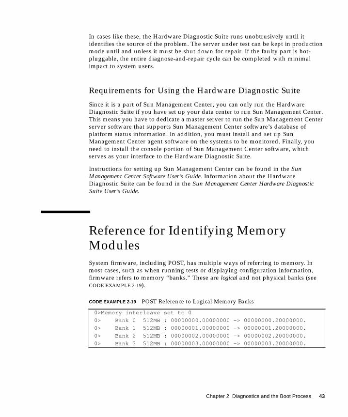
In cases like these, the Hardware Diagnostic Suite runs unobtrusively until it
identifies the source of the problem. The server under test can be kept in production
mode until and unless it must be shut down for repair. If the faulty part is hot-
pluggable, the entire diagnose-and-repair cycle can be completed with minimal
impact to system users.
Requirements for Using the Hardware Diagnostic Suite
Since it is a part of Sun Management Center, you can only run the Hardware
Diagnostic Suite if you have set up your data center to run Sun Management Center.
This means you have to dedicate a master server to run the Sun Management Center
server software that supports Sun Management Center software’s database of
platform status information. In addition, you must install and set up Sun
Management Center agent software on the systems to be monitored. Finally, you
need to install the console portion of Sun Management Center software, which
serves as your interface to the Hardware Diagnostic Suite.
Instructions for setting up Sun Management Center can be found in the SunManagement Center Software User’s Guide. Information about the Hardware
Diagnostic Suite can be found in the Sun Management Center Hardware DiagnosticSuite User’s Guide.
Reference for Identifying MemoryModules
System firmware, including POST, has multiple ways of referring to memory. In
most cases, such as when running tests or displaying configuration information,
firmware refers to memory “banks.” These are logical and not physical banks (see
CODE EXAMPLE 2-19).
CODE EXAMPLE 2-19 POST Reference to Logical Memory Banks
0>Memory interleave set to 0
0> Bank 0 512MB : 00000000.00000000 -> 00000000.20000000.
0> Bank 1 512MB : 00000001.00000000 -> 00000001.20000000.
0> Bank 2 512MB : 00000002.00000000 -> 00000002.20000000.
0> Bank 3 512MB : 00000003.00000000 -> 00000003.20000000.
Chapter 2 Diagnostics and the Boot Process 43
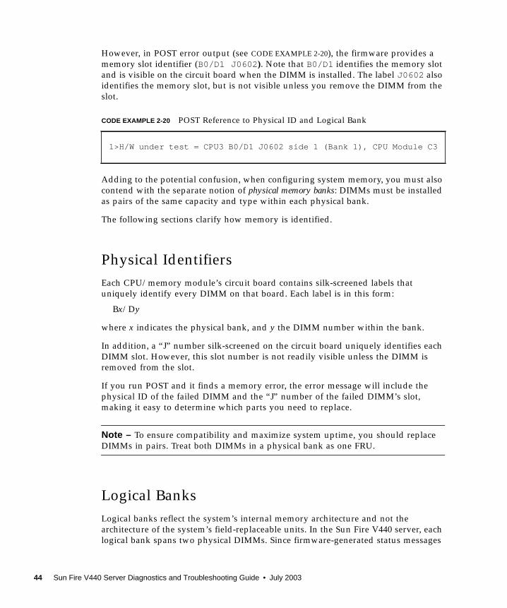
However, in POST error output (see CODE EXAMPLE 2-20), the firmware provides a
memory slot identifier (B0/D1 J0602 ). Note that B0/D1 identifies the memory slot
and is visible on the circuit board when the DIMM is installed. The label J0602 also
identifies the memory slot, but is not visible unless you remove the DIMM from the
slot.
Adding to the potential confusion, when configuring system memory, you must also
contend with the separate notion of physical memory banks: DIMMs must be installed
as pairs of the same capacity and type within each physical bank.
The following sections clarify how memory is identified.
Physical Identifiers
Each CPU/memory module’s circuit board contains silk-screened labels that
uniquely identify every DIMM on that board. Each label is in this form:
Bx/Dy
where x indicates the physical bank, and y the DIMM number within the bank.
In addition, a “J” number silk-screened on the circuit board uniquely identifies each
DIMM slot. However, this slot number is not readily visible unless the DIMM is
removed from the slot.
If you run POST and it finds a memory error, the error message will include the
physical ID of the failed DIMM and the “J” number of the failed DIMM’s slot,
making it easy to determine which parts you need to replace.
Note – To ensure compatibility and maximize system uptime, you should replace
DIMMs in pairs. Treat both DIMMs in a physical bank as one FRU.
Logical Banks
Logical banks reflect the system’s internal memory architecture and not the
architecture of the system’s field-replaceable units. In the Sun Fire V440 server, each
logical bank spans two physical DIMMs. Since firmware-generated status messages
CODE EXAMPLE 2-20 POST Reference to Physical ID and Logical Bank
1>H/W under test = CPU3 B0/D1 J0602 side 1 (Bank 1), CPU Module C3
44 Sun Fire V440 Server Diagnostics and Troubleshooting Guide • July 2003
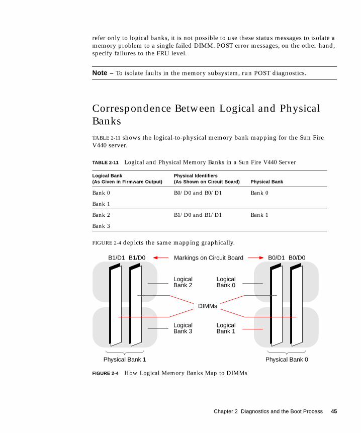
refer only to logical banks, it is not possible to use these status messages to isolate a
memory problem to a single failed DIMM. POST error messages, on the other hand,
specify failures to the FRU level.
Note – To isolate faults in the memory subsystem, run POST diagnostics.
Correspondence Between Logical and Physical
Banks
TABLE 2-11 shows the logical-to-physical memory bank mapping for the Sun Fire
V440 server.
FIGURE 2-4 depicts the same mapping graphically.
FIGURE 2-4 How Logical Memory Banks Map to DIMMs
TABLE 2-11 Logical and Physical Memory Banks in a Sun Fire V440 Server
Logical Bank(As Given in Firmware Output)
Physical Identifiers(As Shown on Circuit Board) Physical Bank
Bank 0 B0/D0 and B0/D1 Bank 0
Bank 1
Bank 2 B1/D0 and B1/D1 Bank 1
Bank 3
LogicalBank 2
LogicalBank 3
LogicalBank 0
LogicalBank 1
Markings on Circuit Board B0/D0B0/D1B1/D0B1/D1
DIMMs
Physical Bank 1 Physical Bank 0
Chapter 2 Diagnostics and the Boot Process 45
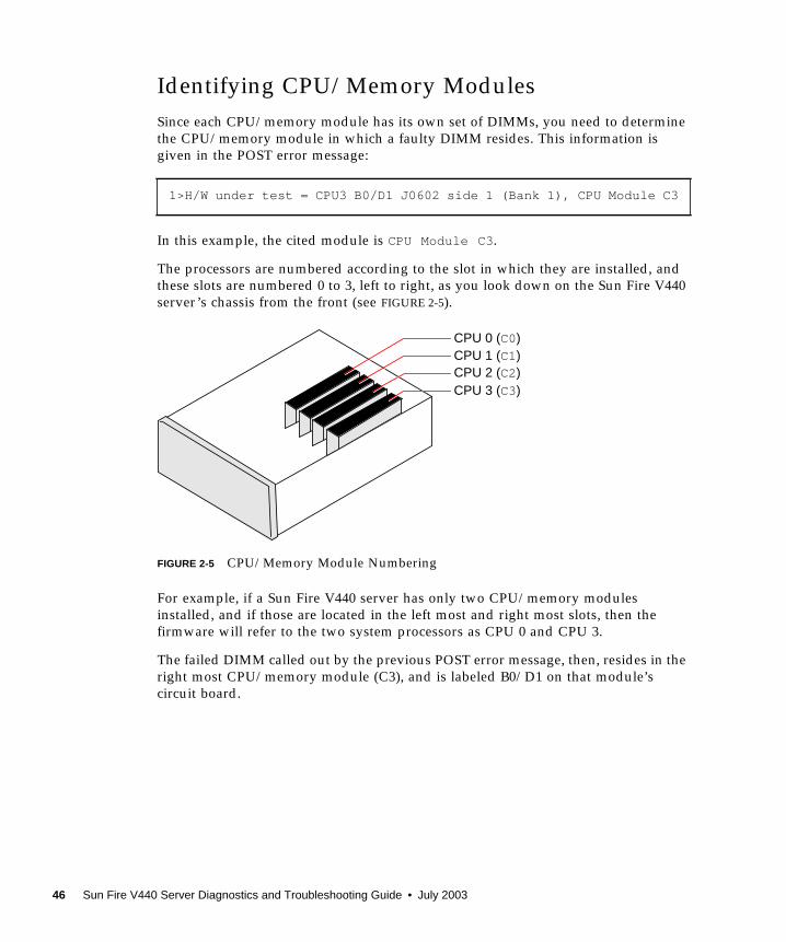
Identifying CPU/Memory Modules
Since each CPU/memory module has its own set of DIMMs, you need to determine
the CPU/memory module in which a faulty DIMM resides. This information is
given in the POST error message:
In this example, the cited module is CPU Module C3.
The processors are numbered according to the slot in which they are installed, and
these slots are numbered 0 to 3, left to right, as you look down on the Sun Fire V440
server’s chassis from the front (see FIGURE 2-5).
FIGURE 2-5 CPU/Memory Module Numbering
For example, if a Sun Fire V440 server has only two CPU/memory modules
installed, and if those are located in the left most and right most slots, then the
firmware will refer to the two system processors as CPU 0 and CPU 3.
The failed DIMM called out by the previous POST error message, then, resides in the
right most CPU/memory module (C3), and is labeled B0/D1 on that module’s
circuit board.
1>H/W under test = CPU3 B0/D1 J0602 side 1 (Bank 1), CPU Module C3
CPU 0 (C0)CPU 1 (C1)CPU 2 (C2)CPU 3 (C3)
46 Sun Fire V440 Server Diagnostics and Troubleshooting Guide • July 2003
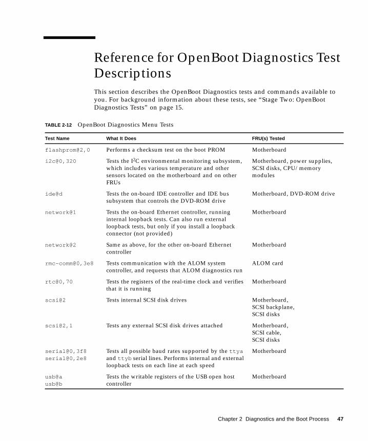
Reference for OpenBoot Diagnostics TestDescriptions
This section describes the OpenBoot Diagnostics tests and commands available to
you. For background information about these tests, see “Stage Two: OpenBoot
Diagnostics Tests” on page 15.
TABLE 2-12 OpenBoot Diagnostics Menu Tests
Test Name What It Does FRU(s) Tested
flashprom@2,0 Performs a checksum test on the boot PROM Motherboard
i2c@0,320 Tests the I2C environmental monitoring subsystem,
which includes various temperature and other
sensors located on the motherboard and on other
FRUs
Motherboard, power supplies,
SCSI disks, CPU/memory
modules
ide@d Tests the on-board IDE controller and IDE bus
subsystem that controls the DVD-ROM drive
Motherboard, DVD-ROM drive
network@1 Tests the on-board Ethernet controller, running
internal loopback tests. Can also run external
loopback tests, but only if you install a loopback
connector (not provided)
Motherboard
network@2 Same as above, for the other on-board Ethernet
controller
Motherboard
rmc-comm@0,3e8 Tests communication with the ALOM system
controller, and requests that ALOM diagnostics run
ALOM card
rtc@0,70 Tests the registers of the real-time clock and verifies
that it is running
Motherboard
scsi@2 Tests internal SCSI disk drives Motherboard,
SCSI backplane,
SCSI disks
scsi@2,1 Tests any external SCSI disk drives attached Motherboard,
SCSI cable,
SCSI disks
serial@0,3f8serial@0,2e8
Tests all possible baud rates supported by the ttyaand ttyb serial lines. Performs internal and external
loopback tests on each line at each speed
Motherboard
usb@ausb@b
Tests the writable registers of the USB open host
controller
Motherboard
Chapter 2 Diagnostics and the Boot Process 47
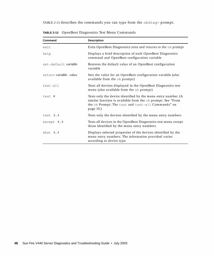
TABLE 2-13 describes the commands you can type from the obdiag> prompt.
TABLE 2-13 OpenBoot Diagnostics Test Menu Commands
Command Description
exit Exits OpenBoot Diagnostics tests and returns to the ok prompt
help Displays a brief description of each OpenBoot Diagnostics
command and OpenBoot configuration variable
set-default variable Restores the default value of an OpenBoot configuration
variable
setenv variable value Sets the value for an OpenBoot configuration variable (also
available from the ok prompt)
test-all Tests all devices displayed in the OpenBoot Diagnostics test
menu (also available from the ok prompt)
test # Tests only the device identified by the menu entry number. (A
similar function is available from the ok prompt. See “From
the ok Prompt: The test and test-all Commands” on
page 19.)
test #,# Tests only the devices identified by the menu entry numbers
except #,# Tests all devices in the OpenBoot Diagnostics test menu except
those identified by the menu entry numbers
what #,# Displays selected properties of the devices identified by the
menu entry numbers. The information provided varies
according to device type
48 Sun Fire V440 Server Diagnostics and Troubleshooting Guide • July 2003
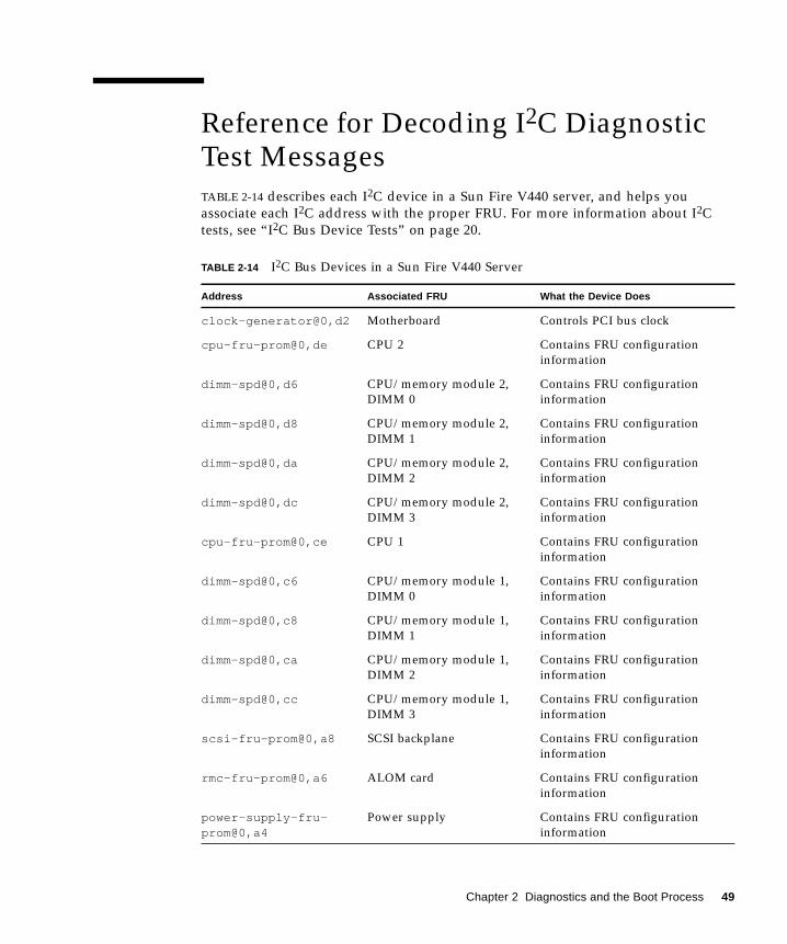
Reference for Decoding I2C DiagnosticTest Messages
TABLE 2-14 describes each I2C device in a Sun Fire V440 server, and helps you
associate each I2C address with the proper FRU. For more information about I2C
tests, see “I2C Bus Device Tests” on page 20.
TABLE 2-14 I2C Bus Devices in a Sun Fire V440 Server
Address Associated FRU What the Device Does
clock-generator@0,d2 Motherboard Controls PCI bus clock
cpu-fru-prom@0,de CPU 2 Contains FRU configuration
information
dimm-spd@0,d6 CPU/memory module 2,
DIMM 0
Contains FRU configuration
information
dimm-spd@0,d8 CPU/memory module 2,
DIMM 1
Contains FRU configuration
information
dimm-spd@0,da CPU/memory module 2,
DIMM 2
Contains FRU configuration
information
dimm-spd@0,dc CPU/memory module 2,
DIMM 3
Contains FRU configuration
information
cpu-fru-prom@0,ce CPU 1 Contains FRU configuration
information
dimm-spd@0,c6 CPU/memory module 1,
DIMM 0
Contains FRU configuration
information
dimm-spd@0,c8 CPU/memory module 1,
DIMM 1
Contains FRU configuration
information
dimm-spd@0,ca CPU/memory module 1,
DIMM 2
Contains FRU configuration
information
dimm-spd@0,cc CPU/memory module 1,
DIMM 3
Contains FRU configuration
information
scsi-fru-prom@0,a8 SCSI backplane Contains FRU configuration
information
rmc-fru-prom@0,a6 ALOM card Contains FRU configuration
information
power-supply-fru-prom@0,a4
Power supply Contains FRU configuration
information
Chapter 2 Diagnostics and the Boot Process 49
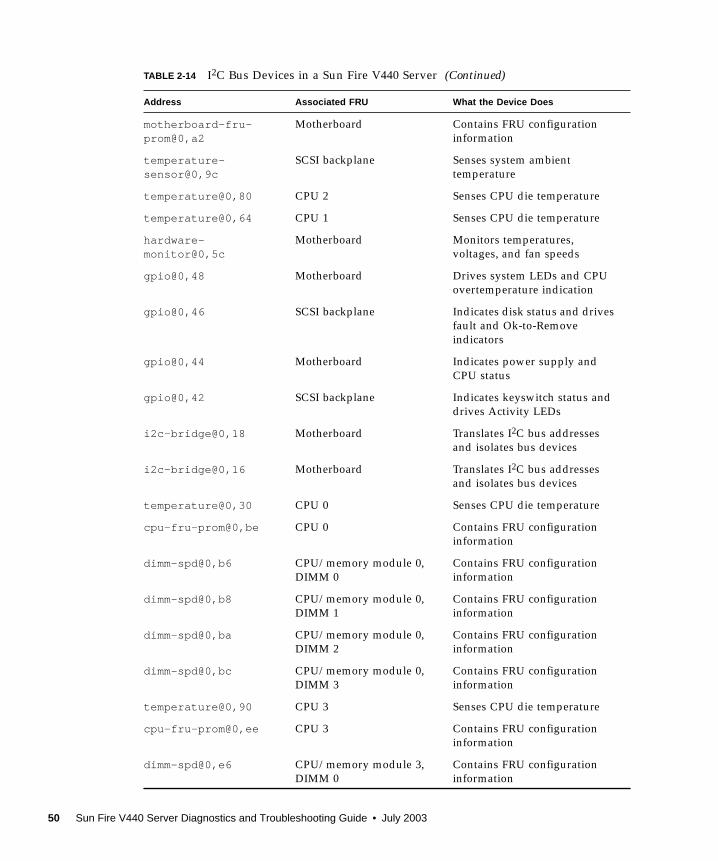
motherboard-fru-prom@0,a2
Motherboard Contains FRU configuration
information
temperature-sensor@0,9c
SCSI backplane Senses system ambient
temperature
temperature@0,80 CPU 2 Senses CPU die temperature
temperature@0,64 CPU 1 Senses CPU die temperature
hardware-monitor@0,5c
Motherboard Monitors temperatures,
voltages, and fan speeds
gpio@0,48 Motherboard Drives system LEDs and CPU
overtemperature indication
gpio@0,46 SCSI backplane Indicates disk status and drives
fault and Ok-to-Remove
indicators
gpio@0,44 Motherboard Indicates power supply and
CPU status
gpio@0,42 SCSI backplane Indicates keyswitch status and
drives Activity LEDs
i2c-bridge@0,18 Motherboard Translates I2C bus addresses
and isolates bus devices
i2c-bridge@0,16 Motherboard Translates I2C bus addresses
and isolates bus devices
temperature@0,30 CPU 0 Senses CPU die temperature
cpu-fru-prom@0,be CPU 0 Contains FRU configuration
information
dimm-spd@0,b6 CPU/memory module 0,
DIMM 0
Contains FRU configuration
information
dimm-spd@0,b8 CPU/memory module 0,
DIMM 1
Contains FRU configuration
information
dimm-spd@0,ba CPU/memory module 0,
DIMM 2
Contains FRU configuration
information
dimm-spd@0,bc CPU/memory module 0,
DIMM 3
Contains FRU configuration
information
temperature@0,90 CPU 3 Senses CPU die temperature
cpu-fru-prom@0,ee CPU 3 Contains FRU configuration
information
dimm-spd@0,e6 CPU/memory module 3,
DIMM 0
Contains FRU configuration
information
TABLE 2-14 I2C Bus Devices in a Sun Fire V440 Server (Continued)
Address Associated FRU What the Device Does
50 Sun Fire V440 Server Diagnostics and Troubleshooting Guide • July 2003
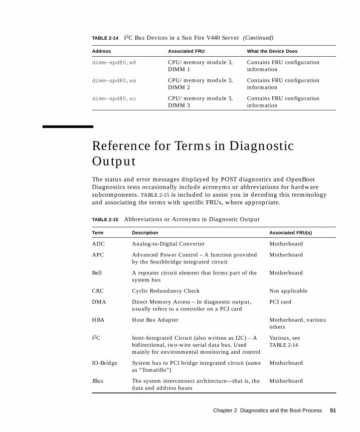
Reference for Terms in DiagnosticOutput
The status and error messages displayed by POST diagnostics and OpenBoot
Diagnostics tests occasionally include acronyms or abbreviations for hardware
subcomponents. TABLE 2-15 is included to assist you in decoding this terminology
and associating the terms with specific FRUs, where appropriate.
dimm-spd@0,e8 CPU/memory module 3,
DIMM 1
Contains FRU configuration
information
dimm-spd@0,ea CPU/memory module 3,
DIMM 2
Contains FRU configuration
information
dimm-spd@0,ec CPU/memory module 3,
DIMM 3
Contains FRU configuration
information
TABLE 2-15 Abbreviations or Acronyms in Diagnostic Output
Term Description Associated FRU(s)
ADC Analog-to-Digital Converter Motherboard
APC Advanced Power Control – A function provided
by the Southbridge integrated circuit
Motherboard
Bell A repeater circuit element that forms part of the
system bus
Motherboard
CRC Cyclic Redundancy Check Not applicable
DMA Direct Memory Access – In diagnostic output,
usually refers to a controller on a PCI card
PCI card
HBA Host Bus Adapter Motherboard, various
others
I2C Inter-Integrated Circuit (also written as I2C) – A
bidirectional, two-wire serial data bus. Used
mainly for environmental monitoring and control
Various, see
TABLE 2-14
IO-Bridge System bus to PCI bridge integrated circuit (same
as “Tomatillo”)
Motherboard
JBus The system interconnect architecture—that is, the
data and address buses
Motherboard
TABLE 2-14 I2C Bus Devices in a Sun Fire V440 Server (Continued)
Address Associated FRU What the Device Does
Chapter 2 Diagnostics and the Boot Process 51
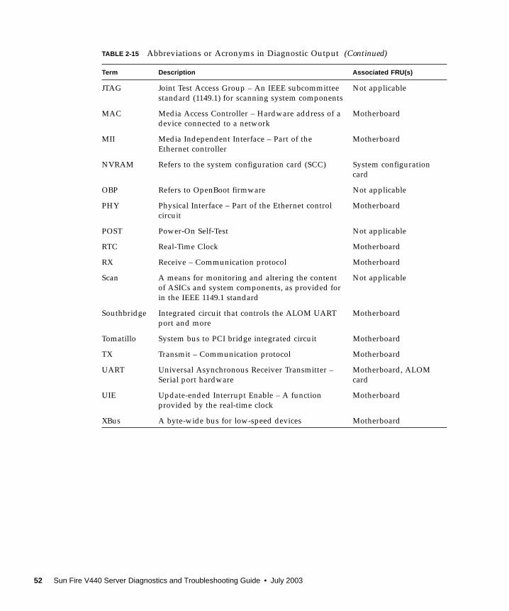
JTAG Joint Test Access Group – An IEEE subcommittee
standard (1149.1) for scanning system components
Not applicable
MAC Media Access Controller – Hardware address of a
device connected to a network
Motherboard
MII Media Independent Interface – Part of the
Ethernet controller
Motherboard
NVRAM Refers to the system configuration card (SCC) System configuration
card
OBP Refers to OpenBoot firmware Not applicable
PHY Physical Interface – Part of the Ethernet control
circuit
Motherboard
POST Power-On Self-Test Not applicable
RTC Real-Time Clock Motherboard
RX Receive – Communication protocol Motherboard
Scan A means for monitoring and altering the content
of ASICs and system components, as provided for
in the IEEE 1149.1 standard
Not applicable
Southbridge Integrated circuit that controls the ALOM UART
port and more
Motherboard
Tomatillo System bus to PCI bridge integrated circuit Motherboard
TX Transmit – Communication protocol Motherboard
UART Universal Asynchronous Receiver Transmitter –
Serial port hardware
Motherboard, ALOM
card
UIE Update-ended Interrupt Enable – A function
provided by the real-time clock
Motherboard
XBus A byte-wide bus for low-speed devices Motherboard
TABLE 2-15 Abbreviations or Acronyms in Diagnostic Output (Continued)
Term Description Associated FRU(s)
52 Sun Fire V440 Server Diagnostics and Troubleshooting Guide • July 2003
CHAPTER 3
Isolating Failed Parts
The most important use of diagnostic tools is to isolate a failed hardware component
so that you can quickly remove and replace it. Because servers are complex
machines with many failure modes, there is no single diagnostic tool that can isolate
all hardware faults under all conditions. However, Sun provides a variety of tools
that can help you discern what component needs replacing.
This chapter guides you in choosing the best tools and describes how to use these
tools to reveal a failed part in your Sun Fire V440 server. It also explains how to use
the Locator LED to isolate a failed system in a large equipment room.
Tasks covered in this chapter include:
■ “How to View and Set OpenBoot Configuration Variables” on page 54
■ “How to Operate the Locator LED” on page 55
■ “How to Put the System in Diagnostics Mode” on page 57
■ “How to Bypass Firmware Diagnostics” on page 58
■ “How to Bypass Diagnostics Temporarily” on page 59
■ “How to Maximize Diagnostic Testing” on page 61
■ “How to Isolate Faults Using LEDs” on page 62
■ “How to Isolate Faults Using POST Diagnostics” on page 65
■ “How to Isolate Faults Using Interactive OpenBoot Diagnostics Tests” on page 67
■ “How to View Diagnostic Test Results After the Fact” on page 70
Other information in this chapter includes:
■ “Reference for Choosing a Fault Isolation Tool” on page 70
If you want background information about the tools, turn to the section:
■ “About Isolating Faults in the System” on page 32
Note – Many of the procedures in this chapter assume that you are familiar with the
OpenBoot firmware and that you know how to access the ok prompt. For
background information, see “About the ok Prompt” on page 171. For instructions,
see “How to Get to the ok Prompt” on page 176.
53
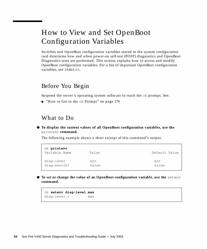
How to View and Set OpenBootConfiguration Variables
Switches and OpenBoot configuration variables stored in the system configuration
card determine how and when power-on self-test (POST) diagnostics and OpenBoot
Diagnostics tests are performed. This section explains how to access and modify
OpenBoot configuration variables. For a list of important OpenBoot configuration
variables, see TABLE 2-1.
Before You Begin
Suspend the server’s operating system software to reach the ok prompt. See:
■ “How to Get to the ok Prompt” on page 176
What to Do
● To display the current values of all OpenBoot configuration variables, use theprintenv command.
The following example shows a short excerpt of this command’s output.
● To set or change the value of an OpenBoot configuration variable, use the setenvcommand.
ok printenvVariable Name Value Default Value
diag-level min mindiag-switch? false false
ok setenv diag-level maxdiag-level = max
54 Sun Fire V440 Server Diagnostics and Troubleshooting Guide • July 2003
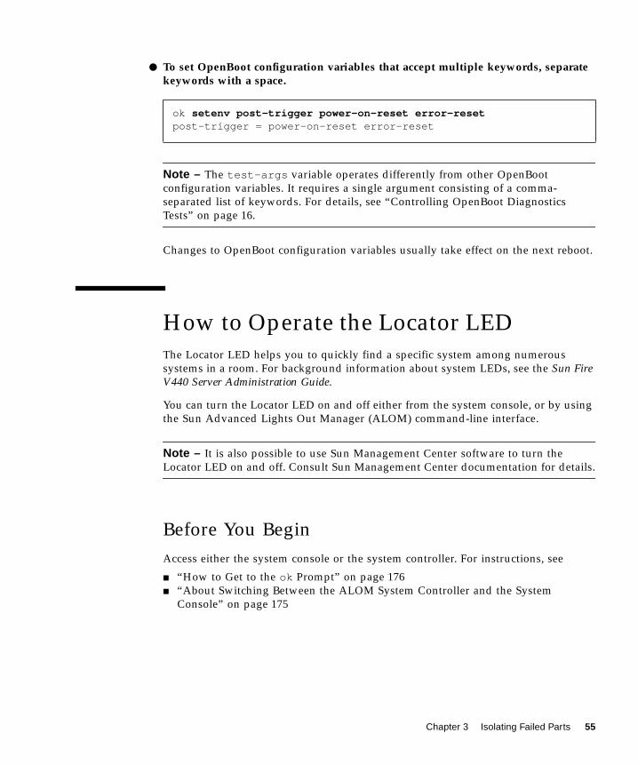
● To set OpenBoot configuration variables that accept multiple keywords, separatekeywords with a space.
Note – The test-args variable operates differently from other OpenBoot
configuration variables. It requires a single argument consisting of a comma-
separated list of keywords. For details, see “Controlling OpenBoot Diagnostics
Tests” on page 16.
Changes to OpenBoot configuration variables usually take effect on the next reboot.
How to Operate the Locator LED
The Locator LED helps you to quickly find a specific system among numerous
systems in a room. For background information about system LEDs, see the Sun FireV440 Server Administration Guide.
You can turn the Locator LED on and off either from the system console, or by using
the Sun Advanced Lights Out Manager (ALOM) command-line interface.
Note – It is also possible to use Sun Management Center software to turn the
Locator LED on and off. Consult Sun Management Center documentation for details.
Before You Begin
Access either the system console or the system controller. For instructions, see
■ “How to Get to the ok Prompt” on page 176
■ “About Switching Between the ALOM System Controller and the System
Console” on page 175
ok setenv post-trigger power-on-reset error-resetpost-trigger = power-on-reset error-reset
Chapter 3 Isolating Failed Parts 55
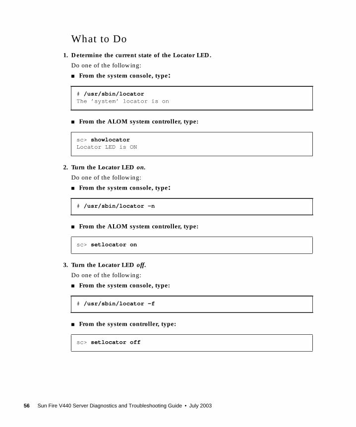
What to Do
1. Determine the current state of the Locator LED.
Do one of the following:
■ From the system console, type:
■ From the ALOM system controller, type:
2. Turn the Locator LED on.
Do one of the following:
■ From the system console, type:
■ From the ALOM system controller, type:
3. Turn the Locator LED off.
Do one of the following:
■ From the system console, type:
■ From the system controller, type:
# /usr/sbin/locatorThe ’system’ locator is on
sc> showlocatorLocator LED is ON
# /usr/sbin/locator -n
sc> setlocator on
# /usr/sbin/locator -f
sc> setlocator off
56 Sun Fire V440 Server Diagnostics and Troubleshooting Guide • July 2003
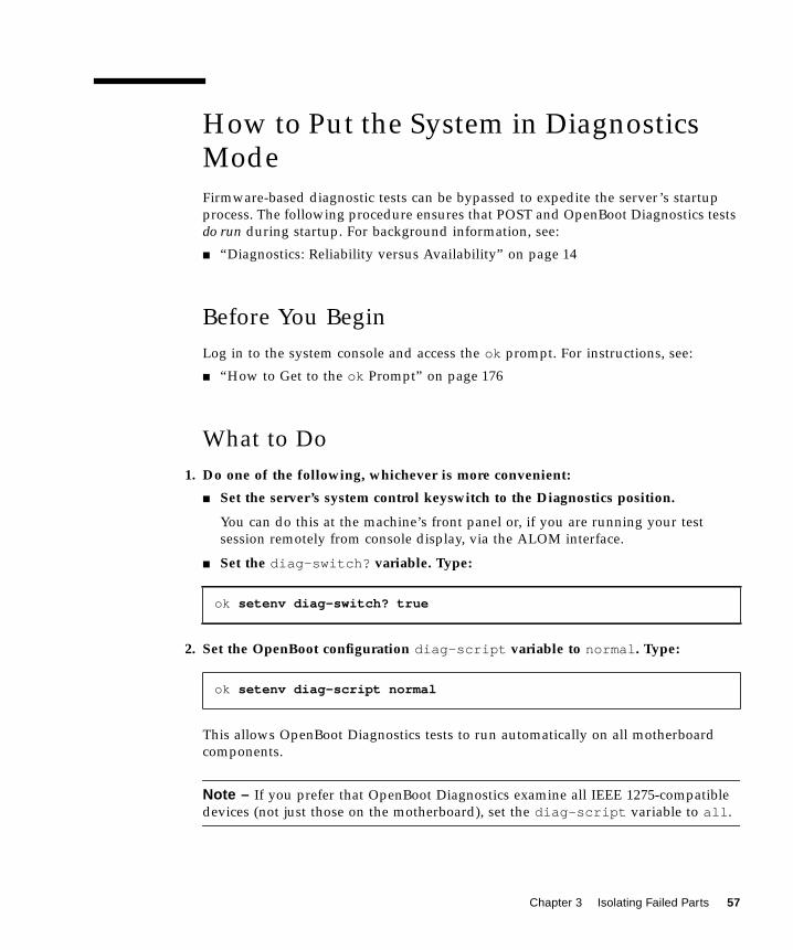
How to Put the System in DiagnosticsMode
Firmware-based diagnostic tests can be bypassed to expedite the server’s startup
process. The following procedure ensures that POST and OpenBoot Diagnostics tests
do run during startup. For background information, see:
■ “Diagnostics: Reliability versus Availability” on page 14
Before You Begin
Log in to the system console and access the ok prompt. For instructions, see:
■ “How to Get to the ok Prompt” on page 176
What to Do
1. Do one of the following, whichever is more convenient:
■ Set the server’s system control keyswitch to the Diagnostics position.
You can do this at the machine’s front panel or, if you are running your test
session remotely from console display, via the ALOM interface.
■ Set the diag-switch? variable. Type:
2. Set the OpenBoot configuration diag-script variable to normal . Type:
This allows OpenBoot Diagnostics tests to run automatically on all motherboard
components.
Note – If you prefer that OpenBoot Diagnostics examine all IEEE 1275-compatible
devices (not just those on the motherboard), set the diag-script variable to all .
ok setenv diag-switch? true
ok setenv diag-script normal
Chapter 3 Isolating Failed Parts 57

3. Set OpenBoot configuration variables to trigger diagnostic tests. Type:
4. Set the maximum POST diagnostic test level. Type:
This ensures the most thorough power-on self-test possible. The maximum testing
level requires considerably longer to complete than the minimum. Depending on
system configuration, you may need to wait an additional 10 to 20 minutes for the
server to boot.
How to Bypass Firmware Diagnostics
POST and OpenBoot Diagnostics tests can be bypassed to expedite the server’s
startup process. For background information, see:
■ “Diagnostics: Reliability versus Availability” on page 14
Caution – Bypassing diagnostic tests sacrifices system reliability by allowing a
system to attempt to boot when it may have a serious hardware problem.
Before You Begin
Log in to the system console and access the ok prompt. For instructions, see:
■ “How to Get to the ok Prompt” on page 176
What to Do
1. Make sure that the server’s system control keyswitch is set to the Normal position.
Setting the keyswitch to the Diagnostics position overrides the OpenBoot
configuration variable settings and causes diagnostic tests to run.
ok setenv post-trigger power-on-reset error-resetok setenv obdiag-trigger power-on-reset error-reset
ok setenv diag-level max
58 Sun Fire V440 Server Diagnostics and Troubleshooting Guide • July 2003
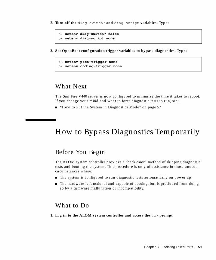
2. Turn off the diag-switch? and diag-script variables. Type:
3. Set OpenBoot configuration trigger variables to bypass diagnostics. Type:
What Next
The Sun Fire V440 server is now configured to minimize the time it takes to reboot.
If you change your mind and want to force diagnostic tests to run, see:
■ “How to Put the System in Diagnostics Mode” on page 57
How to Bypass Diagnostics Temporarily
Before You Begin
The ALOM system controller provides a “back-door” method of skipping diagnostic
tests and booting the system. This procedure is only of assistance in those unusual
circumstances where:
■ The system is configured to run diagnostic tests automatically on power up.
■ The hardware is functional and capable of booting, but is precluded from doing
so by a firmware malfunction or incompatibility.
What to Do
1. Log in to the ALOM system controller and access the sc> prompt.
ok setenv diag-switch? falseok setenv diag-script none
ok setenv post-trigger noneok setenv obdiag-trigger none
Chapter 3 Isolating Failed Parts 59
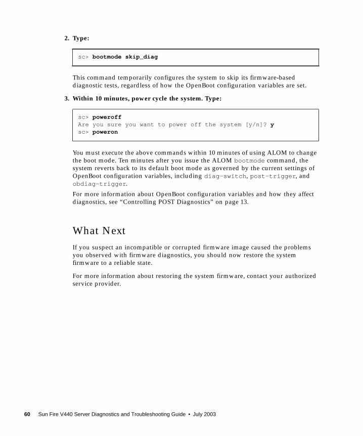
2. Type:
This command temporarily configures the system to skip its firmware-based
diagnostic tests, regardless of how the OpenBoot configuration variables are set.
3. Within 10 minutes, power cycle the system. Type:
You must execute the above commands within 10 minutes of using ALOM to change
the boot mode. Ten minutes after you issue the ALOM bootmode command, the
system reverts back to its default boot mode as governed by the current settings of
OpenBoot configuration variables, including diag-switch , post-trigger , and
obdiag-trigger .
For more information about OpenBoot configuration variables and how they affect
diagnostics, see “Controlling POST Diagnostics” on page 13.
What Next
If you suspect an incompatible or corrupted firmware image caused the problems
you observed with firmware diagnostics, you should now restore the system
firmware to a reliable state.
For more information about restoring the system firmware, contact your authorized
service provider.
sc> bootmode skip_diag
sc> poweroffAre you sure you want to power off the system [y/n]? ysc> poweron
60 Sun Fire V440 Server Diagnostics and Troubleshooting Guide • July 2003
How to Maximize Diagnostic Testing
To maximize system reliability, it is useful to have POST and OpenBoot Diagnostics
tests trigger in the event of an operating system panic or any reset, and to run
automatically the most comprehensive tests possible. For background information,
see:
■ “Diagnostics: Reliability versus Availability” on page 14
Before You Begin
Log in to the system console and access the ok prompt. For instructions, see:
■ “How to Get to the ok Prompt” on page 176
What to Do
1. Do one of the following, whichever is more convenient:
■ Set the server’s system control keyswitch to the Diagnostics position.
You can do this at the server’s front panel or, if you are running your test session
remotely from console display, via the ALOM interface.
■ Set the diag-switch? variable to true . Type:
2. Set the OpenBoot configuration diag-script variable to all . Type:
This allows OpenBoot Diagnostics tests to run automatically on all motherboard
components and IEEE 1275-compatible devices.
Note – If you prefer that OpenBoot Diagnostics examine only motherboard-based
devices, set the diag-script variable to normal .
ok setenv diag-switch? true
ok setenv diag-script all
Chapter 3 Isolating Failed Parts 61
3. Set OpenBoot configuration variables to trigger diagnostic tests. Type:
4. Set the maximum POST diagnostic test level. Type:
This ensures the most thorough testing possible. The maximum testing level requires
considerably longer to complete than the minimum. Depending on system
configuration, you may need to wait an additional 10 to 20 minutes for the server to
boot.
How to Isolate Faults Using LEDs
While not a comprehensive diagnostic tool, LEDs located on the chassis and on
selected system components can serve as front-line indicators of a limited set of
hardware failures.
Before You Begin
You can view LED status by direct inspection of the system’s front and back panels.
You can also view the status of certain LEDs from the ALOM system controller
command-line interface.
Note – Most LEDs available on the front panel are also duplicated on the back
panel.
You can also view LED status remotely using Sun Management Center software, if
you set up this tool ahead of time. For details on setting up Sun Management Center
software, see:
■ Sun Management Center Software User’s Guide
ok setenv post-trigger all-resetsok setenv obdiag-trigger all-resets
ok setenv diag-level max
62 Sun Fire V440 Server Diagnostics and Troubleshooting Guide • July 2003

What to Do
1. Check the system LEDs.
There is a group of three LEDs located near the top left corner of the front panel and
duplicated on the back panel. Their status can tell you the following.
The Locator and Service Required LEDs are powered by the system’s 5-volt standby
power source and remain lit for any fault condition that results in a system
shutdown.
Note – To view the status of system LEDs from ALOM, type showenvironmentfrom the sc> prompt.
2. Check the power supply LEDs.
Each power supply has a set of four LEDs located on the front panel and duplicated
on the back panel. Their status can tell you the following.
LED Name(location; color) Indicates Action
Locator
(left; white)
A system administrator can
turn this on to flag a system
that needs attention.
Identify a particular system
among many.
Service Required
(middle; amber)
If lit, hardware or software has
detected a problem with the
system.
Check other LEDs or run
diagnostics to determine the
problem source.
System Activity
(right; green)
If blinking, operating system
is in the process of booting.
If off, operating system has
stopped.
Not applicable.
LED Name(location; color) Indicates Action
OK-to-Remove
(top; blue)
If lit, power supply can safely
be removed.
Remove power supply as
needed.
Note: Remove a failed power supply only when you are ready
to install its replacement. Both power supplies must remain in
place to ensure proper air circulation and chassis cooling.
Chapter 3 Isolating Failed Parts 63
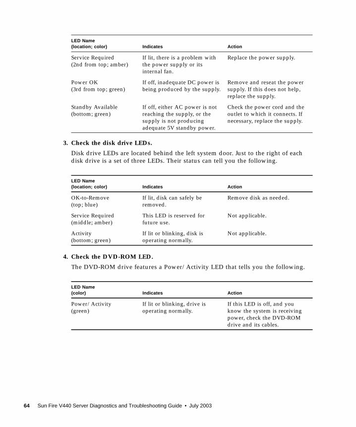
3. Check the disk drive LEDs.
Disk drive LEDs are located behind the left system door. Just to the right of each
disk drive is a set of three LEDs. Their status can tell you the following.
4. Check the DVD-ROM LED.
The DVD-ROM drive features a Power/Activity LED that tells you the following.
Service Required
(2nd from top; amber)
If lit, there is a problem with
the power supply or its
internal fan.
Replace the power supply.
Power OK
(3rd from top; green)
If off, inadequate DC power is
being produced by the supply.
Remove and reseat the power
supply. If this does not help,
replace the supply.
Standby Available
(bottom; green)
If off, either AC power is not
reaching the supply, or the
supply is not producing
adequate 5V standby power.
Check the power cord and the
outlet to which it connects. If
necessary, replace the supply.
LED Name(location; color) Indicates Action
OK-to-Remove
(top; blue)
If lit, disk can safely be
removed.
Remove disk as needed.
Service Required
(middle; amber)
This LED is reserved for
future use.
Not applicable.
Activity
(bottom; green)
If lit or blinking, disk is
operating normally.
Not applicable.
LED Name(color) Indicates Action
Power/Activity
(green)
If lit or blinking, drive is
operating normally.
If this LED is off, and you
know the system is receiving
power, check the DVD-ROM
drive and its cables.
LED Name(location; color) Indicates Action
64 Sun Fire V440 Server Diagnostics and Troubleshooting Guide • July 2003
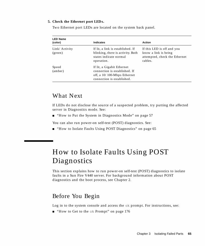
5. Check the Ethernet port LEDs.
Two Ethernet port LEDs are located on the system back panel.
What Next
If LEDs do not disclose the source of a suspected problem, try putting the affected
server in Diagnostics mode. See:
■ “How to Put the System in Diagnostics Mode” on page 57
You can also run power-on self-test (POST) diagnostics. See:
■ “How to Isolate Faults Using POST Diagnostics” on page 65
How to Isolate Faults Using POSTDiagnostics
This section explains how to run power-on self-test (POST) diagnostics to isolate
faults in a Sun Fire V440 server. For background information about POST
diagnostics and the boot process, see Chapter 2.
Before You Begin
Log in to the system console and access the ok prompt. For instructions, see:
■ “How to Get to the ok Prompt” on page 176
LED Name(color) Indicates Action
Link/Activity
(green)
If lit, a link is established. If
blinking, there is activity. Both
states indicate normal
operation.
If this LED is off and you
know a link is being
attempted, check the Ethernet
cables.
Speed
(amber)
If lit, a Gigabit Ethernet
connection is established. If
off, a 10/100-Mbps Ethernet
connection is established.
Chapter 3 Isolating Failed Parts 65
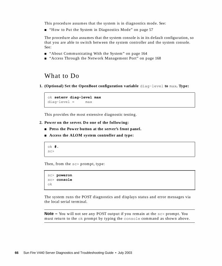
This procedure assumes that the system is in diagnostics mode. See:
■ “How to Put the System in Diagnostics Mode” on page 57
The procedure also assumes that the system console is in its default configuration, so
that you are able to switch between the system controller and the system console.
See:
■ “About Communicating With the System” on page 164
■ “Access Through the Network Management Port” on page 168
What to Do
1. (Optional) Set the OpenBoot configuration variable diag-level to max. Type:
This provides the most extensive diagnostic testing.
2. Power on the server. Do one of the following:
■ Press the Power button at the server’s front panel.
■ Access the ALOM system controller and type:
Then, from the sc> prompt, type:
The system runs the POST diagnostics and displays status and error messages via
the local serial terminal.
Note – You will not see any POST output if you remain at the sc> prompt. You
must return to the ok prompt by typing the console command as shown above.
ok setenv diag-level maxdiag-level = max
ok #.sc>
sc> poweronsc> consoleok
66 Sun Fire V440 Server Diagnostics and Troubleshooting Guide • July 2003
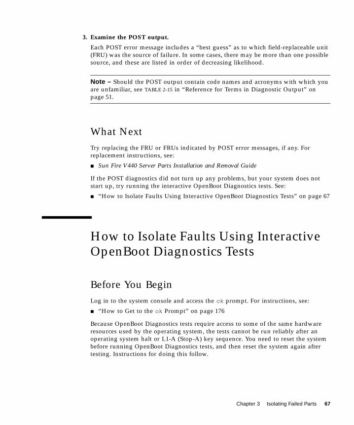
3. Examine the POST output.
Each POST error message includes a “best guess” as to which field-replaceable unit
(FRU) was the source of failure. In some cases, there may be more than one possible
source, and these are listed in order of decreasing likelihood.
Note – Should the POST output contain code names and acronyms with which you
are unfamiliar, see TABLE 2-15 in “Reference for Terms in Diagnostic Output” on
page 51.
What Next
Try replacing the FRU or FRUs indicated by POST error messages, if any. For
replacement instructions, see:
■ Sun Fire V440 Server Parts Installation and Removal Guide
If the POST diagnostics did not turn up any problems, but your system does not
start up, try running the interactive OpenBoot Diagnostics tests. See:
■ “How to Isolate Faults Using Interactive OpenBoot Diagnostics Tests” on page 67
How to Isolate Faults Using InteractiveOpenBoot Diagnostics Tests
Before You Begin
Log in to the system console and access the ok prompt. For instructions, see:
■ “How to Get to the ok Prompt” on page 176
Because OpenBoot Diagnostics tests require access to some of the same hardware
resources used by the operating system, the tests cannot be run reliably after an
operating system halt or L1-A (Stop-A) key sequence. You need to reset the system
before running OpenBoot Diagnostics tests, and then reset the system again after
testing. Instructions for doing this follow.
Chapter 3 Isolating Failed Parts 67
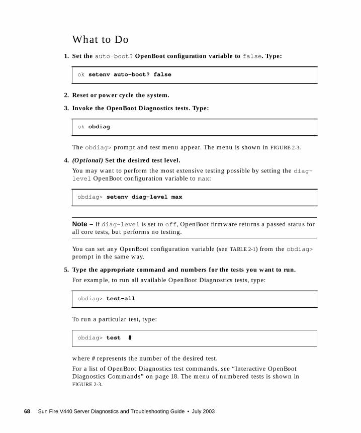
What to Do
1. Set the auto-boot? OpenBoot configuration variable to false . Type:
2. Reset or power cycle the system.
3. Invoke the OpenBoot Diagnostics tests. Type:
The obdiag> prompt and test menu appear. The menu is shown in FIGURE 2-3.
4. (Optional) Set the desired test level.
You may want to perform the most extensive testing possible by setting the diag-level OpenBoot configuration variable to max:
Note – If diag-level is set to off , OpenBoot firmware returns a passed status for
all core tests, but performs no testing.
You can set any OpenBoot configuration variable (see TABLE 2-1) from the obdiag>prompt in the same way.
5. Type the appropriate command and numbers for the tests you want to run.
For example, to run all available OpenBoot Diagnostics tests, type:
To run a particular test, type:
where # represents the number of the desired test.
For a list of OpenBoot Diagnostics test commands, see “Interactive OpenBoot
Diagnostics Commands” on page 18. The menu of numbered tests is shown in
FIGURE 2-3.
ok setenv auto-boot? false
ok obdiag
obdiag> setenv diag-level max
obdiag> test-all
obdiag> test #
68 Sun Fire V440 Server Diagnostics and Troubleshooting Guide • July 2003

6. When you are done running OpenBoot Diagnostics tests, exit the test menu. Type:
The ok prompt reappears.
7. Set the auto-boot? OpenBoot configuration variable back to true . Type:
This allows the operating system to resume starting up automatically after future
system resets or power cycles.
8. To reboot the system, type:
The system stores the OpenBoot configuration variable settings and boots
automatically when the auto-boot? variable is set to true .
What Next
Try replacing the FRU or FRUs indicated by OpenBoot Diagnostics error messages,
if any. For FRU replacement instructions, see:
■ Sun Fire V440 Server Parts Installation and Removal Guide
obdiag> exit
ok setenv auto-boot? true
ok reset-all
Chapter 3 Isolating Failed Parts 69

How to View Diagnostic Test ResultsAfter the Fact
Summaries of the results from the most recent power-on self-test (POST) and
OpenBoot Diagnostics tests are saved across power cycles.
Before You Begin
Log in to the system console and access the ok prompt. For instructions, see:
■ “How to Get to the ok Prompt” on page 176
What to Do
● To see a summary of the last execution of POST diagnostics, type:
● To see a summary of the last execution of OpenBoot Diagnostics tests, type:
You should see a system-dependent list of hardware components, along with an
indication of which components passed and which failed POST or OpenBoot
Diagnostics tests.
Reference for Choosing a Fault IsolationTool
This section helps you choose the right tool to isolate a failed part in a Sun Fire V440
server. Consider the following questions when selecting a tool.
1. Have you checked the LEDs?
ok show-post-results
ok show-obdiag-results
70 Sun Fire V440 Server Diagnostics and Troubleshooting Guide • July 2003
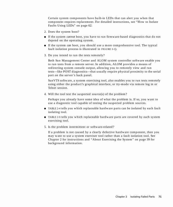
Certain system components have built-in LEDs that can alert you when that
component requires replacement. For detailed instructions, see “How to Isolate
Faults Using LEDs” on page 62.
2. Does the system boot?
■ If the system cannot boot, you have to run firmware-based diagnostics that do not
depend on the operating system.
■ If the system can boot, you should use a more comprehensive tool. The typical
fault isolation process is illustrated in FIGURE 3-1).
3. Do you intend to run the tests remotely?
Both Sun Management Center and ALOM system controller software enable you
to run tests from a remote server. In addition, ALOM provides a means of
redirecting system console output, allowing you to remotely view and run
tests—like POST diagnostics—that usually require physical proximity to the serial
port on the server’s back panel.
SunVTS software, a system exercising tool, also enables you to run tests remotely
using either the product’s graphical interface, or tty-mode via remote log in or
Telnet session.
4. Will the tool test the suspected source(s) of the problem?
Perhaps you already have some idea of what the problem is. If so, you want to
use a diagnostic tool capable of testing the suspected problem sources.
■ TABLE 2-4 tells you which replaceable hardware parts can be isolated by each fault
isolating tool.
■ TABLE 2-9 tells you which replaceable hardware parts are covered by each system
exercising tool.
5. Is the problem intermittent or software-related?
If a problem is not caused by a clearly defective hardware component, then you
may want to use a system exerciser tool rather than a fault isolation tool. See
Chapter 2 for instructions and “About Exercising the System” on page 39 for
background information.
Chapter 3 Isolating Failed Parts 71
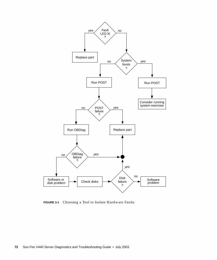
FIGURE 3-1 Choosing a Tool to Isolate Hardware Faults
Systemboots
?
Run POST
yesno
POSTfailure
?
yesno
Replace partRun OBDiag
OBDiagfailure
?
yes
yes noLED litFault
?
Diskfailure
?
yes
noSoftwareproblem
no
disk problemSoftware or
system exerciserConsider running
Replace part
Check disks
Run POST
72 Sun Fire V440 Server Diagnostics and Troubleshooting Guide • July 2003
CHAPTER 4
Monitoring the System
When something goes wrong with the system, diagnostic tools can help you figure
out what caused the problem. Indeed, this is the principal use of most diagnostic
tools. However, this approach is inherently reactive. It means waiting until a
component fails outright.
Some diagnostic tools allow you to be more proactive by monitoring the system
while it is still “healthy.” Monitoring tools give administrators early warning of
imminent failure, thereby allowing planned maintenance and better system
availability. Remote monitoring also allows administrators the convenience of
checking on the status of many machines from one centralized location.
Sun provides two tools that you can use to monitor servers:
■ Sun Management Center
■ Sun Advanced Lights Out Manager (ALOM)
In addition to these tools, Sun provides software-based and firmware-based
commands that display various kinds of system information. While not strictly a
monitoring tool, these commands enable you to review at a glance the status of
different system aspects and components.
This chapter describes the tasks necessary to use these tools to monitor your Sun
Fire V440 server.
Tasks covered in this chapter include:
■ “How to Monitor the System Using Sun Management Center” on page 74
■ “How to Monitor the System Using Sun Advanced Lights Out Manager” on
page 79
■ “How to Use Solaris System Information Commands” on page 93
■ “How to Use OpenBoot Information Commands” on page 94
If you want background information about the tools, turn to Chapter 2.
73
Note – Many of the procedures in this chapter assume that you are familiar with the
OpenBoot firmware and that you know how to access the ok prompt. For
background information, see “About the ok Prompt” on page 171. For instructions,
see “How to Get to the ok Prompt” on page 176.
How to Monitor the System UsingSun Management Center
Sun Management Center software is a flexible product with many features and
options. How you use it depends on the specifics of your network as well as your
needs and preferences. You must decide what role or roles you want your Sun Fire
V440 system to play within the Sun Management Center domain. See “Monitoring
the System Using Sun Management Center” on page 36 for details.
Before You Begin
This procedure assumes that you intend to load Sun Management Center agent
software on the Sun Fire V440 system so as to be able to monitor it, and gives you
some guidance on how to accomplish this goal.
This procedure also assumes that you have set up or will set up one or more
computers to function as Sun Management Center servers and consoles. Servers and
consoles are part of the infrastructure that enables you to monitor systems using Sun
Management Center software. Typically, you would install the server and console
software on machines other than the Sun Fire V440 systems you intend to monitor.
For details, see:
■ Sun Management Center Software User’s Guide
To complete this procedure, you need both the original Sun Management Center
software distribution, and the appropriate supplement for the Sun Fire V440 system.
You can download the latter from the Web as described in the procedure.
If you intend to set up your Sun Fire V440 system as a Sun Management Center
server or console, see:
■ Sun Management Center Software Installation Guide■ Sun Management Center Software User’s Guide
Also see the other documents accompanying the Sun Management Center software.
74 Sun Fire V440 Server Diagnostics and Troubleshooting Guide • July 2003
Note – Sun Management Center software provides both standalone and browser-
based console interfaces. This procedure assumes that you are using the standalone
Java technology-based graphical console. The Web browser console interface, which
differs somewhat in design and capabilities, is covered in the Sun Management CenterSoftware User’s Guide.
What to Do
1. Download the correct Sun Management Center supplement for the Sun Fire V440system.
Look for the Sun Management Center 3.x Supplement for Sun Fire, Sun Blade and NetraSystems, available for free download from this Web site:
http://www.sun.com/sunmanagementcenter
2. On the Sun Fire V440 system, install Sun Management Center agent software.
You must install the agent components from both the original Sun Management
Center distribution, and from the supplement. For instructions, see the
documentation accompanying the distribution and the supplement.
3. On the Sun Fire V440 system, run the setup utility to configure agent software.
The setup utility is part of the Sun Management Center distribution. For more
information, see the Sun Management Center Software User’s Guide.
4. On the Sun Management Center server, install the supplement software.
You must install the server supplement components in order to monitor a Sun Fire
V440 system.
5. On the Sun Management Center server, run the setup utility.
The setup utility is part of the Sun Management Center distribution. For more
information, see the Sun Management Center Software User’s Guide.
6. On the Sun Management Center server, add the Sun Fire V440 system to anadministrative domain.
You can do this automatically using the Discovery Manager tool, or manually by
creating an object from the console’s Edit menu. For specific instructions, see the SunManagement Center Software User’s Guide.
7. On a Sun Management Center console, double-click the icon representing the SunFire V440 system.
The Details window appears.
Chapter 4 Monitoring the System 75

8. Click the Hardware tab.
9. Monitor the Sun Fire V440 system using physical and logical views.
a. Select “Physical View: system” from the Views menu.
The physical view lets you interact with photo-realistic views of the Sun Fire V440
system as seen from the front, rear, and top. As you highlight individual
hardware components and features, status and manufacturing information about
each component appears to the right.
Details window
Hardware tab
Views menu
Physical and logical views
Highlighted component
Information about
Photo-realistic view (front)
(disk drive)
disk drive
76 Sun Fire V440 Server Diagnostics and Troubleshooting Guide • July 2003
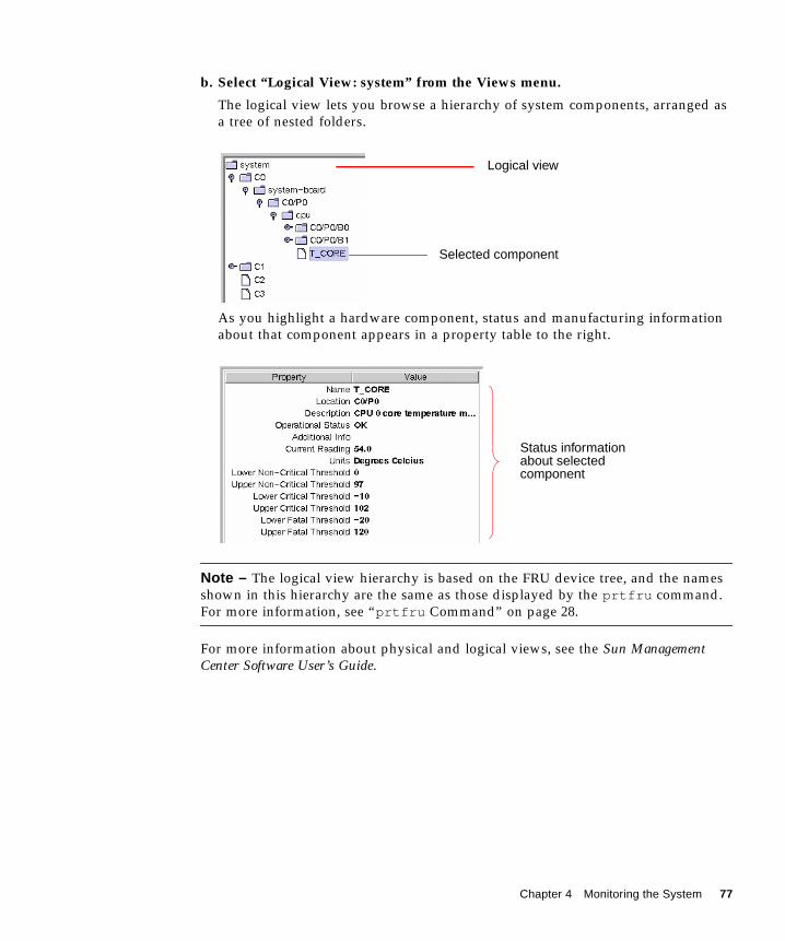
b. Select “Logical View: system” from the Views menu.
The logical view lets you browse a hierarchy of system components, arranged as
a tree of nested folders.
As you highlight a hardware component, status and manufacturing information
about that component appears in a property table to the right.
Note – The logical view hierarchy is based on the FRU device tree, and the names
shown in this hierarchy are the same as those displayed by the prtfru command.
For more information, see “prtfru Command” on page 28.
For more information about physical and logical views, see the Sun ManagementCenter Software User’s Guide.
Logical view
Selected component
Status informationabout selectedcomponent
Chapter 4 Monitoring the System 77
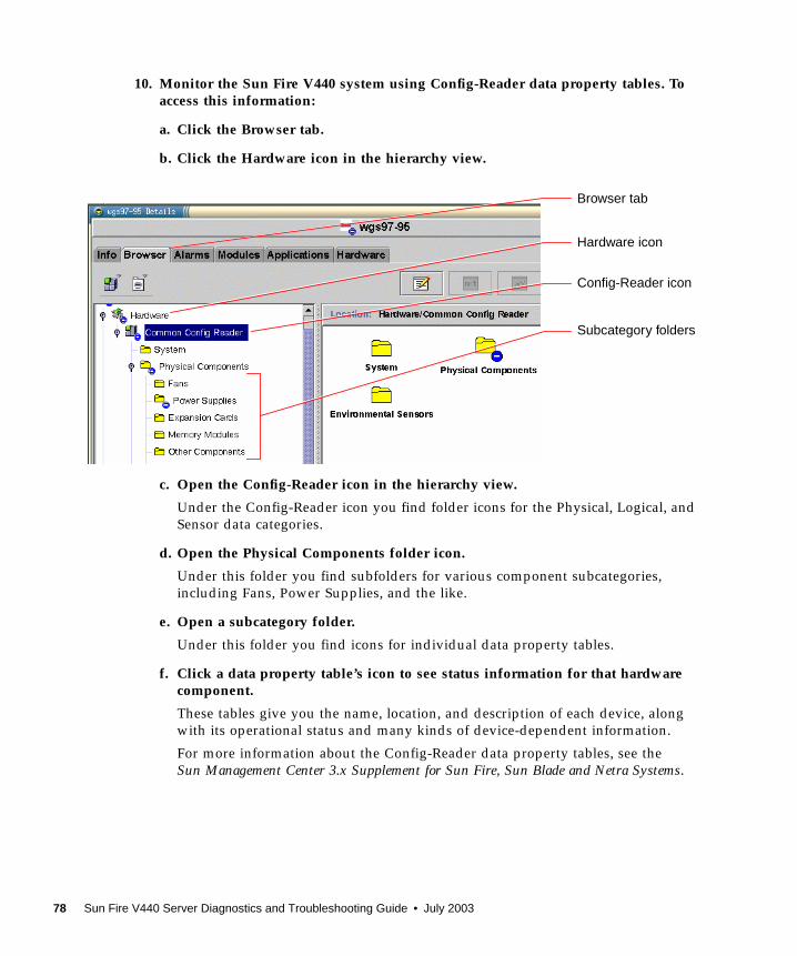
10. Monitor the Sun Fire V440 system using Config-Reader data property tables. Toaccess this information:
a. Click the Browser tab.
b. Click the Hardware icon in the hierarchy view.
c. Open the Config-Reader icon in the hierarchy view.
Under the Config-Reader icon you find folder icons for the Physical, Logical, and
Sensor data categories.
d. Open the Physical Components folder icon.
Under this folder you find subfolders for various component subcategories,
including Fans, Power Supplies, and the like.
e. Open a subcategory folder.
Under this folder you find icons for individual data property tables.
f. Click a data property table’s icon to see status information for that hardwarecomponent.
These tables give you the name, location, and description of each device, along
with its operational status and many kinds of device-dependent information.
For more information about the Config-Reader data property tables, see the
Sun Management Center 3.x Supplement for Sun Fire, Sun Blade and Netra Systems.
Browser tab
Hardware icon
Config-Reader icon
Subcategory folders
78 Sun Fire V440 Server Diagnostics and Troubleshooting Guide • July 2003
What Next
There is much more to Sun Management Center software than what is detailed in
this manual. In particular, you may be interested in setting alarms and administering
security. These topics and many others are covered in the Sun Management CenterSoftware User’s Guide, as well as the other documents accompanying the Sun
Management Center software.
How to Monitor the System UsingSun Advanced Lights Out Manager
This section explains how to use Sun Advanced Lights Out Manager (ALOM) to
monitor a Sun Fire V440 server, and steps you through some of the tool’s most
important features.
For background information about ALOM, see:
■ “Monitoring the System Using Sun Advanced Lights Out Manager” on page 35
■ Sun Advanced Lights Out Manager (ALOM) Online Help.
Before You Begin
Log in to the system console and access the ok prompt. For instructions, see:
■ “How to Get to the ok Prompt” on page 176
There are several ways to connect to and use the ALOM system controller,
depending on how your data center and its network are set up. This procedure
assumes that you intend to monitor the Sun Fire V440 system by way of an
alphanumeric terminal or terminal server connected to the server’s SERIAL MGT
port, or by using a telnet connection to the NET MGT port.
The procedure also assumes that the system console is in its default configuration, so
that you are able to switch between the system controller and the system console.
See:
■ “About Communicating With the System” on page 164
■ “Access Through the Network Management Port” on page 168
Chapter 4 Monitoring the System 79
What to Do
1. If necessary, type the system controller escape sequence.
If you are not already seeing the sc> prompt, type the system controller escape
sequence. By default, this sequence is #. (pound-period).
2. If necessary, log in to ALOM.
If you are not logged in to ALOM, you will be prompted to do so:
Enter the admin account login name and password, or the name and password of a
different login account if one has been set up for you. For the purposes of this
procedure, your account should have full privileges.
Note – The first time you access ALOM, there is no admin account password. You
are instructed to provide one the first time you attempt to execute a privileged
command. Note the password you enter and retain it for future use.
The sc> prompt appears:
This prompt indicates that you now have access to the ALOM system controller
command-line interface.
3. At the sc> prompt, type the showenvironment command.
This command displays a great deal of useful data, starting with temperature
readings from a number of thermal sensors.
ok #.
Please login: adminPlease Enter password: ******
sc>
sc> showenvironment
80 Sun Fire V440 Server Diagnostics and Troubleshooting Guide • July 2003
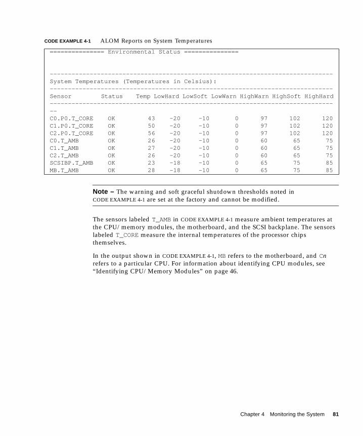
Note – The warning and soft graceful shutdown thresholds noted in
CODE EXAMPLE 4-1 are set at the factory and cannot be modified.
The sensors labeled T_AMBin CODE EXAMPLE 4-1 measure ambient temperatures at
the CPU/memory modules, the motherboard, and the SCSI backplane. The sensors
labeled T_COREmeasure the internal temperatures of the processor chips
themselves.
In the output shown in CODE EXAMPLE 4-1, MBrefers to the motherboard, and Cnrefers to a particular CPU. For information about identifying CPU modules, see
“Identifying CPU/Memory Modules” on page 46.
CODE EXAMPLE 4-1 ALOM Reports on System Temperatures
=============== Environmental Status ===============
------------------------------------------------------------------------------System Temperatures (Temperatures in Celsius):------------------------------------------------------------------------------Sensor Status Temp LowHard LowSoft LowWarn HighWarn HighSoft HighHard--------------------------------------------------------------------------------C0.P0.T_CORE OK 43 -20 -10 0 97 102 120C1.P0.T_CORE OK 50 -20 -10 0 97 102 120C2.P0.T_CORE OK 56 -20 -10 0 97 102 120C0.T_AMB OK 26 -20 -10 0 60 65 75C1.T_AMB OK 27 -20 -10 0 60 65 75C2.T_AMB OK 26 -20 -10 0 60 65 75SCSIBP.T_AMB OK 23 -18 -10 0 65 75 85MB.T_AMB OK 28 -18 -10 0 65 75 85
Chapter 4 Monitoring the System 81

The showenvironment command also gives the position of the system control
keyswitch and the condition of the three LEDs on the front panel.
The showenvironment command reports the status of system disks and fans.
CODE EXAMPLE 4-2 ALOM Reports on Keyswitch Position and System Status LEDs
--------------------------------------
Front Status Panel:
--------------------------------------
Keyswitch position: NORMAL
---------------------------------------------------
System Indicator Status:
---------------------------------------------------
SYS_FRONT.LOCATE SYS_FRONT.SERVICE SYS_FRONT.ACT
--------------------------------------------------------
OFF OFF OFF
CODE EXAMPLE 4-3 ALOM Reports on System Disks and Fans
--------------------------------------------System Disks:--------------------------------------------Disk Status Service OK-to-Remove--------------------------------------------HDD0 OK OFF OFFHDD1 OK OFF OFFHDD2 OK OFF OFFHDD3 OK OFF OFF
----------------------------------------------------------Fans (Speeds Revolution Per Minute):----------------------------------------------------------Fan Status Speed Low----------------------------------------------------------FT0.F0 OK 3729 750FT0.F1 OK 3688 750F0 OK 3214 750
82 Sun Fire V440 Server Diagnostics and Troubleshooting Guide • July 2003
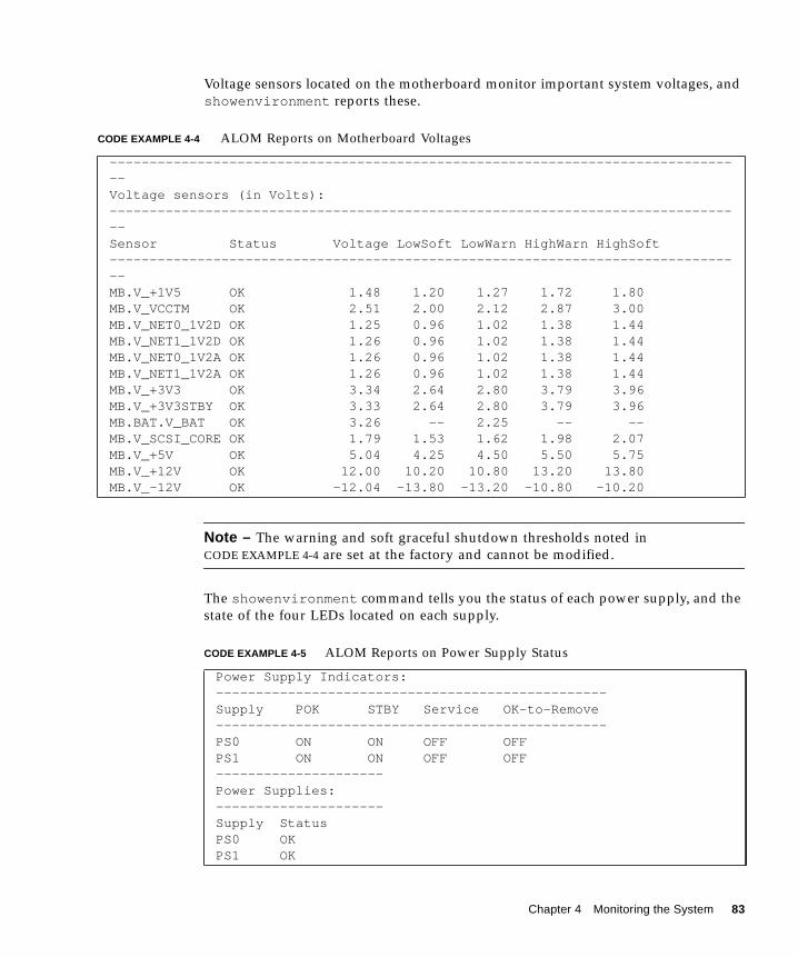
Voltage sensors located on the motherboard monitor important system voltages, and
showenvironment reports these.
Note – The warning and soft graceful shutdown thresholds noted in
CODE EXAMPLE 4-4 are set at the factory and cannot be modified.
The showenvironment command tells you the status of each power supply, and the
state of the four LEDs located on each supply.
CODE EXAMPLE 4-4 ALOM Reports on Motherboard Voltages
--------------------------------------------------------------------------------Voltage sensors (in Volts):--------------------------------------------------------------------------------Sensor Status Voltage LowSoft LowWarn HighWarn HighSoft--------------------------------------------------------------------------------MB.V_+1V5 OK 1.48 1.20 1.27 1.72 1.80MB.V_VCCTM OK 2.51 2.00 2.12 2.87 3.00MB.V_NET0_1V2D OK 1.25 0.96 1.02 1.38 1.44MB.V_NET1_1V2D OK 1.26 0.96 1.02 1.38 1.44MB.V_NET0_1V2A OK 1.26 0.96 1.02 1.38 1.44MB.V_NET1_1V2A OK 1.26 0.96 1.02 1.38 1.44MB.V_+3V3 OK 3.34 2.64 2.80 3.79 3.96MB.V_+3V3STBY OK 3.33 2.64 2.80 3.79 3.96MB.BAT.V_BAT OK 3.26 -- 2.25 -- --MB.V_SCSI_CORE OK 1.79 1.53 1.62 1.98 2.07MB.V_+5V OK 5.04 4.25 4.50 5.50 5.75MB.V_+12V OK 12.00 10.20 10.80 13.20 13.80MB.V_-12V OK -12.04 -13.80 -13.20 -10.80 -10.20
CODE EXAMPLE 4-5 ALOM Reports on Power Supply Status
Power Supply Indicators:-------------------------------------------------Supply POK STBY Service OK-to-Remove-------------------------------------------------PS0 ON ON OFF OFFPS1 ON ON OFF OFF---------------------Power Supplies:---------------------Supply StatusPS0 OKPS1 OK
Chapter 4 Monitoring the System 83
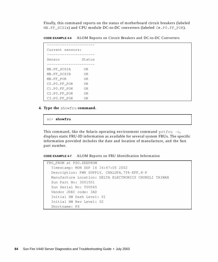
Finally, this command reports on the status of motherboard circuit breakers (labeled
MB.FF_SCSIx) and CPU module DC-to-DC converters (labeled Cn.P0.FF_POK ).
4. Type the showfru command.
This command, like the Solaris operating environment command prtfru -c ,
displays static FRU-ID information as available for several system FRUs. The specific
information provided includes the date and location of manufacture, and the Sun
part number.
CODE EXAMPLE 4-6 ALOM Reports on Circuit Breakers and DC-to-DC Converters
----------------------
Current sensors:
----------------------
Sensor Status
----------------------
MB.FF_SCSIA OK
MB.FF_SCSIB OK
MB.FF_POK OK
C0.P0.FF_POK OK
C1.P0.FF_POK OK
C2.P0.FF_POK OK
C3.P0.FF_POK OK
sc> showfru
CODE EXAMPLE 4-7 ALOM Reports on FRU Identification Information
FRU_PROM at PSO.SEEPROM
Timestamp: MON SEP 16 16:47:05 2002
Description: PWR SUPPLY, CHALUPA,75%-EFF,H-P
Manufacture Location: DELTA ELECTRONICS CHUNGLI TAIWAN
Sun Part No: 3001501
Sun Serial No: T00065
Vendor JDEC code: 3AD
Initial HW Dash Level: 01
Initial HW Rev Level: 02
Shortname: PS
84 Sun Fire V440 Server Diagnostics and Troubleshooting Guide • July 2003
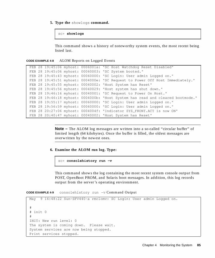
5. Type the showlogs command.
This command shows a history of noteworthy system events, the most recent being
listed last.
Note – The ALOM log messages are written into a so-called “circular buffer” of
limited length (64 kilobytes). Once the buffer is filled, the oldest messages are
overwritten by the newest ones.
6. Examine the ALOM run log. Type:
This command shows the log containing the most recent system console output from
POST, OpenBoot PROM, and Solaris boot messages. In addition, this log records
output from the server’s operating environment.
sc> showlogs
CODE EXAMPLE 4-8 ALOM Reports on Logged Events
FEB 28 19:45:06 myhost: 0006001a: "SC Host Watchdog Reset Disabled"FEB 28 19:45:06 myhost: 00060003: "SC System booted."FEB 28 19:45:43 myhost: 00060000: "SC Login: User admin Logged on."FEB 28 19:45:51 myhost: 0004000e: "SC Request to Power Off Host Immediately."FEB 28 19:45:55 myhost: 00040002: "Host System has Reset"FEB 28 19:45:56 myhost: 00040029: "Host system has shut down."FEB 28 19:46:16 myhost: 00040001: "SC Request to Power On Host."FEB 28 19:46:18 myhost: 0004000b: "Host System has read and cleared bootmode."FEB 28 19:55:17 myhost: 00060000: "SC Login: User admin Logged on."FEB 28 19:56:59 myhost: 00060000: "SC Login: User admin Logged on."FEB 28 20:27:06 myhost: 0004004f: "Indicator SYS_FRONT.ACT is now ON"FEB 28 20:40:47 myhost: 00040002: "Host System has Reset"
sc> consolehistory run -v
CODE EXAMPLE 4-9 consolehistory run -v Command Output
May 9 14:48:22 Sun-SFV440-a rmclomv: SC Login: User admin Logged on.
## init 0#INIT: New run level: 0The system is coming down. Please wait.System services are now being stopped.Print services stopped.
Chapter 4 Monitoring the System 85

May 9 14:49:18 Sun-SFV440-a last message repeated 1 time
May 9 14:49:38 Sun-SFV440-a syslogd: going down on signal 15
The system is down.syncing file systems... doneProgram terminated{1} ok boot disk
Sun Fire V440, No KeyboardCopyright 1998-2003 Sun Microsystems, Inc. All rights reserved.OpenBoot 4.10.3, 4096 MB memory installed, Serial #53005571.Ethernet address 0:3:ba:28:cd:3, Host ID: 8328cd03.
Initializing 1MB of memory at addr 123fecc000 -
Initializing 1MB of memory at addr 123fe02000 -
Initializing 14MB of memory at addr 123f002000 -
Initializing 16MB of memory at addr 123e002000 -
Initializing 992MB of memory at addr 1200000000 -
Initializing 1024MB of memory at addr 1000000000 -
Initializing 1024MB of memory at addr 200000000 -
Initializing 1024MB of memory at addr 0 -
Rebooting with command: boot diskBoot device: /pci@1f,700000/scsi@2/disk@0,0 File and args:\SunOS Release 5.8 Version Generic_114696-04 64-bitCopyright 1983-2003 Sun Microsystems, Inc. All rights reserved.Hardware watchdog enabledIndicator SYS_FRONT.ACT is now ONconfiguring IPv4 interfaces: ce0.Hostname: Sun-SFV440-aThe system is coming up. Please wait.NIS domainname is Ecd.East.Sun.COMStarting IPv4 router discovery.starting rpc services: rpcbind keyserv ypbind done.Setting netmask of lo0 to 255.0.0.0Setting netmask of ce0 to 255.255.255.0Setting default IPv4 interface for multicast: add net 224.0/4: gateway Sun-SFV440-a
CODE EXAMPLE 4-9 consolehistory run -v Command Output (Continued)
86 Sun Fire V440 Server Diagnostics and Troubleshooting Guide • July 2003
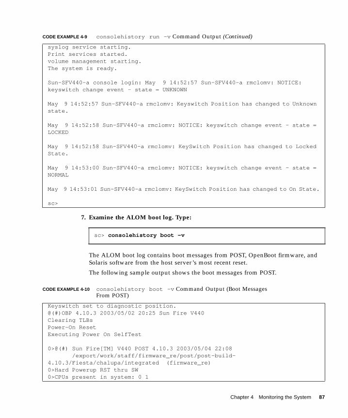
7. Examine the ALOM boot log. Type:
The ALOM boot log contains boot messages from POST, OpenBoot firmware, and
Solaris software from the host server’s most recent reset.
The following sample output shows the boot messages from POST.
syslog service starting.Print services started.volume management starting.The system is ready.
Sun-SFV440-a console login: May 9 14:52:57 Sun-SFV440-a rmclomv: NOTICE:keyswitch change event - state = UNKNOWN
May 9 14:52:57 Sun-SFV440-a rmclomv: Keyswitch Position has changed to Unknownstate.
May 9 14:52:58 Sun-SFV440-a rmclomv: NOTICE: keyswitch change event - state =LOCKED
May 9 14:52:58 Sun-SFV440-a rmclomv: KeySwitch Position has changed to LockedState.
May 9 14:53:00 Sun-SFV440-a rmclomv: NOTICE: keyswitch change event - state =NORMAL
May 9 14:53:01 Sun-SFV440-a rmclomv: KeySwitch Position has changed to On State.
sc>
sc> consolehistory boot -v
CODE EXAMPLE 4-10 consolehistory boot -v Command Output (Boot MessagesFrom POST)
Keyswitch set to diagnostic position.@(#)OBP 4.10.3 2003/05/02 20:25 Sun Fire V440Clearing TLBsPower-On ResetExecuting Power On SelfTest
0>@(#) Sun Fire[TM] V440 POST 4.10.3 2003/05/04 22:08 /export/work/staff/firmware_re/post/post-build-4.10.3/Fiesta/chalupa/integrated (firmware_re)0>Hard Powerup RST thru SW0>CPUs present in system: 0 1
CODE EXAMPLE 4-9 consolehistory run -v Command Output (Continued)
Chapter 4 Monitoring the System 87
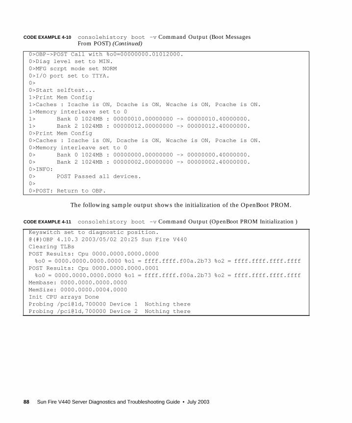
The following sample output shows the initialization of the OpenBoot PROM.
0>OBP->POST Call with %o0=00000000.01012000.0>Diag level set to MIN.0>MFG scrpt mode set NORM0>I/O port set to TTYA.0>0>Start selftest...1>Print Mem Config1>Caches : Icache is ON, Dcache is ON, Wcache is ON, Pcache is ON.1>Memory interleave set to 01> Bank 0 1024MB : 00000010.00000000 -> 00000010.40000000.1> Bank 2 1024MB : 00000012.00000000 -> 00000012.40000000.0>Print Mem Config0>Caches : Icache is ON, Dcache is ON, Wcache is ON, Pcache is ON.0>Memory interleave set to 00> Bank 0 1024MB : 00000000.00000000 -> 00000000.40000000.0> Bank 2 1024MB : 00000002.00000000 -> 00000002.40000000.0>INFO:0> POST Passed all devices.0>0>POST: Return to OBP.
CODE EXAMPLE 4-11 consolehistory boot -v Command Output (OpenBoot PROM Initialization )
Keyswitch set to diagnostic position.@(#)OBP 4.10.3 2003/05/02 20:25 Sun Fire V440Clearing TLBsPOST Results: Cpu 0000.0000.0000.0000
%o0 = 0000.0000.0000.0000 %o1 = ffff.ffff.f00a.2b73 %o2 = ffff.ffff.ffff.ffffPOST Results: Cpu 0000.0000.0000.0001
%o0 = 0000.0000.0000.0000 %o1 = ffff.ffff.f00a.2b73 %o2 = ffff.ffff.ffff.ffffMembase: 0000.0000.0000.0000MemSize: 0000.0000.0004.0000Init CPU arrays DoneProbing /pci@1d,700000 Device 1 Nothing thereProbing /pci@1d,700000 Device 2 Nothing there
CODE EXAMPLE 4-10 consolehistory boot -v Command Output (Boot MessagesFrom POST) (Continued)
88 Sun Fire V440 Server Diagnostics and Troubleshooting Guide • July 2003

The following sample output shows the system banner.
The following sample output shows OpenBoot Diagnostics testing.
The following sample output shows memory initialization by the OpenBoot PROM.
CODE EXAMPLE 4-12 consolehistory boot -v Command Output (System Banner Display)
Sun Fire V440, No KeyboardCopyright 1998-2003 Sun Microsystems, Inc. All rights reserved.OpenBoot 4.10.3, 4096 MB memory installed, Serial #53005571.Ethernet address 0:3:ba:28:cd:3, Host ID: 8328cd03.
CODE EXAMPLE 4-13 consolehistory boot -v Command Output (OpenBoot Diagnostics Testing)
Running diagnostic script obdiag/normal
Testing /pci@1f,700000/network@1Testing /pci@1e,600000/ide@dTesting /pci@1e,600000/isa@7/flashprom@2,0Testing /pci@1e,600000/isa@7/serial@0,2e8Testing /pci@1e,600000/isa@7/serial@0,3f8Testing /pci@1e,600000/isa@7/rtc@0,70Testing /pci@1e,600000/isa@7/i2c@0,320:tests={[email protected],[email protected],[email protected],[email protected]}Testing /pci@1e,600000/isa@7/i2c@0,320:tests={[email protected]}Testing /pci@1e,600000/isa@7/i2c@0,320:tests={[email protected]}Testing /pci@1c,600000/network@2Testing /pci@1f,700000/scsi@2,1Testing /pci@1f,700000/scsi@2
CODE EXAMPLE 4-14 consolehistory boot -v Command Output (Memory Initialization)
Initializing 1MB of memory at addr 123fe02000 -
Initializing 12MB of memory at addr 123f000000 -
Initializing 1008MB of memory at addr 1200000000 -
Initializing 1024MB of memory at addr 1000000000 -
Initializing 1024MB of memory at addr 200000000 -
Initializing 1024MB of memory at addr 0 -
{1} ok boot disk
Chapter 4 Monitoring the System 89
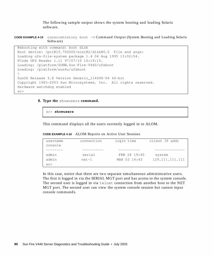
The following sample output shows the system booting and loading Solaris
software.
8. Type the showusers command.
This command displays all the users currently logged in to ALOM.
In this case, notice that there are two separate simultaneous administrative users.
The first is logged in via the SERIAL MGT port and has access to the system console.
The second user is logged in via telnet connection from another host to the NET
MGT port. The second user can view the system console session but cannot input
console commands.
CODE EXAMPLE 4-15 consolehistory boot -v Command Output (System Booting and Loading SolarisSoftware)
Rebooting with command: boot diskBoot device: /pci@1f,700000/scsi@2/disk@0,0 File and args:Loading ufs-file-system package 1.4 04 Aug 1995 13:02:54.FCode UFS Reader 1.11 97/07/10 16:19:15.Loading: /platform/SUNW,Sun-Fire-V440/ufsbootLoading: /platform/sun4u/ufsboot\SunOS Release 5.8 Version Generic_114696-04 64-bitCopyright 1983-2003 Sun Microsystems, Inc. All rights reserved.Hardware watchdog enabledsc>
sc> showusers
CODE EXAMPLE 4-16 ALOM Reports on Active User Sessions
username connection login time client IP addrconsole
-------- ---------- ---------- --------------
admin serial FEB 28 19:45 system
admin net-1 MAR 03 14:43 129.111.111.111
sc>
90 Sun Fire V440 Server Diagnostics and Troubleshooting Guide • July 2003
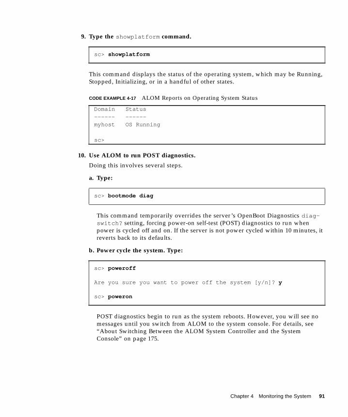
9. Type the showplatform command.
This command displays the status of the operating system, which may be Running,
Stopped, Initializing, or in a handful of other states.
10. Use ALOM to run POST diagnostics.
Doing this involves several steps.
a. Type:
This command temporarily overrides the server’s OpenBoot Diagnostics diag-switch? setting, forcing power-on self-test (POST) diagnostics to run when
power is cycled off and on. If the server is not power cycled within 10 minutes, it
reverts back to its defaults.
b. Power cycle the system. Type:
POST diagnostics begin to run as the system reboots. However, you will see no
messages until you switch from ALOM to the system console. For details, see
“About Switching Between the ALOM System Controller and the System
Console” on page 175.
sc> showplatform
CODE EXAMPLE 4-17 ALOM Reports on Operating System Status
Domain Status
------ ------
myhost OS Running
sc>
sc> bootmode diag
sc> poweroff
Are you sure you want to power off the system [y/n]? y
sc> poweron
Chapter 4 Monitoring the System 91
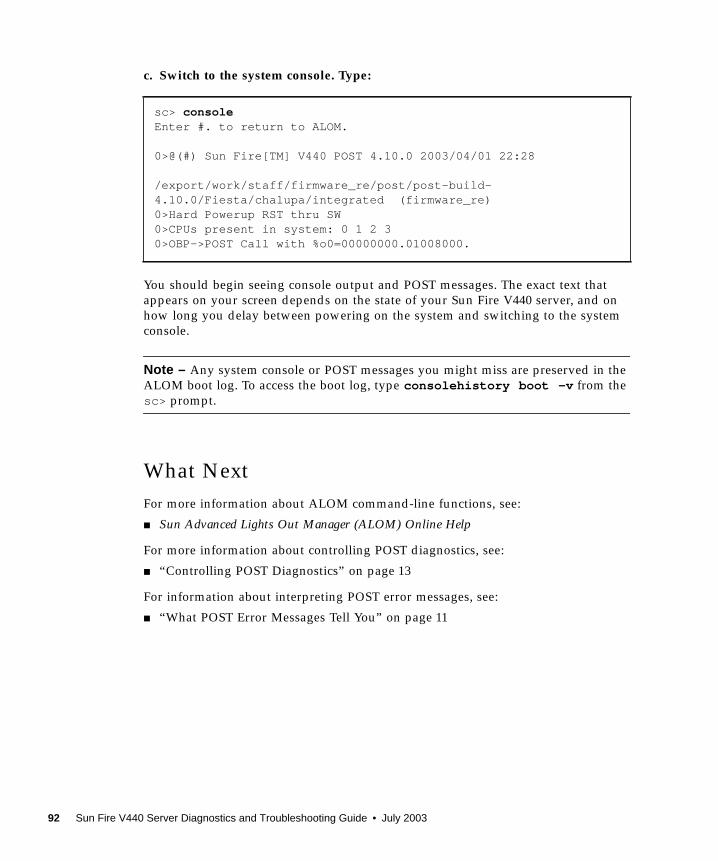
c. Switch to the system console. Type:
You should begin seeing console output and POST messages. The exact text that
appears on your screen depends on the state of your Sun Fire V440 server, and on
how long you delay between powering on the system and switching to the system
console.
Note – Any system console or POST messages you might miss are preserved in the
ALOM boot log. To access the boot log, type consolehistory boot -v from the
sc> prompt.
What Next
For more information about ALOM command-line functions, see:
■ Sun Advanced Lights Out Manager (ALOM) Online Help
For more information about controlling POST diagnostics, see:
■ “Controlling POST Diagnostics” on page 13
For information about interpreting POST error messages, see:
■ “What POST Error Messages Tell You” on page 11
sc> consoleEnter #. to return to ALOM.
0>@(#) Sun Fire[TM] V440 POST 4.10.0 2003/04/01 22:28
/export/work/staff/firmware_re/post/post-build-4.10.0/Fiesta/chalupa/integrated (firmware_re)0>Hard Powerup RST thru SW0>CPUs present in system: 0 1 2 30>OBP->POST Call with %o0=00000000.01008000.
92 Sun Fire V440 Server Diagnostics and Troubleshooting Guide • July 2003
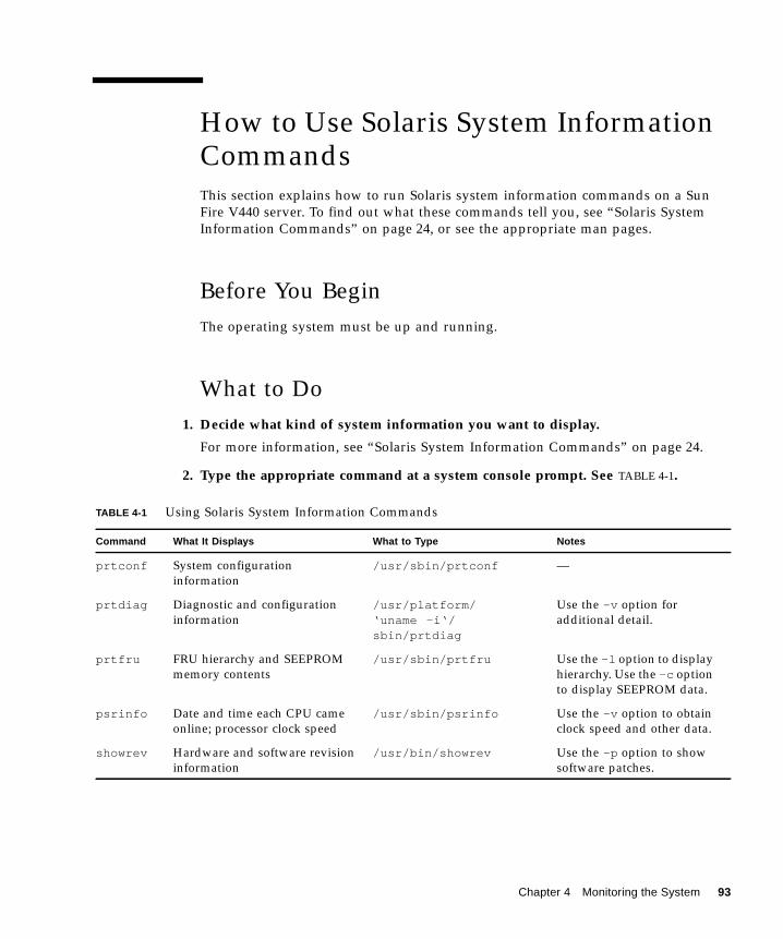
How to Use Solaris System InformationCommands
This section explains how to run Solaris system information commands on a Sun
Fire V440 server. To find out what these commands tell you, see “Solaris System
Information Commands” on page 24, or see the appropriate man pages.
Before You Begin
The operating system must be up and running.
What to Do
1. Decide what kind of system information you want to display.
For more information, see “Solaris System Information Commands” on page 24.
2. Type the appropriate command at a system console prompt. See TABLE 4-1.
TABLE 4-1 Using Solaris System Information Commands
Command What It Displays What to Type Notes
prtconf System configuration
information
/usr/sbin/prtconf —
prtdiag Diagnostic and configuration
information
/usr/platform/‘uname -i‘/sbin/prtdiag
Use the -v option for
additional detail.
prtfru FRU hierarchy and SEEPROM
memory contents
/usr/sbin/prtfru Use the -l option to display
hierarchy. Use the -c option
to display SEEPROM data.
psrinfo Date and time each CPU came
online; processor clock speed
/usr/sbin/psrinfo Use the -v option to obtain
clock speed and other data.
showrev Hardware and software revision
information
/usr/bin/showrev Use the -p option to show
software patches.
Chapter 4 Monitoring the System 93
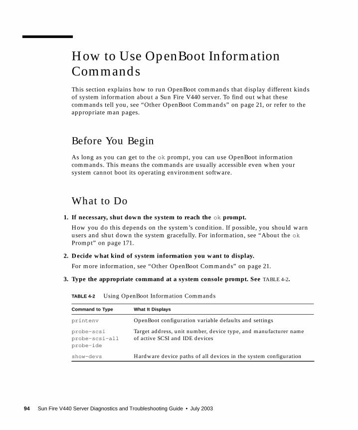
How to Use OpenBoot InformationCommands
This section explains how to run OpenBoot commands that display different kinds
of system information about a Sun Fire V440 server. To find out what these
commands tell you, see “Other OpenBoot Commands” on page 21, or refer to the
appropriate man pages.
Before You Begin
As long as you can get to the ok prompt, you can use OpenBoot information
commands. This means the commands are usually accessible even when your
system cannot boot its operating environment software.
What to Do
1. If necessary, shut down the system to reach the ok prompt.
How you do this depends on the system’s condition. If possible, you should warn
users and shut down the system gracefully. For information, see “About the okPrompt” on page 171.
2. Decide what kind of system information you want to display.
For more information, see “Other OpenBoot Commands” on page 21.
3. Type the appropriate command at a system console prompt. See TABLE 4-2.
TABLE 4-2 Using OpenBoot Information Commands
Command to Type What It Displays
printenv OpenBoot configuration variable defaults and settings
probe-scsiprobe-scsi-allprobe-ide
Target address, unit number, device type, and manufacturer name
of active SCSI and IDE devices
show-devs Hardware device paths of all devices in the system configuration
94 Sun Fire V440 Server Diagnostics and Troubleshooting Guide • July 2003
CHAPTER 5
Exercising the System
Sometimes a server exhibits a problem that cannot be isolated definitively to a
particular hardware or software component. In such cases, it may be useful to run a
diagnostic tool that stresses the system by continuously running a comprehensive
battery of tests. Sun provides two such tools that you can use with the Sun Fire V440
server:
■ SunVTS software
■ Hardware Diagnostic Suite
Hardware Diagnostic Suite is a product you can purchase as an enhancement to Sun
Management Center software. Instructions for using the Hardware Diagnostic Suite
can be found in the Sun Management Center Software User’s Guide.
This chapter describes the tasks necessary to use SunVTS software to exercise your
Sun Fire V440 server.
Tasks covered in this chapter include:
■ “How to Exercise the System Using SunVTS Software” on page 96
■ “How to Check Whether SunVTS Software Is Installed” on page 100
If you want background information about the tools and when to use them, turn to
Chapter 1 and Chapter 2.
Note – The procedures in this chapter assume that you are familiar with the
OpenBoot firmware and that you know how to access the ok prompt. For
background information, see “About the ok Prompt” on page 171. For instructions,
see “How to Get to the ok Prompt” on page 176.
95
How to Exercise the System UsingSunVTS Software
Before You Begin
The Solaris operating environment must be running. You also need to make sure that
SunVTS validation test software is installed on your system. See:
■ “How to Check Whether SunVTS Software Is Installed” on page 100
SunVTS software requires that you use one of two security schemes. The security
scheme you choose must be properly configured in order for you to perform this
procedure. For details, see:
■ SunVTS User’s Guide■ “SunVTS Software and Security” on page 42
SunVTS software features both character-based and graphics-based interfaces. This
procedure assumes that you are using the graphical user interface (GUI) on a system
running the Common Desktop Environment (CDE). For more information about the
character-based SunVTS TTY interface, and specifically for instructions on accessing
it by tip or telnet commands, see the SunVTS User’s Guide.
SunVTS software can be run in several modes. This procedure assumes that you are
using the default Functional mode. For a synopsis of the modes, see:
■ “Exercising the System Using SunVTS Software” on page 40
This procedure also assumes that the Sun Fire V440 server is “headless”—that is, it is
not equipped with a monitor capable of displaying bitmapped graphics. In this case,
you access the SunVTS GUI by logging in remotely from a machine that has a
graphics display.
Finally, this procedure describes how to run SunVTS tests in general. Individual tests
may presume the presence of specific hardware, or may require specific drivers,
cables, or loopback connectors. For information about test options and prerequisites,
see:
■ SunVTS Test Reference Manual■ SunVTS Documentation Supplement
96 Sun Fire V440 Server Diagnostics and Troubleshooting Guide • July 2003
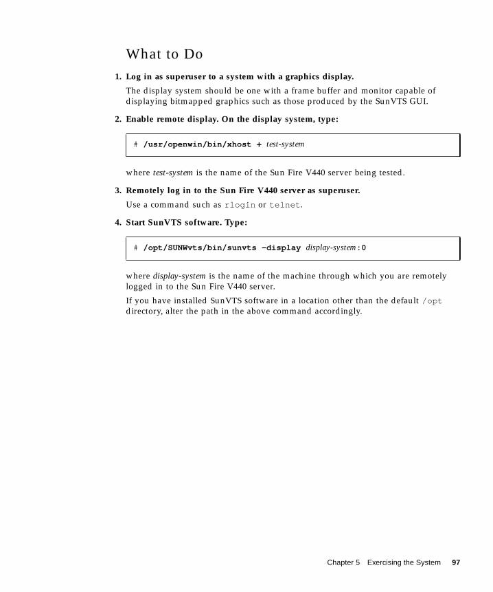
What to Do
1. Log in as superuser to a system with a graphics display.
The display system should be one with a frame buffer and monitor capable of
displaying bitmapped graphics such as those produced by the SunVTS GUI.
2. Enable remote display. On the display system, type:
where test-system is the name of the Sun Fire V440 server being tested.
3. Remotely log in to the Sun Fire V440 server as superuser.
Use a command such as rlogin or telnet .
4. Start SunVTS software. Type:
where display-system is the name of the machine through which you are remotely
logged in to the Sun Fire V440 server.
If you have installed SunVTS software in a location other than the default /optdirectory, alter the path in the above command accordingly.
# /usr/openwin/bin/xhost + test-system
# /opt/SUNWvts/bin/sunvts -display display-system:0
Chapter 5 Exercising the System 97

The SunVTS GUI appears on the display system’s screen.
5. Expand the test lists to see the individual tests.
The interface’s test selection area lists tests in categories, such as “Network,” as
shown below. To expand a category, right-click the icon to the left of the category
name.
Mode selection area
Test messages area
Test selection area
Start and Stop buttons
Log button
+
98 Sun Fire V440 Server Diagnostics and Troubleshooting Guide • July 2003
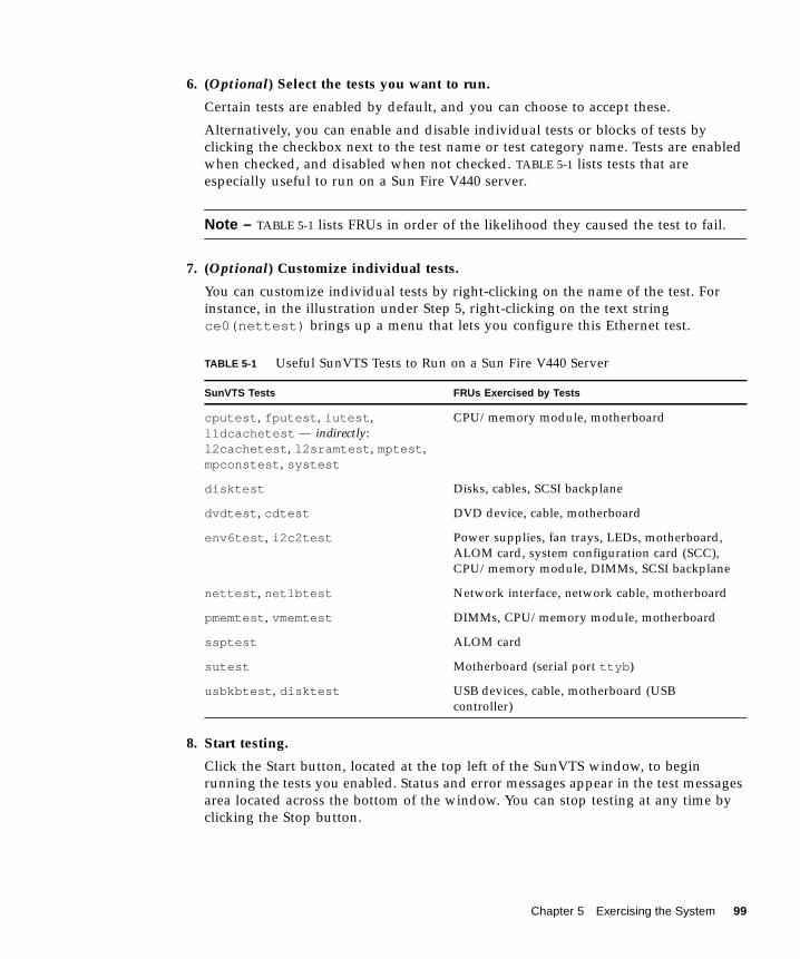
6. (Optional) Select the tests you want to run.
Certain tests are enabled by default, and you can choose to accept these.
Alternatively, you can enable and disable individual tests or blocks of tests by
clicking the checkbox next to the test name or test category name. Tests are enabled
when checked, and disabled when not checked. TABLE 5-1 lists tests that are
especially useful to run on a Sun Fire V440 server.
Note – TABLE 5-1 lists FRUs in order of the likelihood they caused the test to fail.
7. (Optional) Customize individual tests.
You can customize individual tests by right-clicking on the name of the test. For
instance, in the illustration under Step 5, right-clicking on the text string
ce0(nettest) brings up a menu that lets you configure this Ethernet test.
8. Start testing.
Click the Start button, located at the top left of the SunVTS window, to begin
running the tests you enabled. Status and error messages appear in the test messages
area located across the bottom of the window. You can stop testing at any time by
clicking the Stop button.
TABLE 5-1 Useful SunVTS Tests to Run on a Sun Fire V440 Server
SunVTS Tests FRUs Exercised by Tests
cputest , fputest , iutest ,
l1dcachetest — indirectly:
l2cachetest , l2sramtest , mptest ,
mpconstest , systest
CPU/memory module, motherboard
disktest Disks, cables, SCSI backplane
dvdtest , cdtest DVD device, cable, motherboard
env6test , i2c2test Power supplies, fan trays, LEDs, motherboard,
ALOM card, system configuration card (SCC),
CPU/memory module, DIMMs, SCSI backplane
nettest , netlbtest Network interface, network cable, motherboard
pmemtest , vmemtest DIMMs, CPU/memory module, motherboard
ssptest ALOM card
sutest Motherboard (serial port ttyb )
usbkbtest , disktest USB devices, cable, motherboard (USB
controller)
Chapter 5 Exercising the System 99

What Next
During testing, SunVTS software logs all status and error messages. To view these,
click the Log button or select Log Files from the Reports menu. This opens a log
window from which you can choose to view the following logs:
■ Information – Detailed versions of all the status and error messages that appear in
the test messages area.
■ Test Error – Detailed error messages from individual tests.
■ VTS Kernel Error – Error messages pertaining to SunVTS software itself. You
should look here if SunVTS software appears to be acting strangely, especially
when it starts up.
■ UNIX Messages (/var/adm/messages ) – A file containing messages generated
by the operating system and various applications.
■ Log Files (/var/opt/SUNWvts/logs ) – A directory containing the log files.
For further information, see the manuals that accompany SunVTS software. These
are listed in the section “Related Documentation” on page xiv.
How to Check Whether SunVTSSoftware Is Installed
SunVTS software consists of optional packages that may or may not have been
loaded when your system software was installed.
In addition to the SunVTS packages themselves, SunVTS software starting with
version 5.1 requires certain XML and run-time library packages that may not be
installed by default on Solaris 8 software.
Before You Begin
This procedure assumes that the Solaris operating environment is running on the
Sun Fire V440 server, and that you have access to the Solaris command line. For
more information, see:
■ “About Communicating With the System” on page 164
100 Sun Fire V440 Server Diagnostics and Troubleshooting Guide • July 2003
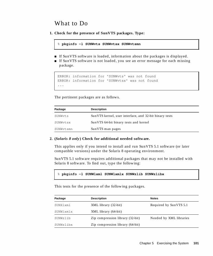
What to Do
1. Check for the presence of SunVTS packages. Type:
■ If SunVTS software is loaded, information about the packages is displayed.
■ If SunVTS software is not loaded, you see an error message for each missing
package.
The pertinent packages are as follows.
2. (Solaris 8 only) Check for additional needed software.
This applies only if you intend to install and run SunVTS 5.1 software (or later
compatible versions) under the Solaris 8 operating environment.
SunVTS 5.1 software requires additional packages that may not be installed with
Solaris 8 software. To find out, type the following:
This tests for the presence of the following packages.
% pkginfo -l SUNWvts SUNWvtsx SUNWvtsmn
ERROR: information for "SUNWvts" was not foundERROR: information for "SUNWvtsx" was not found...
Package Description
SUNWvts SunVTS kernel, user interface, and 32-bit binary tests
SUNWvtsx SunVTS 64-bit binary tests and kernel
SUNWvtsmn SunVTS man pages
% pkginfo -l SUNWlxml SUNWlxmlx SUNWzlib SUNWzlibx
Package Description Notes
SUNXlxml XML library (32-bit) Required by SunVTS 5.1
SUNWlxmlx XML library (64-bit)
SUNWzlib Zip compression library (32-bit) Needed by XML libraries
SUNWzlibx Zip compression library (64-bit)
Chapter 5 Exercising the System 101
3. If necessary, load any missing packages.
Use the pkgadd utility to load onto your system any SunVTS and support packages
that you determined you needed in Step 1 or Step 2.
For the Solaris 8 operating environment, the SunVTS and XML packages are
included on the Software Supplement CD. The zlib packages are included on the
Solaris primary installation CD in the Entire Solaris Software Group.
Note that /opt/SUNWvts is the default directory for installing SunVTS software.
4. Load SunVTS patches, if appropriate.
Patches to SunVTS software are available periodically on the SunSolve OnlineSM Web
site. These patches provide enhancements and bug fixes. In some cases, there are
tests that will not run properly unless the patches are installed.
What Next
For installation information, refer to the SunVTS User’s Guide, the appropriate Solaris
documentation, and the pkgadd man page.
102 Sun Fire V440 Server Diagnostics and Troubleshooting Guide • July 2003
PART II Troubleshooting
The following chapters within this part of the Sun Fire V440 Server Diagnostics andTroubleshooting Guide provide you with approaches for avoiding and troubleshooting
problems that might arise from hardware defects.
For background information about diagnostic tools, as well as detailed instructions
on how to use the tools, see the chapters in Part I – Diagnostics.
Chapters included in Part II are:
■ Chapter 6 – Troubleshooting Options
■ Chapter 7 – Troubleshooting Hardware Problems

CHAPTER 6
Troubleshooting Options
There are several troubleshooting options that you can implement when you set up
and configure the Sun Fire V440 server. By setting up your system with
troubleshooting in mind, you can save time and minimize disruptions if the system
encounters any problems.
Tasks covered in this chapter include:
■ “How to Enable the Core Dump Process” on page 113
■ “How to Test the Core Dump Setup” on page 116
Other information in this chapter includes:
■ “About Updated Troubleshooting Information” on page 105
■ “About Firmware and Software Patch Management” on page 107
■ “About Sun Install Check Tool” on page 107
■ “About Sun Explorer Data Collector” on page 108
■ “About Configuring the System for for Troubleshooting” on page 109
About Updated TroubleshootingInformation
Sun will continue to gather and publish information about the Sun Fire V440 server
long after the initial system documentation is shipped. You can obtain the most
current server troubleshooting information in the Product Notes and at Sun Web
sites. These resources can help you understand and diagnose problems that you
might encounter.
105
Product Notes
Sun Fire V440 Server Product Notes contain late-breaking information about the
system, including the following:
■ Current recommended and required software patches
■ Updated hardware and driver compatibility information
■ Known issues and bug descriptions, including solutions and workarounds
The latest Product Notes are available at:
http://www.sun.com/documentation
Web Sites
SunSolve Online. This site presents a collection of resources for Sun technical and
support information. Access to some of the information on this site depends on the
level of your service contract with Sun. This site includes the following:
■ Patch Support Portal – Everything you need to download and install patches,
including tools, product patches, security patches, signed patches, x86 drivers,
and more.
■ Sun Install Check tool – A utility you can use to verify proper installation and
configuration of a new Sun Fire server. This resource checks a Sun Fire server for
valid patches, hardware, operating environment, and configuration.
■ Sun System Handbook – A document that contains technical information and
provides access to discussion groups for most Sun hardware, including the Sun
Fire V440 server.
■ Support documents, security bulletins, and related links.
The SunSolve Online Web site is at:
http://sunsolve.sun.com
Big Admin. This Web site is a one-stop resource for Sun system administrators. The
Big Admin Web site is at:
http://www.sun.com/bigadmin
106 Sun Fire V440 Server Diagnostics and Troubleshooting Guide • July 2003

About Firmware and Software PatchManagement
Sun makes every attempt to ensure that each system is shipped with the latest
firmware and software. However, in complex systems, bugs and problems are
discovered in the field after systems leave the factory. Often, these problems are
fixed with patches to the system’s firmware. Keeping your system’s firmware and
Solaris operating environment current with the latest recommended and required
patches can help you avoid problems that others might have already discovered and
solved.
Firmware and operating environment updates are often required to diagnose or fix a
problem. Schedule regular updates of your system’s firmware and software so that
you will not have to update the firmware or software at an inconvenient time.
You can find the latest patches and updates for the Sun Fire V440 server at the Web
sites listed in “Web Sites” on page 106.
About Sun Install Check Tool
When you install the SunSM Install Check tool, you also install Sun Explorer Data
Collector. The Sun Install Check tool uses Sun Explorer Data Collector to help you
confirm that Sun Fire V440 server installation has been completed optimally.
Together, they can evaluate your system for the following:
■ Minimum required operating environment level
■ Presence of key critical patches
■ Proper system firmware levels
■ Unsupported hardware components
When Sun Install Check tool and Sun Explorer Data Collector identify potential
problems, a report is generated that provides specific instructions to remedy the
issue.
The Sun Install Check tool is available at:
http://sunsolve.sun.com
At that site, click on the link to the Sun Install Check tool.
See also “About Sun Explorer Data Collector” on page 108.
Chapter 6 Troubleshooting Options 107
About Sun Explorer Data Collector
The Sun Explorer Data Collector is a system data collection tool that Sun support
services engineers sometimes use when troubleshooting Sun SPARC and x86
systems. In certain support situations, Sun support services engineers might ask you
to install and run this tool. If you installed the Sun Install Check tool at initial
installation, you also installed Sun Explorer Data Collector. If you did not install the
Sun Install Check tool, you can install Sun Explorer Data Collector later without the
Sun Install Check tool. By installing this tool as part of your initial system setup, you
avoid having to install the tool at a later, and often inconvenient time.
Both the Sun Install Check tool (with bundled Sun Explorer Data Collector) and the
Sun Explorer Data Collector (standalone) are available at:
http://sunsolve.sun.com
At that site, click on the appropriate link.
About Sun Remote Services Net Connect
Sun Remote Services (SRS) Net Connect is a collection of system management
services designed to help you better control your computing environment. These
Web-delivered services enable you to monitor systems, to create performance and
trend reports, and to receive automatic notification of system events. These services
help you to act more quickly when a system event occurs and to manage potential
issues before they become problems.
More information about SRS Net Connect is available at:
http://www.sun.com/service/support/srs/netconnect
108 Sun Fire V440 Server Diagnostics and Troubleshooting Guide • July 2003
About Configuring the System for forTroubleshooting
System failures are characterized by certain symptoms. Each symptom can be traced
to one or more problems or causes by using specific troubleshooting tools and
techniques. This section describes troubleshooting tools and techniques that you can
control through configuration variables.
Hardware Watchdog Mechanism
The hardware watchdog mechanism is a hardware timer that is continually reset as
long as the operating system is running. If the system hangs, the operating system is
no longer able to reset the timer. The timer then expires and causes an automatic
externally initiated reset (XIR), displaying debug information on the system console.
The hardware watchdog mechanism is enabled by default. If the hardware watchdog
mechanism is disabled, the Solaris operating environment must be configured before
the hardware watchdog mechanism can be reenabled.
The configuration variable error-reset-recovery allows you to control how the
hardware watchdog mechanism behaves when the timer expires. The following are
the error-reset-recovery settings:
■ boot (default) – Resets the timer and attempts to reboot the system
■ sync (recommended) – Attempts to automatically generate a core dump file
dump, reset the timer, and reboot the system
■ none (equivalent to issuing a manual XIR from the ALOM system controller) –
Drops the server to the ok prompt, enabling you to issue commands and debug
the system
For more information about the hardware watchdog mechanism and XIR, see
“Hardware Watchdog Mechanism and XIR” in the Sun Fire V440 ServerAdministration Guide.
For information about troubleshooting system hangs: see:
■ “Responding to System Hang States” on page 123
■ “How to Troubleshoot a System That Is Hanging” on page 160
Chapter 6 Troubleshooting Options 109
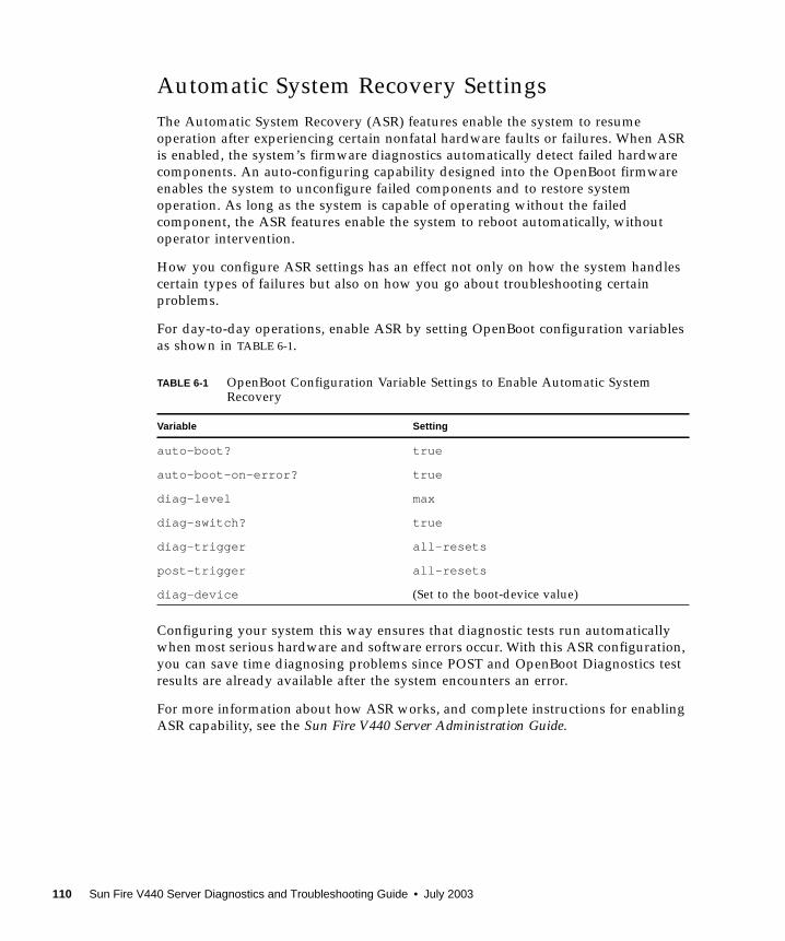
Automatic System Recovery Settings
The Automatic System Recovery (ASR) features enable the system to resume
operation after experiencing certain nonfatal hardware faults or failures. When ASR
is enabled, the system’s firmware diagnostics automatically detect failed hardware
components. An auto-configuring capability designed into the OpenBoot firmware
enables the system to unconfigure failed components and to restore system
operation. As long as the system is capable of operating without the failed
component, the ASR features enable the system to reboot automatically, without
operator intervention.
How you configure ASR settings has an effect not only on how the system handles
certain types of failures but also on how you go about troubleshooting certain
problems.
For day-to-day operations, enable ASR by setting OpenBoot configuration variables
as shown in TABLE 6-1.
Configuring your system this way ensures that diagnostic tests run automatically
when most serious hardware and software errors occur. With this ASR configuration,
you can save time diagnosing problems since POST and OpenBoot Diagnostics test
results are already available after the system encounters an error.
For more information about how ASR works, and complete instructions for enabling
ASR capability, see the Sun Fire V440 Server Administration Guide.
TABLE 6-1 OpenBoot Configuration Variable Settings to Enable Automatic SystemRecovery
Variable Setting
auto-boot? true
auto-boot-on-error? true
diag-level max
diag-switch? true
diag-trigger all-resets
post-trigger all-resets
diag-device (Set to the boot-device value)
110 Sun Fire V440 Server Diagnostics and Troubleshooting Guide • July 2003

Remote Troubleshooting Capabilities
You can use the Sun Advanced Lights Out Manager (ALOM) system controller to
troubleshoot and diagnose the system remotely. The ALOM system controller lets
you do the following:
■ Turn system power on and off
■ Control the Locator LED
■ Change OpenBoot configuration variables
■ View system environmental status information
■ View system event logs
In addition, you can use the ALOM system controller to access the system console,
provided it has not been redirected. System console access enables you to do the
following:
■ Run OpenBoot Diagnostics tests
■ View Solaris operating environment output
■ View POST output
■ Issue firmware commands at the ok prompt
■ View error events when the Solaris operating environment terminates abruptly
For more information about ALOM, see:
■ “Monitoring the System Using Sun Advanced Lights Out Manager” on page 35
■ “How to Monitor the System Using Sun Advanced Lights Out Manager” on
page 79
■ Sun Advanced Lights Out Manager (ALOM) Online Help
For more information about the system console, see Appendix A.
System Console Logging
Console logging is the ability to collect and log system console output. Console
logging captures console messages so that system failure data, like Fatal Reset error
details and POST output, can be recorded and analyzed.
Console logging is especially valuable when troubleshooting Fatal Reset errors and
RED State Exceptions. In these conditions, the Solaris operating environment
terminates abruptly, and although it sends messages to the system console, the
Chapter 6 Troubleshooting Options 111
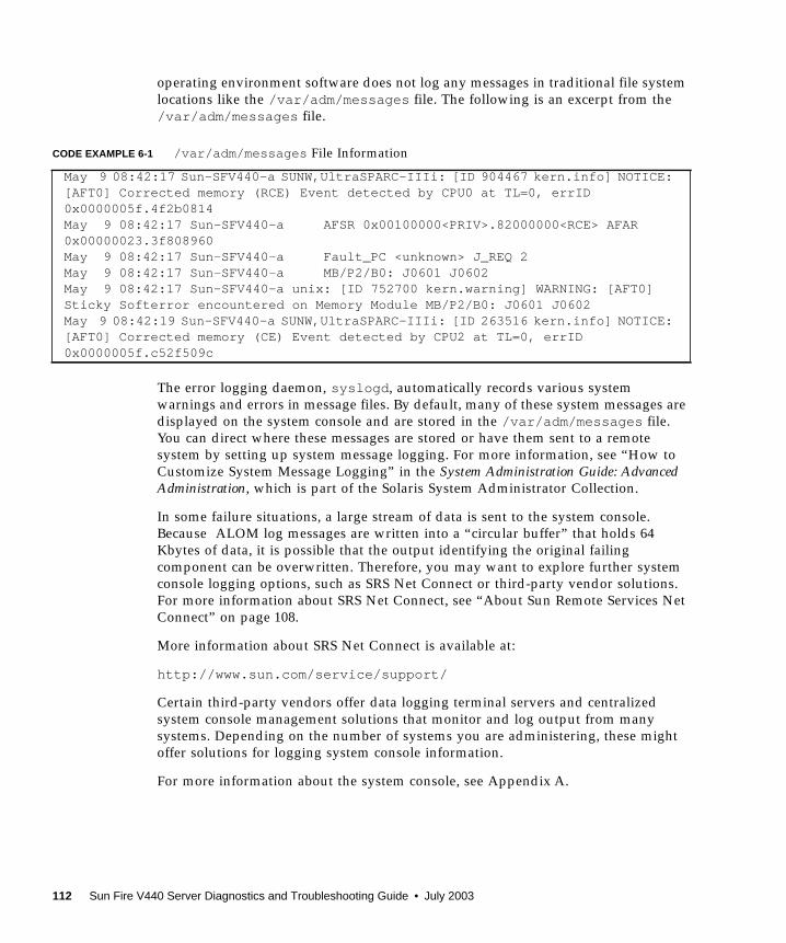
operating environment software does not log any messages in traditional file system
locations like the /var/adm/messages file. The following is an excerpt from the
/var/adm/messages file.
The error logging daemon, syslogd , automatically records various system
warnings and errors in message files. By default, many of these system messages are
displayed on the system console and are stored in the /var/adm/messages file.
You can direct where these messages are stored or have them sent to a remote
system by setting up system message logging. For more information, see “How to
Customize System Message Logging” in the System Administration Guide: AdvancedAdministration, which is part of the Solaris System Administrator Collection.
In some failure situations, a large stream of data is sent to the system console.
Because ALOM log messages are written into a “circular buffer” that holds 64
Kbytes of data, it is possible that the output identifying the original failing
component can be overwritten. Therefore, you may want to explore further system
console logging options, such as SRS Net Connect or third-party vendor solutions.
For more information about SRS Net Connect, see “About Sun Remote Services Net
Connect” on page 108.
More information about SRS Net Connect is available at:
http://www.sun.com/service/support/
Certain third-party vendors offer data logging terminal servers and centralized
system console management solutions that monitor and log output from many
systems. Depending on the number of systems you are administering, these might
offer solutions for logging system console information.
For more information about the system console, see Appendix A.
CODE EXAMPLE 6-1 /var/adm/messages File Information
May 9 08:42:17 Sun-SFV440-a SUNW,UltraSPARC-IIIi: [ID 904467 kern.info] NOTICE:[AFT0] Corrected memory (RCE) Event detected by CPU0 at TL=0, errID0x0000005f.4f2b0814May 9 08:42:17 Sun-SFV440-a AFSR 0x00100000<PRIV>.82000000<RCE> AFAR0x00000023.3f808960May 9 08:42:17 Sun-SFV440-a Fault_PC <unknown> J_REQ 2May 9 08:42:17 Sun-SFV440-a MB/P2/B0: J0601 J0602May 9 08:42:17 Sun-SFV440-a unix: [ID 752700 kern.warning] WARNING: [AFT0]Sticky Softerror encountered on Memory Module MB/P2/B0: J0601 J0602May 9 08:42:19 Sun-SFV440-a SUNW,UltraSPARC-IIIi: [ID 263516 kern.info] NOTICE:[AFT0] Corrected memory (CE) Event detected by CPU2 at TL=0, errID0x0000005f.c52f509c
112 Sun Fire V440 Server Diagnostics and Troubleshooting Guide • July 2003

About the Core Dump Process
In some failure situations, a Sun engineer might need to analyze a system core dump
file to determine the root cause of a system failure. Although the core dump process
is enabled by default, you should configure your system so that the core dump file is
saved in a location with adequate space. You might also want to change the default
core dump directory to another locally mounted location so that you can better
manage any system core dumps. In certain testing and pre-production
environments, this is recommended since core dump files can take up a large
amount of file system space.
Swap space is used to save the dump of system memory. By default, Solaris software
uses the first swap device that is defined. This first swap device is known as the
dump device.
During a system core dump, the system saves the content of kernel core memory to
the dump device. The dump content is compressed during the dump process at a 3:1
ratio; that is, if the system were using 6 Gbytes of kernel memory, the dump file will
be about 2 Gbytes. For a typical system, the dump device should be at least one third
the size of the total system memory.
See “How to Enable the Core Dump Process” on page 113 for instructions on how to
calculate the amount of available swap space.
How to Enable the Core Dump Process
This is normally a task that you would complete just prior to placing a system into
the production environment.
Before You Begin
Access the system console. See:
■ “About Communicating With the System” on page 164
Chapter 6 Troubleshooting Options 113
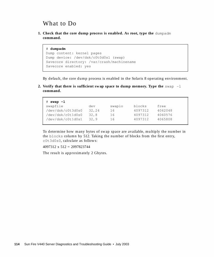
What to Do
1. Check that the core dump process is enabled. As root, type the dumpadmcommand.
By default, the core dump process is enabled in the Solaris 8 operating environment.
2. Verify that there is sufficient swap space to dump memory. Type the swap -lcommand.
To determine how many bytes of swap space are available, multiply the number in
the blocks column by 512. Taking the number of blocks from the first entry,
c0t3d0s0 , calculate as follows:
4097312 x 512 = 2097823744
The result is approximately 2 Gbytes.
# dumpadmDump content: kernel pagesDump device: /dev/dsk/c0t0d0s1 (swap)Savecore directory: /var/crash/machinenameSavecore enabled: yes
# swap -lswapfile dev swaplo blocks free/dev/dsk/c0t3d0s0 32,24 16 4097312 4062048/dev/dsk/c0t1d0s0 32,8 16 4097312 4060576/dev/dsk/c0t1d0s1 32,9 16 4097312 4065808
114 Sun Fire V440 Server Diagnostics and Troubleshooting Guide • July 2003
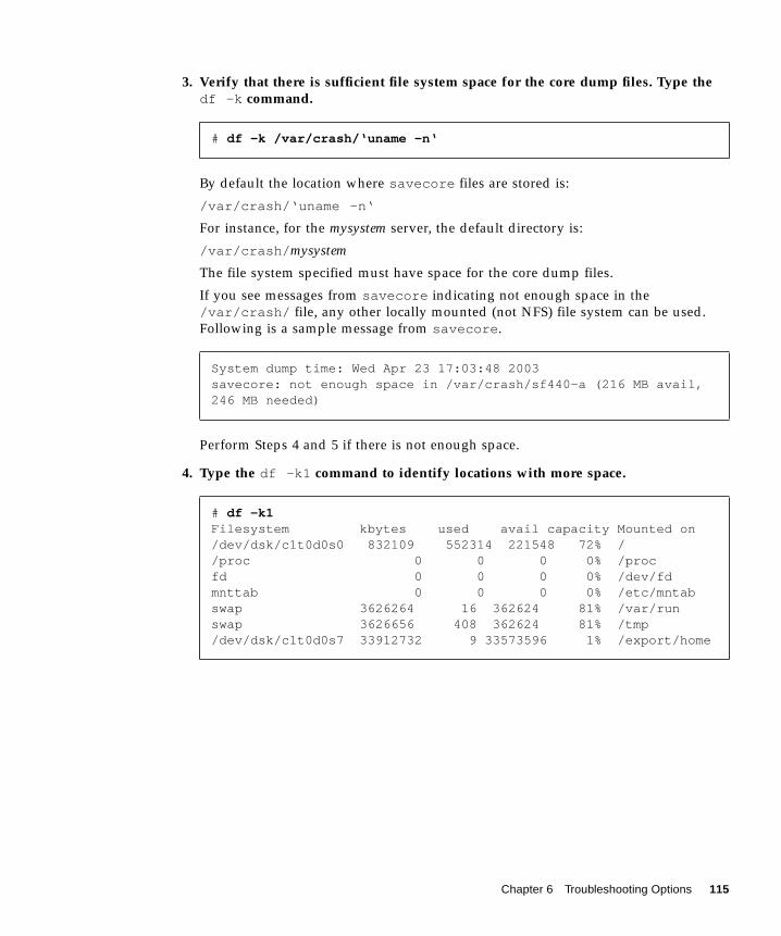
3. Verify that there is sufficient file system space for the core dump files. Type thedf -k command.
By default the location where savecore files are stored is:
/var/crash/‘uname -n‘
For instance, for the mysystem server, the default directory is:
/var/crash/ mysystem
The file system specified must have space for the core dump files.
If you see messages from savecore indicating not enough space in the
/var/crash/ file, any other locally mounted (not NFS) file system can be used.
Following is a sample message from savecore .
Perform Steps 4 and 5 if there is not enough space.
4. Type the df -k1 command to identify locations with more space.
# df -k /var/crash/‘uname -n‘
System dump time: Wed Apr 23 17:03:48 2003savecore: not enough space in /var/crash/sf440-a (216 MB avail,246 MB needed)
# df -k1Filesystem kbytes used avail capacity Mounted on/dev/dsk/c1t0d0s0 832109 552314 221548 72% //proc 0 0 0 0% /procfd 0 0 0 0% /dev/fdmnttab 0 0 0 0% /etc/mntabswap 3626264 16 362624 81% /var/runswap 3626656 408 362624 81% /tmp/dev/dsk/c1t0d0s7 33912732 9 33573596 1% /export/home
Chapter 6 Troubleshooting Options 115
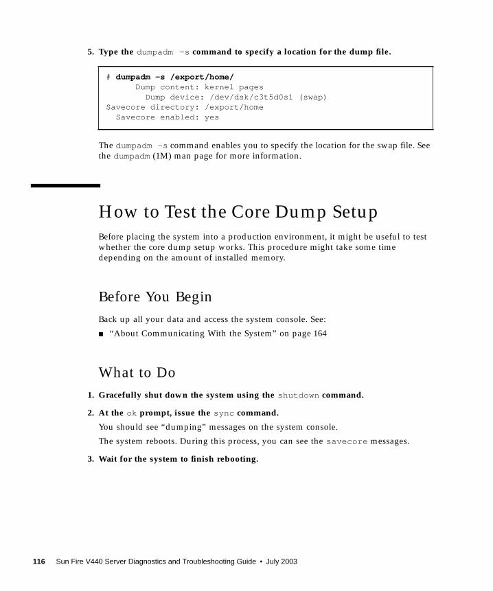
5. Type the dumpadm -s command to specify a location for the dump file.
The dumpadm -s command enables you to specify the location for the swap file. See
the dumpadm(1M) man page for more information.
How to Test the Core Dump Setup
Before placing the system into a production environment, it might be useful to test
whether the core dump setup works. This procedure might take some time
depending on the amount of installed memory.
Before You Begin
Back up all your data and access the system console. See:
■ “About Communicating With the System” on page 164
What to Do
1. Gracefully shut down the system using the shutdown command.
2. At the ok prompt, issue the sync command.
You should see “dumping” messages on the system console.
The system reboots. During this process, you can see the savecore messages.
3. Wait for the system to finish rebooting.
# dumpadm -s /export/home/Dump content: kernel pages
Dump device: /dev/dsk/c3t5d0s1 (swap)Savecore directory: /export/home
Savecore enabled: yes
116 Sun Fire V440 Server Diagnostics and Troubleshooting Guide • July 2003

4. Look for system core dump files in your savecore directory.
The files are named unix. y and vmcore. y, where y is the integer dump number.
There should also be a bounds file that contains the next crash number savecorewill use.
If a core dump is not generated, perform the procedure described in “How to Enable
the Core Dump Process” on page 113.
Chapter 6 Troubleshooting Options 117

118 Sun Fire V440 Server Diagnostics and Troubleshooting Guide • July 2003
CHAPTER 7
Troubleshooting Hardware Problems
The term troubleshooting refers to the act of applying diagnostic tools—often
heuristically and accompanied by common sense—to determine the causes of system
problems.
Each system problem must be treated on its own merits. It is not possible to provide
a cookbook of actions that resolve each problem. However, this chapter provides
some approaches and procedures, which used in combination with experience and
common sense, can resolve many problems that might arise.
Tasks covered in this chapter include:
■ “How to Troubleshoot a System With the Operating System Responding” on
page 126
■ “How to Troubleshoot a System After an Unexpected Reboot” on page 131
■ “How to Troubleshoot Fatal Reset Errors and RED State Exceptions” on page 142
■ “How to Troubleshoot a System That Does Not Boot” on page 154
■ “How to Troubleshoot a System That Is Hanging” on page 160
Other information in this chapter includes:
■ “About the Information to Gather During Troubleshooting” on page 120
■ “About System Error States” on page 123
■ “About Unexpected Reboots” on page 126
119
About the Information to Gather DuringTroubleshooting
Familiarity with a wide variety of equipment, and experience with a particular
machine’s common failure modes can be invaluable when troubleshooting system
problems. Establishing a systematic approach to investigating and solving a
particular system’s problems can help ensure that you can quickly identify and
remedy most issues as they arise.
The Sun Fire V440 server indicates and logs events and errors in a variety of ways.
Depending on the system’s configuration and software, certain types of errors are
captured only temporarily. Therefore, you must observe and record all available
information immediately before you attempt any corrective action. POST, for
instance, accumulates a list of failed components across resets. However, failed
component information is cleared after a system reset. Similarly, the state of LEDs in
a hung system is lost when the system reboots or resets.
If you encounter any system problems that are not familiar to you, gather as much
information as you can before you attempt any remedial actions. The following task
listing outlines a basic approach to information gathering.
■ Gather as much error information (error indications and messages) as you can
from the system. See “Error Information From the ALOM System Controller” on
page 121, “Error Information From Sun Management Center” on page 121, and
“Error Information From the System” on page 121 for more information about
sources of error indications and messages.
■ Gather as much information as you can about the system by reviewing and
verifying the system’s operating environment, firmware, and hardware
configuration. To accurately analyze error indications and messages, you or a Sun
support services engineer must know the system’s operating environment and
patch revision levels as well as the specific hardware configuration. See
“Recording Information About the System” on page 122.
■ Compare the specifics of your situation to the latest published information about
your system. Often, unfamiliar problems you encounter have been seen,
diagnosed, and fixed by others. This information might help you avoid the
unnecessary expense of replacing parts that are not actually failing. See “About
Updated Troubleshooting Information” on page 105 for information sources.
120 Sun Fire V440 Server Diagnostics and Troubleshooting Guide • July 2003
Error Information From the ALOM System
Controller
In most troubleshooting situations, you can use the ALOM system controller as the
primary source of information about the system. On the Sun Fire V440 server, the
ALOM system controller provides you with access to a variety of system logs and
other information about the system, even when the system is powered off. For more
information about ALOM, see:
■ “Monitoring the System Using Sun Advanced Lights Out Manager” on page 35
■ “How to Monitor the System Using Sun Advanced Lights Out Manager” on
page 79
■ Sun Advanced Lights Out Manager (ALOM) Online Help
Error Information From Sun Management Center
If Sun Management Center software is installed and the system and operating
environment are running, Sun Management Center lets you monitor the status of
various components in the system. For more information, see:
■ “Monitoring the System Using Sun Management Center” on page 36
■ “How to Monitor the System Using Sun Management Center” on page 74
Error Information From the System
Depending on the state of the system, you should check as many of the following
sources as possible for error indications and record the information found.
■ Output from the prtdiag -v command – If Solaris software is running, issue the
prtdiag -v command to capture information stored by OpenBoot Diagnostics
and POST tests. Any information from these tests about the current state of the
system is lost when the system is reset. See “How to Troubleshoot a System With
the Operating System Responding” on page 126.
■ Output from show-post-results and show-obdiag-results commands –
From the ok prompt, issue the show-post-results command or show-obdiag-results command to view summaries of the results from the most
recent POST and OpenBoot Diagnostics tests, respectively. The test results are
saved across power cycles and provide an indication of which components passed
and which components failed POST or OpenBoot Diagnostics tests. See “How to
View Diagnostic Test Results After the Fact” on page 70.
Chapter 7 Troubleshooting Hardware Problems 121
■ State of system LEDs – The system LEDs can be viewed in various locations on the
system or by using the ALOM system controller. Be sure to check any network
port LEDs for activity as you examine the system. Any information about the
state of the system from the LEDs is lost when the system is reset. For more
information about using LEDs to troubleshoot system problems, see “How to
Isolate Faults Using LEDs” on page 62.
■ Solaris logs – If Solaris software is running, check the message files in the
/var/adm/messages file. For more information, see “How to Customize System
Message Logging” in the Solaris System Administration Guide: AdvancedAdministration Guide, which is part of the Solaris System Administrator Collection.
■ System console – You can access system console messages from OpenBoot
Diagnostics and POST using the ALOM system controller, provided the system
console has not been redirected. The system controller also provides you access to
boot log information from the latest system reset. For more information about the
system console, see Appendix A.
■ Core files generated from panics – These files are located in the /var/crashdirectory. See “About the Core Dump Process” on page 113 for more information.
Recording Information About the System
As part of your standard operating procedures, it is important to have the following
information about your system readily available:
■ Current patch levels for the system firmware and operating environment
■ Solaris operating environment version
■ Specific hardware configuration information
■ Optional equipment and driver information
■ Recent service records
Having all of this information available and verified makes it easier for you to
recognize any problems already identified by others. This information is also
required if you contact Sun support or your authorized support provider.
It is vital to know the version and patch revision levels of the system’s operating
environment, patch revision levels of the firmware, and your specific hardware
configuration before you attempt to fix any problems. Problems often occur after
changes have been made to the system. Some errors are caused by hardware and
software incompatibilities and interactions. If you have all system information
available, you might be able to quickly fix a problem by simply updating the
system’s firmware. Knowing about recent upgrades or component replacements
might help you avoid replacing components that are not faulty.
122 Sun Fire V440 Server Diagnostics and Troubleshooting Guide • July 2003
About System Error States
When troubleshooting, it is important to understand what kind of error has
occurred, to distinguish between real and apparent system hangs, and to respond
appropriately to error conditions so as to preserve valuable information.
Responding to System Error States
Depending on the severity of a system error, a Sun Fire V440 server might or might
not respond to commands you issue to the system. Once you have gathered all
available information, you can begin taking action. Your actions depend on the
information you have already gathered and the state of the system.
Guidelines to remember:
■ Avoid power cycling the system until you have gathered all the information you
can. Error information might be lost when power cycling the system.
■ If your system appears to be hung, attempt multiple approaches to get the system
to respond. See “Responding to System Hang States” on page 123.
Responding to System Hang States
Troubleshooting a hanging system can be a difficult process because the root cause
of the hang might be masked by false error indications from another part of the
system. Therefore, it is important that you carefully examine all the information
sources available to you before you attempt any remedy. Also, it is helpful to
understand the type of hang the system is experiencing. This hang state information
is especially important to Sun support services engineers, should you contact them.
A system soft hang can be characterized by any of the following symptoms:
■ Usability or performance of the system gradually decreases.
■ New attempts to access the system fail.
■ Some parts of the system appear to stop responding.
■ You can drop the system into the OpenBoot ok prompt level.
Some soft hangs might dissipate on their own, while others will require that the
system be interrupted to gather information at the OpenBoot prompt level. A soft
hang should respond to a break signal that is sent via the system console.
Chapter 7 Troubleshooting Hardware Problems 123
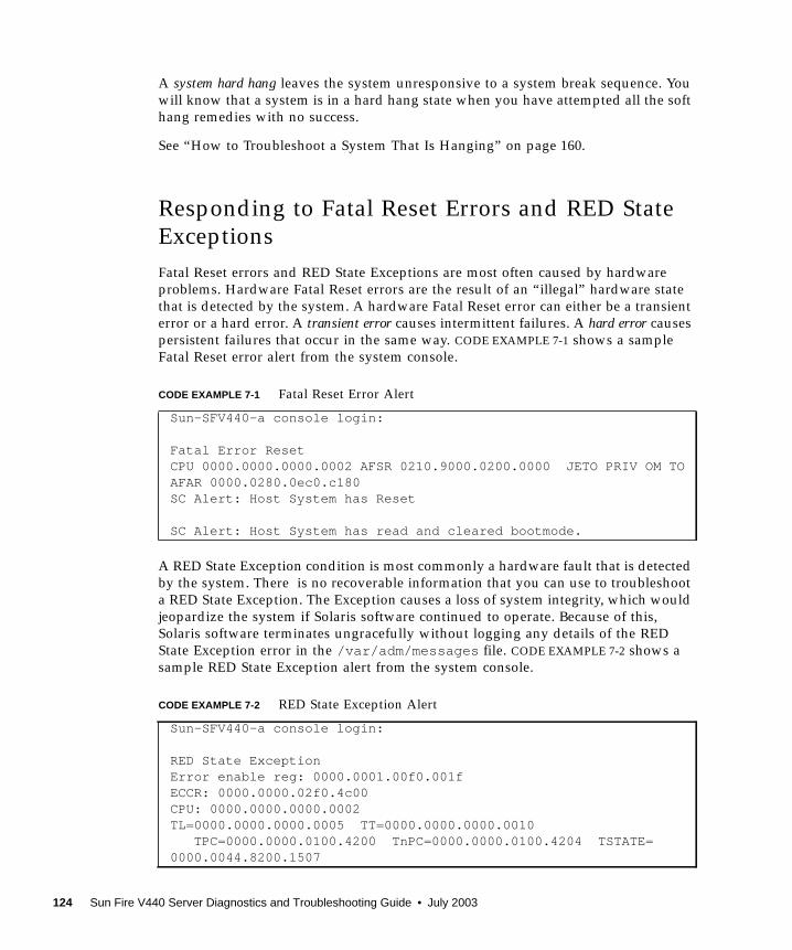
A system hard hang leaves the system unresponsive to a system break sequence. You
will know that a system is in a hard hang state when you have attempted all the soft
hang remedies with no success.
See “How to Troubleshoot a System That Is Hanging” on page 160.
Responding to Fatal Reset Errors and RED State
Exceptions
Fatal Reset errors and RED State Exceptions are most often caused by hardware
problems. Hardware Fatal Reset errors are the result of an “illegal” hardware state
that is detected by the system. A hardware Fatal Reset error can either be a transient
error or a hard error. A transient error causes intermittent failures. A hard error causes
persistent failures that occur in the same way. CODE EXAMPLE 7-1 shows a sample
Fatal Reset error alert from the system console.
A RED State Exception condition is most commonly a hardware fault that is detected
by the system. There is no recoverable information that you can use to troubleshoot
a RED State Exception. The Exception causes a loss of system integrity, which would
jeopardize the system if Solaris software continued to operate. Because of this,
Solaris software terminates ungracefully without logging any details of the RED
State Exception error in the /var/adm/messages file. CODE EXAMPLE 7-2 shows a
sample RED State Exception alert from the system console.
CODE EXAMPLE 7-1 Fatal Reset Error Alert
Sun-SFV440-a console login:
Fatal Error ResetCPU 0000.0000.0000.0002 AFSR 0210.9000.0200.0000 JETO PRIV OM TOAFAR 0000.0280.0ec0.c180SC Alert: Host System has Reset
SC Alert: Host System has read and cleared bootmode.
CODE EXAMPLE 7-2 RED State Exception Alert
Sun-SFV440-a console login:
RED State ExceptionError enable reg: 0000.0001.00f0.001fECCR: 0000.0000.02f0.4c00CPU: 0000.0000.0000.0002TL=0000.0000.0000.0005 TT=0000.0000.0000.0010 TPC=0000.0000.0100.4200 TnPC=0000.0000.0100.4204 TSTATE=0000.0044.8200.1507
124 Sun Fire V440 Server Diagnostics and Troubleshooting Guide • July 2003
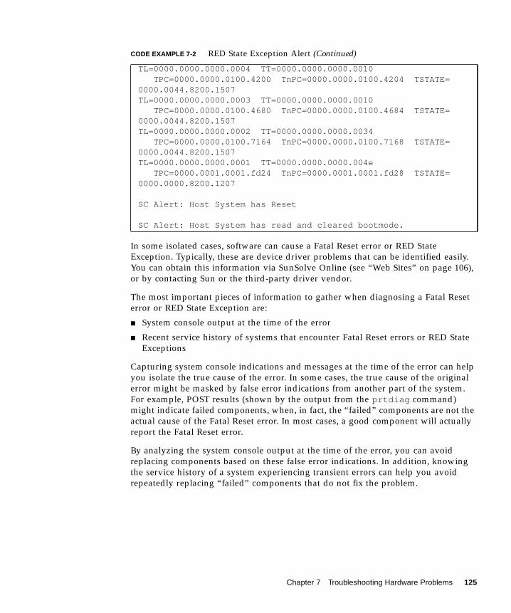
In some isolated cases, software can cause a Fatal Reset error or RED State
Exception. Typically, these are device driver problems that can be identified easily.
You can obtain this information via SunSolve Online (see “Web Sites” on page 106),
or by contacting Sun or the third-party driver vendor.
The most important pieces of information to gather when diagnosing a Fatal Reset
error or RED State Exception are:
■ System console output at the time of the error
■ Recent service history of systems that encounter Fatal Reset errors or RED State
Exceptions
Capturing system console indications and messages at the time of the error can help
you isolate the true cause of the error. In some cases, the true cause of the original
error might be masked by false error indications from another part of the system.
For example, POST results (shown by the output from the prtdiag command)
might indicate failed components, when, in fact, the “failed” components are not the
actual cause of the Fatal Reset error. In most cases, a good component will actually
report the Fatal Reset error.
By analyzing the system console output at the time of the error, you can avoid
replacing components based on these false error indications. In addition, knowing
the service history of a system experiencing transient errors can help you avoid
repeatedly replacing “failed” components that do not fix the problem.
TL=0000.0000.0000.0004 TT=0000.0000.0000.0010 TPC=0000.0000.0100.4200 TnPC=0000.0000.0100.4204 TSTATE=0000.0044.8200.1507TL=0000.0000.0000.0003 TT=0000.0000.0000.0010 TPC=0000.0000.0100.4680 TnPC=0000.0000.0100.4684 TSTATE=0000.0044.8200.1507TL=0000.0000.0000.0002 TT=0000.0000.0000.0034 TPC=0000.0000.0100.7164 TnPC=0000.0000.0100.7168 TSTATE=0000.0044.8200.1507TL=0000.0000.0000.0001 TT=0000.0000.0000.004e TPC=0000.0001.0001.fd24 TnPC=0000.0001.0001.fd28 TSTATE=0000.0000.8200.1207
SC Alert: Host System has Reset
SC Alert: Host System has read and cleared bootmode.
CODE EXAMPLE 7-2 RED State Exception Alert (Continued)
Chapter 7 Troubleshooting Hardware Problems 125

About Unexpected Reboots
Sometimes, a system might reboot unexpectedly. In that case, ensure that the reboot
was not caused by a panic. For example, L2-cache errors, which occur in user space
(not kernel space), might cause Solaris software to log the L2-cache failure data and
reboot the system. The information logged might be sufficient to troubleshoot and
correct the problem. If the reboot was not caused by a panic, it might be caused by a
Fatal Reset error or a RED State Exception. See “How to Troubleshoot Fatal Reset
Errors and RED State Exceptions” on page 142.
Also, system ASR and POST settings can determine the system response to certain
error conditions. If POST is not invoked during the reboot process, or if the system
diagnostics level is not set to max, you might need to run system diagnostics at a
higher level of coverage to determine the source of the reboot if the system message
and system console files do not clearly indicate the source of the reboot.
How to Troubleshoot a System With theOperating System Responding
Before You Begin
Log in to the system controller and access the sc> prompt. For information, see:
■ “About the sc> Prompt” on page 169
This procedure assumes that the system console is in its default configuration, so
that you are able to switch between the system controller and the system console.
See:
■ “About Communicating With the System” on page 164
■ “Access Through the Network Management Port” on page 168
126 Sun Fire V440 Server Diagnostics and Troubleshooting Guide • July 2003
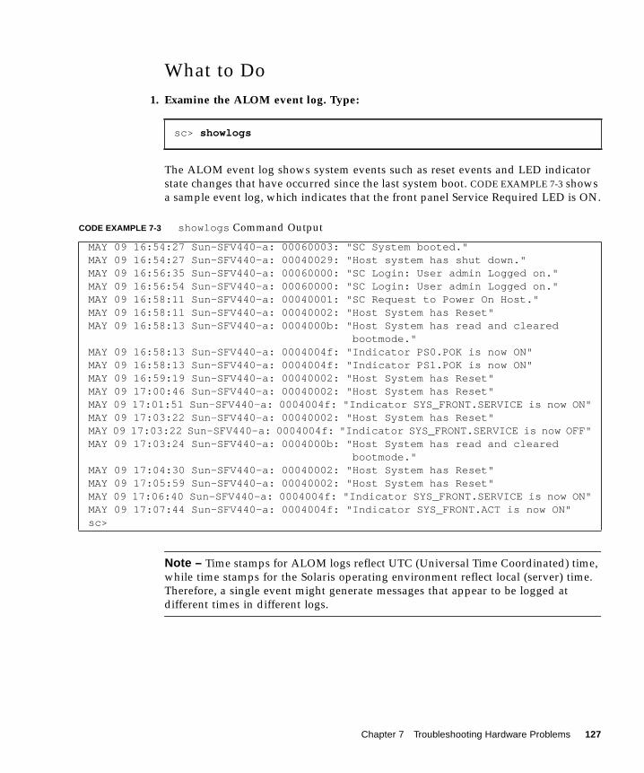
What to Do
1. Examine the ALOM event log. Type:
The ALOM event log shows system events such as reset events and LED indicator
state changes that have occurred since the last system boot. CODE EXAMPLE 7-3 shows
a sample event log, which indicates that the front panel Service Required LED is ON.
Note – Time stamps for ALOM logs reflect UTC (Universal Time Coordinated) time,
while time stamps for the Solaris operating environment reflect local (server) time.
Therefore, a single event might generate messages that appear to be logged at
different times in different logs.
sc> showlogs
CODE EXAMPLE 7-3 showlogs Command Output
MAY 09 16:54:27 Sun-SFV440-a: 00060003: "SC System booted."MAY 09 16:54:27 Sun-SFV440-a: 00040029: "Host system has shut down."MAY 09 16:56:35 Sun-SFV440-a: 00060000: "SC Login: User admin Logged on."MAY 09 16:56:54 Sun-SFV440-a: 00060000: "SC Login: User admin Logged on."MAY 09 16:58:11 Sun-SFV440-a: 00040001: "SC Request to Power On Host."MAY 09 16:58:11 Sun-SFV440-a: 00040002: "Host System has Reset"MAY 09 16:58:13 Sun-SFV440-a: 0004000b: "Host System has read and cleared
bootmode."MAY 09 16:58:13 Sun-SFV440-a: 0004004f: "Indicator PS0.POK is now ON"MAY 09 16:58:13 Sun-SFV440-a: 0004004f: "Indicator PS1.POK is now ON"MAY 09 16:59:19 Sun-SFV440-a: 00040002: "Host System has Reset"MAY 09 17:00:46 Sun-SFV440-a: 00040002: "Host System has Reset"MAY 09 17:01:51 Sun-SFV440-a: 0004004f: "Indicator SYS_FRONT.SERVICE is now ON"MAY 09 17:03:22 Sun-SFV440-a: 00040002: "Host System has Reset"MAY 09 17:03:22 Sun-SFV440-a: 0004004f: "Indicator SYS_FRONT.SERVICE is now OFF"MAY 09 17:03:24 Sun-SFV440-a: 0004000b: "Host System has read and cleared
bootmode."MAY 09 17:04:30 Sun-SFV440-a: 00040002: "Host System has Reset"MAY 09 17:05:59 Sun-SFV440-a: 00040002: "Host System has Reset"MAY 09 17:06:40 Sun-SFV440-a: 0004004f: "Indicator SYS_FRONT.SERVICE is now ON"MAY 09 17:07:44 Sun-SFV440-a: 0004004f: "Indicator SYS_FRONT.ACT is now ON"sc>
Chapter 7 Troubleshooting Hardware Problems 127

2. Examine system environment status. Type:
The showenvironment command reports much useful data such as temperature
readings; state of system and component LEDs; motherboard voltages; and status of
system disks, fans, motherboard circuit breakers, and CPU module DC-to-DC
converters. CODE EXAMPLE 7-4, an excerpt of output from the showenvironmentcommand, indicates that the front panel Service Required LED is ON. When
reviewing the complete output from the showenvironment command, check the
state of all Service Required LEDs and verify that all components show a status of
OK. See CODE EXAMPLE 4-1 for a sample of complete output from the
showenvironment command.
3. Examine the output of the prtdiag -v command. Type:
The prtdiag -v command provides access to information stored by POST and
OpenBoot Diagnostics tests. Any information from this command about the current
state of the system is lost if the system is reset. When examining the output to
identify problems, verify that all installed CPU modules, PCI cards, and memory
modules are listed; check for any Service Required LEDs that are ON; and verify that
the system PROM firmware is the latest version. CODE EXAMPLE 7-5 shows an excerpt
sc> showenvironment
CODE EXAMPLE 7-4 showenvironment Command Output
System Indicator Status:---------------------------------------------------SYS_FRONT.LOCATE SYS_FRONT.SERVICE SYS_FRONT.ACT--------------------------------------------------------OFF ON ON...sc>
sc> consoleEnter #. to return to ALOM.# /usr/platform/‘uname -i‘/sbin/prtdiag -v
128 Sun Fire V440 Server Diagnostics and Troubleshooting Guide • July 2003
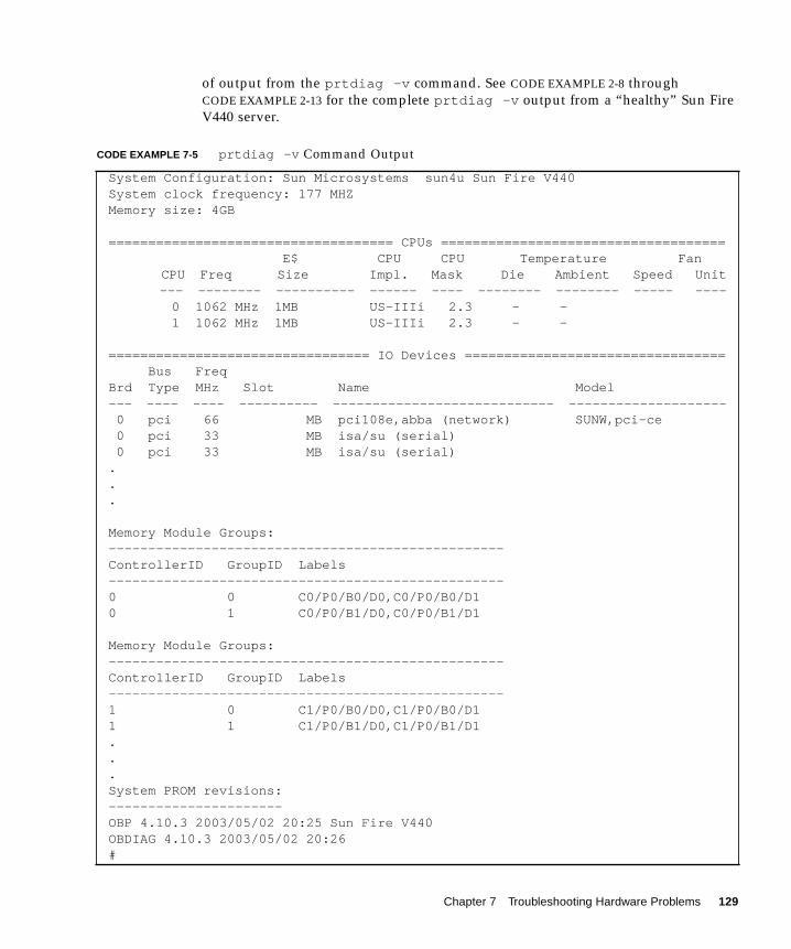
of output from the prtdiag -v command. See CODE EXAMPLE 2-8 through
CODE EXAMPLE 2-13 for the complete prtdiag -v output from a “healthy” Sun Fire
V440 server.
CODE EXAMPLE 7-5 prtdiag -v Command Output
System Configuration: Sun Microsystems sun4u Sun Fire V440System clock frequency: 177 MHZMemory size: 4GB
==================================== CPUs ==================================== E$ CPU CPU Temperature Fan
CPU Freq Size Impl. Mask Die Ambient Speed Unit--- -------- ---------- ------ ---- -------- -------- ----- ----
0 1062 MHz 1MB US-IIIi 2.3 - - 1 1062 MHz 1MB US-IIIi 2.3 - -
================================= IO Devices ================================= Bus FreqBrd Type MHz Slot Name Model--- ---- ---- ---------- ---------------------------- -------------------- 0 pci 66 MB pci108e,abba (network) SUNW,pci-ce 0 pci 33 MB isa/su (serial) 0 pci 33 MB isa/su (serial)...
Memory Module Groups:--------------------------------------------------ControllerID GroupID Labels--------------------------------------------------0 0 C0/P0/B0/D0,C0/P0/B0/D10 1 C0/P0/B1/D0,C0/P0/B1/D1
Memory Module Groups:--------------------------------------------------ControllerID GroupID Labels--------------------------------------------------1 0 C1/P0/B0/D0,C1/P0/B0/D11 1 C1/P0/B1/D0,C1/P0/B1/D1...System PROM revisions:----------------------OBP 4.10.3 2003/05/02 20:25 Sun Fire V440OBDIAG 4.10.3 2003/05/02 20:26#
Chapter 7 Troubleshooting Hardware Problems 129
4. Check the system LEDs.
5. Check the /var/adm/messages file.
The following are clear indications of a failing part:
■ Warning messages from Solaris software about any hardware or software
components
■ ALOM environmental messages about a failing part, including a fan or power
supply
If there is no clear indication of a failing part, investigate the installed applications,
the network, or the disk configuration.
What Next
If you have clear indications that a part has failed or is failing, replace that part as
soon as possible.
If the problem is a confirmed environmental failure, replace the fan or power supply
as soon as possible.
A system with a redundant configuration might still operate in a degraded state, but
the stability and performance of the system will be affected. Since the system is still
operational, attempt to isolate the fault using several methods and tools to ensure
that the part you suspect as faulty really is causing the problems you are
experiencing. See:
■ “About Isolating Faults in the System” on page 32
For information about installing and replacing field-replaceable parts, see:
■ Sun Fire V440 Server Parts Installation and Removal Guide
130 Sun Fire V440 Server Diagnostics and Troubleshooting Guide • July 2003
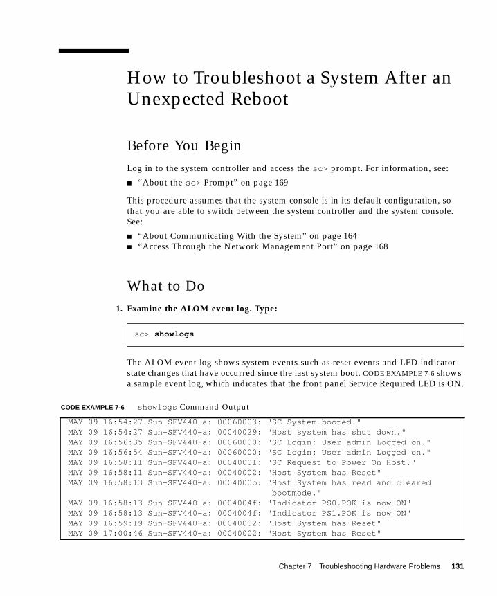
How to Troubleshoot a System After anUnexpected Reboot
Before You Begin
Log in to the system controller and access the sc> prompt. For information, see:
■ “About the sc> Prompt” on page 169
This procedure assumes that the system console is in its default configuration, so
that you are able to switch between the system controller and the system console.
See:
■ “About Communicating With the System” on page 164
■ “Access Through the Network Management Port” on page 168
What to Do
1. Examine the ALOM event log. Type:
The ALOM event log shows system events such as reset events and LED indicator
state changes that have occurred since the last system boot. CODE EXAMPLE 7-6 shows
a sample event log, which indicates that the front panel Service Required LED is ON.
sc> showlogs
CODE EXAMPLE 7-6 showlogs Command Output
MAY 09 16:54:27 Sun-SFV440-a: 00060003: "SC System booted."MAY 09 16:54:27 Sun-SFV440-a: 00040029: "Host system has shut down."MAY 09 16:56:35 Sun-SFV440-a: 00060000: "SC Login: User admin Logged on."MAY 09 16:56:54 Sun-SFV440-a: 00060000: "SC Login: User admin Logged on."MAY 09 16:58:11 Sun-SFV440-a: 00040001: "SC Request to Power On Host."MAY 09 16:58:11 Sun-SFV440-a: 00040002: "Host System has Reset"MAY 09 16:58:13 Sun-SFV440-a: 0004000b: "Host System has read and cleared
bootmode."MAY 09 16:58:13 Sun-SFV440-a: 0004004f: "Indicator PS0.POK is now ON"MAY 09 16:58:13 Sun-SFV440-a: 0004004f: "Indicator PS1.POK is now ON"MAY 09 16:59:19 Sun-SFV440-a: 00040002: "Host System has Reset"MAY 09 17:00:46 Sun-SFV440-a: 00040002: "Host System has Reset"
Chapter 7 Troubleshooting Hardware Problems 131
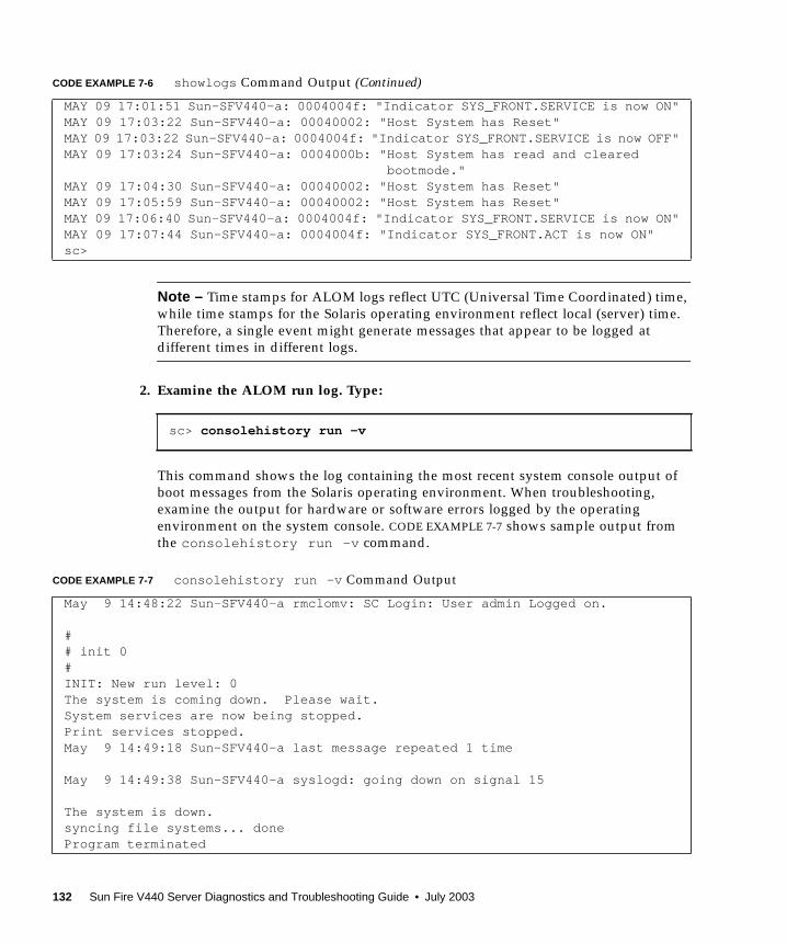
Note – Time stamps for ALOM logs reflect UTC (Universal Time Coordinated) time,
while time stamps for the Solaris operating environment reflect local (server) time.
Therefore, a single event might generate messages that appear to be logged at
different times in different logs.
2. Examine the ALOM run log. Type:
This command shows the log containing the most recent system console output of
boot messages from the Solaris operating environment. When troubleshooting,
examine the output for hardware or software errors logged by the operating
environment on the system console. CODE EXAMPLE 7-7 shows sample output from
the consolehistory run -v command.
MAY 09 17:01:51 Sun-SFV440-a: 0004004f: "Indicator SYS_FRONT.SERVICE is now ON"MAY 09 17:03:22 Sun-SFV440-a: 00040002: "Host System has Reset"MAY 09 17:03:22 Sun-SFV440-a: 0004004f: "Indicator SYS_FRONT.SERVICE is now OFF"MAY 09 17:03:24 Sun-SFV440-a: 0004000b: "Host System has read and cleared
bootmode."MAY 09 17:04:30 Sun-SFV440-a: 00040002: "Host System has Reset"MAY 09 17:05:59 Sun-SFV440-a: 00040002: "Host System has Reset"MAY 09 17:06:40 Sun-SFV440-a: 0004004f: "Indicator SYS_FRONT.SERVICE is now ON"MAY 09 17:07:44 Sun-SFV440-a: 0004004f: "Indicator SYS_FRONT.ACT is now ON"sc>
sc> consolehistory run -v
CODE EXAMPLE 7-7 consolehistory run -v Command Output
May 9 14:48:22 Sun-SFV440-a rmclomv: SC Login: User admin Logged on.
## init 0#INIT: New run level: 0The system is coming down. Please wait.System services are now being stopped.Print services stopped.May 9 14:49:18 Sun-SFV440-a last message repeated 1 time
May 9 14:49:38 Sun-SFV440-a syslogd: going down on signal 15
The system is down.syncing file systems... doneProgram terminated
CODE EXAMPLE 7-6 showlogs Command Output (Continued)
132 Sun Fire V440 Server Diagnostics and Troubleshooting Guide • July 2003
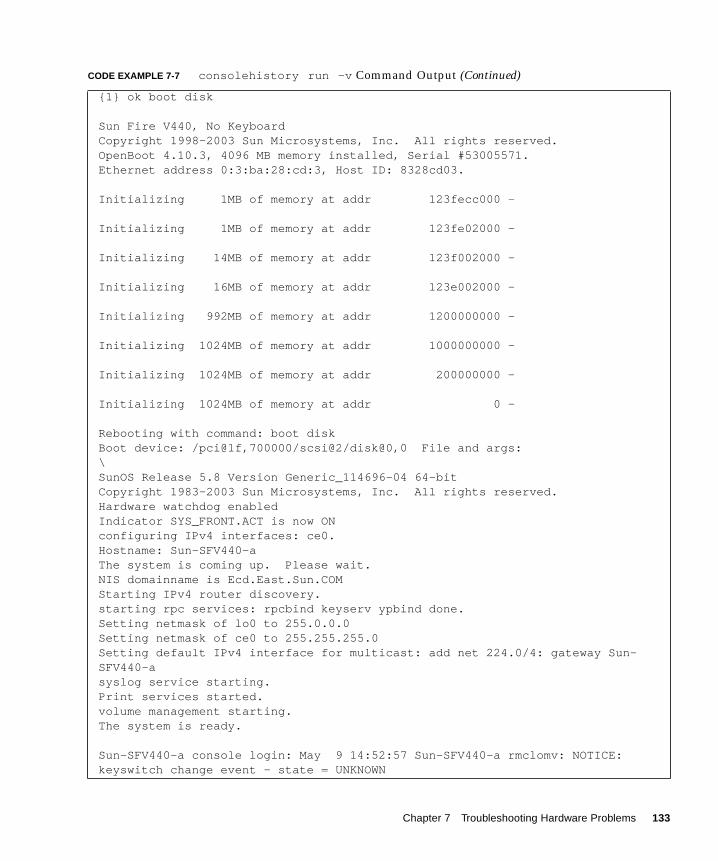
{1} ok boot disk
Sun Fire V440, No KeyboardCopyright 1998-2003 Sun Microsystems, Inc. All rights reserved.OpenBoot 4.10.3, 4096 MB memory installed, Serial #53005571.Ethernet address 0:3:ba:28:cd:3, Host ID: 8328cd03.
Initializing 1MB of memory at addr 123fecc000 -
Initializing 1MB of memory at addr 123fe02000 -
Initializing 14MB of memory at addr 123f002000 -
Initializing 16MB of memory at addr 123e002000 -
Initializing 992MB of memory at addr 1200000000 -
Initializing 1024MB of memory at addr 1000000000 -
Initializing 1024MB of memory at addr 200000000 -
Initializing 1024MB of memory at addr 0 -
Rebooting with command: boot diskBoot device: /pci@1f,700000/scsi@2/disk@0,0 File and args:\SunOS Release 5.8 Version Generic_114696-04 64-bitCopyright 1983-2003 Sun Microsystems, Inc. All rights reserved.Hardware watchdog enabledIndicator SYS_FRONT.ACT is now ONconfiguring IPv4 interfaces: ce0.Hostname: Sun-SFV440-aThe system is coming up. Please wait.NIS domainname is Ecd.East.Sun.COMStarting IPv4 router discovery.starting rpc services: rpcbind keyserv ypbind done.Setting netmask of lo0 to 255.0.0.0Setting netmask of ce0 to 255.255.255.0Setting default IPv4 interface for multicast: add net 224.0/4: gateway Sun-SFV440-asyslog service starting.Print services started.volume management starting.The system is ready.
Sun-SFV440-a console login: May 9 14:52:57 Sun-SFV440-a rmclomv: NOTICE:keyswitch change event - state = UNKNOWN
CODE EXAMPLE 7-7 consolehistory run -v Command Output (Continued)
Chapter 7 Troubleshooting Hardware Problems 133
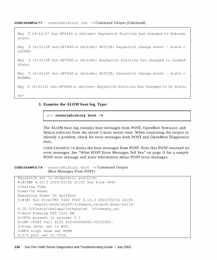
3. Examine the ALOM boot log. Type:
The ALOM boot log contains boot messages from POST, OpenBoot firmware, and
Solaris software from the server’s most recent reset. When examining the output to
identify a problem, check for error messages from POST and OpenBoot Diagnostics
tests.
CODE EXAMPLE 7-8 shows the boot messages from POST. Note that POST returned no
error messages. See “What POST Error Messages Tell You” on page 11 for a sample
POST error message and more information about POST error messages.
May 9 14:52:57 Sun-SFV440-a rmclomv: Keyswitch Position has changed to Unknownstate.
May 9 14:52:58 Sun-SFV440-a rmclomv: NOTICE: keyswitch change event - state =LOCKED
May 9 14:52:58 Sun-SFV440-a rmclomv: KeySwitch Position has changed to LockedState.
May 9 14:53:00 Sun-SFV440-a rmclomv: NOTICE: keyswitch change event - state =NORMAL
May 9 14:53:01 Sun-SFV440-a rmclomv: KeySwitch Position has changed to On State.
sc>
sc> consolehistory boot -v
CODE EXAMPLE 7-8 consolehistory boot -v Command Output(Boot Messages From POST)
Keyswitch set to diagnostic position.@(#)OBP 4.10.3 2003/05/02 20:25 Sun Fire V440Clearing TLBsPower-On ResetExecuting Power On SelfTest0>@(#) Sun Fire[TM] V440 POST 4.10.3 2003/05/04 22:08 /export/work/staff/firmware_re/post/post-build-4.10.3/Fiesta/chalupa/integrated (firmware_re)0>Hard Powerup RST thru SW0>CPUs present in system: 0 10>OBP->POST Call with %o0=00000000.01012000.0>Diag level set to MIN.0>MFG scrpt mode set NORM0>I/O port set to TTYA.
CODE EXAMPLE 7-7 consolehistory run -v Command Output (Continued)
134 Sun Fire V440 Server Diagnostics and Troubleshooting Guide • July 2003

CODE EXAMPLE 7-9 shows the initialization of the OpenBoot PROM.
The following sample output shows the system banner.
0>Start selftest...1>Print Mem Config1>Caches : Icache is ON, Dcache is ON, Wcache is ON, Pcache is ON.1>Memory interleave set to 01> Bank 0 1024MB : 00000010.00000000 -> 00000010.40000000.1> Bank 2 1024MB : 00000012.00000000 -> 00000012.40000000.0>Print Mem Config0>Caches : Icache is ON, Dcache is ON, Wcache is ON, Pcache is ON.0>Memory interleave set to 00> Bank 0 1024MB : 00000000.00000000 -> 00000000.40000000.0> Bank 2 1024MB : 00000002.00000000 -> 00000002.40000000.0>INFO:0> POST Passed all devices.0>POST: Return to OBP.
CODE EXAMPLE 7-9 consolehistory boot -v Command Output (OpenBoot PROM Initialization)
Keyswitch set to diagnostic position.@(#)OBP 4.10.3 2003/05/02 20:25 Sun Fire V440Clearing TLBsPOST Results: Cpu 0000.0000.0000.0000
%o0 = 0000.0000.0000.0000 %o1 = ffff.ffff.f00a.2b73 %o2 = ffff.ffff.ffff.ffffPOST Results: Cpu 0000.0000.0000.0001
%o0 = 0000.0000.0000.0000 %o1 = ffff.ffff.f00a.2b73 %o2 = ffff.ffff.ffff.ffffMembase: 0000.0000.0000.0000MemSize: 0000.0000.0004.0000Init CPU arrays DoneProbing /pci@1d,700000 Device 1 Nothing thereProbing /pci@1d,700000 Device 2 Nothing there
CODE EXAMPLE 7-10 consolehistory boot -v Command Output (System Banner Display)
Sun Fire V440, No KeyboardCopyright 1998-2003 Sun Microsystems, Inc. All rights reserved.OpenBoot 4.10.3, 4096 MB memory installed, Serial #53005571.Ethernet address 0:3:ba:28:cd:3, Host ID: 8328cd03.
CODE EXAMPLE 7-8 consolehistory boot -v Command Output(Boot Messages From POST) (Continued)
Chapter 7 Troubleshooting Hardware Problems 135
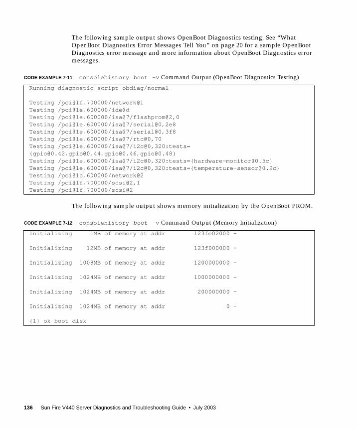
The following sample output shows OpenBoot Diagnostics testing. See “What
OpenBoot Diagnostics Error Messages Tell You” on page 20 for a sample OpenBoot
Diagnostics error message and more information about OpenBoot Diagnostics error
messages.
The following sample output shows memory initialization by the OpenBoot PROM.
CODE EXAMPLE 7-11 consolehistory boot -v Command Output (OpenBoot Diagnostics Testing)
Running diagnostic script obdiag/normal
Testing /pci@1f,700000/network@1Testing /pci@1e,600000/ide@dTesting /pci@1e,600000/isa@7/flashprom@2,0Testing /pci@1e,600000/isa@7/serial@0,2e8Testing /pci@1e,600000/isa@7/serial@0,3f8Testing /pci@1e,600000/isa@7/rtc@0,70Testing /pci@1e,600000/isa@7/i2c@0,320:tests={[email protected],[email protected],[email protected],[email protected]}Testing /pci@1e,600000/isa@7/i2c@0,320:tests={[email protected]}Testing /pci@1e,600000/isa@7/i2c@0,320:tests={[email protected]}Testing /pci@1c,600000/network@2Testing /pci@1f,700000/scsi@2,1Testing /pci@1f,700000/scsi@2
CODE EXAMPLE 7-12 consolehistory boot -v Command Output (Memory Initialization)
Initializing 1MB of memory at addr 123fe02000 -
Initializing 12MB of memory at addr 123f000000 -
Initializing 1008MB of memory at addr 1200000000 -
Initializing 1024MB of memory at addr 1000000000 -
Initializing 1024MB of memory at addr 200000000 -
Initializing 1024MB of memory at addr 0 -
{1} ok boot disk
136 Sun Fire V440 Server Diagnostics and Troubleshooting Guide • July 2003
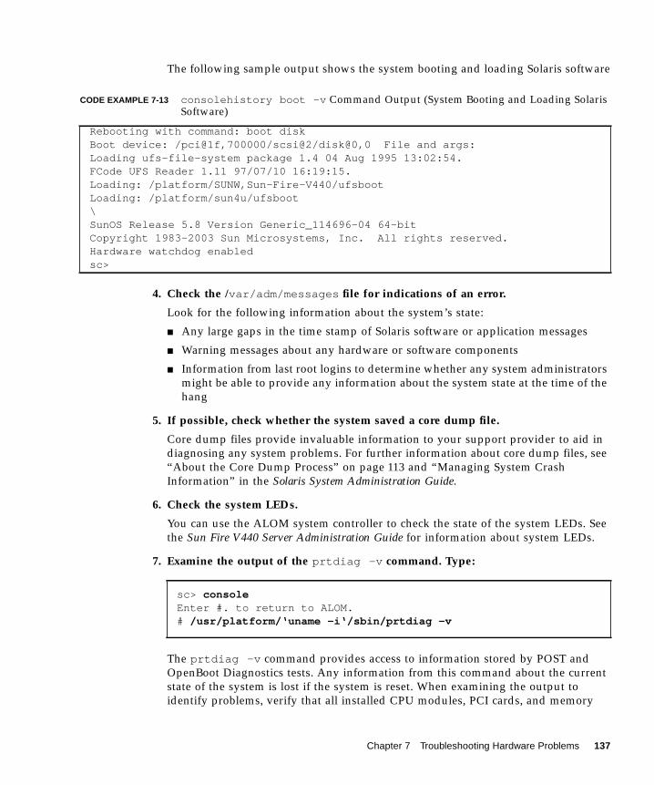
The following sample output shows the system booting and loading Solaris software
4. Check the /var/adm/messages file for indications of an error.
Look for the following information about the system’s state:
■ Any large gaps in the time stamp of Solaris software or application messages
■ Warning messages about any hardware or software components
■ Information from last root logins to determine whether any system administrators
might be able to provide any information about the system state at the time of the
hang
5. If possible, check whether the system saved a core dump file.
Core dump files provide invaluable information to your support provider to aid in
diagnosing any system problems. For further information about core dump files, see
“About the Core Dump Process” on page 113 and “Managing System Crash
Information” in the Solaris System Administration Guide.
6. Check the system LEDs.
You can use the ALOM system controller to check the state of the system LEDs. See
the Sun Fire V440 Server Administration Guide for information about system LEDs.
7. Examine the output of the prtdiag -v command. Type:
The prtdiag -v command provides access to information stored by POST and
OpenBoot Diagnostics tests. Any information from this command about the current
state of the system is lost if the system is reset. When examining the output to
identify problems, verify that all installed CPU modules, PCI cards, and memory
CODE EXAMPLE 7-13 consolehistory boot -v Command Output (System Booting and Loading SolarisSoftware)
Rebooting with command: boot diskBoot device: /pci@1f,700000/scsi@2/disk@0,0 File and args:Loading ufs-file-system package 1.4 04 Aug 1995 13:02:54.FCode UFS Reader 1.11 97/07/10 16:19:15.Loading: /platform/SUNW,Sun-Fire-V440/ufsbootLoading: /platform/sun4u/ufsboot\SunOS Release 5.8 Version Generic_114696-04 64-bitCopyright 1983-2003 Sun Microsystems, Inc. All rights reserved.Hardware watchdog enabledsc>
sc> consoleEnter #. to return to ALOM.# /usr/platform/‘uname -i‘/sbin/prtdiag -v
Chapter 7 Troubleshooting Hardware Problems 137
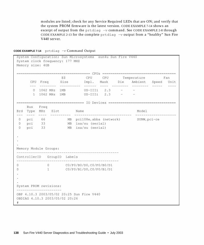
modules are listed; check for any Service Required LEDs that are ON; and verify that
the system PROM firmware is the latest version. CODE EXAMPLE 7-14 shows an
excerpt of output from the prtdiag -v command. See CODE EXAMPLE 2-8 through
CODE EXAMPLE 2-13 for the complete prtdiag -v output from a “healthy” Sun Fire
V440 server.
CODE EXAMPLE 7-14 prtdiag -v Command Output
System Configuration: Sun Microsystems sun4u Sun Fire V440System clock frequency: 177 MHZMemory size: 4GB
==================================== CPUs ==================================== E$ CPU CPU Temperature Fan
CPU Freq Size Impl. Mask Die Ambient Speed Unit--- -------- ---------- ------ ---- -------- -------- ----- ----
0 1062 MHz 1MB US-IIIi 2.3 - - 1 1062 MHz 1MB US-IIIi 2.3 - -
================================= IO Devices ================================= Bus FreqBrd Type MHz Slot Name Model--- ---- ---- ---------- ---------------------------- -------------------- 0 pci 66 MB pci108e,abba (network) SUNW,pci-ce 0 pci 33 MB isa/su (serial) 0 pci 33 MB isa/su (serial)
.
.
.Memory Module Groups:--------------------------------------------------ControllerID GroupID Labels--------------------------------------------------0 0 C0/P0/B0/D0,C0/P0/B0/D10 1 C0/P0/B1/D0,C0/P0/B1/D1...System PROM revisions:----------------------OBP 4.10.3 2003/05/02 20:25 Sun Fire V440OBDIAG 4.10.3 2003/05/02 20:26#
138 Sun Fire V440 Server Diagnostics and Troubleshooting Guide • July 2003

8. Verify that all user and system processes are functional. Type:
Output from the ps -ef command shows each process, the start time, the run time,
and the full process command-line options. To identify a system problem, examine
the output for missing entries in the CMDcolumn. CODE EXAMPLE 7-15 shows the
ps -ef command output of a “healthy” Sun Fire V440 server.
# ps -ef
CODE EXAMPLE 7-15 ps -ef Command Output
UID PID PPID C STIME TTY TIME CMD root 0 0 0 14:51:32 ? 0:17 sched root 1 0 0 14:51:32 ? 0:00 /etc/init - root 2 0 0 14:51:32 ? 0:00 pageout root 3 0 0 14:51:32 ? 0:02 fsflush root 291 1 0 14:51:47 ? 0:00 /usr/lib/saf/sac -t 300 root 205 1 0 14:51:44 ? 0:00 /usr/lib/lpsched root 312 148 0 14:54:33 ? 0:00 in.telnetd root 169 1 0 14:51:42 ? 0:00 /usr/lib/autofs/automountd user1 314 312 0 14:54:33 pts/1 0:00 -csh root 53 1 0 14:51:36 ? 0:00 /usr/lib/sysevent/syseventd root 59 1 0 14:51:37 ? 0:02 /usr/lib/picl/picld root 100 1 0 14:51:40 ? 0:00 /usr/sbin/in.rdisc -s
root 131 1 0 14:51:40 ? 0:00 /usr/lib/netsvc/yp/ypbind -broadcast root 118 1 0 14:51:40 ? 0:00 /usr/sbin/rpcbind root 121 1 0 14:51:40 ? 0:00 /usr/sbin/keyserv root 148 1 0 14:51:42 ? 0:00 /usr/sbin/inetd -s root 218 1 0 14:51:44 ? 0:00 /usr/lib/power/powerd root 199 1 0 14:51:43 ? 0:00 /usr/sbin/nscd root 162 1 0 14:51:42 ? 0:00 /usr/lib/nfs/lockd daemon 166 1 0 14:51:42 ? 0:00 /usr/lib/nfs/statd root 181 1 0 14:51:43 ? 0:00 /usr/sbin/syslogd root 283 1 0 14:51:47 ? 0:00 /usr/lib/dmi/snmpXdmid -s Sun-SFV440-a root 184 1 0 14:51:43 ? 0:00 /usr/sbin/cron root 235 233 0 14:51:44 ? 0:00 /usr/sadm/lib/smc/bin/smcboot root 233 1 0 14:51:44 ? 0:00 /usr/sadm/lib/smc/bin/smcboot root 245 1 0 14:51:45 ? 0:00 /usr/sbin/vold root 247 1 0 14:51:45 ? 0:00 /usr/lib/sendmail -bd -q15m
root 256 1 0 14:51:45 ? 0:00 /usr/lib/efcode/sparcv9/efdaemon root 294 291 0 14:51:47 ? 0:00 /usr/lib/saf/ttymon root 304 274 0 14:51:51 ? 0:00 mibiisa -r -p 32826 root 274 1 0 14:51:46 ? 0:00 /usr/lib/snmp/snmpdx -y -c/etc/snmp/conf root 334 292 0 15:00:59 console 0:00 ps -ef#
Chapter 7 Troubleshooting Hardware Problems 139

9. Verify that all I/O devices and activities are still present and functioning. Type:
This command shows all I/O devices and reports activity for each device. To
identify a problem, examine the output for installed devices that are not listed.
CODE EXAMPLE 7-16 shows the iostat -xtc command output from a “healthy” Sun
Fire V440 server.
10. Examine errors pertaining to I/O devices. Type:
This command reports on errors for each I/O device. To identify a problem, examine
the output for any type of error that is more than 0. For example, in
CODE EXAMPLE 7-17, iostat -E reports Hard Errors: 2 for I/O device sd0 .
# iostat -xtc
CODE EXAMPLE 7-16 iostat -xtc Command Output
extended device statistics tty cpudevice r/s w/s kr/s kw/s wait actv svc_t %w %b tin tout us sy wt idsd0 0.0 0.0 0.0 0.0 0.0 0.0 0.0 0 0 0 183 0 2 2 96sd1 6.5 1.2 49.5 7.9 0.0 0.2 24.6 0 3sd2 0.2 0.0 0.0 0.0 0.0 0.0 0.0 0 0sd3 0.2 0.0 0.0 0.0 0.0 0.0 0.0 0 0sd4 0.2 0.0 0.0 0.0 0.0 0.0 0.0 0 0nfs1 0.0 0.0 0.0 0.0 0.0 0.0 0.0 0 0nfs2 0.0 0.0 0.1 0.0 0.0 0.0 9.6 0 0nfs3 0.1 0.0 0.6 0.0 0.0 0.0 1.4 0 0nfs4 0.0 0.0 0.1 0.0 0.0 0.0 5.1 0 0#
# iostat -E
CODE EXAMPLE 7-17 iostat -E Command Output
sd0 Soft Errors: 0 Hard Errors: 2 Transport Errors: 0Vendor: TOSHIBA Product: DVD-ROM SD-C2612 Revision: 1011 Serial No: 04/17/02Size: 18446744073.71GB <-1 bytes>Media Error: 0 Device Not Ready: 2 No Device: 0 Recoverable: 0Illegal Request: 0 Predictive Failure Analysis: 0sd1 Soft Errors: 0 Hard Errors: 0 Transport Errors: 0Vendor: SEAGATE Product: ST336607LSUN36G Revision: 0207 Serial No:3JA0BW6Y00002317Size: 36.42GB <36418595328 bytes>Media Error: 0 Device Not Ready: 0 No Device: 0 Recoverable: 0Illegal Request: 0 Predictive Failure Analysis: 0sd2 Soft Errors: 0 Hard Errors: 0 Transport Errors: 0
140 Sun Fire V440 Server Diagnostics and Troubleshooting Guide • July 2003
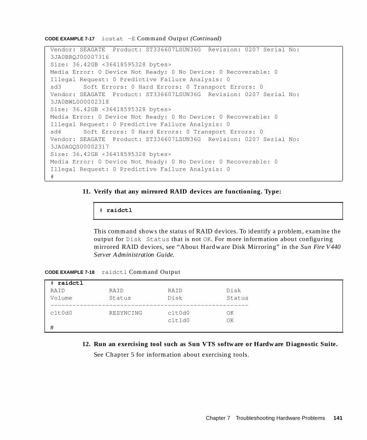
11. Verify that any mirrored RAID devices are functioning. Type:
This command shows the status of RAID devices. To identify a problem, examine the
output for Disk Status that is not OK. For more information about configuring
mirrored RAID devices, see “About Hardware Disk Mirroring” in the Sun Fire V440Server Administration Guide.
12. Run an exercising tool such as Sun VTS software or Hardware Diagnostic Suite.
See Chapter 5 for information about exercising tools.
Vendor: SEAGATE Product: ST336607LSUN36G Revision: 0207 Serial No:3JA0BRQJ00007316Size: 36.42GB <36418595328 bytes>Media Error: 0 Device Not Ready: 0 No Device: 0 Recoverable: 0Illegal Request: 0 Predictive Failure Analysis: 0sd3 Soft Errors: 0 Hard Errors: 0 Transport Errors: 0Vendor: SEAGATE Product: ST336607LSUN36G Revision: 0207 Serial No:3JA0BWL000002318Size: 36.42GB <36418595328 bytes>Media Error: 0 Device Not Ready: 0 No Device: 0 Recoverable: 0Illegal Request: 0 Predictive Failure Analysis: 0sd4 Soft Errors: 0 Hard Errors: 0 Transport Errors: 0Vendor: SEAGATE Product: ST336607LSUN36G Revision: 0207 Serial No:3JA0AGQS00002317Size: 36.42GB <36418595328 bytes>Media Error: 0 Device Not Ready: 0 No Device: 0 Recoverable: 0Illegal Request: 0 Predictive Failure Analysis: 0#
# raidctl
CODE EXAMPLE 7-18 raidctl Command Output
# raidctlRAID RAID RAID DiskVolume Status Disk Status------------------------------------------------------c1t0d0 RESYNCING c1t0d0 OK c1t1d0 OK#
CODE EXAMPLE 7-17 iostat -E Command Output (Continued)
Chapter 7 Troubleshooting Hardware Problems 141
13. If this is the first occurrence of an unexpected reboot and the system did not runPOST as part of the reboot process, run POST.
If ASR is not enabled, now is a good time to enable ASR. ASR runs POST and
OpenBoot Diagnostics tests automatically at reboot. With ASR enabled, you can save
time diagnosing problems since POST and OpenBoot Diagnostics test results are
already available after an unexpected reboot. See the Sun Fire V440 ServerAdministration Guide for more information about ASR and complete instructions for
enabling ASR.
What Next
Schedule maintenance as necessary for any service actions.
How to Troubleshoot Fatal Reset Errorsand RED State Exceptions
Before You Begin
Log in to the system controller and access the sc> prompt. For information, see:
■ “About the sc> Prompt” on page 169
This procedure assumes that the system console is in its default configuration, so
that you are able to switch between the system controller and the system console.
See:
■ “About Communicating With the System” on page 164
■ “Access Through the Network Management Port” on page 168
For more information about Fatal Reset errors and RED State Exceptions, see
“Responding to Fatal Reset Errors and RED State Exceptions” on page 124. For a
sample Fatal Reset error message, see CODE EXAMPLE 7-1. For a sample RED State
Exception message, see CODE EXAMPLE 7-2.
142 Sun Fire V440 Server Diagnostics and Troubleshooting Guide • July 2003

What to Do
1. Examine the ALOM event log. Type:
The ALOM event log shows system events such as reset events and LED indicator
state changes that have occurred since the last system boot. CODE EXAMPLE 7-19
shows a sample event log, which indicates that the front panel Service Required LED
is ON.
Note – Time stamps for ALOM logs reflect UTC (Universal Time Coordinated) time,
while time stamps for the Solaris operating environment reflect local (server) time.
Therefore, a single event might generate messages that appear to be logged at
different times in different logs.
sc> showlogs
CODE EXAMPLE 7-19 showlogs Command Output
MAY 09 16:54:27 Sun-SFV440-a: 00060003: "SC System booted."MAY 09 16:54:27 Sun-SFV440-a: 00040029: "Host system has shut down."MAY 09 16:56:35 Sun-SFV440-a: 00060000: "SC Login: User admin Logged on."MAY 09 16:56:54 Sun-SFV440-a: 00060000: "SC Login: User admin Logged on."MAY 09 16:58:11 Sun-SFV440-a: 00040001: "SC Request to Power On Host."MAY 09 16:58:11 Sun-SFV440-a: 00040002: "Host System has Reset"MAY 09 16:58:13 Sun-SFV440-a: 0004000b: "Host System has read and cleared
bootmode."MAY 09 16:58:13 Sun-SFV440-a: 0004004f: "Indicator PS0.POK is now ON"MAY 09 16:58:13 Sun-SFV440-a: 0004004f: "Indicator PS1.POK is now ON"MAY 09 16:59:19 Sun-SFV440-a: 00040002: "Host System has Reset"MAY 09 17:00:46 Sun-SFV440-a: 00040002: "Host System has Reset"MAY 09 17:01:51 Sun-SFV440-a: 0004004f: "Indicator SYS_FRONT.SERVICE is now ON"MAY 09 17:03:22 Sun-SFV440-a: 00040002: "Host System has Reset"MAY 09 17:03:22 Sun-SFV440-a: 0004004f: "Indicator SYS_FRONT.SERVICE is now OFF"MAY 09 17:03:24 Sun-SFV440-a: 0004000b: "Host System has read and cleared
bootmode."MAY 09 17:04:30 Sun-SFV440-a: 00040002: "Host System has Reset"MAY 09 17:05:59 Sun-SFV440-a: 00040002: "Host System has Reset"MAY 09 17:06:40 Sun-SFV440-a: 0004004f: "Indicator SYS_FRONT.SERVICE is now ON"MAY 09 17:07:44 Sun-SFV440-a: 0004004f: "Indicator SYS_FRONT.ACT is now ON"sc>
Chapter 7 Troubleshooting Hardware Problems 143
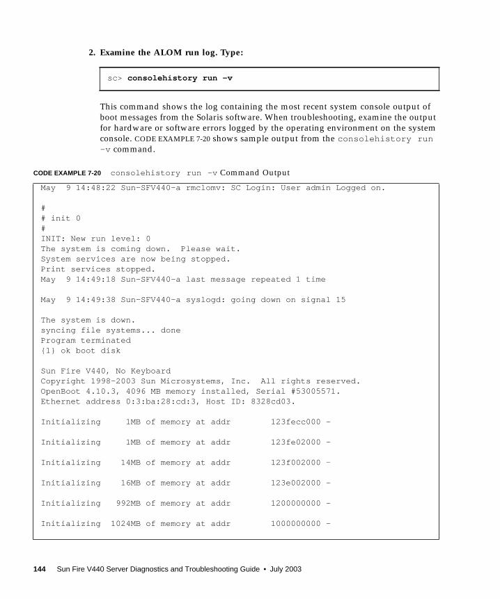
2. Examine the ALOM run log. Type:
This command shows the log containing the most recent system console output of
boot messages from the Solaris software. When troubleshooting, examine the output
for hardware or software errors logged by the operating environment on the system
console. CODE EXAMPLE 7-20 shows sample output from the consolehistory run-v command.
sc> consolehistory run -v
CODE EXAMPLE 7-20 consolehistory run -v Command Output
May 9 14:48:22 Sun-SFV440-a rmclomv: SC Login: User admin Logged on.
## init 0#INIT: New run level: 0The system is coming down. Please wait.System services are now being stopped.Print services stopped.May 9 14:49:18 Sun-SFV440-a last message repeated 1 time
May 9 14:49:38 Sun-SFV440-a syslogd: going down on signal 15
The system is down.syncing file systems... doneProgram terminated{1} ok boot disk
Sun Fire V440, No KeyboardCopyright 1998-2003 Sun Microsystems, Inc. All rights reserved.OpenBoot 4.10.3, 4096 MB memory installed, Serial #53005571.Ethernet address 0:3:ba:28:cd:3, Host ID: 8328cd03.
Initializing 1MB of memory at addr 123fecc000 -
Initializing 1MB of memory at addr 123fe02000 -
Initializing 14MB of memory at addr 123f002000 -
Initializing 16MB of memory at addr 123e002000 -
Initializing 992MB of memory at addr 1200000000 -
Initializing 1024MB of memory at addr 1000000000 -
144 Sun Fire V440 Server Diagnostics and Troubleshooting Guide • July 2003
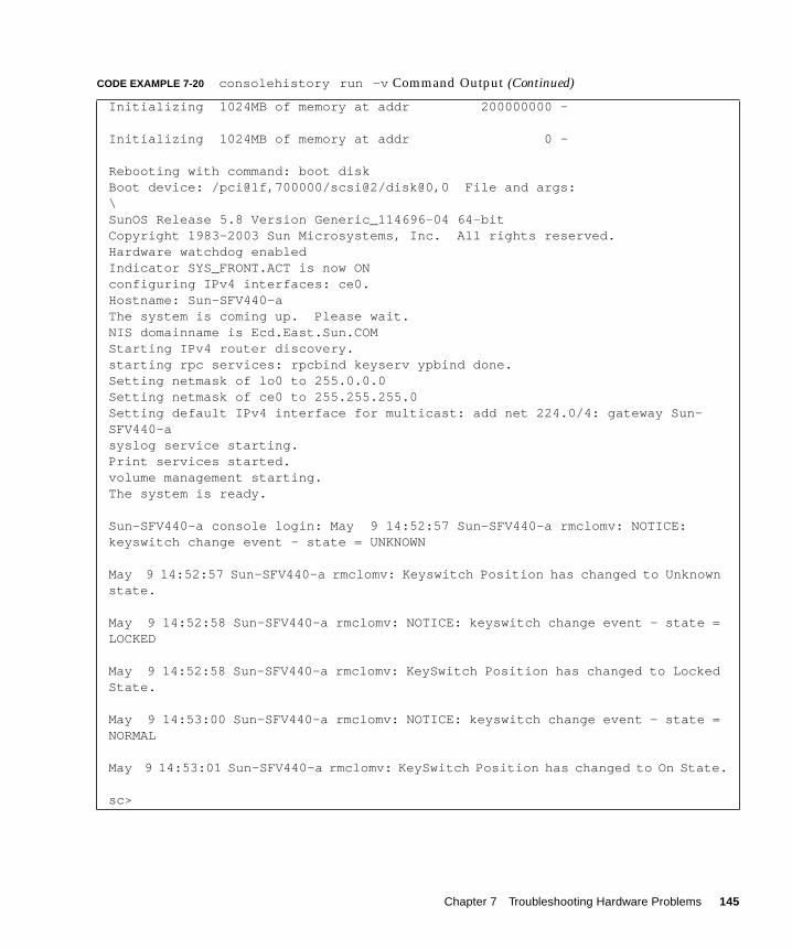
Initializing 1024MB of memory at addr 200000000 -
Initializing 1024MB of memory at addr 0 -
Rebooting with command: boot diskBoot device: /pci@1f,700000/scsi@2/disk@0,0 File and args:\SunOS Release 5.8 Version Generic_114696-04 64-bitCopyright 1983-2003 Sun Microsystems, Inc. All rights reserved.Hardware watchdog enabledIndicator SYS_FRONT.ACT is now ONconfiguring IPv4 interfaces: ce0.Hostname: Sun-SFV440-aThe system is coming up. Please wait.NIS domainname is Ecd.East.Sun.COMStarting IPv4 router discovery.starting rpc services: rpcbind keyserv ypbind done.Setting netmask of lo0 to 255.0.0.0Setting netmask of ce0 to 255.255.255.0Setting default IPv4 interface for multicast: add net 224.0/4: gateway Sun-SFV440-asyslog service starting.Print services started.volume management starting.The system is ready.
Sun-SFV440-a console login: May 9 14:52:57 Sun-SFV440-a rmclomv: NOTICE:keyswitch change event - state = UNKNOWN
May 9 14:52:57 Sun-SFV440-a rmclomv: Keyswitch Position has changed to Unknownstate.
May 9 14:52:58 Sun-SFV440-a rmclomv: NOTICE: keyswitch change event - state =LOCKED
May 9 14:52:58 Sun-SFV440-a rmclomv: KeySwitch Position has changed to LockedState.
May 9 14:53:00 Sun-SFV440-a rmclomv: NOTICE: keyswitch change event - state =NORMAL
May 9 14:53:01 Sun-SFV440-a rmclomv: KeySwitch Position has changed to On State.
sc>
CODE EXAMPLE 7-20 consolehistory run -v Command Output (Continued)
Chapter 7 Troubleshooting Hardware Problems 145
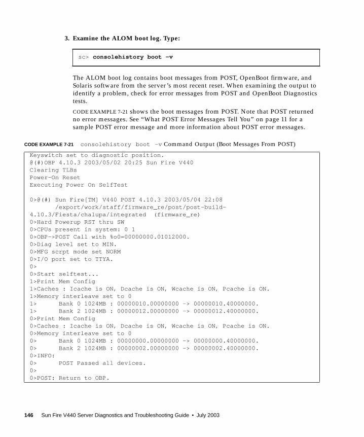
3. Examine the ALOM boot log. Type:
The ALOM boot log contains boot messages from POST, OpenBoot firmware, and
Solaris software from the server’s most recent reset. When examining the output to
identify a problem, check for error messages from POST and OpenBoot Diagnostics
tests.
CODE EXAMPLE 7-21 shows the boot messages from POST. Note that POST returned
no error messages. See “What POST Error Messages Tell You” on page 11 for a
sample POST error message and more information about POST error messages.
sc> consolehistory boot -v
CODE EXAMPLE 7-21 consolehistory boot -v Command Output (Boot Messages From POST)
Keyswitch set to diagnostic position.@(#)OBP 4.10.3 2003/05/02 20:25 Sun Fire V440Clearing TLBsPower-On ResetExecuting Power On SelfTest
0>@(#) Sun Fire[TM] V440 POST 4.10.3 2003/05/04 22:08 /export/work/staff/firmware_re/post/post-build-4.10.3/Fiesta/chalupa/integrated (firmware_re)0>Hard Powerup RST thru SW0>CPUs present in system: 0 10>OBP->POST Call with %o0=00000000.01012000.0>Diag level set to MIN.0>MFG scrpt mode set NORM0>I/O port set to TTYA.0>0>Start selftest...1>Print Mem Config1>Caches : Icache is ON, Dcache is ON, Wcache is ON, Pcache is ON.1>Memory interleave set to 01> Bank 0 1024MB : 00000010.00000000 -> 00000010.40000000.1> Bank 2 1024MB : 00000012.00000000 -> 00000012.40000000.0>Print Mem Config0>Caches : Icache is ON, Dcache is ON, Wcache is ON, Pcache is ON.0>Memory interleave set to 00> Bank 0 1024MB : 00000000.00000000 -> 00000000.40000000.0> Bank 2 1024MB : 00000002.00000000 -> 00000002.40000000.0>INFO:0> POST Passed all devices.0>0>POST: Return to OBP.
146 Sun Fire V440 Server Diagnostics and Troubleshooting Guide • July 2003
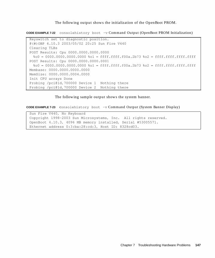
The following output shows the initialization of the OpenBoot PROM.
The following sample output shows the system banner.
CODE EXAMPLE 7-22 consolehistory boot -v Command Output (OpenBoot PROM Initialization)
Keyswitch set to diagnostic position.@(#)OBP 4.10.3 2003/05/02 20:25 Sun Fire V440Clearing TLBsPOST Results: Cpu 0000.0000.0000.0000
%o0 = 0000.0000.0000.0000 %o1 = ffff.ffff.f00a.2b73 %o2 = ffff.ffff.ffff.ffffPOST Results: Cpu 0000.0000.0000.0001
%o0 = 0000.0000.0000.0000 %o1 = ffff.ffff.f00a.2b73 %o2 = ffff.ffff.ffff.ffffMembase: 0000.0000.0000.0000MemSize: 0000.0000.0004.0000Init CPU arrays DoneProbing /pci@1d,700000 Device 1 Nothing thereProbing /pci@1d,700000 Device 2 Nothing there
CODE EXAMPLE 7-23 consolehistory boot -v Command Output (System Banner Display)
Sun Fire V440, No KeyboardCopyright 1998-2003 Sun Microsystems, Inc. All rights reserved.OpenBoot 4.10.3, 4096 MB memory installed, Serial #53005571.Ethernet address 0:3:ba:28:cd:3, Host ID: 8328cd03.
Chapter 7 Troubleshooting Hardware Problems 147

The following sample output shows OpenBoot Diagnostics testing. See “What
OpenBoot Diagnostics Error Messages Tell You” on page 20 for a sample OpenBoot
Diagnostics error message and more information about OpenBoot Diagnostics error
messages.
The following sample output shows memory initialization by the OpenBoot PROM.
CODE EXAMPLE 7-24 consolehistory boot -v Command Output (OpenBoot Diagnostics Testing)
Running diagnostic script obdiag/normal
Testing /pci@1f,700000/network@1Testing /pci@1e,600000/ide@dTesting /pci@1e,600000/isa@7/flashprom@2,0Testing /pci@1e,600000/isa@7/serial@0,2e8Testing /pci@1e,600000/isa@7/serial@0,3f8Testing /pci@1e,600000/isa@7/rtc@0,70Testing /pci@1e,600000/isa@7/i2c@0,320:tests={[email protected],[email protected],[email protected],[email protected]}Testing /pci@1e,600000/isa@7/i2c@0,320:tests={[email protected]}Testing /pci@1e,600000/isa@7/i2c@0,320:tests={[email protected]}Testing /pci@1c,600000/network@2Testing /pci@1f,700000/scsi@2,1Testing /pci@1f,700000/scsi@2
CODE EXAMPLE 7-25 consolehistory boot -v Command Output (Memory Initialization)
Initializing 1MB of memory at addr 123fe02000 -
Initializing 12MB of memory at addr 123f000000 -
Initializing 1008MB of memory at addr 1200000000 -
Initializing 1024MB of memory at addr 1000000000 -
Initializing 1024MB of memory at addr 200000000 -
Initializing 1024MB of memory at addr 0 -
{1} ok boot disk
148 Sun Fire V440 Server Diagnostics and Troubleshooting Guide • July 2003
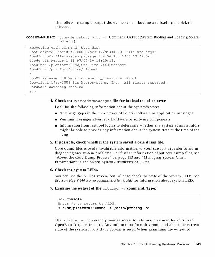
The following sample output shows the system booting and loading the Solaris
software.
4. Check the /var/adm/messages file for indications of an error.
Look for the following information about the system’s state:
■ Any large gaps in the time stamp of Solaris software or application messages
■ Warning messages about any hardware or software components
■ Information from last root logins to determine whether any system administrators
might be able to provide any information about the system state at the time of the
hang
5. If possible, check whether the system saved a core dump file.
Core dump files provide invaluable information to your support provider to aid in
diagnosing any system problems. For further information about core dump files, see
“About the Core Dump Process” on page 113 and “Managing System Crash
Information” in the Solaris System Administration Guide.
6. Check the system LEDs.
You can use the ALOM system controller to check the state of the system LEDs. See
the Sun Fire V440 Server Administration Guide for information about system LEDs.
7. Examine the output of the prtdiag -v command. Type:
The prtdiag -v command provides access to information stored by POST and
OpenBoot Diagnostics tests. Any information from this command about the current
state of the system is lost if the system is reset. When examining the output to
CODE EXAMPLE 7-26 consolehistory boot -v Command Output (System Booting and Loading SolarisSoftware)
Rebooting with command: boot diskBoot device: /pci@1f,700000/scsi@2/disk@0,0 File and args:Loading ufs-file-system package 1.4 04 Aug 1995 13:02:54.FCode UFS Reader 1.11 97/07/10 16:19:15.Loading: /platform/SUNW,Sun-Fire-V440/ufsbootLoading: /platform/sun4u/ufsboot\SunOS Release 5.8 Version Generic_114696-04 64-bitCopyright 1983-2003 Sun Microsystems, Inc. All rights reserved.Hardware watchdog enabledsc>
sc> consoleEnter #. to return to ALOM.# /usr/platform/‘uname -i‘/sbin/prtdiag -v
Chapter 7 Troubleshooting Hardware Problems 149
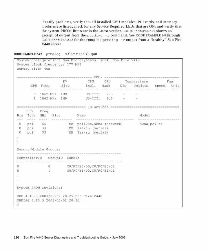
identify problems, verify that all installed CPU modules, PCI cards, and memory
modules are listed; check for any Service Required LEDs that are ON; and verify that
the system PROM firmware is the latest version. CODE EXAMPLE 7-27 shows an
excerpt of output from the prtdiag -v command. See CODE EXAMPLE 2-8 through
CODE EXAMPLE 2-13 for the complete prtdiag -v output from a “healthy” Sun Fire
V440 server.
CODE EXAMPLE 7-27 prtdiag -v Command Output
System Configuration: Sun Microsystems sun4u Sun Fire V440System clock frequency: 177 MHZMemory size: 4GB
==================================== CPUs ==================================== E$ CPU CPU Temperature Fan
CPU Freq Size Impl. Mask Die Ambient Speed Unit--- -------- ---------- ------ ---- -------- -------- ----- ----
0 1062 MHz 1MB US-IIIi 2.3 - - 1 1062 MHz 1MB US-IIIi 2.3 - -
================================= IO Devices ================================= Bus FreqBrd Type MHz Slot Name Model--- ---- ---- ---------- ---------------------------- -------------------- 0 pci 66 MB pci108e,abba (network) SUNW,pci-ce 0 pci 33 MB isa/su (serial) 0 pci 33 MB isa/su (serial)...Memory Module Groups:--------------------------------------------------ControllerID GroupID Labels--------------------------------------------------0 0 C0/P0/B0/D0,C0/P0/B0/D10 1 C0/P0/B1/D0,C0/P0/B1/D1...System PROM revisions:----------------------OBP 4.10.3 2003/05/02 20:25 Sun Fire V440OBDIAG 4.10.3 2003/05/02 20:26#
150 Sun Fire V440 Server Diagnostics and Troubleshooting Guide • July 2003
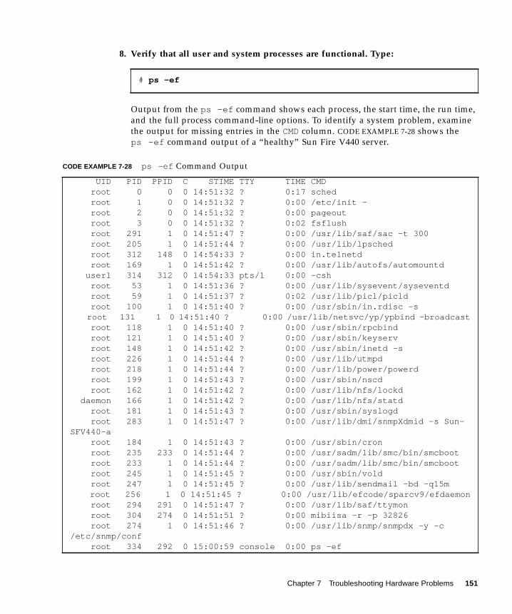
8. Verify that all user and system processes are functional. Type:
Output from the ps -ef command shows each process, the start time, the run time,
and the full process command-line options. To identify a system problem, examine
the output for missing entries in the CMDcolumn. CODE EXAMPLE 7-28 shows the
ps -ef command output of a “healthy” Sun Fire V440 server.
# ps -ef
CODE EXAMPLE 7-28 ps -ef Command Output
UID PID PPID C STIME TTY TIME CMD root 0 0 0 14:51:32 ? 0:17 sched root 1 0 0 14:51:32 ? 0:00 /etc/init - root 2 0 0 14:51:32 ? 0:00 pageout root 3 0 0 14:51:32 ? 0:02 fsflush root 291 1 0 14:51:47 ? 0:00 /usr/lib/saf/sac -t 300 root 205 1 0 14:51:44 ? 0:00 /usr/lib/lpsched root 312 148 0 14:54:33 ? 0:00 in.telnetd root 169 1 0 14:51:42 ? 0:00 /usr/lib/autofs/automountd user1 314 312 0 14:54:33 pts/1 0:00 -csh root 53 1 0 14:51:36 ? 0:00 /usr/lib/sysevent/syseventd root 59 1 0 14:51:37 ? 0:02 /usr/lib/picl/picld root 100 1 0 14:51:40 ? 0:00 /usr/sbin/in.rdisc -s
root 131 1 0 14:51:40 ? 0:00 /usr/lib/netsvc/yp/ypbind -broadcast root 118 1 0 14:51:40 ? 0:00 /usr/sbin/rpcbind root 121 1 0 14:51:40 ? 0:00 /usr/sbin/keyserv root 148 1 0 14:51:42 ? 0:00 /usr/sbin/inetd -s root 226 1 0 14:51:44 ? 0:00 /usr/lib/utmpd root 218 1 0 14:51:44 ? 0:00 /usr/lib/power/powerd root 199 1 0 14:51:43 ? 0:00 /usr/sbin/nscd root 162 1 0 14:51:42 ? 0:00 /usr/lib/nfs/lockd daemon 166 1 0 14:51:42 ? 0:00 /usr/lib/nfs/statd root 181 1 0 14:51:43 ? 0:00 /usr/sbin/syslogd root 283 1 0 14:51:47 ? 0:00 /usr/lib/dmi/snmpXdmid -s Sun-SFV440-a root 184 1 0 14:51:43 ? 0:00 /usr/sbin/cron root 235 233 0 14:51:44 ? 0:00 /usr/sadm/lib/smc/bin/smcboot root 233 1 0 14:51:44 ? 0:00 /usr/sadm/lib/smc/bin/smcboot root 245 1 0 14:51:45 ? 0:00 /usr/sbin/vold root 247 1 0 14:51:45 ? 0:00 /usr/lib/sendmail -bd -q15m
root 256 1 0 14:51:45 ? 0:00 /usr/lib/efcode/sparcv9/efdaemon root 294 291 0 14:51:47 ? 0:00 /usr/lib/saf/ttymon root 304 274 0 14:51:51 ? 0:00 mibiisa -r -p 32826 root 274 1 0 14:51:46 ? 0:00 /usr/lib/snmp/snmpdx -y -c/etc/snmp/conf root 334 292 0 15:00:59 console 0:00 ps -ef
Chapter 7 Troubleshooting Hardware Problems 151
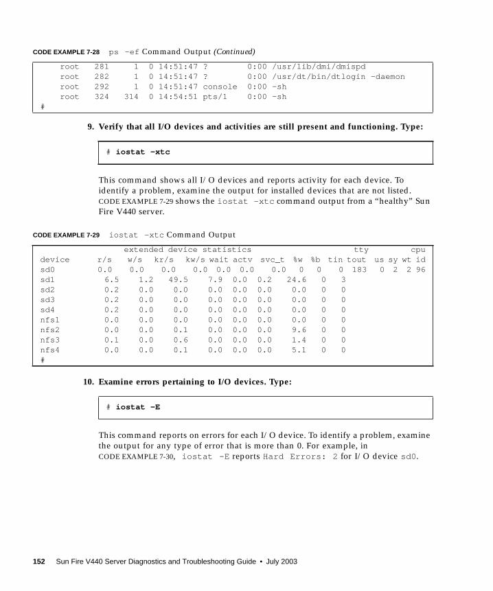
9. Verify that all I/O devices and activities are still present and functioning. Type:
This command shows all I/O devices and reports activity for each device. To
identify a problem, examine the output for installed devices that are not listed.
CODE EXAMPLE 7-29 shows the iostat -xtc command output from a “healthy” Sun
Fire V440 server.
10. Examine errors pertaining to I/O devices. Type:
This command reports on errors for each I/O device. To identify a problem, examine
the output for any type of error that is more than 0. For example, in
CODE EXAMPLE 7-30, iostat -E reports Hard Errors: 2 for I/O device sd0 .
root 281 1 0 14:51:47 ? 0:00 /usr/lib/dmi/dmispd root 282 1 0 14:51:47 ? 0:00 /usr/dt/bin/dtlogin -daemon root 292 1 0 14:51:47 console 0:00 -sh root 324 314 0 14:54:51 pts/1 0:00 -sh#
# iostat -xtc
CODE EXAMPLE 7-29 iostat -xtc Command Output
extended device statistics tty cpudevice r/s w/s kr/s kw/s wait actv svc_t %w %b tin tout us sy wt idsd0 0.0 0.0 0.0 0.0 0.0 0.0 0.0 0 0 0 183 0 2 2 96sd1 6.5 1.2 49.5 7.9 0.0 0.2 24.6 0 3sd2 0.2 0.0 0.0 0.0 0.0 0.0 0.0 0 0sd3 0.2 0.0 0.0 0.0 0.0 0.0 0.0 0 0sd4 0.2 0.0 0.0 0.0 0.0 0.0 0.0 0 0nfs1 0.0 0.0 0.0 0.0 0.0 0.0 0.0 0 0nfs2 0.0 0.0 0.1 0.0 0.0 0.0 9.6 0 0nfs3 0.1 0.0 0.6 0.0 0.0 0.0 1.4 0 0nfs4 0.0 0.0 0.1 0.0 0.0 0.0 5.1 0 0#
# iostat -E
CODE EXAMPLE 7-28 ps -ef Command Output (Continued)
152 Sun Fire V440 Server Diagnostics and Troubleshooting Guide • July 2003

11. Check your system Product Notes and the SunSolve Online Web site for the latestinformation, driver updates, and Free Info Docs for the system.
12. Check the system’s recent service history.
A system that has had several recent Fatal Reset errors and subsequent FRU
replacements should be monitored closely to determine whether the recently
replaced parts were, in fact, not faulty, and whether the actual faulty hardware has
gone undetected.
CODE EXAMPLE 7-30 iostat -E Command Output
sd0 Soft Errors: 0 Hard Errors: 2 Transport Errors: 0Vendor: TOSHIBA Product: DVD-ROM SD-C2612 Revision: 1011 Serial No: 04/17/02Size: 18446744073.71GB <-1 bytes>Media Error: 0 Device Not Ready: 2 No Device: 0 Recoverable: 0Illegal Request: 0 Predictive Failure Analysis: 0sd1 Soft Errors: 0 Hard Errors: 0 Transport Errors: 0Vendor: SEAGATE Product: ST336607LSUN36G Revision: 0207 Serial No:3JA0BW6Y00002317Size: 36.42GB <36418595328 bytes>Media Error: 0 Device Not Ready: 0 No Device: 0 Recoverable: 0Illegal Request: 0 Predictive Failure Analysis: 0sd2 Soft Errors: 0 Hard Errors: 0 Transport Errors: 0Vendor: SEAGATE Product: ST336607LSUN36G Revision: 0207 Serial No:3JA0BRQJ00007316Size: 36.42GB <36418595328 bytes>Media Error: 0 Device Not Ready: 0 No Device: 0 Recoverable: 0Illegal Request: 0 Predictive Failure Analysis: 0sd3 Soft Errors: 0 Hard Errors: 0 Transport Errors: 0Vendor: SEAGATE Product: ST336607LSUN36G Revision: 0207 Serial No:3JA0BWL000002318Size: 36.42GB <36418595328 bytes>Media Error: 0 Device Not Ready: 0 No Device: 0 Recoverable: 0Illegal Request: 0 Predictive Failure Analysis: 0sd4 Soft Errors: 0 Hard Errors: 0 Transport Errors: 0Vendor: SEAGATE Product: ST336607LSUN36G Revision: 0207 Serial No:3JA0AGQS00002317Size: 36.42GB <36418595328 bytes>Media Error: 0 Device Not Ready: 0 No Device: 0 Recoverable: 0Illegal Request: 0 Predictive Failure Analysis: 0#
Chapter 7 Troubleshooting Hardware Problems 153
How to Troubleshoot a System ThatDoes Not Boot
A system might be unable to boot due to hardware or software problems. If you
suspect that the system is unable to boot for software reasons, refer to
“Troubleshooting Miscellaneous Software Problems” in the Solaris SystemAdministration Guide: Advanced Administration. If you suspect the system is unable to
boot due to a hardware problem, use the following procedure to determine the
possible causes.
Before You Begin
Log in to the system controller and access the sc> prompt. For information, see:
■ “About the sc> Prompt” on page 169
This procedure assumes that the system console is in its default configuration, so
that you are able to switch between the system controller and the system console.
See:
■ “About Communicating With the System” on page 164
■ “Access Through the Network Management Port” on page 168
What to Do
1. Examine the ALOM event log. Type:
The ALOM event log shows system events such as reset events and LED indicator
state changes that have occurred since the last system boot. To identify problems,
examine the output for Service Required LEDs that are ON. CODE EXAMPLE 7-31
shows a sample event log, which indicates that the front panel Service Required LED
is ON.
sc> showlogs
154 Sun Fire V440 Server Diagnostics and Troubleshooting Guide • July 2003

2. Examine the ALOM run log. Type:
This command shows the log containing the most recent system console output of
boot messages from the Solaris operating environment. When troubleshooting,
examine the output for hardware or software errors logged by the operating
environment on the system console. CODE EXAMPLE 7-32 shows sample output from
the consolehistory run -v command.
CODE EXAMPLE 7-31 showlogs Command Output
MAY 09 16:54:27 Sun-SFV440-a: 00060003: "SC System booted."MAY 09 16:54:27 Sun-SFV440-a: 00040029: "Host system has shut down."MAY 09 16:56:35 Sun-SFV440-a: 00060000: "SC Login: User admin Logged on."MAY 09 16:56:54 Sun-SFV440-a: 00060000: "SC Login: User admin Logged on."MAY 09 16:58:11 Sun-SFV440-a: 00040001: "SC Request to Power On Host."MAY 09 16:58:11 Sun-SFV440-a: 00040002: "Host System has Reset"MAY 09 16:58:13 Sun-SFV440-a: 0004000b: "Host System has read and cleared
bootmode."MAY 09 16:58:13 Sun-SFV440-a: 0004004f: "Indicator PS0.POK is now ON"MAY 09 16:58:13 Sun-SFV440-a: 0004004f: "Indicator PS1.POK is now ON"MAY 09 16:59:19 Sun-SFV440-a: 00040002: "Host System has Reset"MAY 09 17:00:46 Sun-SFV440-a: 00040002: "Host System has Reset"MAY 09 17:01:51 Sun-SFV440-a: 0004004f: "Indicator SYS_FRONT.SERVICE is now ON"MAY 09 17:03:22 Sun-SFV440-a: 00040002: "Host System has Reset"MAY 09 17:03:22 Sun-SFV440-a: 0004004f: "Indicator SYS_FRONT.SERVICE is now OFF"MAY 09 17:03:24 Sun-SFV440-a: 0004000b: "Host System has read and cleared
bootmode."MAY 09 17:04:30 Sun-SFV440-a: 00040002: "Host System has Reset"MAY 09 17:05:59 Sun-SFV440-a: 00040002: "Host System has Reset"MAY 09 17:06:40 Sun-SFV440-a: 0004004f: "Indicator SYS_FRONT.SERVICE is now ON"MAY 09 17:07:44 Sun-SFV440-a: 0004004f: "Indicator SYS_FRONT.ACT is now ON"sc>
sc> consolehistory run -v
CODE EXAMPLE 7-32 consolehistory run -v Command Output
May 9 14:48:22 Sun-SFV440-a rmclomv: SC Login: User admin Logged on.
## init 0#INIT: New run level: 0The system is coming down. Please wait.System services are now being stopped.Print services stopped.May 9 14:49:18 Sun-SFV440-a last message repeated 1 time
Chapter 7 Troubleshooting Hardware Problems 155
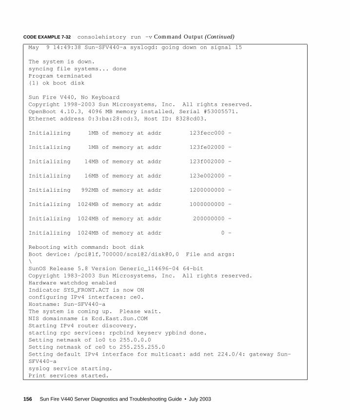
May 9 14:49:38 Sun-SFV440-a syslogd: going down on signal 15
The system is down.syncing file systems... doneProgram terminated{1} ok boot disk
Sun Fire V440, No KeyboardCopyright 1998-2003 Sun Microsystems, Inc. All rights reserved.OpenBoot 4.10.3, 4096 MB memory installed, Serial #53005571.Ethernet address 0:3:ba:28:cd:3, Host ID: 8328cd03.
Initializing 1MB of memory at addr 123fecc000 -
Initializing 1MB of memory at addr 123fe02000 -
Initializing 14MB of memory at addr 123f002000 -
Initializing 16MB of memory at addr 123e002000 -
Initializing 992MB of memory at addr 1200000000 -
Initializing 1024MB of memory at addr 1000000000 -
Initializing 1024MB of memory at addr 200000000 -
Initializing 1024MB of memory at addr 0 -
Rebooting with command: boot diskBoot device: /pci@1f,700000/scsi@2/disk@0,0 File and args:\SunOS Release 5.8 Version Generic_114696-04 64-bitCopyright 1983-2003 Sun Microsystems, Inc. All rights reserved.Hardware watchdog enabledIndicator SYS_FRONT.ACT is now ONconfiguring IPv4 interfaces: ce0.Hostname: Sun-SFV440-aThe system is coming up. Please wait.NIS domainname is Ecd.East.Sun.COMStarting IPv4 router discovery.starting rpc services: rpcbind keyserv ypbind done.Setting netmask of lo0 to 255.0.0.0Setting netmask of ce0 to 255.255.255.0Setting default IPv4 interface for multicast: add net 224.0/4: gateway Sun-SFV440-asyslog service starting.Print services started.
CODE EXAMPLE 7-32 consolehistory run -v Command Output (Continued)
156 Sun Fire V440 Server Diagnostics and Troubleshooting Guide • July 2003
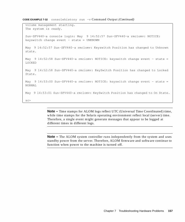
Note – Time stamps for ALOM logs reflect UTC (Universal Time Coordinated) time,
while time stamps for the Solaris operating environment reflect local (server) time.
Therefore, a single event might generate messages that appear to be logged at
different times in different logs.
Note – The ALOM system controller runs independently from the system and uses
standby power from the server. Therefore, ALOM firmware and software continue to
function when power to the machine is turned off.
volume management starting.The system is ready.
Sun-SFV440-a console login: May 9 14:52:57 Sun-SFV440-a rmclomv: NOTICE:keyswitch change event - state = UNKNOWN
May 9 14:52:57 Sun-SFV440-a rmclomv: Keyswitch Position has changed to Unknownstate.
May 9 14:52:58 Sun-SFV440-a rmclomv: NOTICE: keyswitch change event - state =LOCKED
May 9 14:52:58 Sun-SFV440-a rmclomv: KeySwitch Position has changed to LockedState.
May 9 14:53:00 Sun-SFV440-a rmclomv: NOTICE: keyswitch change event - state =NORMAL
May 9 14:53:01 Sun-SFV440-a rmclomv: KeySwitch Position has changed to On State.
sc>
CODE EXAMPLE 7-32 consolehistory run -v Command Output (Continued)
Chapter 7 Troubleshooting Hardware Problems 157
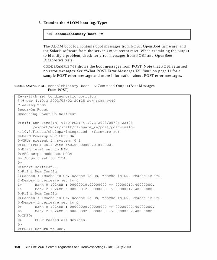
3. Examine the ALOM boot log. Type:
The ALOM boot log contains boot messages from POST, OpenBoot firmware, and
the Solaris software from the server’s most recent reset. When examining the output
to identify a problem, check for error messages from POST and OpenBoot
Diagnostics tests.
CODE EXAMPLE 7-33 shows the boot messages from POST. Note that POST returned
no error messages. See “What POST Error Messages Tell You” on page 11 for a
sample POST error message and more information about POST error messages.
sc> consolehistory boot -v
CODE EXAMPLE 7-33 consolehistory boot -v Command Output (Boot MessagesFrom POST)
Keyswitch set to diagnostic position.@(#)OBP 4.10.3 2003/05/02 20:25 Sun Fire V440Clearing TLBsPower-On ResetExecuting Power On SelfTest
0>@(#) Sun Fire[TM] V440 POST 4.10.3 2003/05/04 22:08 /export/work/staff/firmware_re/post/post-build-4.10.3/Fiesta/chalupa/integrated (firmware_re)0>Hard Powerup RST thru SW0>CPUs present in system: 0 10>OBP->POST Call with %o0=00000000.01012000.0>Diag level set to MIN.0>MFG scrpt mode set NORM0>I/O port set to TTYA.0>0>Start selftest...1>Print Mem Config1>Caches : Icache is ON, Dcache is ON, Wcache is ON, Pcache is ON.1>Memory interleave set to 01> Bank 0 1024MB : 00000010.00000000 -> 00000010.40000000.1> Bank 2 1024MB : 00000012.00000000 -> 00000012.40000000.0>Print Mem Config0>Caches : Icache is ON, Dcache is ON, Wcache is ON, Pcache is ON.0>Memory interleave set to 00> Bank 0 1024MB : 00000000.00000000 -> 00000000.40000000.0> Bank 2 1024MB : 00000002.00000000 -> 00000002.40000000.0>INFO:0> POST Passed all devices.0>0>POST: Return to OBP.
158 Sun Fire V440 Server Diagnostics and Troubleshooting Guide • July 2003
4. Turn the system control keyswitch to the Diagnostics position.
5. Power on the system.
If the system does not boot, the system might have a basic hardware problem. If you
have not made any recent hardware changes to the system, contact your authorized
service provider.
6. If the system gets to the ok prompt but does not load the operating environment,you might need to change the boot-device setting in the system firmware.
See “How to Use OpenBoot Information Commands” on page 94 for information
about using the probe commands. You can use the probe commands to display
information about active SCSI and IDE devices.
For information on changing the default boot device, see the Solaris SystemAdministration Guide: Basic Administration.
a. Try to load the operating environment for a single user from a CD.
Place a valid Solaris operating environment CD into the system DVD–ROM or
CD–ROM drive and enter boot cdrom -s from the ok prompt.
b. If the system boots from the CD and loads the operating environment, checkthe following:
■ If the system normally boots from a system hard disk, check the system disk for
problems and a valid boot image.
■ If the system normally boots from the network, check the system network
configuration, the system Ethernet cables, and the system network card.
c. If the system gets to the ok prompt but does not load the operatingenvironment from the CD, check the following:
■ OpenBoot variable settings (boot-device , diag-device , and auto-boot? ).
■ OpenBoot PROM device tree. See “show-devs Command” on page 23 for more
information.
■ That the banner was displayed before the ok prompt.
■ Any diagnostic test failure or other hardware failure message before the okprompt was displayed.
Chapter 7 Troubleshooting Hardware Problems 159
How to Troubleshoot a System That IsHanging
Before You Begin
This procedure assumes that the system console is in its default configuration, so
that you are able to switch between the system controller and the system console.
See:
■ “About Communicating With the System” on page 164
■ “Access Through the Network Management Port” on page 168
What to Do
1. Verify that the system is hanging.
a. Type the ping command to determine whether there is any network activity.
b. Type the ps -ef command to determine whether any other user sessions areactive or responding.
If another user session is active, use it to review the contents of the
/var/adm/messages file for any indications of the system problem.
c. Try to access the system console through the ALOM system controller.
If you can establish a working system console connection, the problem might not
be a true hang but might instead be a network-related problem. For suspected
network problems, use the ping , rlogin , or telnet commands to reach another
system that is on the same sub-network, hub, or router. If NFS services are served
by the affected system, determine whether NFS activity is present on other
systems.
d. Change the system control keyswitch position while observing the systemconsole.
For example, turn the keyswitch from the Normal position to the Diagnostics
position, or from the Locked position to the Normal position. If the system
console logs the change of keyswitch position, the system is not fully hung.
160 Sun Fire V440 Server Diagnostics and Troubleshooting Guide • July 2003
2. If there are no responding user sessions, record the state of the system LEDs.
The system LEDs might indicate a hardware failure in the system. You can use the
ALOM system controller to check the state of the system LEDs. Refer to the
Sun Fire V440 Server Administration Guide for more information about system LEDs.
3. Attempt to bring the system to the ok prompt.
For instructions, see “How to Get to the ok Prompt” on page 176.
If the system can get to the ok prompt, then the system hang can be classified as a
soft hang. Otherwise, the system hang can be classified as a hard hang. See
“Responding to System Hang States” on page 123 for more information.
4. If the preceding step failed to bring the system to the ok prompt, execute anexternally initiated reset (XIR).
Executing an XIR resets the system and preserves the state of the system before it
resets, so that indications and messages about transient errors might be saved.
An XIR is the equivalent of issuing a direct hardware reset. For further information
about XIR, see “Externally Initiated Reset (XIR)” on page 173.
5. If an XIR brings the system to the ok prompt, do the following.
a. Issue the printenv command.
This command displays the settings of the OpenBoot configuration variables.
b. Set the auto-boot ? variable to true , the diag-switch? variable to true , thediag-level variable to max, and the post-trigger and obdiag-triggervariables to all-resets .
c. Issue the sync command to obtain a core dump file.
Core dump files provide invaluable information to your support provider to aid
in diagnosing any system problems. For further information about core dump
files, see “About the Core Dump Process” on page 113 and “Managing System
Crash Information” in the Solaris System Administration Guide, which is part of the
Solaris System Administrator Collection.
The system reboots automatically provided that the OpenBoot configuration
auto-boot ? variable is set to true (default value).
Note – Steps 3, 4, and 5 occur automatically when the hardware watchdog
mechanism is enabled.
6. If an XIR failed to bring the system to the ok prompt, follow these steps:
a. Turn the system control keyswitch to the Diagnostics position.
This forces the system to run POST and OpenBoot Diagnostics tests during
system startup.
Chapter 7 Troubleshooting Hardware Problems 161

b. Press the system Power button for five seconds.
This causes an immediate hardware shutdown.
c. Wait at least 30 seconds; then power on the system by pressing the Powerbutton.
Note – You can also use the ALOM system controller to set the POST and OpenBoot
Diagnostics levels, and to power off and reboot the system. See the Sun AdvancedLights Out Manager (ALOM) Online Help.
7. Use the POST and OpenBoot Diagnostics tests to diagnose system problems.
When the system initiates the startup sequence, it will run POST and OpenBoot
Diagnostics tests. See “How to Isolate Faults Using POST Diagnostics” on page 65
and “How to Isolate Faults Using Interactive OpenBoot Diagnostics Tests” on
page 67.
8. Review the contents of the /var/adm/messages file.
Look for the following information about the system’s state:
■ Any large gaps in the time stamp of Solaris software or application messages
■ Warning messages about any hardware or software components
■ Information from last root logins to determine whether any system administrators
might be able to provide any information about the system state at the time of the
hang
9. If possible, check whether the system saved a core dump file.
Core dump files provide invaluable information to your support provider to aid in
diagnosing any system problems. For further information about core dump files, see
“About the Core Dump Process” on page 113 and “Managing System Crash
Information” in the Solaris System Administration Guide, which is part of the Solaris
System Administrator Collection.
162 Sun Fire V440 Server Diagnostics and Troubleshooting Guide • July 2003
APPENDIX A
Configuring the System Console
This appendix explains what the system console is, describes the different ways of
configuring it on a Sun Fire V440 server, and helps you to understand its relation to
the system controller.
Tasks covered in this chapter include:
■ “How to Get to the ok Prompt” on page 176
■ “How to Use the Serial Management Port” on page 178
■ “How to Activate the Network Management Port” on page 179
■ “How to Access the System Console via a Terminal Server” on page 181
■ “How to Access the System Console via tip Connection” on page 184
■ “How to Modify the /etc/remote File” on page 187
■ “How to Verify Serial Port Settings on ttyb ” on page 191
■ “How to Access the System Console via an Alphanumeric Terminal” on page 189
■ “How to Access the System Console via a Local Graphics Monitor” on page 192
Other information in this appendix includes:
■ “About Communicating With the System” on page 164
■ “About the sc> Prompt” on page 169
■ “About the ok Prompt” on page 171
■ “About Switching Between the ALOM System Controller and the System
Console” on page 175
■ “Reference for System Console OpenBoot Configuration Variable Settings” on
page 196
163
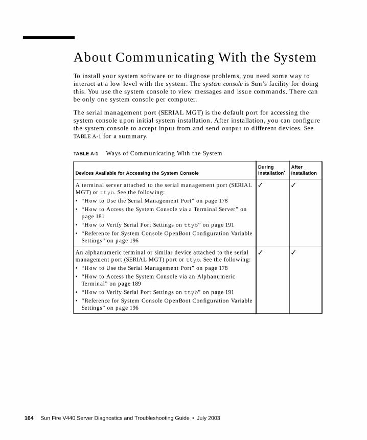
About Communicating With the System
To install your system software or to diagnose problems, you need some way to
interact at a low level with the system. The system console is Sun’s facility for doing
this. You use the system console to view messages and issue commands. There can
be only one system console per computer.
The serial management port (SERIAL MGT) is the default port for accessing the
system console upon initial system installation. After installation, you can configure
the system console to accept input from and send output to different devices. See
TABLE A-1 for a summary.
TABLE A-1 Ways of Communicating With the System
Devices Available for Accessing the System ConsoleDuringInstallation *
AfterInstallation
A terminal server attached to the serial management port (SERIAL
MGT) or ttyb . See the following:
• “How to Use the Serial Management Port” on page 178
• “How to Access the System Console via a Terminal Server” on
page 181
• “How to Verify Serial Port Settings on ttyb ” on page 191
• “Reference for System Console OpenBoot Configuration Variable
Settings” on page 196
✓ ✓
An alphanumeric terminal or similar device attached to the serial
management port (SERIAL MGT) port or ttyb . See the following:
• “How to Use the Serial Management Port” on page 178
• “How to Access the System Console via an Alphanumeric
Terminal” on page 189
• “How to Verify Serial Port Settings on ttyb ” on page 191
• “Reference for System Console OpenBoot Configuration Variable
Settings” on page 196
✓ ✓
164 Sun Fire V440 Server Diagnostics and Troubleshooting Guide • July 2003
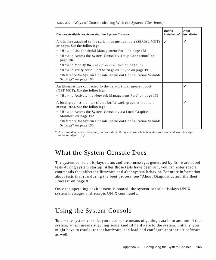
What the System Console Does
The system console displays status and error messages generated by firmware-based
tests during system startup. After those tests have been run, you can enter special
commands that affect the firmware and alter system behavior. For more information
about tests that run during the boot process, see “About Diagnostics and the Boot
Process” on page 8.
Once the operating environment is booted, the system console displays UNIX
system messages and accepts UNIX commands.
Using the System Console
To use the system console, you need some means of getting data in to and out of the
system, which means attaching some kind of hardware to the system. Initially, you
might have to configure that hardware, and load and configure appropriate software
as well.
A tip line attached to the serial management port (SERIAL MGT)
or ttyb . See the following:
• “How to Use the Serial Management Port” on page 178
• “How to Access the System Console via tip Connection” on
page 184
• “How to Modify the /etc/remote File” on page 187
• “How to Verify Serial Port Settings on ttyb ” on page 191
• “Reference for System Console OpenBoot Configuration Variable
Settings” on page 196
✓ ✓
An Ethernet line connected to the network management port
(NET MGT). See the following:
• “How to Activate the Network Management Port” on page 179
✓
A local graphics monitor (frame buffer card, graphics monitor,
mouse, etc.). See the following:
• “How to Access the System Console via a Local Graphics
Monitor” on page 192
• “Reference for System Console OpenBoot Configuration Variable
Settings” on page 196.
✓
* After initial system installation, you can redirect the system console to take its input from and send its outputto the serial port ttyb .
TABLE A-1 Ways of Communicating With the System (Continued)
Devices Available for Accessing the System ConsoleDuringInstallation *
AfterInstallation
Appendix A Configuring the System Console 165
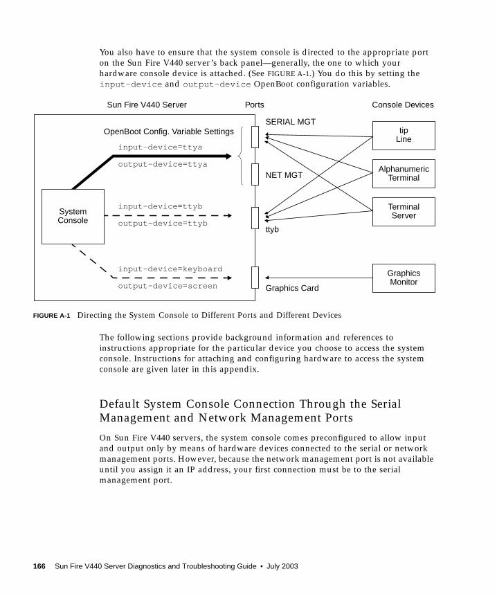
You also have to ensure that the system console is directed to the appropriate port
on the Sun Fire V440 server’s back panel—generally, the one to which your
hardware console device is attached. (See FIGURE A-1.) You do this by setting the
input-device and output-device OpenBoot configuration variables.
FIGURE A-1 Directing the System Console to Different Ports and Different Devices
The following sections provide background information and references to
instructions appropriate for the particular device you choose to access the system
console. Instructions for attaching and configuring hardware to access the system
console are given later in this appendix.
Default System Console Connection Through the SerialManagement and Network Management Ports
On Sun Fire V440 servers, the system console comes preconfigured to allow input
and output only by means of hardware devices connected to the serial or network
management ports. However, because the network management port is not available
until you assign it an IP address, your first connection must be to the serial
management port.
Graphics Card
ttyb
NET MGT
SERIAL MGT
Sun Fire V440 Server
ServerTerminal
TerminalAlphanumeric
Linetip
MonitorGraphics
ConsoleSystem
input-device =keyboard
output-device =screen
input-device =ttyb
output-device =ttyb
input-device =ttya
output-device =ttya
Ports Console Devices
OpenBoot Config. Variable Settings
166 Sun Fire V440 Server Diagnostics and Troubleshooting Guide • July 2003
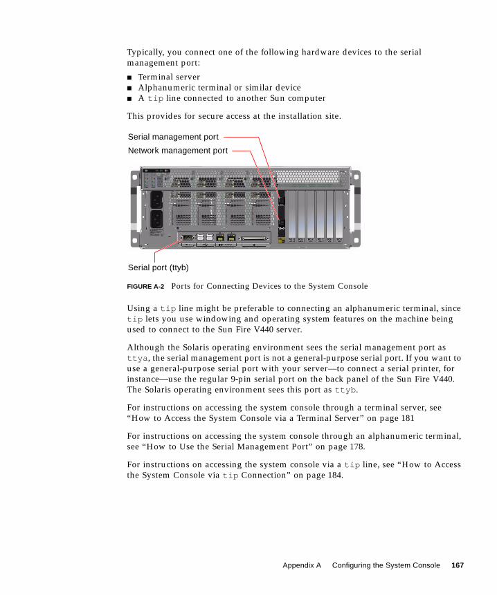
Typically, you connect one of the following hardware devices to the serial
management port:
■ Terminal server
■ Alphanumeric terminal or similar device
■ A tip line connected to another Sun computer
This provides for secure access at the installation site.
FIGURE A-2 Ports for Connecting Devices to the System Console
Using a tip line might be preferable to connecting an alphanumeric terminal, since
tip lets you use windowing and operating system features on the machine being
used to connect to the Sun Fire V440 server.
Although the Solaris operating environment sees the serial management port as
ttya , the serial management port is not a general-purpose serial port. If you want to
use a general-purpose serial port with your server—to connect a serial printer, for
instance—use the regular 9-pin serial port on the back panel of the Sun Fire V440.
The Solaris operating environment sees this port as ttyb .
For instructions on accessing the system console through a terminal server, see
“How to Access the System Console via a Terminal Server” on page 181
For instructions on accessing the system console through an alphanumeric terminal,
see “How to Use the Serial Management Port” on page 178.
For instructions on accessing the system console via a tip line, see “How to Access
the System Console via tip Connection” on page 184.
Serial management port
Network management port
Serial port (ttyb)
Appendix A Configuring the System Console 167

Access Through the Network Management Port
Once you have assigned an IP address to the network management port, you can
connect an Ethernet-capable device and access the system console through your
network. This provides for remote monitoring and control. In addition, up to four
simultaneous connections to the system controller sc> prompt are available through
the network management port. For instructions on setting up the network
management port, see “How to Activate the Network Management Port” on
page 179.
For more information about the system console and the ALOM system controller,
see:
■ “About the sc> Prompt” on page 169
■ “About the ok Prompt” on page 171
Alternative System Console Configuration
In the default configuration, system controller alerts and system console output
appear interspersed in the same window. After initial system installation, you can
redirect the system console to take its input from and send its output to the serial
port ttyb or to a graphics card’s port.
The chief advantage of setting up the system console in this way is that it allows you
to divide system controller alerts and system console output into two separate
windows.
However, there are some serious disadvantages to alternative console configuration:
■ POST output can only be directed to the serial and network management ports. It
cannot be directed to ttyb or to a graphics card’s port.
■ If you have directed the system console to ttyb , you cannot use this port for any
other serial device.
■ In a default configuration, the serial and network management ports allow you to
open up to four additional windows by which you can view, but not affect,
system console activity. You cannot open these windows if the system console is
redirected to ttyb or to a graphics card’s port.
■ In a default configuration, the serial and network management ports allow you to
switch between viewing system console and system controller output on the same
device by typing a simple escape sequence or commands. The escape sequence
and commands will not work if the system console is redirected to ttyb or to a
graphic card’s port.
■ The system controller keeps a log of console messages, but some messages are not
logged if the system console is redirected to ttyb or to a graphic card’s port. The
omitted information could be important if you need to contact Sun customer
service with a problem.
168 Sun Fire V440 Server Diagnostics and Troubleshooting Guide • July 2003
For all the preceding reasons, the best practice is to leave the system console in its
default configuration.
You change the system console configuration by setting OpenBoot configuration
variables. See “Reference for System Console OpenBoot Configuration Variable
Settings” on page 196.
You can also set OpenBoot configuration variables using the ALOM system
controller. For details, see the Advanced Lights Out Manager (ALOM) Online Help.
Accessing the System Console Through a Graphics Monitor
The Sun Fire V440 server is shipped without a mouse, keyboard, monitor, or frame
buffer for the display of bitmapped graphics. To install a graphics monitor on the
server, you must install a frame buffer card into a PCI slot, and attach a monitor,
mouse, and keyboard to the appropriate back panel ports.
After starting the system, you might need to install the correct software driver for
the PCI card you have installed. For detailed hardware instructions, see “How to
Access the System Console via a Local Graphics Monitor” on page 192.
Note – Power-on self-test (POST) diagnostics cannot display status and error
messages to a local graphics monitor.
About the sc> Prompt
The ALOM system controller runs independently of the Sun Fire V440 server and
regardless of system power state. When you connect a Sun Fire V440 server to AC
power, the ALOM system controller immediately starts up, and begins monitoring
the system.
Note – To view ALOM system controller boot messages, you must connect an
alphanumeric terminal to the serial management port before connecting the AC
power cords to the Sun Fire V440 server.
You can log in to the ALOM system controller at any time, regardless of system
power state, as long as AC power is connected to the system and you have a way of
interacting with the system. You can also access the ALOM system controller prompt
Appendix A Configuring the System Console 169
(sc> ) from the ok prompt or from the Solaris prompt, provided the system console
is configured to be accessible through the serial and network management ports. For
more information, see the following:
■ “How to Get to the ok Prompt” on page 176
■ “About Switching Between the ALOM System Controller and the System
Console” on page 175
The sc> prompt indicates that you are interacting with the ALOM system controller
directly. It is the first prompt you see when you log in to the system through the
serial management port or network management port, regardless of system power
state.
Note – When you access the ALOM system controller for the first time, it forces you
to create a user name and password for subsequent access. After this initial
configuration, you will be prompted to enter a user name and password every time
you access the ALOM system controller.
Access Through Multiple Controller Sessions
Up to five ALOM system controller sessions can be active concurrently, one session
through the serial management port and up to four sessions through the network
management port. Users of each of these sessions can issue commands at the sc>prompt, but only one user at a time can access the system console, and then only if
the system console is configured to be accessible through the serial and network
management ports. For more information, see
■ “How to Use the Serial Management Port” on page 178
■ “How to Activate the Network Management Port” on page 179
Any additional ALOM system controller sessions afford passive views of system
console activity, until the active user of the system console logs out. However, the
console -f command, if you enable it, allows users to seize access to the system
console from one another. For more information, see the Sun Advanced Lights OutManager (ALOM) Online Help.
Ways of Reaching the sc> Prompt
There are several ways to get to the sc> prompt. These are:
■ If the system console is directed to the serial and network management ports, you
can type the ALOM system controller escape sequence (#. ).
170 Sun Fire V440 Server Diagnostics and Troubleshooting Guide • July 2003
■ You can log in directly to the ALOM system controller from a device connected to
the serial management port. See “How to Use the Serial Management Port” on
page 178.
■ You can log in directly to the ALOM system controller using a connection through
the network management port. See “How to Activate the Network Management
Port” on page 179.
About the ok Prompt
A Sun Fire V440 server with the Solaris operating environment installed is capable
of operating at different run levels. A synopsis of run levels follows. For a full
description, see the Solaris system administration documentation.
Most of the time, you operate a Sun Fire V440 server at run level 2 or run level 3,
which are multiuser states with access to full system and network resources.
Occasionally, you might operate the system at run level 1, which is a single-user
administrative state. However, the lowest operational state is run level 0. At this
state, it is safe to turn off power to the system.
When a Sun Fire V440 system is at run level 0, the ok prompt appears. This prompt
indicates that the OpenBoot firmware is in control of the system.
There are a number of scenarios in which OpenBoot firmware control can happen.
■ By default, the system comes up under OpenBoot firmware control before the
operating environment is installed.
■ The system boots to the ok prompt when the auto-boot? OpenBoot
configuration variable is set to false .
■ The system transitions to run level 0 in an orderly way when the operating
environment is halted.
■ The system reverts to OpenBoot firmware control when the operating
environment crashes.
■ During the boot process, when there is a serious hardware problem that prevents
the operating environment from running, the system reverts to OpenBoot
firmware control.
■ When a serious hardware problem develops while the system is running, the
operating environment transitions smoothly to run level 0.
■ You deliberately place the system under firmware control in order to execute
firmware-based commands or to run diagnostic tests.
Appendix A Configuring the System Console 171
It is the last of these scenarios that most often concerns you as an administrator,
since there will be times when you need to reach the ok prompt. The several ways to
do this are outlined in “Ways of Reaching the ok Prompt” on page 172. For detailed
instructions, see “How to Get to the ok Prompt” on page 176.
Ways of Reaching the ok Prompt
There are several ways to get to the ok prompt, depending on the state of the system
and the means by which you are accessing the system console. In order of
desirability, these are:
■ Graceful shutdown of the Solaris operating environment
■ ALOM system controller break or console command
■ L1-A (Stop-A) keys or Break key
■ Externally initiated reset (XIR)
■ Manual system reset
A discussion of each method follows. For instructions, see “How to Get to the okPrompt” on page 176.
Graceful Shutdown
The preferred method of reaching the ok prompt is to shut down the operating
environment by issuing an appropriate command (for example, the shutdown ,
init , or uadmin command) as described in Solaris system administration
documentation. You can also use the system Power button to initiate a graceful
system shutdown.
Gracefully shutting down the system prevents data loss, enables you to warn users
beforehand, and causes minimal disruption. You can usually perform a graceful
shutdown, provided the Solaris operating environment is running and the hardware
has not experienced serious failure.
You can also perform a graceful system shutdown from the ALOM system controller
command prompt.
For more information, see the Sun Fire V440 Server Administration Guide.
ALOM System Controller break or console Command
Typing break from the sc> prompt forces a running Sun Fire V440 system to drop
into OpenBoot firmware control. If the operating system is already shut down, you
can use the console command instead of break to reach the ok prompt.
172 Sun Fire V440 Server Diagnostics and Troubleshooting Guide • July 2003

After forcing the system into OpenBoot firmware control, be aware that issuing
certain OpenBoot commands (like probe-scsi , probe-scsi-all , or probe-ide )
might hang the system.
L1-A (Stop-A) Keys or Break Key
When it is impossible or impractical to shut down the system gracefully, you can get
to the ok prompt by typing the L1-A (Stop-A) key sequence from a Sun keyboard, or,
if you have an alphanumeric terminal attached to the Sun Fire V440 server, by
pressing the Break key.
Note – These methods of reaching the ok prompt will only work if the system
console has been redirected to the appropriate port. For details, see “Reference for
System Console OpenBoot Configuration Variable Settings” on page 196.
If you use these methods to reach the ok prompt, be aware that issuing certain
OpenBoot commands (like probe-scsi , probe-scsi-all , or probe-ide ) might
hang the system.
Externally Initiated Reset (XIR)
Use the ALOM system controller reset -x command to execute an externally
initiated reset (XIR). Forcing an XIR might be effective in breaking the deadlock that
is hanging up the system. However, an XIR also precludes the orderly shutdown of
applications, and so it is not the preferred method of reaching the ok prompt, unless
you are troubleshooting these types of system hangs. Generating an XIR has the
advantage of allowing you to issue the sync command to produce a dump file of the
current system state for diagnostic purposes.
For more information about the reset -x command, see the Sun Advanced LightsOut Manager (ALOM) Online Help.
Caution – Because an XIR precludes an orderly shutdown of applications, it should
only be attempted if previously described methods do not work.
Manual System Reset
Use the ALOM system controller reset command or poweroff and poweroncommands to reset the server. Reaching the ok prompt by performing a manual
system reset or by power-cycling the system should be the method of last resort.
Appendix A Configuring the System Console 173

Doing this results in the loss of all system coherence and state information. A
manual system reset could corrupt the server’s file systems, although the fsckcommand usually restores them. Use this method only when nothing else works.
Caution – Forcing a manual system reset results in loss of system state data and
should be attempted only as a last resort. After a manual system reset, all state
information is lost, which inhibits troubleshooting the cause of the problem until the
problem reoccurs.
Important: Accessing the ok Prompt Suspends the
Solaris Operating Environment
It is important to understand that when you access the ok prompt from a
functioning Sun Fire V440 server, you are suspending the Solaris operating
environment and placing the system under firmware control. Any processes that
were running under the operating environment are also suspended, and the state ofsuch processes might not be recoverable.
The diagnostic tests and commands you run from the ok prompt have the potential
to affect the state of the system. This means that it is not always possible to resume
execution of the operating environment from the point at which it was suspended.
Although the go command will resume execution in most circumstances, in general,
each time you drop the system down to the ok prompt, you should expect to have to
reboot the system to get back to the operating environment.
As a rule, before suspending the operating environment, you should back up files,
warn users of the impending shutdown, and shut down the system in an orderly
manner. However, it is not always possible to take such precautions, especially if the
system is malfunctioning.
For More Information
For more information about the OpenBoot firmware, see the OpenBoot 4.x CommandReference Manual. An online version of the manual is included with the OpenBootCollection AnswerBook that ships with Solaris software.
174 Sun Fire V440 Server Diagnostics and Troubleshooting Guide • July 2003
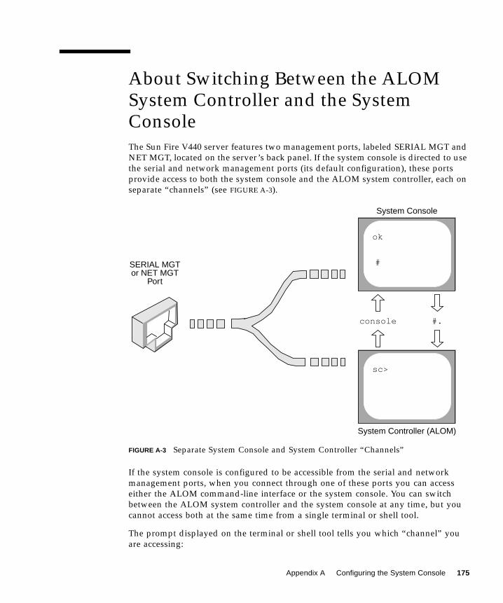
About Switching Between the ALOMSystem Controller and the SystemConsole
The Sun Fire V440 server features two management ports, labeled SERIAL MGT and
NET MGT, located on the server’s back panel. If the system console is directed to use
the serial and network management ports (its default configuration), these ports
provide access to both the system console and the ALOM system controller, each on
separate “channels” (see FIGURE A-3).
FIGURE A-3 Separate System Console and System Controller “Channels”
If the system console is configured to be accessible from the serial and network
management ports, when you connect through one of these ports you can access
either the ALOM command-line interface or the system console. You can switch
between the ALOM system controller and the system console at any time, but you
cannot access both at the same time from a single terminal or shell tool.
The prompt displayed on the terminal or shell tool tells you which “channel” you
are accessing:
SERIAL MGTor NET MGT
Port
ok
sc>
#
System Console
System Controller (ALOM)
console #.
Appendix A Configuring the System Console 175

■ The # or %prompt indicates that you are at the system console and that the
Solaris operating environment is running.
■ The ok prompt indicates that you are at the system console and that the server is
running under OpenBoot firmware control.
■ The sc> prompt indicates you are at the ALOM system controller.
Note – If no text or prompt appears, it may be the case that no console messages
were recently generated by the system. If this happens, pressing the terminal’s Enter
or Return key should produce a prompt.
To reach the system console from the ALOM system controller, type the consolecommand at the sc> prompt. To reach the ALOM system controller from the system
console, type the system controller escape sequence, which by default is #. (pound
period).
For more information, see the following:
■ “About Communicating With the System” on page 164
■ “About the sc> Prompt” on page 169
■ “About the ok Prompt” on page 171
■ “How to Use the Serial Management Port” on page 178
■ Sun Advanced Lights Out Manager (ALOM) Online Help
How to Get to the ok Prompt
Before You Begin
This procedure provides several ways of reaching the ok prompt. The methods are
not equally desirable. For details about when to use each method, see:
■ “About the ok Prompt” on page 171
Note – Dropping the Sun Fire V440 server to the ok prompt suspends all
application and operating system software. After you issue firmware commands and
run firmware-based tests from the ok prompt, the system might not be able to
resume where it left off.
176 Sun Fire V440 Server Diagnostics and Troubleshooting Guide • July 2003
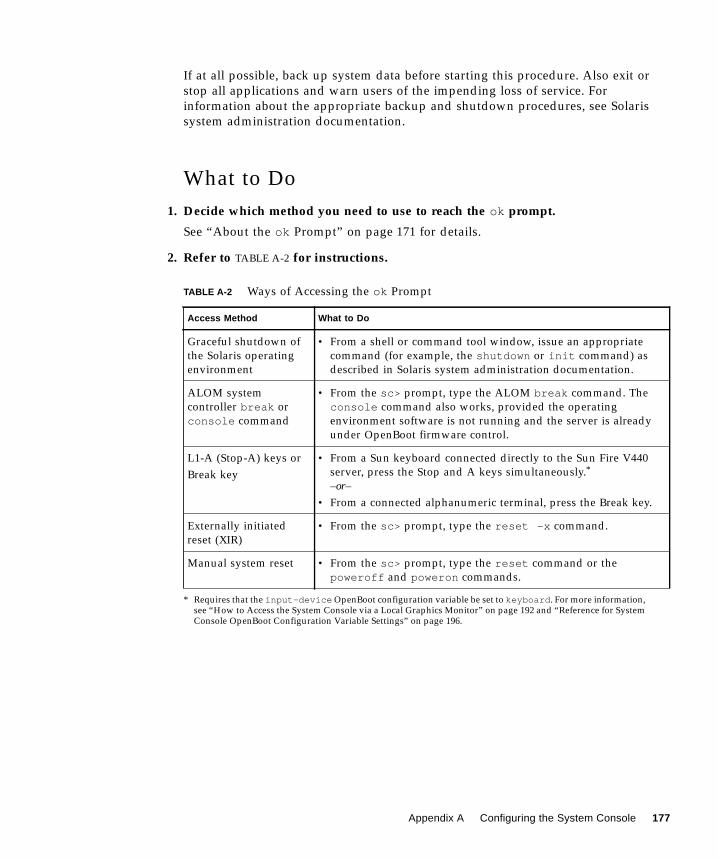
If at all possible, back up system data before starting this procedure. Also exit or
stop all applications and warn users of the impending loss of service. For
information about the appropriate backup and shutdown procedures, see Solaris
system administration documentation.
What to Do
1. Decide which method you need to use to reach the ok prompt.
See “About the ok Prompt” on page 171 for details.
2. Refer to TABLE A-2 for instructions.
TABLE A-2 Ways of Accessing the ok Prompt
Access Method What to Do
Graceful shutdown of
the Solaris operating
environment
• From a shell or command tool window, issue an appropriate
command (for example, the shutdown or init command) as
described in Solaris system administration documentation.
ALOM system
controller break or
console command
• From the sc> prompt, type the ALOM break command. The
console command also works, provided the operating
environment software is not running and the server is already
under OpenBoot firmware control.
L1-A (Stop-A) keys or
Break key
• From a Sun keyboard connected directly to the Sun Fire V440
server, press the Stop and A keys simultaneously.*
–or–• From a connected alphanumeric terminal, press the Break key.
* Requires that the input-device OpenBoot configuration variable be set to keyboard . For more information,see “How to Access the System Console via a Local Graphics Monitor” on page 192 and “Reference for SystemConsole OpenBoot Configuration Variable Settings” on page 196.
Externally initiated
reset (XIR)
• From the sc> prompt, type the reset -x command.
Manual system reset • From the sc> prompt, type the reset command or the
poweroff and poweron commands.
Appendix A Configuring the System Console 177
How to Use the Serial Management Port
This procedure assumes that the system console is directed to use the serial
management and network management ports (the default configuration).
When you are accessing the system console using a device connected to the serial
management port, your first point of access is the ALOM system controller and its
sc> prompt. After connecting to the ALOM system controller, you can switch to the
system console itself.
For more information about the ALOM system controller, see:
■ “Monitoring the System Using Sun Advanced Lights Out Manager” on page 35
■ “How to Monitor the System Using Sun Advanced Lights Out Manager” on
page 79
■ Sun Advanced Lights Out Manager (ALOM) Online Help
Before You Begin
Make sure that your connecting device is set to the following parameters:
■ 9600 baud
■ 8 bits
■ No parity
■ 1 stop bit
■ No handshaking
What to Do
1. Establish an ALOM system controller session.
See Sun Advanced Lights Out Manager (ALOM) Online Help for instructions.
2. At the ALOM system controller prompt, type:
The console command switches you to the system console.
sc> console
178 Sun Fire V440 Server Diagnostics and Troubleshooting Guide • July 2003
3. To switch back to the sc> prompt, type the #. escape sequence.
What Next
For instructions on how to use the ALOM system controller, see:
■ Sun Advanced Lights Out Manager (ALOM) Online Help
How to Activate the NetworkManagement Port
Before You Begin
You must assign an Internet Protocol (IP) address to the network management port
before you can use it. If you are configuring the network management port for the
first time, you must first connect to the ALOM system controller using the serial
management port and assign an IP address to the network management port. You
can either assign an IP address manually, or you can configure the port to obtain an
IP address using the Dynamic Host Configuration Protocol (DHCP) from another
server.
Note – The IP address assigned to the network management port is a unique IP
address, separate from the main Sun Fire V440 server IP address.
Data centers frequently devote a separate subnet to system management. If your
data center has such a configuration, connect the network management port to this
subnet.
Note – The network management port is a 10BASE-T port and is dedicated for use
only with the ALOM system controller. The network management port does not
support connections to 100-Mbps or 1-Gbps networks.
ok #. [characters are not echoed to the screen]
Appendix A Configuring the System Console 179
What to Do
1. Connect an Ethernet cable to the network management port.
2. Log in to the ALOM system controller through the serial management port.
For more information about connecting to the serial management port, see “How to
Use the Serial Management Port” on page 178.
3. Type one of the following commands:
■ If your network uses static IP addresses, type:
You can also use the setupsc command.
■ If your network uses Dynamic Host Configuration Protocol (DHCP), type:
4. To verify the network settings, type:
5. Log out of the ALOM system controller session.
What Next
To connect to the system console through the network management port, use the
telnet command to the IP address you specified in Step 3 of the preceding
procedure.
sc> setsc if_network truesc> setsc netsc_ipaddr ip-addresssc> setsc netsc_ipnetmask ip-addresssc> setsc netsc_ipgateway ip-address
sc> setsc netsc_dhcp
sc> shownetwork
180 Sun Fire V440 Server Diagnostics and Troubleshooting Guide • July 2003
How to Access the System Console via aTerminal Server
Before You Begin
The following procedure assumes that you are accessing the Sun Fire V440 server
system console by connecting a terminal server to the serial management port
(SERIAL MGT) of the Sun Fire V440 server.
What to Do
1. Complete the physical connection from the serial management port to yourterminal server.
The serial management port on the Sun Fire V440 server is a data terminal
equipment (DTE) port. The pinouts for the serial management port correspond with
the pinouts for the RJ-45 ports on the Serial Interface Breakout Cable supplied by
Cisco for use with the Cisco AS2511-RJ terminal server. If you use a terminal server
made by another manufacturer, check that the serial port pinouts of the Sun Fire
V440 server match those of the terminal server you plan to use.
If the pinouts for the server serial ports correspond with the pinouts for the RJ-45
ports on the terminal server, you have two connection options:
■ Connect a serial interface breakout cable directly to the Sun Fire V440 server. See
“How to Use the Serial Management Port” on page 178.
■ Connect a serial interface breakout cable to a patch panel and use the straight-
through patch cable (supplied by Sun) to connect the patch panel to the server.
Appendix A Configuring the System Console 181

FIGURE A-4 Patch Panel Connection Between a Terminal Server and a Sun Fire V440Server
If the pinouts for the serial management port do not correspond with the pinouts for
the RJ-45 ports on the terminal server, you need to make a crossover cable that takes
each pin on the Sun Fire V440 server serial port to the corresponding pin in the
terminal server’s serial port.
TABLE A-3 shows the crossovers that the cable must perform.
TABLE A-3 Pin Crossovers for Connecting to a Typical Terminal Server
Sun Fire V440 Serial Port (RJ-45 Connector) Pin Terminal Server Serial Port Pin
Pin 1 (RTS) Pin 1 (CTS)
Pin 2 (DTR) Pin 2 (DSR)
Pin 3 (TXD) Pin 3 (RXD)
Pin 4 (Signal Ground) Pin 4 (Signal Ground)
Pin 5 (Signal Ground) Pin 5 (Signal Ground)
Pin 6 (RXD) Pin 6 (TXD)
Pin 7 (DSR /DCD) Pin 7 (DTR)
Pin 8 (CTS) Pin 8 (RTS)
1 2 3 4 5 6 7 8 9 10 11 12 13 14 15
1 2 3 4 5 6 7 8 9 10 11 12 13 14 15
Terminalserver
Patch panel
Sun Fire V440server
Straight-through cable
Patch cable to serial management port
182 Sun Fire V440 Server Diagnostics and Troubleshooting Guide • July 2003

2. Open a terminal session on the connecting device, and type:
For example, for a Sun Fire V440 server connected to port 10000 on a terminal server
whose IP address is 192.20.30.10, you would type:
3. If you want to use ttyb instead of the serial management port, do the following:
a. Redirect the system console by changing the OpenBoot configuration variables.
At the ok prompt, type the following commands:
Note – You can only access the sc> prompt and view POST messages from either
the serial management port or the network management port.
Note – There are many other OpenBoot configuration variables. Although these
variables do not affect which hardware device is used to access the system console,
some of them affect which diagnostic tests the system runs and which messages the
system displays at its console. For details, see “Controlling POST Diagnostics” on
page 13.
b. To cause the changes to take effect, power off the system. Type:
The system permanently stores the parameter changes and powers off.
Note – You can also power off the system using the front panel Power button.
c. Connect the null modem serial cable to the ttyb port on the Sun Fire V440server.
If required, use the DB-9 or DB-25 cable adapter supplied with the server.
% telnet IP-address-of-terminal-server port-number
% telnet 192.20.30.10 10000
ok setenv input-device ttybok setenv output-device ttyb
ok power-off
Appendix A Configuring the System Console 183

d. Power on the system.
See the Sun Fire V440 Server Administration Guide for power-on procedures.
What NextContinue with your installation or diagnostic test session as appropriate. When you
are finished, end your session by typing the terminal server’s escape sequence and
exit the window.
For more information about connecting to and using the ALOM system controller,
see:
■ Sun Advanced Lights Out Manager (ALOM) Online Help
If you have redirected the system console to ttyb and want to change the console
settings back to use the serial and network management ports, see the following:
■ “Reference for System Console OpenBoot Configuration Variable Settings” on
page 196
How to Access the System Console viatip Connection
Before You Begin
This procedure assumes that you are accessing the Sun Fire V440 server system
console by connecting the serial port of another Sun system to the serial
management port (SERIAL MGT) of the Sun Fire V440 server.
What to Do
1. Connect the RJ-45 serial cable and the RJ-45 or DB-25 adapter provided.
The cable and adapter connect between another Sun system’s serial port and the
serial management port on the back panel of the Sun Fire V440 server. Pinouts, part
numbers, and other details about the serial cable and adapter are provided in the
Sun Fire V440 Server Parts Installation and Removal Guide. See FIGURE A-5.
184 Sun Fire V440 Server Diagnostics and Troubleshooting Guide • July 2003
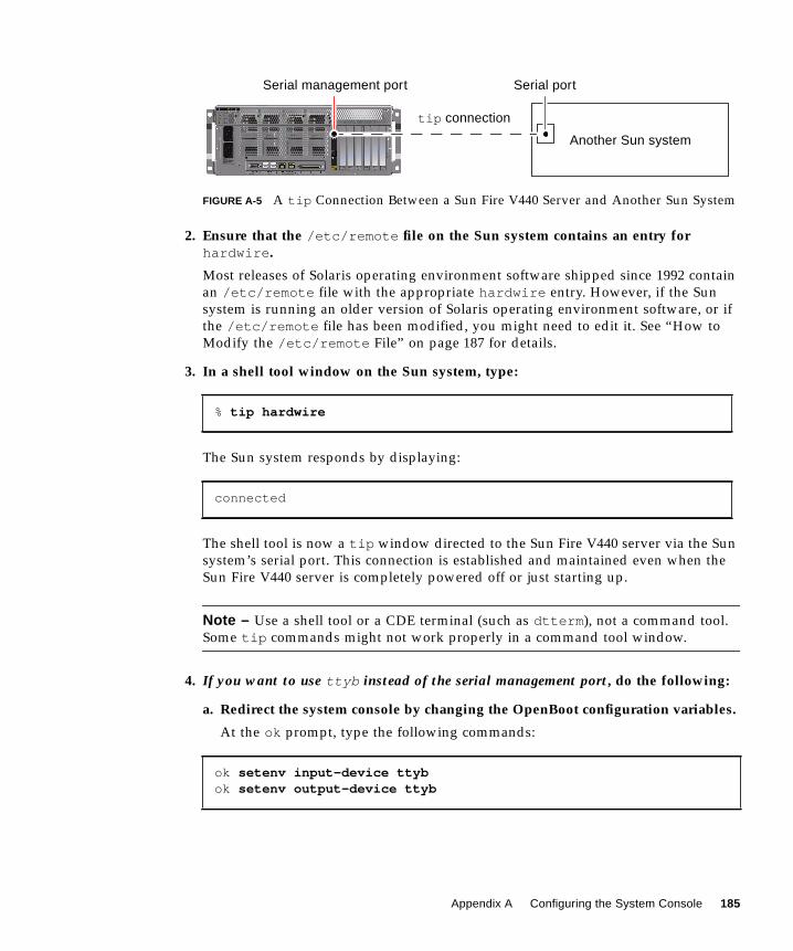
FIGURE A-5 A tip Connection Between a Sun Fire V440 Server and Another Sun System
2. Ensure that the /etc/remote file on the Sun system contains an entry forhardwire .
Most releases of Solaris operating environment software shipped since 1992 contain
an /etc/remote file with the appropriate hardwire entry. However, if the Sun
system is running an older version of Solaris operating environment software, or if
the /etc/remote file has been modified, you might need to edit it. See “How to
Modify the /etc/remote File” on page 187 for details.
3. In a shell tool window on the Sun system, type:
The Sun system responds by displaying:
The shell tool is now a tip window directed to the Sun Fire V440 server via the Sun
system’s serial port. This connection is established and maintained even when the
Sun Fire V440 server is completely powered off or just starting up.
Note – Use a shell tool or a CDE terminal (such as dtterm ), not a command tool.
Some tip commands might not work properly in a command tool window.
4. If you want to use ttyb instead of the serial management port, do the following:
a. Redirect the system console by changing the OpenBoot configuration variables.
At the ok prompt, type the following commands:
% tip hardwire
connected
ok setenv input-device ttybok setenv output-device ttyb
Another Sun system
tip connection
Serial portSerial management port
Appendix A Configuring the System Console 185
Note – You can only access the sc> prompt and view POST messages from either
the serial management port or the network management port.
Note – There are many other OpenBoot configuration variables. Although these
variables do not affect which hardware device is used to access the system console,
some of them affect which diagnostic tests the system runs and which messages the
system displays at its console. For details, see “Controlling POST Diagnostics” on
page 13.
b. To cause the changes to take effect, power off the system. Type:
The system permanently stores the parameter changes and powers off.
Note – You can also power off the system using the front panel Power button.
c. Connect the null modem serial cable to the ttyb port on the Sun Fire V440server.
If required, use the DB-9 or DB-25 cable adapter supplied with the server.
d. Power on the system.
See the Sun Fire V440 Server Administration Guide for power-on procedures.
What NextContinue with your installation or diagnostic test session as appropriate. When you
are finished using the tip window, end your tip session by typing ~. (tilde period)
and exit the window. For more information about tip commands, see the tip man
page.
For more information about connecting to and using the ALOM system controller,
see:
■ Sun Advanced Lights Out Manager (ALOM) Online Help
If you have redirected the system console to ttyb and want to change the system
console settings back to use the serial management and network management ports,
see the following:
■ “Reference for System Console OpenBoot Configuration Variable Settings” on
page 196
ok power-off
186 Sun Fire V440 Server Diagnostics and Troubleshooting Guide • July 2003

How to Modify the /etc/remote File
This procedure might be necessary if you are accessing the Sun Fire V440 server
using a tip connection from a Sun system running an older version of the Solaris
operating environment software. You might also need to perform this procedure if
the /etc/remote file on the Sun system has been altered and no longer contains an
appropriate hardwire entry.
Before You Begin
This procedure assumes that you are logged in as superuser to the system console of
a Sun system that you intend to use to establish a tip connection to the Sun Fire
V440 server.
What to Do
1. Determine the release level of Solaris operating environment software installedon the Sun system. Type:
The system responds with a release number.
2. Do one of the following, depending on the number displayed.
■ If the number displayed by the uname -r command is 5.0 or higher:
The server software shipped with an appropriate entry for hardwire in the
/etc/remote file. If you have reason to suspect that this file was altered and the
hardwire entry modified or deleted, check the entry against the following
example and edit it as needed.
# uname -r
CODE EXAMPLE A-1 Entry for hardwire in /etc/remote File (Recent System Software)
hardwire:\
:dv=/dev/term/b:br#9600:el=^C^S^Q^U^D:ie=%$:oe=^D:
Appendix A Configuring the System Console 187

Note – If you intend to use the Sun system’s serial port A rather than serial port B,
edit this entry by replacing /dev/term/b with /dev/term/a .
■ If the number displayed by the uname -r command is less than 5.0:
Check the /etc/remote file and add the following entry if it does not already
exist.
Note – If you intend to use the Sun system’s serial port A rather than serial port B,
edit this entry by replacing /dev/ttyb with /dev/ttya .
What Next
The /etc/remote file is now properly configured. Continue establishing a tipconnection to the Sun Fire V440 server’s system console. See:
■ “How to Access the System Console via tip Connection” on page 184
If you have redirected the system console to ttyb and want to change the system
console settings back to use the serial management and network management ports,
see:
■ “Reference for System Console OpenBoot Configuration Variable Settings” on
page 196
CODE EXAMPLE A-2 Entry for hardwire in /etc/remote File (Older System Software)
hardwire:\
:dv=/dev/ttyb:br#9600:el=^C^S^Q^U^D:ie=%$:oe=^D:
188 Sun Fire V440 Server Diagnostics and Troubleshooting Guide • July 2003
How to Access the System Console viaan Alphanumeric Terminal
Before You Begin
This procedure assumes that you are accessing the Sun Fire V440 server system
console by connecting the serial port of an alphanumeric terminal to the serial
management port (SERIAL MGT) of the Sun Fire V440 server.
What to Do
1. Attach one end of the serial cable to the alphanumeric terminal’s serial port.
Use an RJ-45 null modem serial cable or an RJ-45 serial cable and null modem
adapter. Plug in this cable to the terminal’s serial port connector.
2. Attach the opposite end of the serial cable to the serial management port on theSun Fire V440 server.
3. Connect the alphanumeric terminal’s power cord to an AC outlet.
4. Set the alphanumeric terminal to receive:
■ 9600 baud
■ 8 bits
■ No parity
■ 1 stop bit
■ No handshake protocol
See the documentation accompanying your terminal for information about how to
configure it.
5. If you want to use ttyb instead of the serial management port, do the following:
a. Redirect the system console by changing OpenBoot configuration variables.
At the ok prompt, type the following commands:
ok setenv input-device ttybok setenv output-device ttyb
Appendix A Configuring the System Console 189
Note – You can only access the sc> prompt and view POST messages from either
the serial management port or the network management port.
Note – There are many other OpenBoot configuration variables. Although these
variables do not affect which hardware device is used to access the system console,
some of them affect which diagnostic tests the system runs and which messages the
system displays at its console. For details, see “Controlling POST Diagnostics” on
page 13.
b. To cause the changes to take effect, power off the system. Type:
The system permanently stores the parameter changes and powers off.
Note – You can also power off the system using the front panel Power button.
c. Connect the null modem serial cable to the ttyb port on the Sun Fire V440server.
If required, use the DB-9 or DB-25 cable adapter supplied with the server.
d. Power on the system.
See the Sun Fire V440 Server Administration Guide for power-on procedures.
What Next
You can issue system commands and view system messages using the alphanumeric
terminal. Continue with your installation or diagnostic procedure, as needed. When
you are finished, type the alphanumeric terminal’s escape sequence.
For more information about connecting to and using the ALOM system controller,
see:
■ Sun Advanced Lights Out Manager (ALOM) Online Help
If you have redirected the system console to ttyb and want to change the system
console settings back to use the serial management and network management ports,
see the following:
■ “Reference for System Console OpenBoot Configuration Variable Settings” on
page 196
ok power-off
190 Sun Fire V440 Server Diagnostics and Troubleshooting Guide • July 2003
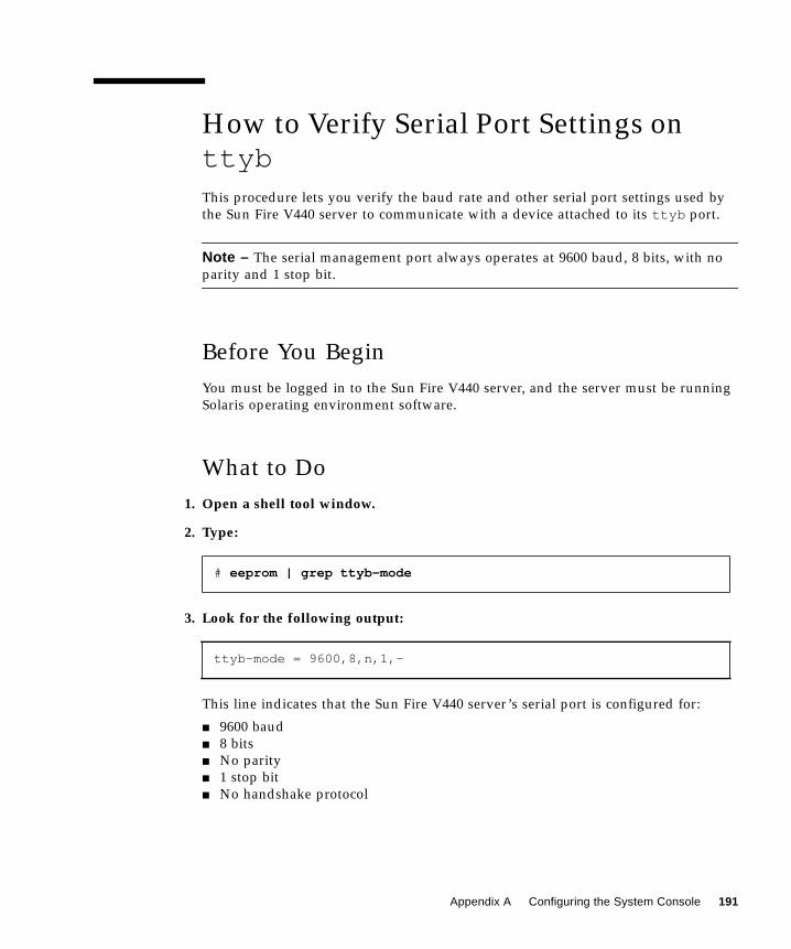
How to Verify Serial Port Settings onttybThis procedure lets you verify the baud rate and other serial port settings used by
the Sun Fire V440 server to communicate with a device attached to its ttyb port.
Note – The serial management port always operates at 9600 baud, 8 bits, with no
parity and 1 stop bit.
Before You Begin
You must be logged in to the Sun Fire V440 server, and the server must be running
Solaris operating environment software.
What to Do
1. Open a shell tool window.
2. Type:
3. Look for the following output:
This line indicates that the Sun Fire V440 server’s serial port is configured for:
■ 9600 baud
■ 8 bits
■ No parity
■ 1 stop bit
■ No handshake protocol
# eeprom | grep ttyb-mode
ttyb-mode = 9600,8,n,1,-
Appendix A Configuring the System Console 191
What Next
For more information about serial port settings, see the eeprom man page. For
instructions on setting OpenBoot configuration variables, see :
■ “How to View and Set OpenBoot Configuration Variables” on page 54
How to Access the System Console via aLocal Graphics Monitor
Before You Begin
After initial system installation, you can install a local graphics monitor and set it up
to access the system console. You cannot use a local graphics monitor to perform
initial system installation, nor can you use a local graphics monitor to view power-
on self-test (POST) messages. For detailed information about system console options,
see:
■ “About Communicating With the System” on page 164
To install a local graphics monitor, you must have:
■ A supported PCI-based graphics frame buffer card and software driver
■ An 8/24-Bit Color Graphics PCI adapter frame buffer card (Sun part number
X3768A or X3769A is currently supported)
■ A monitor with appropriate resolution to support the frame buffer
■ A Sun-compatible USB keyboard (Sun USB Type–6 keyboard)
■ A Sun-compatible USB mouse (Sun USB mouse) and mouse pad
What to Do
1. Install the graphics card into an appropriate PCI slot.
Installation must be performed by a qualified service provider. For further
information, see the Sun Fire V440 Server Parts Installation and Removal Guide or
contact your qualified service provider.
192 Sun Fire V440 Server Diagnostics and Troubleshooting Guide • July 2003
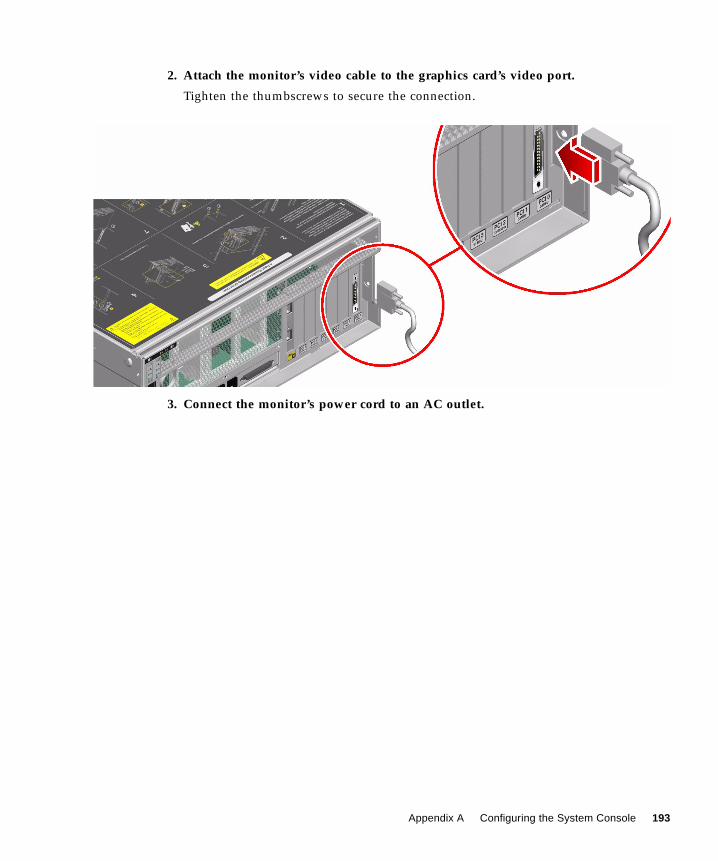
2. Attach the monitor’s video cable to the graphics card’s video port.
Tighten the thumbscrews to secure the connection.
3. Connect the monitor’s power cord to an AC outlet.
Appendix A Configuring the System Console 193
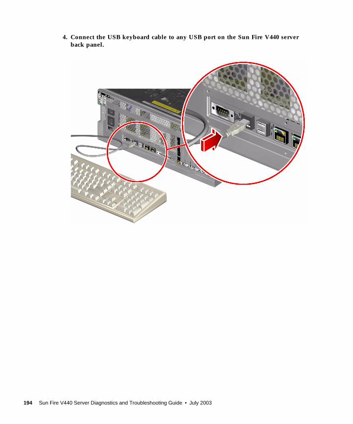
4. Connect the USB keyboard cable to any USB port on the Sun Fire V440 serverback panel.
194 Sun Fire V440 Server Diagnostics and Troubleshooting Guide • July 2003
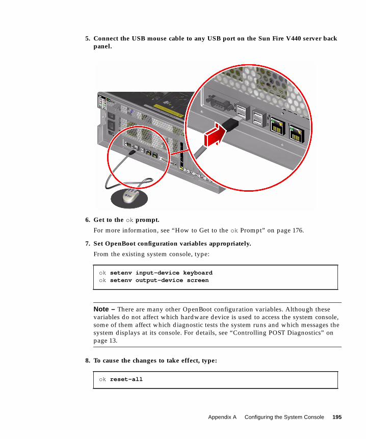
5. Connect the USB mouse cable to any USB port on the Sun Fire V440 server backpanel.
6. Get to the ok prompt.
For more information, see “How to Get to the ok Prompt” on page 176.
7. Set OpenBoot configuration variables appropriately.
From the existing system console, type:
Note – There are many other OpenBoot configuration variables. Although these
variables do not affect which hardware device is used to access the system console,
some of them affect which diagnostic tests the system runs and which messages the
system displays at its console. For details, see “Controlling POST Diagnostics” on
page 13.
8. To cause the changes to take effect, type:
ok setenv input-device keyboardok setenv output-device screen
ok reset-all
Appendix A Configuring the System Console 195
The system stores the parameter changes, and boots automatically when the
OpenBoot configuration variable auto-boot? is set to true (its default value).
Note – To store parameter changes, you can also power cycle the system using the
front panel Power button.
What Next
You can issue system commands and view system messages using your local
graphics monitor. Continue with your installation or diagnostic procedure, as
needed.
If you want to redirect the system console back to the serial management and
network management ports, see:
■ “Reference for System Console OpenBoot Configuration Variable Settings” on
page 196
Reference for System Console OpenBootConfiguration Variable Settings
The Sun Fire V440 system console is directed to the serial management and network
management ports (SERIAL MGT and NET MGT) by default. However, you can
redirect the system console to the serial DB-9 port (ttyb ), or to a local graphics
monitor, keyboard, and mouse. You can also redirect the system console back to the
serial management and network management ports.
196 Sun Fire V440 Server Diagnostics and Troubleshooting Guide • July 2003
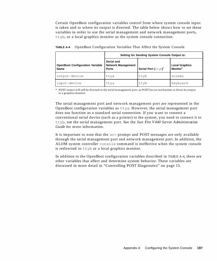
Certain OpenBoot configuration variables control from where system console input
is taken and to where its output is directed. The table below shows how to set these
variables in order to use the serial management and network management ports,
ttyb , or a local graphics monitor as the system console connection.
The serial management port and network management port are represented in the
OpenBoot configuration variables as ttya . However, the serial management port
does not function as a standard serial connection. If you want to connect a
conventional serial device (such as a printer) to the system, you need to connect it to
ttyb , not the serial management port. See the Sun Fire V440 Server AdministrationGuide for more information.
It is important to note that the sc> prompt and POST messages are only available
through the serial management port and network management port. In addition, the
ALOM system controller console command is ineffective when the system console
is redirected to ttyb or a local graphics monitor.
In addition to the OpenBoot configuration variables described in TABLE A-4, there are
other variables that affect and determine system behavior. These variables are
discussed in more detail in “Controlling POST Diagnostics” on page 13.
TABLE A-4 OpenBoot Configuration Variables That Affect the System Console
OpenBoot Configuration VariableName
Setting for Sending System Console Output to:
Serial andNetwork ManagementPorts Serial Port ( ttyb )*
* POST output will still be directed to the serial management port, as POST has no mechanism to direct its outputto a graphics monitor.
Local GraphicsMonitor *
output-device ttya ttyb screen
input-device ttya ttyb keyboard
Appendix A Configuring the System Console 197

198 Sun Fire V440 Server Diagnostics and Troubleshooting Guide • July 2003
Index
SYMBOLS/etc/remote file, 185
/etc/remote file, how to modify, 187
/etc/syslogd.conf file, 24
/var/adm/messages file
error logging, 24
use in troubleshooting after an unexpected
reboot, 137
use in troubleshooting with operating system
responding, 130
AActivity LED (disk drive), 64
address
bitwalk (POST diagnostic), 10
of I2C devices (table), 49
agents, Sun Management Center, 37
ALOM (Advanced Lights Out Manager)
See also system controller
accessing system console, 111
cable fault isolation and, 33
email notification and, 35
guided tour of, 79
isolation of SCC faults and, 34
system monitoring with, 35, 79
use in troubleshooting, 111
warning thresholds reported by, 81, 83
ALOM boot log
use in troubleshooting after an unexpected
reboot, 134
use in troubleshooting booting problems, 158
use in troubleshooting Fatal Reset errors and
RED State Exceptions, 146
ALOM commands, See system controller
commands
ALOM event log
use in troubleshooting, 143
use in troubleshooting after an unexpected
reboot, 131
use in troubleshooting booting problems, 154
use in troubleshooting with operating system
responding, 127
ALOM run log
use in troubleshooting after an unexpected
reboot, 132
use in troubleshooting booting problems, 155
use in troubleshooting Fatal Reset errors and
RED State Exceptions, 144
alphanumeric terminal
baud rate verification, 191
system console access and, 189
auto-boot? variable
setting, 171
setting for OpenBoot Diagnostics, 13
use in troubleshooting booting problems, 159
Automatic System Recovery (ASR)
enabling, OpenBoot configuration variables
for, 110
ensuring reliability, 15
use in troubleshooting, 110
199

Bbanks, memory
physical and logical, 43
POST reference, 43
baud rate
alphanumeric terminal setting, 189
verifying, 191
Big Admin
troubleshooting resource, 106
Web site, 106
BIST, See built-in self-test
BMC Patrol, See third-party monitoring tools
boot process, summary of stages, 8
Boot PROM
function of, 9
illustration of, 9
boot-device variable, use in troubleshooting
booting problems, 159
bootmode diag command (system controller), 91
bounds file, 117
break command (system controller), 172, 177
Break key (alphanumeric terminal), 173, 177
built-in self-test (BIST)
IEEE 1275-compatible, 16, 57, 61
test-args variable and, 17
bus repeater circuit, 3
Ccables
connector board power, 33
DVD-ROM drive, 33
isolating faults in, 33, 40
keyboard and mouse, 195
SCSI data, 34
system configuration card reader, 34
system control keyswitch, 34
central processing unit, See CPU
Cisco AS2511-RJ, See terminal server
clock speed (CPU), 30
connector board power cable, isolating faults in, 33
console command (system controller), 92, 172,
176, 177
console, See system console
consolehistory boot -v command (system
controller)
use in troubleshooting, 134
use in troubleshooting booting problems, 158
use in troubleshooting Fatal Reset errors and
RED State Exceptions, 146
consolehistory run -v command (system
controller)
use in troubleshooting after an unexpected
reboot, 132
use in troubleshooting booting problems, 155
use in troubleshooting Fatal Reset errors and
RED State Exceptions, 144
core dump
enabling for troubleshooting, 113
testing, 116
use in troubleshooting, 113
CPU (central processing unit)
displaying information about, 30
master, 9, 10
numbering of processor modules, 46
Ddata bitwalk (POST diagnostic), 10
device paths, hardware, 19, 23
device tree
collecting data from, 37
defined, 15
Solaris, displaying, 24
df -k command (Solaris), 115
diag-device variable, use in troubleshooting
booting problems, 159
diag-level variable
setting, 13
setting for OpenBoot Diagnostics testing, 16
use in troubleshooting hanging system, 161
diagnostic tests
availability of during boot process (table), 32
bypassing, 14
bypassing temporarily, 15, 59
enabling, 57
terms in output (table), 51
200
diagnostic tools
informal, 2, 23
summary of (table), 2
tasks performed with, 5
diagnostics mode
how to put server in, 57
purpose of, 8
diag-script variable, 13
diag-switch? variable
setting, 13
use in troubleshooting hanging systems, 161
disk drive LEDs, isolating faults with, 64
dumpadm command (Solaris), 114
dumpadm -s command (Solaris), 116
DVD-ROM drive cable, isolating faults in, 33
DVD-ROM LED, isolating faults with, 64
Eerror logging, 144
error messages
OpenBoot Diagnostics, interpreting, 20
POST, interpreting, 11
error states, system, 123
error-reset-recovery variable, setting for
troubleshooting, 109
exercising the system
with Hardware Diagnostic Suite, 42
with SunVTS, 40, 96
externally initiated reset (XIR)
accessing the ok prompt, 177
use in troubleshooting, 109
use in troubleshooting hanging system, 161, 173
FFatal Reset errors
responding to, 124
troubleshooting, 142
fault isolation
procedures for, 53
tools according to FRU (table), 32
using OpenBoot Diagnostics tests, 20, 67
using POST, 12, 65
using system LEDs, 62
field-replaceable unit, See FRU
firmware
See also OpenBoot firmware
corruption of, 15
system (drawing of), 9
firmware patch management, 107
FRU (field-replaceable unit)
boundaries between, 12
covered by different diagnostic tools (table), 32,
39
data stored in SEEPROM, 30
hardware revision level, 30
hierarchical list of, 29
manufacturer, 30
not isolated by fault isolating tools (table), 33
not isolated by system exercising tools (table), 40
part number, 30
POST and, 12
fsck command (Solaris), 174
Ggo command (OpenBoot), 174
graceful system shutdown, 172, 177
HH/W under test , See interpreting error messages
“hangs,” system, 15
hardware device paths, 19, 23
Hardware Diagnostic Suite
about exercising the system with, 42
Sun Management Center add-on, 38
hardware revision, displaying with showrev , 31
hardware watchdog mechanism, use in
troubleshooting, 109
hardware, troubleshooting, 119
HP Openview, See third-party monitoring tools
II2C device addresses (table), 49
IDE bus, 22
IEEE 1275-compatible built-in self-test, 16, 57, 61
201
informal diagnostic tools, 2, 23
See also LEDs
init command (Solaris), 172, 177
input-device variable, 14
Integrated Drive Electronics, See IDE bus
intermittent problem, 10, 39, 42
interpreting error messages
I2C tests, 20
OpenBoot Diagnostics tests, 20
POST, 11
iostat -E command (Solaris)
use in troubleshooting after an unexpected
reboot, 140
use in troubleshooting Fatal Reset errors and
RED State Exceptions, 152
iostat -xtc command (Solaris)
use in troubleshooting after an unexpected
reboot, 140
use in troubleshooting Fatal Reset errors and
RED State Exceptions, 152
isolating faults
tools according to FRU (table), 32
using OpenBoot Diagnostics tests, 20, 67
using POST, 12, 65
J“J” numbers, 11, 44
Kkeyboard, attaching, 194
keyswitch position, use in troubleshooting hanging
system, 160
LL1-A key sequence, 177
LEDs
Activity (disk drive), 64
isolating faults with, 62
Locator (system), 55, 63
OK-to-Remove
disk drive, 64
power supply, 63
Power OK (power supply), 64
Power/Activity (DVD-ROM drive), 64
Service Required
disk drive, 64
power supply, 64
system, 63
Standby Available (power supply), 64
System Activity (system), 63
use in troubleshooting, 122
light-emitting diode, See LEDs
Locator LED (system), 55, 63
log files, 24, 37
logical view (Sun Management Center), 37
Mmanual system reset, 173, 177
master CPU, 9, 10
memory banks
physical and logical, 43
POST reference, 43
memory initialization, 136
monitor, attaching, 192
monitoring the system
email notification and, 34, 35
with OpenBoot commands, 21, 94
with Solaris commands, 24, 93
with Sun Management Center, 74
with the ALOM system controller, 35, 79
mouse, attaching, 195
Nnetwork management port (NET MGT)
access to both ALOM system controller and
system console, 175
default system console connection, 167
202
OOBDIAG, See OpenBoot Diagnostics tests
obdiag-trigger variable
setting, 14
use in troubleshooting hanging system, 161
ok prompt
risks in issuing commands from, 174
ways to access, 172, 176
OK-to-Remove LED
disk drive, 64
power supply, 63
OpenBoot commands
printenv , 21, 161
probe-ide , 22
probe-scsi and probe-scsi-all , 21
reset-all , 195
risks of, 174
show-devs , 23
show-post-results , 121
OpenBoot configuration variables
auto-boot? , 13
diag-level , 13
diag-script , 13
diag-switch? , 13
displaying with printenv , 21
enabling ASR, 110
input-device , 14
obdiag-trigger , 14
output-device , 14
post-trigger , 14
purpose of, 10, 13
system console settings, 196
table of, 13
OpenBoot Diagnostics messages, 136
OpenBoot Diagnostics tests
controlling, 16
described, 16
descriptions of (table), 47
error messages, interpreting, 20
hardware device paths in, 19
interactive menu, 17
purpose and coverage of, 16
running from the ok prompt, 19
test command, 19
test-all command, 19
triggering when to run, 14
OpenBoot firmware, 9, 53, 74, 95
OpenBoot PROM initialization, 135
operating environment software, suspending, 174
operating system panic, 15
output-device variable, 14
overtemperature condition, determining with
prtdiag , 28
Ppanic, operating system, 15
parity
alphanumeric terminal setting, 189
verifying, 191
patch management
firmware, 107
software, 107
patches
determining with showrev , 31
installed, 31
PCI (Peripheral Component Interconnect) card,
frame buffer card, 192
physical view (Sun Management Center), 37
ping command (Solaris), use in troubleshooting
hanging system, 160
pkgadd utility, 102
pkginfo command (Solaris), 101
POST (power-on self-test)
boot messages, 134
controlling, 13
criteria for passing, 10
decoding terms from, 12
defined, 9
error messages, interpreting, 11
fault isolation beyond FRU level, 12
how to run, 65
limitations of message display, 14
master CPU and, 10
persistent problems and, 10
purpose of, 10
repair depot and, 12
triggering when to run, 14
post-trigger variable
setting, 14
use in troubleshooting hanging system, 161
Power OK LED (power supply), 64
power supply LEDs, isolating faults with, 63
203
Power/Activity LED (DVD-ROM drive), 64
poweroff command (system controller), 91
poweron command (system controller), 91
power-on self-test, See POST
printenv command (OpenBoot)
described, 21
use in troubleshooting hanging system, 161
probe-ide command (OpenBoot), 22, 173
probe-scsi and probe-scsi-all commands
(OpenBoot), 21, 173
processor speed, displaying, 30
prtconf command (Solaris), 24
prtdiag -v command (Solaris)
defined, 25
use in troubleshooting, 121
use in troubleshooting after an unexpected
reboot, 137
use in troubleshooting Fatal Reset errors and
RED State Exceptions, 149
use in troubleshooting with operating system
responding, 128
prtfru command (Solaris), 29
ps -ef command (Solaris)
use in troubleshooting after an unexpected
reboot, 139
use in troubleshooting Fatal Reset errors and
RED State Exceptions, 151
use in troubleshooting hanging system, 160
psrinfo command (Solaris), 30
Rraidctl command (Solaris), use in
troubleshooting after an unexpected reboot, 141
reboot, unexpected, 126
RED State Exceptions
responding to, 124
troubleshooting, 142
repair depot, POST capabilities and, 12
reset events, kinds of, 14
reset -x command (system controller), 173
reset, manual system, 173, 177
reset-all command (OpenBoot), 195
revision, hardware and software, displaying with
showrev , 31
run levels
explained, 171
ok prompt and, 171
Ssavecore directory, 117
sc> prompt
relationship to ok prompt, 175
ways to access, 170
SCC reader cable, See system configuration card
reader cable
SCC reader, See system configuration card reader
SCC, See system configuration card
SCSI data cable, isolating faults in, 34
SCSI devices, diagnosing problems in, 21
SEAM (Sun Enterprise Authentication
Mechanism), 42
serial management port (SERIAL MGT)
access to both ALOM system controller and
system console, 175
default system console connection, 167
defined, 164
devices for accessing the system console, 164
how to use, 178
tip connection, 184
SERIAL MGT, See serial management port
serial port, connecting to, 189
Service Required LED
disk drive, 64
power supply, 64
system, 63
show-devs command (OpenBoot), 23
showenvironment command (system controller)
displaying environmental data, 80
monitoring the server, 35
use in troubleshooting with operating system
responding, 128
showfru command (system controller), 84
showlogs command (system controller)
use in system monitoring, 85
use in troubleshooting, 143
use in troubleshooting after an unexpected
reboot, 131
204 Sun Fire V440 Server Diagnostics and Troubleshooting Guide • July 2003

use in troubleshooting booting problems, 154
use in troubleshooting with operating system
responding, 127
show-obdiag-results command, use in
troubleshooting, 121
showplatform command (system controller), 35,
91
show-post-results command (OpenBoot), use
in troubleshooting, 121
showrev command (Solaris), 31
showusers command (system controller), 35, 90
shut down, gracefully, advantages of, 172, 177
shutdown command (Solaris), 172, 177
software patch management, 107
software revision, displaying with showrev , 31
Solaris commands
df -k , 115
dumpadm, 114
dumpadm -s , 116
fsck , 174
init , 172, 177
iostat -E , 140, 152
iostat -xtc , 140, 152
ping , 160
pkginfo , 101
prtconf , 24
prtdiag -v , 25, 128, 137, 149
prtfru , 29
ps -ef , 139, 151, 160
psrinfo , 30
raidctl , 141
showrev , 31
shutdown , 172, 177
swap -l , 114
sync , 161, 173
uadmin , 172
SRS Net Connect, 108
stages of boot process, 8
Standby Available LED (power supply), 64
standby power, ALOM and, 35
stress testing
See also exercising the system
Sun VTS, use in, 40
Sun Enterprise Authentication Mechanism
(SEAM), 42
Sun Explorer Data Collector, 108
Sun Install Check tool, 107
Sun Management Center
agents, 74
generating reports with, 38
guided tour of, 74
monitoring with, 74
servers and consoles, 74
tracking systems informally with, 38
Sun Remote Services Net Connect, 108
Sun Validation and Test Suite, See SunVTS
SunMC, See Sun Management Center
SunSolve Online
troubleshooting resources, 106
web site, 106
SunVTS
checking if installed, 100
exercising the system with, 40, 96
guided tour of, 96
stress testing with, 40
suspending the operating environment
software, 174
swap device, saving core dump, 113
swap -l command (Solaris), 114
swap space, calculating, 114
sync command (Solaris)
after generating an XIR, 173
testing core dump setup, 116
use in troubleshooting hanging system, 161
System Activity LED (system), 63
system banner display, 135
system configuration card reader cable, isolating
faults in, 34
system console
default configuration explained, 164, 166
defined, 164
how to access via
alphanumeric terminal, 189
local graphics monitor, 192
tip connection, 184
local graphics monitor and, 169
logging error messages, 111
messages, 8
OpenBoot configuration variables,
reference, 196
other ways to configure, 168
tip connection, 167, 184
205

system control keyswitch cable, isolating faults
in, 34
system control keyswitch, changing positions in
troubleshooting, 159
system controller
See also ALOM
introduced, 8
SCSI backplane and, 33
skipping diagnostic tests and, 15
system controller commands
See also ALOM
bootmode diag , 91
break , 172, 177
console , 92, 172, 176, 177
consolehistory boot -v , 92, 134, 146, 158
consolehistory run -v , 132, 144, 155
escape sequence (#.), 80, 170, 176
poweroff , 91
poweron , 91
reset -x , 173
showenvironment , 35, 80, 128
showfru , 84
showlogs , 85
showplatform , 35, 91
showusers , 35, 90
system “hangs”, 15
system LEDs, isolating faults with, 62
system memory
determining amount of, 24
identifying modules, 43
Ttarget number (probe-scsi ), 21
terminal server, 181
terminal, baud rate verification, 191
terms, in diagnostic output (table), 51
test command (OpenBoot Diagnostics tests), 19
test-all command (OpenBoot Diagnostics
tests), 19
test-args variable, keywords for (table), 17
third-party monitoring tools, 38
thresholds, warning reported by ALOM, 81, 83
tip connection, 167, 184
Tivoli Enterprise Console, See third-party
monitoring tools
tree, device
collecting data from, 37
defined, 15
troubleshooting
booting problem, 154
error information, 120
error logging, 111
Fatal Reset errors, 142
hanging system, 160
RED State Exceptions, 142
systematic approach, 120
unexpected reboot, 131
using configuration variables for, 109
with the operating system responding, 126
troubleshooting tasks, 119
Uuadmin command (Solaris), 172
unit number (probe-scsi ), 21
Universal Serial Bus (USB) devices, running
OpenBoot Diagnostics self-tests on, 19
Vverifying baud rate, 191
Wwarning thresholds reported by ALOM, 81, 83
XXIR, See externally initiated reset
206 Sun Fire V440 Server Diagnostics and Troubleshooting Guide • July 2003