Embed Size (px)
Citation preview

Sun Microsystems, Inc.www.sun.com
Submit comments about this document at: http://www.sun.com/hwdocs/feedback
Sun Fire™ V215 and V245 ServersService Manual
Part No. 819-3038-11January 2008, Revision A

PleaseRecycle
Copyright 2008 Sun Microsystems, Inc., 4150 Network Circle, Santa Clara, California 95054, U.S.A. All rights reserved.
Sun Microsystems, Inc. has intellectual property rights relating to technology that is described in this document. In particular, and withoutlimitation, these intellectual property rights may include one or more of the U.S. patents listed at http://www.sun.com/patents and one ormore additional patents or pending patent applications in the U.S. and in other countries.
This document and the product to which it pertains are distributed under licenses restricting their use, copying, distribution, anddecompilation. No part of the product or of this document may be reproduced in any form by any means without prior written authorization ofSun and its licensors, if any.
Third-party software, including font technology, is copyrighted and licensed from Sun suppliers.
Parts of the product may be derived from Berkeley BSD systems, licensed from the University of California. UNIX is a registered trademark inthe U.S. and in other countries, exclusively licensed through X/Open Company, Ltd.
Sun, Sun Microsystems, the Sun logo, docs.sun.com, Sun Fire, SunVTS, OpenBoot, and Solaris are trademarks or registered trademarks of SunMicrosystems, Inc. in the U.S. and in other countries.
All SPARC trademarks are used under license and are trademarks or registered trademarks of SPARC International, Inc. in the U.S. and in othercountries. Products bearing SPARC trademarks are based upon an architecture developed by Sun Microsystems, Inc.
The OPEN LOOK and Sun™ Graphical User Interface was developed by Sun Microsystems, Inc. for its users and licensees. Sun acknowledgesthe pioneering efforts of Xerox in researching and developing the concept of visual or graphical user interfaces for the computer industry. Sunholds a non-exclusive license from Xerox to the Xerox Graphical User Interface, which license also covers Sun’s licensees who implement OPENLOOK GUIs and otherwise comply with Sun’s written license agreements.
U.S. Government Rights—Commercial use. Government users are subject to the Sun Microsystems, Inc. standard license agreement andapplicable provisions of the FAR and its supplements.
DOCUMENTATION IS PROVIDED "AS IS" AND ALL EXPRESS OR IMPLIED CONDITIONS, REPRESENTATIONS AND WARRANTIES,INCLUDING ANY IMPLIED WARRANTY OF MERCHANTABILITY, FITNESS FOR A PARTICULAR PURPOSE OR NON-INFRINGEMENT,ARE DISCLAIMED, EXCEPT TO THE EXTENT THAT SUCH DISCLAIMERS ARE HELD TO BE LEGALLY INVALID.
Copyright 2008 Sun Microsystems, Inc., 4150 Network Circle, Santa Clara, Californie 95054, Etats-Unis. Tous droits réservés.
Sun Microsystems, Inc. a les droits de propriété intellectuels relatants à la technologie qui est décrit dans ce document. En particulier, et sans lalimitation, ces droits de propriété intellectuels peuvent inclure un ou plus des brevets américains énumérés à http://www.sun.com/patents etun ou les brevets plus supplémentaires ou les applications de brevet en attente dans les Etats-Unis et dans les autres pays.
Ce produit ou document est protégé par un copyright et distribué avec des licences qui en restreignent l’utilisation, la copie, la distribution, et ladécompilation. Aucune partie de ce produit ou document ne peut être reproduite sous aucune forme, par quelque moyen que ce soit, sansl’autorisation préalable et écrite de Sun et de ses bailleurs de licence, s’il y ena.
Le logiciel détenu par des tiers, et qui comprend la technologie relative aux polices de caractères, est protégé par un copyright et licencié par desfournisseurs de Sun.
Des parties de ce produit pourront être dérivées des systèmes Berkeley BSD licenciés par l’Université de Californie. UNIX est une marquedéposée aux Etats-Unis et dans d’autres pays et licenciée exclusivement par X/Open Company, Ltd.
Sun, Sun Microsystems, le logo Sun, docs.sun.com, Sun Fire, SunVTS, OpenBoot, et Solaris sont des marques de fabrique ou des marquesdéposées de Sun Microsystems, Inc. aux Etats-Unis et dans d’autres pays.
Toutes les marques SPARC sont utilisées sous licence et sont des marques de fabrique ou des marques déposées de SPARC International, Inc.aux Etats-Unis et dans d’autres pays. Les produits portant les marques SPARC sont basés sur une architecture développée par SunMicrosystems, Inc.
L’interface d’utilisation graphique OPEN LOOK et Sun™ a été développée par Sun Microsystems, Inc. pour ses utilisateurs et licenciés. Sunreconnaît les efforts de pionniers de Xerox pour la recherche et le développement du concept des interfaces d’utilisation visuelle ou graphiquepour l’industrie de l’informatique. Sun détient une license non exclusive de Xerox sur l’interface d’utilisation graphique Xerox, cette licencecouvrant également les licenciées de Sun qui mettent en place l’interface d ’utilisation graphique OPEN LOOK et qui en outre se conformentaux licences écrites de Sun.
LA DOCUMENTATION EST FOURNIE "EN L’ÉTAT" ET TOUTES AUTRES CONDITIONS, DECLARATIONS ET GARANTIES EXPRESSESOU TACITES SONT FORMELLEMENT EXCLUES, DANS LA MESURE AUTORISEE PAR LA LOI APPLICABLE, Y COMPRIS NOTAMMENTTOUTE GARANTIE IMPLICITE RELATIVE A LA QUALITE MARCHANDE, A L’APTITUDE A UNE UTILISATION PARTICULIERE OU AL’ABSENCE DE CONTREFAÇON.

Contents
Preface xv
1. Diagnosing Server Performance and Faults 1–1
1.1 Diagnostic Tools Overview 1–2
1.2 Choosing a Fault Isolation Tool 1–3
1.3 POST Diagnostics 1–6
1.3.1 Starting POST Diagnostics 1–6
1.3.2 Controlling POST Diagnostics 1–7
1.4 OpenBoot Diagnostics 1–9
1.4.1 Starting OpenBoot Diagnostics 1–9
1.4.2 Controlling OpenBoot Diagnostics Tests 1–9
1.4.2.1 test and test-all Commands 1–10
1.4.2.2 What OpenBoot Diagnostics Error Messages Tell You1–11
1.4.3 OpenBoot Diagnostic Commands 1–12
1.4.3.1 probe-scsi and probe-scsi-all Commands 1–12
1.4.3.2 probe-ide Command 1–13
1.4.3.3 show-devs Command 1–14
1.4.3.4 Running OpenBoot Commands 1–14
1.5 Operating System Diagnostic Tools 1–15
iii

1.5.1 Error and System Message Log Files 1–15
1.5.2 Solaris System Information Commands 1–15
1.5.2.1 prtconf Command 1–16
1.5.2.2 prtdiag Command 1–16
1.5.2.3 prtfru Command 1–17
1.5.2.4 psrinfo Command 1–17
1.5.2.5 showrev Command 1–17
1.6 Recent Diagnostic Test Results 1–17
1.6.1 Viewing Recent Test Results 1–18
1.7 Additional Diagnostic Tests for Specific Devices 1–18
1.7.1 Confirming That the Internal Hard Drives Are Active 1–18
1.7.2 Confirming That the External Hard Drives Are Active 1–19
1.7.3 Confirming That the DVD Super-Multi Drive Is Connected 1–20
1.7.4 Checking Network Connections on the Primary Network 1–20
1.7.5 Checking Network Connections on Additional NetworkInterfaces 1–21
2. Replacing Hot-Pluggable and Hot-Swappable CRUs 2–1
2.1 Devices That Are Hot-Pluggable or Hot-Swappable 2–1
2.2 Hot-Plugging a Hard Drive 2–2
2.2.1 Removing a Hard Drive 2–3
2.2.2 Installing a Hard Drive 2–5
2.3 Hot-Swapping a Fan Tray 2–8
2.3.1 Removing a Fan Tray 2–8
2.3.2 Installing a Fan Tray 2–10
2.4 Hot-Swapping a Hard Drive Fan Tray 2–11
2.4.1 Removing a Hard Drive Fan Tray 2–12
2.4.2 Installing a Hard Drive Fan Tray 2–13
2.5 Hot-Swapping a Power Supply 2–14
iv Sun Fire V215 and V245 Servers Service Manual • January 2008

2.5.1 Removing a Power Supply 2–14
2.5.2 Installing a Power Supply 2–16
3. Replacing Cold-Swappable FRUs 3–1
3.1 Safety Information 3–2
3.1.1 Safety Symbols 3–2
3.1.2 Electrostatic Discharge Safety Measures 3–3
3.1.2.1 Using an Antistatic Wrist Strap 3–3
3.1.2.2 Using an Antistatic Mat 3–3
3.2 Procedures for Parts Replacement 3–3
3.2.1 Required Tools 3–4
3.2.2 Powering Off the Server – ALOM Command Line 3–4
3.2.3 Powering Off the Server – Graceful Shutdown 3–5
3.2.4 Powering Off the Server – Emergency Shutdown 3–5
3.2.5 Extending the Server to the Maintenance Position – RackmountedServers Only 3–6
3.2.6 Removing a Server From the Rack 3–7
3.2.7 Performing Electrostatic Discharge – Antistatic PreventionMeasures 3–9
3.2.8 Removing Power From the Server 3–10
3.2.9 Removing the Rear Cover 3–10
3.2.10 Removing the Bezel 3–11
3.2.11 Removing the Front Cover 3–13
3.2.12 (Sun Fire V245) Removing the Air Baffle 3–14
3.2.13 (Sun Fire V245) Installing the Air Baffle 3–15
3.3 Removing and Installing FRUs 3–16
3.3.1 Removing PCI-E and PCI-X Cards 3–17
3.3.2 Installing PCI-E or PCI-X Cards 3–19
3.3.3 Removing PCI-E and PCI-X Riser Boards 3–20
3.3.4 Installing PCI-E or PCI-X Riser Boards 3–22
Contents v

3.3.5 Removing DIMMs 3–23
3.3.6 Installing DIMMs 3–26
3.3.7 Removing the Motherboard Assembly 3–28
3.3.8 Installing the Motherboard Assembly 3–34
3.3.9 Removing the Power Distribution Board 3–36
3.3.10 Installing the Power Distribution Board 3–41
3.3.11 Removing the Front Indicator Board 3–43
3.3.12 Installing the Front Indicator Board 3–44
3.3.13 Removing the Fan Tray Connector Boards 3–44
3.3.14 Installing the Fan Tray Connector Boards 3–45
3.3.15 Removing the Front I/O Board 3–46
3.3.16 Installing the Front I/O Board 3–47
3.3.17 Removing the DVD Super-Multi Drive 3–48
3.3.18 Installing the DVD Super-Multi Drive 3–49
3.3.19 Removing the Hard Drive Backplane 3–50
3.3.20 Installing the Hard Drive Backplane 3–52
3.3.21 Removing the Hard Drive Fan Tray 3–53
3.3.22 Installing the Hard Drive Fan Tray 3–54
3.3.23 (Sun Fire V245) Removing the Hard Drive Fan Tray ConnectorBoard 3–55
3.3.24 (Sun Fire V245) Installing the Hard Drive Fan Tray ConnectorBoard 3–56
3.3.25 Removing the Battery 3–57
3.3.26 Installing the Battery 3–58
3.3.27 Removing NVRAM 3–59
3.3.28 Installing NVRAM 3–60
3.4 Procedures for Finishing Up 3–60
3.4.1 Installing the Front Cover and Bezel 3–60
3.4.2 Installing the Rear Cover 3–62
vi Sun Fire V215 and V245 Servers Service Manual • January 2008
3.4.3 Reinstalling the Server in the Rack 3–63
3.4.4 Returning the Server to the Normal Rack Position 3–65
3.4.5 Applying Power to the Server 3–66
A. DIMM and PCI Card Guidelines A–1
B. Customer and Field-Replaceable Units B–1
Contents vii

viii Sun Fire V215 and V245 Servers Service Manual • January 2008

Figures
FIGURE 1-1 Choosing a Tool to Isolate Hardware Faults 1–5
FIGURE 2-1 Locating the Hard Drive Release Button and Latch 2–4
FIGURE 2-2 Removing a Fan Tray 2–9
FIGURE 2-3 Top Fan, System Required Indicator, Locator Indicators, and Locator Button 2–11
FIGURE 2-4 Failure and Service Required Indicators 2–11
FIGURE 2-5 Hard Drive Fan Tray – Sun Fire V245 Server 2–13
FIGURE 2-6 Location of the Power Supplies and Release Latches 2–15
FIGURE 2-7 Rotating the Cable Management Arm to Access the Server Power Supplies 2–16
FIGURE 3-1 Locator Indicator/Locator Button 3–6
FIGURE 3-2 Slide Release Latches 3–7
FIGURE 3-3 Metal Lever and Cable Management Arm 3–8
FIGURE 3-4 Release Tabs and Slide Assembly 3–9
FIGURE 3-5 Removing the Rear Cover 3–11
FIGURE 3-6 Front Cover, Front Cover Door, and Latch – Sun Fire V245 3–12
FIGURE 3-7 Removing the Bezel From the Server – Sun Fire V245 3–13
FIGURE 3-8 Air Baffle, Guide Pins, and Handle – Sun Fire V245 3–15
FIGURE 3-9 Location of PCI-E and PCI-X Slots, and PCI Hold-Down Bracket – Sun Fire V215 3–18
FIGURE 3-10 Location of PCI-E and PCI-X Slots, and PCI Hold-Down Bracket – Sun Fire V245 3–18
FIGURE 3-11 Riser Board and PCI Card Connector – Sun Fire V215 3–19
FIGURE 3-12 Installing a PCI Long Card – Sun Fire V245 3–20
ix

FIGURE 3-13 Riser Boards and PCI Option Cards – Sun Fire V215 3–21
FIGURE 3-14 PCI-E and PCI-X Riser Boards 3–22
FIGURE 3-15 Removing the Air Baffle – Sun Fire V215 3–25
FIGURE 3-16 Removing DIMMs 3–26
FIGURE 3-17 Motherboard Assembly 3–28
FIGURE 3-18 PCI-X and PCI-E Riser Boards – Sun Fire V215 3–29
FIGURE 3-19 PCI-X Riser Board Standoff – Sun Fire V215 3–30
FIGURE 3-20 Motherboard to Front I/O Board Cable 3–31
FIGURE 3-21 Motherboard/SAS Backplane Cable Connector and Screws 3–32
FIGURE 3-22 Removing the Motherboard Assembly Screws 3–33
FIGURE 3-23 Removing the Motherboard Assembly From the Chassis 3–34
FIGURE 3-24 Installing the Motherboard Assembly 3–35
FIGURE 3-25 Power Supply Release Latches – Sun Fire V245 3–37
FIGURE 3-26 Upper and Lower Cable Retainers and Motherboard/SAS Backplane Cable 3–38
FIGURE 3-27 Sun Fire V215 (January 2008) Support Bracket Removal 3–39
FIGURE 3-28 Motherboard/SAS Backplane Cable Routing 3–40
FIGURE 3-29 Removing the Power Distribution Board 3–41
FIGURE 3-30 Removing the Front Indicator Board 3–43
FIGURE 3-31 Removing the Fan Tray Connector Board 3–45
FIGURE 3-32 Removing the Front I/O Board 3–47
FIGURE 3-33 Upper Cable Retainer, Motherboard/SAS Backplane Cable, DVD Super-Multi Drive, andSpring Latch 3–49
FIGURE 3-34 Removing the Hard Drive Backplane – Sun Fire V215 3–51
FIGURE 3-35 Removing the Hard Drive Backplane – Sun Fire V245 3–51
FIGURE 3-36 Opening the Rear Cover Door – Sun Fire V245 3–53
FIGURE 3-37 Hard Drive Fan Tray – Sun Fire V245 3–54
FIGURE 3-38 Hard Drive Fan Tray Cage and Screws 3–55
FIGURE 3-39 Hard Drive Fan Tray Connector Board – Connector J1 3–56
FIGURE 3-40 Removing the Battery 3–58
FIGURE 3-41 Removing NVRAM 3–59
x Sun Fire V215 and V245 Servers Service Manual • January 2008

FIGURE 3-42 Installing the Bezel 3–61
FIGURE 3-43 Installing the Front Cover – Sun Fire V245 Server 3–62
FIGURE 3-44 Installing the Rear Cover – Sun Fire V215 server 3–63
FIGURE 3-45 Returning the Server to the Rack 3–64
FIGURE 3-46 Release Tabs – Rails 3–65
FIGURE 3-47 Installing the Cable Management Arm (CMA) 3–66
FIGURE A-1 DIMM Layout A–2
FIGURE B-1 Customer and Field-Replaceable Units, Part 1 of 2 B–2
FIGURE B-2 Customer and Field-Replaceable Units, Part 2 of 1 B–3
Figures xi

xii Sun Fire V215 and V245 Servers Service Manual • January 2008

Tables
TABLE 1-1 Summary of Diagnostic Tools 1–2
TABLE 1-2 OpenBoot Configuration Variables 1–7
TABLE 1-3 Keywords for the test-args OpenBoot Configuration Variable 1–10
TABLE 3-1 DIMM Names, Connectors, and Locations 3–23
TABLE A-1 DIMM Name, DIMM Number, DIMM Connector, and Connector Color A–3
TABLE 0-1 PCI Card Guidelines for the Sun Fire V215 Server A–3
TABLE A-2 PCI Card Guidelines for the Sun Fire V245 Server A–4
TABLE B-1 Sun Fire V215 and V245 Servers – CRU and FRU List B–4
xiii

xiv Sun Fire V215 and V245 Servers Service Manual • January 2008

Preface
Use the Sun Fire V215 and V245 Servers Service Manual as an aid for diagnosingproblems and replacing components within the Sun Fire™ V215 and V245 servers.
This document is written for technicians, service personnel, and systemadministrators who service and repair computer systems. The person qualified touse this document:
■ Can open a system chassis and identify and replace internal components.
■ Understands the Solaris™ Operating System and the command-line interface.
■ Has superuser privileges for the system being serviced.
■ Understands typical hardware troubleshooting tasks.
Before You Read This DocumentThis document does not cover the following topics:
■ Server overview information
For information about hardware and software features such as front and rearpanels, status indicators, cable connections, and environmental requirements,refer to the Sun Fire V215 and V245 Servers Getting Started Guide.
■ Installation and rackmounting
For detailed information about installation and rackmounting, refer to the SunFire V215 and V245 Servers Installation Guide.
xv

■ General administrative tasks
For detailed information about administrative tasks, refer to the Sun Fire V215 andV245 Servers Administration Guide.
Before following any of the procedures described in this document, ensure that youhave read the Sun Fire V215 and V245 Servers Compliance and Safety Manual.
How This Document Is OrganizedThis guide is organized into the following chapters:
Chapter 1 describes the diagnostics tools available for use with the Sun Fire V215and V245 servers.
Chapter 2 explains how to replace hot-swappable and hot-pluggable customerreplaceable units (CRUs).
Chapter 3 describes how to replace field replacable units (FRUs) that are cold-swappable.
Appendix A explains how to configure DIMMs, PCI-E, and PCI-X cards for yourserver.
Appendix B describes the location customer and field replacable units within theSun Fire V215 and V245 servers.
Using UNIX CommandsThis document does not contain information on basic UNIX® commands andprocedures such as shutting down the server, booting the server, and configuringdevices.
Refer to one or more of the following documents for this information:
■ Solaris 10 Sun Hardware Platform Guide (817-6337)
■ Solaris Operating System documentation, which is at:
http://docs.sun.com
■ Other software documentation that you received with your server
xvi Sun Fire V215 and V245 Servers Service Manual • January 2008

Typographic Conventions
Shell Prompts
Typeface*
* The settings on your browser might differ from these settings.
Meaning Examples
AaBbCc123 The names of commands, files,and directories; on-screencomputer output
Edit your.login file.Use ls -a to list all files.% You have mail.
AaBbCc123 What you type, when contrastedwith on-screen computer output
% su
Password:
AaBbCc123 Document titles, new words orterms, words to be emphasized.Replace command-line variableswith real names or values.
Read Chapter 6 in the User’s Guide.These are called class options.You must be superuser to do this.To delete a file, type rm filename.
Shell Prompt
C shell machine-name%
C shell superuser machine-name#
Bourne shell and Korn shell $
Bourne shell and Korn shell superuser #
Preface xvii

Related DocumentationYou can view and print the following manuals from the Sun documentation web siteat: http://www.sun.com/documentation
Read Important Safety Information (816-7190) and the Sun Fire V215 and V245 ServersGetting Started Guide (819-3039) before performing any of the proceduresdocumented in this manual.
Third-Party Web SitesSun is not responsible for the availability of third-party web sites mentioned in thisdocument. Sun does not endorse and is not responsible or liable for any content,advertising, products, or other materials that are available on or through such sitesor resources. Sun will not be responsible or liable for any actual or alleged damageor loss caused by or in connection with the use of or reliance on any such content,goods, or services that are available on or through such sites or resources.
Title DescriptionPartNumber
Sun Fire V215 and V245 ServersProduct Notes
Late-breaking information about theservers
819-3040
Sun Fire V215 and V245 ServersGetting Started Guide
Information about where to finddocumentation to get your serverinstalled and running quickly
819-3041
Sun Fire V215 and V245 ServersInstallation Guide
Detailed rackmounting, cabling, power-on, and configuration information
819-3037
Sun Fire V215 and V245 ServersAdministration Guide
How to perform administrative tasks thatare specific to the Sun Fire V215 and V245servers
819-3036
Sun Fire V215 and V245 ServersCompliance and Safety Manual
Platform-specific information aboutregulatory compliance, safety agencycompliance, and the Declaration ofConformity for the Sun Fire V215 andV245 servers
819-3039
xviii Sun Fire V215 and V245 Servers Service Manual • January 2008

Documentation, Support, and Training
Sun Welcomes Your CommentsSun is interested in improving its documentation and welcomes your comments andsuggestions. You can submit your comments by going to:
http://www.sun.com/hwdocs/feedback
Please include the title and part number of your document with your feedback:
Sun Fire V215 and V245 Servers Service Manual, part number 819-3038-11
Sun Function URL
Documentation http://www.sun.com/documentation/
Support http://www.sun.com/support/
Training http://www.sun.com/training/
Preface xix

xx Sun Fire V215 and V245 Servers Service Manual • January 2008

CHAPTER 1
Diagnosing Server Performance andFaults
This chapter describes the diagnostic tools available for use with the Sun Fire V215and V245 servers. This chapter contains the following diagnostic sections:
■ Section 1.1, “Diagnostic Tools Overview” on page 1-2
■ Section 1.2, “Choosing a Fault Isolation Tool” on page 1-3
■ Section 1.3, “POST Diagnostics” on page 1-6
■ Section 1.4, “OpenBoot Diagnostics” on page 1-9
■ Section 1.5, “Operating System Diagnostic Tools” on page 1-15
■ Section 1.6, “Recent Diagnostic Test Results” on page 1-17
■ Section 1.7, “Additional Diagnostic Tests for Specific Devices” on page 1-18
1-1

1.1 Diagnostic Tools OverviewSun provides a range of diagnostic tools for use with the Sun Fire V215 and V245servers. TABLE 1-1 contains summaries of the diagnostic tools.
TABLE 1-1 Summary of Diagnostic Tools
Diagnostic Tool Type What It Does Accessibility and AvailabilityRemoteCapability
ALOM HardwareandSoftware
Monitors environmentalconditions, performsenvironmental fault isolation,and provides remote consoleaccess to system.
Can function on standbypower and withoutoperating system.
Designed forremotesystemaccess
Statusindicators
Hardware Indicates operational status of theoverall system and sub-assemblies that have statusindicators.
Accessed from systemchassis. Is availableanytime power is available.
Local, butoperationalstatus can beviewed inALOM
POST Firmware Provides test coverage for CPUs,CPU caches, system memory,CPU interconnects, I/O bridges,and system buses.
Runs automatically onstartup. Is available whenthe operating system is notrunning.
Local, butoperationcan beviewed inALOM
OpenBoot™Diagnostics
Firmware Provides test coveragespecifically on the I/O sub-systems and plug-in cards. Testcoverage consists of I/Ochannels, boot controllers (SCSI,IDE, USB, Ethernet), non coredevices (Flash, I2C,environmental controls,NVRAM), and plug-in cards withnative Fcode drivers whichsupport IEEE 1275 self testmechanisms. OpenBootDiagnostics provides Fcode self-tests for on-board hardwaredevices.
Runs automatically orinteractively. Is availablewhen the operating systemis not running.
Local, butoperationcan beviewed inALOM
OpenBootDiagnosticcommands
Firmware Displays various systeminformation (See Section 1.4.3,“OpenBoot DiagnosticCommands” on page 1-12)
Available when theoperating system is notrunning
Local, butcan beaccessed inALOM
1-2 Sun Fire V215 and V245 Servers Service Manual • January 2008

1.2 Choosing a Fault Isolation ToolThis section helps you choose the right tool to isolate a failed part in a Sun Fire V215or V245 server. Consider the following questions when selecting a tool.
1. Have you checked the status indicators?
Certain system components have status indicators that can alert you when acomponent requires replacement.
2. Does the server boot?
■ If the server cannot boot, you have to run firmware-based diagnostics that do notdepend on the operating system.
■ If the server can boot, you should use a more comprehensive tool. The typicalfault isolation process is illustrated in FIGURE 1-1.
Solaris OScommands
Software Displays various systeminformation
Requires operating system Local, butcan beaccessed inALOM
SunVTS™ Software Exercises and stresses the system,running tests in parallel
Requires operating system. View andcontrol overnetwork
SunManagementCenter
Software Monitors both hardwareenvironmental conditions andsoftware performance of multiplemachines. Generates alerts forvarious conditions
Requires operating systemto be running on bothmonitored and masterservers. Requires adedicated database on themaster server
Designed forremoteaccess
HardwareDiagnosticSuite
Software Exercises an operational systemby running sequential tests. Alsoreports failed FRUs
A separately purchasedoptional add-on to SunManagement Center.Requires operating systemand Sun ManagementCenter
Designed forremoteaccess
TABLE 1-1 Summary of Diagnostic Tools (Continued)
Diagnostic Tool Type What It Does Accessibility and AvailabilityRemoteCapability
Chapter 1 Diagnosing Server Performance and Faults 1-3

3. Do you intend to run the tests remotely?
Sun Management Center, ALOM, and the Hardware Diagnostic Suite softwareenable you to run tests from a remote server. ALOM also provides a means ofredirecting system console output, enabling you to remotely view and run tests,like POST diagnostics, that usually require physical proximity to the serial porton the back panel.
Note – The SunVTS software also enables you to run tests remotely by using the tty-mode through a remote login or a Telnet session.
4. Will the tool test the suspected sources of the problem?
Use a diagnostic tool capable of testing the suspected problem sources. TABLE 1-1shows which parts can be isolated by each fault isolating tool.
5. Is the problem intermittent or software-related?
If a problem is not caused by a defective hardware component, use a systemexerciser tool rather than a fault isolation tool.
1-4 Sun Fire V215 and V245 Servers Service Manual • January 2008
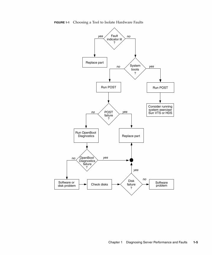
FIGURE 1-1 Choosing a Tool to Isolate Hardware Faults
Systemboots
?
Run POST
yesno
POSTfailure
?
yesno
OpenBoot yes
yes noindicator lit
Fault
?
Diskfailure
?
yes
noSoftwareproblem
no
disk problemSoftware or
system exerciserConsider running
Replace part
Check disks
Run POST
Run OpenBootDiagnostics Replace part
Diagnosticsfailure
?
Sun VTS or HDS
Chapter 1 Diagnosing Server Performance and Faults 1-5
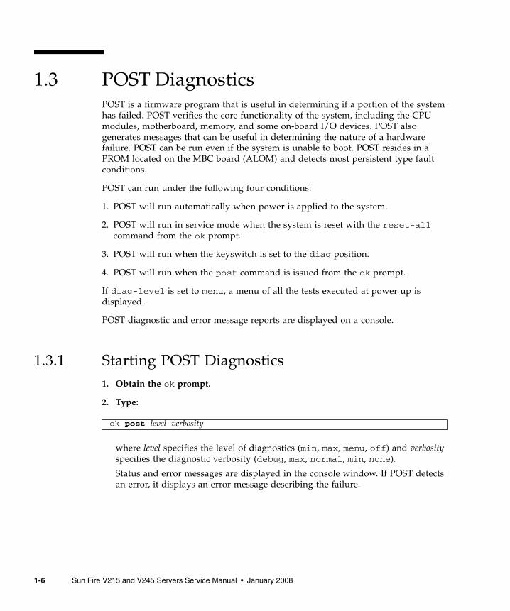
1.3 POST DiagnosticsPOST is a firmware program that is useful in determining if a portion of the systemhas failed. POST verifies the core functionality of the system, including the CPUmodules, motherboard, memory, and some on-board I/O devices. POST alsogenerates messages that can be useful in determining the nature of a hardwarefailure. POST can be run even if the system is unable to boot. POST resides in aPROM located on the MBC board (ALOM) and detects most persistent type faultconditions.
POST can run under the following four conditions:
1. POST will run automatically when power is applied to the system.
2. POST will run in service mode when the system is reset with the reset-allcommand from the ok prompt.
3. POST will run when the keyswitch is set to the diag position.
4. POST will run when the post command is issued from the ok prompt.
If diag-level is set to menu, a menu of all the tests executed at power up isdisplayed.
POST diagnostic and error message reports are displayed on a console.
1.3.1 Starting POST Diagnostics1. Obtain the ok prompt.
2. Type:
where level specifies the level of diagnostics (min, max, menu, off) and verbosityspecifies the diagnostic verbosity (debug, max, normal, min, none).
Status and error messages are displayed in the console window. If POST detectsan error, it displays an error message describing the failure.
ok post level verbosity
1-6 Sun Fire V215 and V245 Servers Service Manual • January 2008

1.3.2 Controlling POST DiagnosticsYou control POST diagnostics (and other aspects of the boot process) by settingOpenBoot configuration variables. Changes to OpenBoot configuration variablesgenerally take effect only after the server is restarted. TABLE 1-2 lists the mostimportant and useful of these variables.
TABLE 1-2 OpenBoot Configuration Variables
OpenBoot ConfigurationVariable Description and Keywords
auto-boot Determines whether the operating system automatically starts boot. Default is true.• true – System automatically boots operating system, once firmware diagnosticsand initialization complete.• false – System remains at ok prompt until you type boot.
diag-level Determines the level or type of diagnostics executed. Default is max.• off – No testing.• min – Only basic tests are run.• max – More extensive tests might be run, depending on the device.• menu – Displays the Diagnostics Engineering Monitor menu.
verbosity Displays notice, warning, error, and fatal messages on the console.• max – Displays detailed progress and informational messages.• normal – Keeps regular output to a minimum.• min – Displays notice, warning, error, and fatal messages.• none – Displays only error and fatal messages.
diag-script Determines which devices are tested by OpenBoot Diagnostics. Default is normal.• none – No devices are tested.• normal – On-board devices are tested.• all – All devices that have self-tests are tested.
Chapter 1 Diagnosing Server Performance and Faults 1-7

1 – POST messages cannot be displayed on a graphics terminal. Messages are sent to TTYA when the output-device is set to screen.
Note – These variables affect OpenBoot Diagnostics tests as well as POSTdiagnostics.
After POST diagnostics have finished running, POST reports back to the OpenBootfirmware the status of each test it has run. Control then reverts back to the OpenBootfirmware code.
If POST diagnostics do not uncover a fault, and the server still does not start up, runOpenBoot Diagnostics tests. See FIGURE 1-1 for additional information.
diag-trigger Determines under what reset conditions, POST/OpenBoot Diagnostics shall beexecuted.• none – Do not run diagnostics on any reset event (requires diag–switch? =false)
• user-reset – User invoked reset• error-reset – When system encounters an error reset event (Red State Exception,
Watchdog, Fatal).• power-on-reset – When power is applied to the system. Default is (power-on-reset, error-reset).
input-device Selects where console input is taken from. Default is ttya.• ttya – From built-in SER MGT port.• ttyb – From built-in general purpose serial port (SER TTYB)• keyboard – From attached keyboard that is part of a graphics terminal.
output-device Selects where diagnostic and other console output is displayed. Default is ttya.• ttya – To built-in SER MGT port.• ttyb – To built-in general purpose serial port (SER TTYB).• screen – To attached screen that is part of a graphics terminal.1
TABLE 1-2 OpenBoot Configuration Variables (Continued)
OpenBoot ConfigurationVariable Description and Keywords
1-8 Sun Fire V215 and V245 Servers Service Manual • January 2008

1.4 OpenBoot DiagnosticsLike POST diagnostics, OpenBoot Diagnostics code is firmware-based and resides inthe OpenBoot PROM.
1.4.1 Starting OpenBoot Diagnostics1. Obtain the ok prompt.
Become superuser, and then type init 0.
2. Type:
This command displays the OpenBoot Diagnostics menu.
Note – If you have a PCI card installed in the server, then additional tests willappear on the obdiag menu.
3. Run an obdiag test. Type:
Where n represents the number corresponding to the test you want to run.
A summary of the tests is available. At the obdiag> prompt, type:
1.4.2 Controlling OpenBoot Diagnostics TestsMost of the OpenBoot configuration variables you use to control POST (seeTABLE 1-2) also affect OpenBoot diagnostics tests.
■ Use the diag-level variable to control the OpenBoot Diagnostics testing level.
■ Use test-args to customize how the tests run.
ok obdiag
obdiag> test n
obdiag> help
Chapter 1 Diagnosing Server Performance and Faults 1-9

By default, test-args is set to contain an empty string. You can modify test-args using one or more of the reserved keywords shown in TABLE 1-3.
If you want to customize the OpenBoot Diagnostics testing, you can set test-argsto a comma-separated list of keywords, as in this example:
1.4.2.1 test and test-all Commands
You can run OpenBoot Diagnostics tests directly from the ok prompt. To do this,type the test command, followed by the full hardware path of the device (or set ofdevices) to be tested. For example:
Note – Knowing how to construct an appropriate hardware device path requiresprecise knowledge of the hardware architecture of the Sun Fire V215 and V245servers.
TABLE 1-3 Keywords for the test-args OpenBoot Configuration Variable
Keyword What It Does
bist Invokes built-in self-test (BIST) on external and peripheral devices
debug Displays all debug messages
iopath Verifies bus and interconnect integrity
loopback Exercises external loopback path for the device
media Verifies external and peripheral device media accessibility
restore Attempts to restore original state of the device if the previousexecution of the test failed
silent Displays only errors rather than the status of each test
subtests Displays main test and each subtest that is called
verbose Displays detailed messages of status of all tests
callers=N Displays backtrace of N callers when an error occurs• callers=0 - displays backtrace of all callers before the error
errors=N Continues executing the test until N errors are encountered• errors=0 - displays all error reports without terminating testing
ok setenv test-args debug,loopback,media
ok test /ebus@1f,464000/serial@2,40
1-10 Sun Fire V215 and V245 Servers Service Manual • January 2008

To customize an individual test, you can use test-args as follows:
This affects only the current test without changing the value of the test-argsOpenBoot configuration variable.
You can test all the devices in the device tree with the test-all command:
If you specify a path argument to test-all, then only the specified device and itschildren are tested. The following example shows the command to test the USB busand all devices with self-tests that are connected to the USB bus:
1.4.2.2 What OpenBoot Diagnostics Error Messages Tell You
OpenBoot diagnostics error messages are reported in a tabular format that contains ashort summary of the problem, the hardware device affected, the subtest that failed,and other diagnostic information. displays an example OpenBoot Diagnostics errormessage.
ok test /ebus@1f,464000/serial@2,40:test-args={verbose,debug}
ok test-all
ok test-all /pci@9,700000/usb@1,3
Testing /ebus@1f,464000/flashprom@0,0
ERROR : FLASHPROM CRC-32 is incorrectSUMMARY : Obs=0x1ea5bc20 Exp=0x5c896226 XOR=0x422cde06 Addr=0xfeb1fffc
DEVICE : /ebus@1f,464000/flashprom@0,0 SUBTEST : selftest MACHINE : Sun Fire V215 SERIAL# : 64196915 DATE : 04/07/2006 23:27:45 GMT CONTR0LS: diag-level=max test-args=
Error: /ebus@1f,464000/flashprom@0,0 selftest failed, return code = 1Selftest at /ebus@1f,464000/flashprom@0,0 (errors=1) .............failedPass:1 (of 1) Errors:1 (of 1) Tests Failed:1 Elapsed Time: 0:0:0:1
Chapter 1 Diagnosing Server Performance and Faults 1-11

1.4.3 OpenBoot Diagnostic CommandsOpenBoot commands that can provide useful diagnostic information are:
■ probe-scsi and probe-scsi-all
■ probe-ide
■ show-devs
1.4.3.1 probe-scsi and probe-scsi-all Commands
The probe-scsi and probe-scsi-all commands diagnose problems withSCSI devices.
Caution – If you use the halt command or the Stop-A key sequence to reach theok prompt and then issue the probe-scsi or probe-scsi-all command, thesyetem might hang.
The probe-scsi command communicates with all SCSI devices connected to on-board SCSI controllers. The probe-scsi-all command additionally accessesdevices connected to any host adapters installed in PCI slots.
For any SCSI device that is connected and active, the probe-scsi and probe-scsi-all commands display its loop ID, host adapter, logical unit number, uniqueWorld Wide Name (WWN), and a device description that includes type andmanufacturer.
The following is example output from the probe-scsi command.
{1} ok probe-scsiMPT Version 1.05, Firmware version 0.03.23.00
Target 0 Unit 0 Disk FUJITSU MAY2073RCSUN72G 0401 143374738Blocks, 73 GB SASAddress 500000e011772152 PhyNum 0Target 1 Unit 0 Disk FUJITSU MAY2073RCSUN72 0401 143374738bLOCKS, 73 gb SASAdress 500000@e0115adf42 PhyNum 1
1-12 Sun Fire V215 and V245 Servers Service Manual • January 2008

The following is example output from the probe-scsi-all command.
1.4.3.2 probe-ide Command
The probe-ide command communicates with all Integrated Drive Electronics (IDE)devices connected to the IDE bus. This bus is the internal system bus for mediadevices such as the optional DVD super-multi drive.
Caution – If you used the halt command or the Stop-A key sequence to reach theok prompt, then issuing the probe-ide command can hang the system.
The following is example output from the probe-ide command.
{1} ok probe-scsi-all/pci@1e,600000/pci@0/pci@a/pci@0/pci@8/scsi@1
MPT Version 1.05 Firmware Version 0.03.23.00
Target 0 Unit 0 Disk FUJITSU MAY2073RCSUN72G 0401 143374738 Blocks,73GB SASAddress 500000e011772152 PhyNum 0Target 1Unit 0 Disk FUJITSUMAY2073RCSUN72G 0401 143374738 Blocks,
73GB SASAddress 500000e0115adf42 PhyNum 1
{1} ok probe-ide Device 0 ( Primary Master ) Removable ATAPI Model: MATSHITADVD-RAM UJ-845S
Device 1 ( Primary Slave ) Not Present
Device 2 ( Secondary Master ) Not Present
Device 3 ( Secondary Slave ) Not Present
Chapter 1 Diagnosing Server Performance and Faults 1-13

1.4.3.3 show-devs Command
The show-devs command lists the hardware device paths for each device in thefirmware device tree. The following shows some example output.
1.4.3.4 Running OpenBoot Commands
1. Halt the system to reach the ok prompt.
How you do this depends on the system’s condition. If possible, warn usersbefore you shut the system down. One method is to become superuser andthen type the init 0 command.
2. Type the appropriate OpenBoot command at the console prompt.
{1} ok show-devs//i2c@1f,530000/ebus@1f,464000/pci@1f,700000/pci@1e,600000/memory-controller@0,0/SUNW,UltraSPARC-IIIi+0,0/virtual-memory/memory@m0,0/aliases/options/openprom/chosen/packages/i2c@1f, 5300000/dimm-spd@0,e2/i2c@1f, 5300000/dimm-spd@0,e0/i2c@1f, 5300000/clock-generator@0,dc/i2c@1f, 5300000/rscrtc@0,d0/i2c@1f, 5300000/hardware-monitor@0,b0/i2c@1f, 5300000/riser-fru-prom@0,a8/i2c@1f, 5300000/idprom@0,a6/i2c@1f, 5300000/nvram,a6
1-14 Sun Fire V215 and V245 Servers Service Manual • January 2008

1.5 Operating System Diagnostic ToolsIf a system passes OpenBoot Diagnostics tests, it normally attempts to boot itsmultiuser operating system. For most Sun systems, this means the Solaris OS. Afterthe server is running in multiuser mode, you have access to the software-baseddiagnostic tools, SunVTS, and Hardware Diagnostic Suite. These tools enable you tomonitor the server, exercise it, and isolate faults.
Note – If you set the auto-boot OpenBoot configuration variable to false, theoperating system does not boot following completion of the firmware-based tests.
In addition to the tools mentioned above, you can refer to error and system messagelog files, and Solaris system information commands.
1.5.1 Error and System Message Log FilesError and other system messages are saved in the /var/adm/messages file.Messages are logged to this file from many sources, including the operating system,the environmental control subsystem, and various software applications.
1.5.2 Solaris System Information CommandsThe following Solaris commands display data that you can use when assessing thecondition of a Sun Fire V215 or V245 server:
■ prtconf
■ prtdiag
■ prtfru
■ psrinfo
■ showrev
This section describes the information that these commands give you. Moreinformation on using these commands is contained in the appropriate man page.
Chapter 1 Diagnosing Server Performance and Faults 1-15

1.5.2.1 prtconf Command
The prtconf command displays the Solaris device tree. This tree includes all of thedevices probed by the OpenBoot firmware, as well as additional devices, likeindividual disks that are exposed to the operating system only. The output ofprtconf also includes the total amount of system memory.
The -p option produces output similar to the OpenBoot show-devs command. Thisoutput lists only those devices that are compiled by the system firmware.
1.5.2.2 prtdiag Command
The prtdiag command displays a table of diagnostic information that summarizesthe status of system components. The display format used by the prtdiagcommand can vary depending on what version of the Solaris OS is running on thesystem.
The verbose option (-v) includes information about the front panel status, diskstatus, fan status, power supplies, hardware revisions, and system temperatures.
In the event of an overtemperature condition, prtdiag reports an error in the Statuscolumn.
If there is a failure of a particular component, prtdiag reports a fault in theappropriate Status column.
System Temperatures (Celsius):-------------------------------DeviceTemperature Status---------------------------------------CPU0 62 OKCPU1 102 ERROR
Fan Status:-----------
Bank RPM Status---- ----- ------CPU0 4166 [NO_FAULT]CPU1 0000 [FAULT]
1-16 Sun Fire V215 and V245 Servers Service Manual • January 2008

1.5.2.3 prtfru Command
The Sun Fire V215 and V245 servers maintain a hierarchical list of all FRUs in thesystem, as well as specific information about various FRUs.
The prtfru command can display this hierarchical list, as well as data contained inthe serial electrically-erasable programmable read-only memory (SEEPROM) deviceslocated on many FRUs.
Data displayed by the prtfru command varies depending on the type of FRU. Ingeneral, it includes:
■ FRU description
■ Manufacturer name and location
■ Part number and serial number
■ Hardware revision levels
1.5.2.4 psrinfo Command
The psrinfo command displays the date and time each CPU came online. With theverbose (-v) option, the command displays additional information about the CPUs,including their clock speed.
1.5.2.5 showrev Command
The showrev command displays revision information for the current hardware andsoftware. When used with the (-p) option, this command displays installedpatches.
1.6 Recent Diagnostic Test ResultsSummaries of the results from the most recent POST and OpenBoot diagnostics testsare saved across power cycles.
Chapter 1 Diagnosing Server Performance and Faults 1-17

1.6.1 Viewing Recent Test Results1. Obtain the ok prompt.
2. Do either of the following:
■ To see a summary of the most recent POST results, type:
■ To see a summary of the most recent OpenBoot Diagnostics test results, type:
This command produces a system-dependent list of hardware components, alongwith an indication of which components passed and which failed POST orOpenBoot diagnostics tests.
1.7 Additional Diagnostic Tests for SpecificDevicesYou can use the probe-scsi, probe-scsi-all, probe-ide, watch-net, andwatch-net-all commands to perform additional diagnostic tests on specificdevices. This section contains procedures for using these commands.
1.7.1 Confirming That the Internal Hard Drives AreActiveThe probe-scsi command transmits an inquiry to SCSI devices connected to thesystem’s internal SCSI interface. If a SCSI device is connected and active, thecommand displays the unit number, device type, and manufacturer name for thatdevice.
Caution – If you use the halt command or the Stop-A key sequence to reach theok prompt and then issue the probe-scsi or probe-scsi-all command, thesystem might hang.
ok show-post-results
ok show-obdiag-results
1-18 Sun Fire V215 and V245 Servers Service Manual • January 2008
1. Obtain the ok prompt.
Become superuser and type init 0
2. Type probe-scsi.
The following is an example of the output from the probe-scsi command.
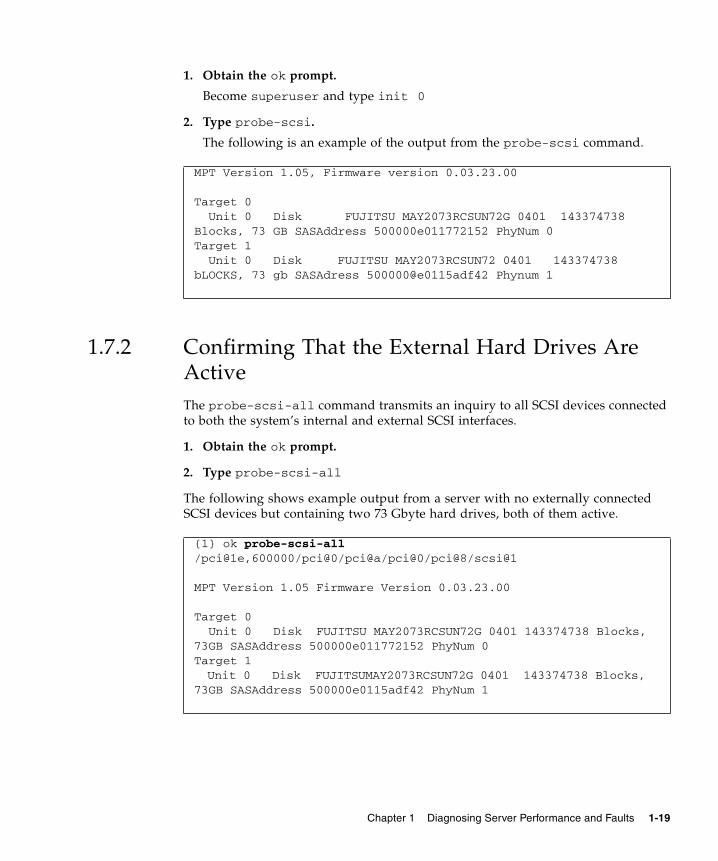
1.7.2 Confirming That the External Hard Drives AreActiveThe probe-scsi-all command transmits an inquiry to all SCSI devices connectedto both the system’s internal and external SCSI interfaces.
1. Obtain the ok prompt.
2. Type probe-scsi-all
The following shows example output from a server with no externally connectedSCSI devices but containing two 73 Gbyte hard drives, both of them active.
MPT Version 1.05, Firmware version 0.03.23.00
Target 0 Unit 0 Disk FUJITSU MAY2073RCSUN72G 0401 143374738Blocks, 73 GB SASAddress 500000e011772152 PhyNum 0Target 1 Unit 0 Disk FUJITSU MAY2073RCSUN72 0401 143374738bLOCKS, 73 gb SASAdress 500000@e0115adf42 Phynum 1
{1} ok probe-scsi-all/pci@1e,600000/pci@0/pci@a/pci@0/pci@8/scsi@1
MPT Version 1.05 Firmware Version 0.03.23.00
Target 0 Unit 0 Disk FUJITSU MAY2073RCSUN72G 0401 143374738 Blocks,73GB SASAddress 500000e011772152 PhyNum 0Target 1Unit 0 Disk FUJITSUMAY2073RCSUN72G 0401 143374738 Blocks,
73GB SASAddress 500000e0115adf42 PhyNum 1
Chapter 1 Diagnosing Server Performance and Faults 1-19

1.7.3 Confirming That the DVD Super-Multi Drive IsConnectedThe probe-ide command transmits an inquiry command to internal and externalIDE devices connected to the system’s on-board IDE interface.
1. Obtain the OK prompt.
2. Type probe-ide.
The following example output shows a optional DVD super-multi drive installed (asDevice 0) and active in a server.
1.7.4 Checking Network Connections on the PrimaryNetworkThe watch-net diagnostics test monitors Ethernet packets on the primary networkinterface. Good packets received by the system are indicated by a period (.). Errorssuch as the framing error and the cyclic redundancy check (CRC) error are indicatedwith an X and an associated error description.
1. Obtain the ok prompt.
2. Type watch-net.
{1} ok probe-ide Device 0 ( Primary Master ) Removable ATAPI Model: MATSHITADVD-RAM UJ-845S
Device 1 ( Primary Slave ) Not Present
Device 2 ( Secondary Master ) Not Present
Device 3 ( Secondary Slave ) Not Present
{1}ok watch-net100Mbps FDX Link upLooking for Ethernet Packets.‘.’ is a Good Packet. ‘X’ is a Bad PacketType any key to stop................................
1-20 Sun Fire V215 and V245 Servers Service Manual • January 2008

1.7.5 Checking Network Connections on AdditionalNetwork InterfacesThe watch-net-all diagnostics test monitors Ethernet packets on the primarynetwork interface and on any additional network interfaces connected to the systemboard. Good packets received by the system are indicated by a period (.). Errors suchas the framing error and the cyclic redundancy check (CRC) error are indicated withan X and an associated error description.
1. Obtain the ok prompt.
Become superuser and type init 0
2. Type watch-net-all at the prompt.
{1}ok watch-net-all/pci@1e,600000/pci@0/pci@a/pci@0/[email protected] FDX Link upLooking for Ethernet Packets‘.’ is a Good Packet. ‘X’ is a Bad PacketType any key to stop................................
Chapter 1 Diagnosing Server Performance and Faults 1-21

1-22 Sun Fire V215 and V245 Servers Service Manual • January 2008

CHAPTER 2
Replacing Hot-Pluggable and Hot-Swappable CRUs
This chapter describes how to replace the hot-swappable and hot-pluggablecustomer replaceable units (CRUs) in the Sun Fire V215 and V245 servers.
The following topics are covered:
■ Section 2.1, “Devices That Are Hot-Pluggable or Hot-Swappable” on page 2-1
■ Section 2.2, “Hot-Plugging a Hard Drive” on page 2-2
■ Section 2.3, “Hot-Swapping a Fan Tray” on page 2-8
■ Section 2.4, “Hot-Swapping a Hard Drive Fan Tray” on page 2-11
■ Section 2.5, “Hot-Swapping a Power Supply” on page 2-14
2.1 Devices That Are Hot-Pluggable or Hot-SwappableHot-pluggable devices are those devices that you can remove and install while theserver is running, but you must perform administrative tasks before or afterinstalling the hardware (for example, mounting a hard drive). In the Sun Fire V215and V245 servers, the following device is hot-pluggable:
■ Hard drives
2-1

Hot-swappable devices are those devices that can be removed and installed whilethe server is running without affecting the rest of the server’s capabilities. In the SunFire V215 and V245 servers the following devices are hot-swappable:
■ Fan trays
■ Hard drive fan tray
■ Power supplies
Note – In Sun Fire V215 and V245 servers, the chassis-mounted hard drives can behot-swappable (depending on how they are configured).
2.2 Hot-Plugging a Hard DriveThe hard drives in the Sun Fire V215 and V245 servers are hot-pluggable, but thiscapability depends on how the hard drives are configured. To hot-plug a drive youmust take the drive offline (to prevent any applications from accessing it, and toremove the logical software links to it) before you can safely remove it.
The following situations inhibit your ability to hot-plug a drive:
■ If the hard drive contains the operating system, and the operating system is notmirrored on another drive.
■ If the hard drive cannot be logically isolated from the online operations of theserver.
If your drive falls into one of these conditions, you must shut the server down beforeyou replace the hard drive. See Section 3.2.2, “Powering Off the Server – ALOMCommand Line” on page 3-4 or Section 3.2.3, “Powering Off the Server – GracefulShutdown” on page 3-5 or Section 3.2.4, “Powering Off the Server – EmergencyShutdown” on page 3-5.
2-2 Sun Fire V215 and V245 Servers Service Manual • January 2008

2.2.1 Removing a Hard DriveRemoving a hard drive from the Sun Fire V215 and V245 servers is a three stepprocess. You must first identify the drive you want to remove, unconfigure thatdrive from the server, and then manually remove the drive from the chassis.
Perform the following process to remove a hard drive:
1. At the Solaris prompt, type the cfgadm -al command to list all drives in thedevice tree, including drives that are not configured. Type:
This command should identify the Ap_id for the hard drive you want to remove.For example, the output should look like:
2. Type the cfgadm -c unconfigure command to unconfigure the disk. Forexample, type:
where c0:dsk/c0t1d1 is the disk that you are trying to unconfigure.
3. Wait until the blue Service Action Allowed indicator lights (FIGURE 2-1).
This indicator helps you to identify which drive is unconfigured and can beremoved.
# cfgadm -al
Ap_id Type Receptacle Occupant Conditionc0 scsi-bus connected configured unknownc0::dsk/c0t0d0 disk connected configured unknownc0::dsk/c0t1d0 disk connected configured unknownusb0/1 unknown empty unconfigured okusb0/2 unknown empty unconfigured okusb0/3 unknown empty unconfigured okusb1/1 unknown empty unconfigured okusb1/2 unknown empty unconfigured okusb1/3 unknown empty unconfigured okusb2/1 unknown empty unconfigured okusb2/2 unknown empty unconfigured okusb2/3 unknown empty unconfigured okusb2/4 unknown empty unconfigured okusb2/5 unknown empty unconfigured okusb2/6 unknown empty unconfigured okusb2/7 unknown empty unconfigured okusb2/8 unknown empty unconfigured ok----------------------------
# cfgadm -c unconfigure c0::dsk/c0t1d1
Chapter 2 Replacing Hot-Pluggable and Hot-Swappable CRUs 2-3

FIGURE 2-1 Locating the Hard Drive Release Button and Latch
4. On the drive you plan to remove, push the hard drive release button(FIGURE 2-1).
The latch opens.
Caution – The latch is not an ejector. Do not bend the latch too far to the left. Doingso can damage the latch.
5. Grasp the latch and pull the drive out of the drive slot.
Latch
Hard drive 1
Hard drive 0
Hard drive release button
Service action allowed indicator
2-4 Sun Fire V215 and V245 Servers Service Manual • January 2008

2.2.2 Installing a Hard DriveInstalling a hard drive into the Sun Fire V215 and V245 servers is a two-step process.You must first install a hard drive into the drive slot that you want to install thedrive in, and then you must configure that drive to the server.
Perform the following process to install a hard drive.
1. If necessary, remove the blank panel from the chassis.
Note – Sun Fire V215 servers might have a single blank panel that covers the harddrive slot. Sun Fire V245 servers might have as many as three blank panels thatcover the unoccupied hard drive slots.
2. Align the replacement drive to the drive slot (FIGURE 2-1).
Hard drives are physically addressed according to the slot in which they areinstalled. If you removed an existing hard drive from a slot in the server, youmust install the replacement drive in the same slot as the drive that wasremoved.
3. Slide the drive into the drive slot until it is fully seated.
4. Close the latch to lock the drive in place.
Chapter 2 Replacing Hot-Pluggable and Hot-Swappable CRUs 2-5
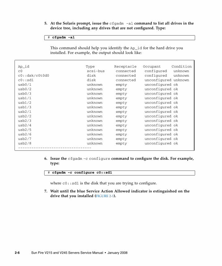
5. At the Solaris prompt, issue the cfgadm -al command to list all drives in thedevice tree, including any drives that are not configured. Type:
This command should help you identify the Ap_id for the hard drive youinstalled. For example, the output should look like:
6. Issue the cfgadm -c configure command to configure the disk. For example,type:
where c0::sd1 is the disk that you are trying to configure.
7. Wait until the blue Service Action Allowed indicator is extinguished on thedrive that you installed (FIGURE 2-1).
# cfgadm -al
Ap_id Type Receptacle Occupant Conditionc0 scsi-bus connected configured unknownc0::dsk/c0t0d0 disk connected configured unknownc0::sd1 disk connected unconfigured unknownusb0/1 unknown empty unconfigured okusb0/2 unknown empty unconfigured okusb0/3 unknown empty unconfigured okusb1/1 unknown empty unconfigured okusb1/2 unknown empty unconfigured okusb1/3 unknown empty unconfigured okusb2/1 unknown empty unconfigured okusb2/2 unknown empty unconfigured okusb2/3 unknown empty unconfigured okusb2/4 unknown empty unconfigured okusb2/5 unknown empty unconfigured okusb2/6 unknown empty unconfigured okusb2/7 unknown empty unconfigured okusb2/8 unknown empty unconfigured ok---------------------------------
# cfgadm -c configure c0::sd1
2-6 Sun Fire V215 and V245 Servers Service Manual • January 2008

8. At the Solaris prompt, issue the cfgadm -al command to list all drives in thedevice tree, including any drives that are not configured. Type:
This command should identify the Ap_id for the hard drive that you installed.The drive you installed should be is configured. For example, the output shouldlook like:
9. Issue the iostat -E command. Type:
The iostat -E command displays information about your system’s installeddevices such as manufacturer, model number, serial number, size, and systemerror statistics.
# cfgadm -al
Ap_Id Type Receptacle Occupant Conditionc0 scsi-bus connected configured unknownc0::dsk/c0t0d0 disk connected configured unknownc0::dsk/c0t1d0 disk connected configured unknownusb0/1 unknown empty unconfigured okusb0/2 unknown empty unconfigured okusb0/3 unknown empty unconfigured okusb1/1 unknown empty unconfigured okusb1/2 unknown empty unconfigured okusb1/3 unknown empty unconfigured okusb2/1 unknown empty unconfigured okusb2/2 unknown empty unconfigured okusb2/3 unknown empty unconfigured okusb2/4 unknown empty unconfigured okusb2/5 unknown empty unconfigured okusb2/6 unknown empty unconfigured okusb2/7 unknown empty unconfigured okusb2/8 unknown empty unconfigured ok----------------------------------
# iostat -E
Chapter 2 Replacing Hot-Pluggable and Hot-Swappable CRUs 2-7

2.3 Hot-Swapping a Fan TraySix hot-swappable fans trays are located under the front cover door.
Two working fan trays are required to provide adequate cooling for the Sun FireV215 and V245 servers. If a fan tray fails, replace it as soon as possible to maximizeserver availability.
The following indicators are lit when a fan tray fault is detected:
■ Front and rear Service Required indicators (FIGURE 2-3) and (FIGURE 2-4).
■ Top Fan indicator on the front of the server (FIGURE 2-3)
■ Fan Fault indicator on the faulty fan (FIGURE 2-2)
If an overtemperature conditions occurs, the front panel CPU Overtemperatureindicator lights and a message is displayed on the console and logged by ALOM.
Tip – You can use the showfault command at the sc> prompt to view the currentfaults.
2.3.1 Removing a Fan Tray1. Gain access to the top of the server where the front cover door for the fan tray
is located (FIGURE 2-2).
2-8 Sun Fire V215 and V245 Servers Service Manual • January 2008

.
You might need to extend the server to a maintenance position. See Section 3.2.5,“Extending the Server to the Maintenance Position – Rackmounted Servers Only” onpage 3-6.
FIGURE 2-2 Removing a Fan Tray
2. Lift the latch, and open the front cover door.
Front cover door
Fan tray (6)
Latch
Handle
Fan Fault indicator (6)
Chapter 2 Replacing Hot-Pluggable and Hot-Swappable CRUs 2-9

3. Identify the faulty fan tray.
A lit Fan Fault indicator on the top of a fan tray indicates that the fan tray isfaulty.
Note – Sun Fire V215 servers have 2 fans installed in each fan tray.
4. Pull up on the fan tray handle until the fan tray is removed from the chassis.
2.3.2 Installing a Fan Tray1. With the front cover door open, install the replacement fan tray into the server
(FIGURE 2-2).
2. Apply firm pressure to fully seat the fan tray.
3. Verify that the Fan Fault indicator on the replaced fan tray is not lit. Alsoverify that the Top Fan indicator, Service Required indicators, and the Locatorindicator/Locator button are not lit (FIGURE 2-2), (FIGURE 2-3) and (FIGURE 2-4).
2-10 Sun Fire V215 and V245 Servers Service Manual • January 2008

FIGURE 2-3 Top Fan, System Required Indicator, Locator Indicators, and Locator Button
FIGURE 2-4 Failure and Service Required Indicators
Note – Each power supply has a failure indicator.
4. Close the front cover door.
5. If necessary, return the server to its normal position in the rack.
2.4 Hot-Swapping a Hard Drive Fan TrayA single hot-swappable fan tray is located under the rear fan tray cover door (SunFire V245 server).
Note – This hot-swappable fan tray is located under the front fan tray cover door onthe Sun Fire V215 server.
If the fan tray fails, replace it as soon as possible to maximize server availability.
Locator indicator/Locator button
Service Required indicator
Top Fan indicator
Service Required indicator
Failure indicator
Chapter 2 Replacing Hot-Pluggable and Hot-Swappable CRUs 2-11

2.4.1 Removing a Hard Drive Fan Tray1. Gain access to the top of the server where the rear cover door for the fan tray is
located (FIGURE 2-5).
The hot-swappable fan tray for the Sun Fire V215 server is located under thefront fan tray cover door.
Note – You might need to extend the server to a maintenance position. SeeSection 3.2.5, “Extending the Server to the Maintenance Position – RackmountedServers Only” on page 3-6.
2. Lift the latch, and open the rear cover door.
3. Verify that the fan tray is faulty.
A lit Fan Fault indicator on the top of a fan tray indicates that the fan tray isfaulty.
Note – The hard drive fan tray has two fans.
4. Pull up on the fan tray handle and remove the fan tray from the chassis.
2-12 Sun Fire V215 and V245 Servers Service Manual • January 2008

FIGURE 2-5 Hard Drive Fan Tray – Sun Fire V245 Server
2.4.2 Installing a Hard Drive Fan Tray1. With the rear cover door open, install the replacement fan tray into the server
(FIGURE 2-5).
The hot-swappable fan tray for the Sun Fire V215 server is located under thefront fan tray cover door.
2. Apply firm pressure to fully seat the fan tray.
3. Verify that the Fan Fault indicator on the replaced fan tray is not lit.
4. Close the rear cover door.
Rear cover door
Rear coverHard drive fan tray
Handle
Fan Fault indicator
Chapter 2 Replacing Hot-Pluggable and Hot-Swappable CRUs 2-13

2.5 Hot-Swapping a Power SupplyThe Sun Fire V245 server’s standard redundant hot-swappable power suppliesenable you to remove and replace a power supply without shutting the server down,provided that the other power supply is online and working.
Note – An optional redundant, hot-swappable power supply is available for the SunFire V215 server.
The following indicators are lit when a power supply fault is detected:
■ Front and rear Service Required indicators (FIGURE 2-3) or (FIGURE 2-4).
■ Rear PS Failure indicator on the bezel of the server (FIGURE 2-4)
■ Failure indicator on the faulty power supply (FIGURE 2-6)
If a power supply fails and you do not have a replacement available, leave the failedpower supply installed to ensure proper air flow in the server.
2.5.1 Removing a Power Supply1. Identify which power supply (0 or 1) requires replacement (FIGURE 2-6).
A lit (amber) failure indicator on a power supply indicates that a failure wasdetected.
Tip – Additional information about power supply status can be found the Sun FireV215 and V245 Getting Started Guide (819-3041).
2-14 Sun Fire V215 and V245 Servers Service Manual • January 2008

FIGURE 2-6 Location of the Power Supplies and Release Latches
2. Gain access to the rear of the server where the faulty power supply is located.
3. Release the cable management arm (CMA) (FIGURE 2-7).
The CMA is located at the rear of the server rack.
a. Press and hold the tab.
b. Rotate the cable management arm out of the way so that you can access thepower supply.
4. Disconnect the power cord from the faulty power supply.
5. Grasp the power supply handle and move the power supply latch to the right.
6. Pull the power supply out of the chassis.
Power supply 0 (PS0)Power supply 1 (PS1)
Failure indicatorRelease Latch (2)
Chapter 2 Replacing Hot-Pluggable and Hot-Swappable CRUs 2-15
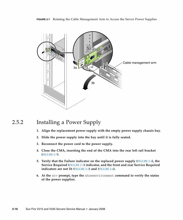
FIGURE 2-7 Rotating the Cable Management Arm to Access the Server Power Supplies
2.5.2 Installing a Power Supply1. Align the replacement power supply with the empty power supply chassis bay.
2. Slide the power supply into the bay until it is fully seated.
3. Reconnect the power cord to the power supply.
4. Close the CMA, inserting the end of the CMA into the rear left rail bracket(FIGURE 2-7).
5. Verify that the Failure indicator on the replaced power supply (FIGURE 2-4), theService Required (FIGURE 2-3) indicator, and the front and rear Service Requiredindicators are not lit (FIGURE 2-3) and (FIGURE 2-4).
6. At the sc> prompt, type the showenvironment command to verify the statusof the power supplies.
Cable management arm
3a
3b
2-16 Sun Fire V215 and V245 Servers Service Manual • January 2008
CHAPTER 3
Replacing Cold-Swappable FRUs
This chapter describes how to replace cold-swappable, field-replaceable units (FRUs)in the Sun Fire V215 and V245 servers.
The following topics are covered:
■ Section 3.1, “Safety Information” on page 3-2
■ Section 3.2, “Procedures for Parts Replacement” on page 3-3
■ Section 3.3, “Removing and Installing FRUs” on page 3-16
■ Section 3.4, “Procedures for Finishing Up” on page 3-60
For a list of CRUs and FRUs, see Section B.1, “Customer and Field-ReplaceableUnits” on page B-1.
Caution – Never attempt to run the server with the covers removed. Hazardousvoltage present.
Caution – Equipment damage possible. The covers must be in place for proper airflow.
3-1
3.1 Safety InformationThis section describes important safety information that you need to know prior toremoving or installing parts in the Sun Fire V215 and V245 servers.
For your protection, observe the following safety precautions when setting up yourequipment:
■ Follow all Sun cautions, warnings, and instructions marked on the equipmentand described in Important Safety Information for Sun Hardware Systems (816-7190).
■ Follow all cautions, warnings, and instructions marked on the equipment anddescribed in the Sun Fire V215 and V245 Compliance and Safety Manual (819-3039).
■ Ensure that the voltage and frequency of your power source match the voltageand frequency inscribed on the equipment’s electrical rating label.
■ Follow the electrostatic discharge safety practices as described in this section.
3.1.1 Safety SymbolsThe following symbols might appear in this document, note their meanings:
Caution – There is a risk of personal injury and or equipment damage. To avoidpersonal injury and equipment damage, follow the instructions.
Caution – Hot surface. Avoid contact. Surfaces are hot and might cause personalinjury if touched.
Caution – Hazardous voltages are present. To reduce the risk of electric shock anddanger to personal health, follow the instructions.
3-2 Sun Fire V215 and V245 Servers Service Manual • January 2008
3.1.2 Electrostatic Discharge Safety MeasuresElectrostatic discharge (ESD) sensitive devices, such as the motherboards, PCI cards,hard drives, and memory cards require special handling.
Caution – Circuit boards and hard drives contain electronic components that areextremely sensitive to static electricity. Ordinary amounts of static electricity fromclothing or the work environment can destroy the components located on theseboards. Do not touch the components along their connector edges.
3.1.2.1 Using an Antistatic Wrist Strap
Wear an antistatic wrist strap and use an antistatic mat when handling componentssuch as hard drive assemblies, circuit boards, or PCI cards. When servicing orremoving server components, attach an antistatic strap to your wrist and then to ametal area on the chassis. Following this practice equalizes the electrical potentialsbetween you and the server.
Note – An antistatic wrist strap is no longer included in the accessory kit for theSun Fire V215 and V245 servers. However, antistatic wrist straps are still includedwith optional components.
3.1.2.2 Using an Antistatic Mat
Place ESD-sensitive components such as motherboards, memory, and other PCBs onan antistatic mat.
3.2 Procedures for Parts ReplacementBefore replacing parts that are not hot-swappable or hot-pluggable inside the SunFire V215 and V245 servers, perform the following procedures:
■ Section 3.2.2, “Powering Off the Server – ALOM Command Line” on page 3-4 orSection 3.2.3, “Powering Off the Server – Graceful Shutdown” on page 3-5 orSection 3.2.4, “Powering Off the Server – Emergency Shutdown” on page 3-5
■ Section 3.2.5, “Extending the Server to the Maintenance Position – RackmountedServers Only” on page 3-6
Chapter 3 Replacing Cold-Swappable FRUs 3-3

■ Section 3.2.7, “Performing Electrostatic Discharge – Antistatic PreventionMeasures” on page 3-9
■ Section 3.2.8, “Removing Power From the Server” on page 3-10
Note – These procedures do not apply to the hot-swappable and hot-pluggabledevices (fans, power supplies, and hard drives) described in Chapter 2.
The procedures that you perform after removing, installing, or repairing the serversare described in Section 3.4, “Procedures for Finishing Up” on page 3-60.
3.2.1 Required ToolsThe Sun Fire V215 and V245 servers can be serviced with the following tools:
■ Antistatic wrist strap
■ Antistatic mat
■ No. 2 Phillips screwdriver
■ No. 1 flat-blade screwdriver (for battery removal)
■ Pen or pencil (to power on server)
3.2.2 Powering Off the Server – ALOM Command Line
Note – Additional information about powering on the server is located in the SunFire V215 and V245 Servers Administration Guide (819-3036).
You can use ALOM to perform a graceful shutdown of the server, to ensure that allof your data is saved, and to ensure that the server is ready for restart.
1. Login as superuser or equivalent.
Depending on the type of problem, you might want to view server status, logfiles, or run diagnostics before you shut down the server. Refer to the Sun FireV215 and V245 Server Administration Guide (819-3036) for log file information.
2. Notify affected users.
Refer to your Solaris system administration documentation for additionalinformation.
3-4 Sun Fire V215 and V245 Servers Service Manual • January 2008

3. Save any open files and quit all running programs.
Refer to your application documentation for specific information on theseprocesses.
4. Shut down the Solaris OS.
Refer to the Solaris system administration documentation for additionalinformation.
5. Switch from the system console to the ALOM sc> prompt by typing the #.(Hash Period) key sequence.
6. At the ALOM sc> prompt, issue the poweroff -fy command.
Note – You can also use the Power button on the front of the server to initiate agraceful server shutdown (See Section 3.2.3, “Powering Off the Server – GracefulShutdown” on page 3-5). This button is recessed to prevent accidental server power-off. Use the tip of a pen to operate this button.
Refer to the Sun Advanced Lights Out Management (ALOM) Administration Guide formore information about the ALOM poweroff command.
3.2.3 Powering Off the Server – Graceful Shutdown● Press and release the Power button.
If necessary, use a pen or pencil to press the Power button.
3.2.4 Powering Off the Server – Emergency Shutdown
Caution – All applications and files will be closed abruptly without saving changes.File system corruption might occur.
● Press and hold the Power button for 4 seconds.
sc> poweroff -fySC Alert: SC Request to Power Off Host Immediately.
Chapter 3 Replacing Cold-Swappable FRUs 3-5

3.2.5 Extending the Server to the Maintenance Position– Rackmounted Servers Only
If the server is installed in a rack with extendable slide rails, use this procedure toextend the server to the maintenance position.
1. (Optional) Issue the following command from the ALOM sc> prompt to locatethe system that requires maintenance (FIGURE 3-1).
Once you have located the server, press the Locator indicator/Locator button toturn it off.
FIGURE 3-1 Locator Indicator/Locator Button
2. Verify that no cables will be damaged or interfere when the server is extended.
Although the cable management arm (CMA) that is supplied with the server ishinged to accommodate extending the server, you should ensure that all cablesand cords are capable of extending.
3. From the front of the server, release the two slide release latches (FIGURE 3-2).
Squeeze the green slide release latches to release the slide rails.
sc> setlocator onLocator indicator is on.
Locator indicator/Locator button
3-6 Sun Fire V215 and V245 Servers Service Manual • January 2008
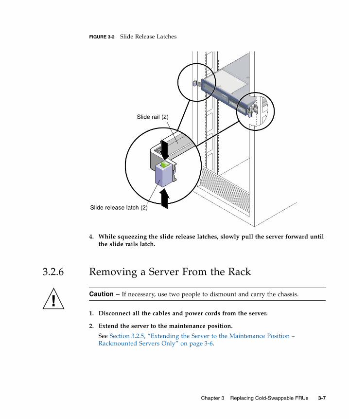
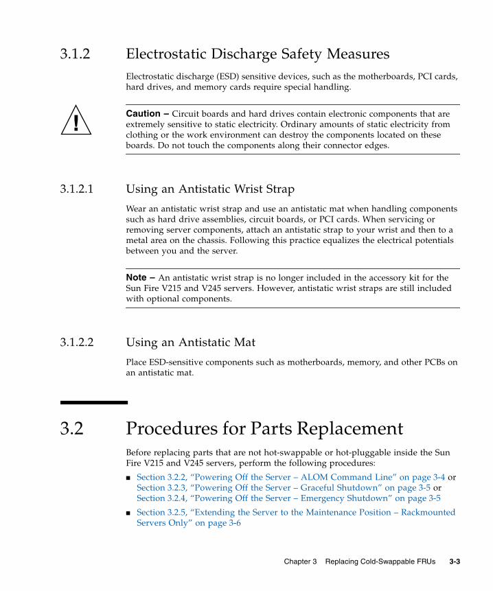
FIGURE 3-2 Slide Release Latches
4. While squeezing the slide release latches, slowly pull the server forward untilthe slide rails latch.
3.2.6 Removing a Server From the Rack
Caution – If necessary, use two people to dismount and carry the chassis.
1. Disconnect all the cables and power cords from the server.
2. Extend the server to the maintenance position.
See Section 3.2.5, “Extending the Server to the Maintenance Position –Rackmounted Servers Only” on page 3-6.
Slide release latch (2)
Slide rail (2)
Chapter 3 Replacing Cold-Swappable FRUs 3-7

3. Press the metal lever that is located on the inner side of the rail to disconnectthe cable management arm (CMA) from the rail assembly (FIGURE 3-3).
The CMA is still attached to the cabinet, but the server chassis is nowdisconnected from the CMA.
FIGURE 3-3 Metal Lever and Cable Management Arm
Caution – If necessary, use two people to dismount and carry the chassis.
4. From the front of the server, pull the release tabs forward and pull the serverforward until it is free of the rack rails (FIGURE 3-4).
A release tab is located on each rail.
Metal lever
Cable management arm
3-8 Sun Fire V215 and V245 Servers Service Manual • January 2008

FIGURE 3-4 Release Tabs and Slide Assembly
5. Set the server on a sturdy work surface.
3.2.7 Performing Electrostatic Discharge – AntistaticPrevention Measures1. Prepare an antistatic surface to set parts on during the removal, installation, or
replacement process.
Place ESD-sensitive components such as the printed circuit boards on anantistatic mat. The following items can be used as an antistatic mat:
■ Antistatic bag used to wrap a Sun replacement part
■ Sun ESD mat, part number 250-1088
■ A disposable ESD mat (shipped with some replacement parts or optional systemcomponents)
2. Attach an antistatic wrist strap.
When servicing or removing server components, attach an antistatic strap to yourwrist and then to a metal area on the chassis.
Slide assembly (2)
Release tab (2)
Chapter 3 Replacing Cold-Swappable FRUs 3-9

3.2.8 Removing Power From the Server
Caution – The system supplies standby power to the circuit boards even when theserver is powered off.
● Disconnect the power cords from the power supplies.
3.2.9 Removing the Rear Cover
Note – Some field-replaceable units (FRUs) require removal of the rear cover.
1. Press and hold the rear cover release button (FIGURE 3-5).
2. Slide the rear cover toward the rear of the server.
Slide the rear cover to the rear about a 0.5 inch (12.7 mm).
3. Remove the rear cover.
Lift up and remove the cover.
Note – If the rear cover is removed before the server is powered down, the Sun FireV215 server will go into Standby mode.
3-10 Sun Fire V215 and V245 Servers Service Manual • January 2008

FIGURE 3-5 Removing the Rear Cover
3.2.10 Removing the Bezel1. Open front cover door (FIGURE 3-6).
Lift the latch and open the front cover door.
Rear cover release button
Rear cover
1
2
3
Chapter 3 Replacing Cold-Swappable FRUs 3-11

FIGURE 3-6 Front Cover, Front Cover Door, and Latch – Sun Fire V245
2. Loosen the captive screw (FIGURE 3-7).
Use a screwdriver to loosen the captive screw. The captive screw secures thebezel to the server.
Front cover
Front cover door
Latch
3-12 Sun Fire V215 and V245 Servers Service Manual • January 2008

FIGURE 3-7 Removing the Bezel From the Server – Sun Fire V245
3. Remove the bezel from the chassis.
The bezel is held in place by a mounting tab and fasteners that secure the bezel tothe chassis.
3.2.11 Removing the Front Cover
Note – Some field-replaceable units (FRUs) require the removal of the front cover.
1. Remove the rear cover.
See Section 3.2.9, “Removing the Rear Cover” on page 3-10.
2. Open the front cover door (FIGURE 3-6).
3. Remove the bezel.
See Section 3.2.10, “Removing the Bezel” on page 3-11.
4. Remove the front cover (FIGURE 3-6).
While holding the front cover door open, slide the front cover forward andremove.
Bezel
Captive screw
Chapter 3 Replacing Cold-Swappable FRUs 3-13

3.2.12 (Sun Fire V245) Removing the Air Baffle
Caution – To prevent the system from overheating, ensure that the air baffle iscorrectly installed before powering on the server.
1. Perform the procedures described in Section 3.2, “Procedures for PartsReplacement” on page 3-3.
2. Remove the rear cover.
See Section 2.2.7, “Removing the Rear Cover” on page 2-9.
3. Lift the handle and remove the air baffle from the server (FIGURE 3-8).
3-14 Sun Fire V215 and V245 Servers Service Manual • January 2008

FIGURE 3-8 Air Baffle, Guide Pins, and Handle – Sun Fire V245
3.2.13 (Sun Fire V245) Installing the Air Baffle
Caution – When the server is in operation, ensure that the air baffle is correctlyinstalled to prevent the system from overheating.
1. Use the guide pins to align and install the air baffle into the chassis(FIGURE 3-8).
Ensure that the air baffle is aligned and fully seated in the chassis.
2. Perform the procedures described in Section 3.4, “Procedures for Finishing Up”on page 3-60.
Guide pin (2)
Handle Air baffle
Chapter 3 Replacing Cold-Swappable FRUs 3-15

3.3 Removing and Installing FRUsThis section provides procedures for replacing the following field replaceable units(FRUs) inside the server chassis:
■ Section 3.3.1, “Removing PCI-E and PCI-X Cards” on page 3-17
■ Section 3.3.2, “Installing PCI-E or PCI-X Cards” on page 3-19
■ Section 3.3.3, “Removing PCI-E and PCI-X Riser Boards” on page 3-20
■ Section 3.3.4, “Installing PCI-E or PCI-X Riser Boards” on page 3-22
■ Section 3.3.5, “Removing DIMMs” on page 3-23
■ Section 3.3.6, “Installing DIMMs” on page 3-26
■ Section 3.3.7, “Removing the Motherboard Assembly” on page 3-28
■ Section 3.3.8, “Installing the Motherboard Assembly” on page 3-34
■ Section 3.3.9, “Removing the Power Distribution Board” on page 3-36
■ Section 3.3.10, “Installing the Power Distribution Board” on page 3-41
■ Section 3.3.11, “Removing the Front Indicator Board” on page 3-43
■ Section 3.3.12, “Installing the Front Indicator Board” on page 3-44
■ Section 3.3.13, “Removing the Fan Tray Connector Boards” on page 3-44
■ Section 3.3.14, “Installing the Fan Tray Connector Boards” on page 3-45
■ Section 3.3.15, “Removing the Front I/O Board” on page 3-46
■ Section 3.3.16, “Installing the Front I/O Board” on page 3-47
■ Section 3.3.17, “Removing the DVD Super-Multi Drive” on page 3-48
■ Section 3.3.18, “Installing the DVD Super-Multi Drive” on page 3-49
■ Section 3.3.19, “Removing the Hard Drive Backplane” on page 3-50
■ Section 3.3.20, “Installing the Hard Drive Backplane” on page 3-52
■ Section 3.3.21, “Removing the Hard Drive Fan Tray” on page 3-53
■ Section 3.3.22, “Installing the Hard Drive Fan Tray” on page 3-54
■ Section 3.3.23, “(Sun Fire V245) Removing the Hard Drive Fan Tray ConnectorBoard” on page 3-55
■ Section 3.3.24, “(Sun Fire V245) Installing the Hard Drive Fan Tray ConnectorBoard” on page 3-56
■ Section 3.3.25, “Removing the Battery” on page 3-57
■ Section 3.3.26, “Installing the Battery” on page 3-58
■ Section 3.3.27, “Removing NVRAM” on page 3-59
■ Section 3.3.28, “Installing NVRAM” on page 3-60
3-16 Sun Fire V215 and V245 Servers Service Manual • January 2008

To locate these FRUs, see Section B.1, “Customer and Field-Replaceable Units” onpage B-1.
Note – Procedures for removing and installing hot-swappable and hot-pluggableCRUs are described in Chapter 2.
3.3.1 Removing PCI-E and PCI-X Cards1. Perform the procedures described in Section 3.2, “Procedures for Parts
Replacement” on page 3-3.
2. Remove the rear cover.
See Section 3.2.9, “Removing the Rear Cover” on page 3-10.
3. (Sun Fire V245) Remove the air baffle.
Removal of a long PCI card might require you to remove the air baffle.
4. Locate the PCI card that you want to remove.
To locate the PCI card slots, refer to FIGURE 3-9 and FIGURE 3-10.
Chapter 3 Replacing Cold-Swappable FRUs 3-17

FIGURE 3-9 Location of PCI-E and PCI-X Slots, and PCI Hold-Down Bracket – Sun FireV215
FIGURE 3-10 Location of PCI-E and PCI-X Slots, and PCI Hold-Down Bracket – Sun FireV245
5. If necessary, make a note of where the PCI card is installed.
Also note the location of any cables for reinstallation later.
6. Release the PCI hold-down bracket (FIGURE 3-9) or (FIGURE 3-10).
Rotate the PCI hold-down bracket 90 degrees so it no longer covers the PCI cardthat you want to remove.
7. Carefully remove the PCI card from the PCI card slot and riser board connector(FIGURE 3-11).
PCI-E slot 0 PCI-X slot 1
PCI hold-down bracket
PCI-E Slot 2
PCI-E Slot 0
PCI-X slot 3
PCI-X slot 1
PCI hold-down bracket
3-18 Sun Fire V215 and V245 Servers Service Manual • January 2008

FIGURE 3-11 Riser Board and PCI Card Connector – Sun Fire V215
8. Place the PCI card on an antistatic mat.
3.3.2 Installing PCI-E or PCI-X Cards1. Unpackage the replacement PCI-E or PCI-X card, and place it on an antistatic
mat.
2. Locate the proper PCI slot for the card you are replacing (FIGURE 3-9 orFIGURE 3-10).
3. If necessary, review the PCI-E and PCI-X card guidelines to plan yourinstallation.
See Section A.2, “PCI-E and PCI-X Card Guidelines” on page A-3 for additionalinformation.
4. Rotate the PCI hold-down bracket 90 degrees so you can install the card.
5. If necessary, remove the filler panel.
6. Insert the PCI card into the slot.
7. Rotate the PCI hold-down bracket 90 degrees to lock the card in place.
8. (Sun Fire V245) If a PCI long card is installed, use the brace from the air baffleto support the card.
PCI card slotRiser board connector
PCI card
Chapter 3 Replacing Cold-Swappable FRUs 3-19
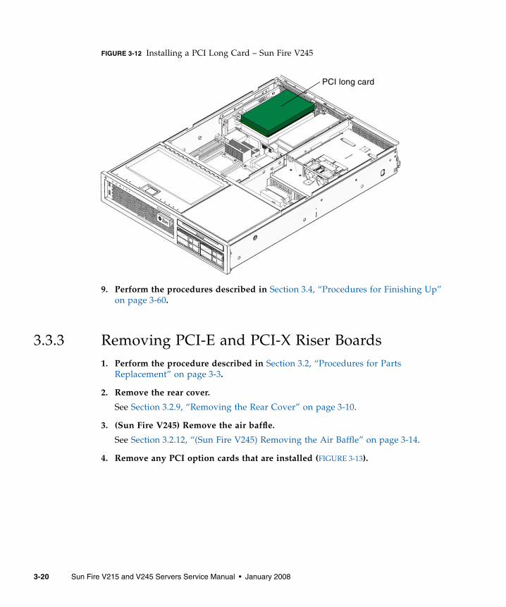
FIGURE 3-12 Installing a PCI Long Card – Sun Fire V245
9. Perform the procedures described in Section 3.4, “Procedures for Finishing Up”on page 3-60.
3.3.3 Removing PCI-E and PCI-X Riser Boards1. Perform the procedure described in Section 3.2, “Procedures for Parts
Replacement” on page 3-3.
2. Remove the rear cover.
See Section 3.2.9, “Removing the Rear Cover” on page 3-10.
3. (Sun Fire V245) Remove the air baffle.
See Section 3.2.12, “(Sun Fire V245) Removing the Air Baffle” on page 3-14.
4. Remove any PCI option cards that are installed (FIGURE 3-13).
PCI long card
3-20 Sun Fire V215 and V245 Servers Service Manual • January 2008
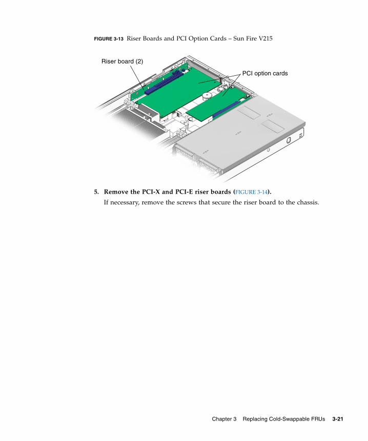
FIGURE 3-13 Riser Boards and PCI Option Cards – Sun Fire V215
5. Remove the PCI-X and PCI-E riser boards (FIGURE 3-14).
If necessary, remove the screws that secure the riser board to the chassis.
Riser board (2)
PCI option cards
Chapter 3 Replacing Cold-Swappable FRUs 3-21

FIGURE 3-14 PCI-E and PCI-X Riser Boards
6. Place the PCI riser boards on an antistatic mat.
3.3.4 Installing PCI-E or PCI-X Riser Boards1. Unpackage the replacement PCI-E or PCI-X card, and place it on an antistatic
mat.
2. Install the PCI-E and PCI-X riser boards in the motherboard connectors(FIGURE 3-14).
If necessary, install the screws that secure the riser board to the chassis.
3. Install the PCI option cards.
See Section 3.3.2, “Installing PCI-E or PCI-X Cards” on page 3-19.
4. (Sun Fire V245) If a PCI long card is installed, use the brace from the air baffleto support the card.
5. Perform the procedures described in Section 3.4, “Procedures for Finishing Up”on page 3-60.
PCI-E riser board
PCI-X riser board
Motherboard connector (2)
3-22 Sun Fire V215 and V245 Servers Service Manual • January 2008

3.3.5 Removing DIMMs
Caution – This procedure requires that you handle components that are sensitive tostatic discharge. This sensitivity can cause the component to fail. To avoid thisproblem, ensure that you follow antistatic practices as described in Section 3.2.7,“Performing Electrostatic Discharge – Antistatic Prevention Measures” on page 3-9.
Caution – Ensure that all power is removed from the server before removing orinstalling DIMMs.
1. Perform the procedures described in Section 3.2, “Procedures for PartsReplacement” on page 3-3.
2. Remove the rear cover.
Section 3.2.9, “Removing the Rear Cover” on page 3-10.
3. Remove any PCI-X or PCI-E cards.
See Section 3.3.1, “Removing PCI-E and PCI-X Cards” on page 3-17.
4. (Sun Fire V245) Remove the air baffle (FIGURE 3-8).
See Section 3.2.12, “(Sun Fire V245) Removing the Air Baffle” on page 3-14.
5. (Sun Fire V215) Remove the motherboard to front I/O board cable (FIGURE 3-20).
6. Locate the DIMMs that you want to replace (See FIGURE 3-15 and TABLE 3-1).
Tip – If you are removing DIMMs as a result of a system error or fault, refer toTABLE 3-1 for additional information.
TABLE 3-1 DIMM Names, Connectors, and Locations
DIMM Name Used in System FaultMessage DIMM Connector DIMM Location
/CHASSIS/MB/P0/B0/D0 J5 DIMM 0
/CHASSIS/MB/P0/B0/D1 J2 DIMM 1
/CHASSIS/MB/P0/B1/D0 J4 DIMM 2
/CHASSIS/MB/P0/B1/D1 J1 DIMM 3
Chapter 3 Replacing Cold-Swappable FRUs 3-23

Tip – Make a note of the DIMM location so that you can install the replacementDIMM in the same location.
Note – For memory configuration information see Section A.1, “DIMM Guidelines”on page A-1.
7. (Sun Fire V215) Remove the screws and air baffles for the DIMMs you want toremove (FIGURE 3-15).
To obtain adequate clearance, it might be necessary to remove the front cover, seeSection 3.2.11, “Removing the Front Cover” on page 3-13.
/CHASSIS/MB/P1/B0/D0 J25 DIMM 4
/CHASSIS/MB/P1/B0/D1 J29 DIMM 5
/CHASSIS/MB/P1/B1/D0 J27 DIMM 6
/CHASSIS/MB/P1/B1/D1 J30 DIMM 7
TABLE 3-1 DIMM Names, Connectors, and Locations (Continued)
DIMM Name Used in System FaultMessage DIMM Connector DIMM Location
3-24 Sun Fire V215 and V245 Servers Service Manual • January 2008

FIGURE 3-15 Removing the Air Baffle – Sun Fire V215
8. Push down on the ejector tabs on each side of the DIMM until the DIMM isreleased (FIGURE 3-16).
Air baffle (2)
Screw (2)
DIMM 0
DIMM 1
DIMM 2
DIMM 3
DIMM 4
DIMM 5
DIMM 6
DIMM 7
Chapter 3 Replacing Cold-Swappable FRUs 3-25

FIGURE 3-16 Removing DIMMs
9. Grasp the top corners of the faulty DIMM and remove it from the server.
10. Place the DIMM on an antistatic mat.
11. Repeat Step 8 through Step 10 until all DIMMs have been removed.
3.3.6 Installing DIMMs
Caution – Ensure that all power is removed from the server before removing orinstalling DIMMs or damage to the DIMMs might occur.
1. Unpackage the replacement DIMMs and place them on an antistatic mat.
Tip – See Section A.1, “DIMM Guidelines” on page A-1 for information aboutconfiguring the DIMMs.
2. Ensure that the ejector tabs are in the open position.
3. Line up the replacement DIMM with the connector (FIGURE 3-16).
Align the DIMM notch with the key in the connector. This ensures that theDIMM is oriented correctly.
Ejector tabs
DIMM Notch
3-26 Sun Fire V215 and V245 Servers Service Manual • January 2008

4. Push the DIMM into the connector until the ejector tabs lock the DIMM inplace.
If the DIMM does not easily seat into the connector, verify that the orientation ofthe DIMM is as shown in FIGURE 3-16. If the orientation is reversed damage to theDIMM might occur.
5. Repeat Step 2 through Step 4 until all replacement DIMMs are installed.
6. (Sun Fire V245) Reinstall the air baffle.
See Section 3.2.13, “(Sun Fire V245) Installing the Air Baffle” on page 3-15.
7. (Sun Fire V215) Reinstall the screws and the air baffles (FIGURE 3-15).
8. (Sun Fire V215) Reinstall the motherboard to front I/O board cable(FIGURE 3-20).
9. Perform the procedures described in Section 3.4, “Procedures for Finishing Up”on page 3-60.
10. Perform the following steps to verify that there are no faults:
a. Set the virtual keyswitch to Diag mode so that POST will run in Servicemode.
b. Issue the poweron command.
c. Switch to the system console to view POST output.
Watch the POST output for possible fault messages. The following output is asign that POST did not detect any faults:
sc> setkeyswitch diag
sc> poweron
sc> console
.
.
.0:0>POST Passed all devices.0:0>0:0>DEMON: (Diagnostics Engineering MONitor)0:0>Select one of the following functions0:0>POST:Return to OBP.0:0>INFO:0:0>POST Passed all devices.0:0>Master set ACK for vbsc runpost command and spin...
Chapter 3 Replacing Cold-Swappable FRUs 3-27

Note – Depending on the configuration of ALOM, POST variables, and whetherPOST detected faults or not, the server might boot, or the system might remain atthe ok prompt. If the system is at the ok prompt, type boot.
d. Issue the Solaris OS fmadm faulty command.
No memory or DIMM faults should be displayed.
3.3.7 Removing the Motherboard Assembly
Caution – This procedure requires that you handle components that are sensitive toelectrostatic discharge. This discharge can cause server components to fail. To avoidthis problem, ensure that you follow the antistatic practices as described inSection 3.2.7, “Performing Electrostatic Discharge – Antistatic Prevention Measures”on page 3-9.
FIGURE 3-17 Motherboard Assembly
1. Perform the procedure described in Section 3.2, “Procedures for PartsReplacement” on page 3-3.
2. If necessary, remove the server from the rack.
See Section 3.2.6, “Removing a Server From the Rack” on page 3-7.
Ensure that you remove all cables as well as the power cords.
# fmadm faulty
3-28 Sun Fire V215 and V245 Servers Service Manual • January 2008

3. Remove the rear cover.
See Section 3.2.9, “Removing the Rear Cover” on page 3-10.
4. Remove the bezel.
Section 3.2.10, “Removing the Bezel” on page 3-11.
5. Remove the front cover.
Section 3.2.11, “Removing the Front Cover” on page 3-13.
6. (Sun Fire V245) Remove the air baffle.
See Section 3.2.12, “(Sun Fire V245) Removing the Air Baffle” on page 3-14.
7. Remove any PCI option cards that are installed.
See Section 3.3.1, “Removing PCI-E and PCI-X Cards” on page 3-17.
8. Remove the PCI-X and PCI-E riser boards (FIGURE 3-18).
FIGURE 3-18 PCI-X and PCI-E Riser Boards – Sun Fire V215
9. (Sun Fire V215) Remove the PCI-X riser board standoff (See FIGURE 3-19 andFIGURE 3-19).
It might be necessary to unlock the PCI-X riser board standoff from the chassis.Press the release and then remove the PCI riser board standoff (FIGURE 3-18).
PCI-E riser boardPCI-X riser board
PCI-X riser board standoff release
Chapter 3 Replacing Cold-Swappable FRUs 3-29

FIGURE 3-19 PCI-X Riser Board Standoff – Sun Fire V215
10. Disconnect the motherboard to front I/O board cable (FIGURE 3-20).
This is the cable between the motherboard and the front I/O board.
PCI-X riser board standoff
3-30 Sun Fire V215 and V245 Servers Service Manual • January 2008

FIGURE 3-20 Motherboard to Front I/O Board Cable
11. (Sun Fire V215) Remove the screws and the air baffles (FIGURE 3-15).
12. If necessary, make note of the memory configuration so that you can reinstallthe memory in the replacement motherboard.
13. Remove all DIMMs.
See Section 3.3.5, “Removing DIMMs” on page 3-23 from the motherboardassembly.
14. Remove NVRAM.
See Section 3.3.27, “Removing NVRAM” on page 3-59.
15. Remove the motherboard/SAS backplane cable connector (FIGURE 3-21).
Motherboard to front I/O board cable
Chapter 3 Replacing Cold-Swappable FRUs 3-31

FIGURE 3-21 Motherboard/SAS Backplane Cable Connector and Screws
16. Using a No. 2 Phillips screwdriver, remove the 11 screws that secure themotherboard assembly to the chassis (FIGURE 3-22).
The two screws that are installed under the motherboard/SAS backplane cableare black in color. The screws connect the motherboard to the power distributionboard through bus bars.
Note – When you reinstall the motherboard, replace the black screws into the samescrew holes.
Motherboard/SAS backplane cable connectorScrew (2) (hidden under cable)
3-32 Sun Fire V215 and V245 Servers Service Manual • January 2008

FIGURE 3-22 Removing the Motherboard Assembly Screws
Bus bar screw (2)
Screw (9)
Chapter 3 Replacing Cold-Swappable FRUs 3-33

17. Using the green handles, slide the motherboard forward and tilt themotherboard assembly to lift it out of the chassis (FIGURE 3-23).
Grab the handles and move the motherboard to the front of the system and lift itout of the chassis.
FIGURE 3-23 Removing the Motherboard Assembly From the Chassis
18. Place the motherboard assembly on an antistatic mat.
3.3.8 Installing the Motherboard Assembly
Caution – This procedure requires that you handle components that are sensitive tostatic discharge. Static discharges can cause the component failures. To avoid thisproblem, ensure that you follow antistatic practices as described in Section 3.2.7,“Performing Electrostatic Discharge – Antistatic Prevention Measures” on page 3-9.
1. Unpackage the replacement motherboard assembly and place it on an antistaticmat.
2. Using the green handles, tilt the motherboard assembly to position it into thechassis (FIGURE 3-24).
When you install the motherboard ensure that you position the board as farforward in the chassis as possible.
Handle (2)
Motherboard
3-34 Sun Fire V215 and V245 Servers Service Manual • January 2008

FIGURE 3-24 Installing the Motherboard Assembly
3. Position the motherboard so that its screw holes align with the chassisstandoffs.
4. Using the green handles, push down firmly and equally while sliding themotherboard to the rear of the chassis.
Tip – After installing the motherboard into the chassis, ensure that the motherboardis correctly seated by gently lifting up on the handles. If the board moves upward,then it is not correctly seated. Also, check for binds and ensure that the indicators,connectors, and ports are correctly aligned at the rear of the server.
5. Install the screws that secure the motherboard to the chassis (FIGURE 3-22).
The two screws that are installed under the motherboard/SAS backplane cableare black in color.
Note – When you reinstall the motherboard, use only the black screws in screwholes that attach the motherboard to the bus bars.
6. Reinstall the motherboard/SAS backplane cable to the motherboard(FIGURE 3-21).
7. Reinstall all DIMMs in the motherboard assembly.
Chapter 3 Replacing Cold-Swappable FRUs 3-35

Tip – Only install the DIMMs in the slots (connectors) from which they wereremoved. See Section 3.3.6, “Installing DIMMs” on page 3-26.
8. Reinstall NVRAM.
See Section 3.3.28, “Installing NVRAM” on page 3-60.
9. (Sun Fire V215) Reinstall the air baffles for the DIMMs and the screws(FIGURE 3-15).
10. Reinstall the motherboard to front I/O board cable (FIGURE 3-20).
Connect the cable between the front I/O board and the motherboard.
11. (Sun Fire V215) Reinstall the PCI-X riser board standoff (FIGURE 3-19).
12. Reinstall the PCI-E and PCI-X riser boards (FIGURE 3-18).
13. Reinstall any PCI option cards that were removed.
See Section 3.3.2, “Installing PCI-E or PCI-X Cards” on page 3-19.
14. (Sun Fire V245) Reinstall the air baffle.
See Section 3.2.13, “(Sun Fire V245) Installing the Air Baffle” on page 3-15.
15. Perform the procedures described in Section 3.4, “Procedures for Finishing Up”on page 3-60.
3.3.9 Removing the Power Distribution Board1. Perform the procedures described in Section 3.2, “Procedures for Parts
Replacement” on page 3-3.
Caution – The system supplies power to the power distribution board even whenthe server is powered off. To avoid personal injury or damage to the server, youmust disconnect power cords before servicing the power distribution board.
2. Remove the rear cover.
See Section 3.2.9, “Removing the Rear Cover” on page 3-10.
3. Remove the bezel.
See Section 3.2.10, “Removing the Bezel” on page 3-11.
4. Remove the front cover.
See Section 3.2.11, “Removing the Front Cover” on page 3-13.
3-36 Sun Fire V215 and V245 Servers Service Manual • January 2008

5. Remove the power supplies from the chassis (FIGURE 3-25).
The power supplies are attached to the power distribution board. Push the powersupply latch to the right and pull the power supply out a few inches to disengage itfrom the power distribution board.
FIGURE 3-25 Power Supply Release Latches – Sun Fire V245
6. Remove the motherboard/SAS backplane cable.
a. (Sun Fire V245 and pre-January 2008 V215 servers) Remove the upper andlower cable retainers (FIGURE 3-24).
The retainers protect the optional DVD super-multi drive, hard drivebackplane, and motherboard cable from damage.
Power supply release latch (2)
Chapter 3 Replacing Cold-Swappable FRUs 3-37

FIGURE 3-26 Upper and Lower Cable Retainers and Motherboard/SAS Backplane Cable
b. (January 2008 V215 servers) Remove the following components(FIGURE 3-27):
■ Two screws on motherboard under the cable
■ FT5 fan
■ Interior screw for metal support bracket
■ Exterior screws under the support bracket
■ Metal support bracket from between backplane cable and upper cable holder
■ Upper and lower cable holder
Upper cable retainer
Lower cable retainer
Motherboard/SAS backplane cableScrew (2) (hidden under cable)
3-38 Sun Fire V215 and V245 Servers Service Manual • January 2008

FIGURE 3-27 Sun Fire V215 (January 2008) Support Bracket Removal
7. Disconnect the motherboard/SAS backplane cable from the power distributionboard, hard drive backplane board, motherboard, and if necessary, the optionalDVD super-multi drive (FIGURE 3-28).
Motherboard/SAS backplane cable
Upper backplane cable holder
FT5 fanLower backplane cable holder
Support bracketInterior support bracket screw
Exterior support bracket screws
Chapter 3 Replacing Cold-Swappable FRUs 3-39

FIGURE 3-28 Motherboard/SAS Backplane Cable Routing
8. Disconnect the cable from connector J6 on the power distribution board(FIGURE 3-39).
9. Remove the hard drive fan tray.
See Section 3.3.21, “Removing the Hard Drive Fan Tray” on page 3-53.
10. Remove the two screws that attach the hard drive fan cage to the chassis of theserver.
11. Remove the hard drive fan tray cage.
12. Remove the three screws that secure the power distribution board to thechassis (FIGURE 3-29).
Motherboard/SAS backplane cable
Motherboard
Power distribution board
DVD super-multi drive
Hard drive backplane
3-40 Sun Fire V215 and V245 Servers Service Manual • January 2008

FIGURE 3-29 Removing the Power Distribution Board
13. Slide the power distribution board toward the front of the chassis and removeit.
14. Place the power distribution board on an antistatic mat.
3.3.10 Installing the Power Distribution Board
Caution – The system supplies power to the power distribution board even whenthe server is powered off. To avoid personal injury or damage to the server, youmust disconnect all power cords before servicing the power distribution board.
1. Unpackage the replacement power distribution board and place it on anantistatic mat.
2. Loosely fit the power distribution board onto the locator pins in the chassisand slide the board toward the rear of the chassis (FIGURE 3-29).
3. Reinstall the power distribution board and the three screws.
4. Reconnect the cable from connector J1 on the hard drive fan tray connectorboard to connector J6 on the power distribution board.
Screws (3)
Connector J6
Power distribution board
Chapter 3 Replacing Cold-Swappable FRUs 3-41

5. Reinstall the hard drive fan tray cage.
6. Reinstall the two screws that attach the hard drive fan cage to the chassis of theserver.
7. Reinstall the hard drive fan tray.
See Section 3.3.22, “Installing the Hard Drive Fan Tray” on page 3-54.
8. Reinstall the motherboard/SAS backplane cable (FIGURE 3-26).
Connect the motherboard/SAS backplane cable to:
■ Optional DVD super-multi drive (if installed)
■ Hard drive backplane
■ Power distribution board
■ Motherboard
9. (January 2008 V215 servers) Reinstall the support bracket components(FIGURE 3-27):
■ Two screws on motherboard under the cable
■ FT5 fan
■ Interior screw for metal support bracket
■ Exterior screws under the support bracket
■ Metal support bracket from between backplane cable and upper cable holder
■ Upper and lower cable holder
10. (Sun Fire V245 and pre-January 2008 V215 servers) Reinstall the upper andlower cable retainers for the motherboard/SAS backplane cable (FIGURE 3-26).
11. Reinstall the power supplies.
See Section 2.5.2, “Installing a Power Supply” on page 2-16.
12. Perform the procedures described in Section 3.4, “Procedures for Finishing Up”on page 3-60.
Note – After replacing the power distribution board and powering on the system,you must run the setcsn command on an ALOM console to electronically input thechassis serial number.
3-42 Sun Fire V215 and V245 Servers Service Manual • January 2008

3.3.11 Removing the Front Indicator Board1. Perform the procedures described in Section 3.2, “Procedures for Parts
Replacement” on page 3-3.
2. Remove the rear cover.
See Section 3.2.9, “Removing the Rear Cover” on page 3-10.
3. Remove the bezel.
See Section 3.2.10, “Removing the Bezel” on page 3-11.
4. Remove the front cover.
See Section 3.2.11, “Removing the Front Cover” on page 3-13.
5. Remove the two screws that secure the front indicator board to the chassis(FIGURE 3-30).
FIGURE 3-30 Removing the Front Indicator Board
6. Remove the front indicator board.
Slide the board to the right to disconnect it from the front I/O board.
7. Place front indicator board on an antistatic mat.
Screw (2)
Front indicator board
Chapter 3 Replacing Cold-Swappable FRUs 3-43

3.3.12 Installing the Front Indicator Board1. Unpackage the replacement front indicator board and place it on an antistatic
mat.
2. Install the front indicator board in the chassis (FIGURE 3-30).
Slide the board to the left to connect it to the front I/O board.
3. Secure the front indicator board to the chassis using two Philips screws.
4. Perform the procedures described in Section 3.4, “Procedures for Finishing Up”on page 3-60.
3.3.13 Removing the Fan Tray Connector Boards1. Perform the procedures described in Section 3.2, “Procedures for Parts
Replacement” on page 3-3.
2. Remove the fan trays.
Only remove the fan trays that are necessary to remove the defective fan trayconnector board.
See Section 2.3.1, “Removing a Fan Tray” on page 2-8).
Note – Sun Fire V215 servers have two fans for each fan tray.
3. Remove the Phillips screws that secure the fan tray connector boards to thechassis (FIGURE 3-31).
3-44 Sun Fire V215 and V245 Servers Service Manual • January 2008

FIGURE 3-31 Removing the Fan Tray Connector Board
4. Slide the fan tray connector boards to the right to disengage them from thefront I/O board.
5. Remove the fan tray connector boards and place the boards on an antistaticmat.
3.3.14 Installing the Fan Tray Connector Boards1. Unpackage the replacement fan tray connector boards and place the boards on
an antistatic mat.
2. Lower the boards into place and slide the boards to the left to plug the boardsinto the front I/O board.
3. Secure the boards to the chassis with the Phillips screws.
Screw (2)Fan tray connector board (2)
Front I/O board
Chapter 3 Replacing Cold-Swappable FRUs 3-45

4. Reinstall the fan trays.
See Section 2.3.2, “Installing a Fan Tray” on page 2-10.
Note – Sun Fire V215 servers have two fans for each fan tray.
5. Perform the procedures described in Section 3.4, “Procedures for Finishing Up”on page 3-60.
3.3.15 Removing the Front I/O Board1. Perform the procedures described in Section 3.2, “Procedures for Parts
Replacement” on page 3-3.
2. Remove the rear cover.
See Section 3.2.9, “Removing the Rear Cover” on page 3-10.
3. (Sun Fire V245) Remove the air baffle.
See Section 3.2.12, “(Sun Fire V245) Removing the Air Baffle” on page 3-14.
4. Remove the bezel.
See Section 3.2.10, “Removing the Bezel” on page 3-11.
5. Remove the front cover.
See Section 3.2.11, “Removing the Front Cover” on page 3-13.
6. Remove the motherboard to front I/O board cable (FIGURE 3-20).
This cable connects the front I/O and motherboards.
7. Remove all six fan trays.
See Section FIGURE 2-2, “Removing a Fan Tray” on page 2-9.
8. Remove the fan tray connector boards from the front I/O board.
See Section 3.3.13, “Removing the Fan Tray Connector Boards” on page 3-44.
9. Remove the front indicator board.
See Section 3.3.11, “Removing the Front Indicator Board” on page 3-43.
10. Remove the front I/O board (FIGURE 3-32).
3-46 Sun Fire V215 and V245 Servers Service Manual • January 2008
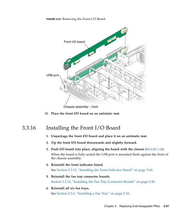
FIGURE 3-32 Removing the Front I/O Board
11. Place the front I/O board on an antistatic mat.
3.3.16 Installing the Front I/O Board1. Unpackage the front I/O board and place it on an antistatic mat.
2. Tip the front I/O board downwards and slightly forward.
3. Push I/O board into place, aligning the board with the chassis (FIGURE 3-32).
When the board is fully seated the USB port is mounted flush against the front ofthe chassis assembly.
4. Reinstall the front indicator board.
See Section 3.3.12, “Installing the Front Indicator Board” on page 3-44.
5. Reinstall the fan tray connector boards.
Section 3.3.14, “Installing the Fan Tray Connector Boards” on page 3-45.
6. Reinstall all six fan trays.
See Section 2.3.2, “Installing a Fan Tray” on page 2-10.
Front I/O board
USB port
Chassis assembly – front
Chapter 3 Replacing Cold-Swappable FRUs 3-47

7. Reinstall the motherboard to front I/O board cable (FIGURE 3-20).
8. (Sun Fire V245) Reinstall the air baffle.
See Section 3.2.13, “(Sun Fire V245) Installing the Air Baffle” on page 3-15.
9. Perform the procedures described in Section 3.4, “Procedures for Finishing Up”on page 3-60.
3.3.17 Removing the DVD Super-Multi Drive1. Perform the procedures described in Section 3.2, “Procedures for Parts
Replacement” on page 3-3.
2. Remove the rear cover.
See Section 3.2.9, “Removing the Rear Cover” on page 3-10.
3. Remove the bezel.
Section 3.2.10, “Removing the Bezel” on page 3-11.
4. Remove the front cover.
Section 3.2.11, “Removing the Front Cover” on page 3-13.
5. Remove the upper cable retainer (FIGURE 3-33).
3-48 Sun Fire V215 and V245 Servers Service Manual • January 2008

FIGURE 3-33 Upper Cable Retainer, Motherboard/SAS Backplane Cable, DVD Super-MultiDrive, and Spring Latch
6. Disconnect the motherboard/SAS backplane cable.
Disconnect the motherboard/SAS backplane cable at the connector for the DVDsuper-multi drive. It is not necessary to disconnect the motherboard/SASbackplane cable from the hard drive backplane or the power distribution board.
7. Push the spring latch to the right and hold (FIGURE 3-33).
Release the spring latch that secures the DVD super-multi drive to the hard drivecage assembly.
8. Remove the DVD super-multi drive from the chassis.
Push the drive from the rear and remove it from the chassis.
9. Place the drive on an antistatic mat.
3.3.18 Installing the DVD Super-Multi Drive1. Unpackage the DVD super-multi drive and place it on an antistatic mat.
2. Slide the DVD super-multi drive into the front of the chassis until it seats.
Upper cable retainer
Motherboard/SAS backplane cable
DVD super-multi drive
Spring latch
Screw
Hard drive cage assembly
Chapter 3 Replacing Cold-Swappable FRUs 3-49

3. Connect the motherboard/SAS backplane cable to the DVD super-multi drive(FIGURE 3-33).
4. Install the upper cable retainer.
5. Perform the procedures described in Section 3.4, “Procedures for Finishing Up”on page 3-60.
3.3.19 Removing the Hard Drive Backplane1. Perform the procedures described in Section 3.2, “Procedures for Parts
Replacement” on page 3-3.
2. Remove the optional DVD super-multi drive from the chassis (if installed).
See Section 3.3.17, “Removing the DVD Super-Multi Drive” on page 3-48.
3. Remove all hard drives from the chassis.
See Section 2.2.1, “Removing a Hard Drive” on page 2-3.
Note – Identify the slot in which each hard drive belongs for later installation intothe chassis.
4. Remove the upper and lower cable retainers (FIGURE 3-21).
5. Disconnect the motherboard/SAS backplane cable from the hard drivebackplane (FIGURE 3-28).
6. (Sun Fire V215) Remove the screw that secures the secures the hard driveassembly and DVD super-multi drive to the chassis (FIGURE 3-34).
7. (Sun Fire V215) Remove the hard drive cage assembly.
The DVD super-multi drive and hard drive assembly are housed together in thehard drive cage assembly. When the screw is removed you can remove harddrive cage assembly from the chassis.
8. (Sun Fire V215) Remove the three screws that secure the SAS drive backplaneto the hard drive card cage.
9. (Sun Fire V215) Place the hard drive backplane on an antistatic mat.
3-50 Sun Fire V215 and V245 Servers Service Manual • January 2008

FIGURE 3-34 Removing the Hard Drive Backplane – Sun Fire V215
10. (Sun Fire V245) Remove the three screws that secure the hard drive backplaneto the hard drive card cage assembly (FIGURE 3-35).
FIGURE 3-35 Removing the Hard Drive Backplane – Sun Fire V245
11. (Sun Fire V245) Remove the hard drive backplane from the chassis and place iton an antistatic mat.
Hard drive backplane
Screw (3)
Hard drive card cage assemblyScrew
Chapter 3 Replacing Cold-Swappable FRUs 3-51

3.3.20 Installing the Hard Drive Backplane1. Unpackage the replacement hard drive backplane and place it on an antistatic
mat.
2. (Sun Fire V215) Install the three screws that secure the hard drive backplane tothe hard drive card cage assembly.
Note – Do not tighten the screws until all three are installed.
3. (Sun Fire V215) Install the DVD super-multi drive and hard drive assemblyinto the chassis.
The DVD super-multi drive and hard drive assembly are housed together in thehard drive cage assembly.
4. (Sun Fire V215) Install the screw that secures the hard drive cage assembly tothe chassis (FIGURE 3-33).
5. (Sun Fire V245) Use three screws to attach the hard drive backplane to the harddrive cage assembly (FIGURE 3-34).
Note – Do not tighten the screws until all three of them are in place.
6. Reinstall the DVD super-multi drive (if necessary).
See Section 3.3.18, “Installing the DVD Super-Multi Drive” on page 3-49.
7. Connect the motherboard/SAS backplane cable to the replacement hard drivebackplane.
8. If necessary, connect the motherboard/SAS backplane cable to the DVD super-multi drive.
9. Install the upper and lower cable retainers (FIGURE 3-21).
10. Reinstall all hard drives in the slots from which you removed them.
If necessary, see Section 2.2.2, “Installing a Hard Drive” on page 2-5.
11. Perform the procedures described in Section 3.4, “Procedures for Finishing Up”on page 3-60.
3-52 Sun Fire V215 and V245 Servers Service Manual • January 2008

3.3.21 Removing the Hard Drive Fan Tray1. Open the rear cover door (FIGURE 3-36).
Lift the rear cover door latch.
FIGURE 3-36 Opening the Rear Cover Door – Sun Fire V245
2. Remove the hard drive fan tray (FIGURE 3-37).
Note – The hard drive fan tray has two fans.
Rear cover door
Rear coverLatch
Chapter 3 Replacing Cold-Swappable FRUs 3-53

FIGURE 3-37 Hard Drive Fan Tray – Sun Fire V245
3.3.22 Installing the Hard Drive Fan Tray1. Unpackage the replacement hard drive fan tray and place it on an antistatic
mat.
2. Open the rear cover door (FIGURE 3-36).
Lift the latch to open the door.
3. Install the hard drive fan tray (FIGURE 3-37).
Ensure that the fan connector securely mates with the connector on the fan trayconnector board.
Note – The hard drive fan tray has two fans.
4. Close the rear cover door.
5. Perform the procedures described in Section 3.4, “Procedures for Finishing Up”on page 3-60.
Hard drive fan tray
3-54 Sun Fire V215 and V245 Servers Service Manual • January 2008

3.3.23 (Sun Fire V245) Removing the Hard Drive FanTray Connector Board1. Perform the procedures described in Section 3.2, “Procedures for Parts
Replacement” on page 3-3.
2. Remove the rear cover.
Section 3.2.9, “Removing the Rear Cover” on page 3-10.
3. Remove the hard drive fan tray.
See Section 3.3.21, “Removing the Hard Drive Fan Tray” on page 3-53.
FIGURE 3-38 Hard Drive Fan Tray Cage and Screws
4. Remove the two screws (FIGURE 3-38).
These screws attach the fan tray cage to the chassis of the server.
5. Remove the hard drive fan tray cage.
6. Disconnect the cable from connector J1 (FIGURE 3-39).
This cable connects connector J1 on the hard drive fan tray connector board toconnector J6 on the power distribution board.
Screw (2)
Hard drive fan tray cage
Chapter 3 Replacing Cold-Swappable FRUs 3-55
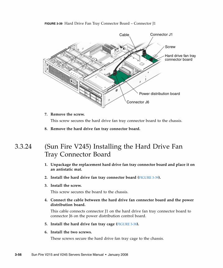
FIGURE 3-39 Hard Drive Fan Tray Connector Board – Connector J1
7. Remove the screw.
This screw secures the hard drive fan tray connector board to the chassis.
8. Remove the hard drive fan tray connector board.
3.3.24 (Sun Fire V245) Installing the Hard Drive FanTray Connector Board1. Unpackage the replacement hard drive fan tray connector board and place it on
an antistatic mat.
2. Install the hard drive fan tray connector board (FIGURE 3-39).
3. Install the screw.
This screw secures the board to the chassis.
4. Connect the cable between the hard drive fan connector board and the powerdistribution board.
This cable connects connector J1 on the hard drive fan tray connector board toconnector J6 on the power distribution control board.
5. Install the hard drive fan tray cage (FIGURE 3-38).
6. Install the two screws.
These screws secure the hard drive fan tray cage to the chassis.
Connector J1
Hard drive fan tray
Power distribution board
Screw
connector board
Cable
Connector J6
3-56 Sun Fire V215 and V245 Servers Service Manual • January 2008

7. Install the hard drive fan tray.
See Section 3.3.22, “Installing the Hard Drive Fan Tray” on page 3-54.
8. Perform the procedures described in Section 3.4, “Procedures for Finishing Up”on page 3-60.
3.3.25 Removing the Battery1. Perform the procedures described in Section 3.2, “Procedures for Parts
Replacement” on page 3-3.
2. Remove the rear cover.
See Section 3.2.9, “Removing the Rear Cover” on page 3-10.
3. If necessary, remove any PCI or PCI-X cards.
See Section 3.3.1, “Removing PCI-E and PCI-X Cards” on page 3-17.
4. Remove the plastic insulator from the heat sinks.
5. (Sun Fire V245) Remove the air baffle.
See Section 3.2.12, “(Sun Fire V245) Removing the Air Baffle” on page 3-14.
6. Using a small (No. 1 flat-blade) screwdriver, press the latch and remove thebattery from the motherboard (FIGURE 3-40).
Chapter 3 Replacing Cold-Swappable FRUs 3-57
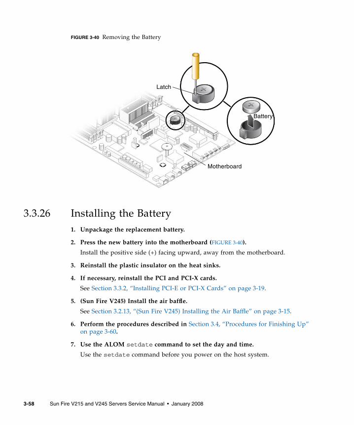
FIGURE 3-40 Removing the Battery
3.3.26 Installing the Battery1. Unpackage the replacement battery.
2. Press the new battery into the motherboard (FIGURE 3-40).
Install the positive side (+) facing upward, away from the motherboard.
3. Reinstall the plastic insulator on the heat sinks.
4. If necessary, reinstall the PCI and PCI-X cards.
See Section 3.3.2, “Installing PCI-E or PCI-X Cards” on page 3-19.
5. (Sun Fire V245) Install the air baffle.
See Section 3.2.13, “(Sun Fire V245) Installing the Air Baffle” on page 3-15.
6. Perform the procedures described in Section 3.4, “Procedures for Finishing Up”on page 3-60.
7. Use the ALOM setdate command to set the day and time.
Use the setdate command before you power on the host system.
Motherboard
Battery
Latch
3-58 Sun Fire V215 and V245 Servers Service Manual • January 2008

3.3.27 Removing NVRAM1. Perform the procedures described in Section 3.2, “Procedures for Parts
Replacement” on page 3-3.
2. Remove the rear cover.
See Section 3.2.9, “Removing the Rear Cover” on page 3-10.
3. If necessary, remove the PCI and PCI-X cards.
See Section 3.3.1, “Removing PCI-E and PCI-X Cards” on page 3-17.
4. Remove the plastic insulator for the heat sinks.
5. (Sun Fire V245) Remove the air baffle.
See Section 3.2.12, “(Sun Fire V245) Removing the Air Baffle” on page 3-14.
6. Locate the NVRAM (FIGURE 3-41).
FIGURE 3-41 Removing NVRAM
7. Pull the NVRAM straight up from the connector.
NVRAM and the NVRAM connector are keyed.
Note – The server will not function correctly without NVRAM installed.
Key
NVRAMNVRAM connector
Chapter 3 Replacing Cold-Swappable FRUs 3-59

3.3.28 Installing NVRAM1. Unpackage the replacement NVRAM and set it on an antistatic mat.
2. Locate the NVRAM connector (FIGURE 3-41).
3. Align the NVRAM module with the NVRAM connector.
Note – NVRAM and the NVRAM connector are keyed.
4. Press the NVRAM down until it seats.
5. Reinstall the plastic insulator for the heat sinks.
6. If necessary, reinstall the PCI and PCI-X cards.
See Section 3.3.2, “Installing PCI-E or PCI-X Cards” on page 3-19.
7. (Sun Fire V245) Install the air baffle.
See Section 3.2.13, “(Sun Fire V245) Installing the Air Baffle” on page 3-15.
8. Perform the procedures described in Section 3.4, “Procedures for Finishing Up”on page 3-60.
3.4 Procedures for Finishing Up
3.4.1 Installing the Front Cover and BezelIf you removed the front cover or bezel perform these steps:
1. Open the front cover door.
Lift the latch.
2. Install the front cover. (FIGURE 3-43).
(Sun Fire V245) The interlock switch is actuated when the front cover is installed.
3. Slide the front cover to the rear until it seats.
4. Position the bezel on the front of the chassis and snap it into place(FIGURE 3-42).
3-60 Sun Fire V215 and V245 Servers Service Manual • January 2008

FIGURE 3-42 Installing the Bezel
5. Tighten the captive screw to secure the bezel to the chassis.
6. Close the front cover door.
Bezel
Captive screw
Chapter 3 Replacing Cold-Swappable FRUs 3-61

FIGURE 3-43 Installing the Front Cover – Sun Fire V245 Server
Note – The interlock switch for the Sun Fire V215 servers is actuated when the rearcover is installed.
3.4.2 Installing the Rear CoverIf you removed the rear cover, perform these steps:
1. Place the rear cover on the chassis.
Set the cover down so that it hangs over the rear of the server by about an inch(25.4 mm).
Caution – When installing the rear cover do not damage the interlock switch (SunFire V215 and V245 servers).
2. Slide the rear cover forward until it seats (FIGURE 3-44).
Note – The interlock switch for the Sun Fire V215 and V245 servers is actuatedwhen the rear cover is installed.
Interlock switch
Front cover
Front cover door
3-62 Sun Fire V215 and V245 Servers Service Manual • January 2008

FIGURE 3-44 Installing the Rear Cover – Sun Fire V215 server
3.4.3 Reinstalling the Server in the RackIf you removed the server chassis from the rack, perform these steps.
Caution – The servers are heavy. Two people might be required to carry the chassisand install it in the rack.
1. On the rack, ensure that the slide rails are extended.
2. Place the ends of the chassis mounting brackets into the slide rails(FIGURE 3-45).
Interlock switch
Rear cover
Chapter 3 Replacing Cold-Swappable FRUs 3-63

FIGURE 3-45 Returning the Server to the Rack
3. Slide the server into the rack until the brackets lock into place.
The server is now in the extended maintenance position.
Chassis mounting bracket
Slide rail (2)
3-64 Sun Fire V215 and V245 Servers Service Manual • January 2008

3.4.4 Returning the Server to the Normal Rack PositionIf you extended the server to the maintenance position, use this procedure to returnthe server to the normal rack position.
1. Release the slide rails from the fully extended position by pushing the releasetabs on the side of each rail (FIGURE 3-46).
FIGURE 3-46 Release Tabs – Rails
2. While pushing on the release tabs, slowly push the server into the rack.
Ensure that the cables do not get in the way.
3. Reconnect the cable management arm (CMA) into the back of the railassembly:
Note – Refer to the Sun Fire V215 and V245 Server Installation Guide for detailedCMA installation instructions.
a. Insert the smaller extension into the clip located at the end of the mountingbracket (FIGURE 3-47).
Rail assembly (2)
Release tab (2)
Chapter 3 Replacing Cold-Swappable FRUs 3-65

FIGURE 3-47 Installing the Cable Management Arm (CMA)
b. Plug the CMA rail extension into the end of the left rail assembly.
The tab at the front of the rail extension clicks into place.
4. Reconnect the cables to the back of the server.
If the CMA is in the way, disconnect the left CMA release and swing the CMAopen.
5. Reconnect all cables that were removed from the rear of the server.
3.4.5 Applying Power to the Server● Reconnect both power cords to the power supplies.
Note – As soon as the power cords are connected, standby power is applied.Depending on the configuration of the firmware, the system might boot.
Clip
CMA rail extension
Cable management arm
3-66 Sun Fire V215 and V245 Servers Service Manual • January 2008
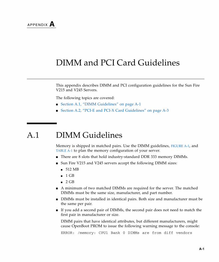
APPENDIX A
DIMM and PCI Card Guidelines
This appendix describes DIMM and PCI configuration guidelines for the Sun FireV215 and V245 Servers.
The following topics are covered:
■ Section A.1, “DIMM Guidelines” on page A-1
■ Section A.2, “PCI-E and PCI-X Card Guidelines” on page A-3
A.1 DIMM GuidelinesMemory is shipped in matched pairs. Use the DIMM guidelines, FIGURE A-1, andTABLE A-1 to plan the memory configuration of your server.
■ There are 8 slots that hold industry-standard DDR 333 memory DIMMs.
■ Sun Fire V215 and V245 servers accept the following DIMM sizes:
■ 512 MB
■ 1 GB
■ 2 GB
■ A minimum of two matched DIMMs are required for the server. The matchedDIMMs must be the same size, manufacturer, and part number.
■ DIMMs must be installed in identical pairs. Both size and manufacturer must bethe same per pair.
■ If you add a second pair of DIMMs, the second pair does not need to match thefirst pair in manufacturer or size.
DIMM pairs that have identical attributes, but different manufacturers, mightcause OpenBoot PROM to issue the following warning message to the console:
ERROR: /memory: CPU1 Bank 0 DIMMs are from diff vendors
A-1

This condition will disable autoboot. However, the DIMMs will still be used. Ifyou encounter this error message, you can boot the server manually.
FIGURE A-1 DIMM Layout
DIMM 0
DIMM 1DIMM 2
DIMM 3
DIMM 4
DIMM 5DIMM 6
DIMM 7
A-2 Sun Fire V215 and V245 Servers Service Manual • January 2008

Note – DIMM names in messages are displayed with the full name such as/MB/P0/B0/D0/.
A.2 PCI-E and PCI-X Card GuidelinesThe PCI expansion system is configured using a variety of riser cards. With therelease of new optional riser cards in October 2007, the guidelines have beenupdated.
The following guidelines now apply for the Sun Fire V215 server:
TABLE A-1 DIMM Name, DIMM Number, DIMM Connector, and Connector Color
DIMM Name DIMM Number DIMM Connector Connector Color
Rank 0 /MB/P0/B0/D0 DIMM 0 J5 Blue
(1 or 2 CPUs) /MB/P0/B0/D1 DIMM 1 J2 Blue
/MB/P0/B1/D0 DIMM 2 J4 Black
/MB/P0/B1/D1 DIMM 3 J1 Black
Rank 1 /MB/P1/B0/D0 DIMM 4 J25 Blue
(2 CPUs) /MB/P1/B0/D1 DIMM 5 J29 Blue
/MB/P1/B1/D0 DIMM 6 J27 Black
/MB/P1/B1/D1 DIMM 7 J30 Black
TABLE 0-1 PCI Card Guidelines for the Sun Fire V215 Server
Riser Type Dimensions Comments
1UXXL (left side) PCI-X (slot 1) Full height, half length\
\ Low-profile cards fit with appropriate full-height faceplate.
133 MHz
1UEEL (left side) PCI-E (slot 1*)
* If you add a 1U or 2U PCI-E riser card, you must remove the PCI-X riser card. The removal results in the loss of available slots forPCI-X option cards.
Full height, half length\
Low profile, half lengthLane x8Lane x8, slot x16
1UEER (right side) PCI-E (slot 0) Low profile, half lengthd
d 1UEER is factory installed in all systems.
Lane x8, slot x16
Appendix A DIMM and PCI Card Guidelines A-3

The following guidelines now apply for the Sun Fire V245 server:
You can add only one riser card to the server. If you add the XVR-2500 graphicsadapter, you must use the PCI-E riser card assembly that converts all of the PCI-XI/O slots to PCI-E slots. After installation, the I/O subsystem will be entirely PCI-Ebased (that is, no PCI-X slots will be available). The XVR-2500 graphics adapter andany PCI-X adapter, including the serial, asynchronous adapter (SAI/P), are mutuallyexclusive within the same system.
TABLE A-2 PCI Card Guidelines for the Sun Fire V245 Server
Riser Type Dimensions Comments
2UEXL (left side) PCI-X (upper slot 3)PCI-X (lower slot 1)
Full height, full lengthd
Full height, half lengthd
d Low-profile cards fit with appropriate full-height faceplate.
133 MHz133 MHz
2UEEL* (left side)
* If you add a 1U or 2U PCI-E riser card, you must remove the PCI-X riser card. The removal results in the loss of available slots forPCI-X option cards.
PCI-E (upper slot 3)PCI-E (lower slot 1)
Full height, full lengthd
Full height, half lengthdLane x8, slot x16Lane x8, slot x16
2UEER\ (right side)
\ 2UEER is factory installed in all systems.
PCI-E (upper slot 2)PCI-E (lower slot 0)
Low profile, half lengthLow profile, half length
Lane x4, slot x16Lane x4, slot x16
A-4 Sun Fire V215 and V245 Servers Service Manual • January 2008

Appendix A DIMM and PCI Card Guidelines A-5

APPENDIX B
Customer and Field-ReplaceableUnits
This appendix describes the location customer and field-replacable units within theSun Fire V215 and V245 Servers.
B.1 Customer and Field-Replaceable UnitsFIGURE B-1, FIGURE B-2, and TABLE B-1 illustrates and lists the locations of thecustomer (CRUs) and field-replaceable units (FRUs) in the Sun Fire V215 and V245servers.
B-1

FIGURE B-1 Customer and Field-Replaceable Units, Part 1 of 2
2
3
4
5
6
7
10
13
14
16
B-2 Sun Fire V215 and V245 Servers Service Manual • January 2008
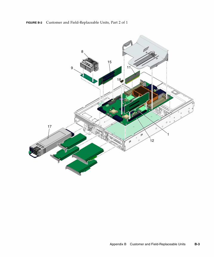
FIGURE B-2 Customer and Field-Replaceable Units, Part 2 of 1
8
9 11
12
15
17
18
1
Appendix B Customer and Field-Replaceable Units B-3

TABLE B-1 Sun Fire V215 and V245 Servers – CRU and FRU List
Item No. CRU or FRU Name and Description Removal Instructions Installation Instructions
1 Lithium battery Section 3.3.25, “Removingthe Battery” on page 3-57.
Section 3.3.26, “Installing theBattery” on page 3-58.
2 Optional DVD super-multi drive Section 3.3.17, “Removingthe DVD Super-MultiDrive” on page 3-48.
Section 3.3.18, “Installing theDVD Super-Multi Drive” onpage 3-49.
3 Hard drive backplane
The backplane board that contains theMolex connector for interfacing to 2.5inch SAS or SATA drives.
Section 3.3.19, “Removingthe Hard Drive Backplane”on page 3-50.
Section 3.3.20, “Installing theHard Drive Backplane” onpage 3-52.
4 Fan tray connector boardHouses the power connectors for thefan assemblies.
Section 3.3.13, “Removingthe Fan Tray ConnectorBoards” on page 3-44.
Section 3.3.14, “Installing theFan Tray Connector Boards”on page 3-45.
5 Fan tray
Fans trays 0, 1, 2, 3, 4, and 5
Section 2.3.1, “Removing aFan Tray” on page 2-8.
Section 2.3.2, “Installing aFan Tray” on page 2-10.
6 Front I/O board Section 3.3.15, “Removingthe Front I/O Board” onpage 3-46.
Section 3.3.16, “Installing theFront I/O Board” onpage 3-47.
7 Front indicator boardContains the circuitry and indicatorsthat are displayed on the bezel of thesystem.
Section 3.3.11, “Removingthe Front Indicator Board”on page 3-43.
Section 3.3.12, “Installing theFront Indicator Board” onpage 3-44.
8 Hard drive fan tray (2) Section 3.3.21, “Removingthe Hard Drive Fan Tray”on page 3-53.
Section 3.3.22, “Installing theHard Drive Fan Tray” onpage 3-54.
9 Hard drive fan tray connector board
Driver board for hard drive fan tray,Sun Fire V245 only
Section 3.3.23, “(Sun FireV245) Removing the HardDrive Fan Tray ConnectorBoard” on page 3-55.
Section 3.3.24, “(Sun FireV245) Installing the HardDrive Fan Tray ConnectorBoard” on page 3-56.
10 Hard drives
SAS or SATA hard drives
Section 2.2.1, “Removing aHard Drive” on page 2-3.
Section 2.2.2, “Installing aHard Drive” on page 2-5.
B-4 Sun Fire V215 and V245 Servers Service Manual • January 2008

11 DIMMs
Can be ordered in the following sizes:• 512 MB• 1 GB• 2 GB• 4 GB
Section 3.3.5, “RemovingDIMMs” on page 3-23.
Section 3.3.6, “InstallingDIMMs” on page 3-26.
12 Motherboard
The motherboard assembly is a singleFRU consisting of one or moreUltraSPARCTM IIIi+ CPU processors.
Section 3.3.7, “Removingthe MotherboardAssembly” on page 3-28.
Section 3.3.8, “Installing theMotherboard Assembly” onpage 3-34.
13 Motherboard – front I/O board cable
Interface between the motherboardand the front I/O board
See FIGURE 3-20.
14 Motherboard/SAS backplane cable
Interface cable between themotherboard and the hard drivebackplane and the optional DVDsuper-multi drive
See FIGURE 3-21.
15 PCI-E andPCI-X riser boards
Section 3.3.3, “RemovingPCI-E and PCI-X RiserBoards” on page 3-20.
Section 3.3.4, “Installing PCI-E or PCI-X Riser Boards” onpage 3-22.
16 Power distribution board (PDB)
Provides a 12 VDC power connectionbetween the power supplies and otherboards.
Section 3.3.9, “Removingthe Power DistributionBoard” on page 3-36.
Section 3.3.10, “Installing thePower Distribution Board”on page 3-41.
17 Power supply (PS)
The power supplies provide 3.3 VDCstandby power at @ 3 Amps and 12VDC at 45 Amps.
Section 2.5.1, “Removing aPower Supply” onpage 2-14.
Section 2.5.2, “Installing aPower Supply” on page 2-16.
18 NVRAM Section 3.3.27, “RemovingNVRAM” on page 3-59.
Section 3.3.28, “InstallingNVRAM” on page 3-60.
TABLE B-1 Sun Fire V215 and V245 Servers – CRU and FRU List (Continued)
Item No. CRU or FRU Name and Description Removal Instructions Installation Instructions
Appendix B Customer and Field-Replaceable Units B-5

B-6 Sun Fire V215 and V245 Servers Service Manual • January 2008

Index
Symbols/var/adm/messages file, 1-15
AALOM POST variables, 3-28ALOM prompt, 3-5antistatic mat, 3-3antistatic wrist strap, 3-3auto-boot? variable, 1-7
Bbattery, B-4BIST, See built-in self-testbuilt-in self-test, test-args variable, 1-10
Ccable
motherboard/front I/O board, B-5motherboard/SAS backplane, 3-35, B-5
cable management arm, 2-15central processing unit, See CPUchassis mounting brackets, 3-63clock speed (CPU), 1-17command
cfgadm -al, 2-3, 2-6, 2-7cfgadm -c, 2-3, 2-6fmadm faulty, 3-28poweroff, 3-5poweron, 3-27set keyswitch, 3-27setcsn, 3-42
setdate, 3-58setlocator, 3-6showenvironment, 2-16showfault, 2-8
common procedures finishing up, 3-60common procedures parts replacement, 3-3compliance and safety manual, 3-2CPU, displaying information about, 1-17CRU, 2-1CRUs and FRUs, B-1
Ddevice paths, hardware, 1-10, 1-14device tree, Solaris, displaying, 1-16diag-level variable, 1-7diag-level variable, 1-7, 1-9diagnostic tools, summary, 1-2diagnostics, POST, 1-6diag-script variable, 1-7diag-trigger, 1-8DIMM
connector numbers, 3-23guidelines, A-1layout, A-2locations, 3-23name, 3-23rank, A-3size, B-5
DIMM messages, 3-23DIMMs, B-5DVD super-multi drive, B-4
Index-1

Eejector tabs, 3-25electrostatic discharge, 3-3emergency shutdown, 3-5error messages
OpenBoot Diagnostics, 1-11OpenBoot Diagnostics tests, 1-11
ESD, 3-9
Ffan connector board, B-4Fan Fault indicator, 2-8fan tray, B-4fan tray connector board, 3-44, 3-45front cover door, 3-13front fan tray cover door, 2-11, 2-13front I/O board, B-4front indicator board, B-4front LED board, B-4FRU
contents of IDPROM, 1-17hardware revision level, 1-17hierarchical list of, 1-17manufacturer, 1-17part number, 1-17
Ggraceful shutdown, 3-4, 3-5
Hhard drive, B-4
addressing, 2-5backplane, B-4cage assembly, 3-50fan tray, B-4fan tray board, B-4release button, 2-4
hard drive fan tray, B-4hardware device paths, 1-10, 1-14hardware revision, displaying with showrev, 1-17host adapter (probe-scsi), 1-12hot-pluggable, 2-1hot-pluggable devices, 2-1hot-plugging, hard drive, 2-2hot-swappable, 2-1
hot-swappable devices, 2-2hot-swapping
fan tray, 2-8hard drive fan tray, 2-11power supply, 2-14
IIDE bus, 1-13important safety information, 3-2indicator
blue Service Action Required, 2-3, 2-6failure, 2-11, 2-14Fan Fault, 2-8Locator, 2-10rear power supply failure, 2-14Service Required, 2-10, 2-14, 2-15Top Fan, 2-10
input-device variable, 1-8installing
DIMMs, 3-26DVD drive, 3-49fan tray, 2-10fan tray connector boards, 3-45front cover and bezel, 3-60front I/O board, 3-47front indicator board, 3-44hard drive, 2-5hard drive backplane, 3-52hard drive fan tray, 2-13motherboard assembly, 3-34NVRAM, 3-60PCI-E and PCI-X cards, 3-19PCI-E and PCI-X riser boards, 3-22power distribution board, 3-41power supply, 2-16
Integrated Drive Electronics, See IDE businterlock switch, 3-62
Llatch, 2-4
power supply, 2-15slide rail, 3-6
location of hard drives, 2-4locator button, 2-11Locator indicator/Locator button, 2-10log files, 1-15logical unit number (probe-scsi), 1-12
Index-2 Sun Fire V215 and V245 Servers Service Manual • January 2008
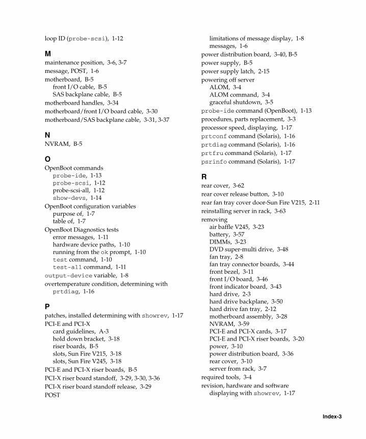
loop ID (probe-scsi), 1-12
Mmaintenance position, 3-6, 3-7message, POST, 1-6motherboard, B-5
front I/O cable, B-5SAS backplane cable, B-5
motherboard handles, 3-34motherboard/front I/O board cable, 3-30motherboard/SAS backplane cable, 3-31, 3-37
NNVRAM, B-5
OOpenBoot commands
probe-ide, 1-13probe-scsi, 1-12probe-scsi-all, 1-12show-devs, 1-14
OpenBoot configuration variablespurpose of, 1-7table of, 1-7
OpenBoot Diagnostics testserror messages, 1-11hardware device paths, 1-10running from the ok prompt, 1-10test command, 1-10test-all command, 1-11
output-device variable, 1-8overtemperature condition, determining with
prtdiag, 1-16
Ppatches, installed determining with showrev, 1-17PCI-E and PCI-X
card guidelines, A-3hold down bracket, 3-18riser boards, B-5slots, Sun Fire V215, 3-18slots, Sun Fire V245, 3-18
PCI-E and PCI-X riser boards, B-5PCI-X riser board standoff, 3-29, 3-30, 3-36PCI-X riser board standoff release, 3-29POST
limitations of message display, 1-8messages, 1-6
power distribution board, 3-40, B-5power supply, B-5power supply latch, 2-15powering off server
ALOM, 3-4ALOM command, 3-4graceful shutdown, 3-5
probe-ide command (OpenBoot), 1-13procedures, parts replacement, 3-3processor speed, displaying, 1-17prtconf command (Solaris), 1-16prtdiag command (Solaris), 1-16prtfru command (Solaris), 1-17psrinfo command (Solaris), 1-17
Rrear cover, 3-62rear cover release button, 3-10rear fan tray cover door-Sun Fire V215, 2-11reinstalling server in rack, 3-63removing
air baffle V245, 3-23battery, 3-57DIMMs, 3-23DVD super-multi drive, 3-48fan tray, 2-8fan tray connector boards, 3-44front bezel, 3-11front I/O board, 3-46front indicator board, 3-43hard drive, 2-3hard drive backplane, 3-50hard drive fan tray, 2-12motherboard assembly, 3-28NVRAM, 3-59PCI-E and PCI-X cards, 3-17PCI-E and PCI-X riser boards, 3-20power, 3-10power distribution board, 3-36rear cover, 3-10server from rack, 3-7
required tools, 3-4revision, hardware and software
displaying with showrev, 1-17
Index-3

riser boards, 3-21
Ssafety symbols, 3-2SAS drive backplane, 3-51SCSI devices, diagnosing problems, 1-12SEEPROM, B-5Service Required indicator, 2-8show-devs command (OpenBoot), 1-14showrev command (Solaris), 1-17software revision, displaying with showrev, 1-17Solaris commands
prtconf, 1-16prtdiag, 1-16prtfru, 1-17psrinfo, 1-17showrev, 1-17
spring latch, 3-49Sun Fire V215 air baffle, 3-24system configuration card, 1-6system memory, determining amount, 1-16
Ttest command (OpenBoot Diagnostics tests), 1-10test-all command (OpenBoot Diagnostics
tests), 1-11test-args variable, 1-10
keywords, 1-10Top Fan indicator, 2-8, 2-10
UUniversal Serial Bus devices, running OpenBoot
Diagnostics self-tests, 1-11upper and lower cable retainers, 3-37, 3-40, 3-42
WWorld Wide Name (probe-scsi), 1-12
Index-4 Sun Fire V215 and V245 Servers Service Manual • January 2008


![Sun ONE Directory Server 5.2 Administration Guide · Sun, Sun Microsystems, le logo Sun, Java, Solaris, SunTone, Sun[tm] ONE, The Network is the Computer, ... 6 Sun ONE Directory](https://img.pdfslide.us/doc/110x75/5b30b9877f8b9ad76e8e62cc/sun-one-directory-server-52-administration-guide-sun-sun-microsystems-le.jpg)