Embed Size (px)
Citation preview

1
INSTALLATION INSTRUCTIONSFORM #1478SUM REV 2/14/08
SUMMIT RACING STREET & STRIPBOOST TIMING MASTER
MULTI-SPARK DIGITAL CD IGNITIONPart No. SUM-850604
For applications triggered by points, Mallory Electronic Ignition Distributor (all models), original equipment electronic ignition amplifiers and magnetic trigger pulses (magnetic pickup distributor or crank trigger ignition).Optional adapters are available for easy connection to early model Delco/GM HEI Systems, late model GMHEI/EST Systems, Ford TFI Systems, and OEM magnetic pickup (non-computer; Ford DuraSpark, GM HEI andMopar/Chrysler Electronic Systems).
NOTE: Summit Racing Street & Strip BTM Digital CD Ignition Controls are not compatible with distributorlesssystems or positive ground applications. The RPM Limiter in the Ignition Controls will not work properly withodd-fire or semi-even fire V6 applications.
Parts included in this kit:1 Summit Racing Street & Strip Digital CD Ignition Control 1 Ignition Control Harness 1 2-Bar MAP Sensor2 Terminal Connectors 1 Bypass Connector4 Cable Ties
2 Spade Terminals8 Ring Terminals, 1/4"1 Ring Terminal, 3/8"5 Spade Receptacle Terminals4 10-32 Screws4 10-32 Nuts with Lockwashers
WARNING: DO NOT USE NON-SUPPRESSOR SPARK PLUG WIRES.
KEEP ALL IGNITION SYSTEM WIRES AS FAR FROM SPARK PLUG WIRES AS POSSIBLE.
CONTENTS
General Information ....................................................2Ignition Ballast Resistor/Loom Resistance Wire................2Standard Ignition Bypass (Bypass Connector)...................2Ignition Coils..........................................................2Fuel Injection .........................................................2Spark Plug Wires.....................................................2Spark Plug Gaps......................................................2Electric Welding ......................................................2External RPM LimitersSummit Tach Adapters ..............................................2
Mounting Procedure ....................................................2Mounting to a Flat Surface Without Brackets....................2Mounting to a Flat Surface with Shock Mounts .................2
Wiring Procedure........................................................3Wiring Method using Adapters and Harnesses..................3GM HEI Systems/coil-in-cap with OEM module)..............3-4Late Model GM HEI/EST Systems (external coil) .............3-5Ford TFI Systems ..................................................3-4Ford DuraSpark Systems (non-computer type,
without module).................................................5-6
Early Model GM HEI Systems (non-computer type,without module)................................................6, 8
Mopar/Chrysler Corp. Electronic Systems(non-computer type, without module) ......................6, 9
Wiring Method Without Adapters .....................................7Breaker Point Systems...........................................7, 9Summit Racing Street & Strip Digital CD Ignition, Mallory UNILITE® Distributors,Magnetic Breakerless Distributors or Electronic Advance Distributors (3-wire/red, brown, green) ....................................................7, 10For OEM Electronic Systems with modules/amplifiers
(Chrysler, Ford, and import)................................7, 10Magnetic Pickup Trigger Pulses (magnetic pickup
distributors or crank trigger ignition) .....................7, 10
Top Panel Operation and Features ..................................11RPM Limiter Operation ...............................................11Bypass Connector......................................................11Warranty.................................................................12

2
GENERAL INFORMATION
Not for marine use. The RPM limiter in this unit is not recommended as anengine speed governor. The use of the RPM limiters is not recommended for applications equipped with a catalytic converter. Similarly, forcing engine RPM pastthe RPM limiter continuously for long sustained intervals can cause fuel build up inthe exhaust system that may adversely affect your application. The RPM limitingsystems will not work properly with odd-fire V6 applications.
Ignition Ballast Resistor/Loom Resistance WireThe performance of the Summit Racing Street & Strip BTM Digital CD IgnitionControl is not affected by the presence of the factory ignition resistors or ignitionballast resistors in the wire from the ignition switch.
Standard Ignition Bypass (Bypass Connector)The Bypass Connector (supplied) fits into the Ignition Control Harness to convertback to standard ignition. If you use the Bypass Connector, use ignition ballastresistors designed for your vehicle’s distributor and coil (see diagrams for moreinformation). This bypass method does not work with magnetic pickup distributoror crank trigger ignition. Racing Applications: It is not necessary to install ignitionballast resistors. However, do not use the Bypass Connector until the ignition ballast resistors are installed in the wire from the ignition switch.
Ignition CoilsRecommended coil is SUM-850500.
Fuel InjectionSome fuel injection systems need a voltage spike signal from the ignition coilbefore they will operate properly. This signal changes once the ignition control isinstalled. The Summit Fuel Injection and Tachometer Adapters Part Nos. SUM-850511 and SUM-850512 supply the proper signal to the vehicle computer tooperate the fuel injection system. Installation procedure and diagrams are suppliedwith these adapters.
Spark Plug WiresYOU MUST USE suppression type (carbon core, spiral core, suppression core)spark plug wire. We recommend spiral core ignition wire, such as Summit RacingStreet & Strip Ignition Wire. Suppression type spark plug wires prevent false triggering and possible premature ignition or accessory failures. DO NOT USE solidcore (copper core; stainless steel core) spark plug wire with any electronic ignitionsystem or accessory.
Spark Plug GapsFor street applications, use your engine manufacturer’s specifications. For racingapplications, start with your engine manufacturer’s specifications, then experimentwith, and closely monitor, various gaps to achieve maximum performance.
Electric WeldingUnplug the Ignition Control Harness from the Summit Racing Street & Strip BTMDigital CD Ignition Control and unplug any distributor harnesses (if possible) beforeany welding is done on the vehicle.
MOUNTING PROCEDURE
Step 1Disconnect the battery (–) cable to cut power to the system. Computerized vehi-cles: Disconnect the battery (–) cable and let the vehicle sit overnight before pro-ceeding. This allows the computer to calibrate for the new ignition.
Step 2Select a convenient location to mount the ignition. Keep the unit away from hotengine components or extreme heat such as the exhaust system and manifolds.Also, keep it away from moving devices, such as fans, belts and linkages. Thelocation must be dry. Moisture will damage components inside the unit.
Step 3Choose one mounting method listed for mounting the ignition control (3a or 3b).(3a) Mounting to a flat surface• Center punch the mounting pattern on the mounting surface using the housing
holes to mark locations for drilling mounting holes. Drill holes using a 7/32" drill bit.
• Hold the ignition control in position over the mounting holes.
• From the backside of the mounting surface, insert the 10-32 screws with lockwashers through the mounting holes and attach with the 10-32 nuts supplied.
(3b) Mounting to a flat surface with shock mounts • Center punch the mounting pattern on the mounting surface using the housing
holes to mark locations for drilling mounting holes. Drill holes using a 7/32" drill bit.
• Install the shock mounts into the side flanges of the ignition control and tightennuts. Hold the unit in position where it will be mounted.
• From the backside of the mounting surface, insert the 10-32 nuts with lockwashers onto the shock mount studs. Tighten each nut until snug.
FIGURE 1

3
FIGURE 2
BASIC WIRING PROCEDURE
Step 1
Refer to Figure 2Ensure that your vehicle is equipped with a ground cable between the engine blockand firewall (10 gauge or larger is required). Locate the harness with the REDWIRE and one BLACK WIRE at the end plate of the ignition control.
• Connect the RED WIRE to the battery (+) post or battery (+) terminal on thestarter solenoid.
• Connect the BLACK WIRE to battery negative (–) terminal.
• Plug into 2-pin connector with red and black wires coming from the end plate onthe ignition control.
• Connect the ignition control harness to the ignition control plug at the end plateof the ignition control.
Step 2Choose one method listed for wiring the ignition control (2a, 2b, or 2c)
(2a) Wiring method using Adapters and Harnesses (sold separately)Special wiring adapters and harnesses simplify the installation of the ignition control into newer vehicles. These adapters and harnesses allow you to connect the ignition control between the ignition coil and the factory coil connector. Theyreduce installation time and wiring errors. Also, converting back to the factory ignition is easy because there is no need to cut the original wiring. These instructions cover:
PART NO. SUM-850516 – Connecting to Late Model GM HEI/EST Systems(external coil)
PART NO. SUM-850518 – Connecting to Ford TFI Systems.
PART NOS. SUM-850520 and SUM-850522 – Connecting to Ford DuraSparkSystems (non-computer type, without ignition module).
PART NOS. SUM-850522 and SUM-850524 – Connecting to Early Model GMHEI Systems (non-computer type, without ignition module)
PART NO. SUM-850522 – Connecting to Mopar/Chrysler Electronic Systems(non-computer type, without ignition module).
Connecting to: Late Model GM HEI/EST Systems, use adapter Part No. SUM-850516; Ford TFI Systems, use adapter Part No. SUM-850518.
Connecting Adapter Part No. SUM-850518Refer to Figures 3, 4, and 7 when connecting to GM HEI Systems; Figure 5 whenconnecting to Late Model GM HEI/EST Systems; Figure 6 when connecting to FordTFI Systems.
• Follow wires by applicable wires from diagram. Crimp all wires together.
• Disconnect the factory harness(es) at the ignition coil. Connect them to theadapter that has the RED and WHITE WIRES.
• Connect the adapter that has the ORANGE and BLACK WIRES to the ignitioncoil. NOTE: When using an aftermarket ignition coil with post type terminals,discard the adapter that has the ORANGE and BLACK WIRES. Install ring terminals on the ignition control harness ORANGE and BLACK WIRES. Connectthe ORANGE WIRE to the ignition coil (+) terminal. DO NOT allow any wireexcept the ORANGE WIRE to make contact with the ignition coil (+) terminal.Connect the BLACK WIRE to the ignition coil (–) terminal.
• Go to Step 3, page 9.
BATT+ REDBATT- BLACK
WHITE (TRIGGER)
ORANGE (COIL +)
RED (IGN POWER)
BLACK (COIL -)

4
Connecting to Ford DuraSpark Systems (non-computer type) using AdapterPart No. SUM-850520 and Harness Part No. SUM-850522 for OEM magnetic pickupRefer to Figure 5 while performing the following steps.
Connecting the Adapter Part No. SUM-850520:• Disconnect all connectors at the ignition module, ignition coil and distributor.
Remove the ignition module. Remove the distributor and coil harnesses.
• Connect the adapter ORANGE WIRE to the distributor plug’s ORANGE WIRE.
• Connect the adapter YELLOW WIRE to the distributor plug’s PURPLE WIRE.
• Connect the other adapter female socket to the vehicle’s matching male socket.(The matching male socket was originally connected the ignition module.)
Connecting the Harness Part No. SUM-850522:• Connect the ignition control’s SMALL GREEN WIRE to the harness RED WIRE.
• Connect the ignition control’s SMALL BLACK WIRE to the harness BLACK WIRE.
• Connect the mating plug of the harness to the mating plug of the adapter PartNo. SUM-850520 from the distributor.
Connecting the Ignition Control Harness:• Route the ignition control harness to the coil so that its wires do not make
contact with extreme heat, sharp objects or moving devices such as fans, beltsand linkages.
• Crimp the ignition control harness RED WIRE to the slice connector on theadapter Part No. SUM-850520 female socket.
• Crimp a spade receptacle terminal on the ignition control harness ORANGEWIRE. Connect the ORANGE WIRE to the ignition coil (+) terminal. DO NOT allowany wire except the ORANGE WIRE to make contact with the coil (+) terminal.
• Crimp a spade receptacle terminal on the ignition control harness BLACK WIRE.Connect the BLACK WIRE to the ignition coil (–) terminal.
• NOTE: Do not connect the WHITE WIRE of the ignition control harness to any-thing. Tape the end of the wire to insulate it.
• Go to Step 3, page 9.
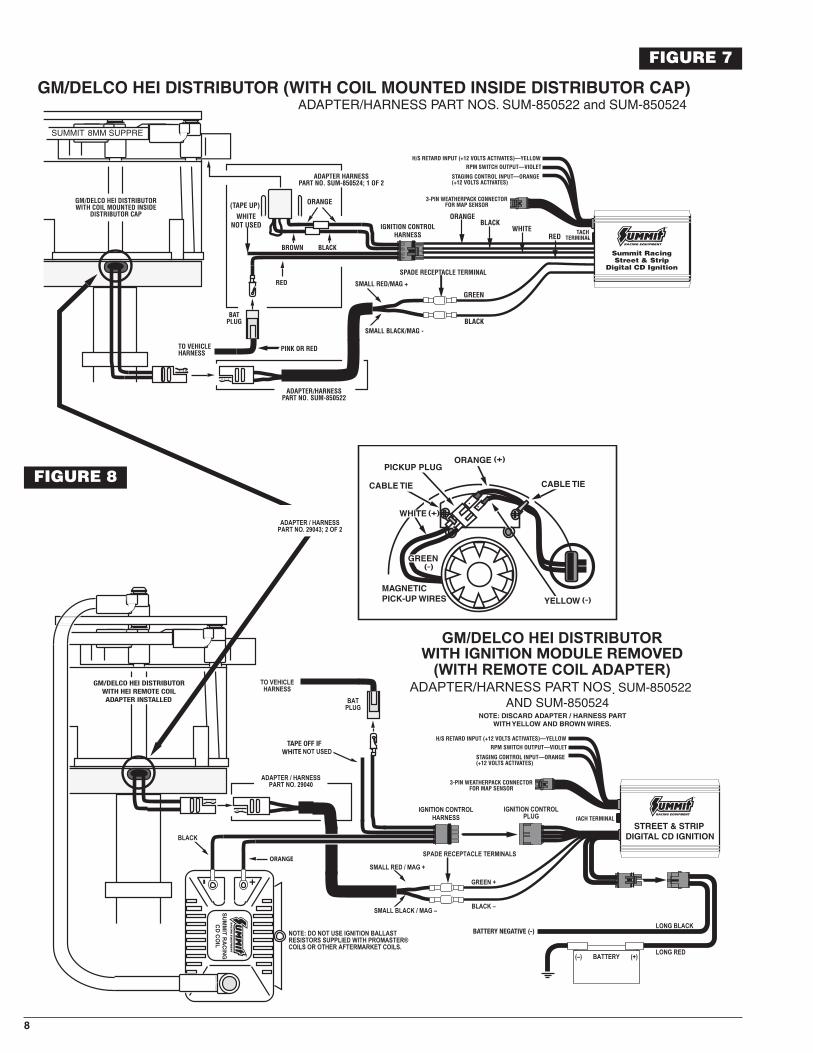
Connecting to Early Model GM HEI Systems (non-computer type) usingAdapter Part No. SUM-850524 and Harness Part No. SUM-850522 for OEMmagnetic pickup. Refer to Figures 7 while performing the following steps.
Connecting the Adapter Part No. SUM-850524:
For coil-in-cap distributors only• Disconnect the (RED or PINK) BAT PLUG/wire from the distributor cap.
• Disconnect the tachometer wire from the TACH terminal on the distributor cap.
• Disconnect the distributor plug from the distributor cap. For coil-in-cap distribu-tors and external coil.
• Remove the distributor cap.
• Disconnect the pickup plug from the ignition module.
• Remove the ignition module, radio noise filter/capacitor and distributor plug harness.
• Slide the adapter ORANGE and YELLOW WIRES through the grommet (supplied).
• Connect the adapter ORANGE WIRE to the pickup plug’s WHITE WIRE.
• Connect the adapter YELLOW WIRE to the pickup plug’s GREEN WIRE.
• Position the grommet into the slot on the edge of the distributor housing. Usecable ties and 8-32 screws to hold wires in place.
• Install the distributor cap.
Connecting the Harness Part No. SUM-850522:• Connect the ignition control’s SMALL GREEN WIRE to the harness RED WIRE.
• Connect the ignition control’s SMALL BLACK WIRE to the harness BLACK WIRE.
• Connect the mating plug of the harness to the mating plug of the adapter PartNo. SUM-850524 from the distributor.
Connecting the Ignition Control Harness:• Route the ignition control harness to the coil so that its wires do not make
contact with extreme heat, sharp objects or moving devices such as fans, beltsand linkages.
• Crimp a spade terminal on the ignition control harness RED WIRE.
For coil-in-cap distributors onlyRefer to Figure 7 while performing the following steps.• Connect the BAT PLUG/wire to the RED WIRE.
• Crimp the ORANGE WIRE to the YELLOW WIRE of the adapter Part No. SUM-850524 3-pin connector.
• Crimp the BLACK WIRE to the BROWN WIRE of the adapter Part No. SUM-850524 3-pin connector.
• Plug the adapter Part No. SUM-850524 3-pin connector into the distributor cap.
• Note: DO NOT connect the WHITE WIRE of the ignition control harness to anything. Tape the end of it to insulate it.
• Go to Step 3, page 9.
For external coil only
Refer to Figure 8 while performing the following steps.
(Replace the words “spade receptacle terminal” with “ring terminal” whenaftermarket coils with post type terminals are used.)• Disconnect the BAT wire from the ignition coil BAT/(+) terminal. Connect the BAT
wire to the small RED WIRE on ignition box.
• Disconnect the tachometer wire from the ignition coil TACH/(–) terminal.
• Crimp a spade receptacle terminal on the ignition control harness ORANGEWIRE. Connect the ORANGE WIRE to the ignition coil BAT/(+) terminal. DO NOTallow any wire except the ORANGE WIRE to make contact with the ignition coilBAT/(+) terminal.
• Crimp a spade receptacle terminal on the ignition control harness BLACK WIRE.Connect the BLACK WIRE to the ignition coil BAT/(–) terminal.
• Note: DO NOT connect the WHITE WIRE of the ignition control harness to anything. Tape the end of it to insulate it.
• Go to Step 3, page 9.
Connecting to Mopar/Chrysler Electronic Systems (non-computer type)using harness Part No. SUM-850522 for OEM magnetic pickup
Refer to Figure 16 while performing the following steps.• Disconnect all connectors at the ignition module, ignition coil and distributor.
Remove the ignition module. Take notice of a DARK GREEN/RED WIRE connected to the ignition ballast resistor. Remove the distributor and coil harnesses.
Connecting the Harness Part No. SUM-850522:• Connect the ignition control’s SMALL GREEN WIRE to the harness RED WIRE.
• Connect the ignition control’s SMALL BLACK WIRE to the harness BLACK WIRE.
• Connect the mating plug of the harness to the distributor plug.
Connecting the Ignition Control Harness:• Route the ignition control harness to the ignition coil so that its wires do not
make contact with extreme heat, sharp objects or moving devices such as fans,belts and linkages.
• Connect the RED WIRE to the terminal on the ignition ballast resistor that previously had the DARK GREEN/RED WIRE connected to it (or to a 12-volt wirefrom the ignition switch). NOTE: The RED WIRE must get voltage when theignition switch is in the START and RUN positions.
• Connect the ORANGE WIRE to the ignition coil (+) terminal. DO NOT allow any wire except the ORANGE WIRE to make contact with the ignition coil (+) terminal.
• Connect the BLACK WIRE to the ignition coil (–) terminal.
• DO NOT connect the WHITE WIRE of the ignition control harness to anything.Tape the end of it to insulate it.
• Go to Step 3, page 9.

AB
CD
SUM-850516
SUM-850516
BATTERY NEGATIVE (-)
OR PINK
WHITE
ORANGE
WHITE
PINK OR
WHITE
DUAL CONNECTOR
AB
CD
SUM-850518
SUM-850518
BATTERY NEGATIVE (-)
FIGURE 3
FIGURE 4
5

6
FIGURE 5
MAG –
MAG +
ORANGE MAG +
PURPLE MAG –
ATTACH TO BAT-
TAPE OFF IF WHITE NOT USED
ORANGE

7
(2b) Wiring method without adapters; all breaker point distributors; Summit Racing MBI Distributor (three wire/red,brown, green); OEM electronic ignition amplifiers.
Refer to: Figure 12 for breaker point distributors; Figure 11 for MalloryUNILITE® Distributors, Magnetic Breakerless Distributors or ElectronicAdvance Distributors (three wire/red, brown, green); Figure 12 for OEMelectronic ignition amplifiers.
Connecting the Ignition Control Harness• Route the ignition control harness to the ignition coil so that its wires do not
make contact with extreme heat, sharp objects or moving devices such as fans,belts and linkages.
• Disconnect ALL wires located on the ignition coil (+) terminal. These include thewires from the ignition switch/ignition ballast resistor, start/ignition bypass andany other wires normally connected to the ignition coil (+) terminal. Connectthese wires to the RED WIRE. NOTE: The RED WIRE must get voltage when theignition switch is in the START and RUN positions. If you are using a SummitRacing MBI Distributor, connect its BROWN WIRE to engine ground and add itsRED WIRE to the Ignition Control Harness RED WIRE. Use Ring TerminalConnectors to join wires together (See page 2 - Ignition Ballast Resistor/LoomResistance Wire and Standard Ignition Bypass).
• Similarly, disconnect ALL wires located on the ignition coil (–) terminal. Connectthese wires to the WHITE WIRE. If you are using a Summit Racing Street & StripDigital CD Ignition, add its WHITE WIRE to the Ignition Control Harness WHITEWIRE. Use Ring Terminal Connectors to join wires together.
• Connect the ORANGE WIRE to the ignition coil (+) terminal. DO NOT allow any wire except the ORANGE WIRE to make contact with the ignition coil (+) terminal.
• Connect the BLACK WIRE to the ignition coil (–) terminal.
• Go to Step 3, page 9.
RING TERMINAL CONNECTORS:Two ring terminal connectors are furnished with the ignition control for the conven-ience of getting a neat installation when the ignition control is added to an existingignition system. These ring terminal connectors allow the existing ignition systemwiring to remain in the area of the ignition coil.
• Move wires onto the stud that is inside the ring terminal connector body.
• Secure these wires to the stud with the nut and washer.
• Install the ring terminal connector cap.
(2c) Wiring Method without adapters for Magnetic Pickup TriggerPulses (Non-Computer Type); Magnetic Pickup Distributors orCrank Trigger Ignition
Connecting to Magnetic Pickup Distributors and Crank Trigger Ignition –Refer to Figure 13. Refer to Figure 6 for proper hookup.• Connect the magnetic pickup (+) wire to the SMALL GREEN WIRE from the
ignition control.
• Connect the magnetic pickup (–) wire to the SMALL BLACK WIRE from the ignition control.
Connecting the Ignition Control Harness:• Route the ignition control harness to the ignition coil so that its wires do not
make contact with extreme heat, sharp objects or moving devices such as fans,belts and linkages.
• Connect the RED WIRE to the 12-volt wire from the ignition switch. NOTE: TheRED WIRE must get voltage when the ignition switch is in the START and RUNpositions. Use a ring terminal connector to join wires together.
• Connect the ORANGE WIRE to the ignition coil (+) terminal. DO NOT allow any wire except the ORANGE WIRE to make contact with the ignition coil (+) terminal.
• Connect the BLACK WIRE to the ignition coil (–) terminal.
• DO NOT connect the WHITE WIRE of the ignition control harness to anything.Tape the end of it to insulate it.
• Go to Step 3, Page 9.
MAGNETIC PICKUP/CRANK TRIGGER COLOR CODESBRAND/TYPE MAG+ MAG–SUMMIT BILLET COMPETITION DISTRIBUTOR ORANGE/BLACK VIOLET/BLACK
SUMMIT HARNESS PART NO. SUM-850522 RED BLACKMALLORY CRANK TRIGGER PURPLE GREENMALLORY BILLET COMPETITION DISTRIBUTOR, SERIES NOS. 81 AND 84 ORANGE PURPLEMALLORY COMP 9000® SERIES NOS 96-99 ORANGE PURPLEMALLORY HARNESS PART NO. 29040 RED BLACKMSD™ CRANK TRIGGER PURPLE GREENMSD™ CRANK TRIGGER (OLD STYLE) ORANGE BLACKMSD™ DISTRIBUTOR ORANGE PURPLEMOROSO™ CRANK TRIGGER BLACK WHITEACCEL® CRANK TRIGGER BLACK WHITECHRYSLER ELECTRONIC DISTRIBUTOR ORANGE BLACKFORD DURASPARK DISTRIBUTOR ORANGE PURPLEDELCO/GM HEI DISTRIBUTOR WHITE GREEN
FIGURE 6
8
SUM-850522 AND SUM-850524
BATTERY NEGATIVE (-)
WITH IGNITION MODULE REMOVED
GM/DELCO HEI DISTRIBUTORWITH HEI REMOTE COILADAPTER INSTALLED
TAPE OFF IF
(-)
(-)
(+)
(+)
GREEN
BLACK
WHITENOT USED
ORANGE
ORANGEBLACK
REDWHITE
(TAPE UP)
FIGURE 7FIGURE 7
FIGURE 8

9
AB
CD
SUM-850518
SUM-850518
BATTERY NEGATIVE (-)
FIGURE 9
FIGURE 10Step 3
Tachometer Operation:If a tachometer is used, connect tachometer ignition sensing lead to the TACH terminal on the ignition control.
If the tachometer does not work after being connected to the TACH terminal, connect the tachometer ignition sensing lead to the WHITE WIRE from the ignition control harness. If this does not work, your tach is a high voltage triggertach and will require the Summit Fuel Injection and Tachometer Adapter Part No. SUM-850511 or SUM-850512 to supply the proper signal for the tachometer tooperate.
Step 4Secure all wires with cable ties to prevent contact extreme heat, sharp objects ormoving devices such as fans, belts and linkages.
Step 5Recheck all wire and connections to ensure they are correct before applying power.
Step 6Connect the battery (–) terminal cable. Start engine and check operation of the ignition system.
TACH/RPM OUTPUT

10
SUMMIT RACING STREET & STRIP READY-TO-RUN BILLET DISTRIBUTOR, MAGNETIC BREAKERLESS DISTRIBUTORS, OR ELECTORNIC ADVANCE DISTRIBUTORS (3-WIRE: RED, BROWN, GREEN)
BATTERY NEGATIVE (-)
FIGURE 11
FIGURE 12
FIGURE 13
STREET & STRIP DIGITAL CD IGNITION
BATTERY NEGATIVE (-)
OEM IGNITION AMPLIFIERBREAKER POINTS DISTRIBUTOR
SEE WIRE COLOR CHARTPAGE 3
STREET & STRIP DIGITAL CD IGNITION
SUMMIT RACING STREET & STRIP MAGNETIC PICK-UP DISTRIBUTOR OR CRANK TRIGGER IGNITION
BATTERY NEGATIVE (-)

FIGURE 14
FIGURE 15
Top Panel Operation and Features
Summit Racing Street & Strip Digital CD Ignition System
The Summit Racing Street & Strip Digital CD ignition system has a number of features that are set up by using the top panel display and switches. Here is a listof the different features (or modes):
Mode 1 – This is the normal engine protection RPM limit. It is active if no otherRPM limit is selected. The range of this limiter is 1,000 to 12,000 in steps of 100RPM.
Mode 2 – This is the auxiliary RPM limiter, and it is activated when 12 volts isapplied to the ORANGE wire coming out of the end panel. The range is the same as the Mode 1 RPM limiter. This RPML will over-ride the Mode 1 RPML when it isactive.
Mode 3 – This is a selectable high-speed timing retard. It is selected when the YELLOW wire coming out of the end panel has 12 volts applied. The range is 1 to15 degrees in .1 degree steps.
Mode 4 – Start retard value. This amount of retard is applied whenever the engineRPM is below 500. The range is .1 to 10 degrees in .1 degree steps.
Modes 5 and 6 – These two control the built-in RPM activated “window” switch.Mode 5 sets the RPM where the switch activates, and mode 6 sets the RPM wherethe switch de-activates. This is useful if, for example, you want to have yournitrous system only work within a certain RPM range. The output wire for the RPMswitch is the VIOLET wire coming out of the end panel. It is connected to groundwhen the switch is active, and has a maximum current rating of 10 amps. NOTE:The RPM range for this switch is 1,000 to 12,000 and the off RPM (mode 6) mustbe at least 100 RPM higher than the on RPM (mode 5).
Mode 7 – Tach test. This feature allows you to check the accuracy of yourtachometer and any accessories connected to the tach output terminal. It also willactivate the built-in RPM switch in the ignition control. To use the tach test feature,turn the ignition switch on without starting the engine. Select mode 7. Turn theignition switch off briefly, then back on again. The ignition controls will be generat-ing a signal at the tach output terminal at the RPM displayed on the top panel. Youcan use the UP and DOWN arrow keys to change the RPM to the desired value.
To return to normal operation, select mode 1. Turn the ignition switch off. The nexttime the ignition switch is turned on, the ignition control will be out of the tach testmode.
Mode 8 – Boost timing retard degrees per PSI of boost. If you have the includedMAP sensor connected, the ignition control will retard the timing as the boost pressure increases. Mode 8 tells the system how many degrees to retard the timingfor each pound of boost. The MAP sensor plugs into the 3 wire connector thatcomes out of the front panel. If you don’t have the MAP sensor installed, this function has no effect.
Mode 9 – Cylinder number select. Set this to however many cylinders your enginehas. The range is 3 to 12, even-fire ONLY!
Mode A – MAP sensor select. This ignition includes a 2 bar MAP sensor (SUM-850527), which is good for about 15 PSI of boost, plus the necessary harness(SUM-850526). Use mode A to tell the ignition control that you are using a 2 barMAP sensor. If you don’t have a MAP sensor installed, this function has no effect.
BYPASS CONNECTOR
The bypass connector (standard ignition bypass) fits into the mating plug of theignition control harness to convert back to standard ignition. If you use the bypassconnector, use ignition ballast resistors designed for the particular distributor andcoil in the wire from the ignition switch. DO NOT put the bypass connector into themating plug of an RPM Limiting Adapter, or Single or Multi-Stage High SpeedRetard. DO NOT put the bypass connector into the mating plug of an ElectronicAdvance Computer or Remote Timing Control. Use the power plug to convert backto standard ignition. Also, if you are using a Summit Fuel Injection/TachometerAdapter (Part No. SUM-850511 or SUM-850512), disconnect it (and its diode ifused) as part of converting back to standard ignition. The bypass connector(standard ignition bypass method to convert back to standard ignition) does notwork with magnetic pickup distributors or crank trigger ignition.
PUSH THESE TORAISE OR LOWERTHE SELECTEDMODE VALUE
THIS WILL BLINKDURING CRANKINGIF THE TRIGGERSIGNAL IS PRESENT
PUSH THIS BUTTON TOSELECT THE MODE
11

12
SUMMIT RACING EQUIPMENT1200 SOUTHEAST AVENUETALLMADGE, OHIO 44278800.230.3030 FORM #1478SUM REV 2/14/08
Summit Racing Street & StripBoost Timing Master Multi-Spark
Digital CD Ignition WarrantySummit Racing Equipment warrants this product for 1 year from date of purchase. If used for racing or competition, this warranty islimited to manufacturer defects only; wear and breakage are not covered under any circumstances.
If the product shows, in our opinion, evidence of being used or installed contrary to the instructions and/or subjected to improper handling, packaging, or shipping by the customer, it will not be covered by our limited warranty.
Summit Racing Equipment’s liability for losses or damages, arising out of any cause whatsoever, is limited to full refund of the purchaseprice or, at our option, repair or replacement of the product(s). Summit Racing Equipment shall not be liable for any consequential orincidental damages. Some states do not allow exclusion or limitation of consequential or incidental damages, so the above limitation or exclusion may not apply to you.
FIGURE 16
BLACK (SMALL 18 GA)
ORANGE
COIL
WHITENOT USED
YELLOWTO TACHOMETER
RED (LARGE 14 GA)TO BATTERY POS (+)
BLACK (LARGE 14 GA)TO BATTERY NEG (-)
RED (SMALL 18 GA)FROM ORIGINAL COIL (+) TERMINAL
BLACK
ORANGE
UNPLUGCHRYSLER MODULE
GREEN
GREEN
PURPLE6 FT EXTENSION CABLECUT ONE END ANDSPLICE AS SHOWN
SPLICE
SUMMIT RACINGSTREET & STRIPDIGITAL CD IGNITION
PURPLE