Embed Size (px)
Citation preview
Lego Mindstorms Robotic Football
i
Summary
This report documents the development and evaluation of a robotic footballer. Similar projects have
been undertaken in the past, but various topics were left open for further investigation. The robot was
constructed from a Lego Mindstorms kit, and was programmed in NQC to allow rapid development.
Both mechanic and software issues had to be considered, such as the type of mechanisms required, the
software methodology to be used and so on.
The minimum requirements were:
• To design and produce a robot from a single Mindstorms kit, capable of autonomous
navigation around a pitch of given dimensions.
• To enhance the robot so that it is able to perform three footballing tasks, such as locating the
ball, making for the ball, dribbling with the ball, kicking the ball, and so on.
• To incorporate two RCX microcomputers on a single robot, and consider communication
between the two.
• To investigate what benefits, if any, result from incorporating two RCXs on a single robot.
The possible extensions were:
• To investigate the RCX communication mechanism itself.
• To test the reliability of the RCX communication mechanism under different conditions.
• To enhance the robot so that it is capable of automatic calibration before a match to adjust for
different pitch surfaces, lighting conditions, and pitch size.
• To experiment with how different kinds of pitch markings could be used to aid self-location
techniques.
• To enhance the robot so that is able detect whether its dead-reckoning system has failed, and
automatically re-calibrate itself.
• To enhance the robot so that it capable of employing a range of tactics, for example defensive
or offensive approaches to the game.
• To experiment with the possibility of communication between two or more robots.
• To experiment with the possibility of communication between a robot and a personal
computer.
Lego Mindstorms Robotic Football
ii
Acknowledgements
I would like to thank:
Tony Cohn for his help throughout the project, especially at the invaluable weekly meetings.
Andy Bulpitt for his feedback on my midterm report.
My mum and dad for showing enthusiasm towards the project, feeding me, and getting me out of bed
during the Easter holiday.
Karlie for aiding my mum and dad when attempting to get me out of bed, and for being there when I
needed her.
Lego Mindstorms Robotic Football
iii
Table of Contents
1 Introduction 1 1.1 Aim 1 1.2 Objectives 1 1.3 Relevance of Project to the Computing Degree 1 1.4 Structure of this report 1
2 Background to the problem 2 2.1 The Literature Review 2 2.2 Sources of Information 2 2.3 Lego Mindstorms and the RCX 3
2.3.1 Introduction to Lego Mindstorms 3 2.3.2 RCX Sensor Ports 3 2.3.3 RCX Output Ports 4 2.3.4 RCX Communication 5 2.3.5 Additional RCX Features 5
2.4 RoboCup 6 2.4.1 The History of RoboCup 6 2.4.2 RoboCup Junior Rules 6
2.5 Robotics and Mechanics 6 2.5.1 Robot Locomotion 6 2.5.2 Wheel Arrangements 7 2.5.3 Robot Kinematics 8 2.5.4 Self-Localisation 8 2.5.5 Collision Detection 9 2.5.6 Ball Finding 9 2.5.7 Ball Control 10 2.5.8 Actuators 10 2.5.9 Sensors 10
2.6 RCX Programming 11 2.6.1 GUI-Based Languages 11 2.6.2 NQC 11 2.6.3 Other Languages 12 2.6.4 Firmware Replacements 12
2.7 Software Architecture 12 2.7.1 Intelligent Agents 12 2.7.2 Traditional Approach Vs Behaviour Control 13
2.8 Similar Projects 13 2.8.1 Summary 13 2.8.2 Limitations and Possible Improvements 14 2.8.3 Areas of Interest 15
2.9 Project Methodology 15 2.10 Project Schedule 16
3 Initial Design 17 3.1 Locomotion and Turning 17 3.2 Ball Finding 18 3.3 Self-Localisation 19 3.4 Using the Grey-Scale Pitch 20 3.5 Collision Detection 21 3.6 Ball Control 22 3.7 Goal Scoring 24
Lego Mindstorms Robotic Football
iv
3.8 Overall Lego Mindstorms Architecture 24 3.9 RCX Communication 27
3.9.1 Timing Issues 27 3.9.2 Reliability Issues 28 3.9.3 Protocol Issues 28
4 Implementation of Design 29 4.1 Methodology 29 4.2 Locomotion and Turning 30 4.3 Self –Localisation 30 4.4 Ball Finding 33 4.5 RCX Communication 36 4.6 Using the Grey-Scale Pitch 36 4.7 Collision Detection 37 4.8 Ball Control 37 4.9 Goal Scoring 37 4.10 Summary of Final Design 38
5 Final Testing 38 5.1 Test Plan 39
5.1.1 Ball Finding 39 5.1.2 Self-Localisation 40 5.1.3 Kicking Mechanism 40
6 Evaluation 40 6.1 Evaluation Methodology 40 6.2 Modularity 41
6.2.1 Modularity of the Physical Design 41 6.2.2 Modularity of Software 41
6.3 Niche Targetability 42 6.3.1 Minimum Requirements Met 42 6.3.2 Extended Requirements Met 45
6.4 Portability 46 6.4.1 Portability of the Physical Design 46
6.5 Robustness 46 6.5.1 Robustness of the Physical Design 46 6.5.2 Robustness of the Software 46
7 Conclusion and Possible Further Work 47 7.1 Conclusion 47
7.1.1 Fulfilment of Project Requirements 47 7.1.2 The Dual Differential Drive as a Locomotion Mechanism 47 7.1.3 NQC as a Development Language 47
7.2 Further Work 48 7.2.1 Calibration 48 7.2.2 Goal Scoring 48 7.2.3 Alternative Tactics 48 7.2.4 Teamwork and Message Passing Between robots 48 7.2.5 Alternative Projects 50 7.2.6 Message Passing Between Robots and a PC 50 7.2.7 Genetic Algorithms 50 7.2.8 Alternative Programming Languages 50
References 51
Lego Mindstorms Robotic Football
v
Appendix A – Personal Reflection 53 7.3 Aspects of the project that went particularly well 53 7.4 Aspects of the project that did not go particularly well 53 7.5 Advice to Students Considering Undertaking a Similar Project 53 7.6 Advice for Future Students Undertaking Similar Projects 53 7.7 Advice for Future Students in General 54 7.8 Evaluation of Project Schedule 55
Appendix B – Project Schedule 56
Appendix C - Test Results 56 Dead Reckoning Experiments 57 RCX Communication Experiments 57 Final Testing 58
Appendix D – NQC Code 60 Code for Master RCX 60
Global Definitions 60 Inverse Cosine Function 60 Trigonometry Function 61 Kick Function 63 Rotate Function 64 Ball Finding Task 65 Goal Scoring Task 66 Initialisation Function 66 Backup Function 66 Main Task 67
Code for Slave RCX 68 Calibration Function 68 Main Task 69
Appendix E – Photographs 72
Appendix E – Photographs 72
Appendix F - Glossary 73
Lego Mindstorms Robotic Football
1
1 Introduction
1.1 Aim The aim of this project was to produce an autonomous robotic footballer from one or more Lego
Mindstorms kits, with the hope of investigating the effects of introducing a second RCX
microcomputer.
1.2 Objectives The objectives of the project were to:
• Research into similar projects, identifying problems encountered, and possible improvements.
• Produce a robotic footballer, taking into account the findings of the research phase, and
lessons learned during development.
• Discover the drawbacks and benefits of incorporating two RCX microcomputers on a single
robot, and the drawbacks and benefits of different physical mechanisms with respect to
mobile robotics.
The minimum requirements are stated in the Summary.
1.3 Relevance of Project to the Computing Degree There were two distinct aspects to this project. Firstly, a robot had to be constructed, and secondly it
had to be programmed to behave appropriately. It is not difficult to see the relevance of the latter of
these issues to a computing degree, as a large proportion of the course is related to programming.
Taking five artificial intelligence modules proved to be useful, as many of the various topics taught in
the associated lectures were applied to the robot being produced. The physical construction phase was
less relevant to the degree programme, but again, the design had to be based around AI paradigms.
1.4 Structure of this report Throughout this report, the robot being produced is referred to as SoccerBot. The contents of the
various chapters are as follows.
Chapter 1: This chapter sets out the objectives of the project, but does not provide any
background information regarding technologies and paradigms that might be used on SoccerBot, nor
suggest how any of the targets might be achieved.
Chapter 2: Chapter two documents findings of a literature review of relevant materials, which
were later drawn upon in the design and implementation stages. The review covers Lego Mindstorms,
RoboCup, various aspects of robotics, and finally programming issues.
Lego Mindstorms Robotic Football
2
Chapter 3: Chapter 3 describes how it was intended that SoccerBot would be constructed and
programmed.
Chapter 4: Chapter 4 describes the implementation process itself in a step-by-step fashion,
pointing out any problems encountered, how they were solved, and how the initial design had to be
adapted.
Chapters 5, 6 and 7: The final chapters (5, 6 and 7) describe the testing procedure, the
evaluation criteria used along with the results of applying the criteria, and any conclusions drawn.
2 Background to the problem
2.1 The Literature Review An extensive literature review was carried out before proceeding with the development of the robot.
In conducting the review, the following questions were considered in turn:
• What is Lego Mindstorms?
• How are robots created with Lego Mindstorms?
• What are the limitations of Lego Mindstorms?
• What is RoboCup?
• What are the rules of RoboCup Junior?
• What kind of mechanisms will the robot need?
• How might the robot be programmed?
• What has been done in similar projects in the past?
2.2 Sources of Information A search on the universities library information system for “Lego Mindstorms” returned a book by
Baum et al (2001), which proved to be an invaluable source of information along with Baum (2002),
which was provided by my supervisor. The foremost includes an in depth discussion of the internals
of the RCX, and the other provides step-by-step instructions on how to build a diverse range of robots,
from a simple line-following robot to a vending machine. For general robotic paradigms and theories,
Jones, Seiger and Flynn (1998) also helped, although most of the principals introduced were beyond
the scope of the project, and slightly out of date in some cases.
Searches for “robot” and “robotics” returned a wide variety of sources, the most interesting of
which were the reports on a maze-solving robot by Kevan, Paul (2003), and a robotic sheep dog, by
Sumpter, Neil (2000), but neither of these were considered particularly relevant, and hence were not
analysed in detail.
After browsing through the previous student’s project titles, the reports for four projects,
Goddard (2002), Fordham (2003), Varsani (2003) and Burbidge (2003), were deemed to be the most
Lego Mindstorms Robotic Football
3
relevant. Each of these student’s projects involved designing and building a robotic footballer from
Mindstorms kits.
2.3 Lego Mindstorms and the RCX
2.3.1 Introduction to Lego Mindstorms SoccerBot was to be constructed from one or more Lego Mindstorms Robotics Invention Systems.
“Mindstorms sets add a new dimension to the Lego universe. Lego models can be more than just a collection of beams, bricks, gears, and motors. They can sense and respond to their environment, and can be programmed to accomplish nearly anything, from picking up and stacking bricks, to playing ‘tag’ with one another” (Baum et al, 2001).
Mindstorms robots are controlled by RCX microcomputers (or Robotic Command eXplorers).
Each RCX has a number of sensor ports and output ports, which can be connected to sensors or
motors via wires. In typical Lego fashion, the connectors on each end of the wires simply click into
place (Baum, 2002). This gives Mindstorms obvious advantages over typical approaches to building
robots involving “ soldering, metalworking, and other skills, along with a healthy dose of
programming” (Baum, 2002). Included in each kit are two motors, a light sensor, two touch sensors,
an RCX, an infrared tower, and a useful selection of Lego pieces.
The RCX has only three sensor ports and three output ports, but it is sometimes possible to
overload a port with more than one sensor (Baum, 2002). Programs are downloaded to an RCX from a
PC via the infrared tower. The sensor ports can be used as inputs to a program, and the output ports
can be used to control motors. It was obvious that SoccerBot, like all Mindstorms robots, would need
to monitor changes in the environment via sensors connected to the sensor ports, and take action by
activating motors connected to the output ports.
The previous students Goddard (2002), Fordham (2003), Varsani (2003), and Burbidge (2003)
were each limited to a single RCX to control their robot. This restriction did not apply to this project,
which presented the opportunity for an investigation into the benefits of incorporating two RCXs on a
single robot.
2.3.2 RCX Sensor Ports There are two classes of sensors – active and passive. Active sensors (sometimes called powered
sensors) require power to operate, whereas passive sensors do not. The programmer must specify
what kinds of sensors are attached to the RCX and how to read them (Baum et al, 2001). The standard
Mindstorms sensors available are touch sensors, light sensors, rotation sensors and temperature
sensors, and each has an associated sensor type that must be set within the program running on the
RCX (Baum, 2002).
Baum et al (2001) cleverly explained how it can sometimes be useful to intentionally fool the
RCX. For example, the light sensor (normally used as an active sensor for detecting light reflected
Lego Mindstorms Robotic Football
4
back from its associated LED) can apparently be used to detect ambient light levels. This is achieved
by configuring the program to use a light sensor as a passive sensor, thus disabling the LED.
As well as considering the sensor type, various sensor modes are available, which tell the RCX
how to interpret the sensor’s values. Languages such as RCX code set the sensor mode automatically,
whereas others (such as NQC) allow sensor modes to be set by the programmer (Baum et al, 2001).
Sensor types and sensor modes are detailed in the Appendix.
The standard firmware samples sensor readings every three milliseconds (ms) and for each
sensor, three values are stored; the raw value, a Boolean value and a processed value. The raw value
maps the actual voltage to a range of 0 to 1023, and the Boolean value maps voltages to either 0 or 1,
whereas the processed value is dependant on the sensor mode.
Boolean values are most commonly used with touch sensors, but they are occasionally useful
when reading other types of sensors too. High raw values result in a Boolean value of 0, and low raw
values result in a Boolean value of 1. To reduce the amount of jitter in a Boolean conversion between
successive readings, a method called hysteresis is used (Baum et al, 2001).
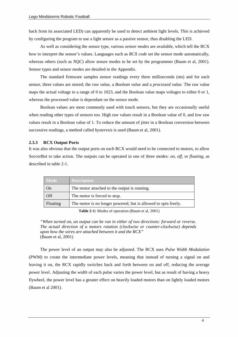
2.3.3 RCX Output Ports It was also obvious that the output ports on each RCX would need to be connected to motors, to allow
SoccerBot to take action. The outputs can be operated in one of three modes: on, off, or floating, as
described in table 2-1.
Mode Description
On The motor attached to the output is running.
Off The motor is forced to stop.
Floating The motor is no longer powered, but is allowed to spin freely.
Table 2-1: Modes of operation (Baum et al, 2001)
“When turned on, an output can be run in either of two directions: forward or reverse. The actual direction of a motors rotation (clockwise or counter-clockwise) depends upon how the wires are attached between it and the RCX” (Baum et al, 2001)
The power level of an output may also be adjusted. The RCX uses Pulse Width Modulation
(PWM) to create the intermediate power levels, meaning that instead of turning a signal on and
leaving it on, the RCX rapidly switches back and forth between on and off, reducing the average
power level. Adjusting the width of each pulse varies the power level, but as result of having a heavy
flywheel, the power level has a greater effect on heavily loaded motors than on lightly loaded motors
(Baum et al 2001).
Lego Mindstorms Robotic Football
5
2.3.4 RCX Communication It was thought likely that for two RCXs to work well together, they would need to be able to talk to
each other. Fortunately, a mechanism for communication between one RCX and another is provided
in the standard firmware, allowing messages with values between 1 and 225 to be passed in either
direction (Baum et al, 2001). Sending more complex messages is challenging
(http://www.contrib.andrew.cmu.edu/~rgockley/legos/ir.html [29th February 2004]). The most recent
message received is stored in a buffer, which can be queried at any time. A value of zero means that
no message has been received (Baum et al, 2001).
Infrared communication is relatively cheap and simple, but has various problems. For example,
infrared emissions from the sun can flood receivers, rendering them unable to see any incoming
messages. There are also issues with line-of-sight. For two RCX’s to talk to each other, they need to
be pointed roughly towards each other (http://www.contrib.andrew.cmu.edu/~rgockley/legos/ir.html
[29th February 2004]).
Messages are sent in packets, consisting of a header, and the payload. The header tells the RCX
where the packet starts, and the payload is the data itself. The payload of a message sent from one
RCX to another is two bytes long, the first of which simply indicates that the second byte is a
message, and the second of which is the message itself
(http://www.contrib.andrew.cmu.edu/~rgockley/legos/ir.html [29th February 2004]). As explained in
section 2.7, none of the previous students at the University of Leeds (Goddard, 2002), (Fordham,
2003), (Varsani, 2003), and (Burbidge, 2003) have experimented with RCX communication, leaving
the topic open for investigation. The communication mechanism is discussed in more detail in section
3.8.
2.3.5 Additional RCX Features The RCX has various features in addition to those mentioned so far. These are discussed in detail by
Baum et al (2001), but the important points (taken from the book) are listed below.
The Datalog: The datalog allows a program to store a sequence of values (such as sensor
readings), which can later be uploaded to a PC for analysis. The RCX’s display indicates how much
of the datalog is currently filled up.
LCD Display: “ The LCD can display a four-digit signed number and a single-digit unsigned
number, as well as various special indicators” (Baum et al, 2001). The display can be used for
debugging purposes.
Sound: Six predefined sounds can be played, and custom sounds are also possible. Emitting
sounds can be useful for signalling that a certain event has occurred, and could in theory be used as a
primitive form of communication between two RCX’s (although unlikely to work well in practice).
Lego Mindstorms Robotic Football
6
Timers: The standard firmware provides four timers that measure time in increments of 100ms.
Each timer can be reset independently at any time, and will reset automatically after about 55 minutes.
The RCX also has a system clock (called the watch), which stores the number of minutes that have
passed since the RCX was switched on.
2.4 RoboCup
2.4.1 The History of RoboCup Initially an idea of Professor Alan Mackworth, “ The Robot World Cup Initiative (RoboCup) is an
attempt to foster AI and intelligent robotics research by providing a standard problem where a wide
range of technologies can be integrated and examined”
(http://www.csl.sony.co.jp/person/kitano/RoboCup/RoboCup-old.html [20th November 2003]).
There are various different leagues in the Robotic World cup, including a Legged Robot
League, and an Expert Robot League. These Leagues are, however, beyond the scope of this project,
which will instead be concerned with RoboCup Junior.
2.4.2 RoboCup Junior Rules The idea of RoboCup Junior is to allow (relatively) primitive robots to compete in a game similar to
real football. Obviously, the pitch is somewhat smaller, and various rules are omitted. The rules can
be found at (http://demo.cs.brandeis.edu/rcj2001/soccer.html. [November 2003]), and are summarised
below.
The pitch: The playing field is 87cm by 119cm. The walls are 5.5 inches (14 cm) high and are
matt black, whereas the goals are painted grey. Perhaps the most important thing to note is that the
floor of the pitch is painted in grey-scale; in particular, one end of the pitch is black, and the other end
is white, with a constant gradient in-between.
Competing Robots: There are rules governing the dimensions and decoration of robots, but
these rules will be overlooked if they appear to be hindering progress.
The Ball: The ball used in Robocop Junior about four inches in diameter, and emits infrared
light, which allows competing robots to locate it.
Other Rules: As common sense would suggest, foul play is not allowed, and goals are
followed by kick-offs, however there are no throw-ins, or free kicks etc.
2.5 Robotics and Mechanics
2.5.1 Robot Locomotion In order to be able to compete in a game of football, SoccerBot must have some means of
travelling from one place to another on the pitch. Various mechanical mechanisms can be used for this
purpose, and the choice of mechanism has implications on a robots performance.
Lego Mindstorms Robotic Football
7
From research, it is apparent that “ Wheeled vehicles are by far the most popular for several
practical reasons” (Jones, Sieger, Flynn, 1998). Alternatives include tracked vehicles, and legged
vehicles. Each kind has associated advantages and disadvantages with respect to their efficiency,
reliability, limitations and mechanical complexity. In their book about mobile robots, Jones, Seiger
and Flynn (1998) fail to mention any other alternatives to the three listed above, presumably
dismissing them as impractical for the majority of cases. Furthermore, Baum (2002) in his book about
Lego Mindstorms demonstrates wheeled and tracked robots, but refrains from demonstrating legged
robots, possibly considering them beyond the scope of the book. It would therefore seem sensible to
focus attention on wheeled and tracked vehicles, briefly consider legged vehicles, and discard other
alternatives.
The advantage of wheeled robots is that they are simple to construct, and very reliable in most
cases. One of their main problems is that they have difficulties negotiating uneven terrain. “ As a rule,
a wheeled vehicle has trouble if the height of the object it must surmount approaches the radius of the
wheels” Jones, Seiger and Flynn (1998).
Tracks (such as the ones that can be found on tanks) perform somewhat better on uneven
terrain, and are less susceptible to loose soil, rocks, and other hazards. Tracks however, are relatively
inefficient compared to wheels. Power is dissipated through friction within the tracks, and whilst the
treads slip along the ground when turning (Jones, Seiger and Flynn, 1998).
Legged robots are even more adept at moving around in natural environments, but have various
challenges.
“Many of these challenges stems from the large numbers of degrees of freedom required by legged systems. Since each leg must have at least two-motors, the cost of building the robot is higher relative to those with wheels or tracks; the walking mechanism is also much more complex and is more prone to failure” (Jones, Seiger and Flynn, 1998).
2.5.2 Wheel Arrangements When selecting a wheel arrangement it is important to consider the complexity of the associated
mechanisms, the accuracy of self-localisation techniques made possible, and the associated kinematics
(Jones, Seiger and Flynn, 1998). Kinematics is discussed in the next section, which is followed by a
review of self-localisation techniques.
The differential drive is perhaps the simplest system. It involves two motors, two drive wheels,
and a caster wheel. One motor controls the left drive wheel, another controls the right wheel, and the
caster wheel aids balance. To travel forwards or backwards, both wheels are rotated in the same
direction, whereas to turn, the wheels are rotated at different speeds, or in opposing directions.
Rotating the two wheels at equal an opposite speeds allows rotation on the spot (Jones, Seiger and
Flynn, 1998, pp. 172 - 174). The main problem with the approach is that the two motors may not
rotate at exactly the same rate when attempting to travel in a straight line, causing the vehicle to drift
from the straight path, adversely affecting self-localisation accuracy (Baum 2002).
Lego Mindstorms Robotic Football
8
The problems of the basic differential are overcome by a more complex mechanism called the
dual differential drive. The key components required are the same in both drives, but the underlying
drive train is much more complex. Gears are arranged in such a way that one motor can perform
straight-line movement, and another is responsible for rotation on the spot, so that drift is no longer a
problem (Baum 2002).
The synchro drive is another mechanically complex locomotion technique allowing accurate
dead reckoning. It involves one motor controlling forward – backward movement, and a second
controlling the orientation of the wheels by pivoting them about the vertical axis (Jones, Seiger and
Flynn, 1998). Hardware limitations of Lego unfortunately render this option unfeasible.
Ackerman steering, as used in motorcars, is the last arrangement mentioned in the mobile
robotics book (Jones, Seiger and Flynn, 1998). With its four points of suspension, it is very stable, and
allows accurate straight-line movement. The problem with this alternative lies with its kinematics; in
particular, it does not allow on-the-spot rotation, resulting in complex path-planning calculations, as
explained in the next section.
2.5.3 Robot Kinematics Most robots (including SoccerBot) have three degrees of freedom when moving on a flat surface. In
particular, a robot can be at any position specified by a two-dimensional coordinate system (x and y),
and at any orientation (θ). Given these three values as a destination, a robot should be able to move to
the appropriate location, regardless of the starting position. The problem with robots using Ackerman
steering is that their position and orientation are coupled: The robot must move forward in order to
turn. The result is that moving directly from one point to another is not possible, even if there are no
obstructions. The path to be taken may be complex, especially when there are obstacles, which is why
parallel parking is difficult. Robots based on a differential or synchro drive are able to turn on the
spot, decoupling position and orientation (Jones, Seiger and Flynn, 1998).
2.5.4 Self-Localisation Self-localisation is the term given to knowing ones whereabouts in relation to the environment. A
video camera is often used for this purpose, either mounted onto a robot, or mounted above the scene
to allow geometric data to be forwarded to the robot via a communication mechanism. Mindstorms
unfortunately does not include a video camera, and so mounting one onto SoccerBot is unfeasible.
The problem with having data sent from a base station to SoccerBot is that a protocol would have to
be devised for the communication, which would prove difficult considering the limitations of Lego
Mindstorms. Furthermore, it would not be permitted in an official game of RoboCup Junior
http://www.csl.sony.co.jp/person/kitano/RoboCup/RoboCup-old.html [20th November 2003].
The previous students Goddard (2002), Fordham (2003), Varsani (2003), and Burbidge (2003)
all used a form of dead reckoning as a self–localisation technique. For dead reckoning to be made
possible, a robot’ s starting position and orientation must be known, relative to other objects. Using
Lego Mindstorms Robotic Football
9
trigonometry, the three parameters described in section 2.5.4 (x, y, and θ) are updated frequently.
Angles and distances to other objects can then be calculated using the inverse trigonometric functions,
and the Pythagoras theorem respectively. The problem with this approach is that it is prone to
accuracy errors, as all of the previous students Goddard (2002), Fordham (2003), Varsani (2003), and
Burbidge (2003) concluded. Fortunately, it was decided that despite the inaccuracy, results were
acceptable, and recommended for use in future projects such as this.
2.5.5 Collision Detection SoccerBot will inevitably bump into other robots and the walls of the pitch from time to time. Baum
(2002) suggests two types of bumpers that can be mounted on robots to detect collisions in
conjunction with touch sensors. Both his simple approach, and his better bumper are unsuitable, as
there is no gap in the middle in which the ball can be controlled. In previous projects, adapted
versions of the second option did however prove to be effective. The approach used by Varsani (2003)
was to use a light sensor as a proximity sensor, but this only worked when his robot was not in
possession of the ball.
2.5.6 Ball Finding As discussed in the previous section, use of a video camera was ruled out, and so could not be used
for ball finding purposes. It would seem sensible to instead make use of the fact that the special
RoboCup ball emits infrared light in all directions, which can be detected by light sensors. One would
imagine that mounting a ring of light sensors all round the robot would prove to be effective, however
hardware limitations do not permit this, and so a cleverer technique needs to be used.
An idea utilised by many similar projects involves mounting a single light sensor on the front of
the robot. To scan for the ball, the robot spins on the spot until a the light sensor reading reaches a
certain threshold level, and assumes the ball can be found by travelling in that direction. The
advantage of this technique is that it is simple and requires only a single light sensor. A major
complication however is deciding on a suitable threshold value. If set too low, false alarms may
occur, and if set too high, the ball may be missed completely. The problem is that the lighting
conditions, and even the distance between robot and ball affect the ideal threshold value. Having to
stop in order to scan for the ball is also inconvenient, and deciding on how often to re-scan is far from
obvious.
Baum (2002) described a robot that has a head that turns from side to side as it looks for bright
lights, allowing it to proceed on its current course while simultaneously looking for a better
alternative. The basic operation of the so called Scanbot is as follows: “ drive forward while looking
back and forth until a bright light is spotted, then turn a little in the direction of the light, and resume
looking back and forth” (Baum, 2002). If a full 360-degree sweep of the environment is performed,
then the highest light-level reading during the sweep is likely to be in the direction of the ball. This
de-coupling of locomotion direction and viewing direction has various advantages. Firstly, it means
Lego Mindstorms Robotic Football
10
that the robot does not have to stop in order to update its estimation of the ball location, and secondly,
the need for a threshold value is removed. The technique is however more mechanically complex, and
requires an extra rotation sensor in order to record angles.
2.5.7 Ball Control The issue of controlling the ball once in possession is a rather interesting one. None of the previous
University of Leeds students undertaking similar projects have claimed to find a definitive solution to
the problem; there is no silver bullet.
The simplest way to control the ball is to grab it with control arms the moment contact with the
ball is made, so that the ball cannot escape. The reason many similar projects resorted to this
technique, is that without using control arms, the ball tends to bounce off and roll away after the
initial contact, but unfortunately the technique is illegal in RoboCup Junior
(http://demo.cs.brandeis.edu/rcj2001/soccer.html. [November 2003]).
Once the ball has been dribbled into an appropriate position, SoccerBot needs to be able to
shoot the ball into the goal. Ideally, the kicking mechanism would enable kicking in any direction,
along the ground or into the air, with varying degrees of power. Considering the limitations of Lego,
only the latter of these seemed practical, as this is simply a case of varying the power provided to the
motor operating the mechanism. Previous projects have kicked the ball by simply bumping into at
maximum speed, but it is hoped that SoccerBot would use a more elegant technique
2.5.8 Actuators Motors are the only physical actuators available in the Mindstorms kit, and it is unclear as to why any
other kind of actuator would be required. Solenoids may prove useful, however motors can be used to
simulate solenoids when used in conjunction with other Lego pieces. The RCX is also capable of
sounding beeps, and emitting light, which may be useful for diagnostic purposes.
2.5.9 Sensors Using only the four standard Mindstorms sensors available, the possible applications of the kit are
limited. There are however other compatible types commercially available, such as the “ Dual IR
Proximity Detector” , the “ Air Pressure Sensor” , and even a “ Musical Pitch Sensor”
(http://www.techno-stuff.com/sensors.htm [2nd April 2004]). These, like the standard sensors, snap
onto other Lego bricks.
Baum et al (2001) explains how homebrew sensors can also be used in conjunction with the
RCX. In theory it is possible to attach virtually any custom sensor, but obviously there are
complications, including the attachment of the sensor to the robot. Again, it appears that the
Mindstorms kit will be sufficient.
Lego Mindstorms Robotic Football
11
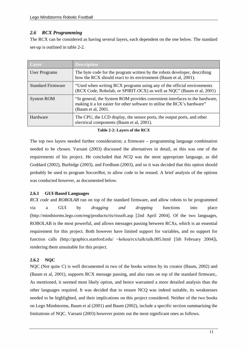
2.6 RCX Programming The RCX can be considered as having several layers, each dependent on the one below. The standard
set-up is outlined in table 2-2.
Layer Description
User Programs The byte code for the program written by the robots developer, describing how the RCX should react to its environment (Baum et al, 2001).
Standard Firmware “ Used when writing RCX programs using any of the official environments (RCX Code, Robolab, or SPIRIT.OCX) as well as NQC” (Baum et al, 2001)
System ROM “ In general, the System ROM provides convenient interfaces to the hardware, making it a lot easier for other software to utilise the RCX’ s hardware” (Baum et al, 2001.
Hardware The CPU, the LCD display, the sensor ports, the output ports, and other electrical components (Baum et al, 2001).
Table 2-2: Layers of the RCX The top two layers needed further consideration; a firmware – programming language combination
needed to be chosen. Varsani (2003) discussed the alternatives in detail, as this was one of the
requirements of his project. He concluded that NCQ was the most appropriate language, as did
Goddard (2002), Burbidge (2003), and Fordham (2003), and so it was decided that this option should
probably be used to program SoccerBot, to allow code to be reused. A brief analysis of the options
was conducted however, as documented below.
2.6.1 GUI-Based Languages RCX code and ROBOLAB run on top of the standard firmware, and allow robots to be programmed
via a GUI by dragging and dropping functions into place
(http://mindstorms.lego.com/eng/products/ris/rissoft.asp [2nd April 2004]. Of the two languages,
ROBOLAB is the most powerful, and allows messages passing between RCXs, which is an essential
requirement for this project. Both however have limited support for variables, and no support for
function calls (http://graphics.stanford.edu/ ~kekoa/rcx/talk/talk.005.html [5th February 2004]),
rendering them unsuitable for this project.
2.6.2 NQC NQC (Not quite C) is well documented in two of the books written by its creator (Baum, 2002) and
(Baum et al, 2001), supports RCX message passing, and also runs on top of the standard firmware,.
As mentioned, it seemed most likely option, and hence warranted a more detailed analysis than the
other languages required. It was decided that to ensure NCQ was indeed suitable, its weaknesses
needed to be highlighted, and their implications on this project considered. Neither of the two books
on Lego Mindstorms, Baum et al (2001) and Baum (2002), include a specific section summarising the
limitations of NQC. Varsani (2003) however points out the most significant ones as follows.
Lego Mindstorms Robotic Football
12
1. Only thirty-two global variables are allowed.
2. Only single 16-bit integer variables are allowed.
3. Only 6KB of user memory is available.
4. There is no real support for process synchronisation
5. A maximum of eight subroutines are allowed per program.
6. Nested subroutines are not supported.
7. Subroutine parameters are not supported.
For traditional software engineering on desktop computers, the first three restraints would be
unsatisfactory, however Baum (2002), having designed NQC, argues that programs written for the
RCX tend to be just hundreds of bytes long, meaning that that the limitations should not present many
problems. One can imagine situations where this might not be the case (for example if a complex
genetic algorithm were to be implemented) but this is not the case with this project.
The forth limitation should again not present a problem as SoccerBot’ s behaviour will not be
critical in that any slight errors resulting from variations in timing and so on will not be disastrous.
The biggest complication regarding synchronisation might stem from NCQ not having support for
critical sections, but again, perfect performance is neither vital, nor feasible. The last three restrictions
will simply mean that care will have to be taken in structuring the code.
2.6.3 Other Languages Golog and LegoLog are Prolog-based languages used commonly in the field of cognitive science, and
are (like NQC) implemented on top of the standard firmware (http://www.cs.toronto.edu/cogrobo/ [5th
February 2004). The main disadvantage of these languages is that documentation is poor, rendering
them an unsuitable choice (Varsani).
2.6.4 Firmware Replacements By using a replacement firmware, limitations of the standard firmware can be overcome. Examples
are brickOS, leJos and pbForth (Varsani). The option of using one of these was tempting, due to the
extra power they provide, but dismissed, as it was anticipated that using them might have introduced
unnecessary complications.
2.7 Software Architecture
2.7.1 Intelligent Agents In artificial intelligence terms, SoccerBot can be considered as an agent. An agent is any entity that
perceives its environment, and acts accordingly (Russell and Norvig, 2003, ch1, pp. 4). SoccerBot
will use Mindstorms sensors to perceive it’ s environment, and motors to take appropriate action.
There are four basic types of agent, namely simplex reflex, model-based, goal-based and utility-based
Lego Mindstorms Robotic Football
13
agents. A decision will have to be made as to which of the above types is most relevant with respect to
SoccerBot, based on the type of environment SoccerBot is likely to find itself in.
An agent’ s environment can be categorised in various ways. SoccerBot’ s can be described as
partially observable, deterministic, dynamic, continuous, and multi-agent. A simplex reflex agent may
not suffice because the environment is dynamic, and only partially observable. Partial observability
can be handled by keeping track of the world the agent can no-longer see, as is the case with model-
based agents (Russell and Norvig, 2003, ch13). The agent also requires some sort of goal information,
as the agent’ s priorities need to change according the situation of the game at any time. Hence it
seems appropriate to implement SoccerBot as a goal based agent.
2.7.2 Traditional Approach Vs Behaviour Control The traditional approach to robotic programming involves decomposing a program into a sequence of
functional components: sensor interpretation, world modelling, planning, and execution. Conflicts and
noise must be resolved so that a consistent model of the world can be constructed, containing the
geometric details of all the objects in the world. Given an instruction, the robot can work out the
sequence of actions required to achieve the goal, and execute the plan by controlling the actuators. A
disadvantage of this model is that large amounts of storage space and intense computation are
required (Jones, Seiger and Flynn, A., 1998)., rendering it an unfeasible option considering the
limitations of the RCX
The concept of behaviour control is more appropriate for this project. The idea is based around
behaviours being processes running in parallel on the robot. Some behaviours have priority over
others, and can be suppressed by higher-level behaviours (Jones, Seiger, Flynn, 1998). “ There is no
common data structure or geometric world model” (Jones, Seiger, Flynn, 1998). This model can
easily be applied to NQC programs. Each required behaviour can be implemented as a separate task,
with task main as the top-level behaviour, responsible for activating and suppressing lower-level
tasks. Examples of lower-level tasks might be findBall or scoreGoal. Programs based on the
behaviour control paradigm are generally less memory intensive than programs written in the
traditional way (Jones, Seiger, Flynn, 1998). Due to the simplicity of behaviour control, and its
minimal memory requirements, SoccerBot will be programmed using this approach.
2.8 Similar Projects
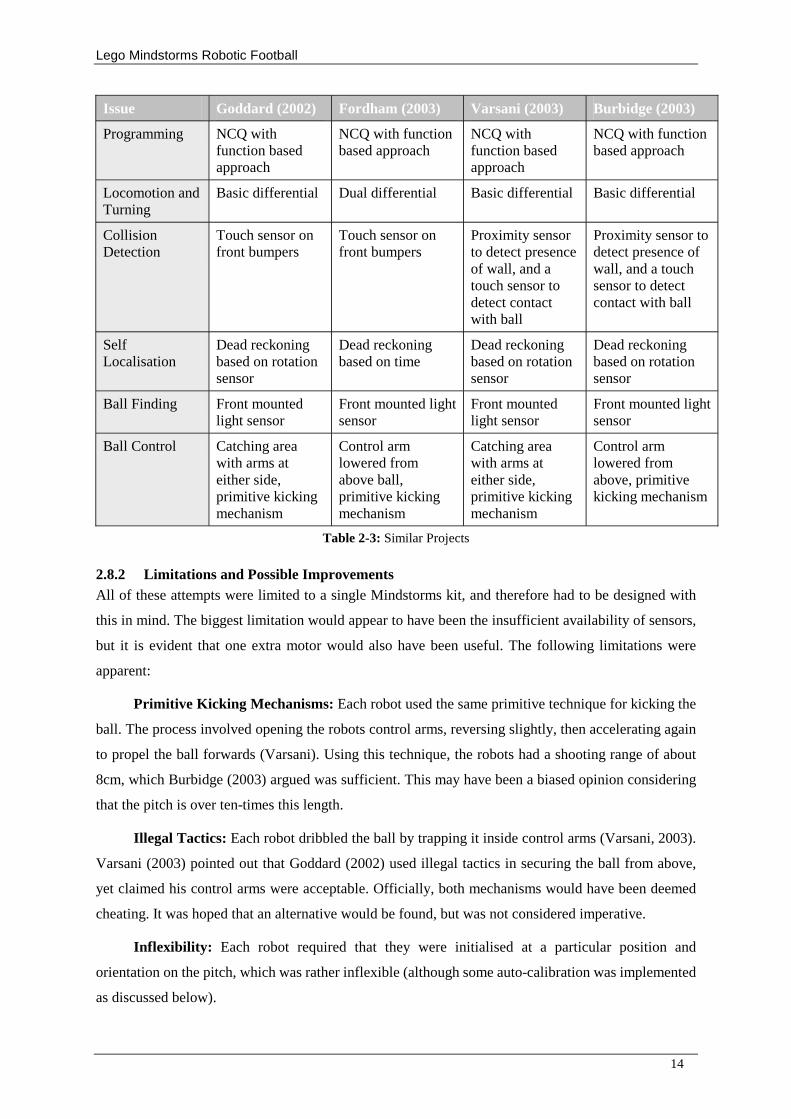
2.8.1 Summary The existing documentation for similar projects available on the Internet is generally poor, and
lacking in detail. Fortunately, the reports for four projects undertaken by previous final year students,
Goddard (2002), Fordham (2003), Varsani (2003), and Burbidge (2003) have however been useful.
Table 2-3 summarises the approach taken by each student.
Lego Mindstorms Robotic Football
14
Issue Goddard (2002) Fordham (2003) Varsani (2003) Burbidge (2003)
Programming NCQ with function based approach
NCQ with function based approach
NCQ with function based approach
NCQ with function based approach
Locomotion and Turning
Basic differential Dual differential Basic differential Basic differential
Collision Detection
Touch sensor on front bumpers
Touch sensor on front bumpers
Proximity sensor to detect presence of wall, and a touch sensor to detect contact with ball
Proximity sensor to detect presence of wall, and a touch sensor to detect contact with ball
Self Localisation
Dead reckoning based on rotation sensor
Dead reckoning based on time
Dead reckoning based on rotation sensor
Dead reckoning based on rotation sensor
Ball Finding Front mounted light sensor
Front mounted light sensor
Front mounted light sensor
Front mounted light sensor
Ball Control Catching area with arms at either side, primitive kicking mechanism
Control arm lowered from above ball, primitive kicking mechanism
Catching area with arms at either side, primitive kicking mechanism
Control arm lowered from above, primitive kicking mechanism
Table 2-3: Similar Projects
2.8.2 Limitations and Possible Improvements All of these attempts were limited to a single Mindstorms kit, and therefore had to be designed with
this in mind. The biggest limitation would appear to have been the insufficient availability of sensors,
but it is evident that one extra motor would also have been useful. The following limitations were
apparent:
Primitive Kicking Mechanisms: Each robot used the same primitive technique for kicking the
ball. The process involved opening the robots control arms, reversing slightly, then accelerating again
to propel the ball forwards (Varsani). Using this technique, the robots had a shooting range of about
8cm, which Burbidge (2003) argued was sufficient. This may have been a biased opinion considering
that the pitch is over ten-times this length.
Illegal Tactics: Each robot dribbled the ball by trapping it inside control arms (Varsani, 2003).
Varsani (2003) pointed out that Goddard (2002) used illegal tactics in securing the ball from above,
yet claimed his control arms were acceptable. Officially, both mechanisms would have been deemed
cheating. It was hoped that an alternative would be found, but was not considered imperative.
Inflexibility: Each robot required that they were initialised at a particular position and
orientation on the pitch, which was rather inflexible (although some auto-calibration was implemented
as discussed below).
Lego Mindstorms Robotic Football
15
Inaccurate Dead Reckoning: The dead reckoning techniques used in these projects were said
to work well, but this was perhaps a naive conclusion, as the robots were not tested in a real match
situation. In a real match, collisions between robots are the most likely cause of dead reckoning errors.
2.8.3 Areas of Interest These robots did demonstrate positive features too; for example they were all, to some extent, capable
of automatic calibration before a match started, allowing them to compensate for different pitch
surfaces, lighting conditions and so on. The ‘Future work’ chapters however, were the most
intriguing, as summarised below.
RCX Communication: Varsani (2003) introduced the notion of message passing between
robots, and explained how this can be done via infrared. He made a slight error when he states the
range of message values being from 0 to 255, as the actual minimum is 1 (Baum et al, 2001), but the
general discussion is good. He talked about what he calls “ distributing the workload” by having a
personal computer do some of the work, but he does not put forward the idea of having two RCXs on
a single robot. Burbidge (2003) includes a similar discussion but adds that the RCX 2 (as apposed to
RCX 1) is capable of serial data transfer. Unfortunately, the University of Leeds does not own a single
RCX 2.
Grey-scale Pitch: Varsani (2003) and Burbidge (2003) also experimented with using the grey
scale pitch to determine heading. Both concluded that the Mindstorms light sensors are not accurate
enough for the grey-scale pitch to be of great use, however it is unclear as to whether experimentation
was comprehensive. It is also quite possible that more accurate ‘homebrew’ light sensors would give
better results.
2.9 Project Methodology As this project is of an investigative nature rather than a typical project with end-users and
stakeholders, industry standards cannot be applied in full.
The waterfall model and waterfall model with iteration split development into seven stages (Bennett,
McRobb, Farmer, 2002), however only four are relevant to this project, as the others are concerned
with project stakeholders. The four relevant stages are systems engineering, design, construction, and
testing. The waterfall life cycle is so-called because it compares returning to a previously completed
phase to swimming up a waterfall. This idea is justified in many projects because their phases have
explicit deliverables for each stage on a fixed schedule. It is unsuitable in this case due to its
experimental nature. With this project, there needs to be possibility of refining any work done at any
stage. The waterfall model with iteration allows the developer to traverse back to a completed stage,
but at great cost, as each of the deliverables for each intermediary stage must be recompiled before
proceeding again, rendering this option unsuitable too.
Lego Mindstorms Robotic Football
16
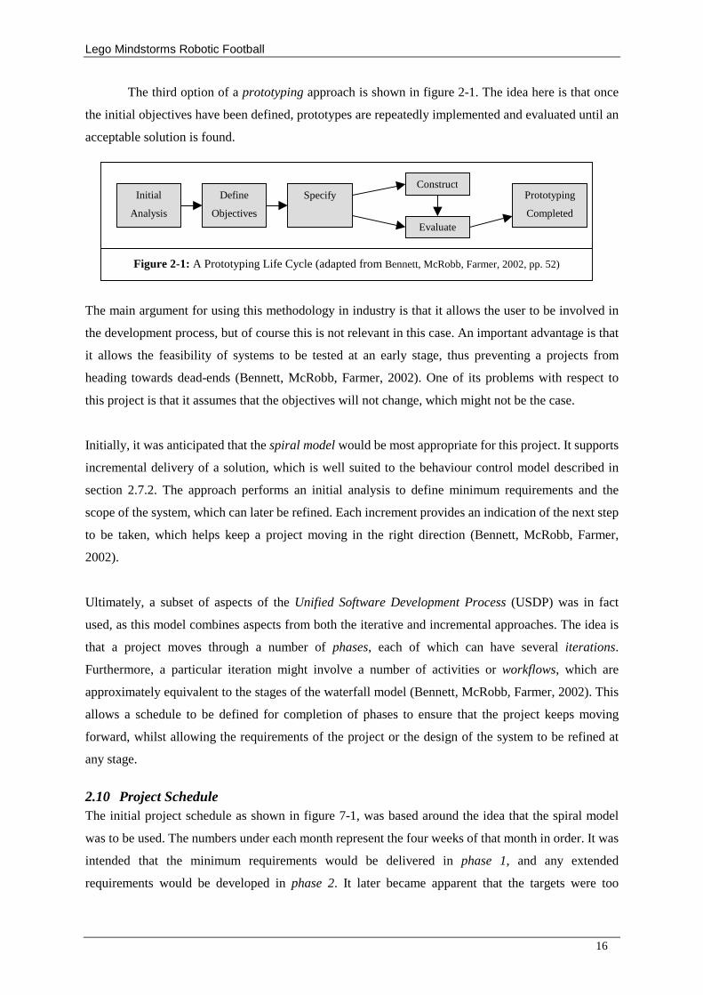
The third option of a prototyping approach is shown in figure 2-1. The idea here is that once
the initial objectives have been defined, prototypes are repeatedly implemented and evaluated until an
acceptable solution is found.
The main argument for using this methodology in industry is that it allows the user to be involved in
the development process, but of course this is not relevant in this case. An important advantage is that
it allows the feasibility of systems to be tested at an early stage, thus preventing a projects from
heading towards dead-ends (Bennett, McRobb, Farmer, 2002). One of its problems with respect to
this project is that it assumes that the objectives will not change, which might not be the case.
Initially, it was anticipated that the spiral model would be most appropriate for this project. It supports
incremental delivery of a solution, which is well suited to the behaviour control model described in
section 2.7.2. The approach performs an initial analysis to define minimum requirements and the
scope of the system, which can later be refined. Each increment provides an indication of the next step
to be taken, which helps keep a project moving in the right direction (Bennett, McRobb, Farmer,
2002).
Ultimately, a subset of aspects of the Unified Software Development Process (USDP) was in fact
used, as this model combines aspects from both the iterative and incremental approaches. The idea is
that a project moves through a number of phases, each of which can have several iterations.
Furthermore, a particular iteration might involve a number of activities or workflows, which are
approximately equivalent to the stages of the waterfall model (Bennett, McRobb, Farmer, 2002). This
allows a schedule to be defined for completion of phases to ensure that the project keeps moving
forward, whilst allowing the requirements of the project or the design of the system to be refined at
any stage.
2.10 Project Schedule The initial project schedule as shown in figure 7-1, was based around the idea that the spiral model
was to be used. The numbers under each month represent the four weeks of that month in order. It was
intended that the minimum requirements would be delivered in phase 1, and any extended
requirements would be developed in phase 2. It later became apparent that the targets were too
Initial
Analysis
Define
Objectives
Specify Construct
Evaluate
Prototyping
Completed
Figure 2-1: A Prototyping Life Cycle (adapted from Bennett, McRobb, Farmer, 2002, pp. 52)
Lego Mindstorms Robotic Football
17
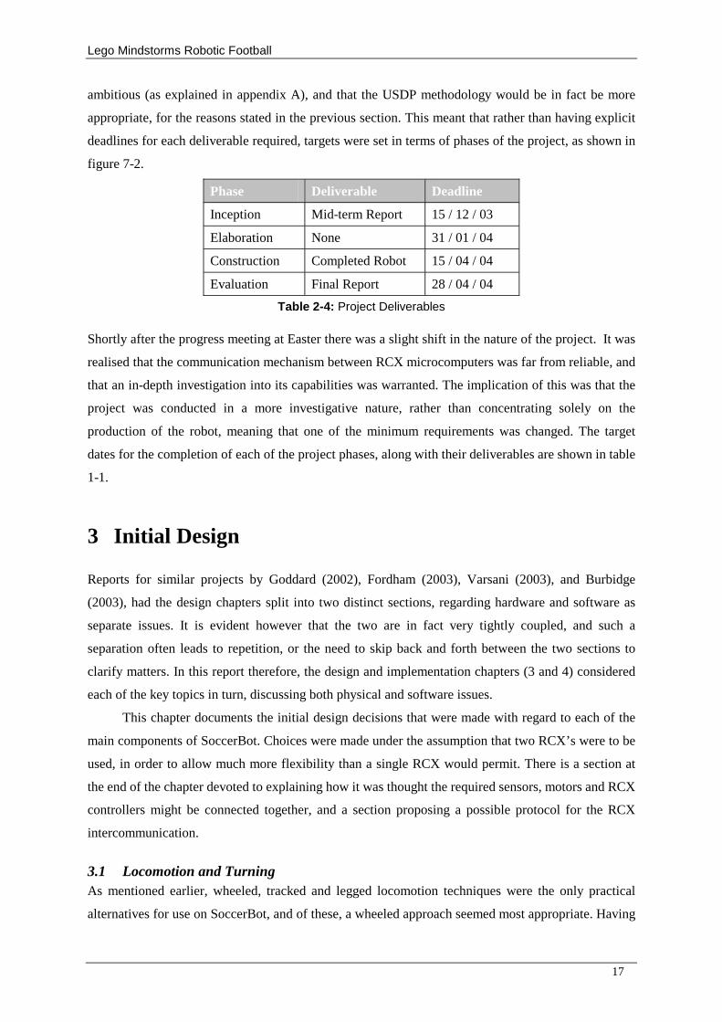
ambitious (as explained in appendix A), and that the USDP methodology would be in fact be more
appropriate, for the reasons stated in the previous section. This meant that rather than having explicit
deadlines for each deliverable required, targets were set in terms of phases of the project, as shown in
figure 7-2.
Phase Deliverable Deadline
Inception Mid-term Report 15 / 12 / 03
Elaboration None 31 / 01 / 04
Construction Completed Robot 15 / 04 / 04
Evaluation Final Report 28 / 04 / 04
Table 2-4: Project Deliverables
Shortly after the progress meeting at Easter there was a slight shift in the nature of the project. It was
realised that the communication mechanism between RCX microcomputers was far from reliable, and
that an in-depth investigation into its capabilities was warranted. The implication of this was that the
project was conducted in a more investigative nature, rather than concentrating solely on the
production of the robot, meaning that one of the minimum requirements was changed. The target
dates for the completion of each of the project phases, along with their deliverables are shown in table
1-1.
3 Initial Design
Reports for similar projects by Goddard (2002), Fordham (2003), Varsani (2003), and Burbidge
(2003), had the design chapters split into two distinct sections, regarding hardware and software as
separate issues. It is evident however that the two are in fact very tightly coupled, and such a
separation often leads to repetition, or the need to skip back and forth between the two sections to
clarify matters. In this report therefore, the design and implementation chapters (3 and 4) considered
each of the key topics in turn, discussing both physical and software issues.
This chapter documents the initial design decisions that were made with regard to each of the
main components of SoccerBot. Choices were made under the assumption that two RCX’ s were to be
used, in order to allow much more flexibility than a single RCX would permit. There is a section at
the end of the chapter devoted to explaining how it was thought the required sensors, motors and RCX
controllers might be connected together, and a section proposing a possible protocol for the RCX
intercommunication.
3.1 Locomotion and Turning As mentioned earlier, wheeled, tracked and legged locomotion techniques were the only practical
alternatives for use on SoccerBot, and of these, a wheeled approach seemed most appropriate. Having
Lego Mindstorms Robotic Football
18
considered the research findings, and after a little experimentation, it was decided that a dual
differential drive would be used. The examples of such drives in the literature generally ignore the
practicality of the layout of the gear chain; in order to clearly illustrate how the mechanism works, but
a more compact layout was planned for use on SoccerBot. See figure E-1 for an example of an non-
compact layout.
At a primitive level, the programming involved in locomotion is minimal. Two functions are required;
move and rotate. The move function turns off motor A whilst turning on motor B. Conversely the
rotate function turns off motor B whilst turning on motor A. Neither this description, nor the figure
suggests how wheel rotation might be monitored. This is explained in more detail in the next section.
3.2 Ball Finding The best ball finding technique that was found during the literature review was that used on Baum’ s
Scanbot (Baum, 2001). Given that up to six sensors and motors could be used on SoccerBot, the extra
resources required for the mechanism was not considered a problem. From this point on, the ball
finding mechanism is referred to simply as the ball finder.
For calibration purposes, a stopper is needed on the ball finder at some known angle of rotation.
Each time SoccerBot is activated, the ball finder needs to return to this position, before resetting the
rotation sensor and commencing the scanning operation. The reason for this is that the reading of the
rotation sensor is relative to the initial angle of the head, which is not necessarily the same each time
SoccerBot is activated. One method for aligning the ball finder in this way suggested by Baum et al
(2001) is to turn the head for a fixed amount of time, say t seconds, which is just greater than the time
it takes to rotate from one side of the stopper to the other. This is not optimal. In the worst case, the
head could be aligned perfectly to begin with, meaning that a time will be wasted. Baum et al (2001)
did not mention the better approach of simply turning the head until the rotation sensor reading
remains constant before resetting, which wastes less time.
There is a further improvement that was not suggested, which involves retaining the rotation
sensor reading at which the brightest light is observed during head alignment. If this value is
compared to the new reading obtained after the head has come to a halt, then the actual direction of
the observed bright light source can be calculated very simply, so that no time was wasted on start-up.
Scanbot’ s scanner covered a range of 270 degrees, but it was hoped that SoccerBot could cover
an angle closer to 360 degrees. A full circle was not considered possible at this stage because of the
need for a calibration stopper. The intention was to reduce the range of the scans as SoccerBot
approached the ball to allow a higher frequency of scans, resulting in a more up-to-date estimation of
ball direction at any time. It was thought that the light-level reading observed in the direction of the
ball might be used as a basis for an estimation of distance.
Lego Mindstorms Robotic Football
19
3.3 Self-Localisation As explained in the literature review, use of a video camera was not considered appropriate. Many
similar projects including those undertaken by Goddard (2002), Fordham (2003), Varsani (2003) and
Burbidge (2003), have used dead reckoning for self-localisation, and found it to be reasonably
accurate in most cases, providing collisions don’ t happen to occur. Very few of the reports for these
projects have boasted that their associated robot is capable of detecting and correcting dead reckoning
errors, and so an investigation into this topic was also undertaken.
In theory, when moving in a straight line, the distance travelled during n rotations of drive
wheels of circumference c, can be calculated by d = n * c. In practice however, the wheels “ slip”
against the pitch surface slightly, meaning the actual distance travelled is slightly less than this value
of d. Unfortunately, the extent of slippage is dependent on various factors, including the texture of the
pitch, and the type of wheels used. Calibration is therefore required whenever any of these factors
change. Slip also has a similar affect on rotational movement.
Providing the wheels are rotating at a constant rate, r say, the time taken for the wheels to
rotate n times is given by t = n / r. Two problems however arise from estimating distances from the
time in motion, with regard to dead reckoning accuracy. Firstly, the rate of rotation of wheels varies
with battery power and the pitch surface, and secondly, collisions may result in the wheels coming to
a standstill for a period, during which time, SoccerBot would be unaware that it is no longer in
motion. A partial solution is to use a rotation sensor to record the actual number of wheel rotations but
this still does not overcome the problem of slippage between the wheels and the pitch surface. The
Mindstorms rotation sensor is accurate to one sixteenth of a revolution, which is rather inaccurate. It
is hence necessary to gear up from the axle on which the wheels rotate in order to improve the
accuracy of the measure. Consider figure 3-0 on the previous page. If an eight-toothed gear is meshed
with G (which has twenty-four teeth), then wheel rotation can be monitored reasonably accurately. In
fact, recording the rotation of this smaller gear would measure increments as small as 1/48th of a
revolution (24 / 8 = 3, and 3 * 16 = 48). A minor loss in accuracy results from the latency between
gear G changing direction, and the meshed gear following suit, but this was not expected to cause a
problem.
The trigonometric functions required for dead reckoning are not provided as standard in NQC,
and so would have to be implemented manually. Previous projects have included the code used for
dead-reckoning purposes, and it was hoped that this code would be transferable to SoccerBot. An
important point that had to be taken into account was that NQC does not support floating point
variables. The actual cosine and sin values must be multiplied be a large value (1000 is sensible), and
then rounded to the nearest integer value. Of course these values must be scaled back down before
any trigonometric calculations are performed.
Lego Mindstorms Robotic Football
20
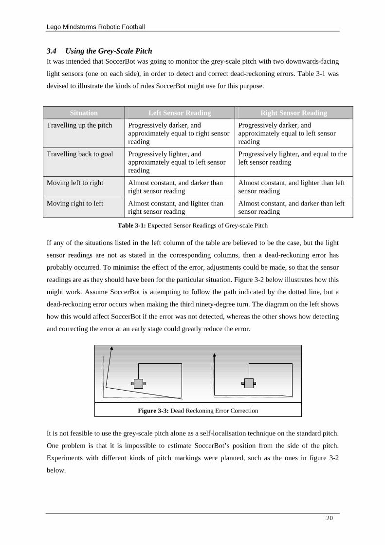
3.4 Using the Grey-Scale Pitch It was intended that SoccerBot was going to monitor the grey-scale pitch with two downwards-facing
light sensors (one on each side), in order to detect and correct dead-reckoning errors. Table 3-1 was
devised to illustrate the kinds of rules SoccerBot might use for this purpose.
Situation Left Sensor Reading Right Sensor Reading
Travelling up the pitch Progressively darker, and approximately equal to right sensor reading
Progressively darker, and approximately equal to left sensor reading
Travelling back to goal Progressively lighter, and approximately equal to left sensor reading
Progressively lighter, and equal to the left sensor reading
Moving left to right Almost constant, and darker than right sensor reading
Almost constant, and lighter than left sensor reading
Moving right to left Almost constant, and lighter than right sensor reading
Almost constant, and darker than left sensor reading
Table 3-1: Expected Sensor Readings of Grey-scale Pitch
If any of the situations listed in the left column of the table are believed to be the case, but the light
sensor readings are not as stated in the corresponding columns, then a dead-reckoning error has
probably occurred. To minimise the effect of the error, adjustments could be made, so that the sensor
readings are as they should have been for the particular situation. Figure 3-2 below illustrates how this
might work. Assume SoccerBot is attempting to follow the path indicated by the dotted line, but a
dead-reckoning error occurs when making the third ninety-degree turn. The diagram on the left shows
how this would affect SoccerBot if the error was not detected, whereas the other shows how detecting
and correcting the error at an early stage could greatly reduce the error.
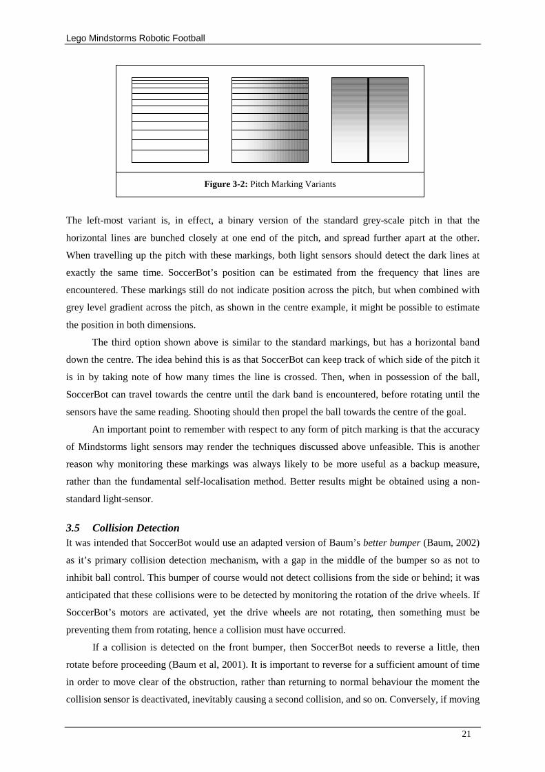
It is not feasible to use the grey-scale pitch alone as a self-localisation technique on the standard pitch.
One problem is that it is impossible to estimate SoccerBot’ s position from the side of the pitch.
Experiments with different kinds of pitch markings were planned, such as the ones in figure 3-2
below.
Figure 3-3: Dead Reckoning Error Correction
Lego Mindstorms Robotic Football
21
The left-most variant is, in effect, a binary version of the standard grey-scale pitch in that the
horizontal lines are bunched closely at one end of the pitch, and spread further apart at the other.
When travelling up the pitch with these markings, both light sensors should detect the dark lines at
exactly the same time. SoccerBot’ s position can be estimated from the frequency that lines are
encountered. These markings still do not indicate position across the pitch, but when combined with
grey level gradient across the pitch, as shown in the centre example, it might be possible to estimate
the position in both dimensions.
The third option shown above is similar to the standard markings, but has a horizontal band
down the centre. The idea behind this is as that SoccerBot can keep track of which side of the pitch it
is in by taking note of how many times the line is crossed. Then, when in possession of the ball,
SoccerBot can travel towards the centre until the dark band is encountered, before rotating until the
sensors have the same reading. Shooting should then propel the ball towards the centre of the goal.
An important point to remember with respect to any form of pitch marking is that the accuracy
of Mindstorms light sensors may render the techniques discussed above unfeasible. This is another
reason why monitoring these markings was always likely to be more useful as a backup measure,
rather than the fundamental self-localisation method. Better results might be obtained using a non-
standard light-sensor.
3.5 Collision Detection It was intended that SoccerBot would use an adapted version of Baum’ s better bumper (Baum, 2002)
as it’ s primary collision detection mechanism, with a gap in the middle of the bumper so as not to
inhibit ball control. This bumper of course would not detect collisions from the side or behind; it was
anticipated that these collisions were to be detected by monitoring the rotation of the drive wheels. If
SoccerBot’ s motors are activated, yet the drive wheels are not rotating, then something must be
preventing them from rotating, hence a collision must have occurred.
If a collision is detected on the front bumper, then SoccerBot needs to reverse a little, then
rotate before proceeding (Baum et al, 2001). It is important to reverse for a sufficient amount of time
in order to move clear of the obstruction, rather than returning to normal behaviour the moment the
collision sensor is deactivated, inevitably causing a second collision, and so on. Conversely, if moving
Figure 3-2: Pitch Marking Variants
Lego Mindstorms Robotic Football
22
backwards and the wheels stop rotating, then SoccerBot needs to move forward for a short distance
before continuing. If a collision occurs during rotation however, then the solution is not quite so clear,
as the obstruction may be located at either side of SoccerBot. Hopefully moving forwards slightly will
clear the obstruction, but if not, reversing should solve definitely solve the problem, or else SoccerBot
is must be stuck.
3.6 Ball Control The most important aspect of ball control is dribbling; allowing the ball to be moved from one point
on the pitch to another, more desirable position. Three considerations to this end were:
1. What kind of physical mechanism would be used to control the ball?
2. What low-level movements would be required to move the ball around using this mechanism?
3. Where should the ball be moved to, and what path should be taken to get there?
Clamping the ball with arms is illegal as explained in the literature review. It was the intention that
SoccerBot would instead have looser control arms that guide the ball along. This approach is simpler,
and frees up another motor, but means that SoccerBot will have to be more skilful when moving with
the ball in order to maintain possession. It was thought that applying padding to the front of
SoccerBot may reduce the bounce, and that decelerating when approaching the ball might also help
when SoccerBot is attempting to gain possession. It was imagined that loosing possession might not
actually prove to be too disastrous if the proposed ball finder was used, as the ball could quickly be
found again and reclaimed, which would be analogous to dribbling the ball in a real football match.
The first consideration regarding the second question above is how SoccerBot’ s locomotion
mechanism could be best utilised to keep control. Goddard (2003, pp. 26), found that by rotating
about one of the wheels (rather than the centre of the robot), he was able to maintain better control of
the ball. He did not did not suggest how one might compensate for this in the dead reckoning system,
and without doing so his robots calculations would have flawed. The appropriate modifications
required to the code would in fact be too complicated, so this idea was ruled out.
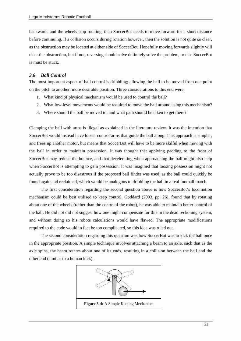
The second consideration regarding this question was how SoccerBot was to kick the ball once
in the appropriate position. A simple technique involves attaching a beam to an axle, such that as the
axle spins, the beam rotates about one of its ends, resulting in a collision between the ball and the
other end (similar to a human kick).
Figure 3-4: A Simple Kicking Mechanism
Lego Mindstorms Robotic Football
23
There are two obvious disadvantages with this mechanism. Firstly, a relatively large space is required
in order to spin a beam in this manner. Assuming the figure above is approximately to scale, the
length of the beam would have to be eight inches (two times the diameter of the ball). Secondly, the
beam would have to pick up enough speed to propel the ball in less than one rotation of the axle,
which is hardly likely with the limitations of the Lego motor.
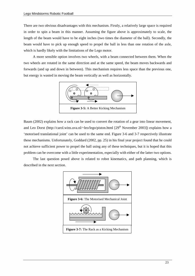
A more sensible option involves two wheels, with a beam connected between them. When the
two wheels are rotated in the same direction and at the same speed, the beam moves backwards and
forwards (and up and down in between). This mechanism requires less space than the previous one,
but energy is wasted in moving the beam vertically as well as horizontally.
Baum (2002) explains how a rack can be used to convert the rotation of a gear into linear movement,
and Leo Dorst (http://carol.wins.uva.nl/~leo/lego/piston.html [29th November 2003]) explains how a
‘motorised translational joint’ can be used to the same end. Figure 3-6 and 3-7 respectively illustrate
these mechanisms. Unfortunately, Goddard (2002, pp. 25) in his final year project found that he could
not achieve sufficient power to propel the ball using any of these techniques, but it is hoped that this
problem can be overcome with a little experimentation, especially with either of the latter two options.
The last question posed above is related to robot kinematics, and path planning, which is
described in the next section.
Figure 3-5: A Better Kicking Mechanism
Figure 3-6: The Motorised Mechanical Joint
Figure 3-7: The Rack as a Kicking Mechanism
Lego Mindstorms Robotic Football
24
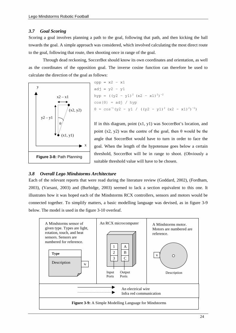
3.7 Goal Scoring Scoring a goal involves planning a path to the goal, following that path, and then kicking the ball
towards the goal. A simple approach was considered, which involved calculating the most direct route
to the goal, following that route, then shooting once in range of the goal.
Through dead reckoning, SoccerBot should know its own coordinates and orientation, as well
as the coordinates of the opposition goal. The inverse cosine function can therefore be used to
calculate the direction of the goal as follows:
opp = x2 – x1
adj = y2 – y1
hyp = ((y2 – y1)2 (x2 – x1)2)-2
������������� �� �������-1(y2 – y1 / ((y2 – y1)2 (x2 – x1)2)-2)
If in this diagram, point (x1, y1) was SoccerBot’ s location, and
point (x2, y2) wa�� ���� �������� ������ �� ��������� ����� ����angle that SoccerBot would have to turn in order to face the
goal. When the length of the hypotenuse goes below a certain
threshold, SoccerBot will be in range to shoot. (Obviously a
suitable threshold value will have to be chosen.
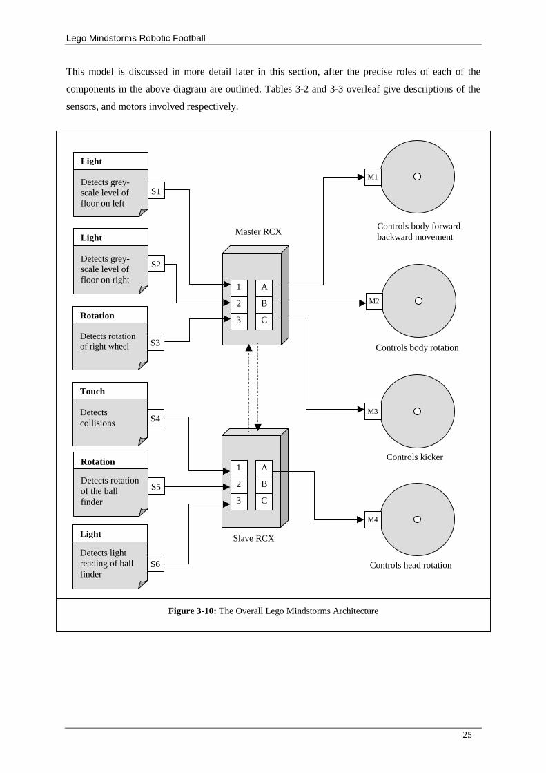
3.8 Overall Lego Mindstorms Architecture Each of the relevant reports that were read during the literature review (Goddard, 2002), (Fordham,
2003), (Varsani, 2003) and (Burbidge, 2003) seemed to lack a section equivalent to this one. It
illustrates how it was hoped each of the Mindstorms RCX controllers, sensors and motors would be
connected together. To simplify matters, a basic modelling language was devised, as in figure 3-9
below. The model is used in the figure 3-10 overleaf.
A Mindstorms sensor of given type. Types are light, rotation, touch, and heat sensors. Sensors are numbered for reference.
An RCX microcomputer A Mindstorms motor. Motors are numbered are reference.
Description
Type
N
Figure 3-9: A Simple Modelling Language for Mindstorms
X
Description Output Ports
Input Ports
1
2
3
A
B
C
An electrical wire Infra red communication
(x2, y2)
(x1, y1)
� y2 – y1
x2 – x1
y
x
Figure 3-8: Path Planning
Lego Mindstorms Robotic Football
25
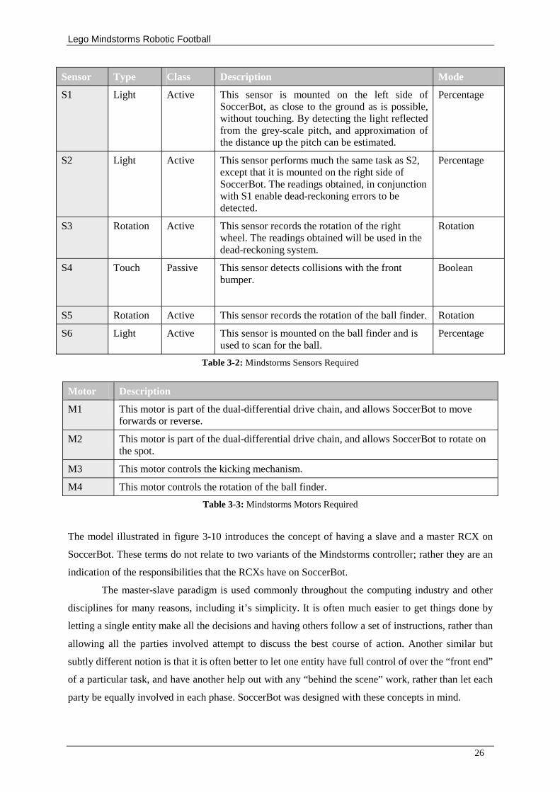
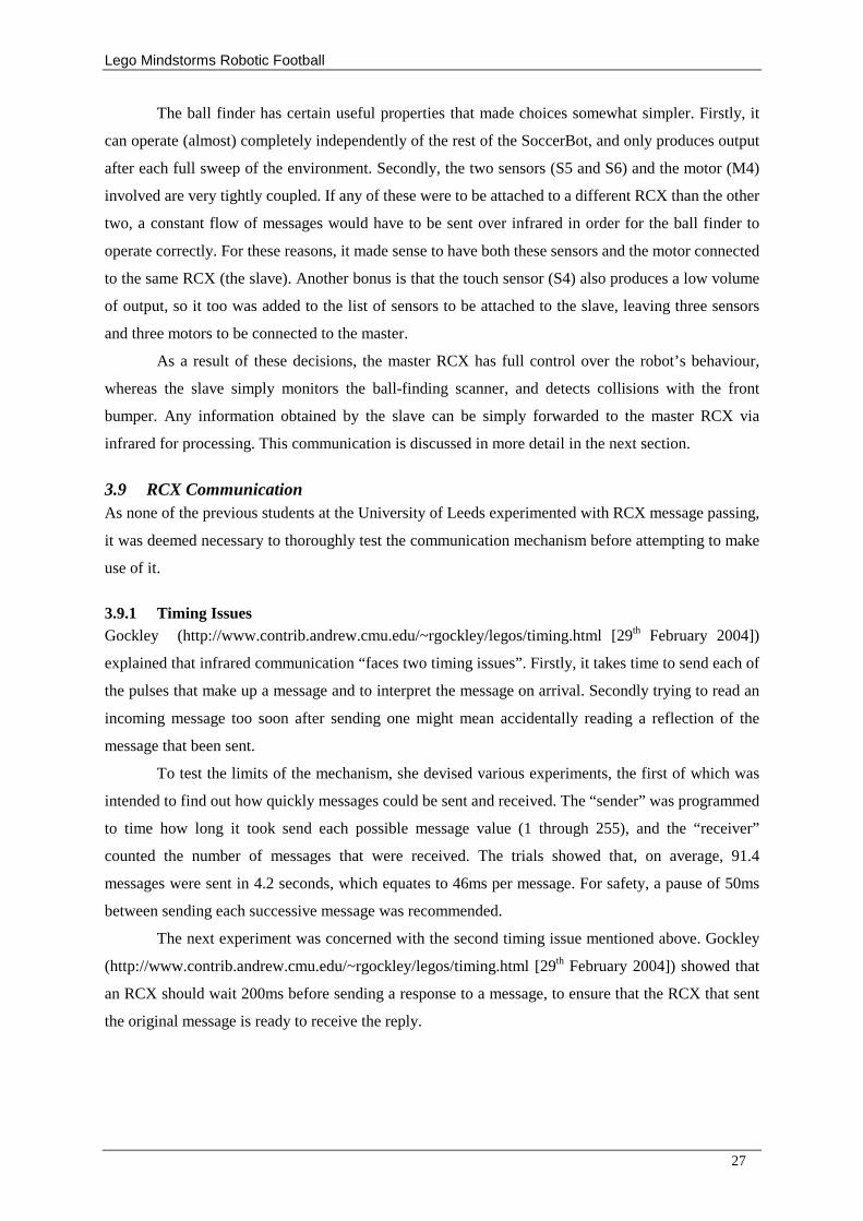
This model is discussed in more detail later in this section, after the precise roles of each of the
components in the above diagram are outlined. Tables 3-2 and 3-3 overleaf give descriptions of the
sensors, and motors involved respectively.
Controls body forward-backward movement
Controls body rotation
Controls head rotation
Controls kicker
1
2
3
A
B
C
Type Detects grey-scale level of floor on left
Light
S1
Type Detects grey-scale level of floor on right
Light
S2
Type Detects collisions
Touch
S4
Type Detects rotation of the ball finder
Rotation
S5
Type Detects light reading of ball finder
Light
S6
M1
M2
M4
M3
Type Detects rotation of right wheel
Rotation
S3
1
2
3
A
B
C
Slave RCX
Master RCX
Figure 3-10: The Overall Lego Mindstorms Architecture
Lego Mindstorms Robotic Football
26
Sensor Type Class Description Mode
S1 Light Active This sensor is mounted on the left side of SoccerBot, as close to the ground as is possible, without touching. By detecting the light reflected from the grey-scale pitch, and approximation of the distance up the pitch can be estimated.
Percentage
S2 Light Active This sensor performs much the same task as S2, except that it is mounted on the right side of SoccerBot. The readings obtained, in conjunction with S1 enable dead-reckoning errors to be detected.
Percentage
S3 Rotation Active This sensor records the rotation of the right wheel. The readings obtained will be used in the dead-reckoning system.
Rotation
S4 Touch Passive This sensor detects collisions with the front bumper.
Boolean
S5 Rotation Active This sensor records the rotation of the ball finder. Rotation
S6 Light Active This sensor is mounted on the ball finder and is used to scan for the ball.
Percentage
Table 3-2: Mindstorms Sensors Required
Motor Description
M1 This motor is part of the dual-differential drive chain, and allows SoccerBot to move forwards or reverse.
M2 This motor is part of the dual-differential drive chain, and allows SoccerBot to rotate on the spot.
M3 This motor controls the kicking mechanism.
M4 This motor controls the rotation of the ball finder.
Table 3-3: Mindstorms Motors Required
The model illustrated in figure 3-10 introduces the concept of having a slave and a master RCX on
SoccerBot. These terms do not relate to two variants of the Mindstorms controller; rather they are an
indication of the responsibilities that the RCXs have on SoccerBot.
The master-slave paradigm is used commonly throughout the computing industry and other
disciplines for many reasons, including it’ s simplicity. It is often much easier to get things done by
letting a single entity make all the decisions and having others follow a set of instructions, rather than
allowing all the parties involved attempt to discuss the best course of action. Another similar but
subtly different notion is that it is often better to let one entity have full control of over the “ front end”
of a particular task, and have another help out with any “ behind the scene” work, rather than let each
party be equally involved in each phase. SoccerBot was designed with these concepts in mind.
Lego Mindstorms Robotic Football
27
The ball finder has certain useful properties that made choices somewhat simpler. Firstly, it
can operate (almost) completely independently of the rest of the SoccerBot, and only produces output
after each full sweep of the environment. Secondly, the two sensors (S5 and S6) and the motor (M4)
involved are very tightly coupled. If any of these were to be attached to a different RCX than the other
two, a constant flow of messages would have to be sent over infrared in order for the ball finder to
operate correctly. For these reasons, it made sense to have both these sensors and the motor connected
to the same RCX (the slave). Another bonus is that the touch sensor (S4) also produces a low volume
of output, so it too was added to the list of sensors to be attached to the slave, leaving three sensors
and three motors to be connected to the master.
As a result of these decisions, the master RCX has full control over the robot’ s behaviour,
whereas the slave simply monitors the ball-finding scanner, and detects collisions with the front
bumper. Any information obtained by the slave can be simply forwarded to the master RCX via
infrared for processing. This communication is discussed in more detail in the next section.
3.9 RCX Communication As none of the previous students at the University of Leeds experimented with RCX message passing,
it was deemed necessary to thoroughly test the communication mechanism before attempting to make
use of it.
3.9.1 Timing Issues Gockley (http://www.contrib.andrew.cmu.edu/~rgockley/legos/timing.html [29th February 2004])
explained that infrared communication “ faces two timing issues” . Firstly, it takes time to send each of
the pulses that make up a message and to interpret the message on arrival. Secondly trying to read an
incoming message too soon after sending one might mean accidentally reading a reflection of the
message that been sent.
To test the limits of the mechanism, she devised various experiments, the first of which was
intended to find out how quickly messages could be sent and received. The “ sender” was programmed
to time how long it took send each possible message value (1 through 255), and the “ receiver”
counted the number of messages that were received. The trials showed that, on average, 91.4
messages were sent in 4.2 seconds, which equates to 46ms per message. For safety, a pause of 50ms
between sending each successive message was recommended.
The next experiment was concerned with the second timing issue mentioned above. Gockley
(http://www.contrib.andrew.cmu.edu/~rgockley/legos/timing.html [29th February 2004]) showed that
an RCX should wait 200ms before sending a response to a message, to ensure that the RCX that sent
the original message is ready to receive the reply.
Lego Mindstorms Robotic Football
28
3.9.2 Reliability Issues Gockley did not conduct experiments to test the reliability of the mechanism under different
conditions, so this was done as part of this project. The sender was programmed to send out each of
the possible message values, with a pause of 50ms (as suggested above) between each consecutive
send, and the receiver simply counted how many messages it received. The results of these
experiments can be found in tables C-4 and C-5. The conclusion drawn was that irrespective of how
two RCXs are positioned, reliability of message passing is not guaranteed. The best results, as one
might imagine, were obtained when the RCXs were close together, and facing each other, however
reservations would still have to be made for messages getting lost.
3.9.3 Protocol Issues One implication of the design was that the protocol required for communication protocol between the
two RCXs did not need to be over-complex. It was anticipated at an early stage that the single byte
infrared messages supported as standard would in fact be sufficient. Gockley
(http://www.contrib.andrew.cmu.edu/~rgockley/legos/index.html [29th February 2004]) on her web
site on RCX communication suggested a less primitive protocol that could have been used which
would have allowed longer messages to be sent if required, but was not considered necessary.
The intention was to allow two classes of messages to be sent from the slave RCX to the
master; a large range of values reserved for ball direction indication, and a small range reserved for
special messages, such as collision alerts, or message acknowledgements (ACKs). It was expected
that up to about 9 special messages might ultimately be needed. These were allotted message values
of 1 to 9, leaving messages 10 to 255 for ball direction indicators.
Ball direction indication messages need to be sent after each scan of the ball finder, to keep
the master RCX up-to-date. As there are 360 degrees in a complete circle, but only 245 message
values available, some fraction of the ball direction has to be sent, rather than the angle in degrees.
Obviously, the master is required to scale messages values back up in order to calculate the actual
direction of the ball.
It initially appeared sensible to map the ball direction to as large a range of message values as
possible (10 to 255). This idea was later dismissed, because it was realised that this would have in fact
resulted in unnecessary loss of accuracy. The reason for this is that the ball finder’ s rotation sensor is
accurate to some fraction of a full circle (1/56th as it turned out), and scaling these fractions to the
nearest 1/245th (as would be required) would result in rounding errors. A similar error would also have
occurred when the message was translated by the master once it was received. The intension was
therefore to send the actual ball finder rotation sensor reading, added to some known offset (so as not
to overlap with the special messages 1 to 9). At this point, the offset was set to 10, so that 0 would
map to 10, 1 would map to 11, and so on.
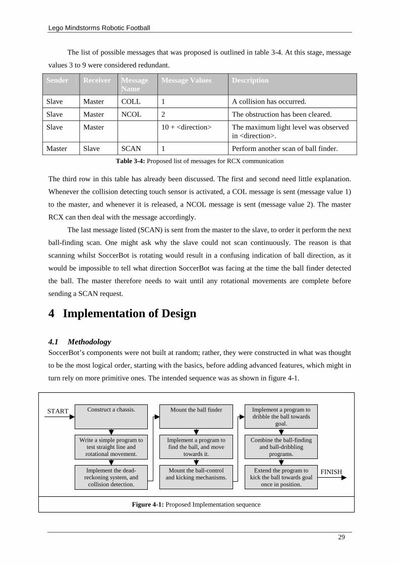
Lego Mindstorms Robotic Football
29
The list of possible messages that was proposed is outlined in table 3-4. At this stage, message
values 3 to 9 were considered redundant.
Sender Receiver Message Name
Message Values Description
Slave Master COLL 1 A collision has occurred.
Slave Master NCOL 2 The obstruction has been cleared.
Slave Master 10 + <direction> The maximum light level was observed in <direction>.
Master Slave SCAN 1 Perform another scan of ball finder.
Table 3-4: Proposed list of messages for RCX communication
The third row in this table has already been discussed. The first and second need little explanation.
Whenever the collision detecting touch sensor is activated, a COL message is sent (message value 1)
to the master, and whenever it is released, a NCOL message is sent (message value 2). The master
RCX can then deal with the message accordingly.
The last message listed (SCAN) is sent from the master to the slave, to order it perform the next
ball-finding scan. One might ask why the slave could not scan continuously. The reason is that
scanning whilst SoccerBot is rotating would result in a confusing indication of ball direction, as it
would be impossible to tell what direction SoccerBot was facing at the time the ball finder detected
the ball. The master therefore needs to wait until any rotational movements are complete before
sending a SCAN request.
4 Implementation of Design
4.1 Methodology SoccerBot’ s components were not built at random; rather, they were constructed in what was thought
to be the most logical order, starting with the basics, before adding advanced features, which might in
turn rely on more primitive ones. The intended sequence was as shown in figure 4-1.
Figure 4-1: Proposed Implementation sequence
Construct a chassis.
Write a simple program to test straight line and rotational movement.
Implement the dead-reckoning system, and
collision detection.
Mount the ball finder
Implement a program to find the ball, and move
towards it.
Mount the ball-control and kicking mechanisms.
Implement a program to dribble the ball towards
goal.
Combine the ball-finding and ball-dribbling
programs.
Extend the program to kick the ball towards goal
once in position.
START
FINISH
Lego Mindstorms Robotic Football
30
The actual sequence followed was slightly different, as the collision detection mechanism was added
after the ball finder because it was decided that the ball finder had greater priority.
4.2 Locomotion and Turning The locomotion mechanism turned out to be one of the most problematic for various reasons. Firstly,
having two RCX’ s along with the associated extra motors, sensors and batteries, meant that
SoccerBot’ s weight became a problem. With the first few prototype mechanisms, the Mindstorms
motors struggled to move SoccerBot at even the slowest of speeds, and various modifications were
tested to improve the situation.
The gear trains used to drive the robot in the first prototype chassis left much to be desired, as it
was difficult to turn the gear attached to the motor, even without any weight applied to the wheels.
This was mainly attributed to simply having too many gears involved in the mechanism, but it was
noticed that the flimsy construction also meant that axles were being bent unnecessarily, which also
contributed to the problem. The initial reaction to this observation was to gear down the output from
the motors to produce increased torque (Baum 2002). This of course had the side effect of slowing
down the maximum possible speed of wheel rotation, but at least this modification meant that
SoccerBot could keep going for more than a few minutes.
The six AA batteries were found to contribute most of the weight of the RCX’ s. One idea was
to replace them with a much lighter power source. Each RCX has an external input to allow it to be
powered by a mains adapter. Using an adapter was obviously impractical as it would require a cable
to transfer power to SoccerBot, but with a suitable cable, it was possible to use so-called 9-volt
“ square batteries” as a portable power source. This reduced the weight, but it did not help as these
batteries were quickly drained of power. Experiments showed that using a more a more powerful type
of battery helped, but unfortunately, such batteries were too expensive to use for extensive testing as
was required for this project.
The solution was to improve the efficiency of the differential drive itself. In fact, the
mechanism was revamped several times over a period of a week, and eventually an acceptable
solution was found, which required fewer gears and was less flimsy, allowing SoccerBot to travel at
similar velocities to other Soccer-playing robots. At no point was the dual differential drive dismissed,
as it was hoped that it would ultimately lead to a more impressive robot. This did put the project
behind schedule, but would prove to save time later on.
4.3 Self –Localisation Two parameters have to be acquired before dead reckoning is possible, in order to be able to relate
wheel rotation measurements to actual movement in a particular environment. One value is needed to
estimate distances travelled in a straight line, and a second is needed to estimate degrees of rotation. It
was hoped that ultimately, these values could be calculated by some calibration routine before each
match, but initially they were hard-coded into SoccerBot for a particular surface texture, Linoleum. In
Lego Mindstorms Robotic Football
31
order to obtain the first of these values, SoccerBot was programmed to travel in a straight line, and
stopped manually having travelled two metres (according to floor markings). Halving the final
rotation sensor reading gives the number of rotations in one metre, and dividing by one hundred
relates to two centimetres and so on. To improve accuracy, an average of the results of five such
experiments was taken to be the correct value. The offsets to either side of the intended path were also
noted, and averaged for future evaluation. The results are summarised in
table C-1. A similar experiment was performed for rotational movement. This time, SoccerBot was
halted after ten full revolutions. The results are summarised in table C-3.
The trigonometric functions were based on the results of these experiments. It was decided that
code from previous projects should not be used after all, because using them would require translating
fractions of 136 (1662 / 10) to degrees, which would result in unnecessary loss of accuracy. Instead,
exact sin and cosine values were calculated for 360 * (n/136) for each n between 0 and 136, scaled by
1000 and hard-coded into SoccerBot as a switch statement within a function. Imagine the sin value
corresponding to a rotation sensor reading of 80 is required, then the implemented sin function needs
called with an argument of 80, which would return the previously stored real value of
1000 * sin (360 * (80/136)). In other words, a new angular measurement has been introduced where
an angle of 136 is equivalent to 360 degrees. For clarity, this new measurement for angles will be
referred to as SoccerBot degrees (or SB-degrees) throughout the remainder of the report. The
algorithm for rotation is as follows:
1. If the angle is less than 180 degrees:
a. Turn the rotation motor on in reverse at full speed.
b. Just before reaching the intended angle, halve the speed of the motor.
c. Once the intended angle is reached, turn off the motor, and finish.
2. If the angle is more than 180 degrees:
a. Turn the rotation motor on forwards at full speed.
b. Just before reaching the intended angle, halve the speed of the motor.
c. Once the intended angle is reached, turn off the motor, and finish.
3. Update orientation variable, and normalise.
4. Call the trigonometry function.
Steps 1b and 2b were introduced to prevent SoccerBot’ s momentum from causing overrun on the
rotation. Previous projects such as Burbidge (2003) solved this problem by reversing the motor
momentarily after overrun has occurred, but it was decided that this was not an optimal solution, as
the extent of overrun depends on the amount of momentum built up. The term normalise in step 3
refers to the mapping of angles out of the range of 0 to 360 degrees to equivalent angles inside the
range. As an example, -90 degrees would be mapped to 270-degrees. The algorithm for forwards
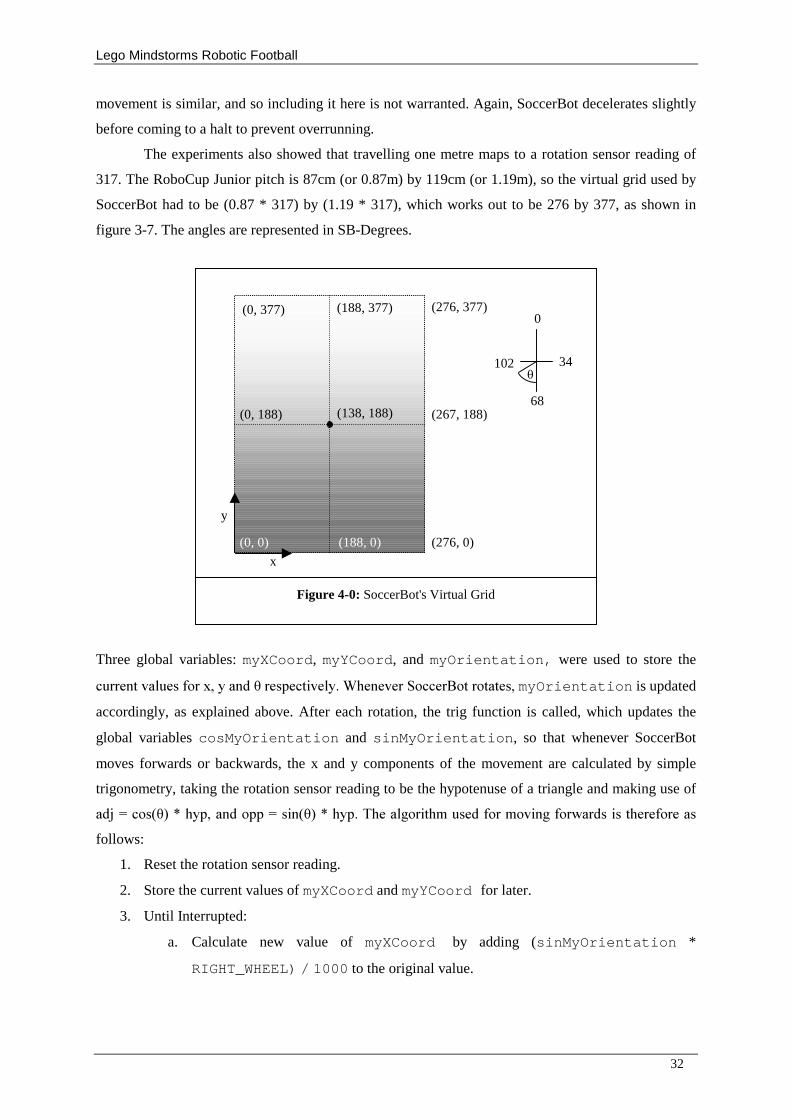
Lego Mindstorms Robotic Football
32
movement is similar, and so including it here is not warranted. Again, SoccerBot decelerates slightly
before coming to a halt to prevent overrunning.
The experiments also showed that travelling one metre maps to a rotation sensor reading of
317. The RoboCup Junior pitch is 87cm (or 0.87m) by 119cm (or 1.19m), so the virtual grid used by
SoccerBot had to be (0.87 * 317) by (1.19 * 317), which works out to be 276 by 377, as shown in
figure 3-7. The angles are represented in SB-Degrees.
Three global variables: myXCoord, myYCoord, and myOrientation, were used to store the
�������������� ����������������������������������� ����� ��� ������myOrientation is updated
accordingly, as explained above. After each rotation, the trig function is called, which updates the
global variables cosMyOrientation and sinMyOrientation, so that whenever SoccerBot
moves forwards or backwards, the x and y components of the movement are calculated by simple
trigonometry, taking the rotation sensor reading to be the hypotenuse of a triangle and making use of
������ ��������������� ����������������������� ����!������� ��! ��� �� �"������������� �����follows:
1. Reset the rotation sensor reading.
2. Store the current values of myXCoord and myYCoord for later.
3. Until Interrupted:
a. Calculate new value of myXCoord by adding (sinMyOrientation *
RIGHT_WHEEL) / 1000 to the original value.
(276, 377)
(188, 0)
(0, 188)
(0, 0)
(267, 188)
(188, 377) (0, 377)
(276, 0)
68
102
0
34 �
Figure 4-0: SoccerBot's Virtual Grid
x
y
(138, 188)
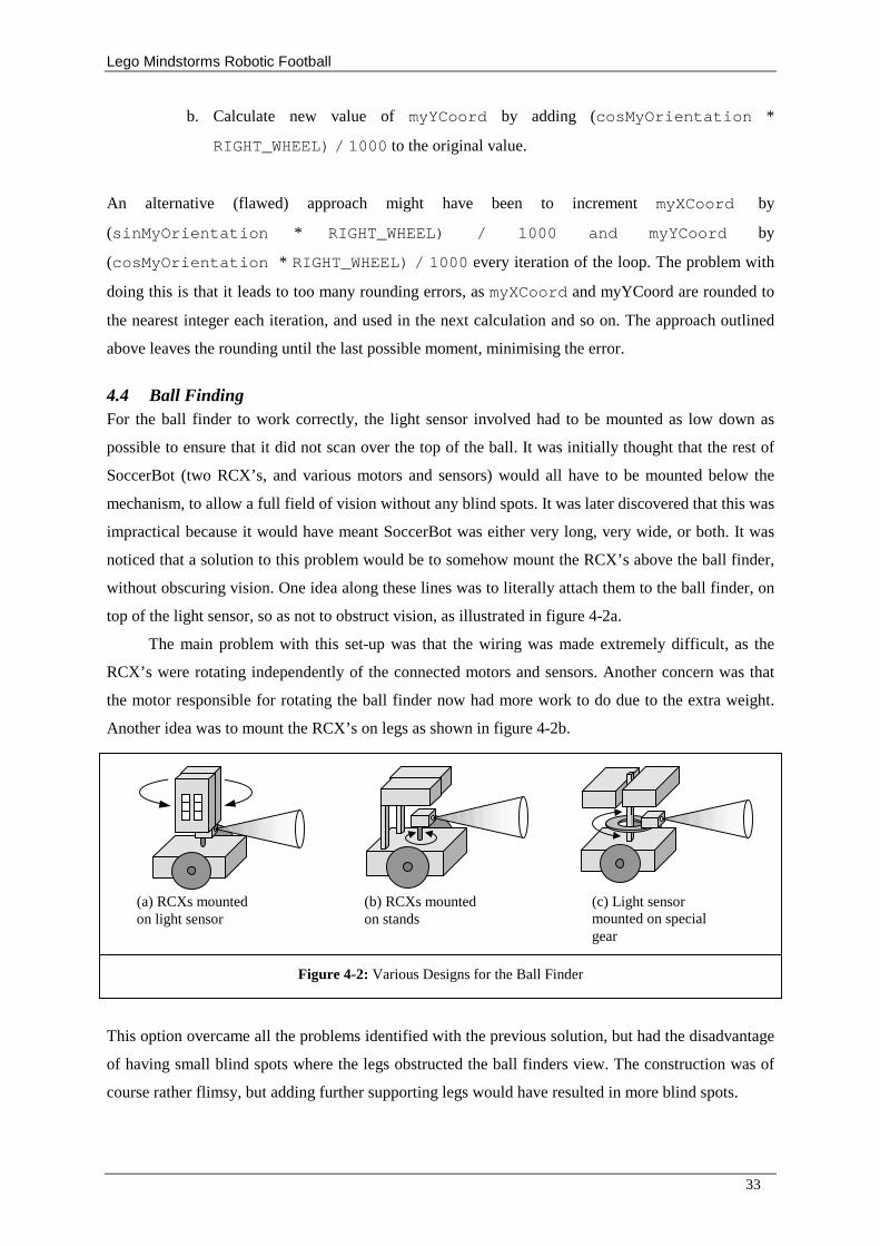
Lego Mindstorms Robotic Football
33
b. Calculate new value of myYCoord by adding (cosMyOrientation *
RIGHT_WHEEL) / 1000 to the original value.
An alternative (flawed) approach might have been to increment myXCoord by
(sinMyOrientation * RIGHT_WHEEL) / 1000 and myYCoord by
(cosMyOrientation * RIGHT_WHEEL) / 1000 every iteration of the loop. The problem with
doing this is that it leads to too many rounding errors, as myXCoord and myYCoord are rounded to
the nearest integer each iteration, and used in the next calculation and so on. The approach outlined
above leaves the rounding until the last possible moment, minimising the error.
4.4 Ball Finding For the ball finder to work correctly, the light sensor involved had to be mounted as low down as
possible to ensure that it did not scan over the top of the ball. It was initially thought that the rest of
SoccerBot (two RCX’ s, and various motors and sensors) would all have to be mounted below the
mechanism, to allow a full field of vision without any blind spots. It was later discovered that this was
impractical because it would have meant SoccerBot was either very long, very wide, or both. It was
noticed that a solution to this problem would be to somehow mount the RCX’ s above the ball finder,
without obscuring vision. One idea along these lines was to literally attach them to the ball finder, on
top of the light sensor, so as not to obstruct vision, as illustrated in figure 4-2a.
The main problem with this set-up was that the wiring was made extremely difficult, as the
RCX’ s were rotating independently of the connected motors and sensors. Another concern was that
the motor responsible for rotating the ball finder now had more work to do due to the extra weight.
Another idea was to mount the RCX’ s on legs as shown in figure 4-2b.
This option overcame all the problems identified with the previous solution, but had the disadvantage
of having small blind spots where the legs obstructed the ball finders view. The construction was of
course rather flimsy, but adding further supporting legs would have resulted in more blind spots.
Figure 4-2: Various Designs for the Ball Finder
(a) RCXs mounted on light sensor
(b) RCXs mounted on stands
(c) Light sensor mounted on special gear
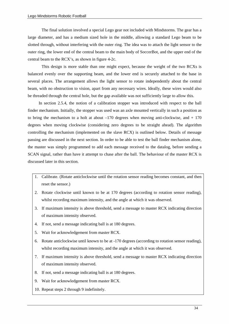
Lego Mindstorms Robotic Football
34
The final solution involved a special Lego gear not included with Mindstorms. The gear has a
large diameter, and has a medium sized hole in the middle, allowing a standard Lego beam to be
slotted through, without interfering with the outer ring. The idea was to attach the light sensor to the
outer ring, the lower end of the central beam to the main body of SoccerBot, and the upper end of the
central beam to the RCX’ s, as shown in figure 4-2c.
This design is more stable than one might expect, because the weight of the two RCXs is
balanced evenly over the supporting beam, and the lower end is securely attached to the base in
several places. The arrangement allows the light sensor to rotate independently about the central
beam, with no obstruction to vision, apart from any necessary wires. Ideally, these wires would also
be threaded through the central hole, but the gap available was not sufficiently large to allow this.
In section 2.5.4, the notion of a calibration stopper was introduced with respect to the ball
finder mechanism. Initially, the stopper was used was an axle mounted vertically in such a position as
to bring the mechanism to a holt at about –170 degrees when moving anti-clockwise, and + 170
degrees when moving clockwise (considering zero degrees to be straight ahead). The algorithm
controlling the mechanism (implemented on the slave RCX) is outlined below. Details of message
passing are discussed in the next section. In order to be able to test the ball finder mechanism alone,
the master was simply programmed to add each message received to the datalog, before sending a
SCAN signal, rather than have it attempt to chase after the ball. The behaviour of the master RCX is
discussed later in this section.
1. Calibrate. (Rotate anticlockwise until the rotation sensor reading becomes constant, and then
reset the sensor.)
2. Rotate clockwise until known to be at 170 degrees (according to rotation sensor reading),
whilst recording maximum intensity, and the angle at which it was observed.
3. If maximum intensity is above threshold, send a message to master RCX indicating direction
of maximum intensity observed.
4. If not, send a message indicating ball is at 180 degrees.
5. Wait for acknowledgement from master RCX.
6. Rotate anticlockwise until known to be at -170 degrees (according to rotation sensor reading),
whilst recording maximum intensity, and the angle at which it was observed.
7. If maximum intensity is above threshold, send a message to master RCX indicating direction
of maximum intensity observed.
8. If not, send a message indicating ball is at 180 degrees.
9. Wait for acknowledgement from master RCX.
10. Repeat steps 2 through 9 indefinitely.
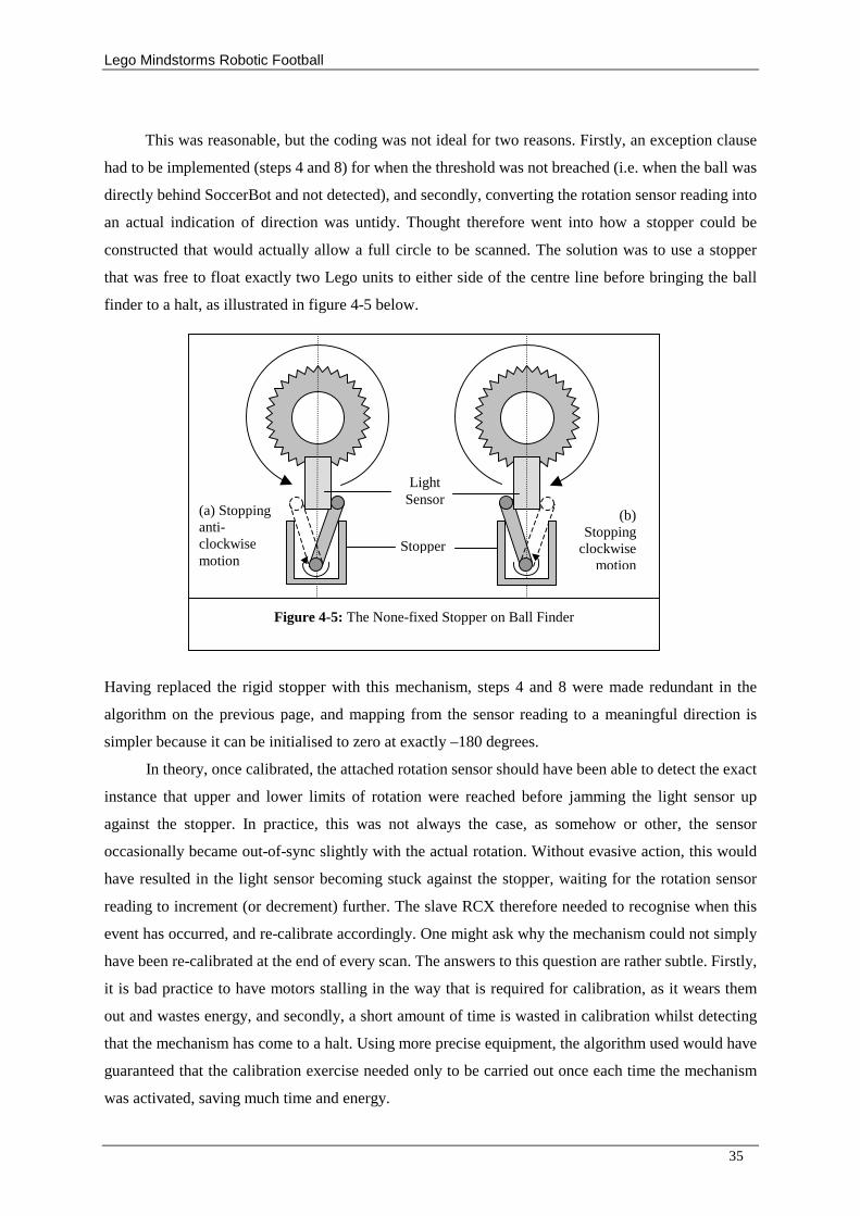
Lego Mindstorms Robotic Football
35
This was reasonable, but the coding was not ideal for two reasons. Firstly, an exception clause
had to be implemented (steps 4 and 8) for when the threshold was not breached (i.e. when the ball was
directly behind SoccerBot and not detected), and secondly, converting the rotation sensor reading into
an actual indication of direction was untidy. Thought therefore went into how a stopper could be
constructed that would actually allow a full circle to be scanned. The solution was to use a stopper
that was free to float exactly two Lego units to either side of the centre line before bringing the ball
finder to a halt, as illustrated in figure 4-5 below.
Having replaced the rigid stopper with this mechanism, steps 4 and 8 were made redundant in the
algorithm on the previous page, and mapping from the sensor reading to a meaningful direction is
simpler because it can be initialised to zero at exactly –180 degrees.
In theory, once calibrated, the attached rotation sensor should have been able to detect the exact
instance that upper and lower limits of rotation were reached before jamming the light sensor up
against the stopper. In practice, this was not always the case, as somehow or other, the sensor
occasionally became out-of-sync slightly with the actual rotation. Without evasive action, this would
have resulted in the light sensor becoming stuck against the stopper, waiting for the rotation sensor
reading to increment (or decrement) further. The slave RCX therefore needed to recognise when this
event has occurred, and re-calibrate accordingly. One might ask why the mechanism could not simply
have been re-calibrated at the end of every scan. The answers to this question are rather subtle. Firstly,
it is bad practice to have motors stalling in the way that is required for calibration, as it wears them
out and wastes energy, and secondly, a short amount of time is wasted in calibration whilst detecting
that the mechanism has come to a halt. Using more precise equipment, the algorithm used would have
guaranteed that the calibration exercise needed only to be carried out once each time the mechanism
was activated, saving much time and energy.
Stopper
Light Sensor
Figure 4-5: The None-fixed Stopper on Ball Finder
(a) Stopping anti-clockwise motion
(b) Stopping
clockwise motion
Lego Mindstorms Robotic Football
36
Once the ball finder mechanism was working correctly, the next step was to have the master
RCX react appropriately to any messages received. The initial algorithm followed was simplistic:
Repeat forever:
1. Wait for message
2. Turn off forward-backward motor (if it is on)
3. If necessary, rotate according to received message
4. Turn on forward-backward motor
The result was that SoccerBot chased the ball indefinitely. Each time a message was received that
suggested that SoccerBot was not moving approximately in the estimated direction, SoccerBot rotated
accordingly, and then continued to move forward. A touch sensor was then mounted on the front of
the robot to in such a way as to detect when possession of the ball has been gained.
4.5 RCX Communication The final protocol used was very similar to that outlined during the design stage (in section 3.8). The
final list of messages is outlined in table 4-2 below.
Sender Receiver Message Name
Message Values Description
Slave Master COLL 1 A collision has occurred.
Slave Master NCOL 2 The obstruction has been cleared.
Slave Master 100 + <direction> The direction of the ball was observed in <direction>.
Table 4-1: Finalised list of messages for RCX communication
The subtle change of using 100 as the offset for ball direction was simply to make for simpler coding.
Another change, not highlighted by comparing the two tables, is that the slave RCX converts its
rotation sensor range of 0 to 56 into SB-degrees before sending, which again makes the coding for the
master RCX cleaner, as the received message values can be put straight into the trigonometry
functions. The most significant change was the removal of the SCAN message sent from the master to
the slave. Having the slave wait for this message caused problems, due to the poor reliability of the
message passing. Instead, the master ignores any messages received recently after rotating, as these
messages would be confusing.
4.6 Using the Grey-Scale Pitch The results of the preliminary testing on the grey-scale pitch showed that the ideas presented in the
previous chapter regarding correcting dead reckoning errors were unfeasible, due to the poor accuracy
of the Mindstorms light sensors.
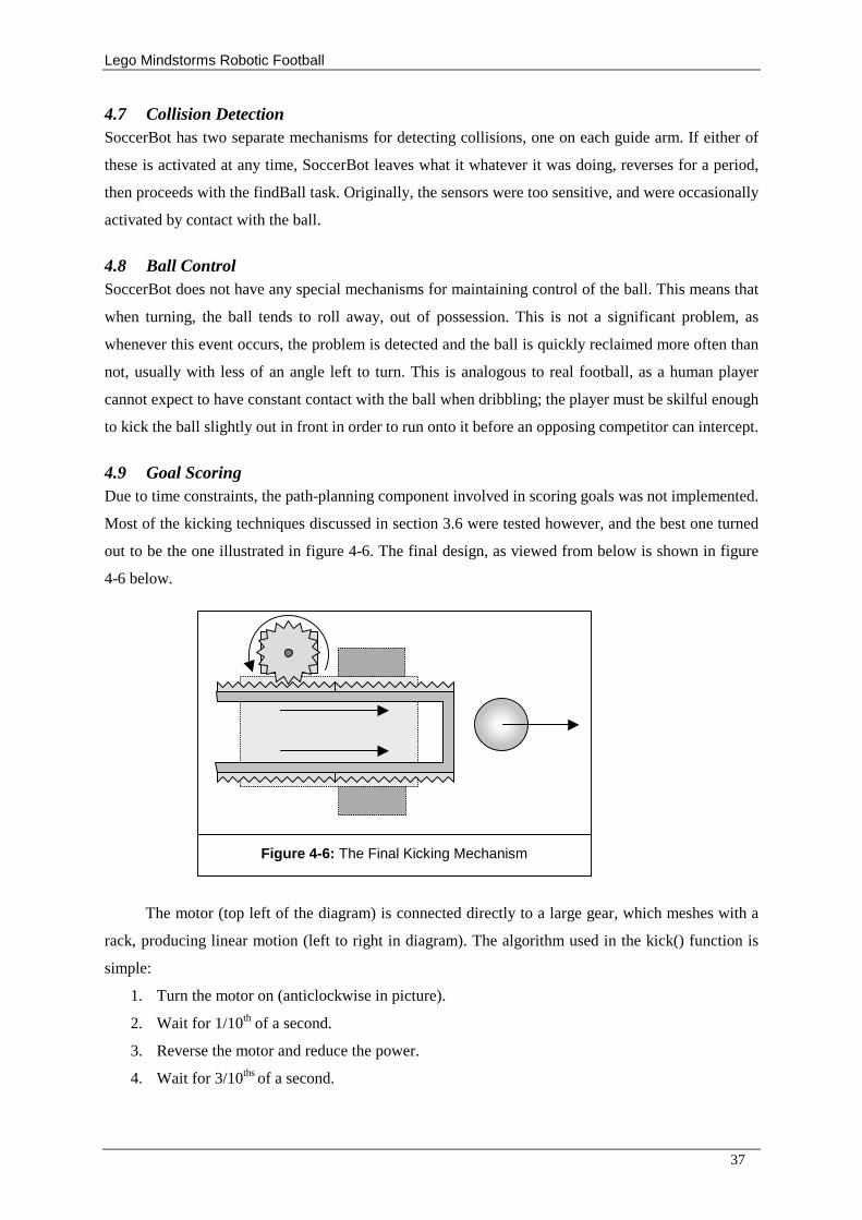
Lego Mindstorms Robotic Football
37
4.7 Collision Detection SoccerBot has two separate mechanisms for detecting collisions, one on each guide arm. If either of
these is activated at any time, SoccerBot leaves what it whatever it was doing, reverses for a period,
then proceeds with the findBall task. Originally, the sensors were too sensitive, and were occasionally
activated by contact with the ball.
4.8 Ball Control SoccerBot does not have any special mechanisms for maintaining control of the ball. This means that
when turning, the ball tends to roll away, out of possession. This is not a significant problem, as
whenever this event occurs, the problem is detected and the ball is quickly reclaimed more often than
not, usually with less of an angle left to turn. This is analogous to real football, as a human player
cannot expect to have constant contact with the ball when dribbling; the player must be skilful enough
to kick the ball slightly out in front in order to run onto it before an opposing competitor can intercept.
4.9 Goal Scoring Due to time constraints, the path-planning component involved in scoring goals was not implemented.
Most of the kicking techniques discussed in section 3.6 were tested however, and the best one turned
out to be the one illustrated in figure 4-6. The final design, as viewed from below is shown in figure
4-6 below.
The motor (top left of the diagram) is connected directly to a large gear, which meshes with a
rack, producing linear motion (left to right in diagram). The algorithm used in the kick() function is
simple:
1. Turn the motor on (anticlockwise in picture).
2. Wait for 1/10th of a second.
3. Reverse the motor and reduce the power.
4. Wait for 3/10ths of a second.
Figure 4-6: The Final Kicking Mechanism
Lego Mindstorms Robotic Football
38
After this function is called, the ball will have been propelled forward, and the mechanism will
have returned to it’ s original position. The motor’ s power has to be reduced in step three, because
otherwise the momentum of the mechanism causes it to bounce off the main body of SoccerBot when
returning to the start position, causing problems the next time a kick is performed.
4.10 Summary of Final Design SoccerBot has a dual differential drive, allowing it to drive in a straight line, either forwards, or
backwards, and rotate on the spot, either clockwise, or anticlockwise. A rotation sensor monitors the
rotation of the right wheel. On a Linoleum surface, an increase of 317 in the rotation sensor reading
relates to travelling one meter, and a reading of 136 relates to rotating 360 degrees when turning. A
technique known as dead reckoning is used to keep track of position on the pitch, and orientation.
SoccerBot detects the direction of the infrared-emitting ball using a light sensor, which can be
rotated through an angle of 360 degrees independently of the rest of the body. The slave RCX controls
the ball-finding mechanism, and keeps the master RCX up-to-date by sending messages via the
infrared communication mechanism. Having received a message, SoccerBot turns accordingly, to face
the ball, before moving forwards in that direction.
A touch sensor mounted on the front of SoccerBot is used to detect when possession of the ball
has been gained. Having gained possession, behaviour changes, in order to attempt to score a goal.
Once in position, SoccerBot kicks the ball towards goal. The kicking mechanism involves a gear
directly connected to a motor, that meshes with a rack in order to produce linear motion.
5 Final Testing
Before proceeding with the final testing and evaluation of SoccerBot, the methodologies used in the
previous projects by Goddard (2002), Fordham (2003), Varsani (2003) and Burbidge (2003) were
scrutinised. As testing and evaluation are interrelated, they are both discussed here.
Student Testing Procedure Evaluation
Goddard (2002) No formal testing procedure set out.
Brief and predominantly qualitative, criteria not justified.
Fordham (2003) A brief formal test plan. Failed to use a recognised technique.
Varsani (2003) Thorough testing, but lacking a formal plan.
Generally good, based on criteria set out by (Murphy, 2000).
Burbidge (2003) Thorough testing with quantitative results.
Failed to use a recognised technique.
The term formal plan was used to suggest a well-structured, justified test plan was devised and carried
out. Overall, there was a lack of quantities data. Most of the qualitative results presented were subject
to opinion. It was decided that the best test plan was that produced by Burbidge (2003), as this would
Lego Mindstorms Robotic Football
39
allow a detailed comparison of his robot and SoccerBot, and that Versani’ s criteria, as described by
Murphy (2000), were very appropriate, as they were specifically devised for intelligent robots.
5.1 Test Plan As far as possible, SoccerBot was tested with equivalent experiments to those conducted by Burbidge
(2003), however some were improved or adapted where it was considered necessary. All the test
results obtained are tabulated in Appendix C.
5.1.1 Ball Finding Burbidge (2003) performed a series of tests with the light sensor, in order to find a suitable threshold
to use as an indication that the sensor was facing the ball. There would have been little point in
repeating this experiment for two reasons. Firstly, the conditions in the laboratory are assumed to be
similar to last year, so his findings should still apply, and secondly, SoccerBot does not need a
threshold, as it scans a full 360-degrees, simply looking for the highest reading.
His tests on ball detection (Burbidge, 2003), and ball collection (Burbidge, 2003) provided a
better opportunity for comparison, but unfortunately, he only tested the robot’ s ability to detect the
ball for distances up to 40cm. He also used a Boolean measure (yes or no) for whether or not the robot
correctly detected the ball at each distance, and it is unclear how success was measured.
With the experiments on SoccerBot, the angle between the estimated direction of the ball, and
the actual direction was recorded for distances of up to 2 metres. Distances were measured from the
centre of SoccerBot to the centre of the ball, and to enable of an estimate of angles, SoccerBot was
placed on a large protractor. The figures shown in table C-4 are the averages from five runs of each
test. At each distance, the test was deemed a success if the estimated ball direction was, on average,
within 20 degrees of the actual ball direction. The results are evaluated in the next chapter.
Burbidge (2003) also conducted an experiment to analyse the success rate of actually making
for a stationary ball, positioned at increasing distances from his robot. Two alternative experiments
could have been conducted with SoccerBot to allow a comparison. One option would have been to
have SoccerBot commit to a particular bearing after the first scan of the ball finder, and maintain a
constant course until the ball was collected, or deemed to have been missed. The second (more
appropriate) option however, was to allow SoccerBot to proceed as it would normally, frequently
updating its estimation of ball direction, and readjusting. The reason for selecting the second option
was that it resulted in a more accurate reflection of their relative performances in a real match. To
prevent SoccerBot from persevering indefinitely to find the ball, a time limit was set. The results for
five runs of the experiment are shown in table C-5. It would have been useful if Burbidge (2003) had
also included timings in his results, for further comparison. The results are evaluated in the next
chapter.
Lego Mindstorms Robotic Football
40
5.1.2 Self-Localisation To test the accuracy of self-localisation, SoccerBot was given various sequences of instructions (such
as move forward 30cm, then rotate 90 degrees right and so on).. The first sequence was as follows:
Repeat 4 times:
1. Move forwards 159 rotation sensor clicks (50cm)
2. Rotate for 34 rotation sensor clicks (90 degrees)
These instructions, in theory, should have sent SoccerBot in a perfectly square path, so as to end up
back at the initial position and orientation. In practice of course, accuracy errors occurred, resulting in
an approximately square path being taken, meaning that SoccerBot would up some small distance
away from the actual start point. Five of these sequences were devised in total, with varying
complexity, each bringing SoccerBot back approximately to the start position. The average results for
five runs of each sequence are shown in table C-3. The average error ranged between 43mm for the
sequence described above, to 150mm for the most complex sequence. These results are evaluated in
the next section.
5.1.3 Kicking Mechanism Burbidge (2003) did not perform extensive testing on his robot’ s ability to kick the ball because it did
not have a kicking mechanism. The only data that could be found was that the primitive kicking
technique used propelled the ball about 8cm (Burbidge, 2003).
In order to test SoccerBot’ s kicking mechanism, a program was written which immediately
called the kick () function on start-up. Obviously, the ball had to be placed appropriately beforehand,
and attempts had to be made to ensure the pitch was as level as possible. The distance propelled in
each attempt was recorded, along with approximate angle between the intended direction of the kick,
and the actual direction. The results can be found in figure C-1, and again, are evaluated in the next
chapter.
6 Evaluation
6.1 Evaluation Methodology The aim of the project (as stated in section 1.1) was not necessarily to design and produce the best
possible robotic footballer; rather, it was to investigate the implications of introducing a second RCX
to a single robot. The success of the project was evaluated with this in mind. The methodology used
was that suggested by (Murphy, 2000), as used by Varsani (2003). Each of the four main criteria were
split up further where appropriate, and applied to SoccerBot, and are as follows:
Modularity: This criterion asks to what extent the solution is organised into distinct
components (or modules) Murphy (2000). Ideally, each module should be responsible for a single,
well-defined task (Deitel and Deitel, 2001, pp. 161).
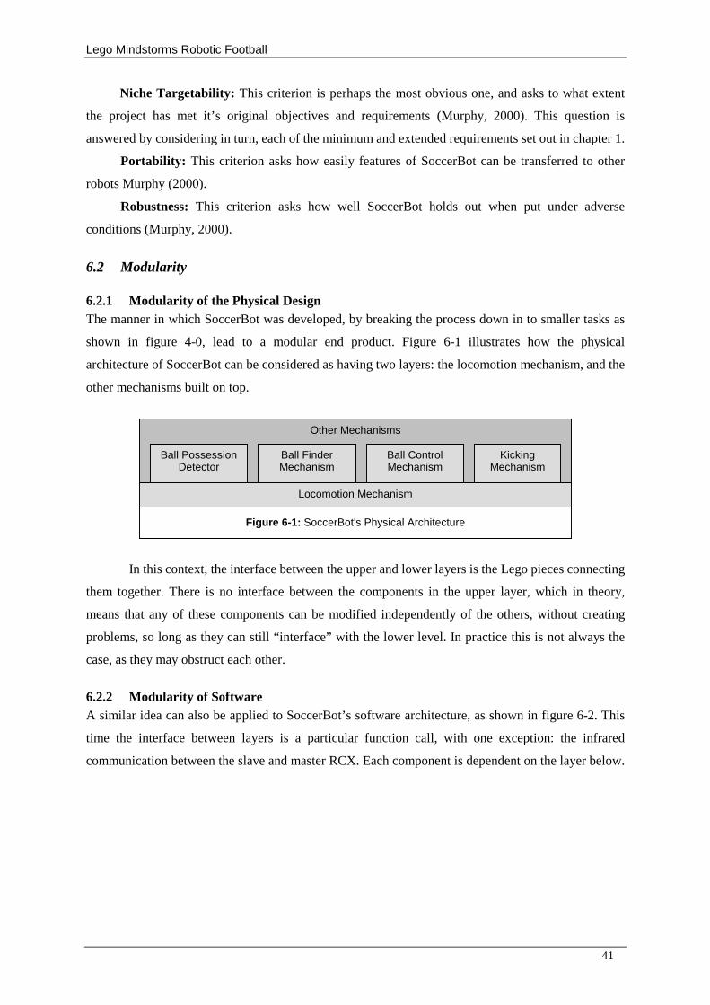
Lego Mindstorms Robotic Football
41
Niche Targetability: This criterion is perhaps the most obvious one, and asks to what extent
the project has met it’ s original objectives and requirements (Murphy, 2000). This question is
answered by considering in turn, each of the minimum and extended requirements set out in chapter 1.
Portability: This criterion asks how easily features of SoccerBot can be transferred to other
robots Murphy (2000).
Robustness: This criterion asks how well SoccerBot holds out when put under adverse
conditions (Murphy, 2000).
6.2 Modularity
6.2.1 Modularity of the Physical Design The manner in which SoccerBot was developed, by breaking the process down in to smaller tasks as
shown in figure 4-0, lead to a modular end product. Figure 6-1 illustrates how the physical
architecture of SoccerBot can be considered as having two layers: the locomotion mechanism, and the
other mechanisms built on top.
In this context, the interface between the upper and lower layers is the Lego pieces connecting
them together. There is no interface between the components in the upper layer, which in theory,
means that any of these components can be modified independently of the others, without creating
problems, so long as they can still “ interface” with the lower level. In practice this is not always the
case, as they may obstruct each other.
6.2.2 Modularity of Software A similar idea can also be applied to SoccerBot’ s software architecture, as shown in figure 6-2. This
time the interface between layers is a particular function call, with one exception: the infrared
communication between the slave and master RCX. Each component is dependent on the layer below.
Other Mechanisms
Locomotion Mechanism
Kicking Mechanism
Ball Control Mechanism
Ball Finder Mechanism
Ball Possession Detector
Figure 6-1: SoccerBot's Physical Architecture
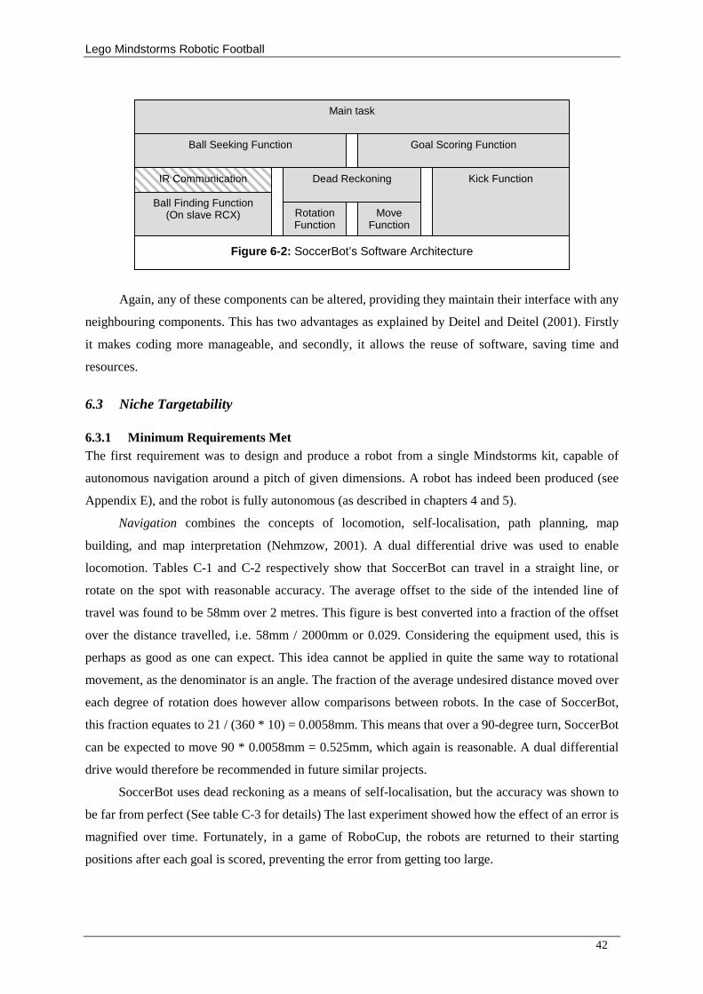
Lego Mindstorms Robotic Football
42
Again, any of these components can be altered, providing they maintain their interface with any
neighbouring components. This has two advantages as explained by Deitel and Deitel (2001). Firstly
it makes coding more manageable, and secondly, it allows the reuse of software, saving time and
resources.
6.3 Niche Targetability
6.3.1 Minimum Requirements Met The first requirement was to design and produce a robot from a single Mindstorms kit, capable of
autonomous navigation around a pitch of given dimensions. A robot has indeed been produced (see
Appendix E), and the robot is fully autonomous (as described in chapters 4 and 5).
Navigation combines the concepts of locomotion, self-localisation, path planning, map
building, and map interpretation (Nehmzow, 2001). A dual differential drive was used to enable
locomotion. Tables C-1 and C-2 respectively show that SoccerBot can travel in a straight line, or
rotate on the spot with reasonable accuracy. The average offset to the side of the intended line of
travel was found to be 58mm over 2 metres. This figure is best converted into a fraction of the offset
over the distance travelled, i.e. 58mm / 2000mm or 0.029. Considering the equipment used, this is
perhaps as good as one can expect. This idea cannot be applied in quite the same way to rotational
movement, as the denominator is an angle. The fraction of the average undesired distance moved over
each degree of rotation does however allow comparisons between robots. In the case of SoccerBot,
this fraction equates to 21 / (360 * 10) = 0.0058mm. This means that over a 90-degree turn, SoccerBot
can be expected to move 90 * 0.0058mm = 0.525mm, which again is reasonable. A dual differential
drive would therefore be recommended in future similar projects.
SoccerBot uses dead reckoning as a means of self-localisation, but the accuracy was shown to
be far from perfect (See table C-3 for details) The last experiment showed how the effect of an error is
magnified over time. Fortunately, in a game of RoboCup, the robots are returned to their starting
positions after each goal is scored, preventing the error from getting too large.
Rotation Function
Dead Reckoning
Move Function
Kick Function
Ball Seeking Function
Ball Finding Function (On slave RCX)
Goal Scoring Function
Main task
IR Communication
Figure 6-2: SoccerBot’s Software Architecture
Lego Mindstorms Robotic Football
43
Using the ball finder in conjunction with the locomotion mechanism, SoccerBot is able to
navigate towards the ball. Relating this to the given definition, the mechanism detects the direction of
the ball in relation to SoccerBot’ s current bearing, and takes the simple path required to get to it (one
rotation, and one forward movement. Secondly, having found the ball, SoccerBot’ s dead-reckoning
system gives an indication of the direction and distance to the goal from the current position.
Unfortunately, there was not enough time to fully implement the path planning required for moving to
the goal to in order to have an attempt on goal. This was considered the largest failure of the project.
The second requirement was to enhance the robot so that it is able to perform three footballing
tasks, such as locating the ball, making for the ball, dribbling with the ball, kicking the ball, and so on.
SoccerBot is in fact capable of the performing the following tasks.
1. Locate a stationary ball.
2. Move towards the ball having located it.
3. Follow a moving ball.
4. Dribble with the ball.
5. Kick the ball.
6. Detect a collision.
7. React to a collision.
SoccerBot finds the ball with its so-called ball finder, which has various advantages over the approach
used by the previous projects by Goddard (2002), Fordham (2003), Varsani (2003) and Burbidge
(2003), which was to mount a light sensor on the front of their robot, and have the entire robot spin
around searching for the ball.
In a game of RoboCup Junior football, SoccerBot will have the greatest advantage when the
ball is in motion. The reason for this is that in this situation, SoccerBot can move in the approximate
direction of the ball whilst simultaneously updating its estimation of it’ s location, whereas the other
robots will have to keep stopping to re-estimate the direction of the ball, and hence making poor
progress. In theory, when the ball is stationary, all robots, having completed their initial searches, will
travel straight towards the ball without pausing at any point, meaning that the ball finder will present
less of an advantage. SoccerBot will however have the slight benefit of knowing whether it would be
quickest to turn clockwise or anticlockwise towards the ball, whereas the other robots will turn in an
arbitrary direction.
Currently, SoccerBot heads straight towards the ball irrespective of its whereabouts. There are
of course better tactics that a robot such as SoccerBot could adopt. The main problem with the actual
technique used is that if SoccerBot has to come back down the field to collect the ball, and is facing
its own goal when possession is gained, the ball tends to be pushed towards the wrong end before
managing to reverse the direction of the ball, which can occasionally even lead to own goals being
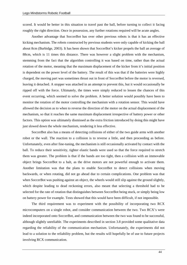
Lego Mindstorms Robotic Football
44
scored. It would be better in this situation to travel past the ball, before turning to collect it facing
roughly the right direction. Once in possession, any further rotations required will be acute angles.
Another advantage that SoccerBot has over other previous robots is that it has an effective
kicking mechanism. The robots constructed by previous students were only capable of kicking the ball
about 8cm (Burbidge, 2003). It has been shown that SoccerBot’ s kicker propels the ball an average of
88cm, which is 11 times this distance. There was however a slight problem with the mechanism,
stemming from the fact that the algorithm controlling it was based on time, rather than the actual
rotation of the motor, meaning that the maximum displacement of the kicker from it’ s initial position
is dependent on the power level of the battery. The result of this was that if the batteries were highly
charged, the moving part was sometimes thrust out in front of SoccerBot before the motor is reversed,
leaving it detached. A stopper was attached in an attempt to prevent this, but it would occasionally be
ripped off with the force. Ultimately, the times were simply reduced to lessen the chances of this
event occurring, which seemed to solve the problem. A better solution would possibly have been to
monitor the rotation of the motor controlling the mechanism with a rotation sensor. This would have
allowed the decision as to when to reverse the direction of the motor on the actual displacement of the
mechanism, so that it reaches the same maximum displacement irrespective of battery power or other
factors. This option was ultimately dismissed as the extra friction introduced by doing this might have
just slowed down the whole mechanism, rendering it less effective.
SoccerBot also has a means of detecting collisions of either of the two guide arms with another
robot or the wall. The reaction to a collision is to reverse a little, and then proceeding as before.
Unfortunately, even after fine-tuning, the mechanism is still occasionally activated by contact with the
ball. To reduce their sensitivity, tighter elastic bands were used so that the force required to stretch
them was greater. The problem is that if the bands are too tight, then a collision with an immovable
object brings SoccerBot to a halt, as the drive motors are not powerful enough to activate them.
Another limitation was that the plans to enable SoccerBot to detect collisions when moving
backwards, or when rotating, did not go ahead due to certain complications. One problem was that
when SoccerBot was pushing against an object, the wheels would still slip against the ground slightly,
which despite leading to dead reckoning errors, also meant that selecting a threshold had to be
selected for the rate of rotation that distinguishes between SoccerBot being stuck, or simply being low
on battery power for example. Tests showed that this would have been difficult, if not impossible.
The third requirement was to experiment with the possibility of incorporating two RCX
microcomputers on a single robot, and consider communication between the two. Two RCX’ s were
indeed incorporated onto SoccerBot, and communication between the two was found to be successful,
although slightly unreliable. The experiments described in section 3.8 provided some qualitative data
regarding the reliability of the communication mechanism. Unfortunately, the experiments did not
lead to a solution to the reliability problem, but the results will hopefully be of use to future projects
involving RCX communication.
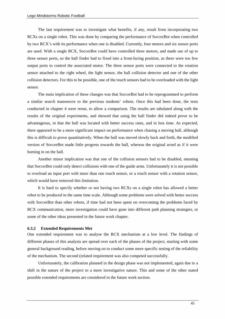
Lego Mindstorms Robotic Football
45
The last requirement was to investigate what benefits, if any, result from incorporating two
RCXs on a single robot. This was done by comparing the performance of SoccerBot when controlled
by two RCX’ s with its performance when one is disabled. Currently, four motors and six sensor ports
are used. With a single RCX, SoccerBot could have controlled three motors, and made use of up to
three sensor ports, so the ball finder had to fixed into a front-facing position, as there were too few
output ports to control the associated motor. The three sensor ports were connected to the rotation
sensor attached to the right wheel, the light sensor, the ball collision detector and one of the other
collision detectors. For this to be possible, one of the touch sensors had to be overloaded with the light
sensor.
The main implication of these changes was that SoccerBot had to be reprogrammed to perform
a similar search manoeuvre to the previous students’ robots. Once this had been done, the tests
conducted in chapter 4 were rerun, to allow a comparison. The results are tabulated along with the
results of the original experiments, and showed that using the ball finder did indeed prove to be
advantageous, in that the ball was located with better success rates, and in less time. As expected,
there appeared to be a more significant impact on performance when chasing a moving ball, although
this is difficult to prove quantitatively. When the ball was moved slowly back and forth, the modified
version of SoccerBot made little progress towards the ball, whereas the original acted as if it were
homing in on the ball.
Another minor implication was that one of the collision sensors had to be disabled, meaning
that SoccerBot could only detect collisions with one of the guide arms. Unfortunately it is not possible
to overload an input port with more than one touch sensor, or a touch sensor with a rotation sensor,
which would have removed this limitation.
It is hard to specify whether or not having two RCXs on a single robot has allowed a better
robot to be produced in the same time scale. Although some problems were solved with better success
with SoccerBot than other robots, if time had not been spent on overcoming the problems faced by
RCX communication, more investigation could have gone into different path planning strategies, or
some of the other ideas presented in the future work chapter.
6.3.2 Extended Requirements Met One extended requirement was to analyse the RCX mechanism at a low level. The findings of
different phases of this analysis are spread over each of the phases of the project, starting with some
general background reading, before moving on to conduct some more specific testing of the reliability
of the mechanism. The second (related requirement was also competed successfully.
Unfortunately, the calibration planned in the design phase was not implemented, again due to a
shift in the nature of the project to a more investigative nature. This and some of the other stated
possible extended requirements are considered in the future work section.
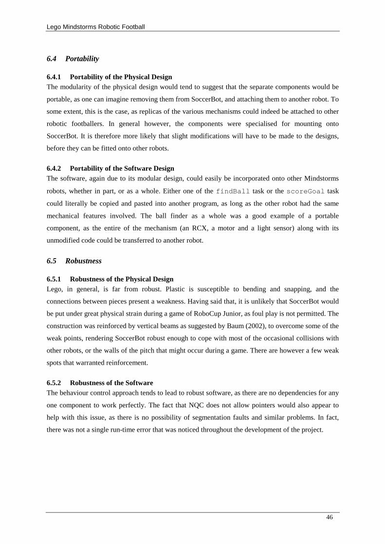
Lego Mindstorms Robotic Football
46
6.4 Portability
6.4.1 Portability of the Physical Design The modularity of the physical design would tend to suggest that the separate components would be
portable, as one can imagine removing them from SoccerBot, and attaching them to another robot. To
some extent, this is the case, as replicas of the various mechanisms could indeed be attached to other
robotic footballers. In general however, the components were specialised for mounting onto
SoccerBot. It is therefore more likely that slight modifications will have to be made to the designs,
before they can be fitted onto other robots.
6.4.2 Portability of the Software Design The software, again due to its modular design, could easily be incorporated onto other Mindstorms
robots, whether in part, or as a whole. Either one of the findBall task or the scoreGoal task
could literally be copied and pasted into another program, as long as the other robot had the same
mechanical features involved. The ball finder as a whole was a good example of a portable
component, as the entire of the mechanism (an RCX, a motor and a light sensor) along with its
unmodified code could be transferred to another robot.
6.5 Robustness
6.5.1 Robustness of the Physical Design Lego, in general, is far from robust. Plastic is susceptible to bending and snapping, and the
connections between pieces present a weakness. Having said that, it is unlikely that SoccerBot would
be put under great physical strain during a game of RoboCup Junior, as foul play is not permitted. The
construction was reinforced by vertical beams as suggested by Baum (2002), to overcome some of the
weak points, rendering SoccerBot robust enough to cope with most of the occasional collisions with
other robots, or the walls of the pitch that might occur during a game. There are however a few weak
spots that warranted reinforcement.
6.5.2 Robustness of the Software The behaviour control approach tends to lead to robust software, as there are no dependencies for any
one component to work perfectly. The fact that NQC does not allow pointers would also appear to
help with this issue, as there is no possibility of segmentation faults and similar problems. In fact,
there was not a single run-time error that was noticed throughout the development of the project.
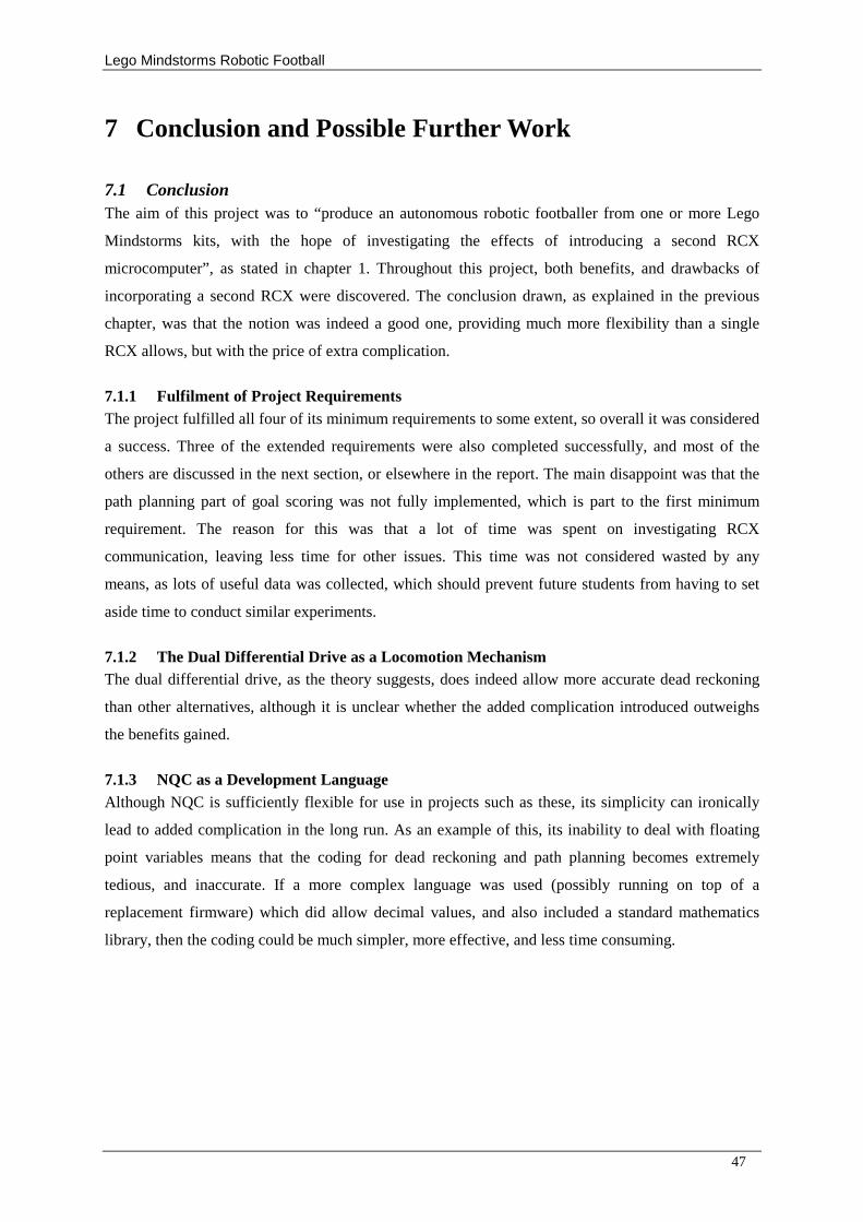
Lego Mindstorms Robotic Football
47
7 Conclusion and Possible Further Work
7.1 Conclusion The aim of this project was to “ produce an autonomous robotic footballer from one or more Lego
Mindstorms kits, with the hope of investigating the effects of introducing a second RCX
microcomputer” , as stated in chapter 1. Throughout this project, both benefits, and drawbacks of
incorporating a second RCX were discovered. The conclusion drawn, as explained in the previous
chapter, was that the notion was indeed a good one, providing much more flexibility than a single
RCX allows, but with the price of extra complication.
7.1.1 Fulfilment of Project Requirements The project fulfilled all four of its minimum requirements to some extent, so overall it was considered
a success. Three of the extended requirements were also completed successfully, and most of the
others are discussed in the next section, or elsewhere in the report. The main disappoint was that the
path planning part of goal scoring was not fully implemented, which is part to the first minimum
requirement. The reason for this was that a lot of time was spent on investigating RCX
communication, leaving less time for other issues. This time was not considered wasted by any
means, as lots of useful data was collected, which should prevent future students from having to set
aside time to conduct similar experiments.
7.1.2 The Dual Differential Drive as a Locomotion Mechanism The dual differential drive, as the theory suggests, does indeed allow more accurate dead reckoning
than other alternatives, although it is unclear whether the added complication introduced outweighs
the benefits gained.
7.1.3 NQC as a Development Language Although NQC is sufficiently flexible for use in projects such as these, its simplicity can ironically
lead to added complication in the long run. As an example of this, its inability to deal with floating
point variables means that the coding for dead reckoning and path planning becomes extremely
tedious, and inaccurate. If a more complex language was used (possibly running on top of a
replacement firmware) which did allow decimal values, and also included a standard mathematics
library, then the coding could be much simpler, more effective, and less time consuming.
Lego Mindstorms Robotic Football
48
7.2 Further Work
7.2.1 Calibration Due to time constraints, a calibration function, as suggested in
7.2.2 Goal Scoring As mentioned previously, SoccerBot is unable to calculate the direction of the goal correctly, in order
to be able to score a goal. An obvious enhancement to the robot would therefore be to implement this
capability. It would be interesting to consider various path-planning algorithms for making for the
goal, rather than just taking a direct route as was attempted in this project. One effective, and possibly
quite simple approach might be to head straight for the centre line, before turning towards the goal,
and shooting. The idea behind this is that shooting from the centre of the goal allows a greater margin
for error than at tight angles.
7.2.3 Alternative Tactics SoccerBot’ s tactics at present are extremely aggressive; staying back to defend is never considered an
option. It might have been interesting to consider how a defensive robotic footballer, or even a
goalkeeper might be programmed, and how the physical design might be changed. One idea for a
goalkeeper might be to mount the wheels at 90 degrees to the rest of the robot, in order to be able to
move across the goalmouth quickly, whilst still facing towards the attacking player.
7.2.4 Teamwork and Message Passing Between robots The key to winning a real football match is teamwork. If several reincarnations of SoccerBot were to
play on the same team, there would be chaos, as each robot raced after the ball. The likelihood would
be that each would get in the way of the others, possibly resulting in a poorer overall performance
than a single robot would achieve. One way to organise the team would be to have each robot adopt a
different role, as discussed under the previous heading.
Another important aspect of teamwork however is communication. One of the problems with
communication between Mindstorms footballers is that for messages to be sent between RCXs, they
have to be pointed roughly towards each other, which will not always be the case in dynamic, partially
observable environments such as football. The reason communication is not possible in these
circumstances is that infrared light cannot travel through solid objects. It would be useful if somehow
a radio wave transmitter and receiver could be attached to one of the RCX output ports and an inputs
ports respectively. Varsani (2003) suggests a technology such as Bluetooth, which would allow
messages to be sent irrespective of the orientations of two communicating RCXs.
Assuming that this is possible, there are still various complications to be considered. Firstly,
each RCX needs to be able to distinguish whether or not a particular message was intended for them,
as messages are broadcast to all robots. A simple way would be to reserve a range of message for each
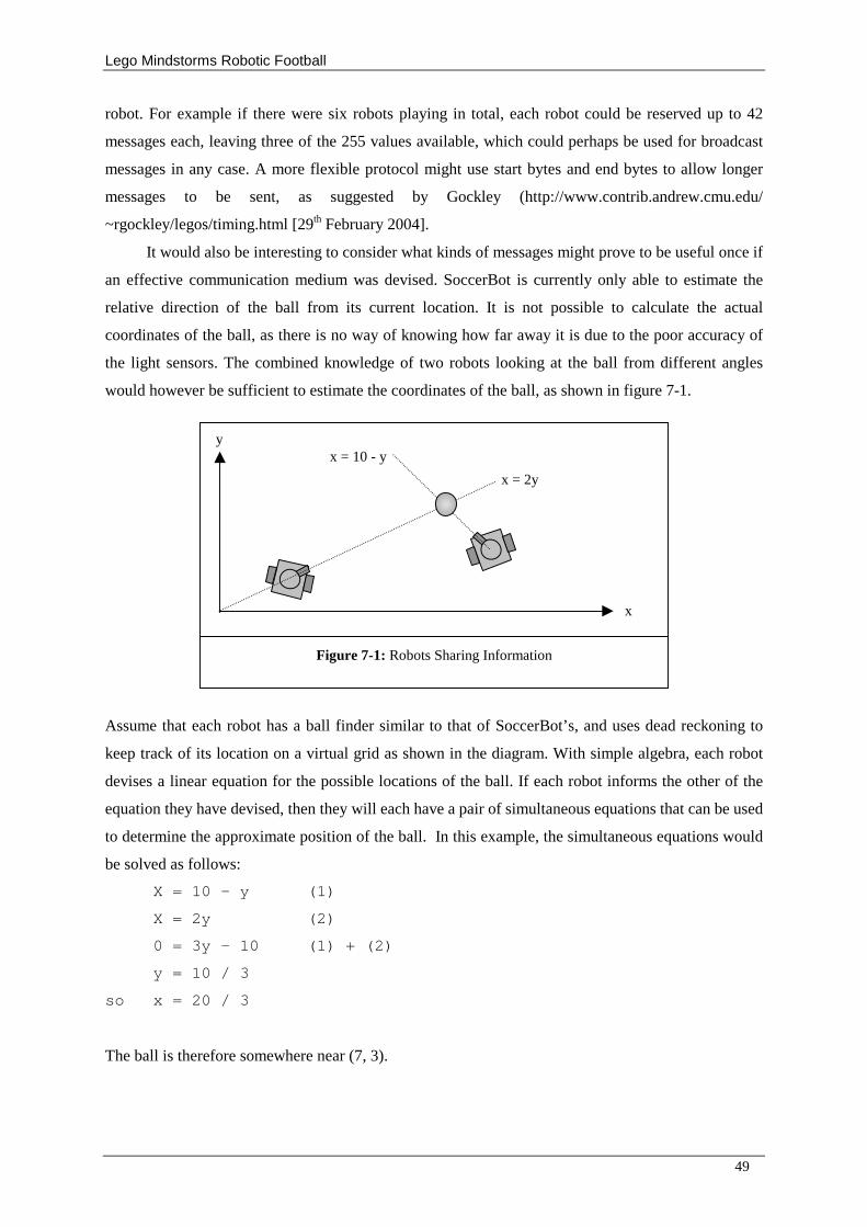
Lego Mindstorms Robotic Football
49
robot. For example if there were six robots playing in total, each robot could be reserved up to 42
messages each, leaving three of the 255 values available, which could perhaps be used for broadcast
messages in any case. A more flexible protocol might use start bytes and end bytes to allow longer
messages to be sent, as suggested by Gockley (http://www.contrib.andrew.cmu.edu/
~rgockley/legos/timing.html [29th February 2004].
It would also be interesting to consider what kinds of messages might prove to be useful once if
an effective communication medium was devised. SoccerBot is currently only able to estimate the
relative direction of the ball from its current location. It is not possible to calculate the actual
coordinates of the ball, as there is no way of knowing how far away it is due to the poor accuracy of
the light sensors. The combined knowledge of two robots looking at the ball from different angles
would however be sufficient to estimate the coordinates of the ball, as shown in figure 7-1.
Assume that each robot has a ball finder similar to that of SoccerBot’ s, and uses dead reckoning to
keep track of its location on a virtual grid as shown in the diagram. With simple algebra, each robot
devises a linear equation for the possible locations of the ball. If each robot informs the other of the
equation they have devised, then they will each have a pair of simultaneous equations that can be used
to determine the approximate position of the ball. In this example, the simultaneous equations would
be solved as follows:
X = 10 – y (1)
X = 2y (2)
0 = 3y – 10 (1) + (2)
y = 10 / 3
so x = 20 / 3
The ball is therefore somewhere near (7, 3).
x
y
x = 2y
x = 10 - y
Figure 7-1: Robots Sharing Information
Lego Mindstorms Robotic Football
50
7.2.5 Alternative Projects Now that robotic football has been attempted by various students,
7.2.6 Message Passing Between Robots and a PC Varsani (2003) referred to the idea of message passing between RCX and PC as “ Distributing the
Workload” , as this it allows the PC to do some of the work that would otherwise have to be done on
the RCX itself. In theory, the idea is a good one, as it would allow some of the limitations of the RCX
to be overcome. Having investigated the communication mechanism, it is unclear as to whether the
benefits of doing this would outweigh the extra complexity introduced by the sending and receiving of
messages.
7.2.7 Genetic Algorithms Rather than telling a robot how to play football by providing it with simple rules, it would be more
exciting to allow a agent to learn for itself. Genetic algorithms provide a way of doing this
7.2.8 Alternative Programming Languages One conclusion drawn from this project was that NQC is perhaps not the most suitable development
language for projects of this scope. It would be interesting to see what can be achieved in a similar
time scale using replacement firmware, Even if the conclusion turns out to be that the alternatives are
in fact less relevant than NQC, it would have been time well spent as future students would be aware
of the problems presented.
Lego Mindstorms Robotic Football
51
References
Baum, D., (2002), A Definitive Guide to Lego Mindstorms, Second Edition, Knox, A. (editor), ch. 10 and pp. 18, 73, 79, 22, 105 – 166, 176 and 233, Apress, Berkely, CA. Baum, D., Gasperi, M., Hempel, R., Villa, L., (2001), Extreme Mindstorms: An Advanced Guide to LEGO MINDSTORMS, Burke, K. (editor), pp. 11 – 29, Apress, Berkely, CA. Bennett, S, McRobb, S and Farmer, R., (2002), Object Oriented Systems Analysis and Design Using UML - Second Edition, Graham, C. and Douglas, S. (editors), pp. 48 – 53, McGraw-Hill Education, Maidenhead, Berkshire. Burbidge, David, (2003), Robotic Football - Final Year Project, School of Computing, University of Leeds, ch. 4, pp. 36, 41, 46.and 54. Dartmouth College Computer Science Department Robot Building Course, Robo-Rats Locomotion: Dual Differential Drive, URL: http://www.cs.dartmouth.edu/~robotlab/robotlab/courses/cs542001s/dualdiff.html [22nd November 2003] Deitel and Deitel, (2001), C++ - How to Program, Third Edition, Horton, M., Recter, PJ., Burrows, S., Schlutz, K., Trentacoste, C., George, DA., O’ Brien, V. (editors), pp. 161, Prentice-Hall, Inc., Upper Saddle River, NJ. Dorst, Leo, Translational joint / Electric piston, URL: http://carol.wins.uva.nl/~leo/lego/piston.html [29th November 2003] Fordham, Anthony, (2003), Lego Mindstorms Robotic Football - Final Year Project, School of Computing, University of Leeds, ch. 4, and pp. 48. Gockley, Rachel, Infrared Communication, URL: http://www.contrib.andrew.cmu.edu/~rgockley/legos/ir.html [29th February 2004] Gockley, Rachel, Message Timing, URL: http://www.contrib.andrew.cmu.edu/~rgockley/legos/timing.html [29th February 2004] Gockley, Rachel, Multi-Robot Communication with LEGO Mindstorms, URL: http://www.contrib.andrew.cmu.edu/~rgockley/legos/index.html [29th February 2004] Goddard, Matthew (2002), Lego Mindstorms Robotic Football – Final Year Project, School of Computing, University Of Leeds. Jones, J., Seiger, B., Flynn, A., (1998), Mobile Robotics – Inspiration to Implementation, Second Edition, pp. 174 – 289, A K Peters Ltd., Natick, MA. Kevan, Paul., (2003), A Lego Mindstorms Maze Finding Robot, School of Computing, University of Leeds Murphy, Robin R., (2000), Introduction to AI Robotics, MIT Press, Cumberland, RI.
Lego Mindstorms Robotic Football
52
Nehmzow, U., (2001), Mobile Robotics: Research, Applications and Challenges, Department of
Computer Studies, University of Manchester.
Proudfoot, K., (1998), Reverse Engineering the RCX, Stanford University, URL: http://graphics.stanford.edu/~kekoa/rcx/talk/talk.005.html [5th February 2004] RoboCup, Sony CSL, RoboCup: The Robot World Cup, URL: http://www.csl.sony.co.jp/person/kitano/RoboCup/RoboCup-old.html [20th November 2003] RoboCup Junior (Australia), RoboCup Junior Australia, URL: http://www.robocupjunior.org.au [5th April 2004] Russell, S. and Norvig, P. (2003), Artificial Intelligence – A Modern Approach, Second Edition, Horton, M., J., Holm, TD., Lindner, P., O’ Brien, V, Trentacoste, C., Zucker, I. (editors), Pearson Education Inc., Upper Saddle River, NJ. Sumpter, N., (2000), The Robotic Sheepdog, Thesis (Ph.D.) School of Computing, University of Leeds The Cognitive Robotics Group, University of Toronto (2002), Golog, URL: http://www.cs.toronto.edu/cogrobo/ [5th February 2004] Techno-stuff, Sensors, URL: http://www.techno-stuff.com/sensors.htm [2nd April 2004] Varsani, J., (2003), Robotic Football - Final Year Project, School of Computing, University of Leeds, ch. 4., ch. 7 and pp. 29.
Lego Mindstorms Robotic Football
53
Appendix A – Personal Reflection
7.3 Aspects of the project that went particularly well I am most proud of the actual physical design of SoccerBot. The dual differential drive is compact,
accurate, and efficient, and the ball finding and kicking mechanisms are very effective too. Of these
features, the latter is my particular favourite, as all the previous University of Leeds students
undertaking Mindstorms-based projects have failed to boast a comparable mechanism. Ironically,
most of the non-productive hours that were spent on the project were due to physical problems. With
regard to programming, the ball finding task (findBall()) was impressive for it’ s shear simplicity. The
NCQ code maps almost exactly to the description presented in the design chapter. Finally, the
experimentation with RCX message passing also lead to some interesting findings, which may prove
useful to other students in future
7.4 Aspects of the project that did not go particularly well The coding for dead reckoning was very problematic. The reason for this is that debugging was
particularly difficult, as it unclear from SoccerBot’ s behaviour as to what is going on with the code.
Usually when developing software on a standard PC, printing to the screen can be a useful way of
highlighting problems. As the LCD screen of an RCX is only capable of displaying a few characters,
this approach is not feasible when programming Mindstorms robots. The implication of this was that
there wasn’ t sufficient time to explore the path planning techniques required for scoring goals.
7.5 Advice to Students Considering Undertaking a Similar Project For any students looking for a diverse and open-ended project, one based on Lego Mindstorms should
definitely be considered a possibility. Experience with Lego Technics would be desirable, but I do
consider this to be of utmost importance, as there is sufficient time to practice with the Mindstorms kit
before committing to a final design. Patience is definitely an essential trait, as the Mindstorms
equipment is far from reliable at the best of times, and what may appear to be a perfectly feasible
design, may turn out to be unpractical simply due to the poor quality of the equipment.
This type of projects is better suited to those willing to experiment and try ideas out, rather than
those who prefer to set out exactly what is to be done up-front, before proceeding with
implementation. A certain degree of creativity is also required in order to overcome the wide variety
of problems that present themselves throughout the course of the project.
7.6 Advice for Future Students Undertaking Similar Projects In agreement with Fordham (2003), Versani (2003), and Burbidge (2003), I would advise not to
underestimate the time that needs to be allocated to the physical design and construction of the robot.
Each of these previous students (and indeed myself), allowed a set number of weeks for this task, after
Lego Mindstorms Robotic Football
54
which it was expected that one could concentrate purely on programming and testing. This was untrue
in every case. It is more reasonable to anticipate that modifications to the physical design will be
necessary throughout the entire duration of the project. One of the reasons for this is that any false
assumptions made in the construction phase are often not found to be inaccurate until coding and
testing is underway. As an example from this project, it was initially assumed that the infrared
communication between the RCX’ s would be reliable, which later turned out not to be the case.
A second lesson learned, was that however much one perseveres with Mindstorms robots, a
perfect design will not be found. One would be naïve to think otherwise, as was I when I began the
project. The main reason for this is that the equipment in the Mindstorms kits is not particularly
accurate. As an example, it would have been useful to be able to monitor the grey-scale pitch with
light sensors, but this turned out to be unreliable. Failure to take this fact into account will result in
time being wasted on attempting to perfect a single aspect of a robot. Time is better spent by
experimenting with as many different features as possible, which together, will lead to a more
impressive robot. The theory behind this is that if these features complement each other, then there
can be some redundancy, allowing slight imperfections. Crudely put, they will “ cover for each other” .
Relying on one aspect being perfect is dangerous, and impractical when using the Mindstorms kits.
7.7 Advice for Future Students in General A more generic lesson learned was that it is important to make the most of having a supervisor. As a
third year university student, you cannot expect your supervisor to be pressing you to get the required
work done; rather, you must ask them for advice on what should be done next, asking for feedback
and so on. I found that having a weekly meeting with my supervisor proved useful. I made sure that
before terminating the meeting, I knew the answers the following key questions:
1. What does the supervisor think of the work I have done since the last meeting?
2. Have I done the work that I should have since the last meeting?
3. What do I need to have done by the next meeting?
The first question is extremely important, as your supervisor is partly responsible for marking
your report. Tailoring your project according to any comments made is an easy way of gaining extra
credit. In a sense, it doesn’ t really matter where you think your project should be heading; you instead
need to think about pleasing your supervisor. In fact, he or she should be considered your “ end user” .
Considering the second of these questions helps to prevent falling too far behind schedule. If
the answer is “ no” , then extra work will need to be put in the next week. Similarly, the answer to the
third question ensures that one has a target to aim for the next week.
The mid-term report is also a great opportunity for obtaining detailed feedback from your
assessor as well as your supervisor. Unfortunately, I was engaged in other coursework at the time the
Lego Mindstorms Robotic Football
55
deadline, resulting in a poor report being handed in, but nevertheless all the comments were taken into
account.
My final piece of advice would be to choose minimum requirements carefully, so as not to
commit to solving a particular problem. Think of open-ended investigative objectives, which allow
more scope for discussion and evaluation, and don’ t be afraid to request a change in the requirements
at any stage.
7.8 Evaluation of Project Schedule The initial schedule ignored the fact that the workload was greater in the first semester than in the
second with respect to other modules, and the fact that December 2003 and January 2004 would be
devoted to revision for examinations. The result was over ambitious targets for the early stages. The
Christmas break was a useful time to get the project back on track, but deliverable deadlines for early
this year (2004), proposed in the initial schedule were still unfeasible. I think that these deadlines
would have been hard to meet even with an even split of final year modules.
An uneven split of modules is recommended (with 5 in the first semester and 3 in the second),
as this has psychological benefits as well as making it easier to catch up should one find them self
behind schedule. University holidays are also a good opportunity to put in a lot of work. It was found
that with good organisation, it was possible to work in the morning and afternoon during weekdays,
leaving evenings and weekends free.
Writing up the report alongside implementation also appears to have been a good idea for two
reasons. Firstly, it guaranteed that no matter how well the project went, it was never going to be the
case that credit deserved for any practical work would not be awarded due to not having enough time
to write about it. Secondly, writing up work done when it is fresh in ones mind means that it is less
likely that any problems that had to be resolved and so on will be forgotten.
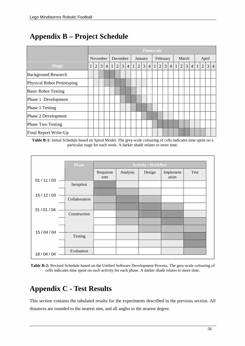
Lego Mindstorms Robotic Football
56
Appendix B – Project Schedule
Timescale
November December January February March April
Stage 1 2 3 4 1 2 3 4 1 2 3 4 1 2 3 4 1 2 3 4 1 2 3 4
Background Research
Physical Robot Prototyping
Basic Robot Testing
Phase 1 Development
Phase 1 Testing
Phase 2 Development
Phase Two Testing
Final Report Write-Up
Table B-1: Initial Schedule based on Spiral Model. The grey-scale colouring of cells indicates time spent on a particular stage for each week. A darker shade relates to more time.
Activity / Workflow
Phase
Requirements
Analysis Design Implementation
Test
Inception
Collaboration
Construction
Testing
Evaluation
Table B-2: Revised Schedule based on the Unified Software Development Process. The grey-scale colouring of cells indicates time spent on each activity for each phase. A darker shade relates to more time.
Appendix C - Test Results
This section contains the tabulated results for the experiments described in the previous section. All
distances are rounded to the nearest mm, and all angles to the nearest degree.
01 / 11 / 03
15 / 12 / 03
31 / 01 / 04
15 / 04 / 04
18 / 04 / 04
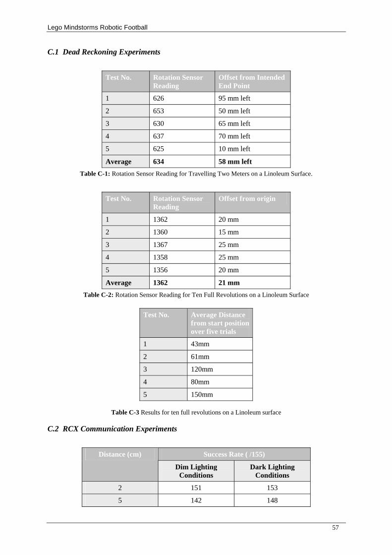
Lego Mindstorms Robotic Football
57
C.1 Dead Reckoning Experiments
Test No. Rotation Sensor Reading
Offset from Intended End Point
1 626 95 mm left
2 653 50 mm left
3 630 65 mm left
4 637 70 mm left
5 625 10 mm left
Average 634 58 mm left
Table C-1: Rotation Sensor Reading for Travelling Two Meters on a Linoleum Surface.
Test No. Rotation Sensor Reading
Offset from origin
1 1362 20 mm
2 1360 15 mm
3 1367 25 mm
4 1358 25 mm
5 1356 20 mm
Average 1362 21 mm
Table C-2: Rotation Sensor Reading for Ten Full Revolutions on a Linoleum Surface
Test No. Average Distance from start position over five trials
1 43mm
2 61mm
3 120mm
4 80mm
5 150mm
Table C-3 Results for ten full revolutions on a Linoleum surface
C.2 RCX Communication Experiments
Success Rate ( /155) Distance (cm)
Dim Lighting Conditions
Dark Lighting Conditions
2 151 153
5 142 148
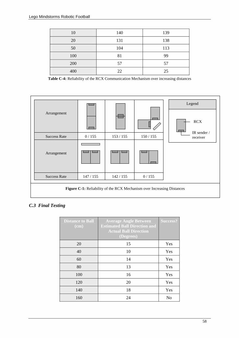
Lego Mindstorms Robotic Football
58
10 140 139
20 131 138
50 104 113
100 81 99
200 57 57
400 22 25
Table C-4: Reliability of the RCX Communication Mechanism over increasing distances
C.3 Final Testing
Distance to Ball (cm)
Average Angle Between Estimated Ball Direction and
Actual Ball Direction (Degrees)
Success?
20 15 Yes
40 10 Yes
60 14 Yes
80 13 Yes
100 16 Yes
120 20 Yes
140 18 Yes
160 24 No
0 / 155 153 / 155 150 / 155
147 / 155 142 / 155 0 / 155
Success Rate
Success Rate
Arrangement
Arrangement
Legend
RCX
IR sender / receiver
Figure C-1: Reliability of the RCX Mechanism over Increasing Distances
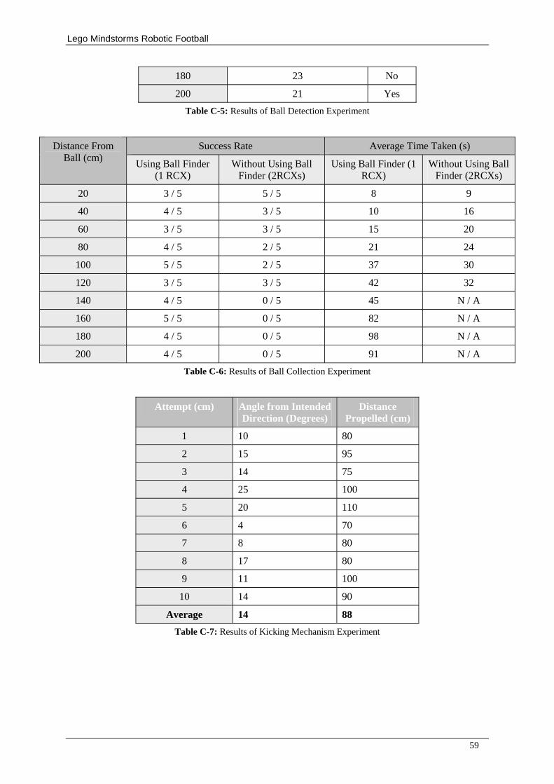
Lego Mindstorms Robotic Football
59
180 23 No
200 21 Yes
Table C-5: Results of Ball Detection Experiment
Success Rate Average Time Taken (s) Distance From Ball (cm)
Using Ball Finder (1 RCX)
Without Using Ball Finder (2RCXs)
Using Ball Finder (1 RCX)
Without Using Ball Finder (2RCXs)
20 3 / 5 5 / 5 8 9
40 4 / 5 3 / 5 10 16
60 3 / 5 3 / 5 15 20
80 4 / 5 2 / 5 21 24
100 5 / 5 2 / 5 37 30
120 3 / 5 3 / 5 42 32
140 4 / 5 0 / 5 45 N / A
160 5 / 5 0 / 5 82 N / A
180 4 / 5 0 / 5 98 N / A
200 4 / 5 0 / 5 91 N / A
Table C-6: Results of Ball Collection Experiment
Attempt (cm) Angle from Intended Direction (Degrees)
Distance Propelled (cm)
1 10 80
2 15 95
3 14 75
4 25 100
5 20 110
6 4 70
7 8 80
8 17 80
9 11 100
10 14 90
Average 14 88
Table C-7: Results of Kicking Mechanism Experiment
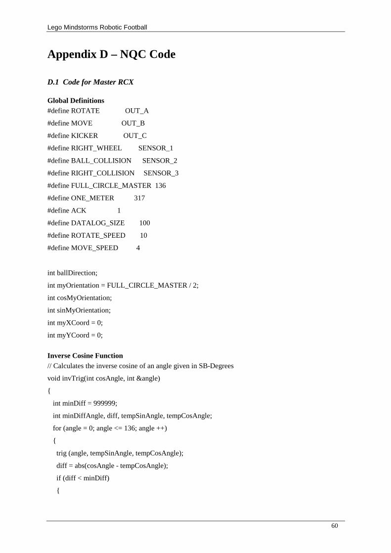
Lego Mindstorms Robotic Football
60
Appendix D – NQC Code
D.1 Code for Master RCX
Global Definitions #define ROTATE OUT_A
#define MOVE OUT_B
#define KICKER OUT_C
#define RIGHT_WHEEL SENSOR_1
#define BALL_COLLISION SENSOR_2
#define RIGHT_COLLISION SENSOR_3
#define FULL_CIRCLE_MASTER 136
#define ONE_METER 317
#define ACK 1
#define DATALOG_SIZE 100
#define ROTATE_SPEED 10
#define MOVE_SPEED 4
int ballDirection;
int myOrientation = FULL_CIRCLE_MASTER / 2;
int cosMyOrientation;
int sinMyOrientation;
int myXCoord = 0;
int myYCoord = 0;
Inverse Cosine Function // Calculates the inverse cosine of an angle given in SB-Degrees
void invTrig(int cosAngle, int &angle)
{
int minDiff = 999999;
int minDiffAngle, diff, tempSinAngle, tempCosAngle;
for (angle = 0; angle <= 136; angle ++)
{
trig (angle, tempSinAngle, tempCosAngle);
diff = abs(cosAngle - tempCosAngle);
if (diff < minDiff)
{
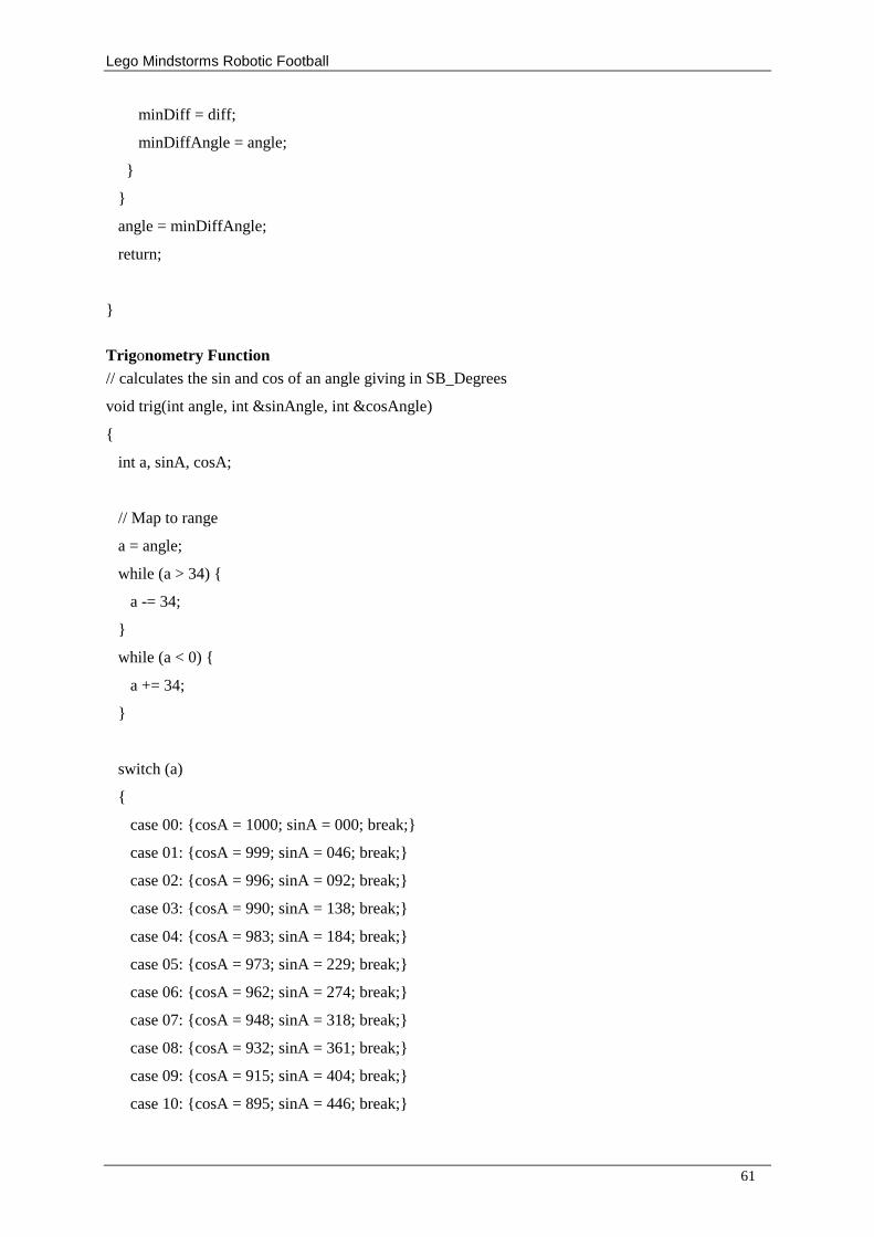
Lego Mindstorms Robotic Football
61
minDiff = diff;
minDiffAngle = angle;
}
}
angle = minDiffAngle;
return;
}
Trigonometry Function // calculates the sin and cos of an angle giving in SB_Degrees
void trig(int angle, int &sinAngle, int &cosAngle)
{
int a, sinA, cosA;
// Map to range
a = angle;
while (a > 34) {
a -= 34;
}
while (a < 0) {
a += 34;
}
switch (a)
{
case 00: {cosA = 1000; sinA = 000; break;}
case 01: {cosA = 999; sinA = 046; break;}
case 02: {cosA = 996; sinA = 092; break;}
case 03: {cosA = 990; sinA = 138; break;}
case 04: {cosA = 983; sinA = 184; break;}
case 05: {cosA = 973; sinA = 229; break;}
case 06: {cosA = 962; sinA = 274; break;}
case 07: {cosA = 948; sinA = 318; break;}
case 08: {cosA = 932; sinA = 361; break;}
case 09: {cosA = 915; sinA = 404; break;}
case 10: {cosA = 895; sinA = 446; break;}
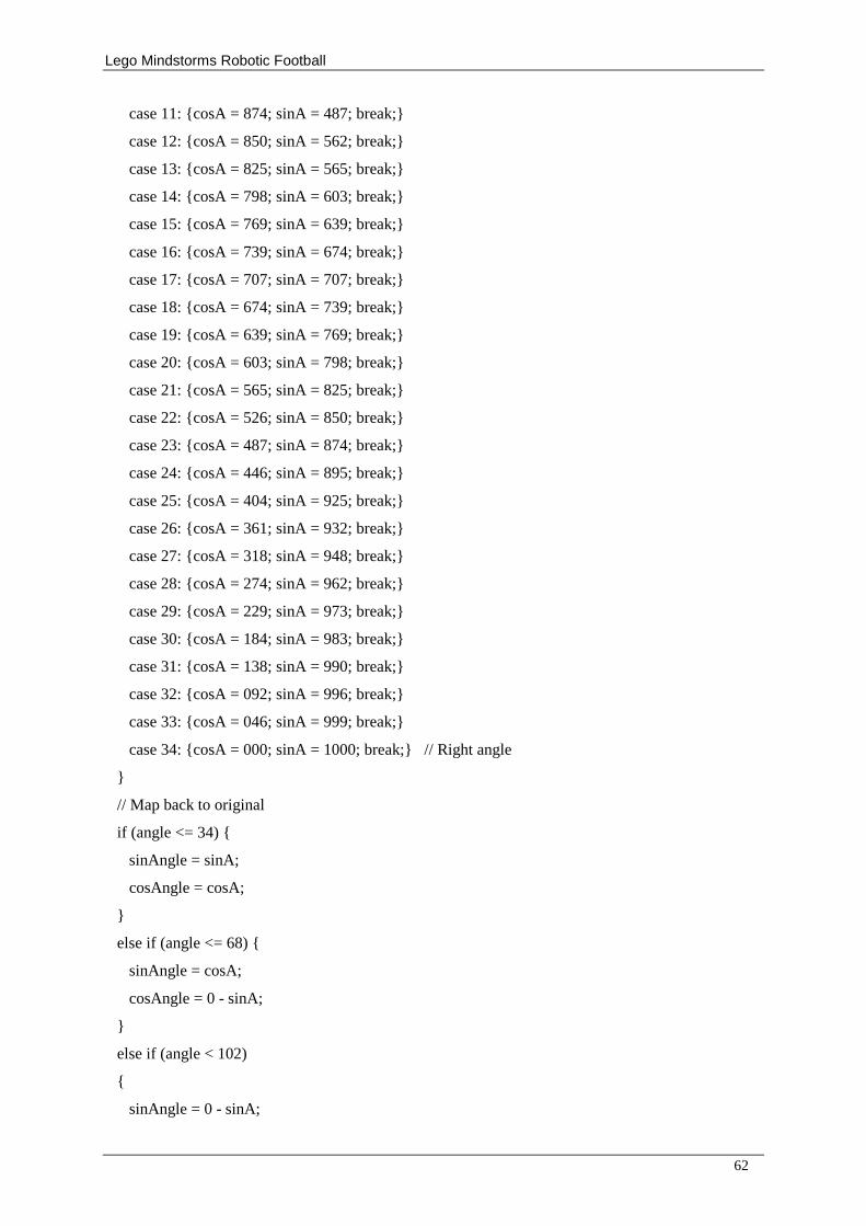
Lego Mindstorms Robotic Football
62
case 11: {cosA = 874; sinA = 487; break;}
case 12: {cosA = 850; sinA = 562; break;}
case 13: {cosA = 825; sinA = 565; break;}
case 14: {cosA = 798; sinA = 603; break;}
case 15: {cosA = 769; sinA = 639; break;}
case 16: {cosA = 739; sinA = 674; break;}
case 17: {cosA = 707; sinA = 707; break;}
case 18: {cosA = 674; sinA = 739; break;}
case 19: {cosA = 639; sinA = 769; break;}
case 20: {cosA = 603; sinA = 798; break;}
case 21: {cosA = 565; sinA = 825; break;}
case 22: {cosA = 526; sinA = 850; break;}
case 23: {cosA = 487; sinA = 874; break;}
case 24: {cosA = 446; sinA = 895; break;}
case 25: {cosA = 404; sinA = 925; break;}
case 26: {cosA = 361; sinA = 932; break;}
case 27: {cosA = 318; sinA = 948; break;}
case 28: {cosA = 274; sinA = 962; break;}
case 29: {cosA = 229; sinA = 973; break;}
case 30: {cosA = 184; sinA = 983; break;}
case 31: {cosA = 138; sinA = 990; break;}
case 32: {cosA = 092; sinA = 996; break;}
case 33: {cosA = 046; sinA = 999; break;}
case 34: {cosA = 000; sinA = 1000; break;} // Right angle
}
// Map back to original
if (angle <= 34) {
sinAngle = sinA;
cosAngle = cosA;
}
else if (angle <= 68) {
sinAngle = cosA;
cosAngle = 0 - sinA;
}
else if (angle < 102)
{
sinAngle = 0 - sinA;
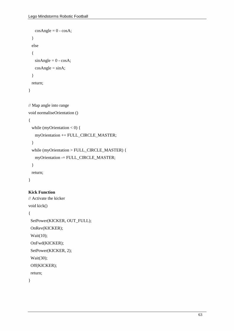
Lego Mindstorms Robotic Football
63
cosAngle = 0 - cosA;
}
else
{
sinAngle = 0 - cosA;
cosAngle = sinA;
}
return;
}
// Map angle into range
void normaliseOrientation ()
{
while (myOrientation < 0) {
myOrientation += FULL_CIRCLE_MASTER;
}
while (myOrientation > FULL_CIRCLE_MASTER) {
myOrientation -= FULL_CIRCLE_MASTER;
}
return;
}
Kick Function // Activate the kicker
void kick()
{
SetPower(KICKER, OUT_FULL);
OnRev(KICKER);
Wait(10);
OnFwd(KICKER);
SetPower(KICKER, 2);
Wait(30);
Off(KICKER);
return;
}
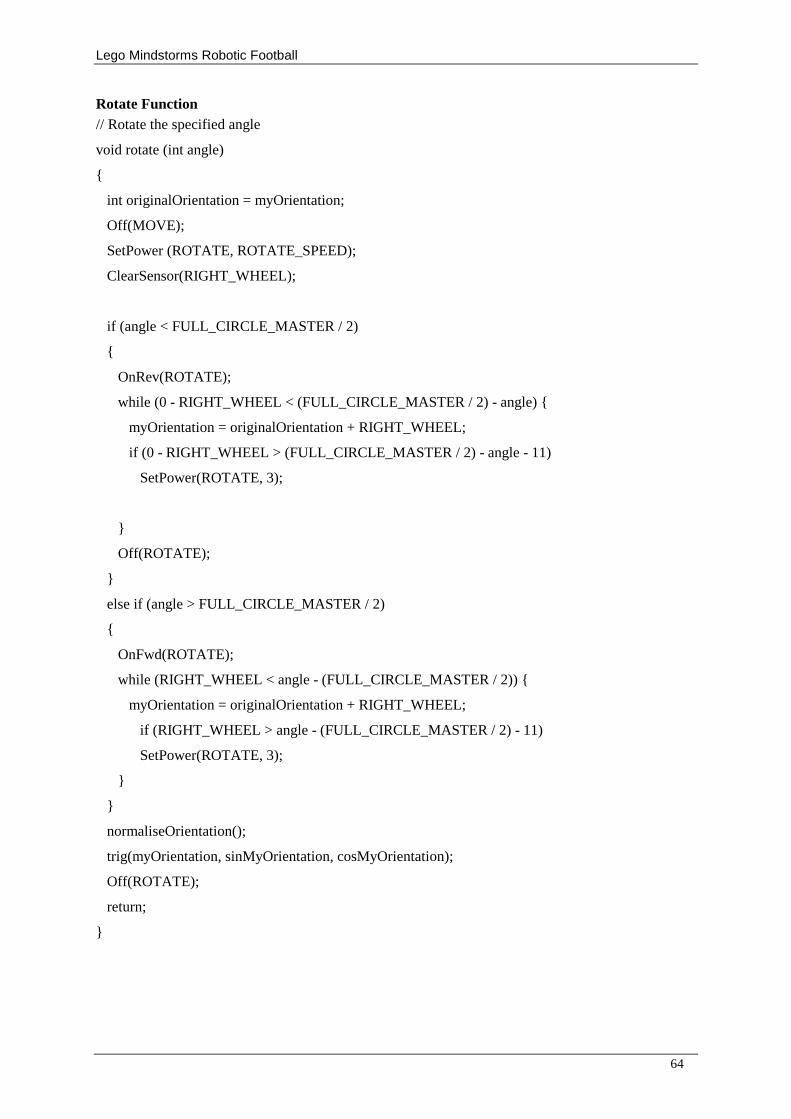
Lego Mindstorms Robotic Football
64
Rotate Function // Rotate the specified angle
void rotate (int angle)
{
int originalOrientation = myOrientation;
Off(MOVE);
SetPower (ROTATE, ROTATE_SPEED);
ClearSensor(RIGHT_WHEEL);
if (angle < FULL_CIRCLE_MASTER / 2)
{
OnRev(ROTATE);
while (0 - RIGHT_WHEEL < (FULL_CIRCLE_MASTER / 2) - angle) {
myOrientation = originalOrientation + RIGHT_WHEEL;
if (0 - RIGHT_WHEEL > (FULL_CIRCLE_MASTER / 2) - angle - 11)
SetPower(ROTATE, 3);
}
Off(ROTATE);
}
else if (angle > FULL_CIRCLE_MASTER / 2)
{
OnFwd(ROTATE);
while (RIGHT_WHEEL < angle - (FULL_CIRCLE_MASTER / 2)) {
myOrientation = originalOrientation + RIGHT_WHEEL;
if (RIGHT_WHEEL > angle - (FULL_CIRCLE_MASTER / 2) - 11)
SetPower(ROTATE, 3);
}
}
normaliseOrientation();
trig(myOrientation, sinMyOrientation, cosMyOrientation);
Off(ROTATE);
return;
}
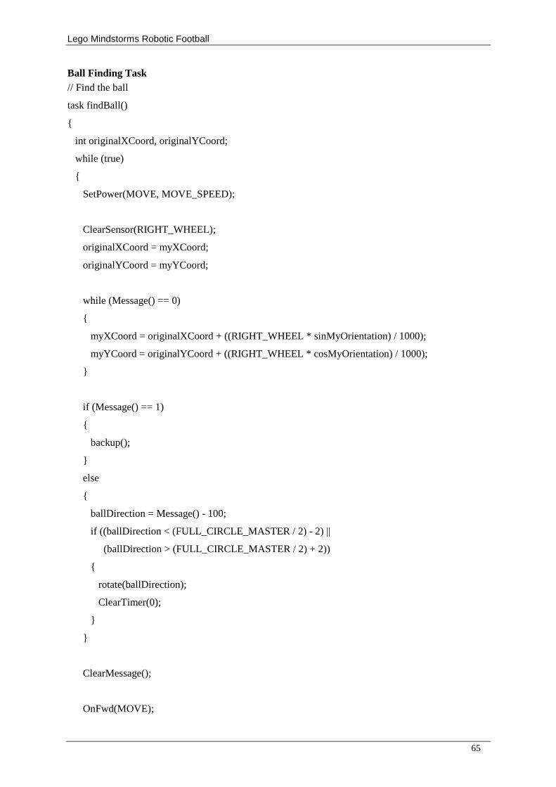
Lego Mindstorms Robotic Football
65
Ball Finding Task // Find the ball
task findBall()
{
int originalXCoord, originalYCoord;
while (true)
{
SetPower(MOVE, MOVE_SPEED);
ClearSensor(RIGHT_WHEEL);
originalXCoord = myXCoord;
originalYCoord = myYCoord;
while (Message() == 0)
{
myXCoord = originalXCoord + ((RIGHT_WHEEL * sinMyOrientation) / 1000);
myYCoord = originalYCoord + ((RIGHT_WHEEL * cosMyOrientation) / 1000);
}
if (Message() == 1)
{
backup();
}
else
{
ballDirection = Message() - 100;
if ((ballDirection < (FULL_CIRCLE_MASTER / 2) - 2) ||
(ballDirection > (FULL_CIRCLE_MASTER / 2) + 2))
{
rotate(ballDirection);
ClearTimer(0);
}
}
ClearMessage();
OnFwd(MOVE);
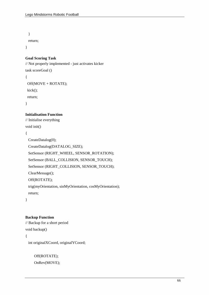
Lego Mindstorms Robotic Football
66
}
return;
}
Goal Scoring Task // Not properly implemented - just activates kicker
task scoreGoal ()
{
Off(MOVE + ROTATE);
kick();
return;
}
Initialisation Function // Initialise everything
void init()
{
CreateDatalog(0);
CreateDatalog(DATALOG_SIZE);
SetSensor (RIGHT_WHEEL, SENSOR_ROTATION);
SetSensor (BALL_COLLISION, SENSOR_TOUCH);
SetSensor (RIGHT_COLLISION, SENSOR_TOUCH);
ClearMessage();
Off(ROTATE);
trig(myOrientation, sinMyOrientation, cosMyOrientation);
return;
}
Backup Function // Backup for a short period
void backup()
{
int originalXCoord, originalYCoord;
Off(ROTATE);
OnRev(MOVE);
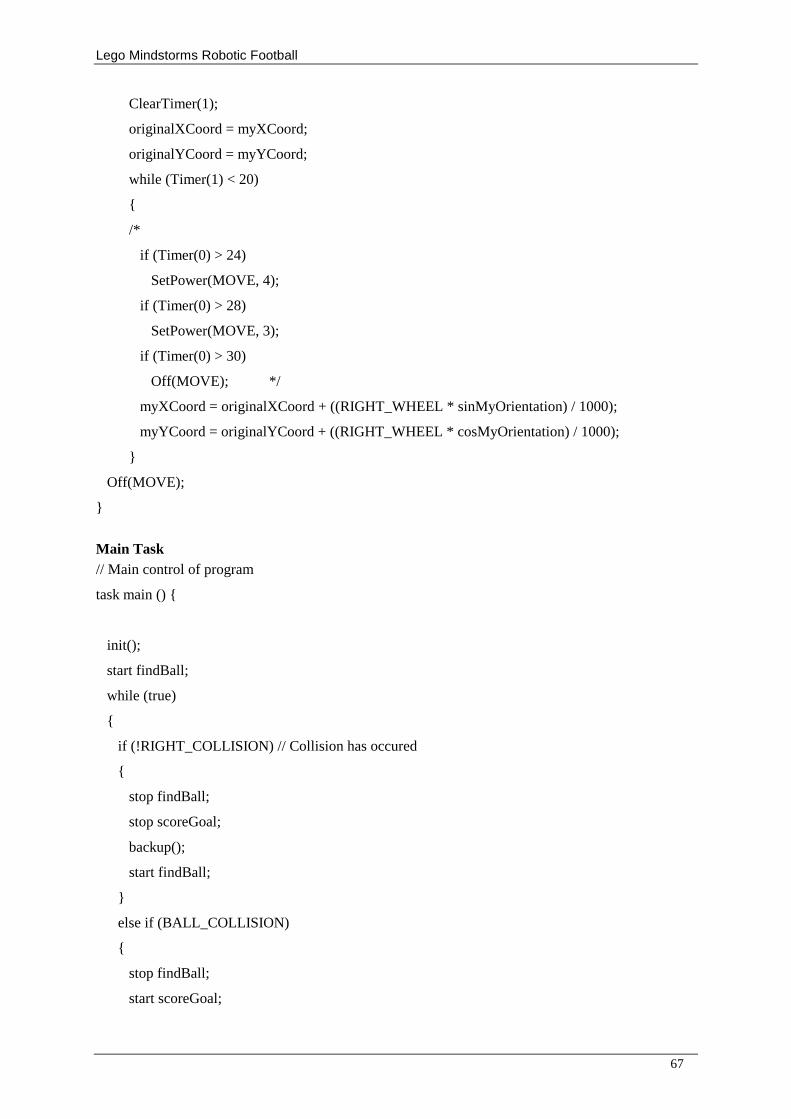
Lego Mindstorms Robotic Football
67
ClearTimer(1);
originalXCoord = myXCoord;
originalYCoord = myYCoord;
while (Timer(1) < 20)
{
/*
if (Timer(0) > 24)
SetPower(MOVE, 4);
if (Timer(0) > 28)
SetPower(MOVE, 3);
if (Timer(0) > 30)
Off(MOVE); */
myXCoord = originalXCoord + ((RIGHT_WHEEL * sinMyOrientation) / 1000);
myYCoord = originalYCoord + ((RIGHT_WHEEL * cosMyOrientation) / 1000);
}
Off(MOVE);
}
Main Task // Main control of program
task main () {
init();
start findBall;
while (true)
{
if (!RIGHT_COLLISION) // Collision has occured
{
stop findBall;
stop scoreGoal;
backup();
start findBall;
}
else if (BALL_COLLISION)
{
stop findBall;
start scoreGoal;
Lego Mindstorms Robotic Football
68
ClearTimer(2);
}
else
{
if (Timer(2) == 20)
{
stop scoreGoal;
start findBall;
}
}
}
return;
}
D.2 Code for Slave RCX #define EYE SENSOR_2
#define ANGLE SENSOR_3
#define NECK OUT_A
#define FULL_CIRCLE_SLAVE 56
#define FULL_CIRCLE_MASTER 136
#define DATALOG_SIZE 500
#define THRESHOLD 45
int maxIntensity;
int ballAngle;
int lastAngle;
int msg;
int stalledCounter;
Calibration Function // Calibrates the ball finder
void calibrate ()
{
// Align the haed
ClearSensor(ANGLE);
SetPower(NECK, 5);
OnRev(NECK);
Lego Mindstorms Robotic Football
69
lastAngle = 10;
while (ANGLE < lastAngle - 2 || ANGLE > lastAngle + 2)
{
lastAngle = ANGLE;
Wait(20);
}
ClearSensor(ANGLE);
}
Main Task // Controls the ball finder
task main () {
int lastAngle;
CreateDatalog(0);
CreateDatalog(DATALOG_SIZE);
SetSensor(EYE, SENSOR_LIGHT);
SetSensor(ANGLE, SENSOR_ROTATION);
calibrate();
ClearMessage();
stalledCounter = 0;
while (true)
{
OnFwd(NECK);
ClearTimer(0);
maxIntensity = 0;
lastAngle = -1;
SetPower (NECK, 10);
int maxAngle = FULL_CIRCLE_SLAVE - 5;
while (ANGLE < maxAngle)
{
// If new light reading is greater than max
if (EYE > maxIntensity)
Lego Mindstorms Robotic Football
70
{
// Update max
maxIntensity = EYE;
ballAngle = ANGLE;
}
if (ANGLE == FULL_CIRCLE_SLAVE - 8)
SetPower (NECK, 2);
if (ANGLE > lastAngle) {
AddToDatalog(ANGLE);
AddToDatalog(EYE);
lastAngle = ANGLE;
}
lastAngle = ANGLE;
}
msg = (((ballAngle * FULL_CIRCLE_MASTER)) /
FULL_CIRCLE_SLAVE) + 100;
ClearMessage();
Off(NECK);
SendMessage(msg);
Wait(10);
OnRev(NECK);
maxIntensity = 0;
SetPower (NECK, 10);
stalledCounter= 0;
int minAngle = 5;
while (ANGLE > minAngle)
{
if (ANGLE == 8)
SetPower (NECK, 2);
// If new light reading is greater than max
if (EYE > maxIntensity)
{
Lego Mindstorms Robotic Football
71
// Update max
maxIntensity = EYE;
ballAngle = ANGLE;
}
lastAngle = ANGLE;
}
msg = ((ballAngle * FULL_CIRCLE_MASTER) /
FULL_CIRCLE_SLAVE) + 100;
ClearMessage();
Off(NECK);
SendMessage(msg);
Wait(10);
}
}
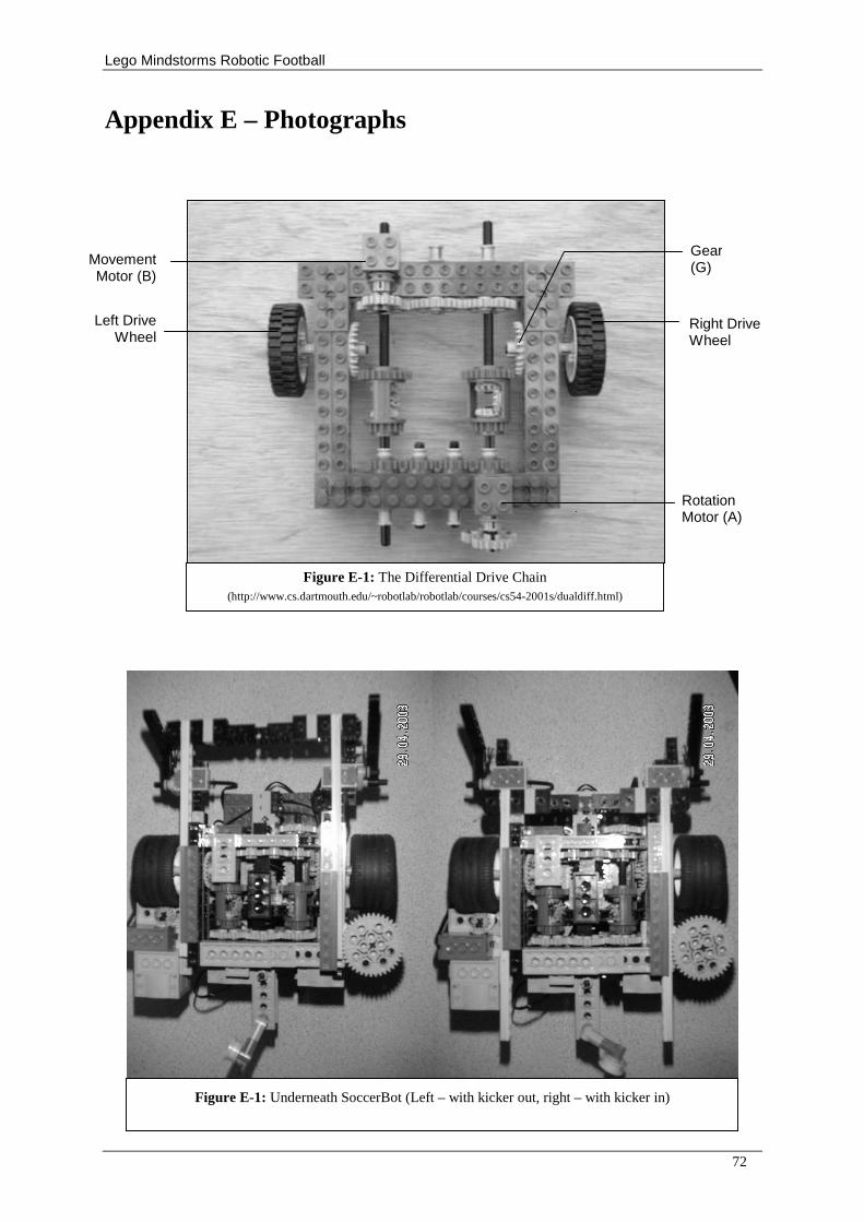
Lego Mindstorms Robotic Football
72
Appendix E – Photographs
Figure E-1: The Differential Drive Chain (http://www.cs.dartmouth.edu/~robotlab/robotlab/courses/cs54-2001s/dualdiff.html)
Movement Motor (B)
Rotation Motor (A)
Gear (G)
Left Drive Wheel
Right Drive Wheel
Figure E-1: Underneath SoccerBot (Left – with kicker out, right – with kicker in)
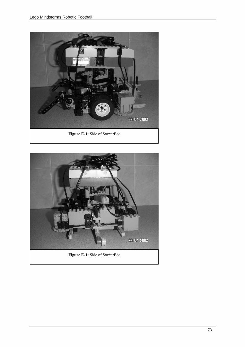
Lego Mindstorms Robotic Football
73
Figure E-1: Side of SoccerBot
Figure E-1: Side of SoccerBot
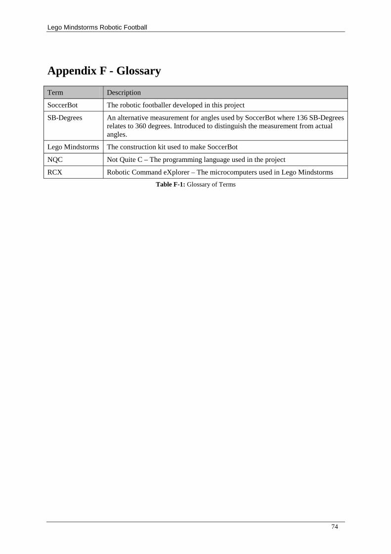
Lego Mindstorms Robotic Football
74
Appendix F - Glossary
Term Description
SoccerBot The robotic footballer developed in this project
SB-Degrees An alternative measurement for angles used by SoccerBot where 136 SB-Degrees relates to 360 degrees. Introduced to distinguish the measurement from actual angles.
Lego Mindstorms The construction kit used to make SoccerBot
NQC Not Quite C – The programming language used in the project
RCX Robotic Command eXplorer – The microcomputers used in Lego Mindstorms
Table F-1: Glossary of Terms