Embed Size (px)
Citation preview
SE . /~·
( ~ROJECT FIRE MODEL
Summary Progress Report - II
Period May 1, 1960, to April 30, 1962
by
W. L. Fons H. B. Clements
E. R. Elliott P. M. George
Forest Service, U. S. Department of Agriculture Southeastern Forest Experiment Station
Southern Forest Fire Laboratory · Macon, Georgia
ACKNOWLEDGMENT
The authors express their thanks to the Office of Civil Defense for providing financial support through contracts administered by the National Bureau of Standards and to the Forest Research Council of the State of Georgia for making facilities available. Credit for assisting in the experimental work, data reduction and calculations is due to R. K. Burgess and M. E. Bishop, of the Southern Forest Fire Laboratory. Finally, the authors express their thanks to H. D. Bruce. W. Y. Pong, and S. S. Richards, of the Pacific Southwest Forest and Range Experiment Station, for their contributions in the initial experimental work.
Material in several sections of this report was presented by W. L. Fans in a paper entitled "Use of Models to Study Forest Fire Behavior" at the Tenth Pacific Science Congress of the Pacific Science Association, held at the University of Hawaii, Honolulu, August 21 to September 6, 1961. The congress was sponsored by the National Academy of Sciences, Bernice Pauahi Bishop Museum. and the University of Hawaii.
CONTENTS
INTRODUCTION . . . . . . .
EXPERIMENTAL CONDITIONS
RESULTS AND DISCUSSION
1. Heat Value of Wood
2. Equilibrium Moisture Content of White Fir Wood
3. Crib Fire with Side Airflow Restricted . . . .
4. Influence of Species of Wood on Rate of Spread
5. Influence of Specific Gravity and Moisture Content of Wood on Rate of Fire Spread
6. Flame Dimension Correlation .
7. Burning Time Correlation
8. Convective Heat
9. Radiative Heat
10. Flame Emissivity
11. Temperature of Convection Column
CONCLUSIONS
PLANS FOR CONTINUATION
NOMENCLATURE
REFERENCES
APPENDIX A - Experimental Data
APPENDIX B - Geometrical View Factor
Page
1
2
6
6
8
10
10
12
14
17 ,, 24
25
31
33
37
38
. . . . 40
43
45
52
PROJECT FIRE MODE~/
Summary Progress Report - II
Period May 1, 1960 to April 30, 1962
by
W. L. Fans H. B. Clements E. R. Elliott P. M. George
Southern Forest Fire Laboratory Southeastern Forest Experiment Station
Forest Service, U.S.D.A.
INTRODUCTION
The general objectives of this project are to evaluate the
effects of the independent variables of fuel, fuel bed, fuel base,
and atmospheric conditions on the dependent variables such as rate
of burning, flame size, rate of energy released, and others which
are concerned with the spread and control of fires burning in solid
fuel . Detailed objectives, scope, and importance of the project and
a work plan are presented in an earlier report (Fons et al., 1960).
The immediate aim of the project is to explain by means of reliable
data the behavior of a laboratory-scale fire burning solid fuels in
an unconfined atmosphere. No attempt is made in this r eport to
establish quantitative relations between laboratory-scale and full-
scale building or forest fires.
1/ This research was originally sponsored by the Office of Civil and Defens e Mobilization (OCDM Contract DCM-SR-59-10) and since April 1960 continued under contract with the National Bureau of Standards (NBS Order No. 35372-60, April 14, 1960, as amended, and NBS Order No. S-302190-62, February 28, 1962).
-1-
The propagating flame model selected for study permits
establishment of a steady-state condition (Fons et al., 1959) for
the free-burning of solid fuels. With this model the parameters
which govern combustion can be examined and measured over an extended
period of time. The model repre-sents on a reduced scale a section of
the combustion zone of a moving fire front burning in a homogeneous
fuel bed without spotting.
To date about 100 experimental fires have been burned using
this st~ady-state model. Measurements of the dependent and independent
variables were analyzed to establish quantitative relationships between
certain fire properties and the fuel and fuel bed parameters. For
example, a functional relationship between flame dimensions and the
rate of burning was verified. Also, a correlation was found between
dimensionless groups containing burning time, flame length, and those
parameters which describe the physical properties and the geometry of
the fuel and the fuel bed.
EXPERIMENTAL CONDITIONS
The essential elements of the fire model are: a wood fuel bed
built in the form of a crib, a combustion table equipped to t ransport
the fuel bed at a controlled rate, an ignition device, a base of inert
material of known density, and sensing and recording instruments to
measure specific variabl es (Fons et al., 1959).
,,
The fuel bed is a crib of wood sticks of square cross section.
The physical features of such a fuel bed can be controlled. For
example, the species, density, moisture content, size and spacing of
the wood sticks, and the width and height of the fuel bed are all
selected before the crib is built. The crib is formed by placing the
sticks i n t i ers wi th the selected spacing between sticks . A drop of
resor cinol-formal dehyde resin glue is placed on each junction to bond
the crib into a r i gid assembly . For several weeks before burning, the
crib is conditioned to an equi librium moisture content in an atmos
phere of constant temperature and relative humidity .
The ignition device is a narrow, shallow trough containi ng an
asbestos wick satur ated with a liquid hydrocarbon. This device is
placed at one end of the crib. The liquid hydrocarbon is ignited to
initiate combustion in the fuel bed. The fire gradually spreads to
the other end of the crib, reducing the wood to a residue of ash and
charcoal.
The combustion table is equipped with a chain-belt mechanism
which moves the crib and two heavy asbestos sheets, one on each side
of the fire, in synchroni sm with the flame spread to simulate move
ment of the fire front relative to the ground . The crib and its
inert base rest on the chain-belt, which is moved manually by a gear
drive in order to hold the flaming zone of the burning crib in a
fixed position .
The combustion gases diluted by the entrained air are expelled
from the room through a 2-foot - diameter exhaust stack. The incoming
- 3 -
conditioned air is supplied to the room at a rate of about 5,000 cubic
feet per minute through several louvered outlets in a continuous duct
located near the ceiling around the room. The entrance to the stack
is a hood 12 feet in diameter and located 12 feet above the combustion
table.
Time-lapse cameras mounted on the wall photograph the test
fires for subsequent measurements of flame depth and length. Three
grids of thermocouples suspended at different levels above the com
bustion table measure temperatures of the convection column. A
thermocouple and a Pi tot tube mounted in the exhaust stack measure
the temperature and velocity of combustion gases. Thermopile radi
ometers located at the front, rear, and side of the test fire measure
radiation. The sensing elements are connected to recording instruments
in a control room adjacent to the combustion room .
Two important features of the model are: (1) The crib is made
relatively long and a zone of fire travels the length of the crib.
After an initial buildup, the rate of burning or spread reaches a
constant value, which holds until near the end, and thus the diffi
culty of investigating a fire burning under transient conditions is
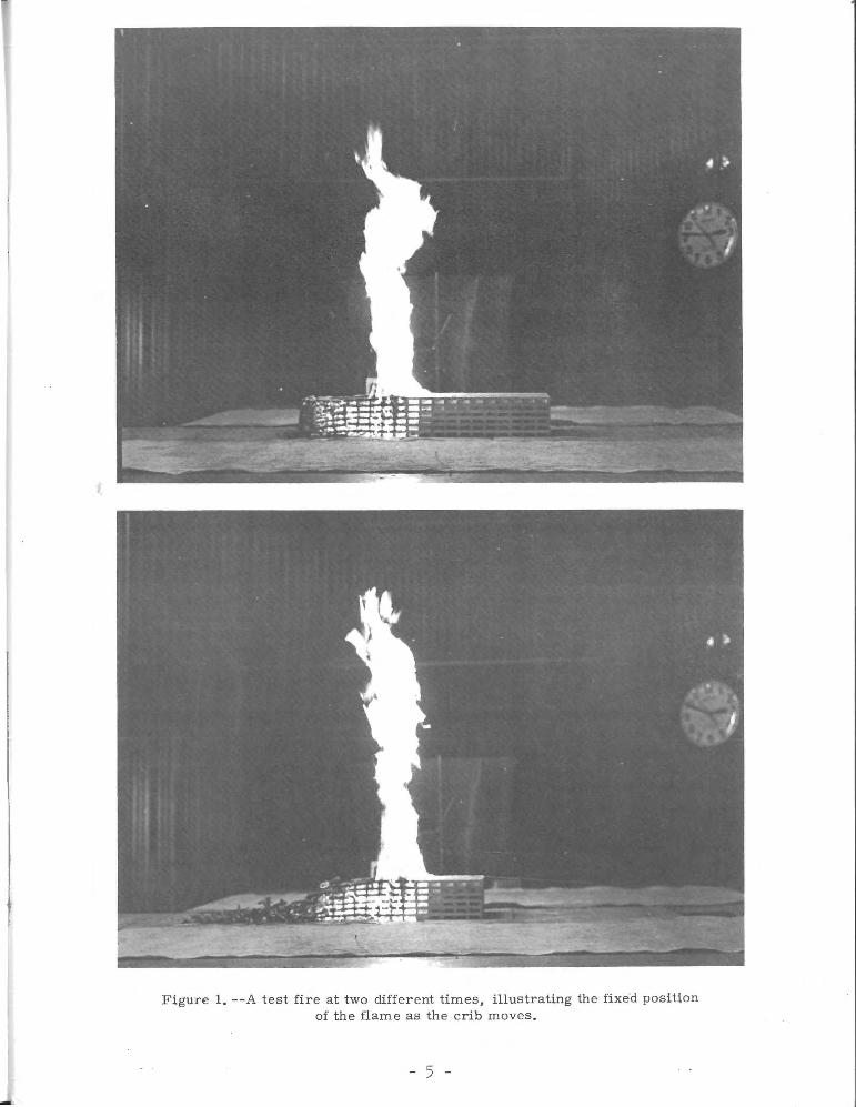
avoided. (2) The position of the flaming zone is held fixed in space
by moving the fuel into the fire . This method permits the grids of
thermocouples in the flame and convection column, radiometers surround
ing the fire, and other sensing devices to be stationary. The rate of
fire spread is equal to the rate the crib is moved to maintain the
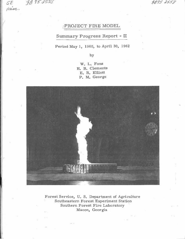
flame in a fixed position (fig. 1).
,I
-
Figure 1. --A test fire at two different times, illustrating the fixe'd position of the flame as the crib moves.
- 5 -
Physical characteristics of the wood, the crib, and the en
vironment during the burning period for each crib fire are present ed
in Appendix A, tables 4 and 5. The room temperatures in these tables
are the arithmetic means of readings taken before and after each test
fire.
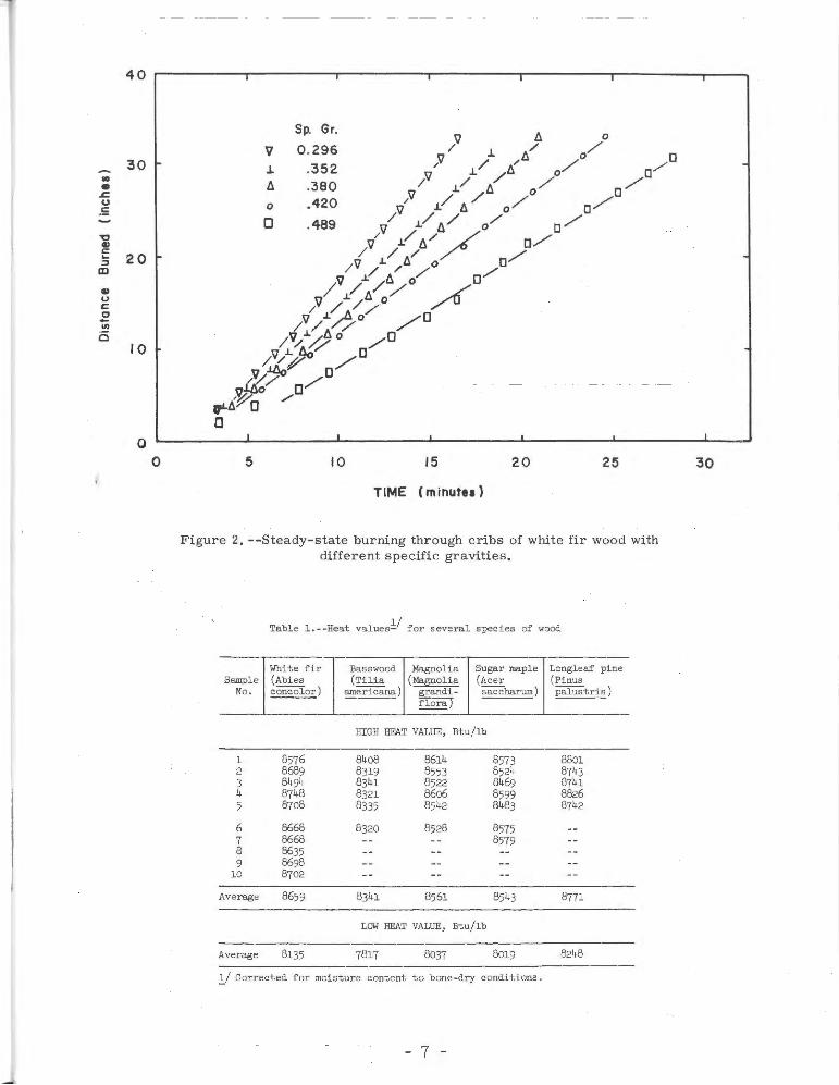
The duration of the steady-state burning period is limited only
by the buildup time and the length of the crib. The time for the burn
ing to reach a steady-state condition after one end of the crib is
ignited depends upon such factors as spacing, density, size and
moisture content of the wood sticks. Figure 2 presents curves show
ing the steady-state periods for the spread of fire through cribs of
wood with different specific gravities.
RESULTS AND DISCUSSION
Analyses were made of data from the crib fires to determine
quantitative relationships between the several aspects of fire be
havior, such as radiative and convective heat, flame dimensions ,
emissivity, and rate of spread. The experimental data used in the
analyses are presented in Appendix A.
1 . Heat Value of Wood
Samples of each species of wood covering the ful l range of
densities were reduced to sawdust, molded into pellets, and dried
in a desiccator over calcium chl oride. The heat values for these
samples were determined by an Emerson, adiabatic -type, bomb calo
rimeter . The high heat values (with moisture condensed to liquid)
are presented in table 1.
• • .c u .5
40
30
20
10
0 0
l
5
v .1.
fl 0
0
I
Sp. Gr.
0.296 .352 .380 . 420
.489
10
I I
15 20 25
TIME Cminutu)
Figure 2. --Steady-state burning through cribs of white fir wood with different spe cific gravities.
Table 1 . --Heat valuesl/ for several speci es of wood
White fir Basswood Magnolia Sugar maple Longleaf pine Sampl e (Abi es (Tilia (Magnolia (Acer (Pinus
No . concolor ) ameri cana) ~- saccharum ) palustris) ra
HIGH HEAT VALUE, Btu/lb
1 8576 8408 8614 8573 8801 2 8689 8319 8553 8524 8743 3 8494 8341 8522 8469 8741 4 8748 8321 86o6 8599 8826 5 87o8 8335 8542 8483 8742
6 8668 8320 8528 8575 7 8668 8579 8 8635 9 8698
10 8702
Average 8659 8341 8561 8543 8771
LOW HEAT VALUE, Btu/lb
Average 8135 7817 8037 8019 8248
l / Cor rected for moi sture content to bone-dry conditions.
- 7 -
I
30
In the test fires, the moisture from the fuel does not condense
as it does in the bomb calorimeter. Therefore, the low heat value
(with moi sture in vapor form) is of greater interest than the high heat
value. From the measured high heat value of the wood, the low heat
value was calculated by assuming that wood is 50 percent carbon, 44
percent oxygen, and 6 percent hydrogen, and on burning forms 0 . 539 lb.
of water vapor for each pound of dry wood. The water vapor, due to
its latent heat of vaporization, reduces the high heat value by
0 . 539 x 972, or 524 Btu/ lb. The low heat values for each species of
wood, found by subtracting 524 Btu/lb from the high heat values , are
also tabulated at the bottom of table 1.
2. Equilibrium Moisture Content of White Fir Wood
The selection and control of the relative humidity of the air
supplied t o the combustion room were essential in assuring that the
moisture content of cribs remains constant during experimental fires.
The relative humidity for a given test fire was selected from an
equilibrium moistur e content curve for wood . For this purpose, an
equilibrium moistur e content curve was established for white fir
wooa (fig. 3) .
The points on the curve represent the equilibrium moisture
content of 25 white fir dowels, 3/8-inch diameter and 9 inches long .
The dowel s were exposed to selected re l ative humidities at room
0 temperature 70 F . The relative humidities were produced by satu -
rated salt solutions placed in desiccators. After the dowels had
been exposed to the conditions in the desiccators for a period of
five months, they were wei ghed to determine their equilibrium
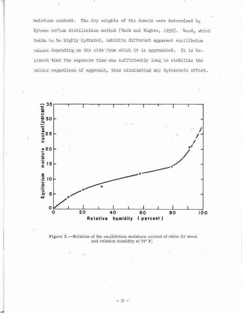
moi sture content . The dry weights of the dowels were determined by
Xylene reflux di sti llation method (Buck and Hughes , 1939). Wood, which
tends to be h i ghly hydrated, exhi bi ts di ffe r ent apparent equili br ium
values dependi ng on the side from which it is appr oached . I t i s be -
l ieved that the exposure time was suffici ently l ong to stabilize the
va lues regardl ess of approach, t hus eliminati ng any hyst eresis effect.
E 0~
I I
I -'
./ :1 10 ... :!!
40 60 eo Relative humidity C percent)
Figure 3. --Relation of the equilibrium moisture cont ent of white fir wood and relative humidity at 70° F.
- 9 -
100
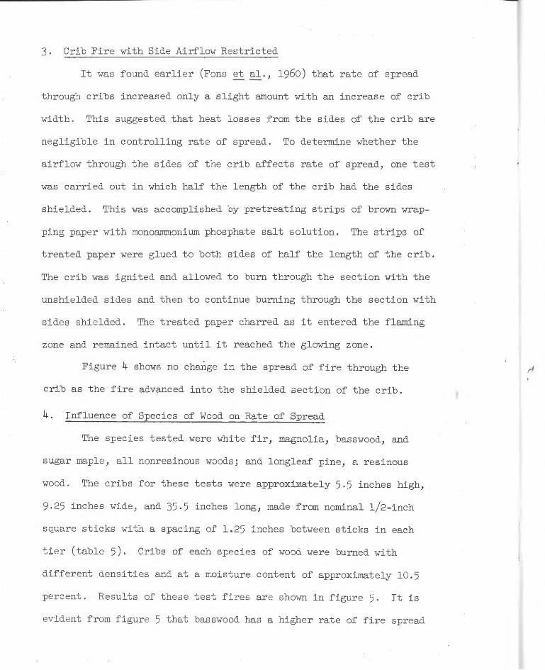
3. Crib Fire with Side Airflow Restricted
It was found earlier (Fons et al., 1960) that rate of spread
through cribs increased only a slight amount with an increase of crib
width. This suggested that heat losses from the sides of the crib are
negligible in controlling rate of spread. To determine whether the
airflow through the sides of the crib affects rate of spread, one test
was carried out in which half the length of the crib had the sides
shielded. This was accomplished by pretreating strips of brown wrap
ping paper with monoammonium phosphate salt solution. The strips of
treated paper were glued to both sides of half the length of the crib.
The crib was ignited and allowed to burn through the section with the
unshielded sides and then to continue burning through the section with
sides shielded. The treated paper charred as it entered the flaming
zone and remained intact until it reached the glowing zone .
Figure 4 shows no change in the spread of fire through the
crib as the fire advanced into the shielded section of the crib .
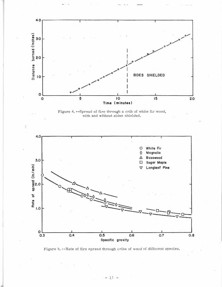
4. Influence of Species of Wood on Rate of Spread
The species tested were white fir, magnolia, basswood, and
sugar maple, all nonresinous woods; and longleaf pine, a resinous
wood. The cribs for these tests were approximately 5 . 5 inches high,
9.25 inches wide, and 35 .5 inches long, made from nominal l/2 - inch
square sticks with a spacing of 1.25 inches between sticks in each
tier (table 5). Cribs of each species of wood were burned with
different densities and at a moisture content of approximately 10.5
percent . Results of these test fires are shown in figure 5. It is
evident from figure 5 that basswood has a higher rate of fire spread
~'
40r-------------~,--------------~.------------~,---------------
-.. ~ 301-CJ c
o/ 0/
o/
• ~ c 0 -en 0 10
0
: 0~ I o/ 0/
o/1 /
0/
,.o /0 I SIDES SHIELDED
/o I /o I
-
.
o~----------o-/--~·-------------~·---1 __________ ._. ____________ ~ 0 S 10 IS
Ttmt ( minutu)
Figure 4. --Spread of fire through a crib of white fir wood, with and without sides shielded.
:5 E
4.0
3.0
:0 ~ ~2.0 "0 ~ ~ '- ~A . ~ -.......... ~ ~d"¢¢...,A A----
'Ov~() • .. 0
a; 1.0 ~0~ -v~~
0 White Fir ¢ Magnolia A Basswood 0 Sugar Maple
'il Longleaf Pine
20
v- -v --o-B -v- --o--v---
0~----------~----------_. __________ ~~----------L-----------~ 0.3 0.4 o.s 0 .6 0.7 0.8
Specific gravity
Figure 5. --Rate of fire spread through cri bs of wood of different species.
- ll -
than the other four species. This would indicate that some wood
property other than density also has an effect on rate of burning.
Basswood has an oil, rich in volatile fatty acids (Wise and Jahn,
1952, p. 563 ), and this may account for the higher rate of burning.
On the other hand, longleaf pine, a resinous wood, has practically
the same rate of spread as white fir, maple, and magnolia. The results
for longleaf pine indicate that resin in wood does not increase the
rate of burning; in factJ it appears to act as a r etardant .
5. Influence of Specific Gravity and Moisture Content
of Wood on Rate of Fire Spread
Six series of cribs were burned to determine the effect of
specific gravity of wood on rate of fire spread for different moisture
contents. The cribs were approximately 5.5 inches highJ 9.25 inches
wide, 35.5 inches long, and made from nominal l/2-inch square sticks
with spacing of 1.25 inches between sticks in each tier (table 4) .
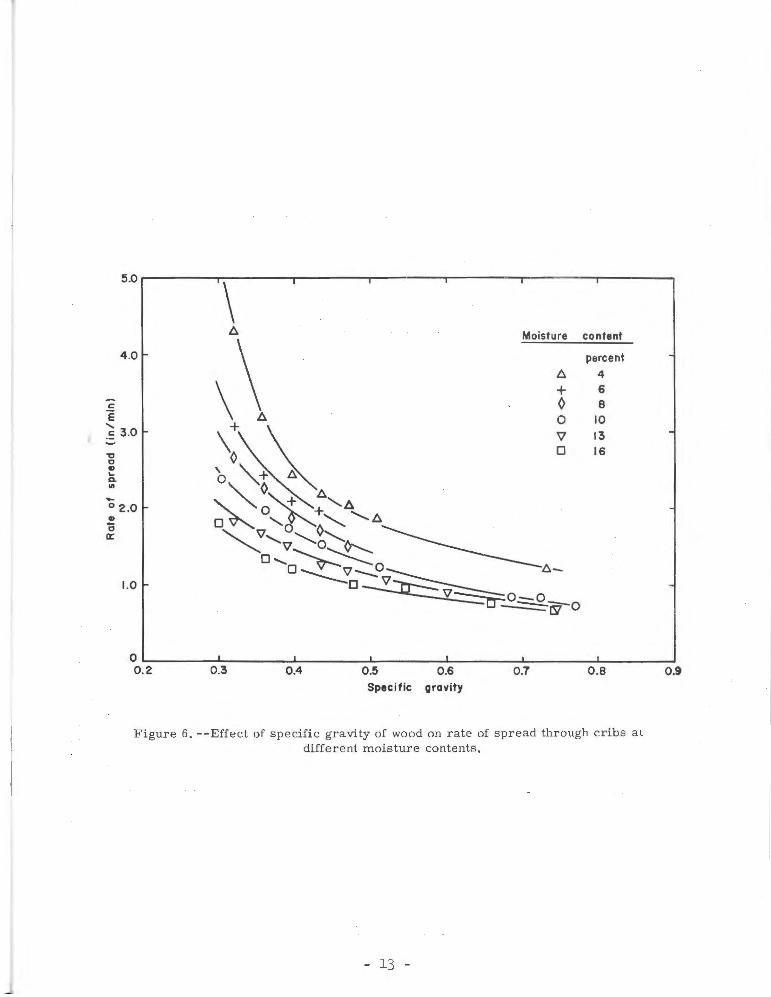
As shown in figure 6J the rate of spread increases rapidly with de
creasing moisture content for specific gravities less than 0. 45 and
moisture contents less than 10 percent. Since litter, bark, moss ,
grass, leaves, and partially decomposed wood have specific gravities
somewhat less than 0.45 and are the fuels which contribute largely to
the spread of most forest firesJ it is apparent that moisture content
and specific gravity of these fuels are important.
,,
5.0~\--,----r------r-~~
4.0
-c ·e ...... . ~ 3.0
, 0 Cl .... Q,
"' .... 0 2 .0 Cl
0 a:
1.0
~
\\ \~ b "~"~ ,~~~""':'~ 0~ ·,~, ........... ~
Moisture
+ 0 0 v 0
~'v'~'~ o ...... ~~ 0~0--0~ ~-
~o---?.::::g.jy-0
content
percent
4 6 8
10 13 16
0~------~--------~--------~--------._------~~-------L--------~ 0.2 0.3 0.4 0.5 0.6 0.7 0.8 Specific gravity
Figure 6. --Effect of specific gravity of wood on rate of spread through cribs at different moisture contents.
- 13 -
0.9
6. Flame Dimension Correlation
When buoyant combustible gases emerge from a burning fuel bed
into an unconfined atmosphere where they burn as a flame, the rate of
oxygen diffusion into the gaseous fuel stream determines the length of
the flame. For free-convection fires this diffusion of oxygen controls
the rate of burning of the fuel per unit area of the burning zone. A
detailed derivation of a simple dimensionless relationship between
flame dimensions and rate of burning for buoyant diffusion flames, in-
eluding a discussion of the work of others, can be found in the paper
by Thomas et al., (1961).
The derived dimensionless relationship of the flame dimensions
with the modified Froude number containing the combustion gas velocity,
v, is
(1)
Assuming that the temperature of the combustion gases emerging
from the fuel in the flaming zone is the same for the different fires
and that it is equal to the flame temperature of 1650° F., then the
velocity, V, of the gases is calculated by the relation
(2)
The term, C, is the weight of gas produced per unit weight of solid
fuel. For conditions of complete combustion (Kawagoe, 1958), no
excess air, and gas temperature at 1650° F., C = 6.13, and p = g
0.019 lb/ft3 . The flame dimensions can be expressed in terms of
the rate of burning per unit area, G, by combining equations 1 and 2
(3)
From time-lapse motion pictures taken during the steady-state
burning period, measurements of flame length, L, and depth of flaming
zone, D, were made of 66 crib fires. These cribs were of varying
widths and heights and contained wood of varying densities, fuel sizes,
and moisture contents; but, in this flame dimension correlation it is
assumed that the fuel and fuel bed parameters are important only in
their effect on G, the rate of burning. The rate of burning per unit
area, G, of each crib was calculated by the equation
(4)
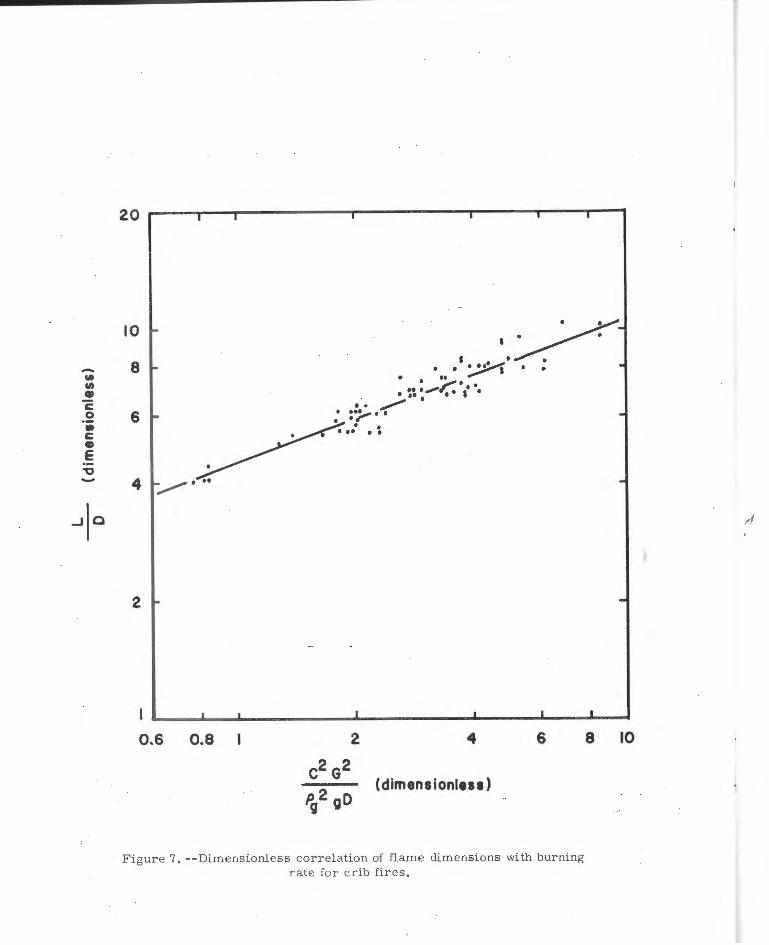
Since for most of the fires burned, the ratios of the flaming zone, D,
to the width of the crib, wb, were less than 1.0, i.e., D/wb < 1.0,
then the advancing flaming zone for these fires may be considered,
ideally, a semi-infinite strip or line fire. Dimensionless correlation
of flame dimensions with burning rate for crib fires is shown in
figure 7 and the equation for the line is
( 5)
- 15 -
-.. Cit • ~ .2 • c • e ., -
10
8
6
4
2
0 .6 0.8 2 4 6
(dimensionless)
Figure 7. --Dimensionless correlation of flame dimensions with burning rate for crib fires.
8 10
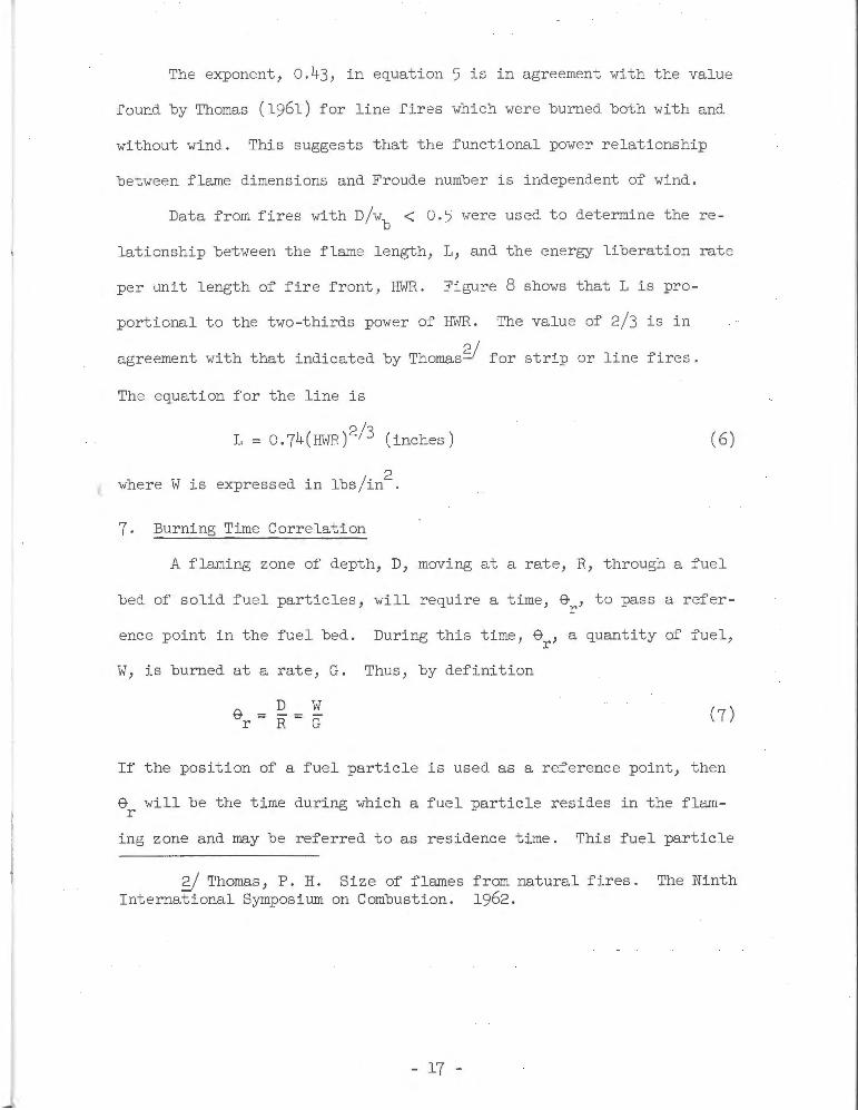
The exponent, 0.43, in equation 5 is in agreement with the value
found by Thomas (1961) for line fires which were burned both with and
without wind. This suggests that the functional power relationship
between flame dimensions and Froude number is independent of wind .
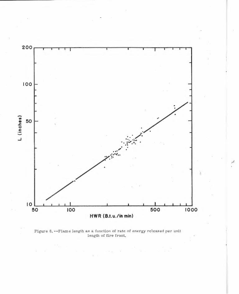
Data from fires with D/wb < 0.5 were used to determine the re
lationship between the flame length, L, and the energy liberation rate
per unit length of fire front, HWR. Figure 8 shows that L is pro
portional to the two-thirds power of HWR. The value of 2/3 is in
agreement with that indicated by Thomas~/ for strip or line fires.
The equation for the line is
L; 0.74(HWR)2/ 3 (inches)
where W is expressed in lbs/in2
.
7. Burning Time Correlation
(6)
A flaming zone of depth, D, moving at a rate, R, through a fuel
bed of solid fuel particles , will require a time, & , to pass a referr
ence point in the fuel bed.
W, is burned at a rate, G.
During this time, & , a quantity of fuel, r
Thus, by definition
(7)
If the position of a fuel particle is used as a reference point, then
& will be the time during which a fuel particle resides in the flamr
ing zone and may be referred to as r esidence time. This fuel particle
2/ Thomas, P. H. Size of flames from natural fires. The Ninth Internati onal Symposium on Combustion. 1962 .
- 17 -
100
-: 50 .6: u c -
..J
100
. . .;. .. , ••. ·=·· . ;·".... . ..
,: .· ... • •.•tl •• .. :·
HWR (B.t.u./in min) 500
Figure 8. --Flame length as a function of rate of energy released per unit length of fire front.
1000
i
of initial thickness, d0
, when ignited, is at the front of the flaming
zone and is surrounded by a gas at temperature, t . The gas is emitted g
by the burning particles spaced at regular intervals from each other.
At i gniti on, the center of the particle is at temperature, t , and its 0
temperature increases with time until the particle reaches the rear of
the flaming zone. It is assumed that when the particle arrives at the
rear of the flaming zone all of its volatiles are released and its
center reaches the same temperature as that of the surrounding gas.
It is also assumed that at the burning surface the mass transfer of
the volatiles from the burning particle is proportional to the heat
transfer by conduction into the particle. This presupposes that the
mass diffusivity is proportional to the thermal diffusivity. The heat
flow to the burning particle from the neighboring burning particles is
proportional to hd /k . Since the temperature of the surrounding gas 0 g
is assumed to be constant, it follows then that the ratio h/k is g
effectively constant. The temperature, t , of the gas will depend on g
its heat capacity and the amount of heat transferred to it by the burn-
ing particles of the combustion zone less the losses by convection to
the atmosphere. For steady- state conditions, it is assumed that the
gas temperature, t , and density, p , remain constant and have the g g
values of 1650° F. and 0.019 lb/ft3, respectively (Kawagoe, 1958).
Consider a flaming zone moving through a fuel bed of height, ~'
width, wb, and composed of fuel particles with initial thickness, d0
,
moisture content, Mf, and density, pf. At time, G, after the particle
enters the flaming zone, the temperature, t, at the center of a
particle may be determined by an equation which expresses the fuel and
- 19 -
fuel bed parameters and the mass and energy transfer rates in terms
of dimensionless groups. The equation is written as
t - t 0
t - t g 0
v ~ v J
f
4~ J2_) d J d
0 0
The first two dimensionless groups on the right side of
equation 8 are, respectively, Fourier number and the length and
depth of flame ratioj the latter is a function of Froude number as
presented in the preceding section. Fourier number describes the
(8)
heat transfer by conduction into a solid body from its surface and in
this analysis it is assumed to be proportional to mass transfer
(Spalding, 1955). Froude number, in this case, represents the natural
convective heat and mass transfer from a source to the atmosphere . The
third dimensionless group, k /hd , is the reciprocal of Nusselt number, g 0
which describes the heat transfer between the surface of the particle
and the surrounding gas . If k /h is assumed to remain constant during g
the burning of a part i cle of initial s i ze, d , then t he dimensionless 0
group k h/d may be considered as an independent parameter . The reg 0
maining six groups of equation 8 are ratios involving fuel and fuel
bed parameters .
It follows that when B = B , then t - t = t - t and equation 8 r o g o
may be written as
(9)
,I
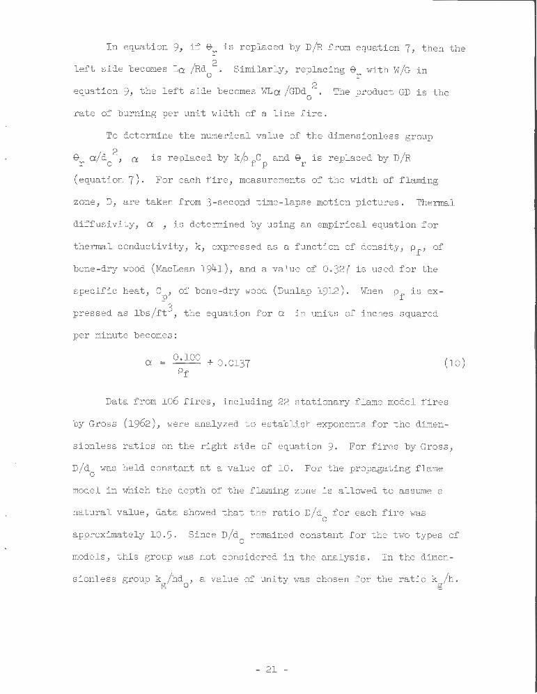
In equation 9, if e is replaced by D/R from equation 7, then the r 2
left side becomes La /Rd . Similarly, replacing 9 with W/G in o r
equation 9, the left side becomes WLa /GDd 2
. The product GD is the 0
rate of burning per unit width of a line fire .
To determine the numerical value of the dimensionless group
e a/d 2
, a is replaced by k/p fc and e is replaced by D/R r o p r
(equation 7). For each fire , measurements of the width of flaming
zone, D, are taken from 3- second time-lapse motion pictures. Thermal
diffusivity, a , is determined by using an empirical equation for
thermal conductivity, k, expressed as a function of density, pf' of
bone-dry wood (MacLean 1941), and a value of 0 .327 is used for the
specific heat, Cp' of bone -dry wood (Dunlap 1912). When pf is ex
pressed as lbs/ft3, the equation for a in units of inches squared
per minute becomes:
a = O. lOO + 0.0137 Pf
(10)
Data from 106 fires, including 22 stationary flame model fires
by Gross (1962), were analyzed to establish exponents for the dimen-
sionless ratios on the right side of equation 9 . For fires by Gross,
D/d was held constant at a value of 10. For the propagating flame 0
model in which the depth of the flaming zone is a llowed to assume a
natural value, data
approximately 10.5.
showed that the ratio D/d for each fire was 0
Since D/d remained constant for the two types of 0
models, this group was not considered in the analysis. In the dimen-
sionless group k /hd , a value of unity was chosen for the ratio k /h . g 0 g
- 21 -
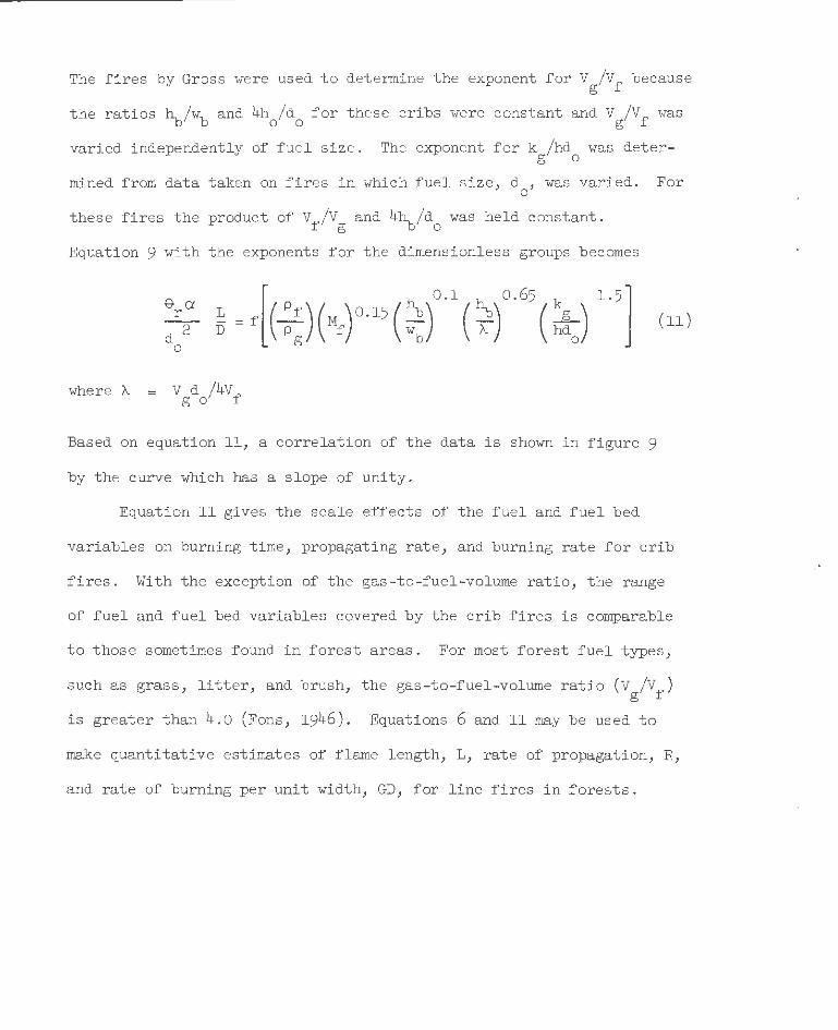
The fires by Gross were used to determine the exponent for Vg/Vf because
the ratios ~/wb and 4h0/d
0 for these cribs were
varied independently of fuel size. The exponent
constant and Vg/Vf was
for k /hd was deterg 0
mined from data taken on fires in which fuel size, d , was varied . For 0
these f ires the product of Vf/Vg and 4~/d0 was held constant .
Equation 9 with the exponents for the dimensionless groups becomes
where ~ = V d /4Vf g 0
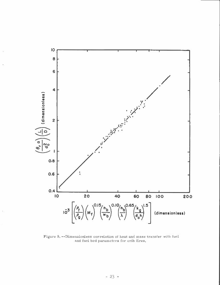
Based on equation 11, a correlation of the data is shown in figure 9
by the curve which has a slope of unity.
Equation ll gives the scale effects of the fuel and fuel bed
variabl es on burning time , propagating rate, and burning rate for crib
f i res. With the excepti on of the gas -to -fuel-volume ratio, the range
of fue l and fuel bed variables covered by the crib f ires is comparable
t o those sometimes found in forest areas. For most forest fuel types,
such as grass, l i tter, and brush, the gas-to-fuel-volume ratio (Vg/Vf)
is greater than 4 .0 (Fons, 1946). Equations 6 and ll may be used to
make quantitative estimat es of flame length, L, rate of propagation, R,
and rate of burning per unit width, GD, for line fires in f orests.
IOr-------~~------~~---,--~---r--------~
8
6
4 • • • c 0
• c • e 'U 2 -
.......-:--.... ..Jio ~
.......-:--.... a.._INo
Cb 'U
~
o.a
0.6
20
., . . . v.·· .. · • •
. /··. .. ..
/ /
... ( '•
I ·'I'' . .• .:~' ...
. ·Y "' /"
• •
40 60 80 100
Figure 9. --Dimensionless correlation of heat and mass transfer with fuel and fuel bed parameters for crib fires.
- 23 -
200
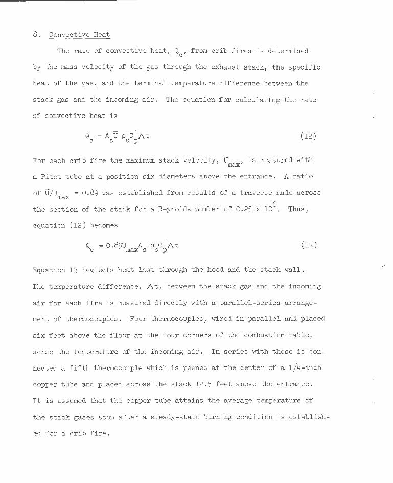
8. Convective Heat
The rate of convective heat, Q , from crib fires is determined c
by the mass velocity of the gas through the exhaust stack, the specific
heat of the gas, and the terminal temperature difference between the
stack gas and the incoming air. The equation for calculating the rate
of convective heat is
t
Q =AUpC.[lt c s s p
( 12)
For each crib fire the maximum stack velocity, U , is measured with max
a Pitot tube at a position six diameters above the entrance. A ratio
of U/U = 0.89 was established from results of a traverse made across max
6 the section of the stack for a Reynolds number of 0.25 x 10 . Thus,
equation (12) becomes
t
Q = 0. 89U A p C .6 t c maxs sp (13)
Equation 13 neglects heat l ost through the hood and the stack wall.
The temperature difference, .6t, between the stack gas and the incoming
air for each fire is measured directly with a parallel-series arrange-
ment of thermocouples. Four thermocouples, wired in parallel and placed
six feet above the floor at the four corners of the combustion table,
sense the temperature of the incoming air. In series with these is con-
nected a fifth thermocouple which is peened at the center of a 1/4-inch
copper tube and placed across the stack 12.5 feet above the entrance .
It is assumed that the copper tube attains the average temperature of
the stack gases soon after a steady-state burning condition is establish-
ed for a crib fire .

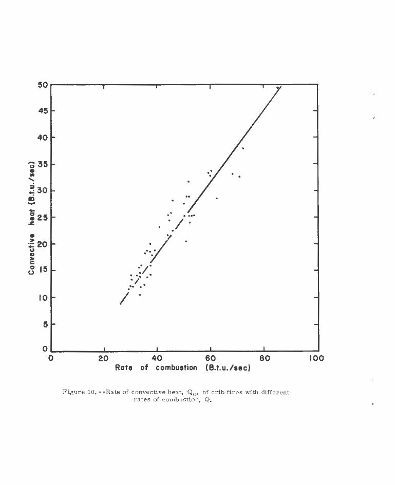
Figure 10 shows that the rate of convective heat, Q , calculated c
by equation (13), is proportional to the rate of combustion, Q. The
rate of combustion is determined by the following equation:
Q : HGwblo
8640
9. Radiative Heat
(Btu/sec) (14)
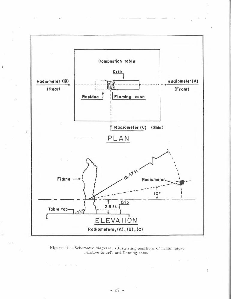
a. Irradiance.--The irradiance of the crib fires was measured by
directional thermopile radiometers at three different positions
(fig. 11) . The radiometer distance of 18.57 feet from the flaming
zone was more than adequate to permit the hot-junction receiver strip
to see the combined area of the burning zone within the crib and the
flaming zone above the crib. Detailed description of the directional
radiometer is given in reference (Gier and Boelter, 1941, pp. 1284-1292).
Briefly, the radiometer consists of a 150-junction, silver-constantan
thermopile mounted in the rear of a cylindrical metal housing. A rear
plate with a narrow slot allows radiation entering the front opening
of the radiometer to impinge on the hot-junction receiver strip, while
shielding the cold- junction strip . The output of the thermopile is
linear. A calibration factor, K, in Btu/ft~r per millivolt output is
furnished for each instrument by the manufacturer .
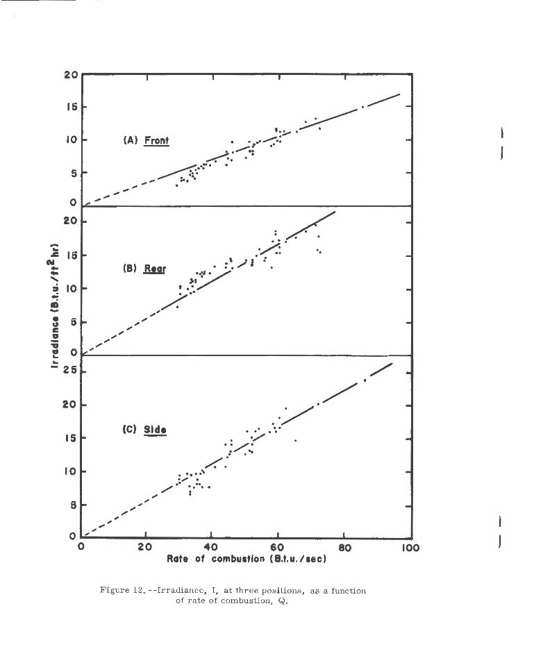
Tables 8 and 9 in Appendix A give irradiance measured at three
positions (front, rear, and side of fire) for 57 fires. Figure 12
shows irradiance, I, as a function of rate of combustion, Q. The re-
sults shown in figure 12 indicate that the irradiance at the side and
rear of the crib fires are approximately equal . The results also show
that the irradiance at the front of the fire is about 60 percent of the
- 25 -
45
40
'()35 • • ' . ~30 CD -• > :;: 20 u ., > c 0 15 u
10
5
• • . . . ... . I . •
··I I •
o~ ________ ._ ________ ._ ____________________________ _ 0 20 40 60 80
Rate of combustion (B.t.u./sec)
F igure 10, --Rate of convective heat, Qc, of crib fires with different rates of combustio n, Q.
100
,I
f
Combustion table
Crib ---, Radiometer (B)
(Rear) ------ {-~=~-~i- ----- --+-- ----- -
FICime-
I
Residue f :f Flaming zone I
f Radiometer (C) (Side)
PLAN
------
Table top-, 4:~:
ELEVATION Radiometers, (A), (B), (C)
Radiometer (A)
(Front)
F i gure 1 1. - -Schemati c di agram, i llustrati ng positions of radiomete rs rel ative to c r ib and flaming zone.
- 27 -
20 I I J I
15
10
• -~-~ '. :....-- .
ioo (A) Front . . .. ...,..........: -I •"
~· ......... ": .. . 5
0
~ .... . ~
.. -. . "' ... "' .... . ., .... ., -"' .,
20
-.. .c 15 ~ ~ .. ..... .
10 ~
.: CD -• 5 " c II -
~ -./ . . . -~·
~ .. .. -·',II.:
(8) .Bur . . . . y ,. .
~ • •• .. /. .. ,., .. .,,. -,. ,.,. ,. ,
II 0 ~
"' ~.;o'
~
-25 ~ / -20 ~
15 ~
10 ~
6 ~
0 0
, ,
•
. / .·/
(C) Slde . .. ··/ .. . . . . /.. . .. . . /.: ........ .,. . .. ..
/ . . . . ,. I
""" ,. , ,
, .... ,
I I I I
20 40 60 80 Rate of combustion ( B.t.u. /sec)
Figure 12. --Irradiance, I, at three positions, as a function of rate of combustion, Q.
-
---100
' ,
J
J
,,
' ,
l ,
irradiance measured at the side or rear. The decrease in irradiance
at the front of the fire may be accounted for by the fact that the
burning zone within the crib is shielded from the radiometer by the
unburned portion of the crib, (see figure 11, radiometer position (A)).
This suggests that the burning zone within the crib contributes about
40 percent of the irradiance toward the unburned fuel.
b. Rate of Radiative Heat.--Measurements of the irradiance were
made at several points for determining the rate of radiative heat.
These measurements were made for fires in cribs of different species
of wood, (see table 5). For these fires the three radiometers at
positions (A), (B), and (C) in figure ll were mounted on carriages
which could be moved along a curved standard to various elevation
0 0 ) angles, ranging from -15 to +50 , (Fons et al., 1959 . The radius
of curvature for the standard was 14 feet with the origin at a point
in the flame 2 feet above the base of the fuel bed. The horizontal or
zero position of the radiometer angle, therefore, corresponds to the
base of a hemisphere with a radius of 14 feet. Readings f or each radi
ometer were taken at angles of 0°, 10°, 20°, 30°, 40°, and 50° during
the steady-state burning period of a fire. Irradiance data for each
of the three positions were plotted against elevation angles from 0°
to 50°. The curves drawn through the points were extended to -10° and
90° to approximate the irradiance below 0° and above 50°. This method
of approximating the irradiance above 50° should not seriously affect
the final result because the surface area of the hemisphere from 50°
to the zenith or 90° is only 15 percent of the surface area used in
calculating the total radiant energy. The cutoff angl e imposed by
- 29 -
the combustion table on the radio~eters was about go below the hori
zontal, so radiant energy from _go to - 90° was not included in the
integra~ion procedure. It is assumed that the radiant energy inter-
cepted by the top of the combustion table is transferred to the
entrained air as convective heat.
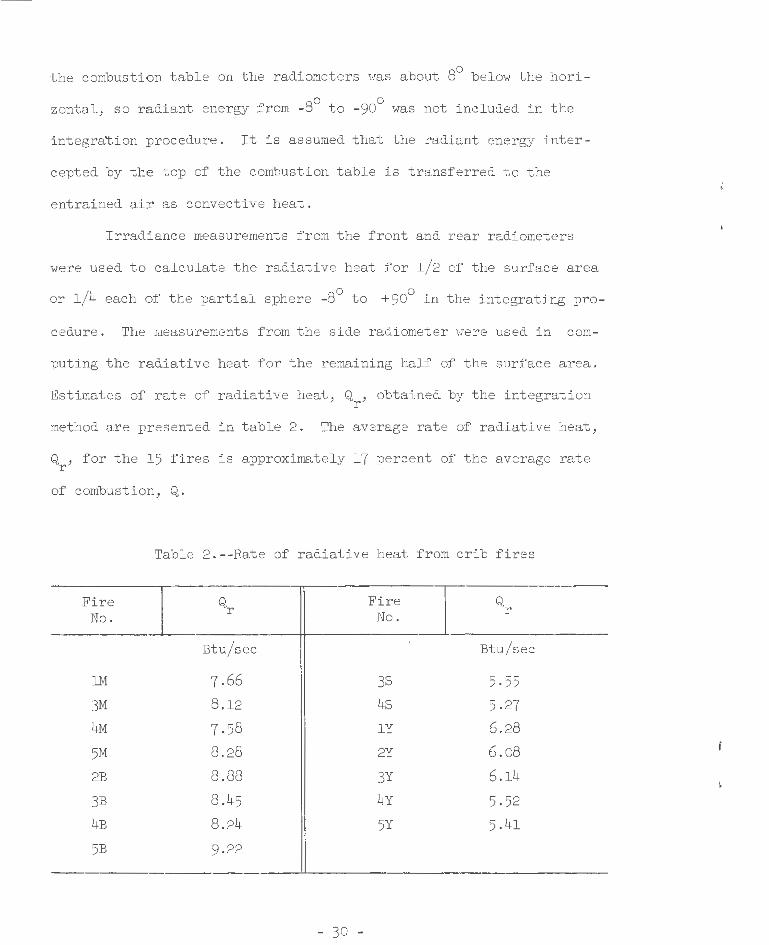
Irradiance measurements f rom t he front and rear radiometers
were used to calcul ate t he radiative heat for l/2 of the surface area
or l/4 each of the partial sphere _go to + 90° in the integrating pro -
cedure . The measurements from the side radiometer were used in com-
puting the radiative heat for the remaining half of the surface area .
Estimates of rate of radiative heat, Q , obtained by the integration r
method are presented in table 2 . The average rate of radiative heat,
Q , for the 15 fires is approximately 17 percent of the average rate r
of combustion, Q.
Table 2.--Rate of radiative heat from crib fires
Fire No.
1M
3M 4M
5M 2B
3B
4B
5B
Qr
Btu/sec
7.66
g .l2
7.5g
g.2g
g.gg
g.45
g .24
9 .22
- 30 -
Fire I Qr No.
Btu/sec
38 5·55
4s 5.27
lY 6.2g
2Y 6.og
3Y 6 .14
4Y 5 . 52
5Y 5 .41
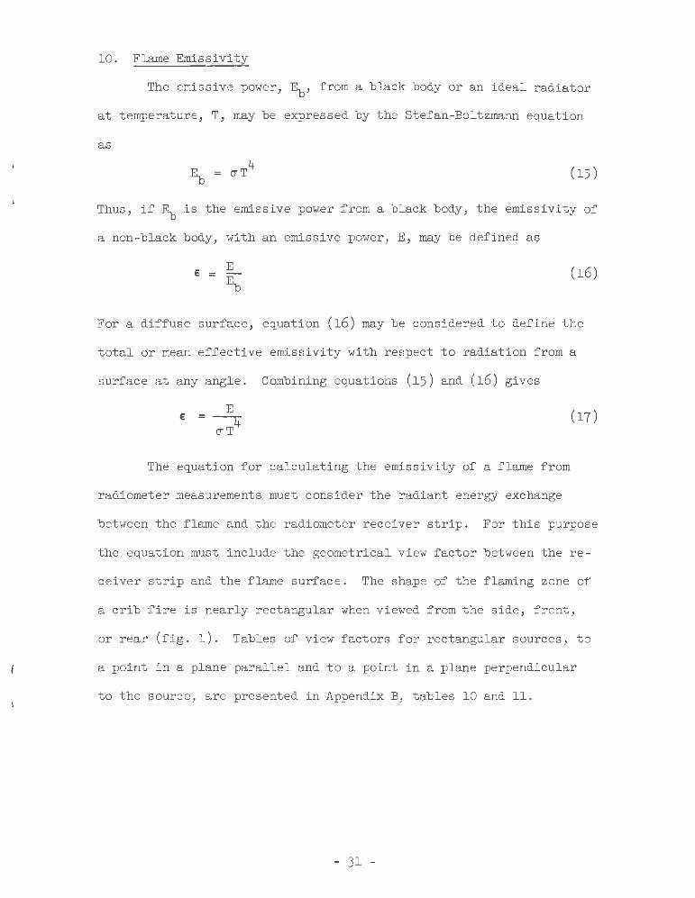
10. Flame Emissivity
The emissive power, Eb, from a black body or an ideal radiator
at temperature, T, may be expressed by the Stefan-Boltzmann equation
as
4 E = CJT
b ( 15)
Thus, if ~ is the emissive power from a black body, the emissivity of
a non-black body, with an emissive power, E, may be defined as
(16)
For a diffuse surface, equation (16) may be considered to define the
total or mean effective emissivity with respect to radiation from a
surface at any angle. Combining equations (15) and (16) gives
E € = (17) ~
The equation for calculating the emissivity of a flame from
radiometer measurements must consider the radiant energy exchange
between the flame and the radiometer receiver strip. For this purpose
the equation must include the geometrical view factor between the re-
ceiver strip and the flame surface. The shape of the flaming zone of
a crib fire is nearly rectangular when viewed from the side, front,
or rear (fig. 1). Tables of view factors for rectangular sources, to
a point in a plane parallel and to a point in a plane perpendicular
to the source, are presented in Appendix B, tables 10 and 11.
- 31 -
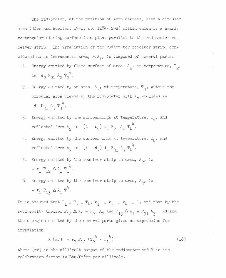
The radiometer, at the position of zero degrees, sees a circular
area (Gier and Boelter, 1941, pp. 1284-1292) within which is a nearly
rectangular flaming surface in a plane parallel to the radiometer re-
ceiver strip. The irradiation of the radiometer receiver strip, con-
sidered as an incremental area, ~A1, is composed of several parts;
l. Energy emitted by flame surface of area, A2, at temperature, T2,
. 4 lS €2 F 21 A2 T 2 •
2. Energy emitted by an area, A3
, at temperature, T3
, within the
circular area viewed by the radiometer with A2
excluded is
€3 F 31 A3 T 3 4
.
3. Energy emitted by the surroundings at temperature, T4, and
4 reflected from A2 is (l - £2 ) £4 F21 A2 T4
4. Energy emitted by the surroundings at temperature, T4, and
4 reflected from A
3 is (l - £
3) £ 4 F
31.A
3 T4
5. Energy emitted by the receiver strip to area, A2 , is
4 - £1 F 12 ~ Al T l .
6. Energy emitted by the receiver strip to area, A3
, is
4 - €1 F 13 ~ Al T .
It is assumed that T1 = T3
= T4, £ 1 = £3
= £4 = l, and that by the
reciprocity theorem F12 ~A1 = F 21 A2 and F13 ~A1 = F
31 A
3. Adding
the energies emitted by the several parts gives an expression for
irradi ation
K (mv)
where (mv) is the millivolt output of the radiometer and K is its
calibration factor in Btu/ft2hr per millivolt .
(18)
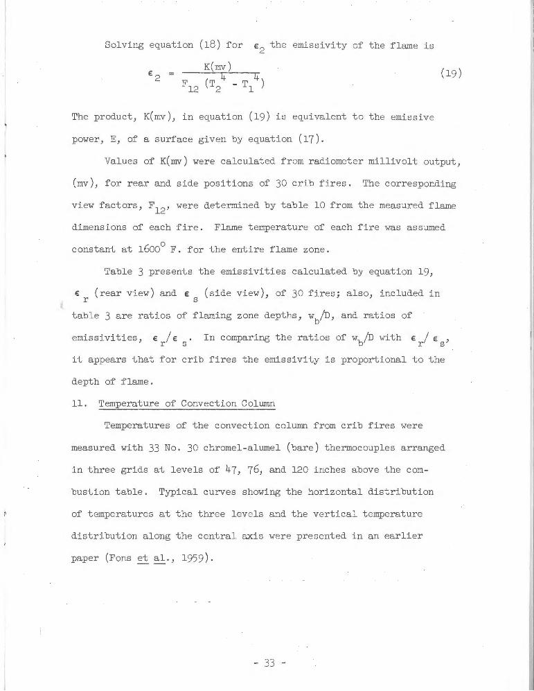
Solving equation (18) for e2 the emissivity of the flame is
K(mv) (19)
The product, K(mv), in equation (19) is equivalent to the emissive
power, E, of a surface given by equation (17).
Values of K(mv) were calculated from radiometer millivolt output,
(mv), for rear and side positions of 30 crib fires. The corresponding
view factors, F12, were determined by table 10 from the measured flame
dimensions of each fire. Flame temperature of each fire was assumed
0 constant at 1600 F. for the entire flame zone.
Table 3 presents the emissivities calculated by equation 19,
€ (rear view) and € (side view), of 30 fires; also, included in r s
table 3 are ratios of flaming zone depths, wbiD, and ratios of
emissivities, e I e . r s In comparing the ratios of wbiD with € I e ,
r s
it appears that for crib fires the emissivity is proportional to the
depth of flame.
ll. Temperature of Convection Column
Temperatures of the convection column from crib fires were
measured with 33 No. 30 chromel-alumel (bare) thermocouples arranged
in three grids at levels of 47, 76, and 120 inches above the com-
bustion table. Typical curves showing the horizontal distribution
of temperatures at the three levels and the vertical temperature
distribution along the central axis were presented in an earlier
paper (Fons et al., 1959 ).
- 33 -
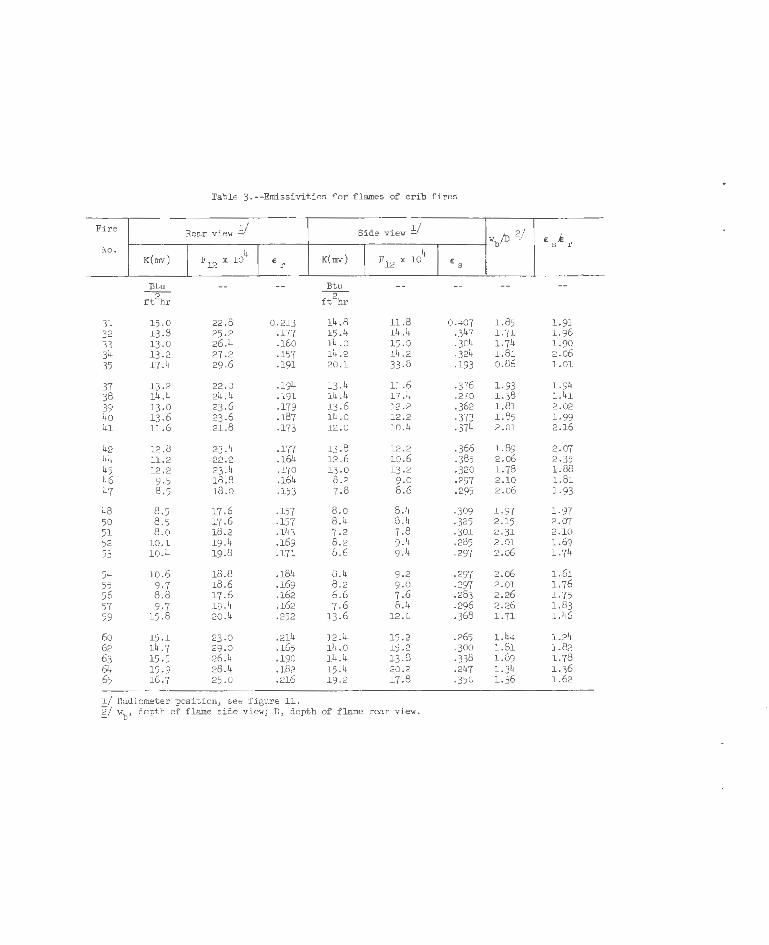
Table 3.--Emissivities for flames of crib fires
Fire Rear vie;, !::/ Side vie;, Y "/D g/ £ s,k r No.
I Fl2 X 104 I I I b
4 K(mv) £ r K(mv) F12 x 10 £ s
Btu Btu
ft~r ft2hr
31 15.0 22 .8 0.213 14.8 11 .8 0.407 1.85 1.91 32 13.8 25.2 .177 15 .4 14 .4 .347 1.71 1.96 33 13.0 26.4 . l6o 14 .0 15 .0 .3o4 1.74 1.90 34 13.2 27.2 .157 14.2 14.2 .324 1.81 2 .06 35 17.4 29 .6 .191 20 .1 33 .8 .193 0.86 l. Ol
37 13.2 22 .0 .194 13 .4 11.6 ·376 1.93 1.94 38 14.4 24.4 .191 14 .4 17.4 .270 1.38 1.41 39 13 .0 23.6 .179 13 .6 12 .2 .362 1.81 2.02 40 13.6 23 .6 .187 14 .0 12.2 -373 1.85 1.99 41 11.6 21.8 .173 12 .0 10.4 ·374 2.01 2.16
42 12 .8 23.4 .177 13 .8 12 .2 .366 1.89 2.07 44 11.2 22.2 .164 12 .6 10.6 .385 2.o6 2.35 45 12.2 23 .4 .170 13 .0 13 .2 .320 1.78 1.88 46 9 ·5 18 .8 .164 8 .2 9 .0 .297 2.10 1.81 47 8 .5 18 .0 .153 7.8 8.6 .295 2.06 1.93
48 8.5 17.6 .157 8 .0 8 .4 ·309 1. 97 1.97 50 8.5 17.6 .157 8 .4 8 .4 ·325 2.15 2.07 ,I 51 8.0 18 .2 .143 7 -2 7 .8 ·301 2.31 2.10 52 10.1 19.4 .169 8 .2 9 .4 .285 2.01 1.69 53 10.4 19.8 .171 8.6 9.4 .297 2.o6 1.74
54 10.6 18.8 .184 8 .4 9 ·2 .297 2.o6 1.61 55 9·7 18 .6 .169 8 .2 9 -0 .297 2.01 1.76 56 8.8 17.6 .162 6.6 7 .6 .283 2.26 l. 75 57 9·7 19 .4 .162 7 .6 8 .4 .296 2 .26 1.83 59 15.8 20 .4 .252 13 .6 12 .0 .368 1.71 1.46
6o 15.1 23.0 .214 12.4 15 .2 .265 1.44 1.24 62 14.7 29 .0 .165 14 .0 15 .2 .300 1.81 1.82 63 15.5 26 .4 .190 14 .4 13 .8 -338 1.89 1.78 64 15.9 28.4 .182 15.4 20 .2 .247 1.34 1 .36 65 16.7 25.0 .216 19.2 17.8 -350 1.36 1.62
!/ Radiometer position, see figure 11. gj "b' depth of flame side vie;,; D, depth of flame rear vie;, .
The natura l convection movement of the heated column above fires
is responsible for the air entrainment into the column. To gain a fun-
damental understanding of the convection zone of a fire burning in a
free atmosphere, Sce sa and Sauer (1954) and Yih (1953, pp. 117-133)
made theoretical analyses of the transport processes for point and
line heat sources based on heat transfer and fluid flow theories. Lee
and Emmons (1961) made a theoretical analysis and an experimental study
of the convection above a line fire with a channel burner us ing the
liquid fuels acetone and methyl alcohol. Yih used Bunsen burners to
study convection above a point source.
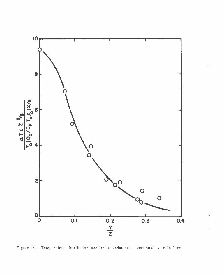
The equation, giving temperature distribution within a turbulent
column above a point source (Scesa and Sauer, 1954), was rearranged
into a functional relationship between dimensionless height and dimen-
sionless temperature rise as foll ows:
y z;= ¢ L.J. g
[
A T z5/3 ]
(Q / c To Po )2/3 To c p (20)
The temperature data of the convection column from 20 fires in
cribs 5.5 inches high and 9.25 inches wide were correlated, using the
functional relationship given by equation 20. Since these crib fires
are finite sources, l /2 foot was added to the hei ght to adjust values
of Z to a vertical distance from a virtual point source. Figure 13
shows the relationship of the two dimensionless groups which character-
izes the temperature field of the convection columns resulting from
these wood crib fires. The correlation of the two dimensionless groups
for the crib fires agrees reasonably well with results obtained by
Yih (1953, pp. 117-133 ).
- 35 -
~ ., N 0 ~
<l
10
' N -6 Q..o .,_o 0.
u ' 0 CJ -.,_o 4
2
0
0
0
oO
""'0 ° 0 0~
0~--------~--------~----------------~ 0 0.1 0.2 y -z
0.3 0.4
Figure 13, --Temperature dis t r ibution function for turbul ent convecti on a bove c r ib fi r es.
II
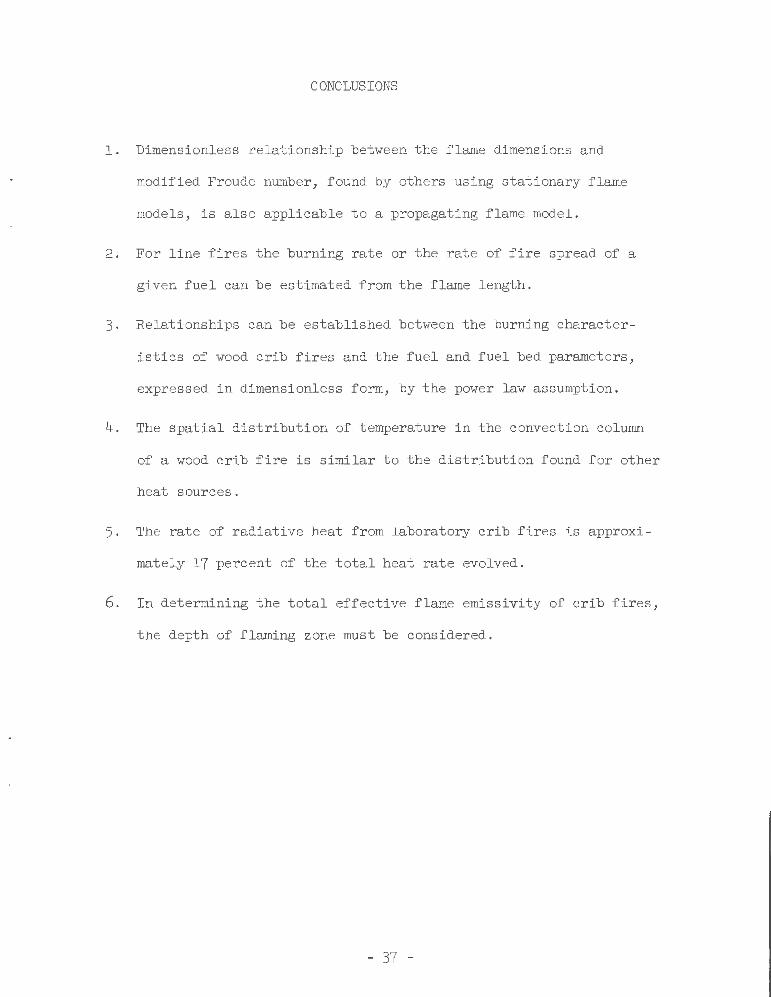
CONCLUSIONS
1 . Dimensionless relationship between the flame dimensions and
modified Froude number, found by others using stationary flame
models, is also applicable to a propagating flame model.
2. For line fires the burning rate or the rate of fire spread of a
given fuel can be estimated from the flame length .
3. Relationships can be established between the burning character
istics of wood crib fires and the fuel and fuel bed parameters,
expressed in dimensionless form, by the power law assumption.
4. The spatial distribution of temperature in the convection column
of a wood crib fire is similar to the distribution found for other
heat sources.
5. The rate of radiative heat from laboratory crib fires is approxi
mately 17 percent of the total heat rate evolved.
6. In determining the total effective flame emissivity of crib fires,
the depth of flaming zone must be considered.
- 37 -
PLANS FOR CONTINUATION
A proposal for the continuation of Project Fire Model was sub
mitted on November 17, 1961, to the Bureau of Standards for consider
ation. The proposal was approved on February 28, 1962, for a period
ending June 30, 1963.
A brief description of the research work proposed to be undertaken
follows:
l. To learn the effect of fuel size upon certain dependent variables
associated with free-burning fire . The effect of fuel size on rate
of spread through white fir wood cribs has been obtained for a
range of stick sizes, from l/4 to l-l/4 inches square (see page 34,
Summary Report, May 31, 1960). These tests were made with density
and moisture content of the wood constant, averaging 0.385 and 10.4
percent, respectively. It is proposed to conduct additional tests
to include higher and lower densities and moisture contents. Data
from such tests should confirm whether or not residence time scales
to the three-halves power of fuel size regardless of fuel moisture
or density.
2. To l earn the effect of particle spacing in the fuel bed on fire
characteristics. Earlier work on fire spread with beds of natural
fuels indicated that rate of spread increased as the ratio of voids
to the fuel surface area in the fuel bed increased.
The spacing of sticks making up the cribs tested on the project
thus far has been kept at a constant value of l-l/4 inches on the
horizontal plane; on the vertical plane the spacing has been equal
to the thickness of the sticks. It is proposed to test cribs of
l/2-inch square sticks of white fir with spacing varied from l/2 to
approximately 3 inches. Present method of crib construction will
be modified to obtain equal spacing in the vertical and horizontal
plane regardless of stick sizes.
3. To relate the properties of free-burning fire in wood-crib fuel
beds to independent variables affecting the fire. Analysis of the
phenomenon of combustion of beds of solid fuels will be continued
to explain such behavior aspects as rate of spread, partition of
energy, and convection column characteristics. The ultimate
objective of these analyses will be to develop through theory and
from experimental data obtained from model fires scaling laws for
prediction of the behavior and properties of full-scale free
burning fires.
- 39 -
Symbol
A s
c
c p
c p
d 0
D
E
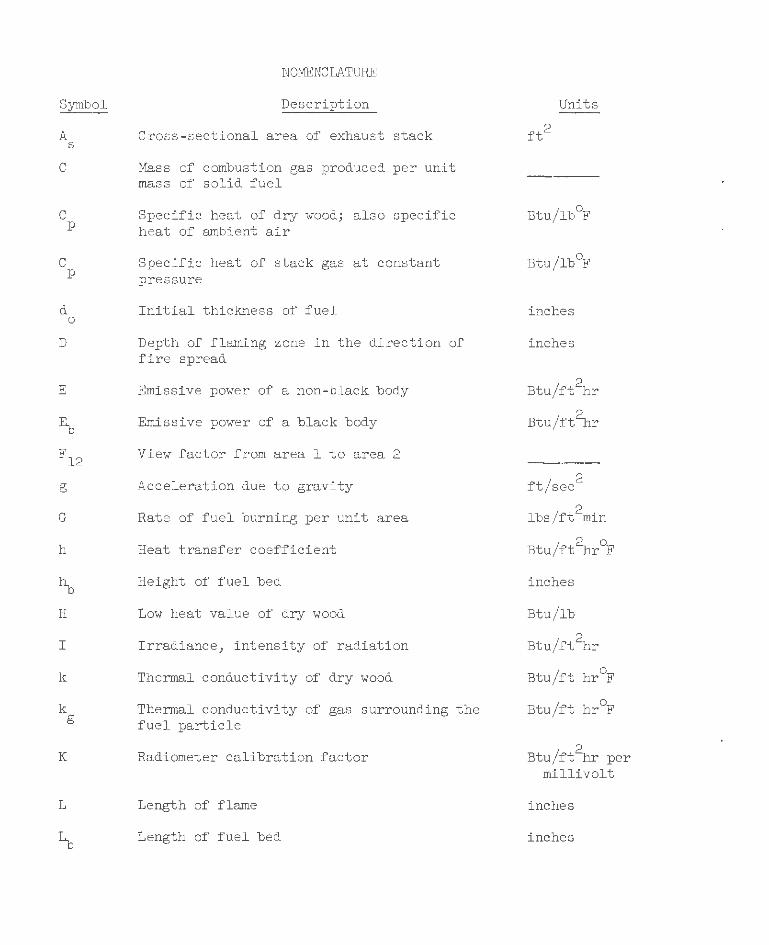
NOMENCLATURE
Description
Cross-sectional area of exhaust stack
Mass of combustion gas produced per unit mass of solid fuel
Specific heat of dry wood; also specific heat of ambient air
Specific heat of stack gas at constant pressure
Initial thickness of fuel
Depth of flaming zone in the direction of fire spread
Emissive power of a non-black body
Emissive power of a black body
F12 View factor from areal to area 2
g
G
h
H
I
k
k g
K
L
Acceleration due to gravity
Rate of fuel burning per unit area
Heat transfer coefficient
Height of fuel bed
Low heat value of dry wood
Irradiance, intensity of radiation
Thermal conductivity of dry wood
Thermal conductivity of gas surrounding the fuel particle
Radiometer calibration factor
Length of flame
Length of fuel bed
Units
Btu/lb°F
Btu/lb°F
inches
inches
2 Btu/ft hr
Btu/ft~r
ft/sec2
lbs/ft2min
Btu/ft~r°F
inches
Btu/lb
Btu/ft~r
Btu/ft hr°F
Btu/ft hr°F
Btu/ft~r per millivolt
inches
inches
f
:'I
1
j
m
t
t g
t 0
t s
T
T 0
u max
v
w
y
z
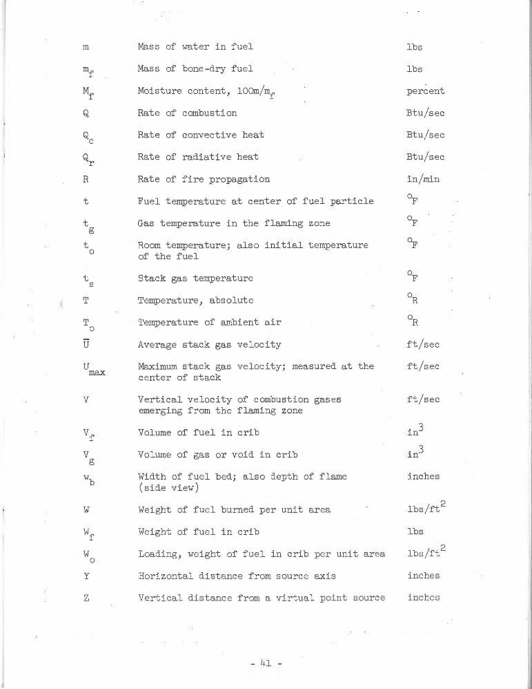
Mass of water in fuel
Mass of bone-dry fuel
Moisture content, lOOm/mf
Rate of combustion
Rate of convective heat
Rat e of radiative heat
Rate of fire propagation
Fuel temperature at center of fuel particle
Gas temperature in the flaming zone
Room temperature; also initial temperature of the fuel
Stack gas temperature
Temperature, absolute
Temperature of ambient air
Average stack gas velocity
Maximum stack gas velocity; measured at the center of stack
Vertical velocity of combustion gases emerging from the flaming zone
Volume of fuel in crib
Volume of gas or void in crib
Width of fuel bed; also depth of flame (side view)
Weight of fuel burned per unit area
Weight of fuel in crib
Loading, weight of fuel in crib per unit area
Horizontal distance from source axis
Vertical distance from a virtual point source
- 41 -
lbs
lbs
percent
Btu/sec
Btu/sec
Btu/sec
ft/sec
ft/sec
ft/sec
inches
lbs
lbs/ft2
inches
inches
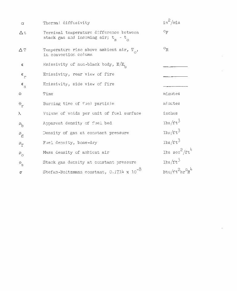
a:
~t
~T
Thermal diffusivity
Terminal temperature difference between stack gas and incoming air; t - t
s 0
Temperature rise above ambient air, T , in convection column °
€ Emissivity of non-black body, E/Eb
€ Emissivity, rear view of fire r
€ Emissivity, side view of fire s
e r
Time
Burning time of fuel particle
Volume of voids per unit of fuel surface
Apparent density of fuel bed
Density of gas at constant pressure
Fuel density, bone-dry
Mass density of ambient air
Stack gas density at constant pressure
4 -8 Stefan-Boltzmann constant, 0.171 x 10
. 2/ . ln nun
minutes
minutes
inches
lbs/ft3
lbs/ft3
lbs/ft3
2 4 lbs sec /ft
lbs/ft3
Btu/ft2hr
0R4
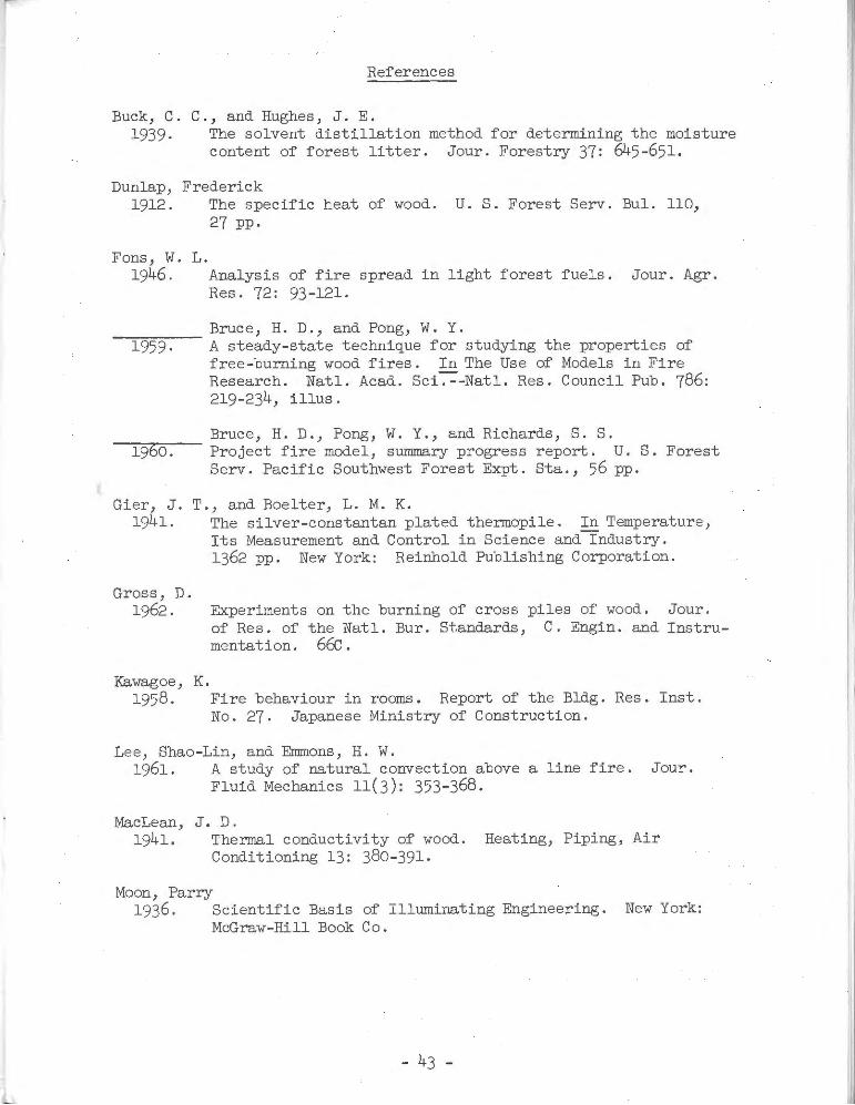
References
Buck, C. C., and Hughes, J. E. 1939. The solvent distillation method for determining the moisture
content of forest litter. Jour. Forestry 37: 645-651.
Dunlap, Frederick 1912. The specific heat of wood. U. S. Forest Serv. Bul. 110,
27 pp.
Fans, W. L. 1946. Analysis of fire spread in light forest fuels. Jour. Agr.
Res. 72: 93-121.
Bruce, H. D., and Pong, W. Y. --..,-----1959· A steady-state technique for studying the properties of free-burning wood fires. In The Use of Models in Fire Research. Natl. Acad. Sci~-Natl. Res. Council Pub. 786: 219-234, illus.
Bruce, H. D., Pong, W. Y., and Richards, S. S. --=-l-=9""76-=o-.-- Project fire model, summary progress report . U. S. Forest
Serv. Pacific Southwest Forest Expt. Sta., 56 pp.
Gier, J. 1941.
T., and Boelter, L. M. K.
Gross, D. 1962.
Kawagoe, K.
The silver-constantan plated thermopile. In Temperature, Its Measurement and Control in Science and-rndustry. 1362 pp. New York: Reinhold Publishing Corporation.
Experiments on the burning of cross piles of wood. Jour . of Res. of the Natl. Bur. Standards, C. Engin . and Instrumentation. 6tc.
1958. Fire behaviour in rooms . Report of the Bldg. Res . Inst. No . 27. Japanese Ministry of Construction.
Lee, Shao-Lin, and Emmons, H. W. 1961. A study of natural convection above a line fire. Jour.
Fluid Mechanics 11(3): 353-368.
MacLean, J. D. 1941. Thermal conductivity of wood. Heating, Piping, Air
Conditioning 13: 380-391.
Moon, Parry 1936 . Scientific Basis of Illuminating Engineering. New York:
McGraw-Hill Book Co.
- 43 -
Scesa, S., and Sauer, F. M. 1954. Possible effects of free convection on fire behavior-
laminar and turbulent line and point sources of heat. U. S. Forest Serv. Calif. Forest and Range Expt. Sta. Tech. Paper 8, 47 pp.
Spalding, D. B. 1955. Some fundamentals of combustion. In Gas Turbine Series 2.
250 pp. London: Butterworths Scientific Publications.
-Thomas, P. H. 1961. Research on fires using models. The Inst. Fire Engin.
Quart. XXI: 197-219.
Webster, C. T., and Raftery, M. M. --71~97671-.--- Some experiments on buoyant diffusion flames. Combustion
and Flames 5: 359-367.
Wise, Louis E., and Jahn, Edwin C. 1952. Wood Chemistry. 2 v, 1343 pp. New York: Reinhold
Publishing Corporation.
Yih, Chia-Shun 1953. Free convection due to boundary sources. In First Symposium
on the Use of Models in Geophysical Fluid-nymamics. 162 pp. Supt. of Documents, U. S. Government Printing Office, Washington, D. C.
, I
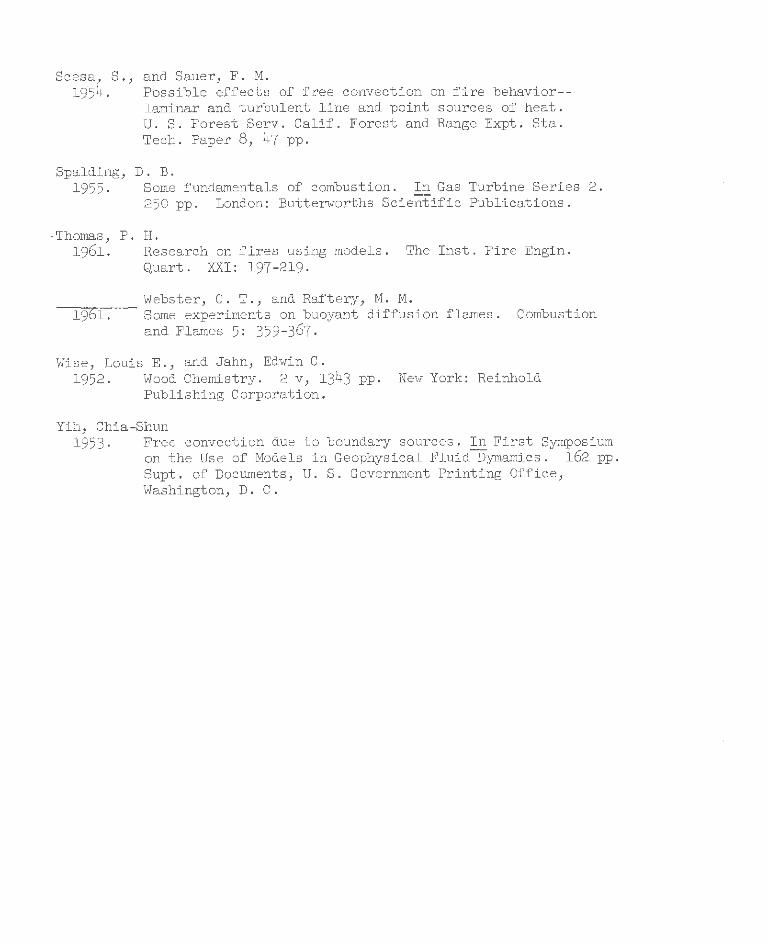
APPENDIX A
Table 4.--Experimental conditions for fires in cribs of vhite fir!fvood vith lateral spacing of 1 .25 inches
Fire RoomY Fuel and fuel bed parameters temp .
No. t d
I Mf I I I wf
I w
I ~ I I Io 0 0 Pf ~ 0 wb
~ In Percent Lbs/ft3 Lbs/ft3 Lbs Lbs /ft2 In In In
l 67 0.453 9.8 27 .1 7 .29 7.54 3.31 5.44 9 ·25 35·5 2 10 .453 9 .0 22.5 6.12 6.32 2.77 5.44 9.25 35 .5 3 10 .453 10.3 31.9 8 .47 8.76 3 .84 5.44 9.25 35 .5 4 72 .453 10.3 18.9 5.15 5.32 2.33 5.44 9·25 35 ·5 5 76 .453 10.4 24. 5 6.58 6.81 2 .99 5.44 9.25 35 ·5 6 13 .453 ll.l 24 .7 6.67 6.90 3.03 5.44 9·25 35 .5 1 72 .453 11.5 24 .1 6 .69 2.15 1.52 2.72 5·75 35 ·5
8 76 .453 10.6 24.1 6 .77 10.17 7 .17 12.70 5·75 35 ·5 9 72 .453 10.8 24.1 6.32 5.74 1.43 2.72 16 .25 35 ·5
10 75 .453 10 .9 24.1 6.34 26.91 6 .72 12 .70 16.25 35 ·5 11 71 .453 10.2 24 .4 6 .43 11.67 2.91 5.44 16.25 35 ·5 12 75 .453 10.2 24. 5 6.48 21.55 5.38 9.97 16 .25 35·5 13 75 .453 10.1 24 .3 6.60 15.93 6.99 12.70 9.25 35 .5 14 11 .453 10 .2 24.6 6.55 21.79 6 .94 12 .70 12.75 35 .5
15 73 .453 10 .4 29 .0 7 .78 10.81 ) .52 5.44 9.25 47.8 16 74 .989 10.2 24 .0 10.96 18.54 7 .21 7.91 10 .00 37.0 17 76 .454 10.6 24 .1 6.41 21.37 5·33 9·99 16 .25 35 ·5 18 74 .454 10.3 24.4 6.44 11.74 2.93 5.45 16 .25 35 .5 19 74 .286 10.8 24 .9 4.84 7 .60 3.23 8.01 9.50 35 .6 20 11 .68o 10 .7 24.0 8 .86 12.52 6.02 8.16 8.44 35 .4 21 8o 1.244 10 .4 24.0 12 .41 28.71 7 .72 7.46 8.75 61.2
- 45 -
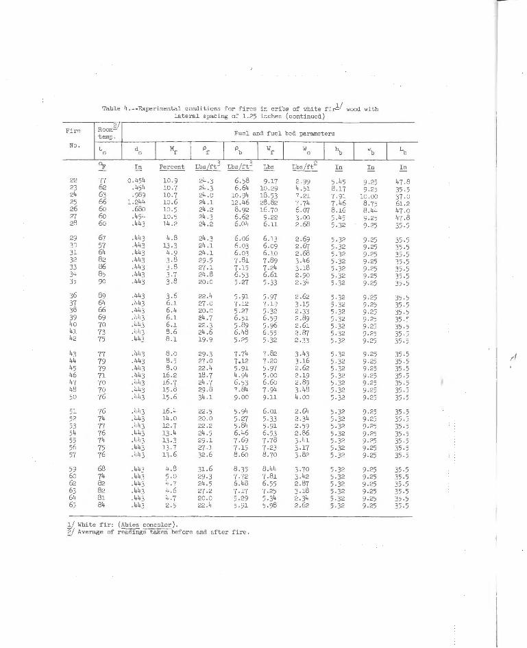
Table 4.--Experimental conditions for fires in cribs of white fir!/ wood with lateral spacing of 1.25 inches (continued)
Fire Roorn~U Fuel and fuel bed parameters temp.
No. t d l Mf I pf I pb I wf I y/
I ~ I wb I In 0 0 0
'T In Percent Lbs/ft3 Lbs/ft3 Lbs Lbs/ft2 In In In
22 77 o .454 10 . 9 24 .3 6.58 9.17 2 .99 5 .45 9.25 47 .8 23 62 .454 10 .7 24 .3 6.64 10 .29 4.51 8.17 9.25 35 .5 24 63 .989 10 .7 24 .0 10 .94 18 .53 7 .21 7.91 10 .00 37 .0 25 66 1.244 10.6 24 .1 12 .46 28 .82 7 .74 7.46 8.75 61.2 26 6o .68o 10 .5 24 .2 8.92 16 .70 6.07 8.16 8.44 47 .0 27 6o .454 10.5 24 .3 6.62 9 .22 3.00 5.45 9.25 47 .8 28 6o .443 14.2 24.2 6 .04 6.11 2 .68 5.32 9.25 35·5
29 67 .443 4.8 24 .3 6 .06 6.13 2 .69 5.32 9.25 35 ·5 30 57 .443 13 .3 24 .1 6 .03 6.09 2 .67 5.32 9 .25 35 ·5 31 64 .443 4.9 24 .1 6 .03 6.10 2 .68 5.32 9 .25 35 ·5 32 82 .443 3.8 29 .5 7 .81 7.89 3 .46 5.32 9 .25 35 ·5 33 86 .443 3.8 27 .1 7.15 7.24 3 .18 5.32 9 .25 35 ·5 34 85 .443 3.7 24 .8 6. 53 6.61 2.90 5.32 9.25 35·5 35 90 .443 3.8 20;0 5.27 5.33 2.34 5.32 9 .25 35 .5
36 89 .443 3.6 22 .4 5.91 5.97 2 .62 5.32 9 .25 35 .5 37 64 .443 6 .1 27 .0 7.12 7 .1) 3.15 5.32 9.25 35 ·5 38 66 .443 6 .4 20 .0 5.27 5.32 2.33 5.32 9.25 35 .5 39 69 .443 6 .1 24.7 6.51 6 .59 2 .89 5.32 9.25 35 · ~ 40 70 .443 6 .1 22 .3 5.89 5.96 2 .61 5.32 9.25 35 ·5 41 73 .443 8.6 24 .6 6.48 6 .55 2 .87 5.32 9.25 35 ·5 42 75 .443 8.1 19 .9 5.25 5.32 2.33 5.32 9.25 35 .5
43 77 .443 8 .0 29 .3 7.74 7 .82 3.43 5.32 9.25 35 .5
"' 44 79 .443 8 .5 27.0 7.12 7.20 3.16 5.32 9.25 35 ·5 45 79 .443 8.0 22 .4 5.91 5.97 2 .62 5.32 9.25 35 .5 46 71 .443 16.2 18 .7 4.94 5.00 2 .19 5.32 9.25 35 .5 47 70 .443 16.7 24 .7 6.53 6.60 2.89 5.32 9.25 35 .5 48 70 .443 15 .8 29 .8 7 .84 7 .94 3.48 5.32 9.25 35 .5 50 76 .443 15 .6 34.1 9.00 9.11 4 .00 5.32 9.25 35 ·5
51 76 .443 16 .4 22 .5 5.94 6.01 2 .64 5.32 9.25 35 .5 52 74 .443 14 .o 20 .0 5.27 5·33 2 .34 5.32 9.25 35 .5 53 77 .443 12 .7 22.2 5.84 5.91 2.59 5.32 9.25 35 .5 54 76 .443 13 .4 24 .5 6.46 6 .53 2 .86 5.32 9.25 35 .5 55 74 .443 13 .3 29 .1 7 .69 7.78 3.41 5.32 9 .25 35 ·5 56 75 .443 13 .7 27 .1 7 .15 7.23 3 .17 5.32 9 .25 35 .5 57 76 .443 13 .6 32.6 8 .60 8.70 3.82 5.32 9.25 35 · 5
59 68 .443 4 .8 31.6 8 .35 8.44 3 .70 5.32 9 .25 35 .5 60 74 .443 5.0 29.3 7 .72 7.81 3 .42 5.32 9 .25 35 .5 62 82 .443 4.7 24 .5 6.48 6.55 2.87 5.32 9 .25 35 .5 63 82 .443 4 .6 27 .2 7 .17 7.25 3.18 5.32 9 .25 35 ·5 64 81 .443 4 .7 20.0 5.29 5.34 2.34 5.32 9 ·25 35 ·5 65 84 .443 2 .5 22 .4 5.91 5.98 2.62 5.32 9 .25 35 ·5
y White :fir: (~ concolor) . g/ Average of readings taken before and after fire .
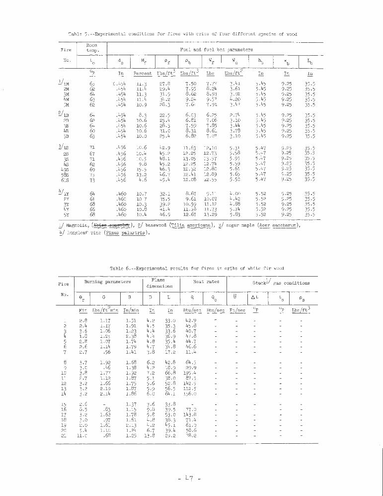
Table 5. --Experimental conditions for fires with cribs of four different species of wood
Room Fire temp. Fuel and fuel bed parameters
No . t o d 0 I Mf I Pr I pb I wf I w 1 ~ I w I Io 0 b
~ In Percent Lbs/rt3 Lbs/ft3 Lbs Lbs/ft2 In In In
ylM 65 0.454 11.3 27.8 7.50 7 .77 3 .41 5.45 9.25 35·5 2M 62 .454 11.4 29.4 7·95 8.24 3.61 5.45 9.25 35.5 3M 64 .454 11.3 31.9 8.62 8.93 3.92 5.45 9.25 35 ·5 4M 63 .454 11.4 34 .2 9.24 9.57 4 .20 5.45 9.25 35.5 5M 62 .454 10.9 28.3 7.64 7.91 3.47 5.45 9.25 35.5
stlll 64 .454 8.3 22 .5 6.03 6.25 2.74 5.45 9.25 35.5 2B 62 .454 10.6 25 .4 6.81 7.o6 3.10 5.45 9.25 35.5 3B 64 .454 10.6 28.3 7.59 7 .85 3 .44 5.45 9.25 35.5 4B 60 .454 10.6 31.0 8 .31 8.61 3.78 5.45 9.25 35 .5 5B 63 .454 10.0 25 .4 6.82 7.07 3.10 5.45 9.25 35·5
l/]J3 71 .456 10.6 42.9 11.63 12.10 5.31 5.47 9.25 35 .5 2S 67 .456 10.4 45.2 12.25 12.73 5.58 5.47 9 .25 35.5 3S 71 .456 10.5 48.1 13 .05 13 .57 5.95 5.47 9·25 35·5 4s 62 .456 9.8 45.2 12.25 12.74 5.59 5.47 9·25 35·5
49S 69 .456 15.5 46.3 12.32 12.80 5.61 5.47 9.25 35·5 58s 75 .456 13.2 46.7 12 .41 12.89 5.65 5 .47 9.25 35.5 6113 73 .456 4.6 45.4 12 .o8 12.55 5.50 5.47 9·25 35 .5
~/lY 64 .460 10.7 32.1 8.67 9.11 4.00 5.52 9.25 35.5 2Y 61 .46o 107 35·5 9 .61 10.07 4.42 5.52 9.25 35.5 3Y 68 .460 10.3 39.2 10.59 11.12 4.88 5.52 9.25 35.5 4Y 66 .46o 10.8 41.4 11.18 11.73 5.14 5.52 9.25 35 ·5 5Y 68 .46o 10.4 46.9
f 12.67 13.29 5.83 5.52 9.25 35·5
y Magnolia, ( o;e;;,ee uawlol!!l: ), gj basswood (Tilia americana), }/ sugar maple (Acer saccharum), ~/ longleaf pine (Pinus palustris).
Table G.--Experimental results for fires in cribs of white fir wood
Burning parameters Flame Heat rates Stack!/ gas conditions Fire dimensions
No. Gr I G I R D 1 L Q I Qc u t ~t I \I Ps
Min LbsLrt2min InLmin In In Btu/sec BtuLsec FtLsec OF OF LbsLrt3
1 2.8 1.17 1.51 4.2 33 .0 42.9 2 2.4 1.17 1.91 4.5 35.3 45.8 3 3.6 l.o6 1.23 4 .4 33 .6 40.7 4 1.8 1.25 2.38 4.4 36.9 47.8 5 2.8 1.07 1.74 4.8 35.4 44 .7 6 2.6 1.14 1.79 4.7 34.8 46.6 7 2.7 .56 1.41 3.8 17.2 11.4
8 3·7 1.92 1.68 6.2 42.8 64.5 9 3.0 .46 1.38 4.2 18.9 29.9
10 3.8 l. 77 1.92 7.2 66.8 195 .4 11 2.7 1.12 1.87 5.1 38.0 87 .5 12 3.2 1.66 l. 75 5.6 52.8 142 .5 13 3.2 2.19 1.87 5·9 56.5 112 .5 14 3·2 2.14 1.86 6.0 64.1 156.0
15 2.6 1.37 3.6 33 .8 16 8.5 .83 1.15 9.8 39 .5 n .o 17 3.2 1.62 1.78 5.8 53.0 143 .8 18 3.0 .97 1.61 4.8 38.3 71.4 19 2.0 1.61 2.13 4.2 45 .1 61.0 20 5.4 1.10 1.24 6.7 39 .4 58.6 21 11.0 .68 1.25 13.8 29.2 78.2
- 47 -
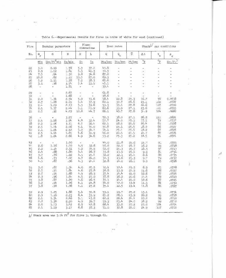
Table G. --Experimental results £or £ires in cribs o£ Yhite £i r Yood (continued)
Fire Burning parameters Flame Heat rates Stack!/ gas conditions dimensions
No . er I G I R D I L Q I Qc u lt:.t I ts I p s
Min Lbs[ft2min In[min In In Btu[sec Btu[ sec Ft[sec oF OF Lbs/£t3
22 3.0 0.99 1.78 5.3 37 .2 45 .8 23 2.9 1.52 1.81 5·3 41. 3 70.3 24 7.5 .94 1.30 9.8 34 .6 87 .0 25 12 .2 .62 1.10 13.5 27 .0 69.3 26 5.2 1.15 1.38 7.2 38 .3 65 .6 27 3.1 .96 1.74 5.4 33 ·5 45 .1 28 1.71 39 .4
29 2 .67 61.8 30 1.68 38 .6 31 2.0 1.34 2 .54 5.0 33.6 58.4 22.8 25.3 16.2 78 0.0738 32 2.7 1.28 2.03 5.4 37.9 60.1 32 .7 26.6 23.1 102 .0707 33 2.4 1.29 2 .19 5.3 39 .6 59.3 33 .1 27.8 22.6 107 .0700 34 2.1 1.37 2 .44 5.1 40.9 60.6 33 .9 27.1 23 .6 105 .0703 35 2.5 ·92 4.29 10.8 44.7 86.1 49.7 27.8 34 .9 124 .o68o
36 3.23 72 .3 38.0 27.1 26.9 115 .0691 37 2.5 1.26 1.94 4.8 32.4 52 .7 24.0 25.3 17.1 79 .0737 38 2.2 1.06 3.11 6.7 36.4 62 .1 28.5 25.5 20.4 85 .0728 39 2.5 1.14 2 .06 5.1 35.0 50.8 25.1 25.5 18.0 86 .0727 40 2.1 1.24 2 .42 5.0 34.7 54.1 25.4 25.5 18.2 87 .0725 41 2.5 1.14 1.85 4.6 31.9 46.0 20.5 25.5 14.7 87 .072!) 1+2 1.8 1.24 2 .66 4.9 34.6 53 .2 25.3 25.2 18.5 91 .0721
43 1.50 44 .0 21.8 25 .6 15.7 91 .0721 44 2 .6 1.16 1.70 4. 5 32 .6 46.0 22.5 25 .7 16 .2 93 .0718 45 2 .2 1.14 2 .31 5.2 34 .5 52 .0 25 .3 25 .7 18.3 97 .0713 46 2 .4 .88 1.80 4.4 26.7 33 .8 13.9 25 .4 9 ·9 81 .0734 rl 47 3.7 .76 1.22 4.5 25.4 30.2 12 .1 25 .4 8 .6 8o .0735 48 4.6 ·73 1.02 4.7 24 .0 30.3 13.6 25 .3 9·7 79 .0737 50 4 .5 .87 .96 4.3 24 .4 32 .8 14.2 26.1 9·9 85 .0728
51 3.0 .87 1.34 4.0 25.5 30.4 12 .4 25.5 8 .9 85 .0728 52 2 .5 .91 1.84 4.6 27.8 36 .8 13.9 21.9 11.6 86 .0727 53 2 .7 ·95 1.68 4.5 28.3 37 .4 14.4 21.0 12.6 87 .0725 54 2.9 .96 1.54 4.5 27.0 37 .8 16.2 20 .6 14.4 89 .0723 55 3.8 .87 1.20 4.6 26 .5 35 .1 14 .4 21.0 12.6 87 .0725 56 3.2 .94 1.26 4.1 24.8 34.0 12 .0 19.4 11.3 84 .0730 57 3.8 .98 l.o8 4.1 27.8 35 .4 12 .5 19.4 11 .8 86 .0727
59 2.9 1.25 1.88 5.4 30.8 59 .1 19.7 27 .2 13.1 81 .0734 6o 2 .9 1.16 2.23 6.4 33.9 65.2 26.1 23.9 20.2 93 .0718 62 2.1 1.34 2.46 5.1 43.8 6o.2 26.4 24.4 20.2 99 .0710 63 2.2 1.38 2.20 4.9 39 ·7 59.3 23 .4 24.0 18 .2 99 .0710 64 2 .0 1.13 3.42 6.9 42.8 68.4 33 .2 27.2 23.0 lo4 .07o4 65 2 .1 1.19 3.17 6.8 37 ·3 71.0 32 .8 25.0 24 .9 107 .0700
!/Stack area vas 3.14 ft2 for fires 31 through 65 .
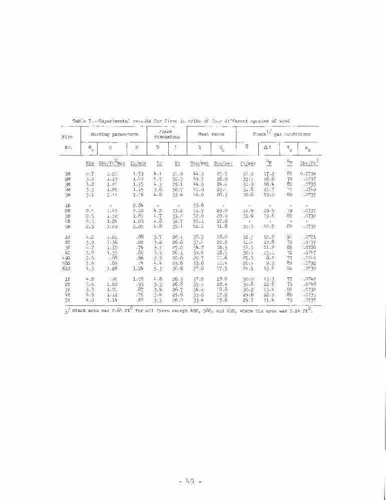
Table 7 .--Experimental result s f or fires i n cribs of four dif ferent species of wood
Burning parameters Flame Heat rates Stack!/ gas condit ions Fi re dimensi ons
No. ~r I G I R D l L Q I Qc u I A t I ts l Ps
Min LbsLft2m1n I nLmin In In Bt u/sec Btu/sec FtLsec OF <>p. Lbs/rt3
1M 2.7 1.25 1.53 4 .1 31.9 44. 3 25 .5 31.9 17 .2 81 0.0734 2M 3-2 1.13 1.49 4.7 30-3 45 .7 26 .0 33 -5 16.6 79 -0737 3M 3-2 1.21 1.35 4 .3 29 .1 44 .9 24 .4 31.9 16 .4 8o .0735 4M 3-3 1.25 1.15 3-8 30-7 41.0 23 .4 31.8 15 .7 77 .0740 5M 3-l l.ll 1.56 4 .8 33 .4 46.0 28 .3 30.6 19 -9 8o .0735
lB 2.64 59.6 2B 2.1 1.45 2.02 4.2 33 -2 51.3 29 .0 31.9 19 -5 79 .0737 3B 2.5 1.32 1.85 4.7 33 -2 52 .0 29 .0 31.9 19.6 82 .0732 4B 2.9 1.24 1.63 4 .8 32 -7 50.1 27 .6 5B 2.3 1.29 2.05 4 .8 35 .1 52 .1 31.8 30 .5 22 .5 82 ·0732
18 4.2 1.21 .88 3-7 26 .1 38-5 18.0 32 .3 12.2 91 .0721 2S 3-9 1.36 .82 3-2 26 .6 37. 4 20 .2 31.4 13 .8 79 .0737 3S 4.7 1.15 .74 3-5 25 .2 34.7 16 .3 31. 5 11.2 85 .. 0728 4S 3.8 1.39 .86 3·3 26 .1 39-5 18 .9 30 .5 13 .1 72 .0747
498 5-9 .88 .66 3-9 20.8 29 .7 11 .6 25 .3 8.2 77 .0740 588 5-9 .89 .74 4 .4 23 .8 33 .6 10.5 20 .5 9-3 82 .0732 618 4.3 1.26 1.24 5-3 30 .6 57 .8 17 .5 24 .1 13 .2 84 ·0730
1Y 4. 2 .91 1.08 4.6 26.3 37.2 18 .8 30 .0 13.3 75 .0742 2Y 3-5 1.22 .93 3-3 26 .8 35 -5 18 .4 30 .8 12.6 71 .0748 3Y 3-9 1.21 .87 3.4 26 .7 36.4 18.8 30 .2 13.4 82 .0732 4Y 4. 5 1.12 .76 3.4 25 .6 33 .6 17 .2 29 .6 12 .5 8o .0735 5Y 4.9 1.14 .67 3·3 26 .2 33 .4 15.8 2-, .7 11.4 79 .0737
1/ Stack area was 2 . 64 ft for all f ires except 498, 588, and 618, where the area was 3.14 f t 2.
- 49 -
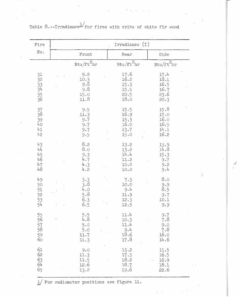
Table 8.--Irradiance!/for fires with cribs of white fir wood
Fire Irradiance (I) No. Front Rear Side
Btu/ft2hr Btu/ft~r 2 Btu/ft hr
31 9.2 17.6 17.4 32 10.3 16.2 18.1 33 9.8 15 .3 16.5 34 9.8 15.5 16.7 35 15.0 20.5 23.6 36 11.8 18.0 20 .3
37 9·5 15.5 15.8 38 11.3 16.9 17.0 39 9·7 15 .3 16.0 4o 9.7 16.0 16.5 41 9·7 13.7 14.1 42 9.5 15 .0 16 .2
43 8.2 13.2 13.9 44 8 .0 13.2 14.8 45 9·3 14 .4 15.3 46 4.7 11.2 9.7 47 4.3 10 .0 9.2 ,.I
48 4.2 10 .0 9.4
49 3.3 7·3 8 .0 50 3.8 10.0 9.9 51 4.0 9.4 8.5 52 5 .8 11.9 9.7 53 6 .3 12.3 10.1 54 6.5 12.5 9.9
55 5·5 11.4 9.7 56 4.8 10 .3 7.8 57 5 .0 11.4 9.0 58 5 .0 9.4 7.8 59 11.7 18 .6 16.0 60 11.3 17 .8 14.6
61 9.0 13.2 11.5 62 11. 3 17 .3 16 .5 63 11.5 18.2 16 .9 64 12 .6 18.7 18 .1 65 13.2 19.6 22 .6
!/ For radiometer positions see figure 11 .
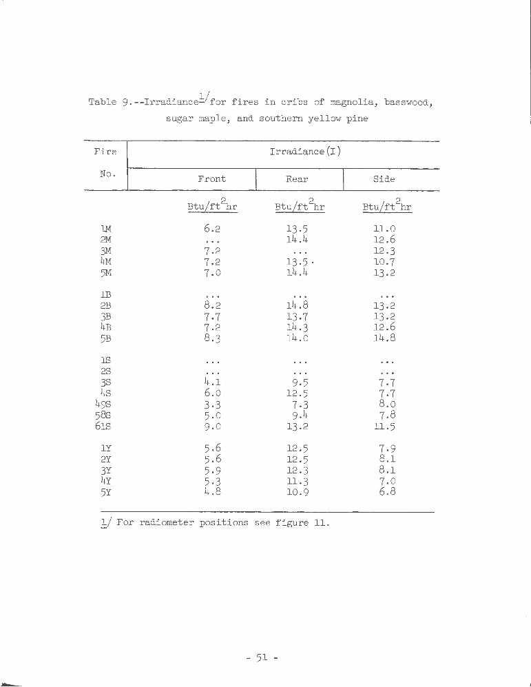
Table 9.--Irradiance~/for fires in cribs of magnolia, basswood,
sugar maple, and southern yellow pine
Fire Irradiance(I)
No. Front Rear Side
2 BtuLft hr
2 BtuLrt hr BtuLft~r
1M 6.2 13.5 11.0 2M 14.4 12.6 3M 7.2 12.3 4M 7.2 13.5. 10.7 5M 7.0 14.4 13.2
lB 2B 8.2 14.8 13.2 3B 7·7 13.7 13.2 4B 7.2 14.3 12.6 5B 8.3 14.0 14.8
lS 28 38 4.1 9·5 7.7 4s 6.0 12.5 7·7
498 3-3 7·3 8.0 588 5.0 9.4 7.8 618 9.0 13.2 11.5
lY 5.6 12.5 7.9 2Y 5.6 12.5 8.1 3Y 5·9 12.3 8.1 4Y 5·3 11.3 7.0 5Y 4.8 10.9 6.8
~/ For radiometer positions see figure 11.
,,
- 51 -
APPENDIX B
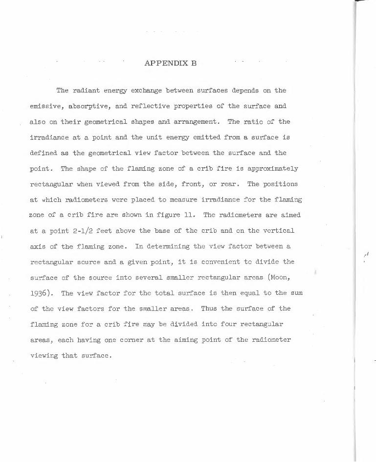
The radiant energy exchange between surfaces depends on the
emissive, absorptive, and reflective properties of the surface and
also on their geometrical shapes and arrangement. The ratio of the
irradiance at a point and the unit energy emitted from a surface is
defined as the geometrical view factor between the surface and the
point. The shape of the flaming zone of a crib fire is approximately
rectangular when viewed from the side, front, or rear. The positions
at which radiometers were placed to measure irradiance for the flaming
zone of a crib fire are shown in figure 11. The radiometers are aimed
at a point 2-1/2 feet above the base of the crib and on the vertical
axis of the flaming zone. In determining the view factor between a
rectangular source and a given point, it is convenient to divide the
surface of the source into several smaller rectangular areas (Moon,
1936). The view factor for the total surface is then equal to the sum
of the view factors for the smaller areas. Thus the surface of the
flaming zone for a crib fire may be divided into four rectangular
areas, each having one corner at the aiming point of the radiometer
viewing that surface.
-
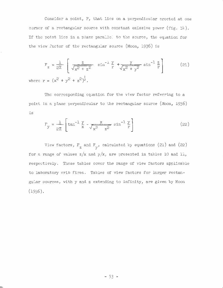
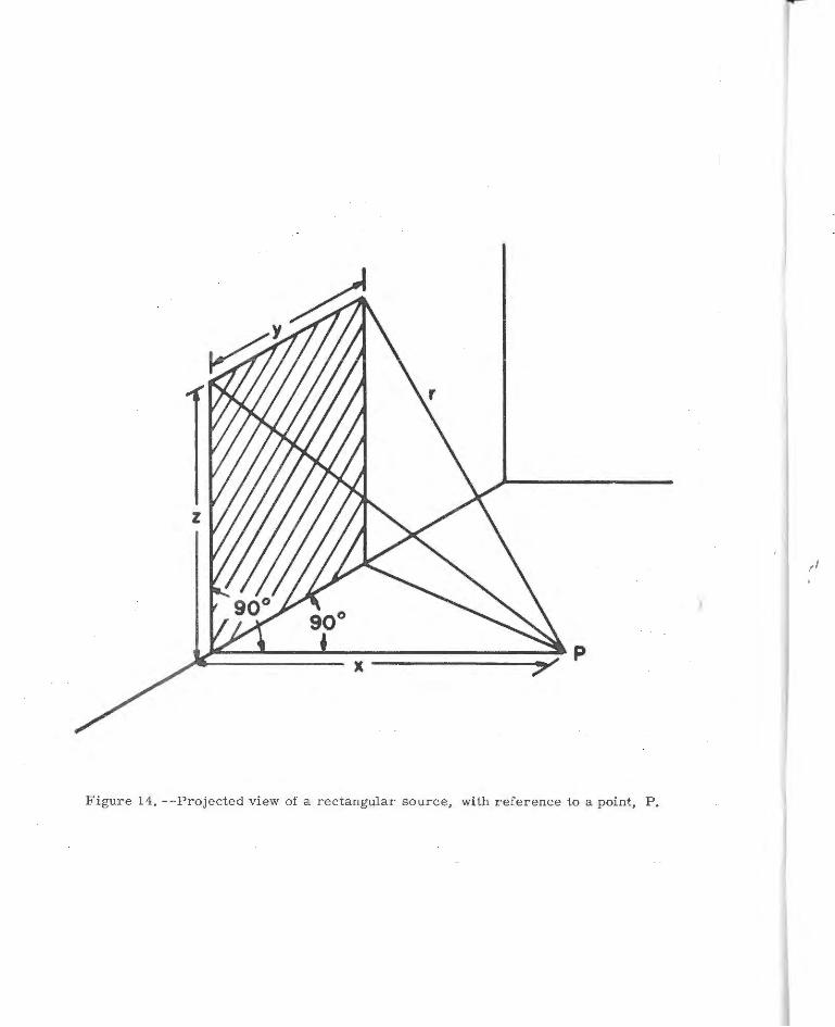
Consider a point, P, that lies on a perpendicular erected at one
corner of a rectangular source with constant emissive power (fig. 14).
If the point lies in a plane parallel to the source, the equation for
the view factor of the rectangular source (Moon, 1936) is
1 [ z F z - 2IT .J x2 + z2
l
where r = (x2 + y2 + z2)2.
(21)
The corresponding equation for the view factor referring to a
point in a plane perpendicular to the rectangular source (Moon, 1936)
is
F = ~ [ tan- l ~ y 2JI X
-,.===x== sin -l ~ J .J x2 z2
(22)
View factors, F and F , calculated by equations (21) and (22) z y
for a range of values z/x and y/x, are presented in tables 10 and 11,
respectively. These tables cover the range of view factors applicable
to laboratory crib fires . Tables of view factors for larger rectan-
gular sources, with y and z extending to infini ty, are given by Moon
(1936).
- 53 -
--
Figure 14, --Projected view of a rectangular source, with reference to a point, P.
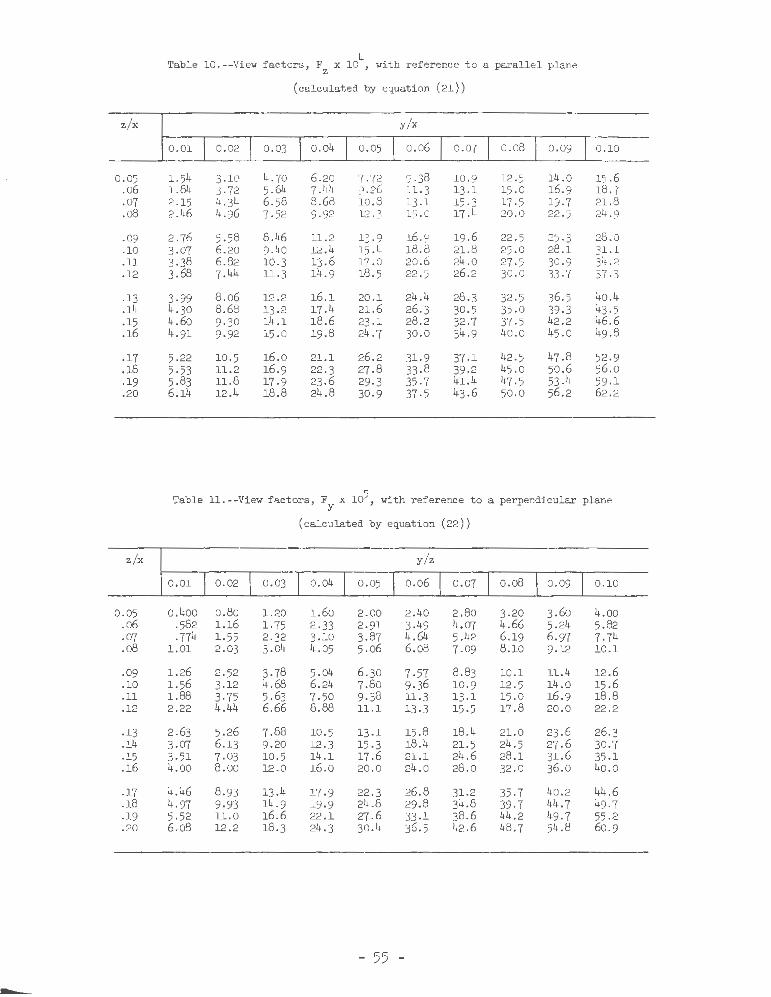
Table 10.--View factors, F x 104, with reference to a parallel plane z (calculated by equation (21))
z/x y/x
0. 01 0.10
0.05 1.54 3.10 4.70 6.20 7.72 9.38 10.9 12 .5 14.0 15 .6 .o6 1.84 3-72 5.64 7.44 9.26 11.3 13 .1 15 .0 16.9 18.7 -07 2.15 4.34 6.58 8.68 10.8 13.1 15.3 17 .5 19.7 21.8 .o8 2.46 4.96 7.52 9-92 12 .3 15.0 17.4 20.0 22 .5 24 .9
.09 2.76 5.58 8.46 ll .2 13.9 16.9 19 .6 22 .5 25 .3 28 .0
.10 3.07 6.20 9.40 12.4 15.4 18.8 21.8 25 .0 28.1 31.1
.ll 3.38 6.82 10.3 13.6 17.0 20.6 24 .0 27 .5 30.9 34 .2
.12 3.68 7.44 11.3 14.9 18.5 22.5 26 .2 30.0 33 -7 37-3
.13 3.99 8.o6 12.2 16.1 20 .1 24.4 28.3 32 .5 36.5 40 .4
.14 4.30 8.68 13.2 17.4 21.6 26.3 30.5 35.0 39·3 43.5
.15 4.60 9.30 14.1 18.6 23 .1 28.2 32 .7 37 .5 42 .2 46.6
.16 4.91 9.92 15.0 19.8 24.7 30.0 34.9 40 .0 45.0 49.8
.17 5.22 10.5 16.0 21.1 26.2 31.9 37 .1 42 .5 47 .8 52.9
.18 5·53 11.2 16.9 22 .3 27.8 33 .8 39-2 45 .0 50 .6 56.0
.19 5.83 ll.8 17.9 23.6 29 .3 35.7 41.4 47-5 53.4 59 -1
.20 6.14 12.4 18.8 24 .8 30.9 37.5 43.6 50.0 56 .2 62.2
Table 11.- -View factors, F x 105, with reference to a perpendicular plane y (calculated by equation (22))
z/x y/z
0.01 0.10
0.05 0.400 o.8o 1.20 1.60 2.00 2.40 2.80 3.20 3.6o 4.00 .o6 .582 1.16 1.75 2-33 2.91 3.49 4.07 4.66 5.24 5.82 .07 .774 1.55 2.32 3.10 3.87 4.64 5.42 6.19 6.97 7. 74 .o8 1.01 2.03 3.o4 4.05 5.06 6.o8 7. 09 8.10 9.12 10.1
.09 1.26 2.52 3.78 5.o4 6.30 7.57 8 .83 10.1 11.4 12 .6
.10 1.56 3.12 4.68 6.24 7.8o 9.36 10.9 12 .5 14.0 15 .6
.ll 1.88 3·75 5.63 7·50 9.38 11.3 13 .1 15 .0 16.9 18.8
.12 2.22 4.44 6.66 8.88 11.1 13 .3 15.5 17 .8 20 .0 22 .2
.13 2.63 5.26 7.88 10 .5 13 .1 15.8 18.4 21.0 23 .6 26.3
.14 3.07 6.13 9.20 12 -3 15.3 18.4 21.5 24 .5 27 .6 30.7
.15 3.51 7.03 10.5 14.1 17.6 21.1 24.6 28 .1 31.6 35.1
.16 4.00 8 .00 12.0 16.0 20 .0 24.0 28.0 32.0 36.0 4o.o
.17 4.46 8.93 13.4 17·9 22.3 26 .8 31.2 35·7 40 .2 44.6
.18 4.97 9.93 14 .9 19.9 24.8 29 .8 34.8 39 .7 44 .7 49.7
.19 5.52 11.0 16.6 22.1 27 .6 33 .1 38.6 44.2 49 .7 55 .2
.20 6.o8 12.2 18.3 24.3 30.4 36.5 42 .6 48 .7 54 .8 60.9
- 55 -
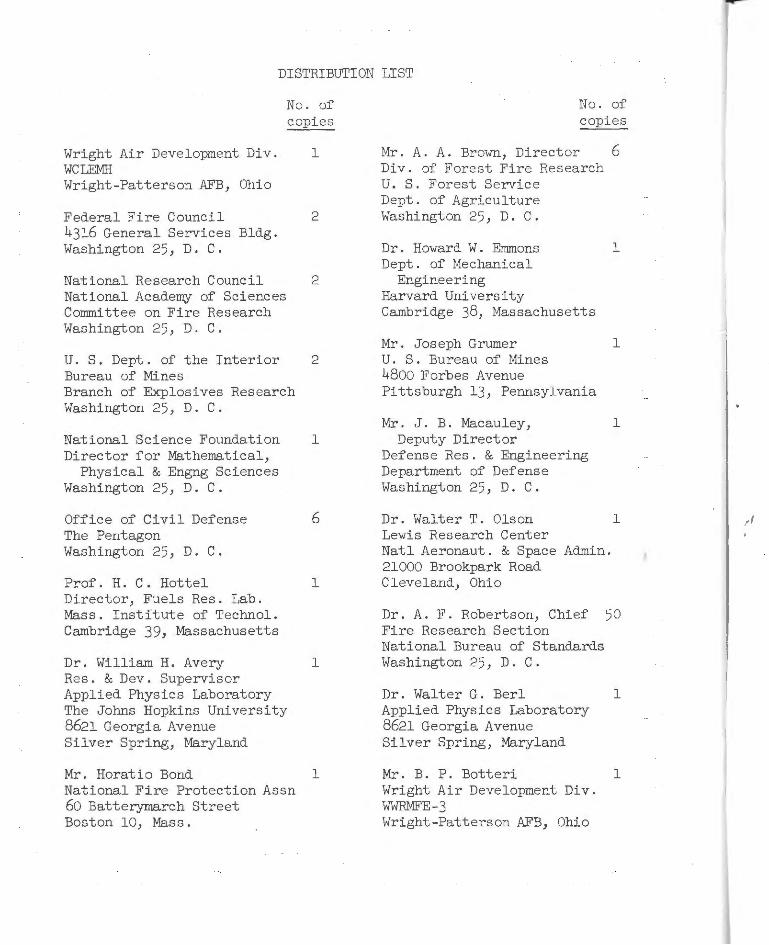
DISTRIBUTION LIST
No. of copies
Wright Air Development Div. WCLEMH Wright-Patterson AFB, Ohio
Federal Fire Council 4316 General Services Bldg. Washington 25, D. C.
National Research Council National Academy of Sciences Committee on Fire Research Washington 25, D. C.
l
2
2
U. S. Dept . of the Interior 2 Bureau of Mines Branch of Explosives Research Washington 25, D. C.
National Science Foundation l Director for Mathematical,
Physical & Engng Sciences Washington 25, D. C.
Office of Civil Defense The Pentagon Washington 25, D. C.
Prof. H. C. Hottel Director, Fuels Res. Lab. Mass. Institute of Technol. Cambridge 39, Massachusetts
Dr. William H. Avery Res. & Dev. Supervisor Applied Physics Laboratory The Johns Hopkins University 8621 Georgia Avenue Silver Spring, Maryland
Mr. Horatio Bond National Fire Protection Assn 60 Batterymarch Street Boston 10, Mass.
6
l
l
l
No. of copies
Mr. A. A. Broym, Director 6 Div. of Forest Fire Research U. S. Forest Service Dept. of Agriculture Washington 25, D. C.
Dr. Howard W. Emmons l Dept . of Mechanical
Engineering Harvard University Cambridge 38, Massachusetts
Mr. Joseph Grumer l U. S. Bureau of Mines 48oo Forbes Avenue Pittsburgh 13, Pennsylvania
Mr. J. B. Macauley, l Deputy Director
Defense Res. & Engineering Department of Defense Washington 25, D. C.
Dr. Walter T. Olson l Lewis Research Center Natl Aeronaut. & Space Admin. 21000 Brookpark Road Cleveland, Ohio
Dr. A. F. Robertson, Chief 50 Fire Research Section National Bureau of Standards Washington 25, D. C.
Dr. Walter G. Berl l Applied Physics Laboratory 8621 Georgia Avenue Silver Spring, Maryland
Mr. B. P. Botteri l Wright Air Development Div. WWRMFE-3 Wright-Patterson AFB, Ohio
,,
•
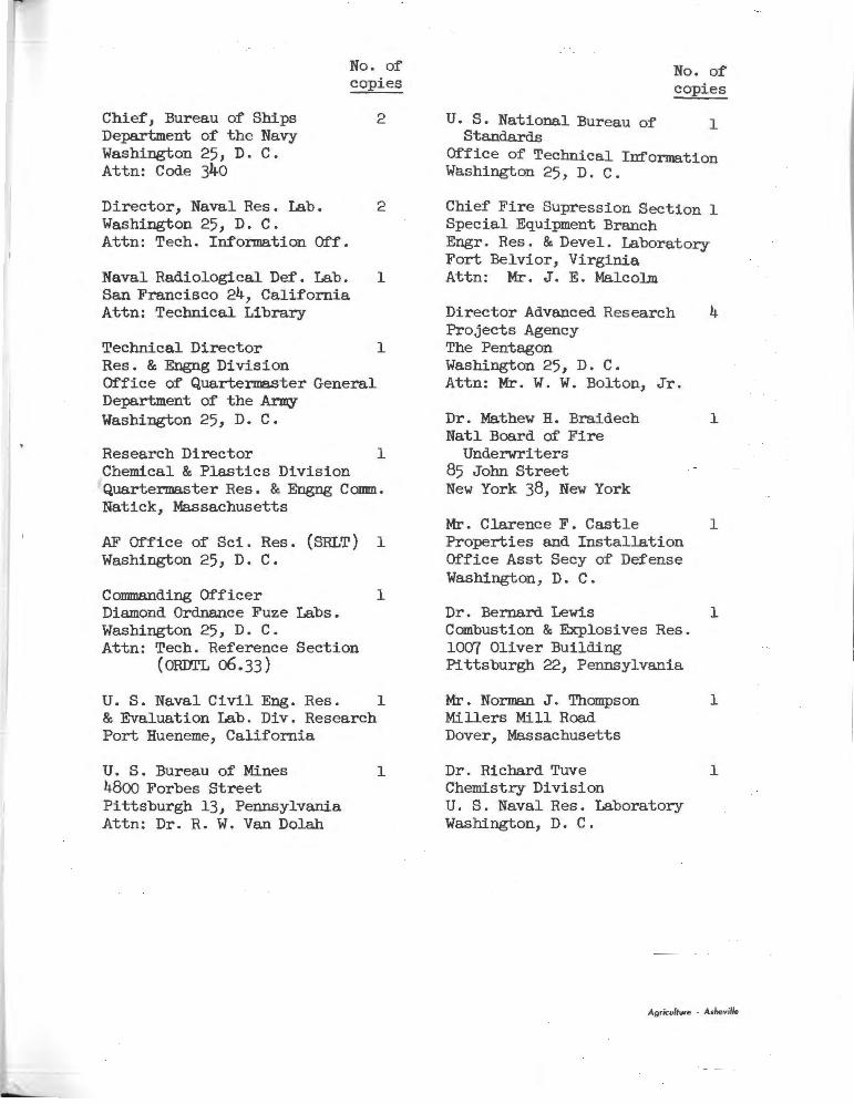
No. of copies
Chief, Bureau of Ships 2 Department of the Navy Washington 25, D. C. Attn: Code 340
Director, Naval Res • Lab. 2 Washington 25, D. C . Attn: Tech. In:forma.tion O:f:f.
Naval Radiological De:f. Lab. 1 San Francisco 24, California Attn: Technical Library
Technical Director 1 Res. & Engng Division Office of Quartermaster General Department of the ~ Washington 25, D. C.
Research Director 1 Chemical & Plastics Division Quartermaster Res. & Engng Comm. Natick, Massachusetts
AF O:f:fice of Sci. Res. (SRLT) 1 Washington 25, D. C •
Commanding Officer 1 Diamond Ordnance Fuze Labs. Washington 25, D . C • Attn: Tech. Reference Section
( ORIJI'L o6 • 33 )
U. S. Naval Civil Eng. Res. 1 & Evaluation Lab. Div. Research Port Hueneme, California
U. S. Bureau of Mines 4800 Forbes Street Pittsburgh 13, Pennsylvania Attn: Dr. R. W. Van Dolah
1
No. o:f copies
U. S. National Bureau o:f 1 Standards
Office of Technical Information Washington 25, D. C.
Chief Fire Supression Section 1 Special Equipment Branch Engr. Res. & Devel. Laboratory Fort Belvior, Virginia Attn: Mr. J. E. Malcolm
Director Advanced Research 4 Projects Agency The Pentagon Washington 25, D • C • Attn: Mr. W. W. Bolton, Jr.
Dr. Mathew H. Braidech 1 Natl Board o:f Fire
Underwriters 85 John Street New York 38, New York
Mr. Clarence F. Castle 1 Properties and Installation Office Asst Secy o:f De:fense Washington, D. C.
Dr. Bernard Lewis 1 Combustion & Explosives Res. 1007 Oliver Building Pittsburgh 22, Pennsylvania
Mr. Norman J. Thanpson 1 Millers Mill Road Dover, Massachusetts
Dr. Richard Tuve 1 Chemistry Division U. S. Naval Res. Laboratory Washington, D. C .
Ag<icullure - Asltevi//e
No. of copies
Office of Director of Defense 2 Research and Engineering The Pentagon Washington 25, D. C. Attn: Mr. Willis B. Foster
Southwest Research Institute 1 8500 Culebra Road San Antonio, Texas Attn: Dr. W. D. Weatherford
Dept. Mechanical Engineering 1 Inst. of Technology Univ. of Minnesota Minneapolis 14, Minnesota Attn: Prof. Perry L. Blackshear,Jr.
Battelle Memorial Institute 1 505 King Avenue Columbus 1, Ohio Attn: Mr. A. A. Putman
U. S. Forest Service Southern Forest Fire Lab. P. 0. Box 1421, Macon, Ga. Attn: K. W. McNasser
1