Embed Size (px)
Citation preview
1 Approved for Public Release 1
Summary of Wind Tunnel Tests and Vehicle
Analysis for Open Rotor Propulsion Systems
National Aeronautics and Space Administration
U.S.A.
Presentation to ICAO’s Noise
Technology Independent Expert Panel
February 1, 2012
https://ntrs.nasa.gov/search.jsp?R=20150010337 2019-05-26T13:43:54+00:00Z
2 Approved for Public Release 2
Acknowledgements
General Electric/CFM International
NASA
Subsonic Fixed Wing Project
Environmentally Responsible Aviation Project
Aeronautics Test Program
Arctic Slope Research Corporation
Federal Aviation Administration
Specific NASA Contributors:
Aeropropulsion Division
Structures and Materials Division
Facilities Division
Testing Division

3 Approved for Public Release 3
Model Scale Open Rotor
Wind Tunnel Tests
4 Approved for Public Release 4
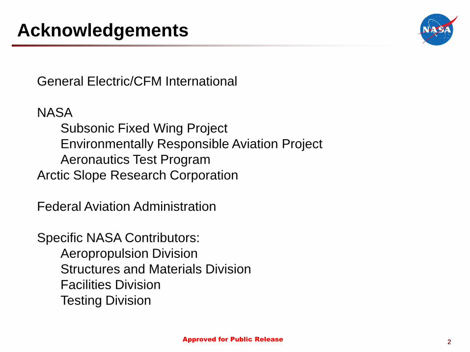
• Objective: Explore the design space for lower noise while
maintaining the high propulsive efficiency from a counter-rotating
open rotor system.
• Approach: A model scale, low-noise open rotor system was tested in
collaboration with General Electric (GE) and CFM International.
Candidate technologies for lower noise were investigated. Installation
effects such as pylon integration were investigated in partnership
with GE and the Federal Aviation Administration (FAA).
Historical Baseline
(12 x 10 Blade Count)
Gen-1 Blade Sets (NASA/GE)
Historical Baseline
Modern Baseline
4 Advanced Designs
Gen-2 Blade Sets (NASA/FAA/GE)
6 GE Advanced Designs
Pylon wake mitigation
NASA/FAA/GE Open Rotor Collaboration

5 Approved for Public Release 5
History (1/3) 2009
Aug Sep Oct Nov Dec
Drive Rig Rehab
and Installation
Drive Rig Checkout
Sep 24 – Oct 27
First Research Run
Oct 28
Linear Array Checkout
Dec 7-11
Influence Body Tests
Dec 14
6 Approved for Public Release
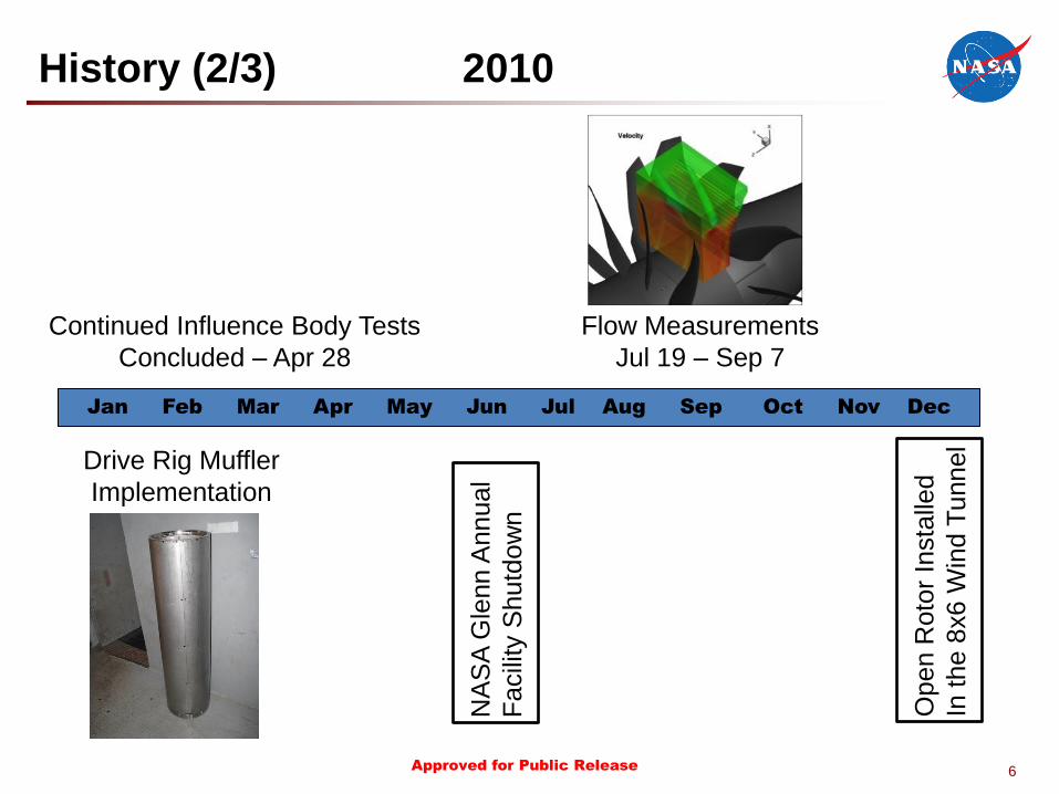
History (2/3) 2010
Jan Feb Mar Apr May Jun Jul Aug Sep Oct Nov Dec
NA
SA
Gle
nn A
nnual
Facili
ty S
hutd
ow
n
Drive Rig Muffler
Implementation
Continued Influence Body Tests
Concluded – Apr 28
Flow Measurements
Jul 19 – Sep 7
Open R
oto
r In
sta
lled
In the 8
x6
Win
d T
unnel
7 Approved for Public Release 7
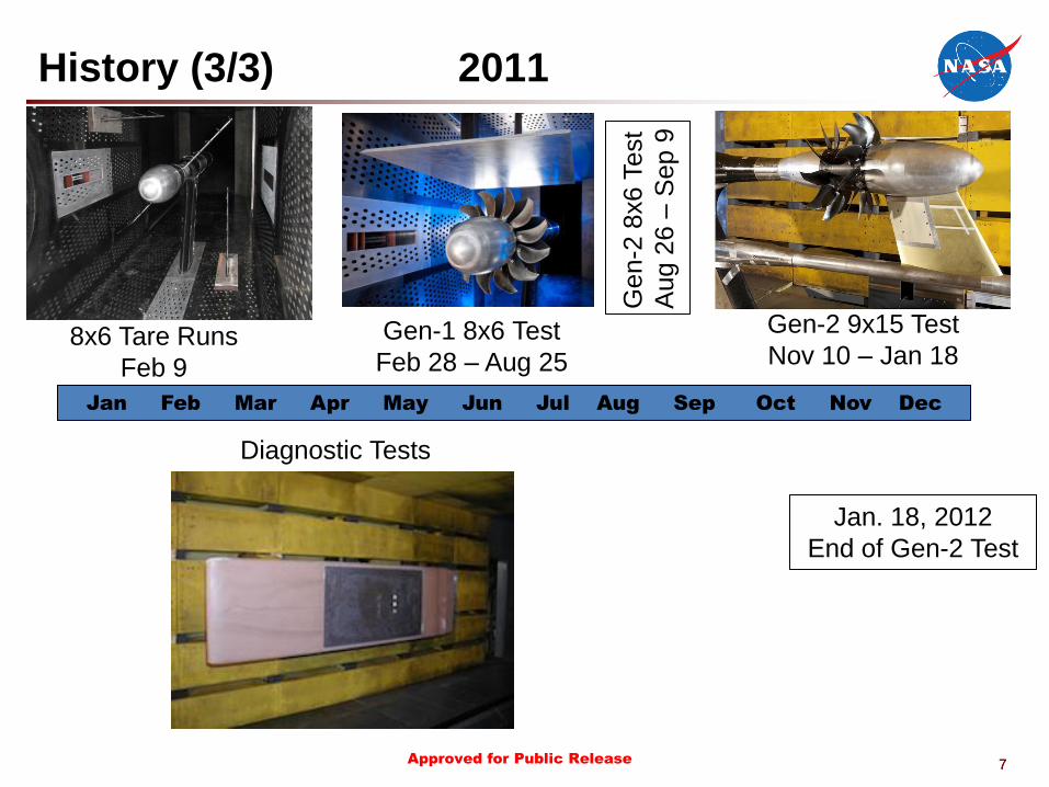
History (3/3) 2011
Jan Feb Mar Apr May Jun Jul Aug Sep Oct Nov Dec
Jan. 18, 2012
End of Gen-2 Test
Gen-2
8x6 T
est
Aug 2
6 –
Sep 9
Gen-1 8x6 Test
Feb 28 – Aug 25 8x6 Tare Runs
Feb 9
Gen-2 9x15 Test
Nov 10 – Jan 18
Diagnostic Tests
8 Approved for Public Release 8
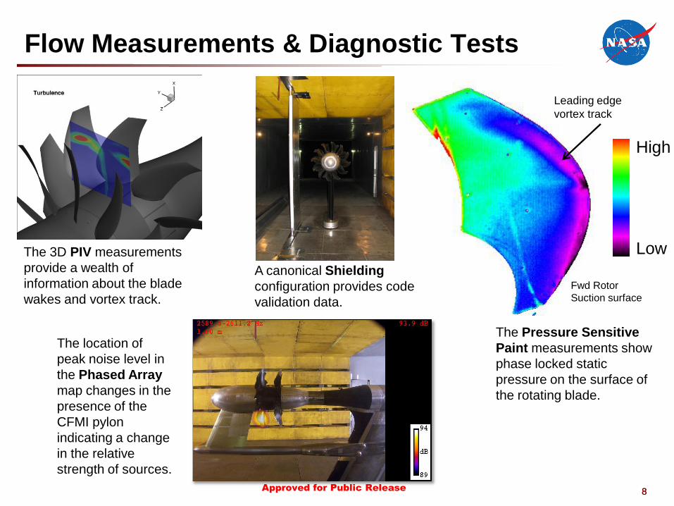
Low
High
The 3D PIV measurements
provide a wealth of
information about the blade
wakes and vortex track.
Leading edge
vortex track
Fwd Rotor
Suction surface
The Pressure Sensitive
Paint measurements show
phase locked static
pressure on the surface of
the rotating blade.
The location of
peak noise level in
the Phased Array
map changes in the
presence of the
CFMI pylon
indicating a change
in the relative
strength of sources.
A canonical Shielding
configuration provides code
validation data.
Flow Measurements & Diagnostic Tests

9 Approved for Public Release 9
Systems Analysis Results
of an Open Rotor Propulsion
System on an Advanced Single
Aisle Transport

10 Approved for Public Release
Background
10
• NASA’s systems analysis team has been investigating potential environmental
benefits of advanced propulsion systems on “Advanced” Single Aisle aircraft ‒ Direct Drive
‒ Geared Turbofan
‒ Open Rotor
• Open Rotor assessment is joint effort between NASA’s Subsonic Fixed Wing
(SFW) & Environmentally Responsible Aviation (ERA) projects
– SFW had FY11 milestone to assess fuel burn/noise characteristics of an
open rotor propulsion system
– ERA measured advanced open rotor blade performance/acoustic data
• ERA funded task with General Electric was conduit to NASA/industry partnership
– Enabled NASA access to data for use in system assessment
– Allowed coordination with industry on modeling approaches/technical assumptions
11 Approved for Public Release
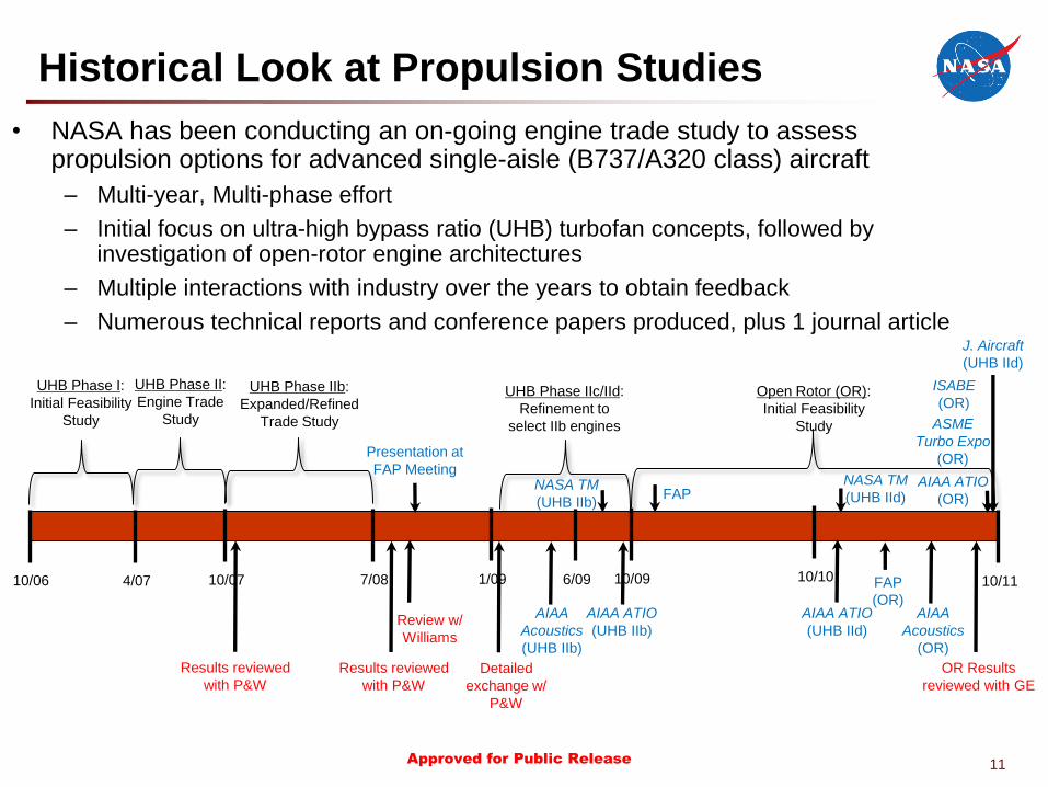
Historical Look at Propulsion Studies
• NASA has been conducting an on-going engine trade study to assess propulsion options for advanced single-aisle (B737/A320 class) aircraft
– Multi-year, Multi-phase effort
– Initial focus on ultra-high bypass ratio (UHB) turbofan concepts, followed by investigation of open-rotor engine architectures
– Multiple interactions with industry over the years to obtain feedback
– Numerous technical reports and conference papers produced, plus 1 journal article
10/06 4/07 10/07
Results reviewed
with P&W
UHB Phase I:
Initial Feasibility
Study
UHB Phase II:
Engine Trade
Study
7/08
UHB Phase IIb:
Expanded/Refined
Trade Study
Results reviewed
with P&W
Review w/
Williams
Presentation at
FAP Meeting
1/09
Detailed
exchange w/
P&W
UHB Phase IIc/IId:
Refinement to
select IIb engines
6/09 10/09
NASA TM
(UHB IIb) FAP
AIAA ATIO
(UHB IIb)
Open Rotor (OR):
Initial Feasibility
Study
10/10 10/11
NASA TM
(UHB IId)
OR Results
reviewed with GE
AIAA ATIO
(OR)
J. Aircraft
(UHB IId)
AIAA
Acoustics
(OR)
AIAA
Acoustics
(UHB IIb)
AIAA ATIO
(UHB IId)
ASME
Turbo Expo
(OR)
ISABE
(OR)
FAP
(OR)
12 Approved for Public Release
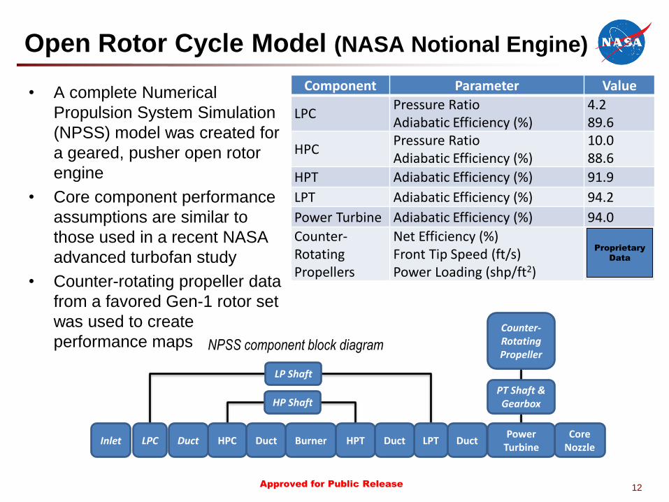
Open Rotor Cycle Model (NASA Notional Engine)
• A complete Numerical
Propulsion System Simulation
(NPSS) model was created for
a geared, pusher open rotor
engine
• Core component performance
assumptions are similar to
those used in a recent NASA
advanced turbofan study
• Counter-rotating propeller data
from a favored Gen-1 rotor set
was used to create
performance maps
PT Shaft & Gearbox HP Shaft
LP Shaft
Inlet LPC HPC Burner HPT LPT Core
Nozzle Duct Duct Duct Duct
NPSS component block diagram
Counter-Rotating Propeller
Power Turbine
Component Parameter Value
LPC Pressure Ratio Adiabatic Efficiency (%)
4.2 89.6
HPC Pressure Ratio Adiabatic Efficiency (%)
10.0 88.6
HPT Adiabatic Efficiency (%) 91.9
LPT Adiabatic Efficiency (%) 94.2
Power Turbine Adiabatic Efficiency (%) 94.0
Counter-Rotating Propellers
Net Efficiency (%) Front Tip Speed (ft/s) Power Loading (shp/ft2)
Proprietary
Data

13 Approved for Public Release
Open Rotor Engine Performance
Flight Condition Engine Performance Parameter Value
Top of Climb (M0.78, 35kft)
Net Thrust (lbf) TSFC (lbm/hr/lbf) OPR OR Advance Ratio OR Power Coefficient OR Thrust Coefficient OR Net Efficiency (%)
5000 0.428 42.0
Rolling Takeoff (M0.25, 0 ft, +27F)
Net Thrust (lbf) TSFC (lbm/hr/lbf) OPR OR Advance Ratio OR Power Coefficient OR Thrust Coefficient OR Net Efficiency (%)
19,000 0.229 28.5
Sea Level Static (M0.0, 0 ft, +27F)
Net Thrust (lbf) TSFC (lbm/hr/lbf) OPR OR Advance Ratio OR Power Coefficient OR Thrust Coefficient
27,300 0.158 29.4
Proprietary
Data
Proprietary
Data
Proprietary
Data
14 Approved for Public Release
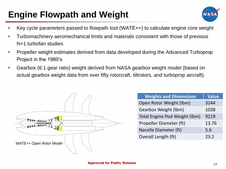
Engine Flowpath and Weight
• Key cycle parameters passed to flowpath tool (WATE++) to calculate engine core weight
• Turbomachinery aeromechanical limits and materials consistent with those of previous
N+1 turbofan studies
• Propeller weight estimates derived from data developed during the Advanced Turboprop
Project in the 1980’s
• Gearbox (6:1 gear ratio) weight derived from NASA gearbox weight model (based on
actual gearbox weight data from over fifty rotorcraft, tiltrotors, and turboprop aircraft).
WATE++ Open Rotor Model
Weights and Dimensions Value
Open Rotor Weight (lbm) 3244
Gearbox Weight (lbm) 1028
Total Engine Pod Weight (lbm) 9219
Propeller Diameter (ft) 13.76
Nacelle Diameter (ft) 5.6
Overall Length (ft) 23.2
15 Approved for Public Release
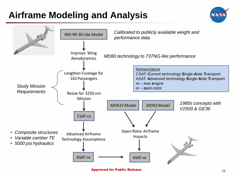
Airframe Modeling and Analysis
MD-90-30 Like Model
Improve Wing Aerodynamics
Lengthen Fuselage for 162 Passengers
CSAT-re
Resize for 3250 nm Mission
MD92V Model MD92 Model
Open Rotor Airframe Impacts
Advanced Airframe Technology Assumptions
ASAT-re ASAT-or
Calibrated to publicly available weight and
performance data
MD80 technology to 737NG-like performance
Study Mission
Requirements
• Composite structures
• Variable camber TE
• 5000 psi hydraulics
1980s concepts with
V2500 & GE36
Nomenclature
CSAT: Current technology Single-Aisle Transport
ASAT: Advanced technology Single-Aisle Transport
re – rear engine
or – open rotor
16 Approved for Public Release
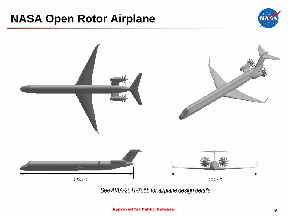
NASA Open Rotor Airplane
143.9 ft 111.7 ft
See AIAA-2011-7058 for airplane design details
17 Approved for Public Release
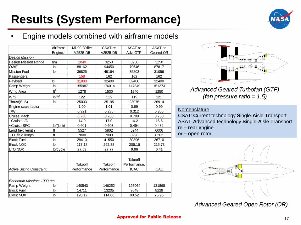
Airframe: MD90-30like CSAT-re ASAT-re ASAT-or
Engine: V2525-D5 V2525-D5 Adv. GTF Geared OR
Design Mission Range nm 2040 3250 3250 3250
OWE lb 88162 94450 79646 87817
Mission Fuel lb 36825 49164 35803 31056
Passengers 158 162 162 162
Payload lb 31000 32400 32400 32400
Ramp Weight lb 155987 176014 147849 151273
Wing Area ft2
1278 1530 1240 1250
W/S lb/ft2 122 115 119 121
Thrust(SLS) lb 25033 25195 23075 26914
Engine scale factor 1.00 1.01 0.99 0.99
T/W 0.321 0.286 0.312 0.356
Cruise Mach 0.760 0.780 0.780 0.780
~Cruise L/D 14.0 17.0 16.2 16.6
~Cruise SFC lb/(lb-h) 0.601 0.603 0.494 0.432
Land field length ft 5527 5802 5944 6006
T.O. field length ft 7000 7000 6996 6262
Block Fuel lb 29410 41550 30396 26710
Block NOX lb 217.18 292.38 205.16 215.73
LTO NOX lb/cycle 27.59 27.77 9.96 6.41
Active Sizing Constraint
Takeoff
Performance
Takeoff
Performance
Takeoff
Performance,
ICAC ICAC
Ramp Weight lb 140543 146252 126064 131868
Block Fuel lb 14711 13205 9648 8229
Block NOX lb 120.17 114.86 90.52 75.95
Design Mission:
Economic Mission: 1000 nm,
Results (System Performance)
• Engine models combined with airframe models
Nomenclature
CSAT: Current technology Single-Aisle Transport
ASAT: Advanced technology Single-Aisle Transport
re – rear engine
or – open rotor
Advanced Geared Turbofan (GTF)
(fan pressure ratio = 1.5)
Advanced Geared Open Rotor (OR)
18 Approved for Public Release
0
0.1
0.2
0.3
0.4
0.5
0.6
0.7
0.8
0.9
1
1.1
1.2
Operating Empty Weight
Gross Weight Block Fuel Total NOx LTO NOx
Re
lati
ve
Va
lue
s
Adv. Geared Turbofan Geared Open Rotor
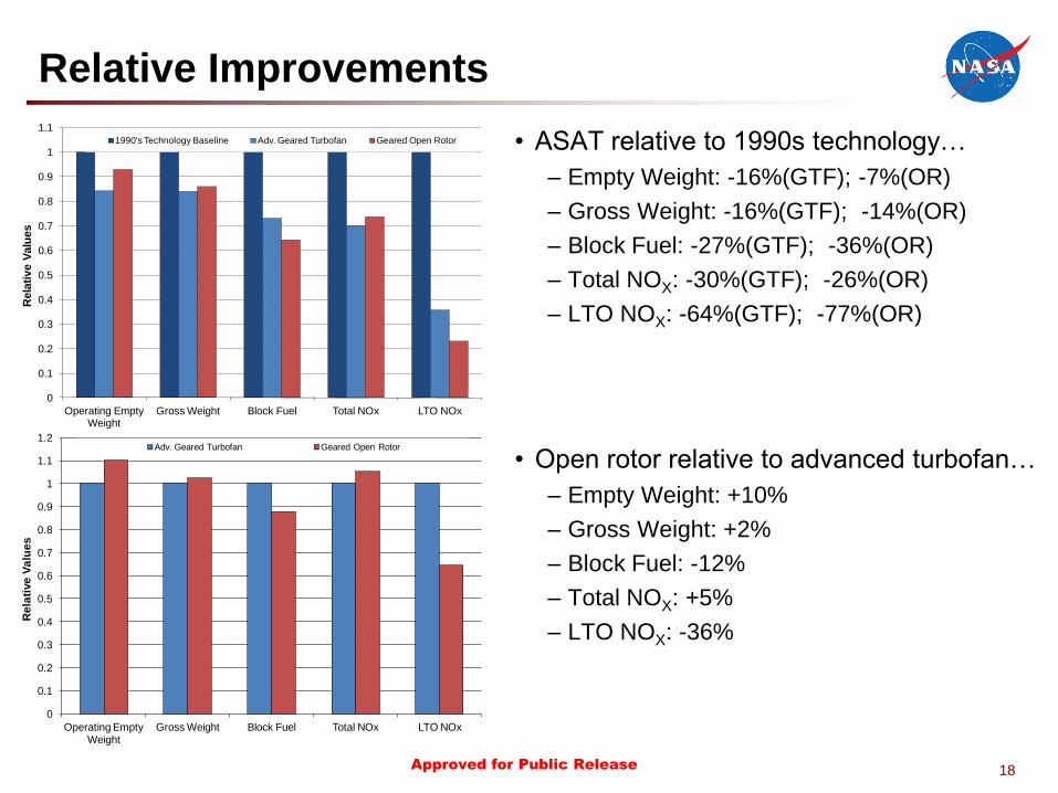
Relative Improvements
0
0.1
0.2
0.3
0.4
0.5
0.6
0.7
0.8
0.9
1
1.1
Operating Empty Weight
Gross Weight Block Fuel Total NOx LTO NOx
Rela
tive V
alu
es
1990's Technology Baseline Adv. Geared Turbofan Geared Open Rotor • ASAT relative to 1990s technology…
– Empty Weight: -16%(GTF); -7%(OR)
– Gross Weight: -16%(GTF); -14%(OR)
– Block Fuel: -27%(GTF); -36%(OR)
– Total NOX: -30%(GTF); -26%(OR)
– LTO NOX: -64%(GTF); -77%(OR)
• Open rotor relative to advanced turbofan…
– Empty Weight: +10%
– Gross Weight: +2%
– Block Fuel: -12%
– Total NOX: +5%
– LTO NOX: -36%
19 Approved for Public Release
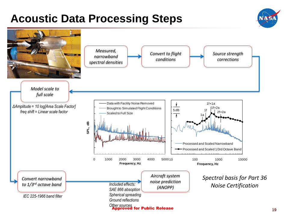
Acoustic Data Processing Steps
19
70
80
90
100
110
120
130
140
150
10 100 1000 10000S
PL
, d
BFrequency, Hz
Processed and Scaled Narrowband
Processed and Scaled 1/3rd Octave Band
1a
1f
1f+1a
1f+2a
2f+2a5 dB
70
80
90
100
110
120
130
140
150
0 1000 2000 3000 4000 5000
SP
L, d
B
Frequency, Hz
Data with Facility Noise Removed
Brought to Simulated Flight Conditions
Scaled to Full Size
Measured, narrowband
spectral densities
Convert to flight conditions
Source strength corrections
Model scale to full scale
Convert narrowband to 1/3rd octave band Included effects:
SAE 866 absoption
Spherical spreading
Ground reflections
Other sources
Aircraft system noise prediction
(ANOPP)
IEC 225-1966 band filter
ΔAmplitude = 10 log[Area Scale Factor]
freq shift = Linear scale factor
Spectral basis for Part 36 Noise Certification

20 Approved for Public Release
Part 36 Noise Certification
• Aircraft Noise Prediction Program (ANOPP)
• Source noise modeling: User-supplied
• Trajectory simulation
• Spectra propagation (spreading, atmospheric and lateral attenuation, ground effects, reflections)
• Frequency and Noy-scale integration
• Tonal content penalties
• Ground observer noise-time history
Noise certification points:
- Lateral (sideline)
- Flyover (with cutback)
- Approach 2000 m
(6562 ft)
Flyover
Reference
Lateral
(Sideline)
Reference
Approach
Reference
6500 m
(21 325 ft)
450 m
(1476 ft)
Time integration to Effective
Perceived Noise Level
Ob
serv
er
PN
LT
(P
Nd
B)
Observer Time (s)
75
80
85
90
95
100
-10 -5 0 5 10
Lateral Location

21 Approved for Public Release
Trajectory Modeling
• Open rotor propulsion system
and airplane performance
modeled
• Detailed takeoff and landing
trajectory analysis using Flight
Optimization System
performance code
0.0
0.5
1.0
1.5
2.0
2.5
-15 -10 -5 0 5 10 15 20 25 30
Alt
itu
de
, 1
00
0 ft
AF
E
Distance from Brake Release, 1000 ft
0
50
100
150
200
250
-15 -10 -5 0 5 10 15 20 25 30
Tru
e A
irs
pe
ed
, k
tas
Distance from Brake Release, 1000 ft
394 ft
1000 ft
2050 ft
137
178 180
0
5
10
15
20
25
30
-15 -10 -5 0 5 10 15 20 25 30
Ne
t T
hru
st
pe
r E
ng
ine
, 1
00
0 lb
Distance from Brake Release, 1000 ft
5780 lb
18070 lb
11270 lb
22 Approved for Public Release
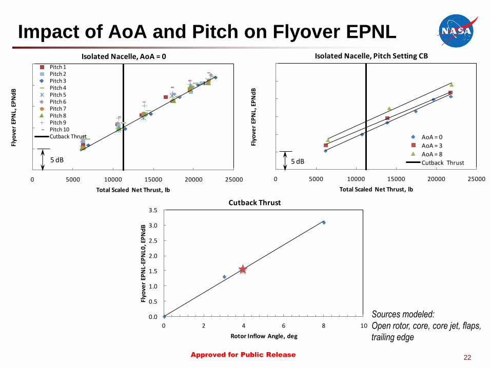
0.0
0.5
1.0
1.5
2.0
2.5
3.0
3.5
0 2 4 6 8 10
Flyo
ver
EPN
L-EP
NL0
, EP
Nd
B
Rotor Inflow Angle, deg
Cutback Thrust
Impact of AoA and Pitch on Flyover EPNL
Sources modeled:
Open rotor, core, core jet, flaps,
trailing edge
70
75
80
85
90
95
0 5000 10000 15000 20000 25000
Flyo
ver
EPN
L, E
PN
dB
Total Scaled Net Thrust, lb
Isolated Nacelle, AoA = 0Pitch 1Pitch 2Pitch 3Pitch 4Pitch 5Pitch 6Pitch 7Pitch 8Pitch 9Pitch 10Cutback Thrust
5 dB
70
75
80
85
90
95
100
0 5000 10000 15000 20000 25000
Flyo
ver
EPN
L, E
PN
dB
Total Scaled Net Thrust, lb
Isolated Nacelle, Pitch Setting CB
AoA = 0
AoA = 3
AoA = 8
Cutback Thrust5 dB
23 Approved for Public Release
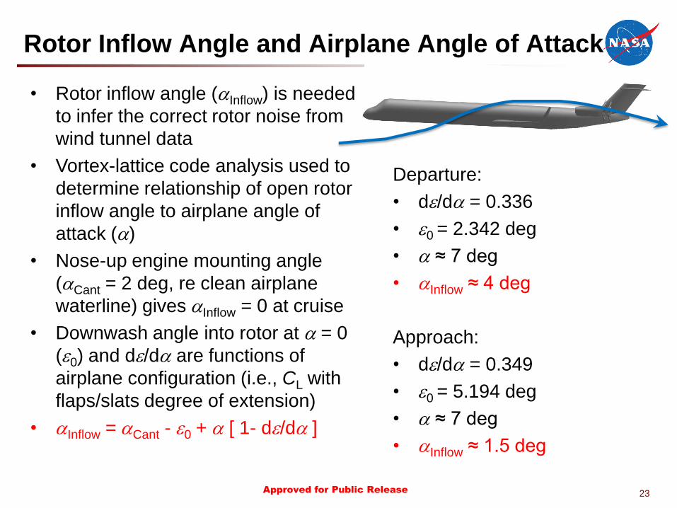
Rotor Inflow Angle and Airplane Angle of Attack
Departure:
• de/da = 0.336
• e0 = 2.342 deg
• a ≈ 7 deg
• aInflow ≈ 4 deg
Approach:
• de/da = 0.349
• e0 = 5.194 deg
• a ≈ 7 deg
• aInflow ≈ 1.5 deg
• Rotor inflow angle (aInflow) is needed
to infer the correct rotor noise from
wind tunnel data
• Vortex-lattice code analysis used to
determine relationship of open rotor
inflow angle to airplane angle of
attack (a)
• Nose-up engine mounting angle
(aCant = 2 deg, re clean airplane
waterline) gives aInflow = 0 at cruise
• Downwash angle into rotor at a = 0
(e0) and de/da are functions of
airplane configuration (i.e., CL with
flaps/slats degree of extension)
• aInflow = aCant - e0 + a [ 1- de/da ]
24 Approved for Public Release
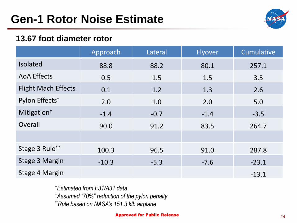
Gen-1 Rotor Noise Estimate
†Estimated from F31/A31 data ‡Assumed “70%” reduction of the pylon penalty **Rule based on NASA’s 151.3 klb airplane
Approach Lateral Flyover Cumulative
Isolated 88.8 88.2 80.1 257.1
AoA Effects 0.5 1.5 1.5 3.5
Flight Mach Effects 0.1 1.2 1.3 2.6
Pylon Effects† 2.0 1.0 2.0 5.0
Mitigation‡ -1.4 -0.7 -1.4 -3.5
Overall 90.0 91.2 83.5 264.7
Stage 3 Rule** 100.3 96.5 91.0 287.8
Stage 3 Margin -10.3 -5.3 -7.6 -23.1
Stage 4 Margin -13.1
13.67 foot diameter rotor
25 Approved for Public Release
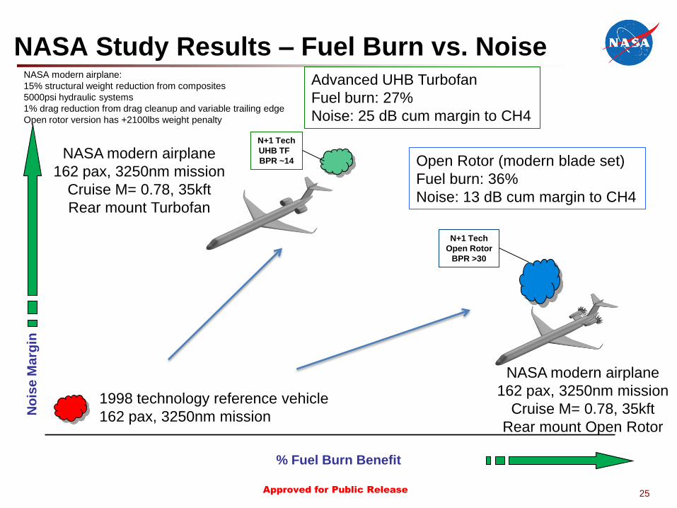
NASA Study Results – Fuel Burn vs. Noise
% Fuel Burn Benefit
No
ise M
arg
in
N+1 Tech
Open Rotor
BPR >30
N+1 Tech
UHB TF
BPR ~14
Advanced UHB Turbofan
Fuel burn: 27%
Noise: 25 dB cum margin to CH4
Open Rotor (modern blade set)
Fuel burn: 36%
Noise: 13 dB cum margin to CH4
NASA modern airplane
162 pax, 3250nm mission
Cruise M= 0.78, 35kft
Rear mount Turbofan
NASA modern airplane
162 pax, 3250nm mission
Cruise M= 0.78, 35kft
Rear mount Open Rotor
NASA modern airplane:
15% structural weight reduction from composites
5000psi hydraulic systems
1% drag reduction from drag cleanup and variable trailing edge
Open rotor version has +2100lbs weight penalty
1998 technology reference vehicle
162 pax, 3250nm mission
26 Approved for Public Release
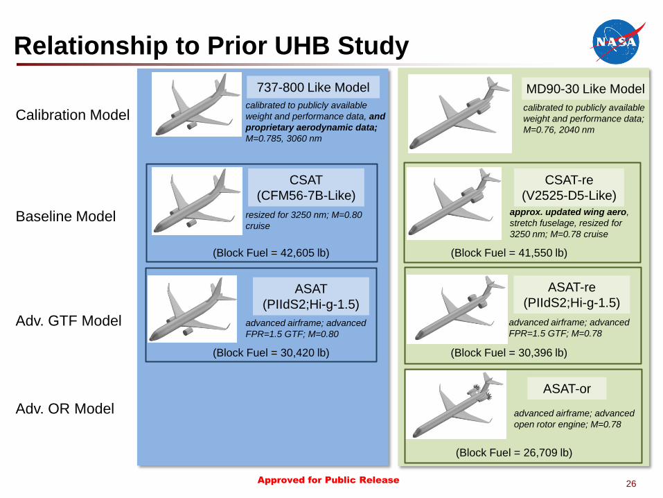
Relationship to Prior UHB Study
MD90-30 Like Model
calibrated to publicly available
weight and performance data;
M=0.76, 2040 nm
CSAT-re
(V2525-D5-Like)
approx. updated wing aero,
stretch fuselage, resized for
3250 nm; M=0.78 cruise
(Block Fuel = 41,550 lb)
advanced airframe; advanced
FPR=1.5 GTF; M=0.78
(Block Fuel = 30,396 lb)
ASAT-or
advanced airframe; advanced
open rotor engine; M=0.78
(Block Fuel = 26,709 lb)
737-800 Like Model
calibrated to publicly available
weight and performance data, and
proprietary aerodynamic data;
M=0.785, 3060 nm
CSAT
(CFM56-7B-Like)
resized for 3250 nm; M=0.80
cruise
(Block Fuel = 42,605 lb)
ASAT
(PIIdS2;Hi-g-1.5)
advanced airframe; advanced
FPR=1.5 GTF; M=0.80
(Block Fuel = 30,420 lb)
Calibration Model
Baseline Model
Adv. GTF Model
Adv. OR Model
ASAT-re
(PIIdS2;Hi-g-1.5)

Your Title Here 27