Embed Size (px)
Citation preview
DOE/NASA/20320-68 NASA TM-87166 NASA-TM-87166
ICj<26blJ{)13Db
Summary of Tower Designs for large Horizontal A}(is Wind Turbines
G.R. Frederick University of Toledo
and
J.M. Savino National Aeronautics and Space Administration Lewis Research Center
Work performed for
U.S. DEPARTMENT OF ENERGY Conservation and Renewable Energy . Wind/Ocean Technology Division .. '.:.: :, ::
IIIIIIIIIIIIWDMIIIIIMIIIIIWIIDI . F:' G ;<i;.:!p~~. NF01487 . .._L ..• r, __ ,_· .. ·.·AII~l:.JJit.,~
Prepared for Energy-Source Technology Conference and Exhibition sponsored by American Society of Mechanical Engineers New Orleans, Louisiana, February 23-27, 1986
https://ntrs.nasa.gov/search.jsp?R=19860009306 2018-05-21T00:52:28+00:00Z
DISCLAIMER
This report was prepared as an account of work sponsored by an agency of the United States Government. Neither the United States Government nor any agency thereof, nor any of their employees, makes any warranty, express or implied, or assumes any legal liability or responsibility for the accuracy, completeness, or usefulness of any information, apparatus, product, or process disclosed, or represents that its use would not infringe privately owned rights. Reference herein to any specific commercial product, process, or service by trade name, trademark, manufacturer, or otherwise, does not necessarily constitute or imply its endorsement, recommendation, or favoring by the United States Government or any agency thereof. The views and opinions of authors expressed herein do not necessarily state or reflect those of the United States Government or any agency thereof.
Printed in the United States of America
Available from National Technical Information Service U.S. Department of Commerce 5285 Port Royal Road Springfield, VA 22161
NTIS price codes1 Printed copy: A02 Microfiche copy: A01
1Codes are used for priCing all publications. The code is determined by the number of pages in the publication. Information pertaining to the pricing codes can be found in the current issues of the following publications, which are generally available in most libraries: Energy Research Abstracts (ERA); Government Reports Announcements and Index (GRA and I); Scientific and Technical Abstract Reports (STAR); and publication, NTIS-PR-360 available from NTIS at the above address.
DOE/NASA/20320-68 NASA TM-87166
Summary of Tower Designs for Large Horizontal Axis Wind. Turbines
G.R. Frederick University of Toledo Toledo, Ohio 43606
and
J.M. Savino National Aeronautics and Space Administration Lewis Research Center Cleveland, Ohio 44135
Work performed for U.S. DEPARTMENT OF ENERGY Conservation and Renewable Energy Wind/Ocean Technology Division Washington, D.C. 20545 Under Interagency Agreement DE-AI01-76ET20320
Prepared for Energy-Source Technology Conference and Exhibition sponsored by American Society of Mechanical Engineers New Orleans, Louisiana, February 23-27, 1986
SUMMARY OF TOWER DESIGNS FOR LARGE HORIZONTAL AXIS WINO TURBINES
G.R. Frederick The University of Toledo
Toledo, Ohio
and
J.M. Savino National Aeronautics and Space Administration
Lewis Research Center Cleveland, Ohio 44135
SUMMARY
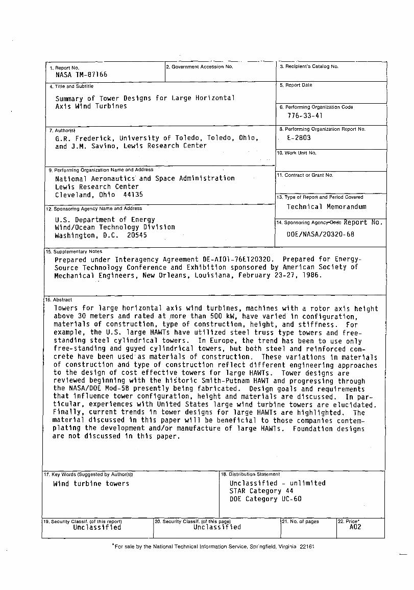
Towers for large horizontal axis wind turbines (machines with a rotor axis above 30 meters and rated at more than 500 kW) have varied in configuration, materials of construction, type of construction, height, and stiffness. For example, the U.S. large HAWTs have utilized steel truss type towers and freestanding steel cylindrical towers. In Europe, the trend has been to use only free-standing and guyed cylindrical towers, but both steel and reinforced concrete have been used as materials of construction. These variations in materials of construction and type of construction reflect different engineering approaches to the design of cost effective towers for large HAWTs.
Tower designs are reviewed beginning with the historic Smith-Putnam HAWT and progressing through the NASA/DOE Mod-5B presently being fabricated. Design goals and requirements that influence tower configuration, height and materials are discussed. In particular, experiences with United States large wind turbine towers are elucidated. Finally, current trends in tower designs for large HAWTs are highlighted. The material discussed in this paper will be beneficial to those companies contemplating the development and/or manufacture of large HAWTs. Foundation designs are not discussed in this paper.
INTRODUCTION
Towers for large horizontal axis wind turbines (LHAWTs) have varied in configuration, materials of construction, height, and stiffness. In this paper, a LHAWT is defined to be rated at 500 kW or more and to have a hub height above 30 meters. In the U.S., towers ranged in type from the stiff four leg steel truss tower to the rather flexible 12 sided free-standing cylinder (ref. 1). In Europe, on the other hand, LHAWT towers of the guyed cylinder type have been used in addition to the free-standing cylinder (ref. 2). By way of contrast, U.S. large wind turbine towers have been made of steel whereas in Europe reinforced concrete as well as steel has been a favored material.
It is not immediately obvious why such an array of tower configurations and materials of construction exists and whether any trends exist. The purposes of this brief paper are to (a) briefly discuss the important factors such as the goals, requirements, and loads which most influence the tower designs, (b) outline the general design approach, (c) list and describe in one article the towers which have been built for LHAWTs and most of those towers which, in
1985, have been designed and/or are under construction in the United states and Europe, and (d) point out the direction in which tower designs appear to be heading. The material presented herein is for the benefit of those persons and companies that are interested in the design and/or manufacture of support towers for LHAWTs. The foundation designs for the towers are not discussed because of space restrictions.
GOALS AND REQUIREMENTS
The primary requisite and goal for a wind turbine is that it be capable of producing electrical energy at a cost competitive rate. This implies that each major component of a wind turbine system be designed to be cost effective, including the tower. To achieve the goal of a cost effective tower requires that the designer strive to minimize fabrication, shipping, erection, and maintenance costs while at the same time achieving aesthetic and environmental acceptability. In addition to meeting these goals, the tower must also satisfy a number of important technical requirements.
The primary technical requirement for a LHAWT tower is that it support the rotor and the nacelle structure which contains the power train and auxiliary equipment. A second important requirement is that the tower safely withstand all of the loads imposed upon it by the wind and the environment during its service life, which is 20 to 30 years depending on the time chosen over which to amortize the wind turbine. In meeting this second requirement the tower characteristics, such as its natural frequency, shall not adversely affect the service life of other system components.
DESIGN LOADS
The primary loads and conditions that influence the design of a tower are those forces transmitted from the rotor and nacelle, and those imposed directly on the tower by (a) the infrequent extreme winds which can be as high as 50 to 70 mps (115 to 160 mph) depending upon the site; (b) the most frequent winds encountered under normal operating conditions (in the range from about 5 to 25 mps); (c) certain environmental conditions such as ice and snow accumulation and earthquakes; and (d) emergency conditions associated with equipment malfunction (refs. 3 to 6).
The extreme wind is the maximum wind speed that is expected at the site during the service life of the wind turbine. For design purposes it is conservatively assumed that this wind is steady, the machine is not operating, and the rotor blades are flat to the wind. The tower forces due to the extreme wind are usually the critical loads that significantly influence the tower design.
Under normal operating conditions, the tower is subjected to a combination of direct wind forces and dynamically induced forces. These include dynamically induced forces encountered during startup and shutdown operations. During normal operation the winds are generally nonuniform and unsteady. Such winds generate unsteady forces on the rotor blades which are transmitted to the tower and, to a lesser extent, on the tower directly. These unsteady forces during startup, power generation, and shutdown can result in fatigue damage and, perhaps, failure. Therefore, to ensure that the tower will not fail in
2
fatigue, it is necessary to know the unsteady characteristics of the wind and to properly include their effects in the design.
Another source of wind-induced excitation is the vortices that peel off the leeward side of a cylindrical tower. These vortices are periodic and induce oscillatory forces on the tower that can excite it if the-tower and vortex shedding frequencies are in resonance.
The more important emergency load cases are those resulting from (a) sudden loss of the generator load, or (b) unbalanced rotor forces caused by a malfunction of a rotor control element such as a pitch actuator. These types of loads are infrequent, but because they can be large, they must be included in the tower design. The loss of an entire blade is not usually an emergency load case for LHAWTs designed in the United states. For some LHAWTs designed in other countries, such as Sweden, loss of an entire blade is an emergency load case.
In addition to forces induced by the wind and turbine operations (mentioned above), the effects of low temperature and moisture must be considered. Very low temperatures, below -31°F, are known to affect the fracture toughness of steel. Moisture, particularly in a salt air environment, can lead to excessive corrosion which can shorten the tower life if the tower is not protected against it.
Finally, the tower design must take into consideration the forces on the tower during earthquakes, handling, transportation, and field assembly. While these forces are not usually critical to the design of the tower, their effects must be assessed.
DESIGN APPROACH
The design of a support tower may be begun by superimposing the extreme wind loads upon the dead loads associated with the system. The extreme wind loads are usually calculated with the blades parked and flat to the wind. All wind azimuths with respect to the axis of rotation must be considered to ensure that the critical case has been used. For design of the tower, this is expected to occur with the rotor located downwind of the tower. For this orientation, the tower bending moment due to the wind will directly add to the dead load bending moments associated with the nacelle and rotor. The tower is then sized to resist these loads. At this conceptual design stage, various tower configurations may be considered. As soon as a design can be shown to be unacceptable (not economical, not associated with ease of construction, etc.), it is rejected and dropped from the list of possible acceptable designs.
Those designs remaining on the list are then checked for the various combinations associated with normal operating conditions, environment conditions and emergency conditions. The appropriate wind characteristics including wind shear, surface roughness, gusting and turbulence must be included when calculating the associated loads. Since these loads are time-varying, it is necessary to perform fatigue analyses for the various loads to determine whether the designs are adequate. The natural frequencies of vibration of the wind turbine system also must be determined for the various tower configurations. Designs that are inadequate are then modified or rejected. Designs may be rejected for factors such as tower shadow effects, shipping considerations,
3
field assembly considerations, foundation design considerations, nolse, aesthetics, etc.
W1nd-1nduced v1bration of the tower must also be investigated. In steady w1nd conditions vort1ces are alternately shed from the sldes of cyllndr1cal structures wh1ch can lead to swaying motions. If the vortex shedding frequency colncldes with a natural frequency of vibration, resonance will occur. Th1s cond1tion must be checked for the complete wind turbine structure, and for the tower alone. If the tower alone 1s associated w1th resonance, temporary strakes {he11cal str1ps} can be 1nstalled on the outs1de of the tower dur1ng construction until the equipment is attached at the top of the tower to break up the vort1ces.
F1nally, a cost analys1s of the complete LHAWT system 1s performed for all designs which have not been rejected. In these analyses, the total costs assoc1ated with each tower design must be considered. The total cost includes a consideration of fabricat10n costs, shipping costs, erect10n costs and ma1ntenance costs. The preferred tower des1gn is that wh1ch sat1sf1es all the goals and requ1rements, and which 1s assoc1ated w1th the min1mum cost. F1nal des1gn of the tower is then completed for this tower.
u.s. LHAWT TOWER DEVELOPMENT
The first megawatt LHAWT constructed anywhere was the 1250 kW Smith-Putnam machine (ref. 7). It was built in 1940 and operated near Rutland, Vermont from 1941 to 1945. Since 1975, under sponsorsh1p of the u.S. Department of Energy {DOE} and under NASA management, f1ve 1ntermed1ate s1ze and s1x megawatt size HAWTs have been built and operated: the 100 kW Mod-O; four 200 kW Mod-OAls; the 2000 kW Mod-l; and f1ve 2500 kW Mod-2 ls {ref. 2}. Another mult1megawatt HAWT, the 4000 kW WTS-4, was bu1lt for the u.S. Department of the Interior by the Ham1lton-Standard Company. Only the Mod-O, four of the Mod-2 I s, and the WTS-4 remained in operation as of July 1985. In table I are summarized the princ1pal features of the above-ment1oned machines with emphasis on the tower character1st1cs. {The Mod-O and Mod-OA mach1nes, though intermed1ate in size, are included to provide weight versus height data for truss type towers at the lower end of the weight and height scales.}
Of the HAWTs ment10ned above, seven were constructed with four-leg truss type towers: the Sm1th-Putnam mach1ne, the Mod-O, Mod-OAls, and the Mod-l. The Mod-l truss type tower 1s shown 1n figure 1. Subsequently, the Mod-O truss tower was replaced w1th a 12-s1ded cy11nder braced with 4 struts. {This was done to study the dynam1cs of a wind turbine system with a more flex1ble tower.} One LHAWT has a slightly tapered, steel 12-sided cylindrical tower: the WTS-4. This tower was made of brake-formed segments which were welded together and is shown in f1gure 2. The rest, the f1ve Mod-2 I s, had freestanding untapered steel c1rcular towers with steel conical bases as shown in figure 3.
The Mod-O and Mod-OA were considered to be experimental wind turbines. They were the first of the1r k1nd to be bu11t in the present era. The primary objective of these was to ga1n exper1ence and acquire a data base needed for develop1ng cost effective mach1nes. To ensure successful and safe operation, the Mod-O and Mod-OA towers, as well as the other components, were conservatively designed. Each of these wlnd turbines and the Mod-l had a rotor with
4
two blades r1g1dly attached to the hub wh1ch, 1n turn, was r1g1dly attached to the low speed shaft; that is, the rotors were not teetered. furthermore, the rotors were downwind of the towers. In this configurat1on, and 1n a gradient wind field, the rotor imparts h1gh bending and high torsional moments to the tower at the dominant frequency equal to the blade passing frequency (two per revolut10n for two blade rotors). At the t1me the Hod-O and Hod-OA mach1nes were des1gned, computer codes w1th wh1ch to analyze the1r dynamic behavior were not read11y available. To ensure the tower did not have a first bending and a f1rst tors10nal frequency equal or close to two per revolution, the truss tower was chosen and designed to have its first bending and torsional frequencies above this value. The result was that the Hod-O and Mod-OA towers were quite stiff; as a consequence they also were heavy and expensive.
The Smith-Putnam wind turbine was the end result of many design and cost stud1es aimed at developing the HAWT as a cost-effective source of renewable power. The hub height selected was 36 m. Its four-leg truss type tower was cons1dered to be a cost effective tower concept at that t1me. It was built us1ng standard structural elements such as channels, I-beams, and angles. (The weight was not ava1lable in any publ1cat10ns.)
The Mod-l was also des1gned with cost effect1veness as a goal. As 1n the Sm1th-Putnam project, the Mod-l was the end product of a conceptual design and cost study a1med at ident1fying the most prom1s1ng size and configuration of future cost effect1ve wind turbines (ref. 8). Accordingly, a stiff truss type tower was chosen and designed. However, experience with fabrication and assembly of the Mod-l showed that the truss concept was not cost effective for megawatt size LHAWTs. A follow-on design improvement and cost reduction study 1nd1cated that an upw1nd, teetered, two-blade rotor atop a somewhat flex1ble cy11ndr1cal tower would result in lower tower loads and a lower cost megawatt s1ze LHAWT concept. Additionally, the use of a more flexible tower would be assoc1ated w1th the magnitudes of forces exerted on other components of the LHAWT being reduced. These f1nd1ngs led to the 1nclus1on of the teetered rotor and the more flexible cylindr1cal tower 1nto the design of all subsequent U.S. LHAWTs which are operat1ng, namely the Mod-2 l s and the WTS-4, and 1n the more recent des1gns that are being bu1lt, such as the Mod-56 and the Westinghouse 600 kW WWG-0600. The features of the Mod-SA, Mod-56 and the WWG-0600 are presented 1n table II. The Mod-SA des1gn will not be built since the project was term1nated in late 1983.
The term1nology commonly used to descr1be the flex1b1l1ty of a LHAWT tower 1s soft-soft tower, soft tower, and st1ff tower. A soft-soft tower has its first bend1ng frequency of v1bration with equ1pment mounted on top at a value less than the frequency of rotor rotat10n. A soft tower has its first bend1ng frequency between one and N t1mes the frequency of rotor rotation where N 1s the number of blades. The st1ff tower has its first bending frequency at a value more than N times the frequency of rotor rotat10n. The Mod-2 l s and the Mod-56 were constructed/des1gned w1th soft towers. The only U.S. LHAWT constructed with a soft-soft tower was the WTS-4.
EUROPEAN LHAWT TOWER DEVELOPMENTS
F1ve exper1mental LHAWTs are in operation in Europe: the two 630 kW N1be A and 6 wind turbines in Denmark (ref. 9); the 3000 kW Haglarp and 2000 kW Nasudden machines in Sweden (ref. 10); and the 3000 kW Grow1an wind turbine in
5
West Germany (ref. 11). Eight have been recently designed, some of which are being built. Some of the principal features of these fifteen machines are given in tables I and II. (Several intermediate size HAWTs are included in table II to provide weight and height data for cylindrical towers at the lower end of the scale.)
Of the five wind turbines in operation, three (the Nibe A and B, and the Nasudden) have towers made of reinforced concrete that were constructed using the well developed sl1pforming technique. In fact, these appear to be the only concrete towers in Europe or the u.S. supporting LHAWTs. The Mag1arp tower is a free-standing untapered circular steel cylinder; whereas, the Grow1an is a guyed untapered steel cylinder, and appears to be the only guyed tower on a LHAWT anywhere. Concrete towers, as shown in figure 4, were chosen for the N1be A and B in part because reinforced concrete is widely used in large structures in Denmark and because such towers were used in many wind turbines that were built in the 1940's. In addition, reinforced concrete towers have been shown to be cost effective in Denmark (ref. 12). This is reflected in the use of reinforced concrete towers for the five new 750 kW LHAWTs now (1985) under construction.
The Maglarp and Nasudden LHAWTs utilized cylindrical towers each of a different material, steel and reinforced concrete, for the purposes of a comparative evaluation. An evaluation of these two wind turbine systems was completed in late 1984, and it was concluded that, when mass produced, both the Nasudden and Maglarp machines would produce electricity at a competitive rate (ref. 13). This suggests that both types of towers would be acceptable and therefore cost effective.
The experience with the Grow1an is not yet available. However, it may be correct to infer that guyed towers are not a preferred concept for megawatt size wind turbines since the latest West German megawatt design (the WEC-60) has a free-standing cylinder on a conical base (ref. 14).
When the new generation of European LHAWTs are reviewed (table II), it is clear that a free-standing cylinder, either tapered or untapered, with or without a conical base, is the preferred type of tower. All except the five Masnedo, the Orkney-60 and the WEC-60 machines will use steel as the material of construction. The Masnedo wind turbine towers are being constructed of reinforced concrete. The Orkney-60 LHAWT tower is a hybrid, as shown in figure 5: a reinforced concrete conical base with an inverted steel conical top. The WEC-60 LHAWT tower is also a hybrid: a steel cylinder on a conical reinforced concrete base. Here a concrete base was selected since the turbine is sited off-shore.
CURRENT TRENDS
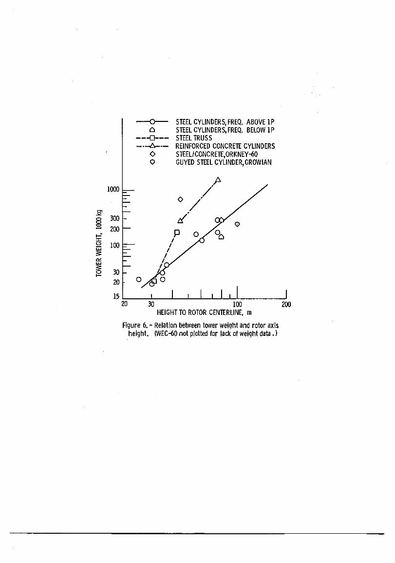
Some general trends can be discerned from an examination of the relation between tower weight and rotor axis height plotted in figure 6 using the data of tables I and II. In figure 6, the plotted points are grouped where possible according to tower type and/or construction materials. Some points are for towers that are unique; therefore, trends for these towers are not discernible. An analysis using only this relationship is admittedly a rather simple one because other factors such as the rotor diameter, and the tower
6
natural frequenc1es also 1nfluence the towerwe1ght. Nonetheless, some useful trends can be seen.
A 11ne drawn through the p01nts for the Mod-O, Mod-OA, and Mod-l truss towers has the steepest slope (we1ght increase w1th rotor he1ght). Only at small he1ghts does the truss tower appear to have a weight advantage w1th respect to other steel towers. S1nce the truss tower, for rotor he1ghts associated with LHAWTs, is heavy, it can be expected to be expensive and st1ff. Accordingly, the stiff steel truss tower is probably not an economical concept for a LHAWT.
A line drawn through the points represent1ng the various steel cylindrical towers has a much gentler slope. For rotor heights assoc1ated w1th LHAWTs they offer considerable weight sav1ngs w1th respect to steel truss towers. S1nce cy11ndr1cal towers offer a we1ght reduct10n and also have a smaller cross section than truss towers, they are more flex1ble. This attenuates the magn1tudes of the dynam1c forces acting on the var10us components of a LHAWT. It is concluded that a steel cylindrical tower is a cost effective concept for a LHAWT. This conclus10n is substant1ated by the fact that more steel cy11ndr1cal towers have been constructed to date than any other type of tower supporting a LHAWT.
The line drawn through the points representing the var10us free-stand1ng steel cy11ndrical towers 1n f1gure 6 applies only to those with a natural bending frequency above one per revolut10n (lP), or soft towers. The only other free-stand1ng steel cy11ndrical towers are those of the WTS-3 and WTS-4, which are a soft-soft towers. Th1s line 1nd1cates that the tower weight in kilograms increases approx1mately as the rotor ax1s height in meters to the 2.85 power.
The 11ne drawn through the points representing the various free-standing reinforced concrete cylindrical towers closely parallels that drawn through the points representing free-standing steel cy11ndr1cal towers. This line 1s defined by only two p01nts - the N1be A and Band Masnedo towers (which all have the same characteristics) and the Nasudden tower. These towers are regarded as cost effective by their designers (refs. 12 and 13). S1nce these two lines are parallel, 1t 1s concluded that the most cost effect1ve tower is that utilizing the material that can be constructed and ma1nta1ned most economically. The construct10n cost per pound of reinforced concrete relative to structural steel 1s cons1derab1y less and may vary widely from site to site. Hence, the selection between free-standing reinforced concrete and freestanding steel cy11ndrical towers can not be made merely be comparing the plots in f1gure 6. The local unit construct1on costs must be included. Addit10nal operating and ma1ntenance items, such as paint1ng, must be cons1dered since two different materials are be1ng compared. From figure 6, it 1s concluded that free-standing reinforced concrete and free-stand1ng steel cylindr1cal towers offer the most prom1s1ng cost effective concepts for support towers for LHAWTs.
The other tower configurat10ns plotted in figure 6 are each un1que. As such, no trend of tower weight w1th rotor he1ght can be developed.
The WTS-3 and 4 towers are 1nteresting because of what they reveal about the effect of the natural frequency on tower weight. Both towers have a natural frequency below 1P: 0.35 Hz for the WTS-3 tower and 0.28 Hz for the WTS-4 tower (which is about 80 percent that of the WTS-3). A compar1son of the tower we1ghts shows that the we1ght of the WTS-4 tower is about one half of the WTS-3
7
tower weight. This comparison clearly demonstrates that a significant reduction in tower natural frequency results in a significant reduction of the tower weight. A comparison of the Mod-2 and Mod-5B, which are nearly identical configurations except for the rotor diameter and rated power, illustrates the effect of a change in rotor diameter and power plus increased design conservatism. These three factors drove the tower weight up by 40 percent.
Some comments can be made about the Orkney-60, Grow1an, and WEC-60 towers even though they are unique. The Orkney-60 has the same rotor axis height as the Nibe A and B, -and Masnedo machines, a much larger rotor area diameter, and a considerably heavier tower (2.55 times heavier). This larger weight probably reflects the effect of the larger rotor diameter and possibly a greater stiffness. The guyed tower of the Grow1an also has its first natural bending frequency below 1P. Even though its weight is not high in relation to its height, it was judged to be too expensive because of the costly guy cables (ref. 14); this may be one reason for the shorter steel cylindrical tower on the reinforced concrete base of the WEC-60.
CONCLUSIONS
Based upon the information available, it can be said that the general trend, with few exceptions, has been away from stiff towers toward flexible towers. The favored type today is the soft, free-standing cylindrical tower; some of which are on conic bases, some are tapered, and others are untapered. (Often a conic base is not used for structural considerations, but rather to provide space for a control room at the base of the tower.) The use of a soft tower eliminates the potential problems associated with the rotor passing through resonance as it accelerates to operating speed.
Favored materials of construction are both steel and reinforced concrete. Often the literature contained statements indicating that neither steel nor reinforced concrete offered a clear-cut cost advantage. The selection between these two materials is site-sensitive. The material chosen will depend upon unit costs associated with the materials and upon the local construction technology.
REFERENCES
1. Linscott, B.S., Perkins, P., and Dennett, J.T., "Large Horizontal-Axis Wind Turbines", NASA TM-83546, 1948.
2. Sixth Biennial Wind Energy Conference and Workshop, I.E. Vas, ed., American Solar Energy Society, Boulder, CO, 1983, pp. 59, 75.
3. Andersen, T.S. et a1, "Mod-OA 200KW Wind Turbine Generator Design and Analysis Report", AESD-TME-3052, Westinghouse Electric Corp., Pittsburgh, PA, Aug. 1980. (NASA CR-165128)
4. "Mod-l Wind Turbine Generator Analysis and Design Report", NASA CR-159495. 1979.
5. "Mod-2 Wind Turbine System Development Final Report", Vol. II: Detailed Report; NASA CR-168007, 1982.
8
6. "Mod-5A Wind Turbine Generator Program Design Report", Vol. III: Final Design and System Description, NASA CR-174736, 1984.
7. Putnam, P.C., Power from the Wind, Van Nostrand Reinhold Co., New York, 1948.
8. "Design Study of Wind T~rb1nes, 50KW to 3000KW for Electric utility Applications", Vol. 2, Analysis and Design, GE-SD-76SD4288-VOL-2, General Electric Company, Ph11ade1ph1a~ PA, Dec. 1976. (NASA CR-134935)
9. "The N1be Wind Turbines", a public information brochure by Ministry of Energy and The Electric utilities in Lyn~by~ Denmark, July 1980.
10. "The National Swedish Wind Energy Program", a public information brochure by The National Swedish Board for Energy Source Development, Stockholm, Sweden, 1982.
11. Hau, E., "Design of Growian Large Wind Energy Converter", Modern Power Systems, Vol. 1, No. 11, Dec. 1981, pp. 26-31.
12. Johnsen, F., E1kraft Power Co., Ltd., Ba11erup, Denmark; Private Communication, July 1985.
13. Engstrom, S., "Wind Energy Activitie~ inS~eden" Proceedings of the Delphi Workshop on Wind Energy Applications, 1985, Delphi, Greece, May 20-22, (to be published).
14. Hau, E., MAN, Kar1sfe1d, Federal Republic of Germany, Private Communication, 1985.
15. Boeing Aerospace Company Unpublished Contractor Design Documents, NASA, Cleveland, Ohio, 1985.
16. "Westinghouse Wind Turbine Generators; Technical Description of the WWG-0600 Wind Turbine", Report No. WT0009s, Westinghouse Electric Corporation, Pittsburgh, PA, July 1985.
17. "Howden Wind Generators, Specification Sheets", James Howden and Co. Ltd., Glasgow, Scotland, July 1985.
18. Bedford, L.A.W., Simpson, P.B., and Stevenson, W.G., "The Orkney 60 Metre Horizontal Axis Wind Turbine Generator - A Progress Report." Wind Energy Conversion 1985, P.J. Musgrove, ed., Cambridge University Press, Oxford, England, 1985, pp. 241-251.
19. Aer1talia, Societa Aerospaziale Italiana p.A., Rome, Italy, Private Communication, May 1985.
20. "Polenko Starts 300 kW Turbine Mass Production," Windirections, Vol. III, No.3, Dec. 1983, p. 17.
9
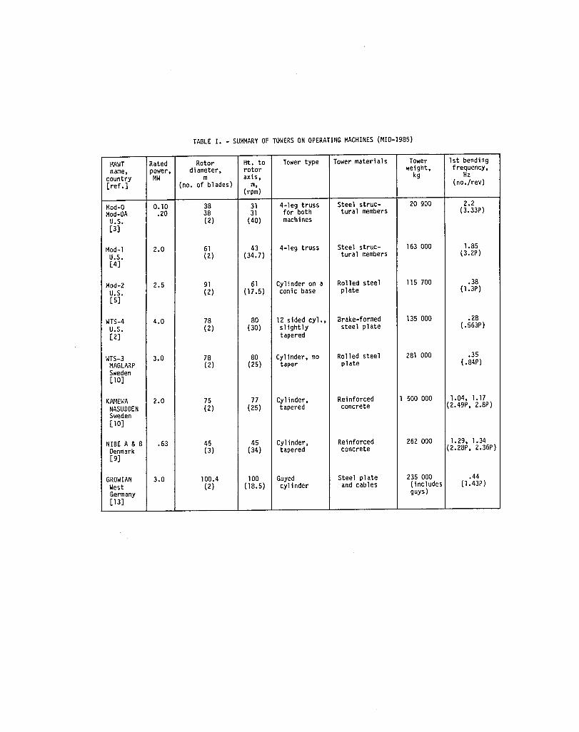
TABLE I. - SUMMARY OF TOWERS ON OPERATING MACHINES (MID-1985)
HAWT Rated Rotor Ht. to Tower type Tower materials Tower 1st bending name, power, diameter, rotor weight, frequency,
country MW m axis, kg Hz [ref. ] (no. of blades) m, (no./rev)
(rpm)
Mod-O 0.10 38 31 4-leg truss Steel struc- 20 900 2.2 Mod-OA .20 38 31 for both tural members (3.33P)
U.S. (2) (40) machines [3]
Mod-l 2.0 61 43 4-leg truss Steel struc- 163 000 1.85 U.S. (2) (34.7) tural members (3.2P) [4]
Mod-2 2.5 91 61 Cyl i nder on a Rolled steel 115 700 .38 U.S. (2) (17 .5) conic base plate (1.3P) [5]
WTS-4 4.0 78 80 12 sided cyl., Brake-formed 135 000 .28 U.S. (2) (30) sl ightly steel plate (.563P)
[2] tapered
WTS-3 3.0 78 80 Cylinder, no Rolled steel 281 000 .35 MAGLARP (2) (25) taper plate ( .84P) Sweden [10]
KAMEWA 2.0 75 77 Cyl inder, Reinforced 1 500 000 1.04, 1.17 NASUDDEN (2) (25) tapered concrete (2.49P, 2.8P) Sweden [10]
NIBE A & B .63 45 45 Cylinder, Reinforced 262 000 1.29, 1.34 Denmark (3) (34) tapered concrete (2.28P, 2.36P) [9]
GROW IAN 3.0 100.4 100 Guyed Steel plate 235 000 .44 West (2) (18.5) cyl inder and cables ( includes (1.43P) Germany guys) [13]
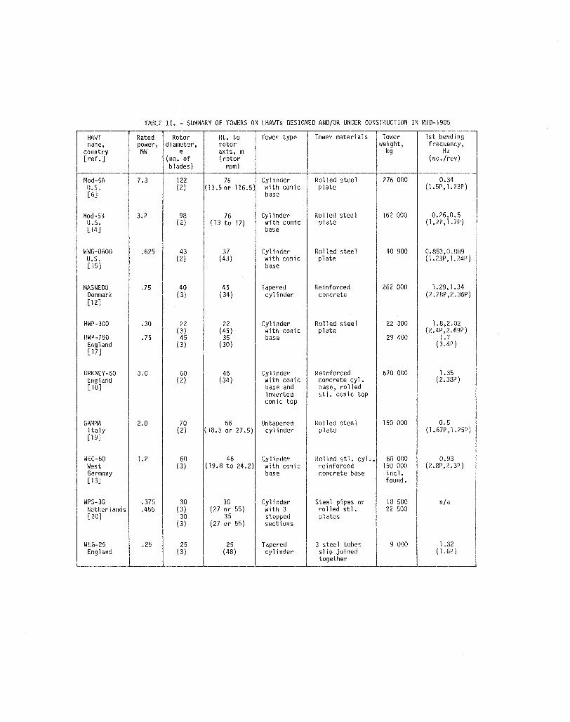
TABLE II. - SUMMARY OF TOWERS ON LHAWTs DESIGNED AND/OR UNDER CONSTRUCTION IN MID-1985
HAWT Rated Rotor Ht. to Tower type Tower materials Tower 1st bending name, power, diameter, rotor weight, frequency,
country MW m axis, m kg Hz [ref. ] (no. of (rotor (no./rev)
blades) rpm)
Mod-5A 7.3 122 76 Cylinder Rolled steel 276 000 0.34 U.S. (2) (13.5 or 116.5) with conic plate (1.5P,1.23P) [6] base
Mod-5B 3.2 98 76 Cyl inder Rolled steel 162 000 0.26,0.5 U.S. (2) (13 to 17) with conic plate (1.2P,1.7P) [14] base
WWG-0600 .625 43 37 Cyl inder Rolled steel 40 900 0.883,0.889 U.S. (2) (43) with conic plate (1.23P,1.24P) [15J base
MASNEDO .75 40 45 Tapered Reinforced 262 000 1.29,1.34 Denmark (3) (34) cylinder concrete (2.28P,2.36P) [12J
HWP-300 .30 22 22 Cylinder Rolled steel 22 300 1.8,2.02 (3) (45) with conic plate (2.4P,2.69P)
HWP-750 .75 45 35 base 29 400 1.7 England (3) (30) (3.4P) [17]
ORKNEY-60 3.0 60 45 Cylinder Reinforced 670 000 1.35 England (2) (34) with conic concrete cyl. (2.38P) [18] base and base, rolled
inverted st1. conic top conic top
GAMMA 2.0 70 56 Untapered Rolled steel 150 000 0.5 Italy (2) (18.3 or 27.5) cylinder plate (1.67P,1.25P) [19]
WEC-60 1.2 60 46 Cylinder Rolled stl. cyl., 60 000 0.93 West (3) (19.8 to 24.2) with conic reinforced 150 000 (2.8P ,2. 3P) Germany base concrete base incl. [ 13] found.
WPS-30 .375 30 30 Cy1 inder Steel pipes or 18 500 n/a Netherlands .455 (3) (27 or 55) with 3 rolled stl. 22 500 [20] 30 35 stepped plates
(3) (27 or 55) sections
WEG-25 .25 25 25 Tapered 3 steel tubes 9 000 1.32 England (3) (48) cyl inder slip joined ( 1.6P)
together
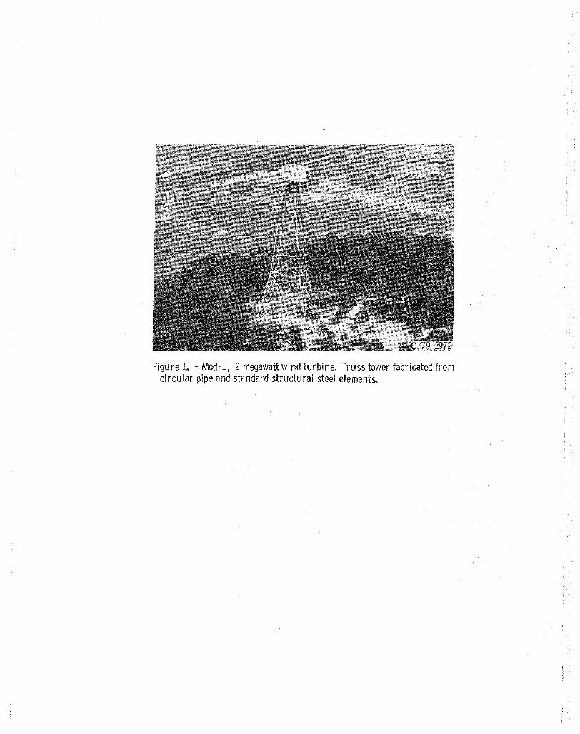
re 1. - Mod-I, 2 megawatt wind turbine. tower pipe and standard steel elements.

2. WTS 4 megawatt wind turbine. Tower is a 12-sided steel cyli slightly tapered.
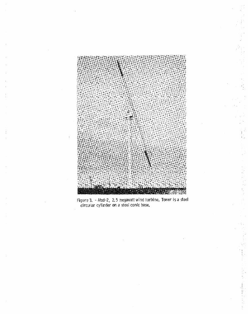
3. - Mod-2 v 2.5 megawatt wind turbine. Tower is a circu lar cylinder on a steel conic base.
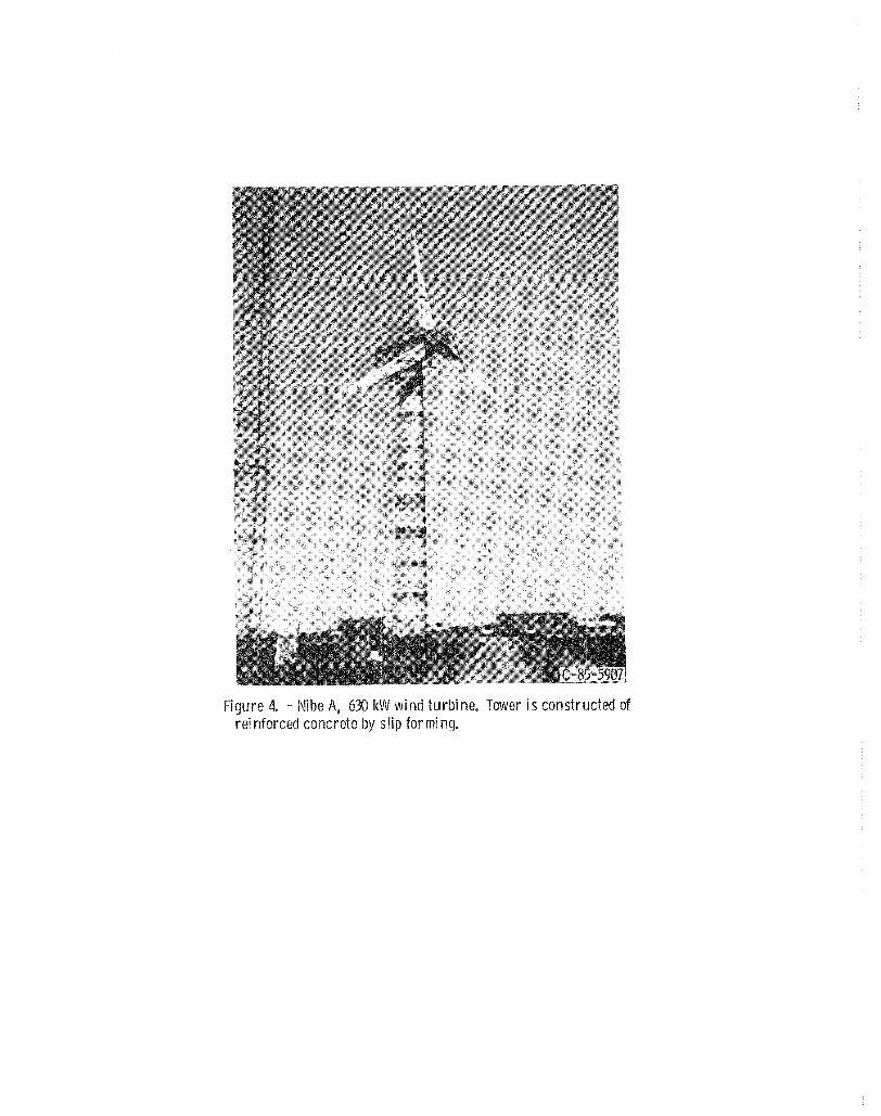
Figure 4. - Nibe A, 630 kW wi nd turbi nee Tow{~r is constructed of reinforced concrete by slip forming.
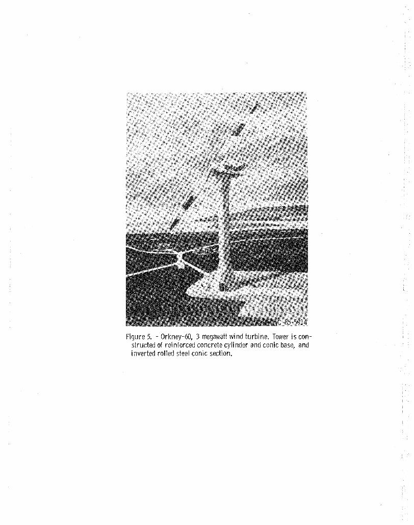
5. - Orkney-60, 3 meClaWcm wi turbine. Tower is con-structed of rei nforced cyli nder and conic base, and inverted rolled steel conic
1000
~
~ 300 § - 200 ..: :r: ~ 100 :: a::: L&.J
:: ~ 30
20
~ c:.
---0------l::.---
o o
STEEL CYLINDERS, FREQ. ABOVE 1P STEEL CYLINDERS, FREQ. BELOW 1P STEEL TRUSS REINFORCED CONCRETE CYLINDERS STEELICONCRETE,ORKNEY-60 GUYED STEEL CYLINDER, GROWIAN
o
15~ __ ~ __ ~ __ ~~~~~~ ______ ~ 20 30 100
HEIGHT TO ROTOR CENTERLINE, m
Figure 6. - Relation between tower weight and rotor axis height. (WEC-60 not plotted for lack of weight data. )
200
1. Report No. 2. Government Accession No.
NASA lM-87166 4. Title and Subtitle
Summary of Tower Designs for Large Horizontal Axis Wind Turbines
7. Author(s)
G.R. Frederick, University of Toledo, Toledo, Ohio, and J.M. Savino, Lewis Research Center
9. Performing Organization Name and Address
National Aeronautics and Space Administration Lewis Research Center Cleveland, Ohio 44135
12. Sponsoring Agency Name and Address
U.S. Department of Energy Wind/Ocean Technology Division Washington, D.C. 20545
15. Supplementary Notes
3. Recipient's Catalog No.
5. Report Date
6. Performing Organization Code
776-33-41
8. Performing Organization Report No.
E-2803
10. Work Unit No.
11. Contract or Grant No.
13. Type of Report and Period Covered
Technical Memorandum
14. Sponsoring Agenc~de Report No.
DOE/NASA/20320-68
Prepared under Interagency Agreement DE-AIOl-76E120320. Prepared for EnergySource Technology Conference and Exhibition sponsored by American Society of Mechanical Engineers, New Orleans, Louisiana, February 23-27, 1986.
16. Abstract
lowers for large horizontal axis wind turbines, machines with a rotor axis height above 30 meters and rated at more than 500 kW,have varied in configuration, materials of construction, type of construction, height, and stiffness. For example, the U.S. large HAWTs have utilized steel truss type towers and freestanding steel cylindrical towers. In Europe, the trend has been to use only free-standing and guyed cylindrical towers, but both steel and reinforced concrete have been used'as materials of construction. These variations in materials of construction and type of construction reflect different engineering approaches to the design of cost effective towers for large HAWTs. Tower designs are reviewed beginning with the historic Smith-Putnam HAWl and progressing through the NASA/DOE Mod-58 presently being fabricated. Design goals and requirements that influence tower configuration, height and materials are discussed. In particular, experiences with United States large wind turbine towers are elucidated. Finally, current trends in tower designs for large HAWls are highlighted. The material discussed in this paper will be beneficial to those companies contemplating the development and/or manufacture of large HAWls. Foundation designs are not discussed in this paper.
17. Key Words (Suggested by Author(s»
Wind turbine towers
19. Security Classif. (of this report) Unclassified
18. Distribution Statement
Unclassified - unlimited STAR Category 44 DOE Category UC-60
20. Security Classif. (of this page) Unclassified
21. No. of pages
* For sale by the National Technical Information Service, Springfield, Virginia 22161
22. Price· A02
End of Document