Embed Size (px)
Citation preview

SUMMARY OF THE NCHRP REPORT 350
CRASH TEST RESULTS FOR THE
CONNECTICUT TRUCK MOUNTED ATTENUATOR
Prepared by:
Dr. John F. Carney III
Dr. Charles E. Dougan
Eric C. Lohrey
June 1995
Report No.
2216—1-95—2
Research Project
SPR—2216
Dr. Charles E. Dougan
Director of Research and Materials
A Project in cooperation with the
U.S. Department of Transportation
Federal Highway Administration

ii
Technical Report Documentation Page
1.Report No. FHWA-CT-RD,2216-1-95-2
2. Government Accession No. 3. Recipients Catalog No. 2216-1-95-2
5. Report Date June 1995
4. Title and Subtitle Summary of the NCHRP Report 350 Crash Test Results for the Connecticut Truck Mounted Attenuator
6. Performing Organization Code SPR-2216
7. Author(s) John F. Carney,III, Charles E. Dougan, and Eric C. Lohrey
8. Performing Organization Report No. 2216-1-95-2
10. Work Unit No. (TRIS) 11. Contract or Grant No. CT-HPR Study No. 2216
9. Performing Organization Name and Address Connecticut Department of Transportation Division of Research 280 West Street, Rocky Hill, CT 06067-3502
13. Type of Report and Period Covered Interim October 1994 – January 1995
14. Sponsoring Agency Code FCP
12. Sponsoring Agency Name and Address Connecticut Department of Transportation Bureau of Engineering and Highway Operations 2800 Berlin Turnpike, Newington, CT 06131-7546
15. Supplementary Notes Prepared in cooperation with the U.S. Department of Transportation, Federal Highway Administration 16. Abstract This report summarizes the results of four full-scale tests performed on the Connecticut Truck Mounted Attenuation System. All tests were conducted in accordance with the guidelines of NCHRP Report 350 for Test Level 2 devices. NCHRP Report 350 specifies two required and two optional tests. All four tests were conducted and all four tests passed all requirements. No repeat tests were required, and the results were uniformly excellent. This Truck Mounted Attenuator report is the fist in a series of planned test reports which will document NCHRP Report 350 compliance of various Connecticut designed and developed impact attenuation systems. 17. Key Words Impact Attenuation System, crash tests, steel cylinders, impact loading
18. Distribution Statement No restrictions. This document is available to the public through the National Technical Information Service, Springfield, VA. 22161
19. Security Classif. (Of this report) Unclassified
20. Security Classif.(Of this page) Unclassified
21. No. of Pages
20. Price
Form DOT F 1700.7 (8-72) Reproduction of completed page authorized

iii
Disclaimer
The contents of this report reflect the views of the authors who are
responsible for the facts and accuracy of the data presented herein. The contents
do not necessarily reflect the official views or policies of the Connecticut
Department of Transportation or the Federal Highway Administration. The report does
not constitute as standard, specification, or regulation.

iv
Acknowledgments
Special thanks are given to Mr. Dean C. Alberson, Assistant Research Engineer
of the Texas Transportation Institute for his cooperation in conducting the crash
tests.
Appreciation is also expressed to FHWA for their support and council prior to
and during the testing program. Mr. Charles McDevitt provided valuable assistance
in arranging for the tests. Connecticut Division staff, in particular Al Alonzi and
Amy Jackson—Grove, were unswerving in their commitment to this project and its
completion.

v
Table of Contents
Page
Title Page i
Technical Report Documentation ii
Disclaimer iii
Acknowledgments iv
Table of Contents v
List of Tables vi
List of Figures vi
Background 1
Theoretical Basis for TMA 1
Description of the System 2
Previous Full—Scale Crash Testing Program 2
Truck—Mounted Attenuator Crash Testing
Requirements of NCHRP Report 350 6
Connecticut TMA NCHRP Report 350
Crash Test Program 8
Test No. 1 — NCHRP 350 Test 2—50 8
Test No. 2 - NCHRP 350 Test 2—51 10
Test No. 3 — NCHRP 350 Test 2—52 10
Test No. 4 — NCHRP 350 Test 2—53 10
Conclusion 11
References 12
Appendix
Summary of Test Results and Typical
Photos of NCHRP 350 Tests Performed
NCHRP 350 Test 2-50 A—l
NCHRP 350 Test 2-51 A—6
NCHRP 350 Test 2—52 A—ll
NCHRP 350 Test 2—53 A—l6

vi
List of Tables
Page
Table 1 NCHRP Report 350 Test Level 2 TMA Test Matrix 9
Table 2 Summary of Crash Test Results 9
List of Figures
Page
Figure 1 Detail Drawing of Connecticut TMA 3
Figure 2 Connecticut TMA 5
Figure 3 Impact Conditions for a TMA 7
APPENDIX
Page
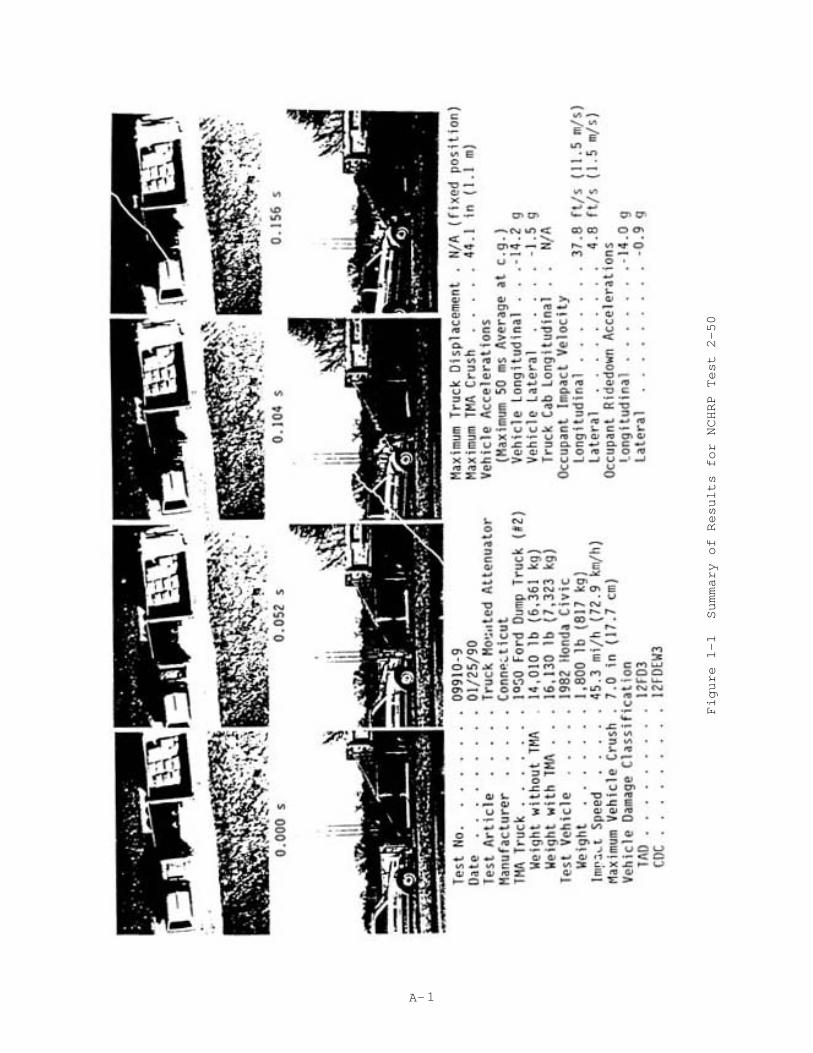
Figure 1-1 Summary of Results for NCHRP 350 Test 2-50 A—l
Figure 1—2 Vehicle/Support Geometrics Before Test 2—50 A—2
Figure 1—3 Deformed Cylinders After Test 2—50 A-3
Figure 1—4 Connecticut TMA After Test 2-50 A-4
Figure 1—5 Small Car After Test 2—50 A—5
Figure 2-1 Summary of Results for NCHRP 350 Test 2-51 A—6
Figure 2-2 Vehicle/Support Geometrics Before Test 2-51 A—7
Figure 2—3 Both Vehicle’s Trajectory After Test 2—51 A—8
Figure 2-4 Connecticut TMA After Test 2-51 A-9
Figure 2—5 Pickup After Test 2—51 A—10
Figure 3—1 Summary of Results for NCHRP 350 Test 2-52 A-l1
Figure 3-2 Vehicle/Support Geometrics Before Test 2-52 A-12
Figure 3—3 Both Vehicle’s Trajectory After Test 2—52 A—l3
Figure 3-4 Connecticut TMA After Test 2-52 A—l4
Figure 3—5 Pickup After Test 2—52 A—l5
Figure 4-1 Summary of Results for NCHRP 350 Test 3-53 A-l6
Figure 4-2 Vehicle/Support Geometrics Before Test 2—53 A—l7
Figure 4-3 Both Vehicle’s Trajectory After Test 2—53 A—l8
Figure 4-4 Connecticut TMA After Test 2—53 A-19
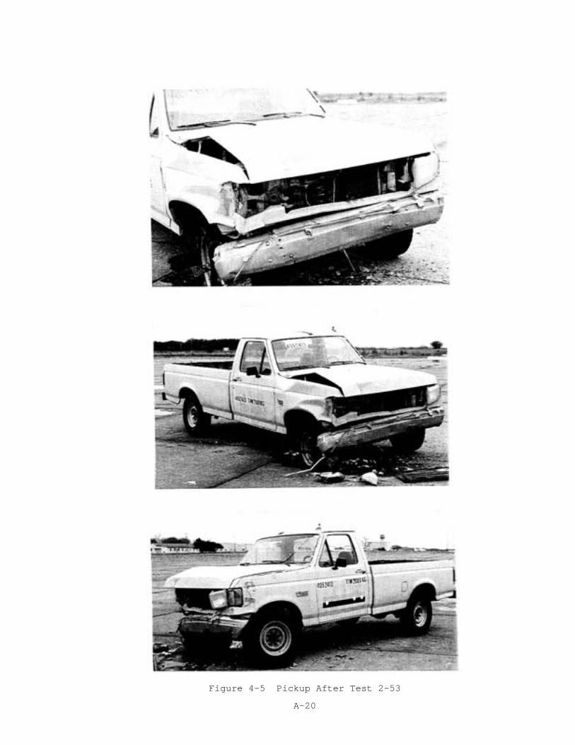
Figure 4—5 Pickup After Test 2—53 A—20

1
SUMMARY OF THE NCHRP REPORT 350 CRASH TEST
RESULTS FOR THE CONNECTICUT TRUCK MOUNTED ATTENUATOR
Background
In May 1975, the Connecticut Department of Transportation (C0nnDOT) initiated
a research effort to design, build and crash test a truck mounted attenuator (TMA)
constructed of steel tubular members /1,2,3/. The system was designed to protect
C0nnDOT maintenance and construction personnel performing field duties. The truck
mounted attenuator system has been in use for over 15 years, and approximately 60
units are currently being employed by C0nnDOT field personnel alone /3,4/. In fact,
the very favorable accident experience of the portable system provided the
incentive to apply the same engineering principles to the design and full scale
crash testing to other crash cushion designs.
The TMA research was precipitated by the safety concerns of C0nnDOT field
personnel. Increasingly, maintainers were exposed to errant motorists during the
course of normal workdays. Initial research was performed at the University of
Connecticut, and a feasibility study determined that thick-wall cylinders provided
an excellent medium for dissipating the energy of an impacting vehicle.
Theoretical Basis for TMA
Kinetic energy is dissipated in the Connecticut TMA by plastically deforming
four thin-walled steel cylinders which are loaded laterally when impacted. The
deformation process involves the formation of plastic zones in the cylinders. There
are typically four such zones which are created in each cylinder during the
collapse process. After accounting for the strain—rate sensitivity of the steel
cylinders, which results in an increased energy dissipation capacity under impact
loading conditions, the steel cylinder

2
diameters, lengths, and individual wall thicknesses were designed such that
controlled energy dissipation could be achieved under impact with both light weight
and heavy vehicles.
Description of the System
The Connecticut TMA is made up of the following three major components:
1. Service vehicle guidance frame;
2. Energy—absorbing cylinders; and,
3. Impacting plate assembly.
The impacting plate assembly is constructed of 6061-T6 aluminum, as is the
aluminum tubing in the impacting plate assembly which slides inside the steel
structural tubing in the service vehicle guidance frame during collapse of the
device.
Figure 1 shows (in schematic form) the design configuration of the TMA. It is
composed of four cylindrical members formed from straight (A-36) steel plate
sections. The cylinders are bolted together and attached to the rear of the
carrying vehicle. The two 5x5.82 channel sections are attached to the aluminum
impacting plate to provide guidance for the system while it is collapsing. Varying
views of the system are shown as Figure 2.
Previous Full-Scale Crash Testing Program
A program of full—scale crash tests were conducted (1975—78) at Calspan
Corporation and the Texas Transportation Institute to test the design and
effectiveness of the Connecticut TMA /3/. The excellent results obtained
demonstrated conclusively that:

3
Figure 1 Detail Drawing of Connecticut TMA
4
Figure 1 (continued) Detail Drawing of Connecticut TMA

5
Figure 2 Connecticut TMA
6
1. The TMA absorbs the impacting energy in such a way that the accelerations
to which the automobile and service vehicle are subjected are acceptably
safe for the occupants of both vehicles.
2. The unit is inexpensive to repair. All that is required is to insert new
cylinders into the system.
3. There is no tendency for the impacting automobile to nose—dive under or
catapult over the TMA. In the event of an eccentric hit, intrusion of the
impacting vehicle into adjacent traffic lanes is minimal.
4. The TMA is easily attached to and removed from the carrying vehicle. It is
compact and designed for use in curved and hilly roads.
Truck Mounted Attenuator Crash Testing Requirements of NCHRP Report 350
NCHRP Report 350, /5/ entitled “Recommended Procedures for the Safety
Performance Evaluation of Highway Features,” was published in 1993. It was the
first document of its kind to consider the crash testing of TMA’s. Two different
TMA Test Levels are presented. Test Level 2, the basic level, deals with 70 km/h
crash test conditions, while Test Level 3 prescribes impact speeds of 100 km/h.
With the exception of these two different impact speeds, both test levels are
associated with the same required crash test matrix. This consists of the four
impact conditions illustrated in Figure 3, where test number 50 involves a 820 kg
automobile and tests 51, 52 and 53 employ 2000 kg pickup trucks. Note from Figure 3
that tests 52 and 53 are optional tests, while tests 50 and 51 are required.
There are two sets of evaluation criteria set forth in NCHRP Report 350 for
truck mounted attenuators. One set applies to the impacting vehicle and its
occupants, and the other set applies to the support vehicle and its driver. For
both the impacting vehicle and its occupants and the support vehicle and its
driver, occupant risk and vehicle trajectory are major concerns. In addition,

7
Figure 3 Impact Conditions for a TMA
8
since the TMA is attached to the support vehicle, the structural adequacy and
performance of the TMA is of paramount interest.
Connecticut TMA NCHRP Report 350 Crash Test Program
The Connecticut TMA is a Test Level 2 device, and the NCHRP Report 350 Test
Level 2 TMA crash test matrix is presented in Table 1. All four crash tests, the
two required and the two optional tests, were conducted at the Texas Transportation
Institute (TTI). Each of the four tests satisfied all of the requirements of NCHRP
Report 350. The crash test results are summarized in Table 2, and representative
photos of the crash tests performed are contained in the Appendix to this report.
The complete crash test reports are available to the reader on request. However,
the highlights of the four individual tests performed are discussed below.
Test No. l-NCHRP Report 350 Test 2-50
This test involves a 820 kg automobile impacting the TMA head-on with no offset at
70 km/h. It is a difficult test to pass because of the added requirement that the
service vehicle not be allowed to move forward during the test. This is
accomplished by butting the front end of the service vehicle against a rigid
barrier. This test was conducted as part of a TTI project entitled “Comparative
Crash Test Conducted on Seven Different Makes and Models of Truck Mounted
Attenuators /6/. The crash test details are shown in Figures 1-1 through 1-5 in the
Appendix. Although the impact speed of 72.9 km/h resulted in a kinetic energy
overload of 8.5 percent all test requirements were met. The occupant impact
velocity was 11.50 m/s (the maximum allowable value is 12 m/s), and the ridedown
acceleration was 14.00 g’s (below the preferred value of 15 g’s).

9
Table 1. NCHRP Report 350 Test Level 2 TMA Test Matrix
NCHRP Report 350 Test Designation
Vehicle Impact Speed (km/h)
Impact Angle (deg.)
Impact Point
2-50 820C 70 0 Head-on, no offset
2-51 2000P 70 0 Head-on, no offset
2-52 2000P 70 0 Head-on, width/3 offset
2-53 2000P 70 15 Angled, width/4 offset
Table 2. Summary of Crash Test Results
NCHRP Report 350 Test Designation
2-50 2-51 2-52 2-53
Vehicle mass (kg)
817 2000 2000 2000
Impact speed (km/h)
72.9 70.9 70.3 69.6
Impact Angle (degrees)
0 0 0 10.3
Vehicle impact location
Nose Nose Veh. width/3 offset
Veh. width/4 offset
Occupant impact velocity (m/s) Longitudinal (12 max. allowable) Lateral (12 max. allowable)
11.50 1.50
8.38 0.71
8.63 1.47
8.81 1.46
Occupant ridedown acceleration (peak 10 ms avg g’s) Longitudinal (20 max. allowable) Lateral (20 max. allowable)
14.00 0.90
15.65 1.56
15.08 4.03
10.68 4.81
Assessment Passed all requirements
Passed all requirements
Passed all requirements
Passed all requirements

10
Test No. 2-NCHRP Report 350 Test 2-51
In test 2—51, a 2000 kg pick-up truck impacts the TMA head-on with zero offset.
This impact condition is the same as in test 3-50 except for the fact that the
service vehicle is allowed to move forward during this test. The pre-test
configuration and post-test details are presented in Figures 2—1 through 2—5 in the
Appendix. The impact velocity was 70.9 km/h and all the test requirements were
again satisfied. The occupant impact velocity was 8.38 m/s (below the preferred
value of 9 m/s), and the occupant ridedown deceleration was 15.65 g’s.
Test No. 3-NCHRP Report 350 Test 2-52
This optional crash test is similar to Test 2—51 in that a 2000 kg pickup truck
impacts the TMA head-on. However, in this test, the impacting vehicle is offset
with respect to the TMA a distance of 1/3 of its width. This impact condition is
shown in Figure 3—2, and the test results are illustrated in Figures 3—1, 3—3, 3-4,
and 3--5 in the Appendix. All test requirements were again met. The impact velocity
was 70.3 km/h, the occupant impact velocity was a low 8.63 m/s, and the ridedown
deceleration was 15.08 g’s.
Test No. 4 - NCHRP Report 350 Test 2-53
Optional test 2-53 is a demanding one which measures the TMA’s ability to arrest a
2000 kg pickup impacting the device at a 15 degree angle and a width/4 offset. The
geometrics for this impact are shown in Figure 4-2 and Figures 4-1, 4—3, 4—4, and
4-5 in the Appendix show the post—impact results. In this test, both the occupant
impact velocity value of 8.81 m/s and the occupant ridedown deceleration value of
10.68 g’s were below the respective preferred values of 9 m/s and 15 g’s. The
impact velocity in this test was 69.6 km/h.

11
Conclusion
In summary, four crash test were conducted, and all four tests passed all of
the requirements of NCHRP Report 350. Three of the four occupant impact velocities
were below the preferred value of 9 m/s, and all four occupant ridedown
decelerations were either under or just over the preferred value of 15 g’s. The
maximum allowable occupant ridedown deceleration in NCHRP Report 350 is 20 g’s.
Detailed crash test information on these four tests are available on request.
Complete design and construction details as well as video tapes of tests performed
on the system are also available to interested parties.
As a result of this successful test program, the Connecticut TMA has been
presented to the Federal Highway Administration for approval to be used on the U.S.
National Highway System.

12
REFERENCES
1. Carney, J. F., III, “Experimental Evaluation of a Portable Energy-absorbing System for Highway Service Vehicles - Final Report, For Phase I,” Report No. 402—1—77—3, January 1977.
2. Carney, J. F., III, “Experimental Evaluation of a Portable Energy-Absorbing System for Highway Service Vehicles - Final Report,” Report No. 402-F-79--l, December 1978. Abridgement published in TRB Record #679.
3. Carney, J. F., III, “Crash Testing of a Portable Energy—Absorbing System for Highway Service Vehicles,” TRB Record 833.
4. Carney, J. F., III, and Larsen, D. A., “Accident Experience with the Connecticut Crash Cushion,” Report No. 343—16—80-19, December 1980.
5. Ross, H. E., et al, “Recommended Procedures for the Safety Performance Evaluation of Highway Features,” NCHRP Report 350, 1993.
6. Campisi, Wanda L., “Comparative Crash Tests Conducted on Seven Different Makes and Models of Truck Mounted Attenuators (TMA’s),” Report No. TTI:2—4-89—991, August 1991.
7. Aiberson, Dean C., “Test and Evaluation of the Connecticut Truck Mounted Attenuator,” Report No. 405241—1, November.
8. Alberson, Dean C., “Test and Evaluation of the Connecticut Truck Mounted Attenuator,” Report No. 405241—2, November 1994.
9. Aiberson, Dean C., “Test and Evaluation of the Connecticut Truck Mounted Attenuator,” Report No. 405241—3, January 1995.

13
APPENDIX
Summary of Test Results and
Typical Photos of NCHRP 350 Tests Performed

14
NCHRP 350 Test 2-50
A- 1
Figure 1-1 Summary of Results for NCHRP Test 2-50

A- 2
Figure 1-2 Vehicle/Support Geometrics Before Test 2-50

A- 3
Figure 1-3 Deformed Cylinders After Test 2-50

A- 4
Figure 1-4 Connecticut TMA After Test 2-50

A- 5
Figure 1-5 Small Car After Test 2-50

NCHRP 350 Test 2-51

A-6
Figure 2-1 Summary of Results for NCHRP 350 Test 2-51

A-7
Figure 2-2 Vehicle/Support Geometrics Before Test 2-51

A-8
Figure 2-3 Both Vehicle’s Trajectory After Test 2-51

A-9
Figure 2-4 Connecticut TMA After Test 2-51

A-10
Figure 2-5 Pickup After Test 2-51

NCHRP 350 Test 2-52

A-11
Figure 3-1 Summary of Results for NCHRP 350 Test 2-52

A-12
Figure 3-2 Vehicle/Support Geometrics Before Test 2-52

A-13
Figure 3-3 Both Vehicle’s Trajectory After Test 2-52

A-14
Figure 3-4 Connecticut TMA After Test 2-52

A-15
Figure 3-5 Pickup After Test 2-52

NCHRP 350 Test 2-53

A-16
Figure 4-1 Summary of Results for NCHRP 350 Test 3-53

A-17
Figure 4-2 Vehicle/Support Geometrics Before Test 2-53

A-18
Figure 4-3 Both Vehicle’s Trajectory After Test 2-53

A-19
Figure 4-4 Connecticut TMA After Test 2-53
A-20
Figure 4-5 Pickup After Test 2-53


![SUMMARY CHANGES FOR NCHRP REPORT 350 GUIDELINES [NCHRP 22-14 (02)] Keith A. Cota, Chairman Technical Committee on Roadside Safety May 4, 2007](https://img.pdfslide.us/doc/110x75/56649cf75503460f949c6c3d/summary-changes-for-nchrp-report-350-guidelines-nchrp-22-14-02-keith-a.jpg)