Embed Size (px)
Citation preview
)0 /S
N A T I O N A L A E R O N A U T I C S A N D S P A C E A D M I N I S T R A T I O N
Technical Report 32-1075
Summary of the Functions and Capabilities
of the Structural Analysis and
Matrix Interpretive System
Computer Program
T. E. Lang
J E T P R O P U L S I O N L A B O R A T O R Y
C A L I F O R N I A I N S T I T U T E O F T E C H N O L O G Y
P A S A D E N A , C A L I F O R N I A
April 1, 1967
https://ntrs.nasa.gov/search.jsp?R=19670015743 2018-07-29T15:40:54+00:00Z
N A T I O N A L A E R O N A U T I C S A N D S P A C E A D M I N I S T R A T I O N
Technical Report 32-1075
Summary of the Functions and Capabilities
of the Structural Analysis and
Matrix Interpretive System
Computer Program
T. E. Lang
Approved by
c.M. E. Alper, Manager
Applied Mechanics Section
J E T P R O P U L S I O N L A B O R A T O R Y
C A L I F O R N I A I N S T I T U T E O F T E C H N O L O G Y
P A S A D E N A , C A L I F O R N I A
April 1, 1967
TECHNICAL REPORT 32-J 075
Copyright © 1967Jet Propulsion Laboratory
California Institute of Technology
Prepared Under Contract No NAS 7-100National Aeronautics & Space Administration
ll
Foreword
The Structuial AnaKsis and Mat r ix In t e ip i e l i xe S\stem (SAMIS) ComputerProgram described in this report was de\ eloped by Philco Coiporahon, WesternDevelopment Laboratories (WDL), Palo Alto, California, under contract to andin association with the Jet Propulsion Laboratory, Pasadena, California (JPLContract No. 950321). Development work by WDL was supervised b\ P. R Cobband R J Melosh as project engineer. The support effort by JPL uas underthe supervision of R R McDonald and M E Alper with T. E Lang as projectengineer Engineering and programming support at WDL \\as provided b\H. N. Christiansen, D. A. Diether and (Mrs ) M Brennan Conesponding suppoitat JPL was provided by L W Schmele, S. Utku. V. C Smith, and R. E Reed
Under a contract with NASA, the University of Georgia has established acenter for the dissemination of computer programs and computei information.This center, known as Computer Softuaie Management and Information Center(COSMIC), is working through the NASA Technology Uti l izat ion Office in con-junction with other NASA Centers and NASA Headquarters Thiough this jointeffort, computer programs and computer information developed b\ or for NASAwill be made available to any requester
Readers of this publication \ \ho desire furthei infoimat ion on obtaining theSAMIS Computer Program should dnect theii inquiries to COSMIC at theUniversity of Georgia Inquiries should be addressed as follows
COSMICCOMPUTER CENTERUnne i s i ty of GeoigiaAthens, Georgia 30601
JPL TECHNICAL REPORT 32-1075 iii

Page intentionally left blank
Page intentionally left blank
«v
Contents
I. Introduction . . 1
II. General Description of Program Characteristics ... . 2
III. Functions and Capabilities of the Program Generation Phase . 5
IV. Functions and Capabilities of the Program Manipulative Phase 7
A Multiplication Link (MULT) . 9
B Addition and Subtraction Link (ADDS, SUBS) . 10
C Transposition and Listing Links (FLIP, ROWS, COLS) 10
D Tn-Matrix Multiplication Link (WASH) 11
E Choleski Decomposition and Inversion Link (CHIN) . 11
F Simultaneous Equation Solution Links (CHOL, ITER) . 12
G Eigenvector and Eigenvalue Link (ROOT) 13
H Overall Program Performance in Solving Structural Problems 13
V. Review of Objectives in Program Development 15
A Techniques of Achieving a "Balanced" Program . 15
B Methods of Achieving Program Versatility . 18
C Methods of Insuring Program Reliability . . 19
VI. The Engineering Function in Structural Analyses with the
SAMIS Program . . . . 2 0
VII. SAMIS Links Under Development . 21
A. Second Order Differential Equation Links (LOCI, DEQS) 21
B Extended Choleski Decomposition Link (CHOL, Modified) . . . 22
C Buckling Load Prediction Links (BILD, SMAD) 22
D Root Extractor Link (POWR) . . .22
E Input Data Error Diagnostic Link (CHEX) 22
F Conical Element Generation Routines (CONE) 23
References . 23
JPL TECHNICAL REPORT 32-7075
Contents (contd)
Figures
1 Sample pseudo instruction 2
2 Core and tape assignments of the SAMIS program on IBM 7044/7094 computer 4
3 Gridpomt deflections and forces 5
4 Triangular grid array of a spherical shell sector 5
5 Generation phase functions and elements 6
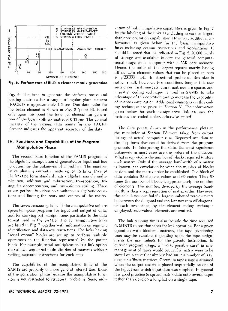
6 Performance of BILD in element-matrix generation 7
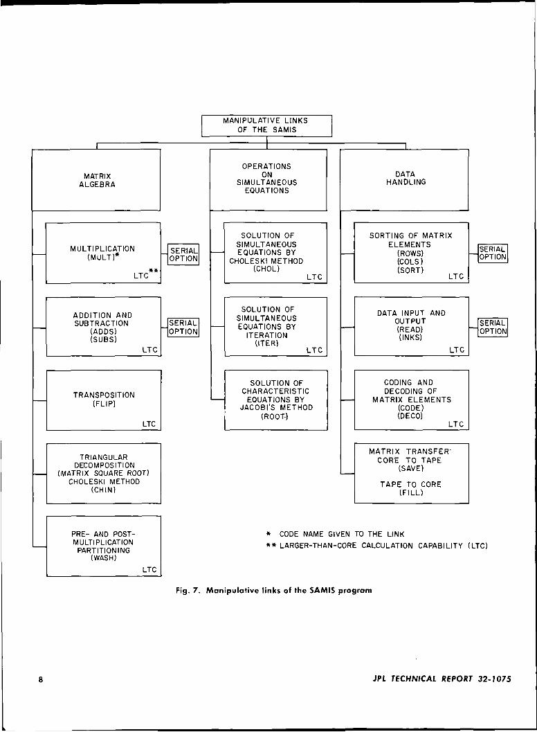
7 Manipulative links of the SAMIS program 8
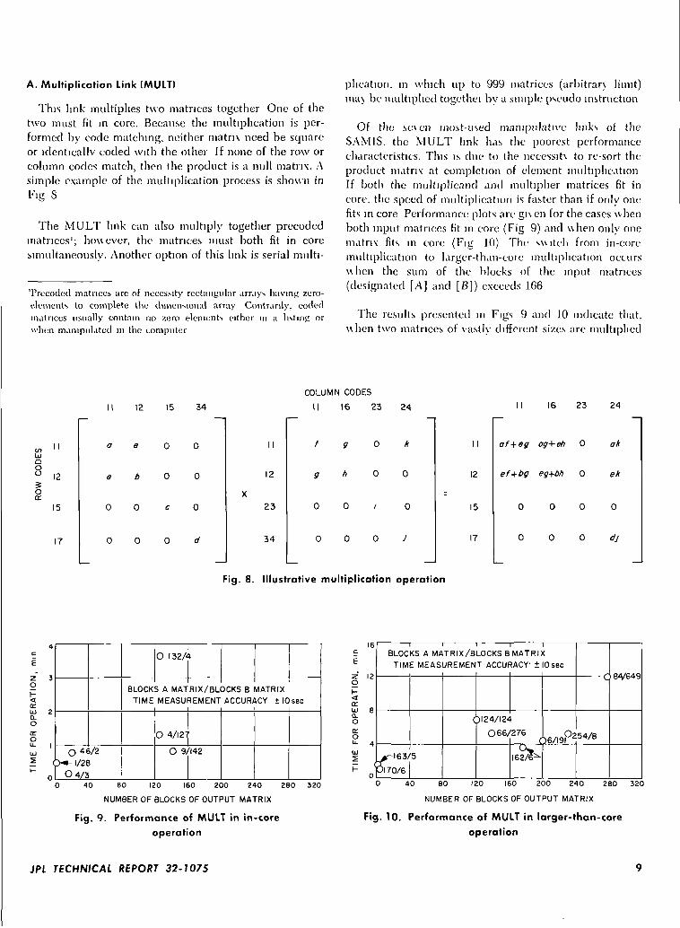
8 Il lustrative multiplication operation 9
9 Performance of MULT in in-core operation 9
10 Performance of MULT in larger-than-core operation 9
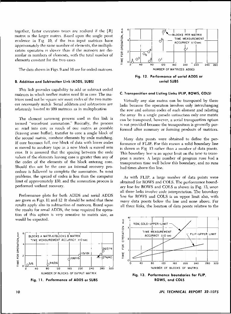
11 Performances of ADDS or SUBS 10
12 Performance of serial ADDS or serial SUBS 10
13 Performance boundaries for FLIP, ROWS, and COLS 10
14 Performance of the WASH link . 11
15 Performance of the CHIN link 11
16 Performance of CHOL link 12
17 Performance of ROOT link 13
18 Triangular grid array for quarter shallow shell 14
19 Pressure and thermal loading 14
20 Triangular array of 20-deg shell sector 15
21 Illustration of matrix coding technique 16
22 Matrix addition using coded elements 16
23 Structural idealization 18
24 Discretization of nonharmomc force 21
JPL TECHNICAL REPORT 32-1075
Abstract
The Junctions and capabilities of a large capacity Structural Analysis andMatrix Interpretive System (SAMIS) Digital Computer Program de\ eloped toanalyze frame and shell-type structures arc described. Included is a descriptionof each subprogram function with associated time-performance capabilitiesdefined, as established by program usage at a particular computer installationProgram development considerations given to modularization of the programfor functionally-diverse applications and reduction of errors m program usageare outlined. Finally two brief sections are included on program extensions cur-rently under development, and the participation of engmeciing personnel insolving structural problems with the SAMIS Computer Program.
JPL TECHNICAL REPORT 32-1075
Summary of the Functions and Capabilities of the StructuralAnalysis and Matrix Interpretive
System Computer Program
I. Introduction
This report descnbes the general characteristics andfunctions of the recently developed Structural Analysisand Matrix Interpretive System (SAM IS) computerprogram The program is designed to solve problemsinvolving matrix arithmetic, with particular emphasis onstructural applications The program can execute, eitherexclusively or sequentially, two basic operations. Frominput data that defines an idealization of a structure, theprogram generates structural matrices for any type ofelement available in the program element library Thisoperation is designated the generation phase The secondbasic operation is termed the manipulative phase, inwhich either generated or input matrices are manipulatedaccording to the rules of linear algebra In structuralproblems, the matrix manipulations mav be sequencedto compute displacements, stresses, reaction faces, ormode shapes and frequencies. The ability to computethese quantities for structural systems which are describedby a large number of simultaneous equations requiresgreater than in-core data access and storage capacityBecause of tins requirement, the program was developedas a chain s\stem as defined by specifications of the
FORTRAN II computer language operating under theIBSYS operating s\stem Based mainly upon the con-straint of computer running time, the SAMIS programoperates efficiently with matrices ranging from 100th to2,500th order
The generation phase of the program is based uponthe structural concepts of the finite element method, inparticular, the stiffness or displacement method To en-able the program to anaKzc a range of structural types(truss, plate, shell, composite shell-beam etc) , severalelements are programmed and cataloged in the programelement library Contained in the library are the generalline element suitable for representing axial, bending, andtorsion deformations, and the triangular plate elementwhich models membrane and bending deformations.
A checked-out version of the SAMIS program thatcontains a reasonable capability to solve structural prob-lems is described in this report This version of theSAMIS program is documented to aid users in gainingan understanding of its operation Technical aspects ofthe program, including definition of the algorithms used
JPL TECHNICAL REPORT 32-7075
in the manipulative subprograms, derivation of the ele-ment stiffness, stress, and loading matrices in the genera-tion link, and discussion of error control in programusage are discussed in Ref. 1. Programming aspects, L ^. „including definition of input-output format and content, data-handling functionsdescription of each chain link function, definition ofsubroutines within each link, and description of overallsystem logic and flow, are provided in Ref. 2 The setup and solution of typical shell and beam structuralproblems are reported in Ref 3
or links, the selection and sequencing of winch areuser-conti oiled and program-activated by a MasterIntelligence link, MINTS Modularity is basically bymatrix-manipulative, structural matrix-generation, and
Follow-on development of additional links for theSAMIS program, to be phased into the released versionof the program, is also outlined in this report Theselinks complement the released version of the programto provide greater capability in structural analysis It isplanned to release these additional checked-out linksand supplemental y documentation on (approximately) ayearly basis
The purpose of this report is to provide an overalldesciiption of the SAMIS program omitting detaileddescriptions of mathematical algorithms, computer oper-ations, and input-output formats It is not intended forreference in using the program For this purpose, theprogram user will find Refs 1—3 of value
In the following sections, the generation phase of theSAMIS is outlined, individual manipulative links aredescribed, major concepts in program development arediscussed, and the degree of participation bv technicalpersonnel in applying the program to engineering prob-lems is outlined
II. General Description of Program Characteristics
The SAMIS program is a segmented or chain systemwithin the guidelines of FORTRAN II computer lan-guage The program is composed of sixteen segments
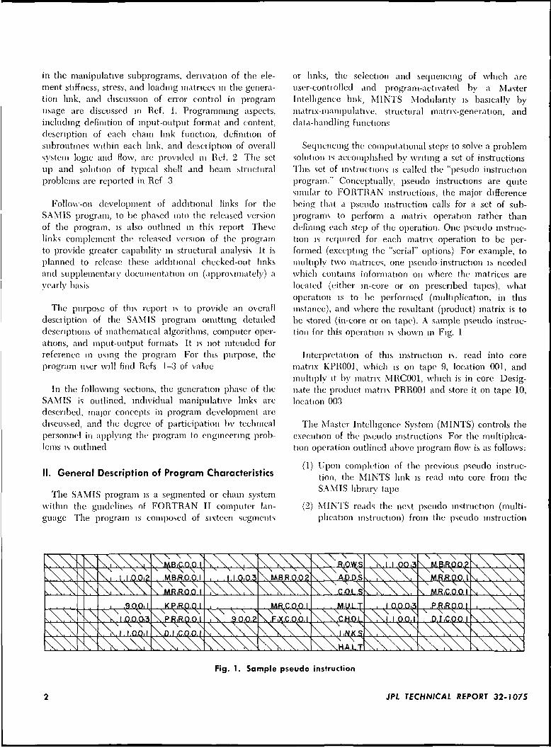
Sequencing the computational steps to solve a problemsolution is accomplished by writing a set of instructionsThis set of instructions is called the "pesudo instructionprogram." Conceptually, pseudo instructions are quitesimilar to FORTRAN instructions, the major differencebeing that a pseudo instruction calls for a set of sub-programs to perform a matrix operation rather thandefining each step of the operation. One pseudo instruc-tion is required for each matrix operation to be per-formed (excepting the "serial" options) For example, tomultiply two matrices, one pseudo-instruction is neededwhich contains information on where the matrices arelocated (either in-core or on prescribed tapes), whatoperation is to be performed (multiplication, in thisinstance), and where the resultant (product) matrix is tobe stored (in-core or on tape). A sample pseudo instruc-tion for this operation is shown in Fig. 1
Interpretation of this instruction is. read into corematrix KPR001, which is on tape 9, location 001, andmultiply it by matrix MRC001, which is in core Desig-nate the product matrix PRR001 and store it on tape 10,location 003
The Master Intelligence System (MINTS) controls theexecution of the pseudo instructions For the multiplica-tion operation outlined above program flow is as follows:
(!) Upon completion of the previous pseudo instruc-tion, the MINTS link is read into core from theSAMIS library tape
(2) MINTS reads the next pseudo instruction (multi-plication instruction) from the pseudo instruction
.R.OW.S\ \ \ x
10.
\, . 1.1.0.0,2 .M.BiR.0.0.1 i . .1.1.0,0.3 \ .MiB.R.0.0 2x \ x
N ,\ AD.D.S M.R.R.0.0.1\ \ \ \
\ MRiR.O,Q.I1 \.CiOL.S x. MRiC.O.O.I
.9.0.0,1 XPiR.O.O.I .M.R.C.O.O.I M.U.L T .I.O.O.O.3 .P.RiR.O.Q.IX x \ N
v. 1.0.0.0,3x X x \
X..P.RRQ.O.I\ \ x x N,\ . .9.0,0.2
^ x x x
\.FiX.CQ.Q.I\ x >.C.H.O.L .D.I.C.OO I
N \ \
v. l . l .0,0,1X X \ \vD.I iC.O.O.I
•> \ xI ,N.K S
\ x \ "•.HA.L.T
Fig. 1. Sample pseudo instruction
JPL TECHNICAL REPORT 32-? 075
program tape and determines which tapes areneeded and what funct ion is to he performed
(3) MINTS positions all of the tapes involved (tape 9at location 001. tape 10 at location 003), so thatthe next location on the tape is either the start ofthe input data for the operation or the designatedposition for the output data
(4) MINTS then locates on the SAMIS library tape theoperation link (MULT) and brings the link intocore
(5) Control is then shifted to the operation link(MULT), which calls for the input matrices(KPR001, MRC001), performs the calculation(multiplication), and locates the resultant matrix(PRR001) in core or on tape, as specified
(6) Control is then returned to the MINTS link, andthe process is repeated \ \ i th the next pseudoinstruction
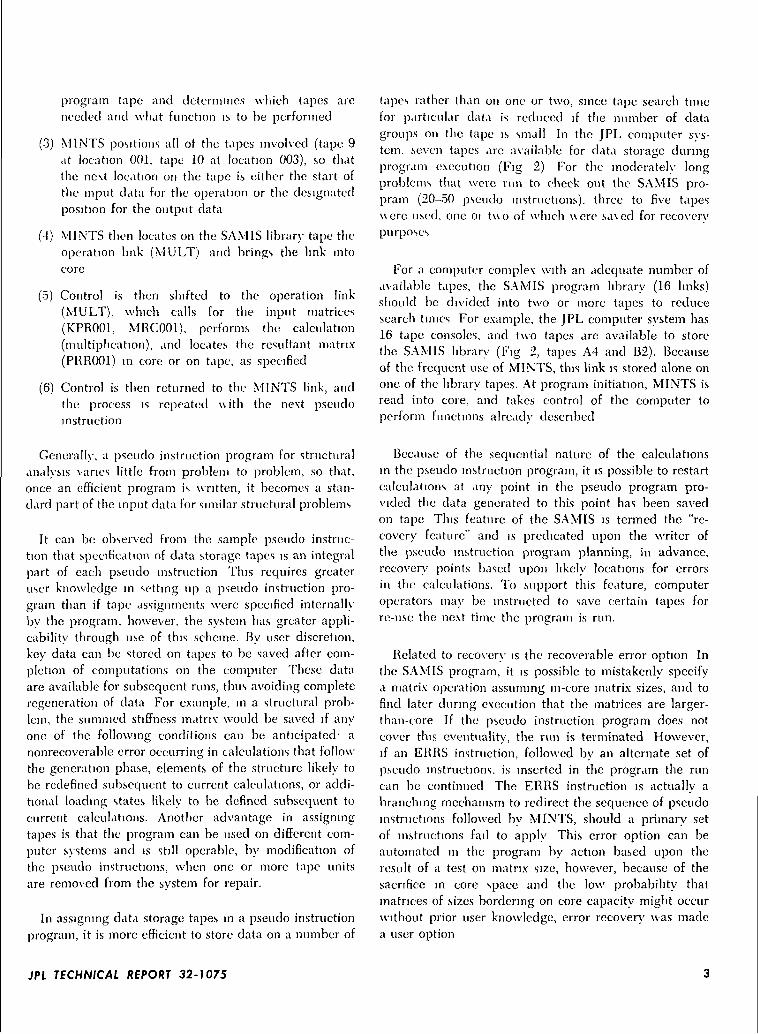
tapes rather than on one or two, since tape search timefor particular data is reduced if the number of datagroups on the tape is small In the JPL computer sys-tem, seven tapes are available for data storage duringprogram execution (Fig 2) For the moderately longproblems that were run to check out the SAMIS pro-pram (20-50 pseudo instructions), three to five tapes\\ere used, one 01 t \ \o of which \\ere sa\ed for recoverypurposes
For a computer complex with an adequate number ofavailable tapes, the SAMIS program library (16 links)should be divided into two or more tapes to reducesearch times For example, the JPL computer system has16 tape consoles, and two tapes are available to storethe SAMIS library (Fig 2, tapes A4 and 132). Becauseof the frequent use of MINTS, this link is stored alone onone of the library tapes. At program initiation, MINTS isread into core, and takes control of the computer toperform functions already described
Generally, a pseudo instruction program for structuralanalysis varies little from problem to problem, so that,once an efficient program is written, it becomes a stan-dard part of the input data for similar structural problems
It can be observed from the sample pseudo instruc-tion that specification of data storage tapes is an integralpart of each pseudo instruction This requires greateruser knowledge in setting up a pseudo instruction pro-gram than if tape assignments were specified internallyby the program, however, the system has greater appli-cability through use of this scheme. By user discretion,key data can be stored on tapes to be saved after com-pletion of computations on the computer These dataare available for subsequent runs, thus avoiding completeregeneration of data For example, in a structural prob-lem, the summed stiffness matrix would be saved if anyone of the following conditions can be anticipated- anonrecoverable error occurring in calculations that followthe generation phase, elements of the structure likely tobe redefined subsequent to current calculations, or addi-tional loading states likely to be defined subsequent tocurrent calculations. Another advantage in assigningtapes is that the program can be used on different com-puter systems and is still operable, by modification ofthe pseudo instructions, when one or more tape unitsare removed from the system for repair.
In assigning data storage tapes in a pseudo instructionprogram, it is more efficient to store data on a number of
Because of the sequential nature of the calculationsin the pseudo instruction program, it is possible to restartcalculations at any point in the pseudo program pro-vided the data generated to this point has been savedon tape This feature of the SAMIS is termed the "re-covery feature" and is predicated upon the writer ofthe pseudo instruction program planning, in advance,recover)' points based upon likely locations for errorsin the calculations. To support this feature, computeroperators may be instructed to save certain tapes forre-use the next time the program is run.
Related to recovery is the recoverable error option Inthe SAMIS program, it is possible to mistakenly specifya matrix operation assuming in-core matrix sizes, and tofind later during execution that the matrices are larger-than-core If the pseudo instruction program does notcover this eventuality, the run is terminated However,if an ERRS instruction, followed by an alternate set ofpseudo instructions, is inserted in the program the runcan be continued The ERRS instruction is actually abranching mechanism to redirect the sequence of pseudoinstructions followed by MINTS, should a primary setof instructions fail to apply This error option can beautomated in the program by action based upon theresult of a test on matrix size, however, because of thesacrifice in core space and the low probability thatmatrices of sizes bordering on core capacity might occurwithout prior user knowledge, error recovery was madea user option
JPL TECHNICAL REPORT 32-? 075
UJ
Z
tozUJ
ocoto
UJa.
COMPUTERSYSTEMSLIBRARY
CORE ASSIGNMENT
COMPUTER SYSTEMSIN USE
(2048 WORDS)
SAM IS SUBPROGRAMIN EXECUTION
(VARIABLE WORDS)
ERASEABLE DATAREGION-FOR
COMPUTATIONS(20,000 WORDS)
DATA COMMONTO ALL ROUTINES
(452 WORDS)
INTER-MEDIATE
DATASTORAGE
ALTERNATESAMISLIBRARY
SAMISPSEUDO
PROGRAM
PUNCHOUTPUT
AUXILIARYSTORAGE
AUXILIARYSTORAGE
AUXILIARYSTORAGE
INTER-MEDIATE
DATASTORAGE
LLJZZ
o
toI-zUJ
(ftCO
a.<
Fig. 2. Core and tape assignments of the SAMIS program on IBM 7044/7094 computer
JPL TECHNICAL REPORT 32-1075
To completely automate a structural analysis, the com-puter program must be set up to perform two basicfunctions, namely, geneiate the stiffness, stress, loading,and mass matrices, and then peiform the manipulationsnecessary to sol\e the problem Having summarized theoveiall progiam logic of the SAM IS progiam, we nowcan proceed to describe the generation and manipulativephases in some detail
III. Functions and Capabilities of the ProgramGeneration Phase
The first function, the generation of equation coeffi-cients, is performed by the computer when geometricand materials data are input to the program From theseinput data the SAM IS program will generate thefollowing
(1) Element stiffness and stress matrices
(2) Fixed-node forces due to temperature distributionand gradients
(3) Equivalent giidpomt forces due to un i form pres-sure loads
(4) Gravity loading vectors from imposed accelerations
(5) Element mass matrices for uniform!)-distributedmass \ \ i thm each element
This generation capability is represented in the SAMISprogram by one link, given the code name BILD. Amone or all of the element matrices listed above can begenerated in BILD for each type of element in theprogram element hbrarv
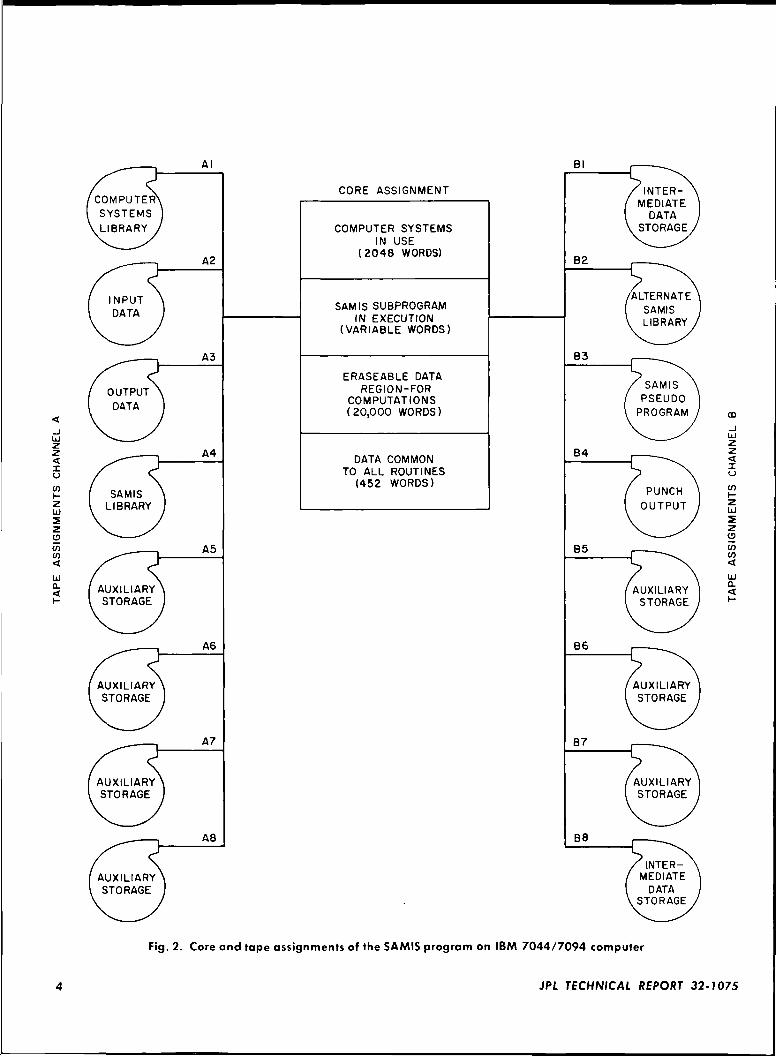
In the development of the SAMIS program, the in i t ia lobjective was to analyze regular, as well as irregular, thinplate and shell structures which may ha\e stiffening orsupport beam structural attachments Therefore, effort\\as devoted to the development of a flat, thin, triangularplate element of arbitrary mid-plane shape and uniformthickness If the triangular element adapted for the pro-gram is onented arbitrarily with respect to a set ofoverall coordinate axes, six variables describe the de-flection state at each apex (three orthogonal displace-ments and three orthogonal rotations) as shown inFig 3 Shown in Fig 3 are the generalized forces andmoments that correspond \ \ i th each displacement vari-able If a number of these triangles are set in an arrayin which the gridpomts lie on the neutral surface of ashell, the polyhedral system might appear as in Fig 4.
(a) DEFLECTIONS
M,
"* (b) FORCES
Fig. 3. Gridpoint deflections and forces
Z
^-TYPICAL GRIDPOINT
Fig. 4. Triangular grid array of a spherical shell sector
Clearly, for this idealization to be accurate each tri-angular element must represent membrane as well asbending states of deformation The numerical resultsreported in Ref 3 demonstrate this capability
The triangular plate element can represent a structureha \mg monotropic material properties (13 independentconstants in the constitutive equations), varying elasticmoduli \ \ i th temperature (interpolation and extrapolationof a material properties table), and varying thicknessand/or density properties A restriction on this elementrepresentation when the material is nomsotropic is thatthe principal material axes must align with prescribed
JPL TECHNICAL REPORT 32-1075
geometric axes unless a transformation of the constitutiveequations is made prior to introduction into the SAMISprogram
To represent stiffness of f iames and trusses the geneialline element is urmersally applicable This element repre-sents axial deformation, bending deformation in twoorthogonal planes, and torsional deformation It can havearbitrarily shaped cross-sections, provided the shear cen-ter and/or twist center are coincident with the principallongitudinal geometric axis This element representationoptionally includes the effects of shear deflection androtary inertia, and idealized types of end fixity can betreated
To extend the applicability of the triangular plate andline elements in structural idealizations, three supple-mental program features were incorporated in the BILDlink.
(1) Capability was provided to handle "substitute grid-points," i e, gridpomts that do not lie on theelastic axis or plane of the element, but connectto the element through weightless infinitely-rigidlinks The substitute gndpoint concept is applied inidealization of layered or offset stiffened structures
(2) Program changes were effected to represent the"gridpoint discontinuity condition," which is essen-tial when idealizing hinge or ball-socket joints instructures With structural joints of these types,certain displacements are discontinuous across thejoints, and the structural stiffness matrices must bemodified to represent these conditions
(3) The line element stiffness equations were redenvedand programmed to account for planar shearstresses acting on the edges This model is usefulin representing shear panel and spar elements inbuilt-up structural configurations.
These three supplemental element features, if inter-preted as separate element representations, increase theentries in the program element library significantly.
Several different mass matrices can be generated inBILD, depending upon user preference: Potential-energymass matrices (Ref 4), modified potential-energy massmatrices (Ref. 5), or finite-difference mass matrices (Ref. 6)can be generated for each type of element
For structural problems in which gridpoint boundaryconditions are not likely to be varied, the boundary
conditions can be specified in the element data. Thisfeature results in imposition of boundary conditionsprior to obtaining the total structural stiffness matrix.This capability was easily incorpoiated in the programbecause of the particular type of coding technique usedto identify each element of a matrix Further elabora-tion on this point is given in Section V
Equivalent gridpoint forces are computed internallyin the program for elements in the SAMIS library sub-jected to tempeiature gradients normal to the neutralaxes, temperature distributions, uniform accelerations,and/or pressure loads This system capability eliminateslengthy manual calculations to define gridpoint forces dueto these types of loads However, individual equivalentgridpoint forces may also be input, if the analyst de-sires to augment 01 replace the structural loading
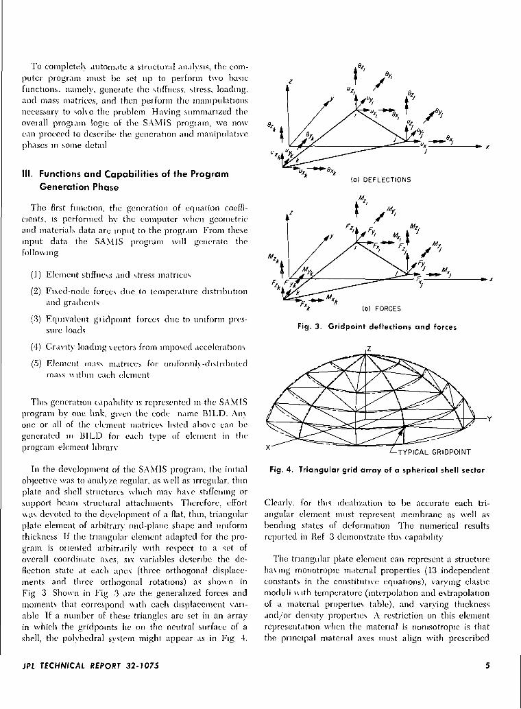
It is important to recognize that the types of struc-tures that can be analyzed are restricted only by thetypes of elements contained in the program library Pro-vision has been made for adding elements to this library\\ ithout serious revamping of the subroutines involved.For example, the input and output data formats aresufficiently general to accommodate a wide variety ofpossible element data The elements and functions ofthe generation link of the SAMIS are summarized inFig 5
Execution time of the BILD link has been assessedfor certain problems solved on the JPL computer Result-ing times as a function of the member of elements forwhich structural matrices were generated are plotted in
GENERATION LINK8ILD
LOAD VECTORSGENERATED
GRAVITY
- TEMPERATURE
- PRESSURE
MATRICESGENERATED
-
ELEMENTSTIFFNESS
ELEMENTSTRESS
ELEMENTMASS
Fig. 5. Generation phase functions and elements
JPL TECHNICAL REPORT 32-1075
2O1-<ccLJQ.OCEO c
KSoK
OKS
L OK
KSL
9KSL
TIM
B SK JL L
E MEAS
>TIFFNEJ>TIFFNESOADING
STRESS
UREMEN
5S MATFS MATFVECTOF
T ACCl
IX-BEAilX-FACEi-FACETFACET
JRACY
OB
d'T
tlOsec
40 80 120 160 200 240
NUMBER OF ELEMENTS
280 320
Fig. 6. Performance of BILD in element-matrix generation
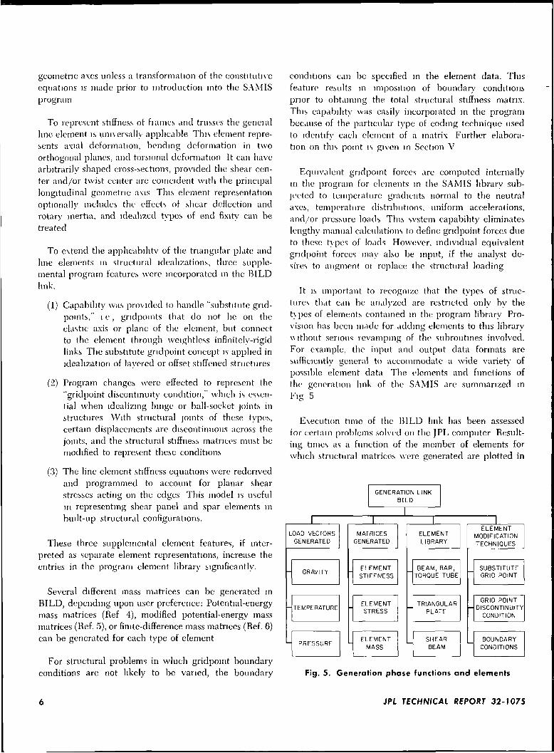
Fig. 6 The time to generate the stiffness, stress andloading matrices for a single triangular plate element(FACET) is approximately 1 6 sec One data point forthe beam element is shown in Fig. 6 (point B). Basedonly upon this point the time per element for genera-tion of the beam stiffness matnx is 033 sec The generallinearity of the various data points for the FACETelement indicates the apparent accuracy of the data
IV. Functions and Capabilities of the ProgramManipulation Phase
The second basic function of the SAMIS program isthe algebraic manipulation of generated or input matricesto determine the unknowns of a problem The manipu-lative phase is currently made up of 15 links Five ofthe links perform standard matrix algebra, namely multi-plication, addition and subtraction,, transposition, tri-angular decomposition, and row-column scaling. Threeothers perform functions on simultaneous algebraic equa-tions and finding the roots and vectors of the matrix
The seven remaining links of the manipulative set arespecial-purpose programs for input and output of data,and for carrying out manipulations particular to the dataformat used in the SAMIS. The 15 manipulative linksare listed in Fig 7 together with information on segmentidentification and data-size restrictions. The links having"serial option" blocks are set up to perform multipleoperations in the function represented by the parentblock. For example, serial multiplication is a link optionthat allows sequential multiplication of matrices withoutwriting separate instructions for each step
The capabilities of the manipulative links of theSAMIS are probably of more general interest than thoseof the generation phase because the manipulative func-tion is not restricted to structural problems Some indi-
cation of l ink manipulative capabilities is given in Fig. 7by the labeling of the links as including in-core or larger-than-core operation capabilities Howevei. additional in-formation is given below for the basic manipulativelinks including ccitam restrictions and applications Itshould be noted that, as indicated in Fig 2, 20.000 \\orclsof storage are available in-core for general computa-tional usage on a computer with a 32K core memoryHence, the Older of the largest square matrix havingall nonzero element values that can be placed in coreis \/20,000 = 141 In structural problems, this size israther small, ho\ve\er. two conditions temper this sizerestriction First, most structural matrices are sparse, anda matrix coding technique is used in SAMIS to takeadvantage of this condition and to increase the capabilityof in-core computation Additional comments on this cod-ing technique are given in Section V. The informationgiven below for each manipulative link assumes thematrices are coded unless otherwise stated
The data points shown in the performance plots inthe remainder of Section IV were taken from outputlistings of actual computer runs. Reported are data inthe onl) form that could be derived from the programprintouts In interpreting the data, the most significantunknowns in most cases are the orders of the matricesWhat is reported is the number of blocks required to storeeach matrix Only if the average bandwidth of a matrixis known, can correlation between the number of blocksof data and the matrix order be established. One block ofdata contains 60 element values and 60 codes Thus 60times the number of blocks is approximately the numberof elements This number, divided by the average band-width, is then a representation of matrix order. However,this calculation can fail if a large number of zero elementslie between the diagonal and the last nonzero off-diagonalof each row, since, by the element coding techniqueemployed, zero-valued elements are omitted.
The link running times also include the time requiredin MINTS to position tapes for link operation. For a givenoperation with identical matrices, the tape positioningtime may be variable, depending upon the tape assign-ments the user selects for the pseudo instruction. Incurrent program usage, a "worst possible ease" in mis-management of tapes would occur if a matrix were to bestored on a. tape that already had on it a number of, say,element stiffness matrices. Optimum tape usage is attainedwhen the output matrix is placed sequentially on one ofthe tapes from which input data was supplied In generalit is good practice to spread matrix data onto several tapesrather than develop a long list on a single tape.
JPL TECHNICAL REPORT 32-1075
MANIPULATIVE LINKSOF THE SAMIS
MATRIXALGEBRA
—MULTIPLICATION
(MULT)*
*ttLTC
ADDITION ANDSUBTRACTION
(ADDS)(SUBS)
LTC
TRANSPOSITION(FLIP)
LTC
TRIANGULARDECOMPOSITION
(MATRIX SQUARE ROOT)CHOLESKI METHOD
(CHIN)
PRE- AND POST-MULTIPLICATION
OPERATIONSON
SIMULTANEOUSEQUATIONS
SOLUTION OFSIMULTANEOUSEQUATIONS BY
CHOLESKI METHOD(CHOL)
LTC
SOLUTION OFSIMULTANEOUSEQUATIONS BY
ITERATIONUTER)
LTC
SOLUTION OFCHARACTERISTIC
EQUATIONS BYJACOBI'S METHOD
(ROOT-)
DATAHANDLING
SORTING OF MATRIXELEMENTS
(ROWS)(COLS)(SORT)
LTC
DATA INPUTOUTPUT(READ)(INKS)
AND
LTC
CODING ANDDECODING OF
MATRIX ELEMENTS(CODE)(DECO)
LTC
MATRIX TRANSFER-CORE TO TAPE
(SAVE)
TAPE TO CORE(FILL)
PARTITIONING(WASH)
LTC
* CODE NAME GIVEN TO THE LINK
** LARGER-THAN-CORE CALCULATION CAPABILITY (LTC)
Fig. 7. Manipulative links of the SAMIS program
JPL TECHNICAL REPORT 32-1075
A. Multiplication Link (MULT)
This l ink multiplies two matrices together One of thetwo must fit in core. Because the multiplication is per-formed by code matching, neither matrix need be squareor identically coded with the other If none of the row orcolumn codes match, then the product is a null matrix. Asimple example of the multiplication process is shown in
The MULT link can also multiply together precededmatrices'; houever, the matrices must both fit in coresimultaneously. Another option of this link is serial multi-
'Prccoclecl matrices arc of necessity rectangular arrays having zero-elements to complete the dimensional array Contranly, codedmatrices usually contain no zero elements either in a l ist ing orwhen manipulated in the computer
plication, in which up to 999 matrices (arbitrary, l imi t )ma\ be multiplied together by a simple pseudo instruction
Of the se\en most-used manipulative links of theSAMIS, the MULT link has the poorest performancecharacteristics. This is clue to the necessit\ to re-sort theproduct matrix at completion of element multiplicationIf both the multiplicand and multiplier matrices fit incore, the speed of multiplication is faster than if only onefits in core Performance plots are gu en for the cases whenboth input matrices fit in core (Fig 9) and \\hen only onematrix fits in core (Fig 10) The switch from in-coremultiplication to larger-than-eoie multiplication occursulien the sum of the blocks of the input matrices(designated [A] and [B]) exceeds 166
The results presented in Figs 9 and 10 indicate that,\ \hcn two matrices of vastly different sizes are multiplied
tnLUQ
8oOL
15
17
II 12 15 34
a e
e b 0
0 0 c 0
0 0
12
23
34
COLUMN CODES11 16 23 24
g h 0 0
0 0 0 J
12
15
17
I I 16 23 24
of+eg og+eh 0 ok
ef±bg eg+bh 0 ek
0 0 0 0
0 0 0 dj
Fig. 8. Illustrative multiplication operation
2O
CEUla.ox.ou_UJ•s.
O"6/2
>«-l/28
04/3
O !32/<\
BLOCKS A MATRIX/BLOCKS B MATRIXTIME MEASUREMENT ACCURACY ±IOsec
O 4/127
O 9/'142
40 80 120 160 200 240 280
NUMBER OF BLOCKS OF OUTPUT MATRIX
Fig. 9. Performance of MULT in in-coreoperation
zo
a.oa:o
16
12
8
4
o'
BLOCKS A MATRIX/BLOCKS B MATRIXTIME MEASUREMENT ACCURACY' ± 10 sec
*~I63/
OI70/6
5
(•JI24/I24
O 66/276C
162
WI9P254/8
84/649
0 40 80 120 160 200 240 280
NUMBER OF BLOCKS OF OUTPUT MATRIX
Fig. 10. Performance of MULT in larger-than-coreoperation
320
JPL TECHNICAL REPORT 32-1075
together, faster execution times are realized if the [B]matrix is the larger matrix. Based upon the single pointevidence in Fig 10, if the t\\ o input matrices haveapproximately the same number of elements, the multipli-cation operation is slouer than if the matrices are dis-similar in numbers of elements, with the total number ofelements constant for the t\vo cases
The data shown in Figs. 9 and 10 are for coded matrices.
B. Addition and Subtraction Link (ADDS, SUBS)
This link provides capability to add or subtract codedmatrices in which neither matrix need fit in core The ma-trices need not be square nor must codes of the two matri-ces necessarily match Serial addition and subtraction arearbitrarily limited to 999 matrices as in multiplication
The element summing process used in this link istermed "wavefront summation." Basically, the processis: read into core as much of one matrix as possible(leaving some buffer), transfer to core a single block ofthe second matrix, combine elements by code matching.If core becomes full, one block of data with lower codesis moved to auxiliary tape as a new block is moved intocoie. It is assumed that the spacing between the codevalues of the elements leaving core is greater than any ofthe codes of the elements of the block entering core.Should this not be the case an internal recovery pro-cedure is followed to complete the summation. In mostproblems, the spread of codes is less than the computerlimit of approximately 150, and the summation process isperformed without recovery.
Performance plots for both ADDS and serial ADDSare given in Figs. 11 and 12 It should be noted that theseresults apply also to subtraction of matrices. Based uponthe results for serial ADDS, the tune required for opera-tion of this option is very sensitive to matrix size, aswould be expected.
•z.o
UJQ.oIEo
BLOCKS A MATRIX/BLOCKS B MATRIX
TIME MEASUREMENT ACCURACY ±10 sec
Q5/6 -.84/26K
C
c,158/115
115/191 n£_
26/274
274/40
40 80 120 160 200 240 280 320
NUMBER OF BLOCKS OF OUTPUT MATRIX
Fig. 11. Performance of ADDS or SUBS
zg
a:UJa.oiro
± 0 A0 '
06
06°
o2
<]6
U
O1
!>6Y ^Bi
LOCKS PER MAI
TIME MEASUREACCURACY ±IC
A.
FRIX
MENT
sec
40 80 120 160 200 220
NUMBER OF MATRICES ADDED
240 260
Fig. 12. Performance of serial ADDS or
serial SUBS
C. Transposition and Listing Links (FLIP, ROWS, COLS)
Virtually any size matrix can be transposed by theselinks because the operation involves only interchangingthe row and column codes of each element and relistingthe array In a single pseudo instruction only one matrixcan be transposed, however, a serial transposition optionis not provided because the transposition is generally per-formed after summary or forming products of matrices.
Many data points were obtained to define the per-formance of FLIP. For this reason a solid boundary lineis shown in Fig 13 rather than a number of data points.This boundary line is an upper limit on the time to trans-pose a matrix A large number of program runs had atransposition time well below this boundary, and no runshad times above this line.
As with FLIP, a large number of data points wereobtained for ROWS and COLS. The performance bound-ary line for ROWS and COLS is shown in Fig. 13, sinceall three links involve code interpretation. The boundaryline for ROWS and COLS is an upper limit also, withmany data points below the line and none above. Forall three links, the location of data points relative to the
Oh-<
Q-O
cro
ROW, COLS-UPPER-LIMIT
TIME MEASUREMENTACCURACY ±10 sec -FLIP-UPPER LIMIT
80 120 160 200 240
NUMBER OF BLOCKS OF MATRIX
280 320
Fig. 13. Performance boundaries for FLIP,
ROWS, and COLS
10 JPL TECHNICAL REPORT 32-1075
boundary line was apparently matrix size-dependent,how ever, no consistent trends were observed
directly. Once the inverse of [0\[/] is found, the inverseof [M] is determined by multiplication, that is,
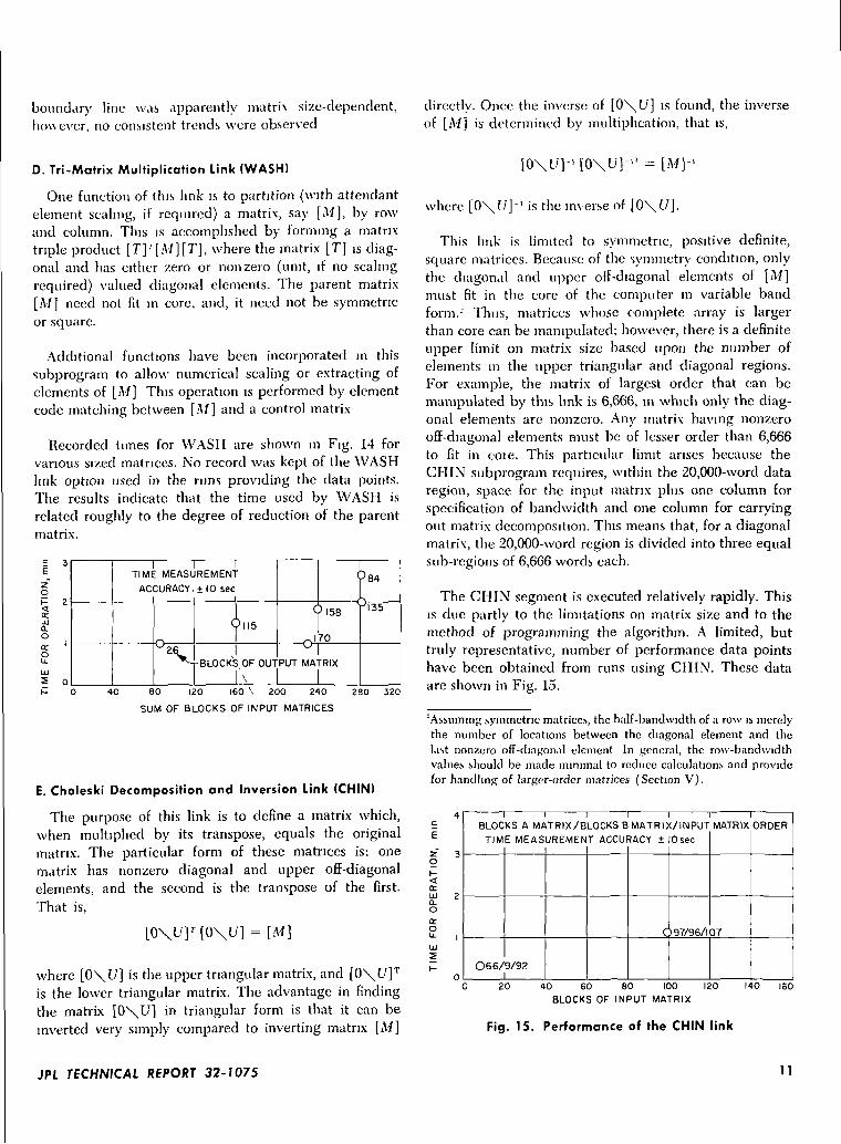
D. Tri-Matrix Multiplication Link (WASH)
One function of this link is to partition (with attendantelement scaling, if required) a matrix, say [M], by rowand column. This is accomplished by forming a matrixtriple product [T] '[M][T], where the matrix [T] is diag-onal and has either zero or nonzero (unit, if no scalingrequired) valued diagonal elements. The parent matrix[M] need not fit in core, and, it need not be symmetricor square.
Additional functions have been incorporated in thissubprogram to allow numerical scaling or extracting ofelements of [M] This operation is performed by elementcode matching between [M] and a control matrix
Recorded times for WASH are shown in Fig. 14 forvarious sized matrices. No record was kept of the WASHlink option used in the runs providing the data points.The results indicate that the time used by WASH isrelated roughly to the degree of reduction of the parentmatrix.
2O
ocLu0.O
(COu.LU
5
1TIME MEASL
ACCURACY.
2V
REMENT
± 10 seci
Qll5
J-BLOCKS OF OUT
\
|
Ql58 '
n!70
PUT MA •RIX
3 84
^r-
80 120 160 \ 200 240
SUM OF BLOCKS OF INPUT MATRICES280 320
E. Choleski Decomposition and Inversion Link (CHIN)
The purpose of this link is to define a matrix which,when multiplied by its transpose, equals the originalmatrix. The particular form of these matrices is: onematrix has nonzero diagonal and upper off-diagonalelements, and the second is the transpose of the first.That is,
[0\l/]T [0\17] = [M]
where [0\l/] is the upper triangular matrix, and [0\l/]T
is the lower triangular matrix. The advantage in findingthe matrix [0\U] in triangular form is that it can beinverted very simply compared to inverting matrix [M]
[0\C/]-'[0\l/]-'T=[M]-'
where [0\U]-' is the inverse of [0\t/].
This link is limited to symmetric, positive definite,square matrices. Because of the symmetry condition, onlythe diagonal and upper off-diagonal elements of [M]must fit in the core of the computer in variable bandform.-' Thus, matrices whose complete array is largerthan core can be manipulated; however, there is a definiteupper limit on matrix size based upon the number ofelements in the upper triangular and diagonal regions.For example, the matrix of largest order that can bemanipulated by this link is 6,666, in which only the diag-onal elements are nonzero. Any matrix having nonzerooff-diagonal elements must be of lesser order than 6,666to fit in coie. This particular limit arises because theCHIN subprogram requires, within the 20,000-word dataregion, space for the input matrix plus one column forspecification of bandwidth and one column for carryingout matrix decomposition. This means that, for a diagonalmatrix, the 20,000-word region is divided into three equalsub-regions of 6,666 words each.
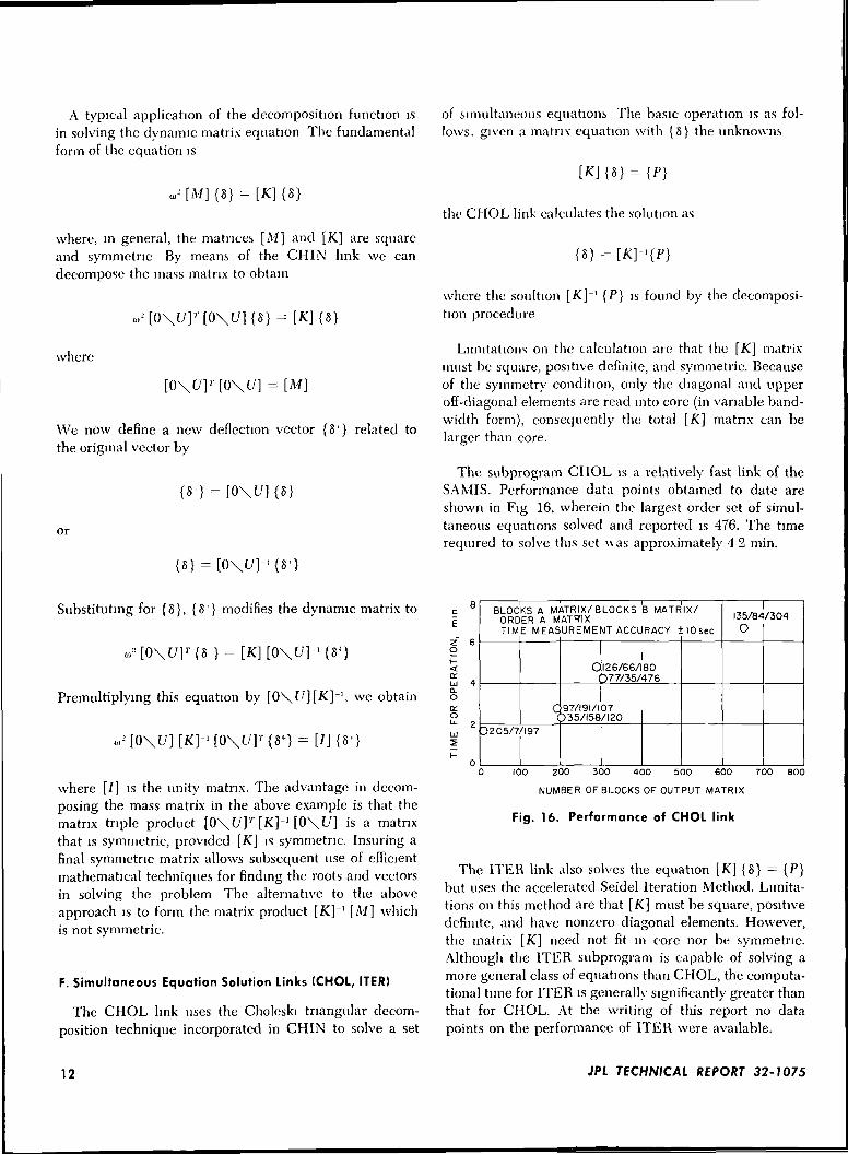
The CHIN segment is executed relatively rapidly. Thisis due partly to the limitations on matrix size and to themethod of programming the algorithm. A limited, buttruly representative, number of performance data pointshave been obtained from runs using CHIN. These dataare shown in Fig. 15.
^Assuming .symmetric matrices, the half-bandwidth of a row is merelythe number of locations between the diagonal element and theList nonzero off-diagonal element In general, the row-bandwidthvalues should be made minimal to reduce calculations and providefor handling of larger-order matrices (Section V).
E
z~o
trLUaoa:oLu
1BLOCKS A MATRIX/BLOCKS B MATRIX/INPUT
TIME MEASUREMENT ACCURACY ± 10 sec
O66/ 9/92
C 97/96/1
MATRIX
37
ORDER
20 40 60 80 100 120BLOCKS OF INPUT MATRIX
140 ISO
Fig. 15. Performance of the CHIN link
JPL TECHNICAL REPORT 32-1075 11
A typical application of the decomposition function isin solving the dynamic matrix equation The fundamentalform of the equation is
of simultaneous equations The basic operation is as fol-lows. given a matrix equation with {8} the unknowns
= [ K ] { S }
where, in general, the matrices [M] and [K] are squareand symmetric By means of the CHIN link we candecompose the mass matrix to obtain
where
[0\I7]r[0\f/] =
We now define a new deflection vector {81} related tothe original vector by
or
the CHOL link calculates the solution as
where the soultiontion procedure
{P} is found by the decomposi-
Limitations on the calculation are that the [K] matrixmust be square, positive definite, and symmetric. Becauseof the symmetry condition, only the diagonal and upperoff-diagonal elements are read into core (in variable band-width form), consequently the total [K] matrix can belarger than core.
The subprogram CHOL is a relatively fast link of theSAMIS. Performance data points obtained to date areshown in Fig 16, wherein the largest order set of simul-taneous equations solved and reported is 476. The timerequired to solve this set uas approximately 4 2 min.
Substituting for {8}, {8'} modifies the dynamic matrix to
Premultiplying this equation by [0\(7][K]~', we obtain
.r [0\ 17] [K]-'[0\l/r {«*} = [/] {8'}
where [/] is the unity matrix. The advantage in decom-posing the mass matrix in the above example is that thematrix triple product [0\C/]r [K]-1 [0\[7] is a matrixthat is symmetric, provided [K] is symmetric. Insuring afinal symmetric matrix allows subsequent use of efficientmathematical techniques for finding the roots and vectorsin solving the problem The alternative to the aboveapproach is to form the matrix product [K]~' [M] whichis not symmetric.
F. Simultaneous Equation Solution Links (CHOL, ITER)
The CHOL link uses the Choleski triangular decom-position technique incorporated in CHIN to solve a set
E
O
LdQ.O
ITO
BLOCKS A MATRIX/ BLOCKS B MATRIX/ORDER A MATRIXTIME MEASUREMENT ACCURACY ilOsec
3205/7
C7
'197
O(
97/191/1135/158
I26/66/S77/35/
07/I20
80476
135/8'O
/304
100 ZOO 300 400 500 600 700 800
NUMBER OF BLOCKS OF OUTPUT MATRIX
Fig. 16. Performance of CHOL link
The ITER link also solves the equation [K] {8} = {P}but uses the accelerated Seidel Iteration Method. Limita-tions on this method are that [K] must be square, positivedefinite, and have nonzero diagonal elements. However,the matrix [K] need not fit in core nor be symmetric.Although the ITER subprogram is capable of solving amore general class of equations than CHOL, the computa-tional time for ITER is generally significantly greater thanthat for CHOL. At the writing of this report no datapoints on the performance of ITER were available.
12 JPL TECHNICAL REPORT 32-1075
Basing the capacity of CHOL or 1TER on the size of[K] does not express the true limitation of the SAM ISsystem This can be demonstrated very easily. Assumethat the storage required for the diagonal and upper off-diagonal elements of [K] exceeds core A procedure calledpartitioning can be used effectively to allow use of theCHOL link in preference to ITER. The original matrixequation to be solved is
Assume this equation is partitioned into t\\o equal partsas follows:
K,,
This arrangement is actually an array of two matrix equa-tions, namely:
input of the matrix [R], where [R] is defined by
Solving the second equation for {Sj} yields
{8,} = [K2_.]-' {P_.} -[«•-•=]-' [K.-.1 {8,}
Substituting into the first equation gives
Referring back to the derivation of the dynamic equationoutlined in the CHIN description, it may be concludedthat
= [0\t/][K]- '[0\U]'
and
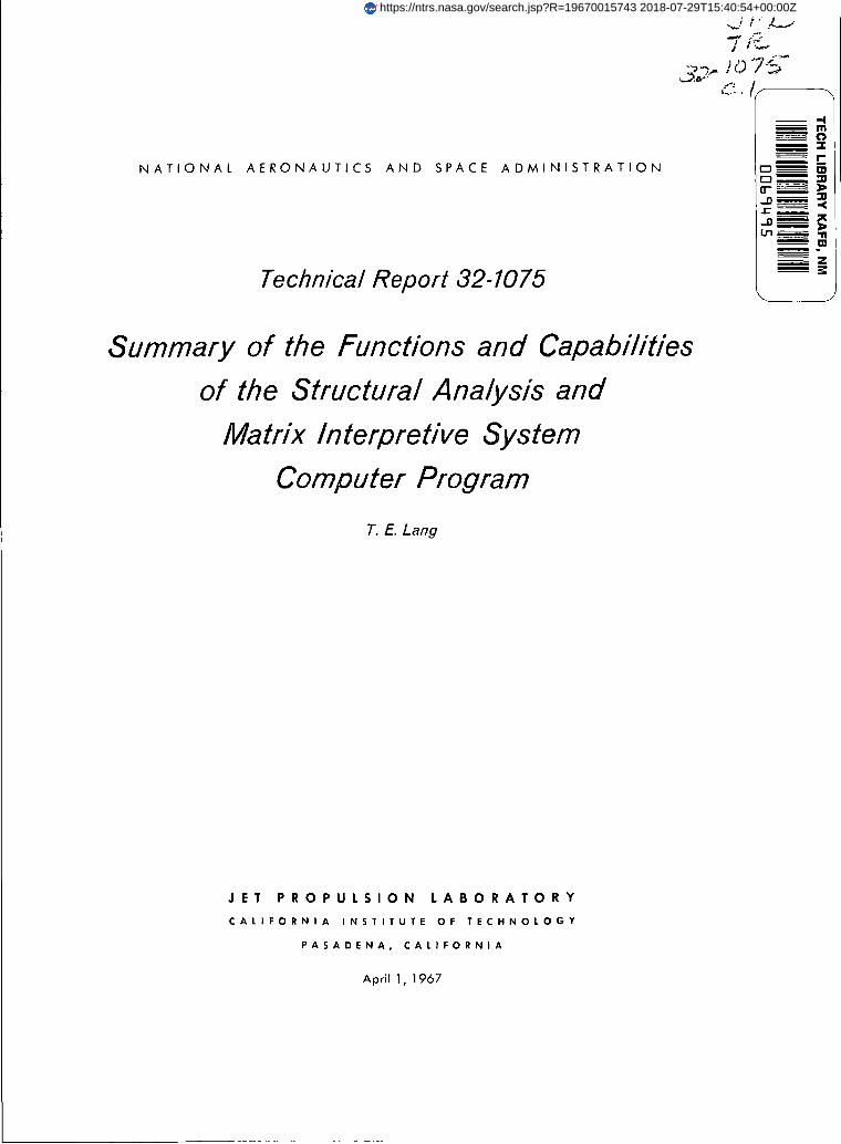
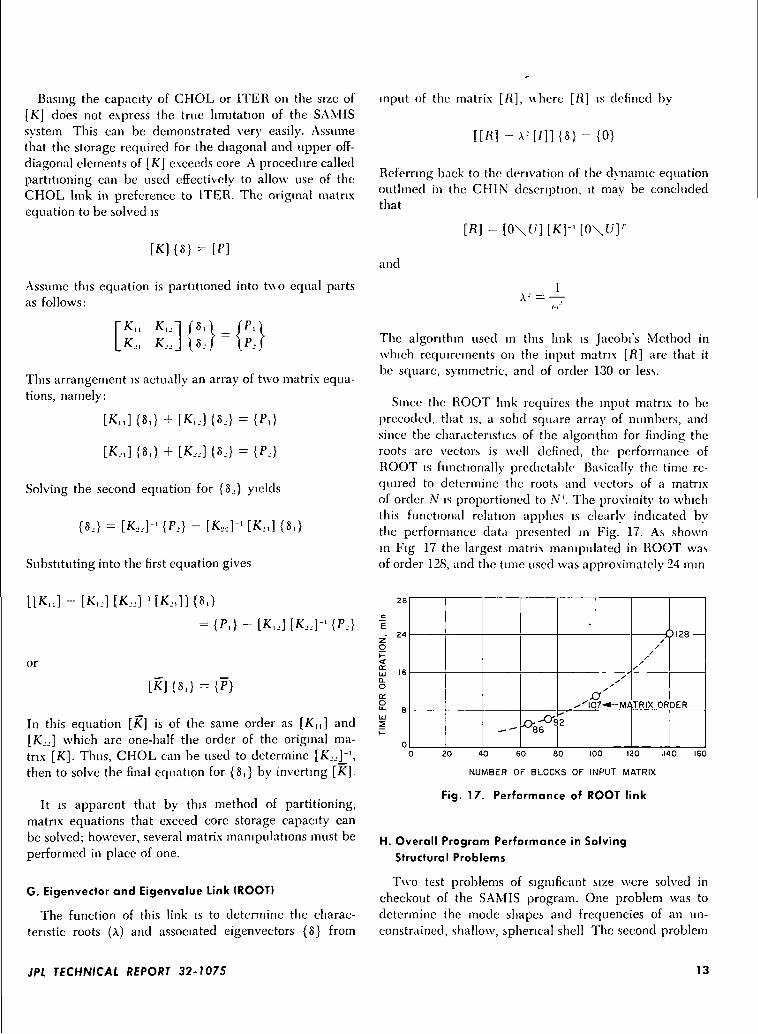
The algorithm used in this link is Jacobfs Method inwhich requirements on the input matrix [R] are that itbe square, symmetric, and of order 130 or less.
Since the ROOT link requires the input matrix to bepreceded, that is, a solid square array of numbers, andsince the characteristics of the algorithm for finding theroots are vectors is well defined, the performance ofROOT is functionally predictable Basically the time re-quired to determine the roots and vectors of a matrixof order N is proportioned to A". The proximity to whichthis functional relation applies is clearly indicated bythe performance data presented in Fig. 17. As shownin Fig 17 the largest matrix manipulated in ROOT wasof order 128, and the time used was approximately 24 mm
= {P, } - [K 1 J ] [K J J ] - {P J }
or
In this equation [K] is of the same order as [K,,] and[K.,j] which are one-half the order of the original ma-trix [K]. Thus, CHOL can be used to determine [K,,Y\then to solve the final equation for {S,} by inverting [K].
It is apparent that by this method of partitioning,matrix equations that exceed core storage capacity canbe solved; however, several matrix manipulations must beperformed in place of one.
G. Eigenvector and Eigenvalue Link (ROOT)
The function of this link is to determine the charac-teristic roots (A) and associated eigenvectors {8} from
28
c
E
z 24
O
5 16Q.O(X
e eUJ5K
0
-- °-8fs
•
ss
-'"'I0.7-*- M/!
H
/
s
TRIX OR DER
20 40 60 80 100 120 .140 160
NUMBER OF BLOCKS OF INPUT MATRIX
Fig. 17. Performance of ROOT link
H. Overall Program Performance in SolvingStructural Problems
Two test problems of significant size were solved incheckout of the SAMIS program. One problem was todetermine the mode shapes and frequencies of an un-constrained, shallow, spherical shell The second problem
JPL TECHNICAL REPORT 32-1075 13
was the determination of the deflections and stresses ofthe same shallow shell, with its outer edge clamped andthe shell being subjected to a uniform pressure loadingand a temperature induced loading. Complete resultsof these problems are reported in Ref. 3.
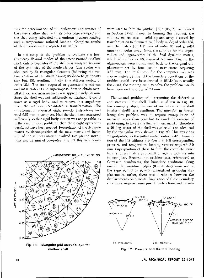
In the setup of the problem to evaluate the low-frequency fle.xural modes of the unconstrained shallowshell, only one-quarter of the shell was analyzed becauseof the symmetry of the mode shapes This sector wasidealized by 54 triangular elements (following the sur-face contour of the shell) having 38 discrete gndpomts(see Fig. 18), resulting initially in a stiffness matrix oforder 324. The time required to generate the stiffnessand mass matrices and superimpose them to obtain over-all stiffness and mass matrices was approximately 3 5 min.Since the shell was not sufficiently constrained, it couldmove as a rigid body, and to remove this singularityfrom the matrices necessitated a transformation Thetransformation required eight pseudo instructions andused 6.67 mm to complete. Had the shell been restrainedsufficiently so that rigid body motion was not possible, asis the case in most problems, then these eight operationswould not have been needed Formulation of the dynamicmatrix by decomposition of the mass matrix and inver-sion of the stiffness matrix involved five pseudo instru-tions and 12 mm of computer time. Of this time 5 min
GRIDPOINT NO./-ELEMENT NO.
were used to form the product [K]~ l[0\(7] r as definedin Section IV-E, above. In forming this product, thestiffness matrix was a solid square array (caused bytransformation to eliminate rigid body mode) of order 185,and the matrix [0\C/]7 was of order 86 and a solidupper triangular array Next, the solution for the eigen-values and eigenvectors of the final dynamic matrix,which was of order 86. required 55 min. Finally, theeigenvectors were transformed back to the original dis-placement set by four pseudo instructions requiring3 67 min. The total tune for the computer run wasapproximately 33 min If the boundary conditions of theproblem could have been treated in BILD (as is usuallythe case), the running time to solve the problem wouldhave been on the order of 22 mm
The second problem of determining the deflectionsand stresses in the shell, loaded as shown in Fig 19,has symmetry about the axis of revolution of the shell(uniform shell) as a condition. The intention in formu-lating this problem was to require manipulation ofmatrices larger than core but to avoid the exercise ofpartitioning to invert the final stiffness matrix Thereforea 20 deg sector of the shell was selected and idealizedby the triangular array shown in Fig 20 This array has70 gndpoints, so the initial matrix order is 420. Genera-tion of the 108 stiffness matrices and 108 correspondingpressure and temperature loading vectors required 3 0mm Superposition of these to form the complete struc-tural stiffness matrix and loading vectors took 4 2 minto complete. Because the problem was referenced toCartesian coordinates, the boundary conditions alongone of the meridmal edges (0 ~ 20 deg) were not ofthe type u, =0 or nt ^ 0 (generalized gndpoint dis-placement), rather, there was a relation between thedisplacement components Imposition of these boundaryconditions required nine pse-udo instructions and 14 min
0 075 in0075m
AMBIENT BEFOREHEATING 70° F
1086
Fig. 18. Triangular grid array for quartershallow shell
(a )PRESSURE (b) THERMAL
Fig. 19. Pressure and thermal loading
14 JPL TECHNICAL REPORT 32-1075
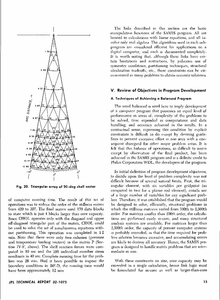
Fig. 20. Triangular array of 20-deg shell sector
of computer running time. The result of this set ofoperations was to reduce the order of the stiffness matrixfrom 420 to 307. The final matrix used 170 data blocksto store which is just 4 blocks larger than core capacity.Since CHOL operates only with the diagonal and upperoff-diagonal triangular part of the matrix, CHOL couldbe used to solve the set of simultaneous equations with-out partitioning. This operation was completed in 12min. Note that there were only two columns (pressureand temperature loading vectors) in the matrix P (Sec-tion IV-F, above). The shell reaction forces were com-puted in 10 sec and the 108 individual member stressresultants in 40 sec. Complete running time for the prob-lem was 26 min. Had it been possible to impose theboundary conditions in BILD, the running time wouldhave been approximately 12 min
The links described in this section are the basic-manipulative functions of the SAMIS piogram. All arelimited to calculations with linear equations, and all in-volve only real algebra The algorithms used in each sub-program are considered efficient for applications on adigital computer, and each is documented completely.It is worth noting that, although these links have cer-tain limitations and restrictions, by judicious use ofsymmetry conditions, partitioning techniques, structuralidealization tradeoffs, etc., these constraints can be cir-cumvented in many problems to obtain accurate solutions.
V. Review of Objectives in Program Development
A. Techniques of Achieving a Balanced Program
The word balanced is used here to imply developmentof a computer program that possesses an equal level ofperformance in areas of. complexity of the problems tobe solved, time expended in computations and datahandling, and accuracy achieved in the results. In acontractual sense, expressing this condition by explicitconstraints is difficult to do except by devising guide-lines to prevent excessive effort in one area with a con-sequent disregard for other major problem areas. It isfelt that this balance of operations, so difficult to assessexcept by observation of the final product, has beenachieved in the SAMIS program and is a definite credit toPhilco Corporation VVDL, the developers of the program.
In initial definition of program development objectives,to decide upon the level of problem complexity was notdifficult because of several natural limits. First, the tri-angular element, with six variables per gridpoint (ascompared to two for a planar rod element), entails useof a large number of variables for any significant prob-lem Therefore, it was established that the program wouldbe designed to solve, efficiently, structural problems inwhich the stiffness matrices varied from 100th to 2,500thorder For matrices smaller than 100th order, the calcula-tions are performed easily in-core, and many structuralanalysis systems are available. For matrices larger than2,500th order, the capacity of present computer systems-is probably exceeded, in that the time required for prob-lem solution becomes excessive, and accumulating errorsare likely to destroy all accuracy Hence, the SAMIS pro-gram is designed to handle matrix problems that are inter-mediate in size.
With these constraints on size, core capacity may beexceeded in a single calculation, hence link logic mustbe formulated for in-core as well as larger-than-core
JPL TECHNICAL REPORT 32-1075 15
calculations When core is filled, the only way to accountfor remaining data is to use auxiliary storage It is wellknown that, \vhen auxiliary magnetic tape storage iscoupled with in-core calculations, the computational timeincreases significantly because of tape search and readtimes However, when the development began, there wasno alternative to this storage option and the time foroperations were minimized within this constraint.
In the SAMIS program, time minimizing is achievedby performing tape search and rewinding operations onas much of a non-interference basis as possible, consistentwith computer operation Every advantage has beentaken of existing computer capabilities to minimize tapesequencing, however, this still remains a major contri-bution to total computational time Within the limitationsof the existing JPL computer system, the tape problemcould be alleviated by writing an independent computermonitor system, specifically adapted to the SAMIS pro-gram However, this approach is not compatible withjob-sequencing practices at most computing centers.
Fortunately the developers of computer hardwarerecognize that this tape-core flow problem is a majoilimitation on computer performance Consequently, theyhave introduced several new components and a newmonitor system to increase storage capacity and decreasedata access time Disk filing reduces data access timeand increases storage capacity, and the FORTRAN IVmonitor system allows for tape reading and writing whilecalculations are performed in-core (buffering) These im-provements are not yet used in the SAMIS program butwhen they are incorporated, operation and computationtimes will be reduced significantly. In planning for theeventual conversion of the SAMIS to new monitor sys-tems, the developers have used the FORTRAN language(rather than machine language) in approximately 98% ofthe SAMIS program This strong emphasis on FORTRANis justified not only by the increased simplicity of adapt-ing the program to different monitor systems, but alsoby the ease of interpretation of subprogram functions bya user not completely familiar with the program
In addition to flow problems from link to link, andbetween core and tape, consideration was given to min-imization of the quantity of data required. Stiffnessmatrices, coordinate transformation matrices, and massmatrices are by nature sparse matrices, having consider-ably more zero-valued off-diagonal elements than nonzerovalues. Therefore, it is efficient both in core utilizationand in input data preparation to ignore the zero-valuedelements. Ignoring zero-valued elements cannot be easily
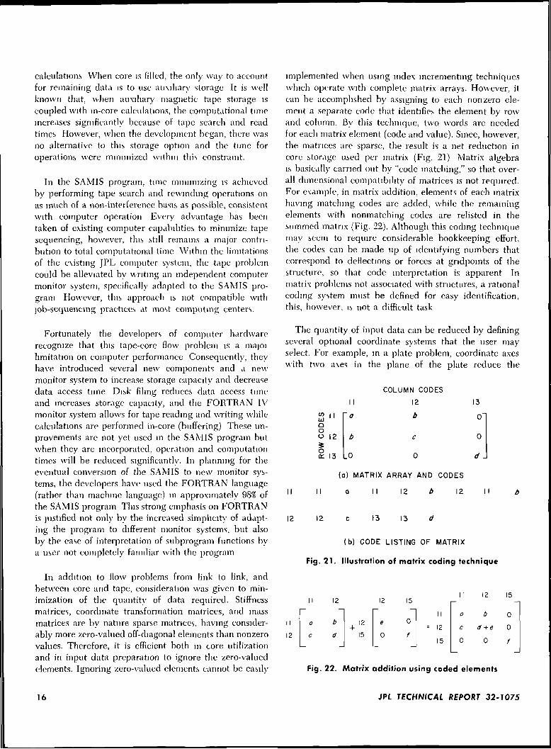
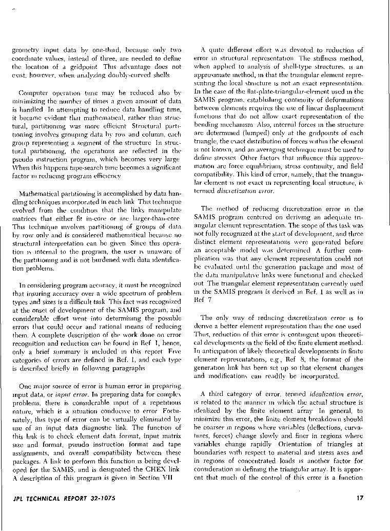
implemented when using index incrementing techniqueswhich operate with complete matrix arrays. However, itcan be accomplished by assigning to each nonzero ele-ment a separate code that identifies the element by rowand column. By this technique, two words are neededfor each matrix element (code and value). Since, however,the matrices are sparse, the result is a net reduction incore storage used per matrix (Fig. 21) Matrix algebrais basically carried out by "code matching," so that over-all dimensional compatibility of matrices is not required.For example, in matrix addition, elements of each matrixhaving matching codes are added, while the remainingelements with nonmatching codes are relisted in thesummed matrix (Fig. 22). Although this coding techniquemay seem to require considerable bookkeeping effort,the codes can be made up of identifying numbers thatcorrespond to deflections or forces at gndpomts of thestructure, so that code interpretation is apparent Inmatrix problems not associated with structures, a rationalcoding system must be defined for easy identification,this, however, is not a difficult task
The quantity of input data can be reduced by definingseveral optional coordinate systems that the user mayselect. For example, in a plate problem, coordinate axeswith two axes in the plane of the plate reduce the
aoo 12
1 1
'a
b
0
COLUMN CODES
12
b
c
0
13
0"
0
d J
(a) MATRIX ARRAY AND CODES
II a II 12 b 12
12 12 13 13
(b) CODE LISTING OF MATRIX
Fig. 21. Illustration of matrix coding technique
12
I I
12
12
1 1\2 15
~~|e 0
0 f
II
= 12
15
-
o
c
0
12
b
d + e
0
15
0
0
f
Fig. 22. Matrix addition using coded elements
16 JPL TECHNICAL REPORT 32-1075
geometry input data by one-thud, because only twocoordinate values, instead of three, are needed to definethe location of a gridpoint This advantage does notexist, however, when analyzing doubly-curved shells
Computer operation tune may be reduced also byminimizing the number of times a given amount of datais handled In attempting to reduce data handling time,it became evident that mathematical, rather than struc-tural, partitioning was more efficient Structural parti-tioning involves grouping data by rou and column, eachgroup representing a segment of the structure In struc-tural partitioning, the operations are reflected in thepseudo instruction program, which becomes very largeWhen this happens tape-search time becomes a significantfactor in reducing program efficiency
Mathematical partitioning is accomplished by data han-dling techniques incorporated in each link This techniqueevolved from the condition that the links manipulatematrices that either fit in-core or are larger-than-coreThis technique involves partitioning of groups of databy row only and is considered mathematical because nostructural interpretation can be given Since this opera-tion is internal to the program, the user is unaware ofthe partitioning and is not burdened with data identifica-tion problems.
In considering program accuracy, it must be recognizedthat insuring accuracy over a wide spectrum of problemtypes and sizes is a difficult task This fact was recognizedat the onset of development of the SAMIS program, andconsiderable effort went into determining the possibleerrors that could occur and rational means of reducingthem. A complete description of the work done on errorrecognition and reduction can be found in Ref 1, hence,only a brief summary is included in this report Fivecategories of errors are defined in Ref. 1, and each typeis described briefly in following paragraphs
One major source of error is human error in preparinginput data, or input error. In preparing data for complexproblems, there is considerable input of a repetitiousnature, which is a situation conducive to error Fortu-nately, this type of error can be virtually eliminated byuse of an input data diagnostic link. The function ofthis link is to check element data format, input matrixsize and format, pseudo instruction format and tapeassignments, and overall compatibility between thesepackages. A link to perform this function is being devel-oped for the SAMIS, and is designated the CHEX linkA description of this program is given in Section VII
A quite different effort \\as devoted to reduction oferror in structural representation The stiffness method,when applied to analysis of shell-type structures, is anapproximate method, in that the triangular element repre-senting the local structure is not an exact representation.In the case of the flat-plate-triangular-element used in theSAMIS program, establishing continuity of deformationsbetween elements requires the use of linear displacementfunctions that do not allow exact representation of thebending mechanism Also, internal forces in the structureare determined (lumped) only at the gndpomts of eachtriangle, the exact distribution of forces within the elementis not known, and an averaging technique must be used todefine stresses Other factors that influence this approxi-mation are force equilibrium, stress continuity, and fieldcompatibility. This kind of error, namely, that the triangu-lar element is not exact in representing local structure, istermed disci etization eiror.
The method of reducing discretization error in theSAMIS program centered on deriving an adequate tri-angular element representation. The scope of this task wasnot fu l l y recognized at the start of development, and threedistinct element representations were generated beforean acceptable model was determined A further com-plication was that any element representation could notbe evaluated unti l the generation package and most ofthe data manipulative links were functional and checkedout The triangular element representation currently usedin the SAMIS program is derived in Ref. 1 as well as inRef 7
The only way of reducing discretization error is toderive a better element representation than the one usedThus, reduction of this error is contingent upon theoreti-cal developments in the field of the finite element method.In anticipation of likely theoretical developments in finiteelement representations, e.g, Ref 8, the format of thegeneration link has been set up so that element changesand modifications can readily be incorporated.
A third category of error, termed idealization error,is related to the manner in which the actual structure isidealized by the finite element array In general, tominimize this error, the finite element breakdown shouldbe coarser in regions where variables (deflections, curva-tures, forces) change slowly and finer in regions wherevariables change rapidly Orientation of triangles atboundaries with respect to material and stress axes andin regions of concentrated loads is another factor forconsideration in defining the triangular array. It is appar-ent that much of the control of this error is a function
JPL TECHNICAL REPORT 32-1075 17
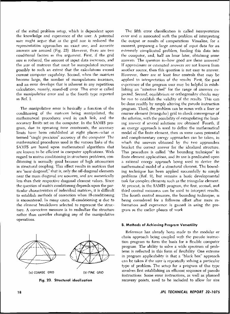
of the initial problem setup, which is dependent uponthe knowledge and experience of the user. A potentialuser might argue that as the grid size is reduced therepresentation approaches an exact one, and accurateanswers are assured (Fig. 23) However, there are twoconditional factors in this argument. First, if the gridsize is reduced, the amount of input data increases, andthe size of matrices that must be manipulated increasepossibly to such an extent that the calculations exceedcurrent computer capability. Second, when the matricesbecome large, the number of manipulations increases,and an error develops that is inherent in any repetitiouscalculation, namely, round-off error This error is calledthe manipulative error and is the fourth type reportedin Ref. 1.
The manipulative error is basically a function of theconditioning of the matrices being manipulated, themathematical procedures used in each link, and theaccuracy limits set on the computer. In the SAMIS pro-gram, due to operating time constraints, the accuracylimits have been established at eight places—what istermed "single precision" accuracy of the computer Themathematical procedures used in the various links of theSAMIS are based upon mathematical algorithms thatare known to be efficient in computer applications. Withregard to matrix conditioning in structures problems, con-ditioning is normally good because of high attenuationin structural coupling. This effect results in matrices thatare "near diagonal," that is, only the off-diagonal elementsnear the main diagonal are nonzero, and are numericallyless than their respective diagonal element values. Sincethe question of matrix conditioning depends upon the par-ticular characteristics of individual matrices, it is difficultto establish methods of correction when ill-conditioningis encountered. In many cases, ill-conditioning is due tothe element breakdown selected to represent the struc-ture. A corrective measure is to reidealize the structurerather than consider changing any of the manipulativeoperations.
(a) COARSE GRID (b) FINE GRID
Fig. 23. Structural idealization
The fifth error classification is called interpretationeiror and is associated with the problem of interpretingthe output or results of computations Visualize, for amoment, preparing a large amount of input data for anextremely complicated problem, feeding this data intothe computer, and, half an hour later, obtaining someanswers The question is—how good are these answers?If approximate or estimated answers are not known fromanother source, then this question is not easy to answer.However, there are at least four controls that may beapplied to intequretation of the results First, the pastexperience of the program user may be helpful in estab-lishing an "intuitive feel" for the range of answers ex-pected. Second, equilibrium or orthogonality checks maybe run to establish the validity of the results This canbe done readily by simply altering the pseudo instructionprogram. Third, the problem can be rerun with a finer orcoarser element (triangular) grid to check convergence ofthe solution, with the possibility of extrapolating the limit-ing answer if several solutions are obtained Fourth, ifan energy approach is used to define the mathematicalmodel of the finite element, then in some cases potentialand complementary energy approaches can be taken, inwhich the answers obtained by the two approachesbracket the correct answer for the idealized structure.This procedure is called "the bounding technique" infinite element applications, and its use is predicated upona rational energy approach being used to derive themathematical model of a structural element. The bound-ing technique has been applied successfully to simpleproblems (Ref. 9), but remains a basic developmentaltask for complex elements such as the triangular element.At present, in the SAMIS program, the first, second, andthird control measures can be used to interpret results.The fourth control measure, the bounding technique, isbeing considered for a followon effort after more in-formation and experience is gained in using the pro-gram in the earlier phases of work
B. Methods of Achieving Program Versatility
Reference has already been made to the modular orchain approach being coupled with the pseudo instruc-tion program to form the basis for a flexible computerprogram The ability to solve a wide spectrum of prob-lems is reflected in this form of flexibility One extremein program applicability is that a "black box" approachcan be taken if the user is repeatedly solving a particulartype of problem. The setup for a program of this typeinvolves first establishing an efficient sequence of pseudoinstructions Some error instructions, as well as plannedrecovery points, need to be included to allow for size
18 JPL TECHNICAL REPORT 32-1075
variations in input data and recovery from computerterminating errors Once the program is set up andchecked out, the user is merely instructed on input-output\vriteup and interpretation and on recovery procedures.With this approach, the user need not know matrixalgebra even though matrices may be required input.In the SAMIS program, because the matrix coding systemis related to the structural idealization, the input matriceshave the appearance of tabulated data, and interpreta-tion is possible without explicit use of the word "matrix."The output data is also printed in tabular form, and anunderstanding of the meaning of the codes that accom-pany each element value is sufficient for interpretation.
The other extreme in program usage is in the solutionof the general matrix problem. Applicability of the SAMISprogram to solve general problems is contingent upon thefunctions performed by the manipulative links. Hence,the user must be familiar \\ith matrix algebra and theoptions, capabilities, and limitations of the SAMIS links.By means of this approach, problems in any discipline maybe solved using the SAMIS program, provided the solu-tions can be effected using matrix algebra
In addition to versatility in general matrix-manipulativeapplications, the user will find the SAMIS program versa-tile in structural applications within the limitation of theelements in the program. Some of the options availableto the structural analyst are the following:
(1) Selection of elastic axes when working with non-isotropic materials.
(2) Use of any of several mass matrix representationsfor each element.
(3) Ability to impose boundary conditions either in theprogram generation link, BILD, or by pre- andpost-matrix multiplication.
(4) Specification of local coordinates for elementsalong which stress resultants are determined.
(5) Idealization of shell stiffness by either co-planar or"off-set" line elements.
(6) Selection of coordinates along which deflectionsare referenced
(7) Use of program-generated loading vectors for pres-sure and temperature induced loads.
(8) Complete freedom to "mix" element types in ideali-zation of composite structures.
(9) Ability to interpolate and/or extrapolate materialphysical parameters as a function of materialtemperature.
(10) Ability to represent displacement and force dis-continuities at structural joints.
The ease of incorporating extensions and modificationsinto the SAMIS program is also an important form of sys-tem flexibility There are two areas where this form offlexibility is needed First, the modular format of theprogram library allows for addition of new links by merelyidentifying the program in the master intelligence systemfor pseudo instruction interpretation and assigning a chainnumber to the subprogram for locating it on the librarytape The other area where expansion is likely is in thegeneration subprogram library of stiffness elementsExpansion problems in this area center on changes in theinput data However, the input data format of the SAMISprogram has been planned and set up so that any typeof element, including the three-dimensional solid, can beput in the library without format changes.
C. Methods of Insuring Program Reliability
The type of reliability of concern here is that associatedwith the functioning of the entire program. Since a com-puter program is merely a set of instructions that thecomputer is slaved to follow, once all of the logic and flowoptions in the instructions have been tested and provento be correct, reliability is assured in the sense that a sub-mitted problem will be properly executed. The onlyvariants are the validity of the input data and the mal-functioning of the computer itself.
For large programs such as the SAMIS, containingnumerous flow patterns and options, checkout is an exten-sive effort In the checkout of the SAMIS program threelevels of problems were generated and run. The functionof the first level of problems was to establish the rationaleof the logic within each link. Next, with the links groupedin a chain library, the second level of problems checkedthe compatibility between links (in various sequences).Finally, because the program was designed to manipulatelarge blocks of data that could fill and exceed core, check-out of program capacity dictated the third level of testproblems
It was recognized that one comprehensive test problemcould not be formulated that would check all options ofthe SAMIS. Therefore, a support effort was planned andsubsequently integrated with overall program develop-ment. This activity by JPL personnel was intended to aid
JPL TECHNICAL REPORT 32-1075 19
VVDL in certain critical areas and orient JPL personnel ondetails of the program functions and operations In addi-tion to the checkout effort already described, this supportfunction involved the following participation by JPL tech-nical representatives- weekly technical meetings with\VDL personnel to discuss any matters relating to programdevelopment, review of technical and programming docu-ments as they were generated during development, andparticipation in writeup of some of the key segments ofthe SAMIS program. During this checkout phase, JPLassigned from one to three engineeis and one programmeras needed to perform the various functions In retrospect,it is felt that this support effort not only effectivelyoriented the JPL technical personnel in understanding theSAMIS program operation but served also as a check andbalance to increase the reliability and to speed up thecheckout of the program '
Checkout of system manipulative links proceeded withthe normal types of errors causing difficulty Some pro-gram features were very useful in checkout, particularlythe recovery feature Cross checking of different link-outputs was advantageously used. For example, the out-put from the links used to solve simultaneous equations(CHOL, ITER) was compared to the matrix decomposi-tion link (CHIN) by proper selection of the set ofequations. Vector orthogonality and matrix symmetrychecks, core dump and data tape analyses and otherstandard techniques were used to check the logic and flowof the program
The other phase of the program, the generation pack-age, was the source of two fundamental problems thatimpeded system checkout derivation of an adequatetriangular element representation and the rational distri-bution of gridpoint forces over each triangle to obtainaccurate stress values The problems associated with thetriangular element representation have already been dis-cussed briefly in this section. Although displacementvalues can be determined very accurately (Ref 3), the
'Several activities resulted from JPL participation to complementtrie primary work on program development For example, JPLdocumentation of the test problem input data and .solution sup-plements the technical and usage reports prepared by WDLDuring program checkout, additional small test problems weresubmitted by JPL personnel to verify the operation and flou ofcertain program options not tested by the comprehensive testproblems Tn having the opportunity to review the technicalaspects of the methods used in the SAMIS program, JPL personnelhave been able to initiate supporting development and researchprojects and to better plan the direction that should be taken toextend and improve the SAMIS program to meet future analysisneeds
determination of accurate stresses is a well-recognizedproblem in finite element methods, and for many elementtypes no exact procedure is available. Methods for com-puting stress resultants for the triangular element wereinvestigated at JPL, and the results of this work arereported in Ref. 10 The method for computing stressresultants in the SAMIS program are outlined in Ref. 1.
VI. The Engineering Function in StructuralAnalyses with the SAMIS Program
As is true in any computer program, a certain amountof basic data must be supplied to the system to initiatethe generation and solution routines Understandably,since the elements used in shell-structure idealizationsare more complicated than, say, the beam elements usedin frame-structure analyses, the amount of input data forthe SAMIS program exceeds that of corresponding frameanalysis programs. In fact, the beam, bar, and torque-tubeelements, which are types of elements needed in the analy-sis of frame structures, are a part of the element library inthe SAMIS program, and so constitute a fractional part ofthe total input specification
In general, the procedures involved in establishing inputfor frame-type structures are well known, so emphasis willbe placed here on the problems of input preparation forshell-type structures. In setting up a shell-type problemfor the computer, one of the first tasks of the analyst is toestablish a triangular array that adequately represents thecharacteristics of the structure. This must be done withinthe constraints on matrix size and, consequently, mayinvolve the use of: structural planes of symmetry, localrefinements in triangular grid sizes, modal convergencetechniques, mathematical partitioning, and other methodsto avoid bulky manipulative operations. Once the tri-angular grid is established, the next step is to number thegndpoints. This step is extremely important, since thematrix row-bandwidths are established by the nature ofthe numbering sequence In general the optimal arrange-ment is that in which adjacent gridpomts have numbersthat are close in value. Procedures for testing the'qualityof particular gridpoint numbering arrangements are givenin Ref 1. These procedures have been defined thoroughlyin order that this calculation can be performed byengineering-aide personnel. After the triangular grid andgridpoint numbering sequence have been defined, theelement input data can be prepared, also by engineering-aide personnel
The tasks remaining for the engineer are to select theappropriate set of pseudo instructions and to write the
20 JPL TECHNICAL REPORT 32-1075
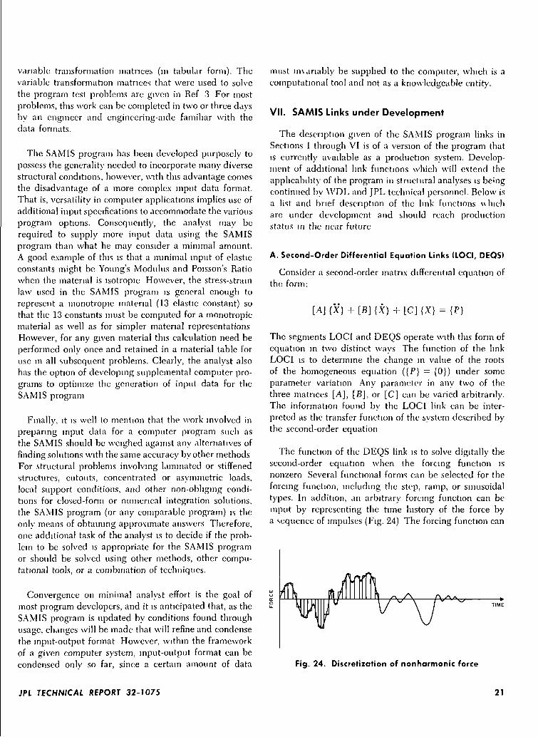
variable transformation matrices (in tabular form). Thevariable transformation matrices that were used to solvethe program test problems arc given in Ref 3 For mostproblems, this work can be completed in two or three daysby an engineer and engineering-aide familiar with thedata formats.
The SAMIS program has been developed purposely topossess the generality needed to incorporate many diversestructural conditions, however, with this advantage comesthe disadvantage of a more complex input data format.That is, versatility in computer applications implies use ofadditional input specifications to accommodate the variousprogram options. Consequently, the analyst may berequired to supply more input data using the SAMISprogram than what he may consider a minimal amount.A good example of this is that a minimal input of elasticconstants might be Young's Modulus and Poisson's Ratiowhen the material is isotropic However, the stress-strainlaw used in the SAMIS program is general enough torepresent a monotropic material (13 elastic constant) sothat the 13 constants must be computed for a monotropicmaterial as well as for simpler material representationsHowever, for any given material this calculation need beperformed only once and retained in a material table foruse in all subsequent problems. Clearly, the analyst alsohas the option of developing supplemental computer pro-grams to optimize the generation of input data for theSAMIS program
Finally, it is well to mention that the work involved inpreparing input data for a computer program such asthe SAMIS should be weighed against any alternatives offinding solutions with the same accuracy by other methodsFor structural problems involving laminated or stiffenedstructures, cutouts, concentrated or asymmetric loads,local support conditions, and other non-obliging condi-tions for closed-form or numerical integration solutions,the SAMIS program (or any comparable program) is theonly means of obtaining approximate answers Therefore,one additional task of the analyst is to decide if the prob-lem to be solved is appropriate for the SAMIS programor should be solved using other methods, other compu-tational tools, or a combination of techniques.
Convergence on minimal analyst effort is the goal ofmost program developers, and it is anticipated that, as theSAMIS program is updated by conditions found throughusage, changes will be made that will refine and condensethe input-output format However, within the frameworkof a given computer system, input-output format can becondensed only so far, since a certain amount of data
must imanably be supplied to the computer, which is acomputational tool and not as a knowledgeable entity.
VII. SAMIS Links under Development
The description given of the SAMIS program links inSections 1 through VI is of a version of the program thatis currently available as a production system. Develop-ment of additional link functions which will extend theapplicability of the program in structural analyses is beingcontinued by WDL and JPL technical personnel. Below isa list and brief description of the link functions \\lncliare under development and should reach productionstatus in the near future
A. Second-Order Differential Equation Links (LOCI, DEOS)
Consider a second-order matrix differential equation ofthe form:
[A] {X} + [B] {X} + [C] {X} = {P}
The segments LOCI and DEQS operate with this form ofequation in two distinct ways The function of the linkLOCI is to determine the change in value of the rootsof the homogeneous equation ({P} = {0}) under someparameter variation Any parameter in any two of thethree matrices [A], [B], or [C] can be varied arbitrarily.The information found by the LOCI link can be inter-preted as the transfer function of the system described bythe second-order equation
The function of the DEQS link is to solve digitally thesecond-order equation when the forcing function isnonzero Several functional forms can be selected for theforcing function, including the step, ramp, or sinusoidaltypes. In addition, an arbitrary forcing function can beinput by representing the time history of the force bya sequence of impulses (Fig. 24) The forcing function can
Fig. 24. Discretization of nonharmonic force
JPL TECHNICAL REPORT 32-1075 21
be an actual force, a specification of defined displace-ments, or accelerations acting on the system. Both theLOCI and DEQS links are limited to matrices of 40thorder or less The Muller method is used to isolate theroots in the LOCI link and the Runge-Kutta method isused to perform the integration in the DEQS link
Increasing analysis capability beyond the 40-degree-of-freedom limit for forced-response prediction is underdevelopment, but will not be completed in the nextyear. This extension incorporates the method of compo-nent mode synthesis to analyze complex structures(Ref. 11 and 12).
B. Extended Choleski Decomposition Link(CHOL, Modified)
The same basic matrix manipulations performed by thecurrent CHOL will be performed also by extended CHOL.The difference in capability between the two is that theextended version will solve simultaneous equations whosediagonal and upper off-diagonal coefficient matrix canexceed core size. Thus, using extended CHOL, a set ofsimultaneous equations of any order can be solved, theonly limitation being that the row-halfband width mustbe less than 200 elements. For structural applications thislimitation is not severe.
The basic difference between the two links is that, whileboth versions require two passes through the coefficientmatrix to form the triangular decomposition, the currentCHOL link requires that this decomposition fit in corewhile the extended CHOL link stores the triangulardecomposition on tape The extended CHOL link mustthen pass piecewise through the decomposition twice foreach solution to the set of simultaneous equations, onceto perform a forward substitution for an intermediatesolution and once for a back substitution to obtain thefinal solution.
C. Buckling Load Prediction Links (BILD, SMAD)
These special links support the capability to predict thesmall-deflection buckling loads. The BILD link is modi-fied to develop stiffness matrices which are a function ofinternal loads. In general, the equation to define bucklingloads is given by
,6
where
[K] is the stiffness matrix of the stress-free structure
{<•/} is the vector of gridpomt displacements
A is the unknown scalar multiplier. It defines thefactor by which the prestress-state stresses mustbe multiplied to induce small deflection buckling
a, are the generalized stresses for each element
[K1] are the stiffness matrix corrections accounting forfirst order large deflection effects.
The SMAD link provides the capability to easily formthe matrix scalar multiplications and summation indicatedin forming the incremental stiffness matrix in the equationabove. The a, scalars may be introduced directly or ob-tained by multiplying a set of displacements by the stressmatrices. These displacements can also be found by solv-ing for a particular loading Then the scalar A representsthe factor by which the loads must be multiplied for buck-ling to occur. The SMAD link provides a serial and wave-front capability like that of the ADDS link.
D. Root Extractor Link (POWR)
This link uses the power method to determine the fun-damental root and associated vector of a square, sym-metric matrix. The matrix is limited to in-core sizes, in thesense that only the diagonal and upper off-diagonal ele-ments in variable bandwidth must fit in core. This link isintended to provide the capability to obtain roots andvectors for systems of approximately 500th order whenthe matrix is symmetric and sparse
E. Input Data Error Diagnostic Link (CHEX)
An error diagnostic link to detect errors in input datais under development to aid in minimizing the computerrunning time per problem. Currently, submittal of data tothe computer for a problem-solving run can be a costlyoperation if the input data contains errors For some typesof errors, particularly in the pseudo instruction program,only one error per run will be detected and diagnosticprintout given. To alleviate this problem, a data checkinglink, CHEX, is being developed. This link is designed tooperate on the IBM 7094 as a chain routine that can becalled in the same manner as other links. In additionCHEX is coded to be operational as a separate diagnosticpackage on the IBM 1620 computer with disk filing. Thisprovision allows the checkout of input data decks atreduced cost on the IBM 1620 prior to running the prob-lem on the IBM 7094 to obtain a solution. The CHEX link-is a two-segment program that can detect most major
22 JPL TECHNICAL REPORT 32-1075
errors in an input data deck CHEX \\ill have an appro-priate library of comment statements that indicate thenature of each error detected
F. Conical Element Generation Routines (CONE)
For structural analysis of shells of revolution and cir-cular plates, the recently developed truncated-cone finiteelement can be used to advantage The conditions onloading states for this element are that the distributionbe representable by a Fourier series about a circumfer-ence. The series may be either symmetric, asymmetric, ora combination of each with respect to the rotational axisof the shell For each harmonic of the series, separate stiff-
ness, stress, and loading matrices are generated. This ele-ment when operational in BILD, will be the third basicelement-type in the program library.
Theoretical basis for the element is presented in Refs. 13,14, and 15 Numerical results from idealizations of severalshell-type structures with the conical element are also pre-sented in these references.
Future modifications will change the conical shell ele-ment equation generation routine to provide a number ofarbitrarily-spaced joints on the cone periphery in orderthat line and facet elements may be joined to it.
References
1. Melosh, R. J., and Christiansen, H. N., Structural Analysis and Matrix Interpre-tative System (SAMIS) Program: Technical Report, Jet Propulsion Laboratory,Pasadena, California, Technical Memorandum 33-311, November 1, 1966
2. Melosh, R. J., et al, Structural Analysis and Matrix Interpretative System(SAMIS) Program Report Revision 1, Jet Propulsion Laboratory, Pasadena,California, Technical Memorandum 33-307, December 15, 1966
3. Lang, T. E, Structural Analysis and Matrix Interpretative System (SAMIS)User Report, Jet Propulsion Laboratory, Pasadena, California, Technical Memo-randum 33-305, March 1,1967.
4. Archer, J. S., "Consistent Mass Matrix for Distributed Mass Systems," Ameri-can Society of Civil Engineers, Structures Journal, Vol. 89, pp. 161-178,August 1963.
5. Melosh, R. J., and Lang, T. E., "Modified Potential Energy Mass Representa-tions For Frequency Prediction," Paper Presented at Conference on "MatrixMethods in Structural Mechanics," Wright-Patterson Air Force Base, Ohio,October 26-28, 1965
6. Leckie, F. A., and Lindberg, G. M., "The Effect of Lumped Parameters onBeam Frequencies," Aeronautical Quarterly, Vol. XIV, Part 3, pp. 224-240,August 1963.
7. Melosh, R. J., "A Flat Triangular Shell Element Stiffness Matrix," PaperPresented at Conference on "Matrix Methods in Structural Mechanics," Wright-Patterson Air Force Base, Ohio, October 26-28, 1965.
8. Utku, Senol, "Stiffness Matrices for Thin Triangular Elements of Non-ZeroGaussian Curvature," AIAA Paper No. 66-530, Fourth Aerospace SciencesMeeting, Los Angeles, California, June 1966.
JPL TECHNICAL REPORT 32-1075 23
References (contd)
9. Melosh, R. }., Development of the Stiffness Method to Define Bounds on ElasticBehavior of Structures, University of Washington, Ph.D Thesis, August 1962,Seattle, Wash.
10. Utku, Senol, Computation of Stresses in Triangular Finite Elements, JetPropulsion Laboratory, Pasadena, California, Technical Report 32-948,June 15, 1966.
11. Hurty, W. C., "Dynamic Analysis of Structural Systems Using ComponentModes," American Institute of Aeronautics and Astronautics Journal, Vol. 3,pp. 678-685, 1965.
12. Bamford, R M., A Modal Combination Program for Dynamic Analysis ofStructures, Jet Propulsion Laboratory, Pasadena, California, Technical Memo-randum 33-290, August 15, 1966.
13. Percy, J. H., Pian, T. H. H , Klein, S , and Navaratna, D. R., "Application ofMatrix Displacement Method of Linear Elastic Analysis of Shells of Revolu-tions," American Institute of Aeronautics and Astronautics Journal, Vol. 3,pp. 2138-2145, 1965.
14 Grafton, P. E , and Strome, D. R , "Analysis of Axisymmetrical Shells by theDirect Stiffness Method," American Institute of Aeronautics and AstronauticsJournal, Vol 1, pp. 2342-2347,1963.
15. Jones, R. E., and Strome, D R., "Direct Stiffness Method Analysis of Shellsof Revolution Utilizing Curved Elements," American Institute of Aeronauticsand Astronautics Journal, Vol 4, pp 1519-1525, 1966.
24 JPL TECHNICAL REPORT 32-7075