Embed Size (px)
Citation preview

Summary of Safety and Effectivness (SSED)Template Page 1
SUMMARY OF SAFETY AND EFFECTIVENESS DATA (SSED) I. GENERAL INFORMATION
Device Generic Name: Stimulator, Carotid Sinus
Device Trade Name: BAROSTIM NEO® System
Device Procode: DSR
Applicant’s Name and Address: CVRx, Inc. 9201 West Broadway Avenue, Suite 650 Minneapolis, Minnesota 55445
Date(s) of Panel Recommendation: None
Premarket Approval Application (PMA) Number: P180050
Date of FDA Notice of Approval: August 16, 2019
Breakthrough Device: Granted breakthrough device status (formerly known as the Expedited Access Pathway, or EAP) on June 25, 2015 because the device met two criteria for addressing an unmet need: (1) no appropriate alternative, and (2) the availability of the device is in the best interest of patients.
II. INDICATIONS FOR USE
The BAROSTIM NEO® System is indicated for the improvement of symptoms of heart failure – quality of life, six-minute hall walk and functional status, for patients who remain symptomatic despite treatment with guideline-directed medical therapy, are NYHA Class III or Class II (who had a recent history of Class III), have a left ventricular ejection fraction ≤ 35%, a NT-proBNP < 1600 pg/ml and excluding patients indicated for Cardiac Resynchronization Therapy (CRT) according to AHA/ACC/ESC guidelines.
III. CONTRAINDICATIONS
Patients are contraindicated if they have: Been assessed to have bilateral carotid bifurcations located above the level of the
mandible Baroreflex failure or autonomic neuropathy Uncontrolled, symptomatic cardiac bradyarrhythmias Carotid atherosclerosis that is determined by ultrasound or angiographic evaluation
greater than 50% Ulcerative plaques in the carotid artery as determined by ultrasound or angiographic
evaluation Known allergy to silicone or titanium
Summary of Safety and Effectivness (SSED)Template Page 2
IV. WARNINGS AND PRECAUTIONS
The warnings and precautions can be found in the BAROSTIM NEO System labeling. V. DEVICE DESCRIPTION
The BAROSTIM NEO System includes the following components:
Device Model(s) Implantable Pulse Generator (IPG): IPG Torque Wrench Port Plug
2102
Carotid Sinus Lead (CSL) Kit*: Lead (Model 1036 or 1037) Implant Adapter (Model 5033) Implant Tool (Model 5031)
1036 & 1037
Programmer System (CPS): Computer/Software Programmer Interface (PI)
9010
Carotid Sinus Lead (CSL) Repair Kit CSL Repair Kit Lead/Tool Torque Wrench, Tubing
5010
* There are 2 possible kit combinations. A kit is selected based on the CSL length that is needed: long (Model 1037) or short (Model 1036). Each kit contains an Implant Tool (Model 5031) and Implant Adapter (Model 5033).
Figure 1: BAROSTIM NEO System (excluding Implant Adapter and Implant Tool) The BAROSTIM NEO System is the CVRx next generation system for improving cardiovascular function. The minimally-invasive BAROSTIM NEO System uses CVRx patented BAROSTIM THERAPY® technology to trigger the body’s own natural systems by electrically activating the carotid baroreceptors, the body’s natural cardiovascular regulation
Summary of Safety and Effectivness (SSED)Template Page 3
sensors. In conditions such as hypertension and heart failure it is believed the baroreceptors, the body’s natural sensors, are not functioning properly and are not sending sufficient signals to the brain. This results in the brain sending signals to other parts of the body (heart, blood vessels, kidneys) to constrict the blood vessels, retain water and salt by the kidneys and increase stress-related hormones. When the baroreceptors are activated, signals are sent through neural pathways to the brain. In response, the brain works to counteract this stimulation by sending signals to other parts of the body (heart, blood vessels, and kidneys) that relax the blood vessels and inhibit the production of stress-related hormones. These changes act to reduce after-load and enable the heart to increase blood output, while maintaining or reducing its workload. Implantable Pulse Generator (IPG)
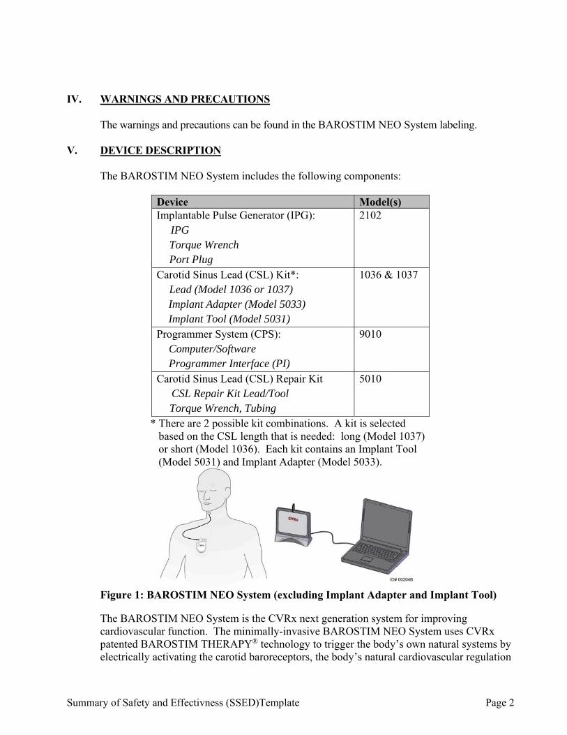
The Model 2102 IPG (Figure 2) contains a battery and circuitry in a hermetic enclosure. It provides control and delivery of the activation energy through the Carotid Sinus Lead to the baroreceptors. The carotid sinus lead is attached to the pulse generator through the connector module. Nominal dimensions for the IPG are listed in Figure 2.
Parameter Max
Value Height 72 mm Width 50 mm Thickness 14 mm Mass 60
grams Volume 40cc
Figure 2: Implantable Pulse Generator
Carotid Sinus Leads (CSL)
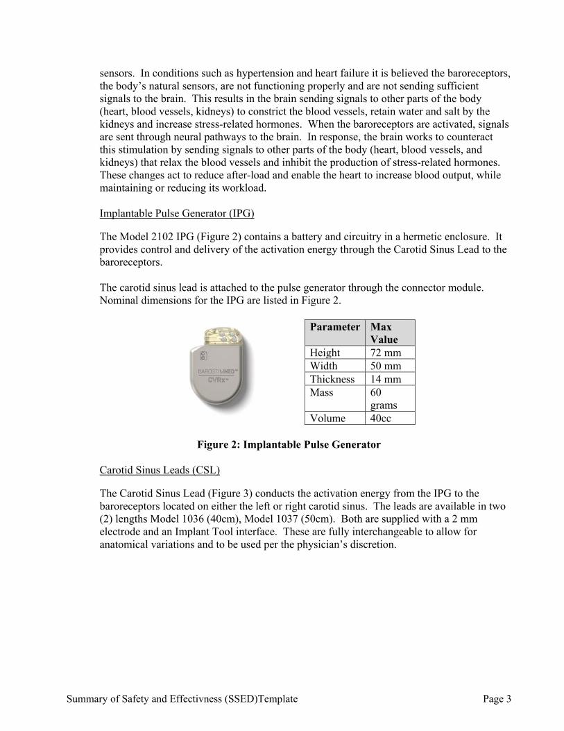
The Carotid Sinus Lead (Figure 3) conducts the activation energy from the IPG to the baroreceptors located on either the left or right carotid sinus. The leads are available in two (2) lengths Model 1036 (40cm), Model 1037 (50cm). Both are supplied with a 2 mm electrode and an Implant Tool interface. These are fully interchangeable to allow for anatomical variations and to be used per the physician’s discretion.
Summary of Safety and Effectivness (SSED)Template Page 4
Figure 3: Carotid Sinus Lead
Implant Adapter
The Model 5033 Implant Adapter is a temporary device used at system implant during the electrode mapping process. The therapy circuit requires two connections; the therapy lead and the IPG case. The implant adapter connects the therapy lead directly to the IPG header port and the case connection is made via a clip placed on the IPG surface.
Model 5033 Adapter
Figure 4: Implant Adapter
Implant Tool
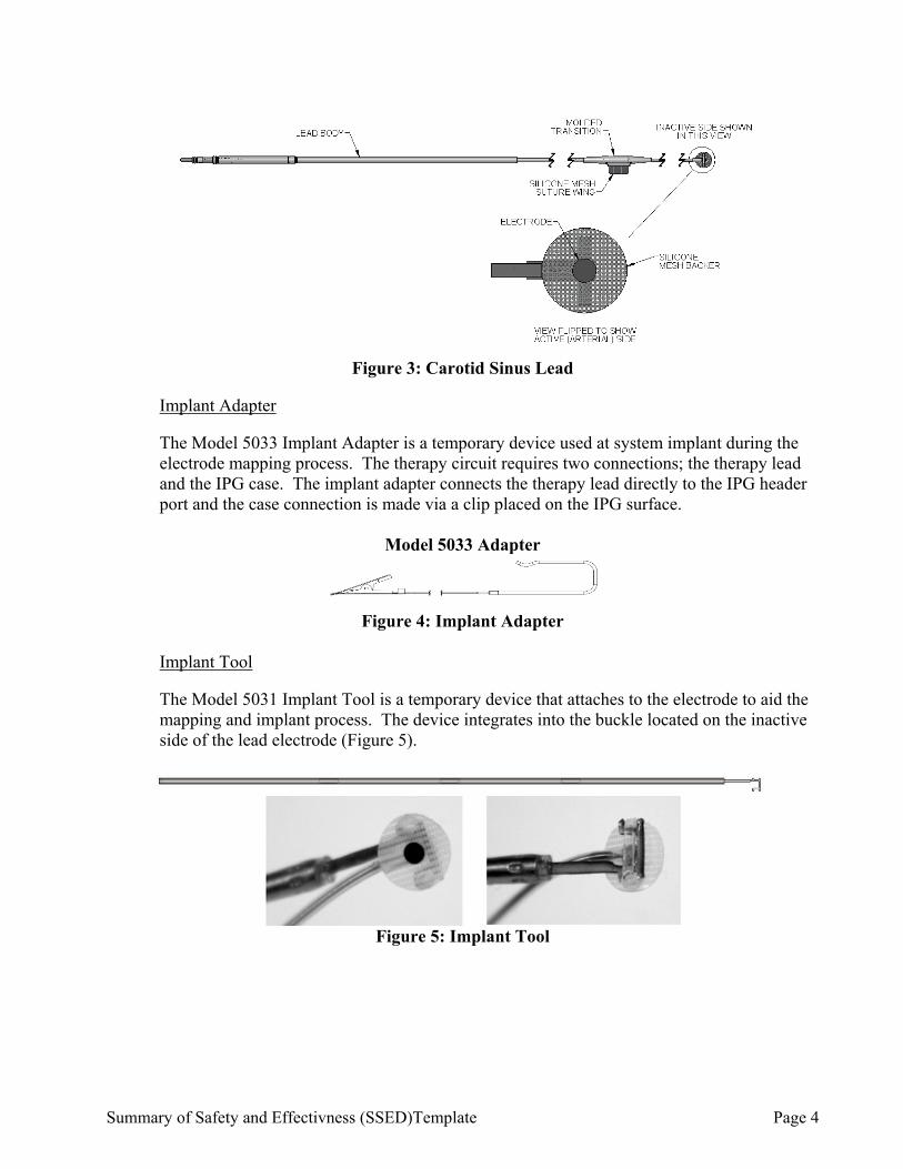
The Model 5031 Implant Tool is a temporary device that attaches to the electrode to aid the mapping and implant process. The device integrates into the buckle located on the inactive side of the lead electrode (Figure 5).
Figure 5: Implant Tool
Summary of Safety and Effectivness (SSED)Template Page 5
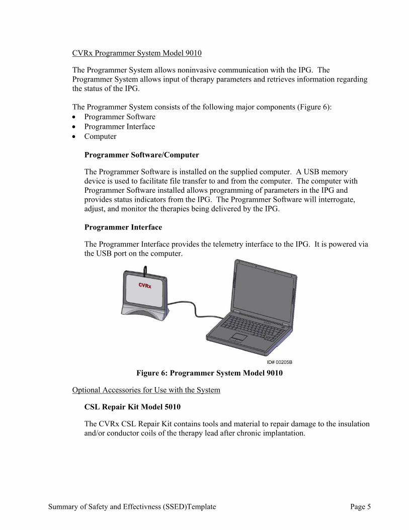
CVRx Programmer System Model 9010
The Programmer System allows noninvasive communication with the IPG. The Programmer System allows input of therapy parameters and retrieves information regarding the status of the IPG. The Programmer System consists of the following major components (Figure 6): Programmer Software Programmer Interface Computer
Programmer Software/Computer
The Programmer Software is installed on the supplied computer. A USB memory device is used to facilitate file transfer to and from the computer. The computer with Programmer Software installed allows programming of parameters in the IPG and provides status indicators from the IPG. The Programmer Software will interrogate, adjust, and monitor the therapies being delivered by the IPG.
Programmer Interface
The Programmer Interface provides the telemetry interface to the IPG. It is powered via the USB port on the computer.
Figure 6: Programmer System Model 9010
Optional Accessories for Use with the System
CSL Repair Kit Model 5010
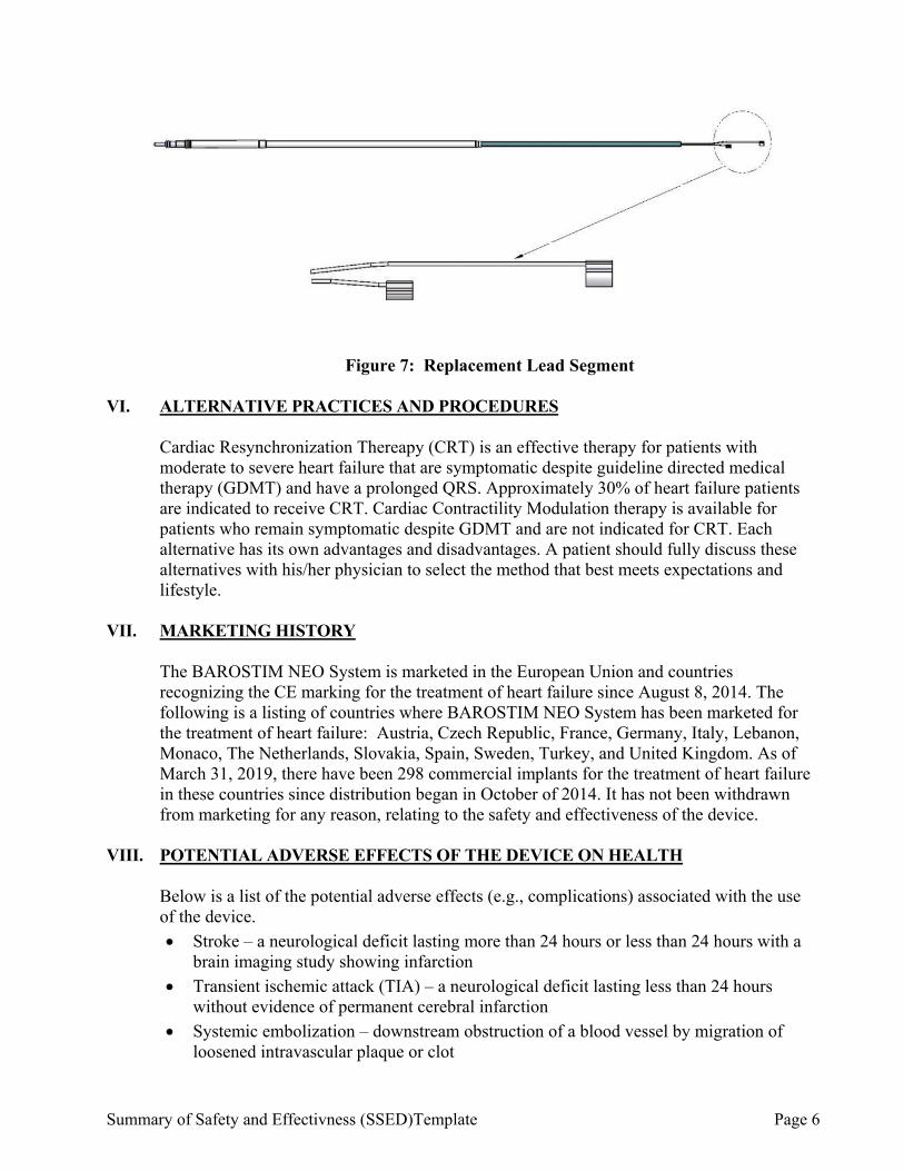
The CVRx CSL Repair Kit contains tools and material to repair damage to the insulation and/or conductor coils of the therapy lead after chronic implantation.
Summary of Safety and Effectivness (SSED)Template Page 6
Figure 7: Replacement Lead Segment
VI. ALTERNATIVE PRACTICES AND PROCEDURES
Cardiac Resynchronization Thereapy (CRT) is an effective therapy for patients with moderate to severe heart failure that are symptomatic despite guideline directed medical therapy (GDMT) and have a prolonged QRS. Approximately 30% of heart failure patients are indicated to receive CRT. Cardiac Contractility Modulation therapy is available for patients who remain symptomatic despite GDMT and are not indicated for CRT. Each alternative has its own advantages and disadvantages. A patient should fully discuss these alternatives with his/her physician to select the method that best meets expectations and lifestyle.
VII. MARKETING HISTORY
The BAROSTIM NEO System is marketed in the European Union and countries recognizing the CE marking for the treatment of heart failure since August 8, 2014. The following is a listing of countries where BAROSTIM NEO System has been marketed for the treatment of heart failure: Austria, Czech Republic, France, Germany, Italy, Lebanon, Monaco, The Netherlands, Slovakia, Spain, Sweden, Turkey, and United Kingdom. As of March 31, 2019, there have been 298 commercial implants for the treatment of heart failure in these countries since distribution began in October of 2014. It has not been withdrawn from marketing for any reason, relating to the safety and effectiveness of the device.
VIII. POTENTIAL ADVERSE EFFECTS OF THE DEVICE ON HEALTH
Below is a list of the potential adverse effects (e.g., complications) associated with the use of the device.
Stroke – a neurological deficit lasting more than 24 hours or less than 24 hours with a brain imaging study showing infarction
Transient ischemic attack (TIA) – a neurological deficit lasting less than 24 hours without evidence of permanent cerebral infarction
Systemic embolization – downstream obstruction of a blood vessel by migration of loosened intravascular plaque or clot
Summary of Safety and Effectivness (SSED)Template Page 7
Surgical or anesthetic complications
Infection – the need for antibiotics or possible removal of the BAROSTIM NEO System
Wound complication – including hematoma (i.e. bruising and/or swelling)
Arterial damage – including carotid artery rupture or hemorrhage (sudden and significant blood loss at a site of blood vessel rupture that may require reoperation or transfusion)
Pain – an unpleasant sensory experience, including neck and chest pocket pain Nerve damage/stimulation – including injury to or stimulation of Cranial, Marginal
Mandibular, Glossopharyngeal, Recurrent Laryngeal, Vagus and Hypoglossal Nerves (numbness in head and neck, facial palsy/paralysis, altered speech, altered sense of taste, respiratory constriction, stertorous breathing, excessive salivation, dry cough, vomiting and/or regurgitation, altered sensory and motor function of tongue, altered sensory function of pharynx and oropharynx, altered sensation in external auditory canal), stimulation of extravascular tissue [muscle twitching (fasciculation), pain, tingling, oral sensations]
Hypotension – a decrease in systolic and diastolic blood pressure below normal levels that may result in dizziness, fainting, and/or falls
Hypertensive crisis – uncontrolled rise in blood pressure
Respiratory – including low oxygen saturation, respiratory distress, shortness of breath
Exacerbation of heart failure
Cardiac arrhythmias
Tissue erosion/IPG migration – movement of device resulting in need for reoperation
Injury to baroreceptors – an injury that results in baroreflex failure Fibrosis – replacement of normal tissue by the ingrowth of fibroblasts and the
deposition of connective tissue
Allergic reaction
General injury to user or subject – may be due to surgical procedure, device use, or interaction with other devices
Need for reoperation – operation to explant/replace IPG or CSLs due to tissue damage, infection, and/or device failure
Secondary operative procedure – An increase in the complexity and risk of secondary operative procedures of the neck due to scar tissue and the presence of prosthetic material implanted for this device
Exacerbation of heart failure
Cardiac arrhythmias
Death For the specific adverse events that occurred in the clinical studies, please see Section X below.

Summary of Safety and Effectivness (SSED)Template Page 8
IX. SUMMARY OF NONCLINICAL STUDIES
A. Laboratory Studies The results of bench testing follows below, beginning with the IPG, followed by the CSL lead, programmer and accessories. 1. BAROSTIM NEO IPG Mechanical Bench Tests
Successful testing of the IPG Hardware was completed and is summarized in the tables below, including acceptance criteria, sample size tested and results.
Table 1: IPG Mechanical Test Summary
Specification Feature Test Method Acceptance Criteria Sample Size
Results
Dimensions, Volume, Mass, Device Sharpness / Roughness, Device Marking, Radiopaque Identifier (X-ray ID), Header Configuration
IPG Dimensional, Mass, Marking Verification and Visual Tests
Dimensional: Device height, width, and thickness shall be less than 72mm, 50mm, and 14mm, respectively.
Volume: Device volume shall be less than 40cc. Mass: Device mass shall be less than 60g. Sharpness/Roughness: No external radius shall be less than 1.5mm
excluding seal plug boss features, header overlap, adhesive filled recesses, lead bores, or suture holes. Device shall have a matte finish.
Device Marking: The company name, model, and serial number shall be marked on the device verified by inspection and a wet rub test.
Radiopaque Identifier: The devices shall have a unique radiopaque identifier for IPG including company logo and model.
Header Configuration: Connector cavity shall have two ports appropriately connected and marked left/right.
1 of each model
Pass
Summary of Safety and Effectivness (SSED)Template Page 9
Specification Feature Test Method Acceptance Criteria Sample Size
Results
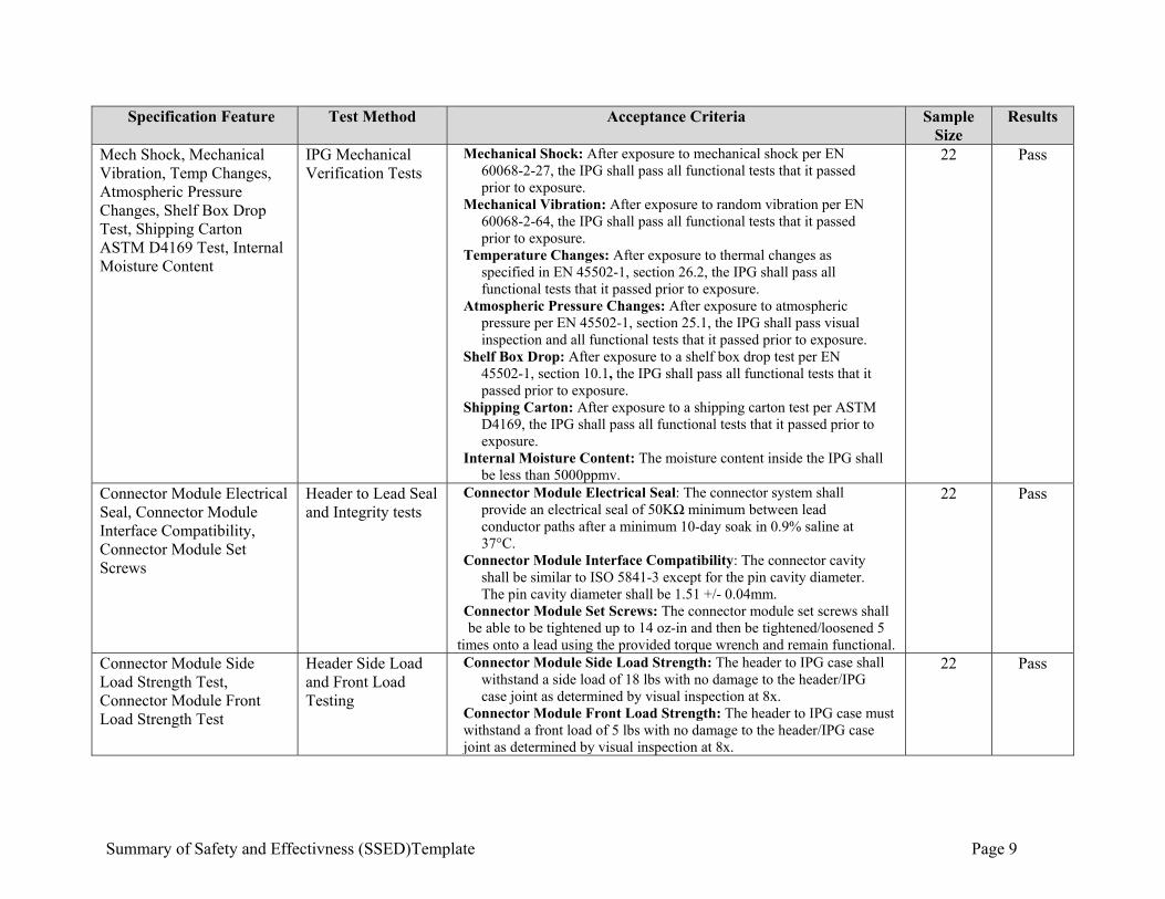
Mech Shock, Mechanical Vibration, Temp Changes, Atmospheric Pressure Changes, Shelf Box Drop Test, Shipping Carton ASTM D4169 Test, Internal Moisture Content
IPG Mechanical Verification Tests
Mechanical Shock: After exposure to mechanical shock per EN 60068-2-27, the IPG shall pass all functional tests that it passed prior to exposure.
Mechanical Vibration: After exposure to random vibration per EN 60068-2-64, the IPG shall pass all functional tests that it passed prior to exposure.
Temperature Changes: After exposure to thermal changes as specified in EN 45502-1, section 26.2, the IPG shall pass all functional tests that it passed prior to exposure.
Atmospheric Pressure Changes: After exposure to atmospheric pressure per EN 45502-1, section 25.1, the IPG shall pass visual inspection and all functional tests that it passed prior to exposure.
Shelf Box Drop: After exposure to a shelf box drop test per EN 45502-1, section 10.1, the IPG shall pass all functional tests that it passed prior to exposure.
Shipping Carton: After exposure to a shipping carton test per ASTM D4169, the IPG shall pass all functional tests that it passed prior to exposure.
Internal Moisture Content: The moisture content inside the IPG shall be less than 5000ppmv.
22 Pass
Connector Module Electrical Seal, Connector Module Interface Compatibility, Connector Module Set Screws
Header to Lead Seal and Integrity tests
Connector Module Electrical Seal: The connector system shall provide an electrical seal of 50KΩ minimum between lead conductor paths after a minimum 10-day soak in 0.9% saline at 37°C.
Connector Module Interface Compatibility: The connector cavity shall be similar to ISO 5841-3 except for the pin cavity diameter. The pin cavity diameter shall be 1.51 +/- 0.04mm.
Connector Module Set Screws: The connector module set screws shall be able to be tightened up to 14 oz-in and then be tightened/loosened 5
times onto a lead using the provided torque wrench and remain functional.
22 Pass
Connector Module Side Load Strength Test, Connector Module Front Load Strength Test
Header Side Load and Front Load Testing
Connector Module Side Load Strength: The header to IPG case shall withstand a side load of 18 lbs with no damage to the header/IPG case joint as determined by visual inspection at 8x.
Connector Module Front Load Strength: The header to IPG case must withstand a front load of 5 lbs with no damage to the header/IPG case joint as determined by visual inspection at 8x.
22 Pass

Summary of Safety and Effectivness (SSED)Template Page 10
2. BAROSTIM NEO IPG Electrical Bench Tests
Successful testing of the IPG Hardware was completed and is summarized in the table below, including test method, sample size, tested and results.
Table 2: IPG Electrical Test Summary
Specification Feature Test Method Acceptance Criteria Sample Size Results
Current Drain, Therapy, Measurement System, Device Environmental (EN 45502-1 Section 20.2 Defib testing)
IPG Electrical Verification Test
Current Drain: <38µA with therapy off; <148µA with therapy on at nominal settings.
Therapy: 1.0mA to 20mA amplitude with resolution of 0.1mA and accuracy of +5/-3%.
Measurement System: Lead impedance accuracy of +/-15% within range of 100 to 4500Ω.
Defibrillation Robustness: No loss of functionality after exposure to external defibrillation per EN 45502-1, Section 20.2.
3 Pass
Accelerated Operating Life test IPG Module Electrical Life Testing
Must meet all device requirements after exposure to accelerated life test equivalent to 10 years.
22 Pass
Leakage Current, ESD, Time Variable Magnetic Field, Static Magnetic Field, Electronic Article Surveillance, Ultrasound
IPG Safety Testing Leakage Current: Leakage current in inactive output pathway must be <1µA.
ESD: No loss of functionality after exposure to 2000V electro-static discharge.
Time Variable Magnetic Field: No loss of functionality after exposure to time variable magnetic field per EN 45502-2-1, Section 27.8.
Static Magnetic Field: No loss of functionality after exposure to static magnetic field per EN 45502-2-1, Section 27.7 and ANSI/AAMI PC69.
Electronic Article Surveillance: No loss of functionality after exposure to time variable magnetic field per EAS E3 test protocol.
1 Pass
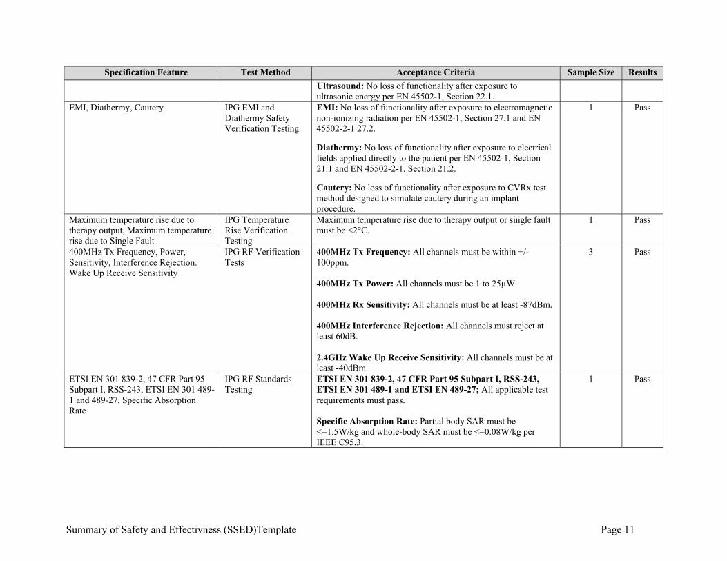
Summary of Safety and Effectivness (SSED)Template Page 11
Specification Feature Test Method Acceptance Criteria Sample Size Results
Ultrasound: No loss of functionality after exposure to ultrasonic energy per EN 45502-1, Section 22.1.
EMI, Diathermy, Cautery IPG EMI and Diathermy Safety Verification Testing
EMI: No loss of functionality after exposure to electromagnetic non-ionizing radiation per EN 45502-1, Section 27.1 and EN 45502-2-1 27.2.
Diathermy: No loss of functionality after exposure to electrical fields applied directly to the patient per EN 45502-1, Section 21.1 and EN 45502-2-1, Section 21.2. Cautery: No loss of functionality after exposure to CVRx test method designed to simulate cautery during an implant procedure.
1 Pass
Maximum temperature rise due to therapy output, Maximum temperature rise due to Single Fault
IPG Temperature Rise Verification Testing
Maximum temperature rise due to therapy output or single fault must be <2°C.
1 Pass
400MHz Tx Frequency, Power, Sensitivity, Interference Rejection. Wake Up Receive Sensitivity
IPG RF Verification Tests
400MHz Tx Frequency: All channels must be within +/- 100ppm. 400MHz Tx Power: All channels must be 1 to 25µW. 400MHz Rx Sensitivity: All channels must be at least -87dBm. 400MHz Interference Rejection: All channels must reject at least 60dB. 2.4GHz Wake Up Receive Sensitivity: All channels must be at least -40dBm.
3 Pass
ETSI EN 301 839-2, 47 CFR Part 95 Subpart I, RSS-243, ETSI EN 301 489-1 and 489-27, Specific Absorption Rate
IPG RF Standards Testing
ETSI EN 301 839-2, 47 CFR Part 95 Subpart I, RSS-243, ETSI EN 301 489-1 and ETSI EN 489-27; All applicable test requirements must pass. Specific Absorption Rate: Partial body SAR must be <=1.5W/kg and whole-body SAR must be <=0.08W/kg per IEEE C95.3.
1 Pass
Summary of Safety and Effectivness (SSED)Template Page 12
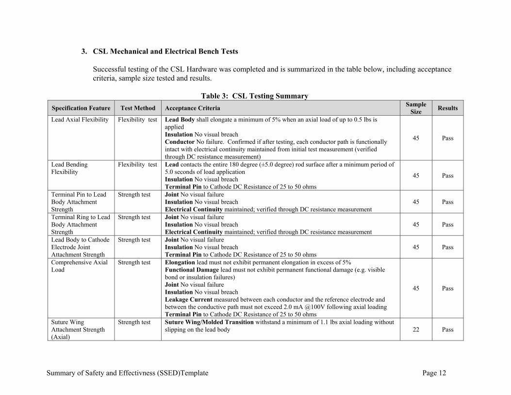
3. CSL Mechanical and Electrical Bench Tests Successful testing of the CSL Hardware was completed and is summarized in the table below, including acceptance criteria, sample size tested and results.
Table 3: CSL Testing Summary
Specification Feature Test Method Acceptance Criteria Sample
Size Results
Lead Axial Flexibility Flexibility test Lead Body shall elongate a minimum of 5% when an axial load of up to 0.5 lbs is applied Insulation No visual breach Conductor No failure. Confirmed if after testing, each conductor path is functionally intact with electrical continuity maintained from initial test measurement (verified through DC resistance measurement)
45 Pass
Lead Bending Flexibility
Flexibility test Lead contacts the entire 180 degree (±5.0 degree) rod surface after a minimum period of 5.0 seconds of load application Insulation No visual breach Terminal Pin to Cathode DC Resistance of 25 to 50 ohms
45 Pass
Terminal Pin to Lead Body Attachment Strength
Strength test Joint No visual failure Insulation No visual breach Electrical Continuity maintained; verified through DC resistance measurement
45 Pass
Terminal Ring to Lead Body Attachment Strength
Strength test Joint No visual failure Insulation No visual breach Electrical Continuity maintained; verified through DC resistance measurement
45 Pass
Lead Body to Cathode Electrode Joint Attachment Strength
Strength test Joint No visual failure Insulation No visual breach Terminal Pin to Cathode DC Resistance of 25 to 50 ohms
45 Pass
Comprehensive Axial Load
Strength test Elongation lead must not exhibit permanent elongation in excess of 5% Functional Damage lead must not exhibit permanent functional damage (e.g. visible bond or insulation failures) Joint No visual failure Insulation No visual breach Leakage Current measured between each conductor and the reference electrode and between the conductive path must not exceed 2.0 mA @100V following axial loading Terminal Pin to Cathode DC Resistance of 25 to 50 ohms
45 Pass
Suture Wing Attachment Strength (Axial)
Strength test Suture Wing/Molded Transition withstand a minimum of 1.1 lbs axial loading without slipping on the lead body 22 Pass
Summary of Safety and Effectivness (SSED)Template Page 13
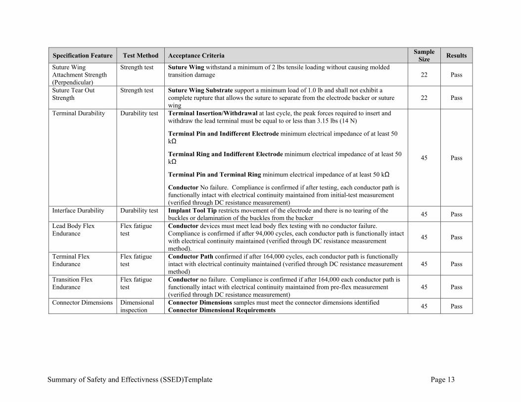
Specification Feature Test Method Acceptance Criteria Sample
Size Results
Suture Wing Attachment Strength (Perpendicular)
Strength test Suture Wing withstand a minimum of 2 lbs tensile loading without causing molded transition damage 22 Pass
Suture Tear Out Strength
Strength test Suture Wing Substrate support a minimum load of 1.0 lb and shall not exhibit a complete rupture that allows the suture to separate from the electrode backer or suture wing
22 Pass
Terminal Durability Durability test Terminal Insertion/Withdrawal at last cycle, the peak forces required to insert and withdraw the lead terminal must be equal to or less than 3.15 lbs (14 N)
Terminal Pin and Indifferent Electrode minimum electrical impedance of at least 50 kΩ
Terminal Ring and Indifferent Electrode minimum electrical impedance of at least 50 kΩ
Terminal Pin and Terminal Ring minimum electrical impedance of at least 50 kΩ
Conductor No failure. Compliance is confirmed if after testing, each conductor path is functionally intact with electrical continuity maintained from initial-test measurement (verified through DC resistance measurement)
45 Pass
Interface Durability Durability test Implant Tool Tip restricts movement of the electrode and there is no tearing of the buckles or delamination of the buckles from the backer
45 Pass
Lead Body Flex Endurance
Flex fatigue test
Conductor devices must meet lead body flex testing with no conductor failure. Compliance is confirmed if after 94,000 cycles, each conductor path is functionally intact with electrical continuity maintained (verified through DC resistance measurement method).
45 Pass
Terminal Flex Endurance
Flex fatigue test
Conductor Path confirmed if after 164,000 cycles, each conductor path is functionally intact with electrical continuity maintained (verified through DC resistance measurement method)
45 Pass
Transition Flex Endurance
Flex fatigue test
Conductor no failure. Compliance is confirmed if after 164,000 each conductor path is functionally intact with electrical continuity maintained from pre-flex measurement (verified through DC resistance measurement)
45 Pass
Connector Dimensions Dimensional inspection
Connector Dimensions samples must meet the connector dimensions identified Connector Dimensional Requirements
45 Pass
Summary of Safety and Effectivness (SSED)Template Page 14
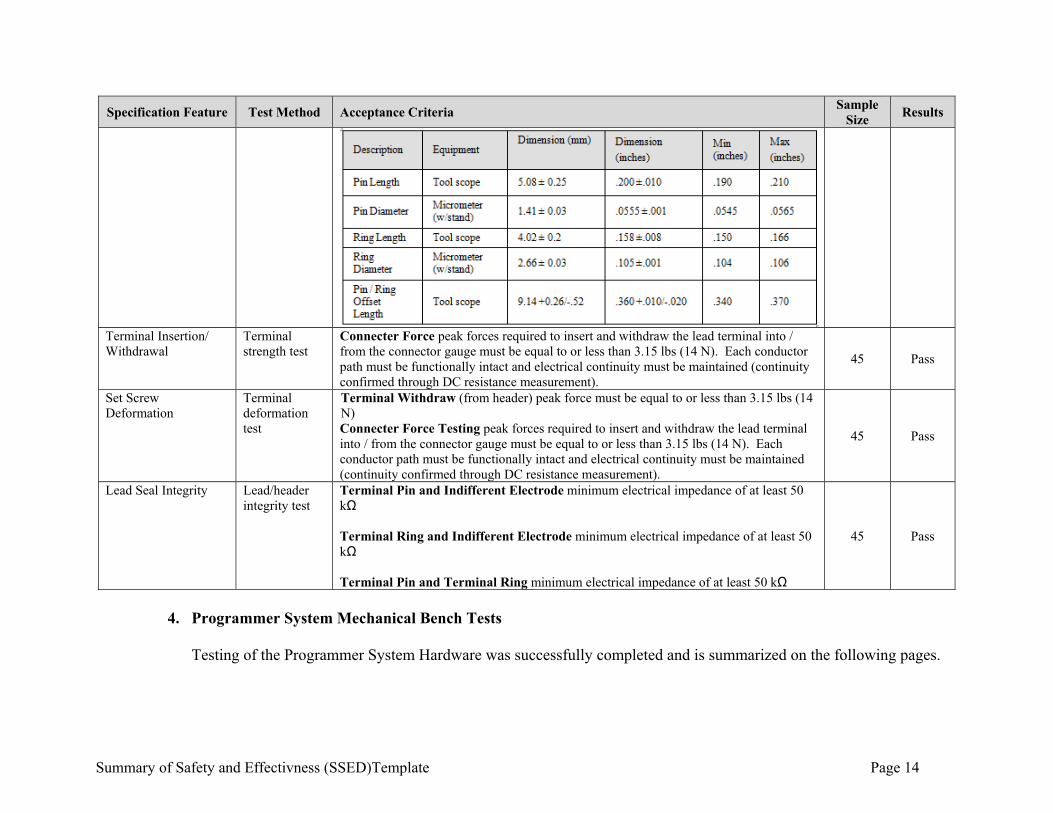
Specification Feature Test Method Acceptance Criteria Sample
Size Results
Terminal Insertion/ Withdrawal
Terminal strength test
Connecter Force peak forces required to insert and withdraw the lead terminal into / from the connector gauge must be equal to or less than 3.15 lbs (14 N). Each conductor path must be functionally intact and electrical continuity must be maintained (continuity confirmed through DC resistance measurement).
45 Pass
Set Screw Deformation
Terminal deformation test
Terminal Withdraw (from header) peak force must be equal to or less than 3.15 lbs (14 N) Connecter Force Testing peak forces required to insert and withdraw the lead terminal into / from the connector gauge must be equal to or less than 3.15 lbs (14 N). Each conductor path must be functionally intact and electrical continuity must be maintained (continuity confirmed through DC resistance measurement).
45 Pass
Lead Seal Integrity Lead/header integrity test
Terminal Pin and Indifferent Electrode minimum electrical impedance of at least 50 kΩ Terminal Ring and Indifferent Electrode minimum electrical impedance of at least 50 kΩ Terminal Pin and Terminal Ring minimum electrical impedance of at least 50 kΩ
45 Pass
4. Programmer System Mechanical Bench Tests
Testing of the Programmer System Hardware was successfully completed and is summarized on the following pages.
Summary of Safety and Effectivness (SSED)Template Page 15
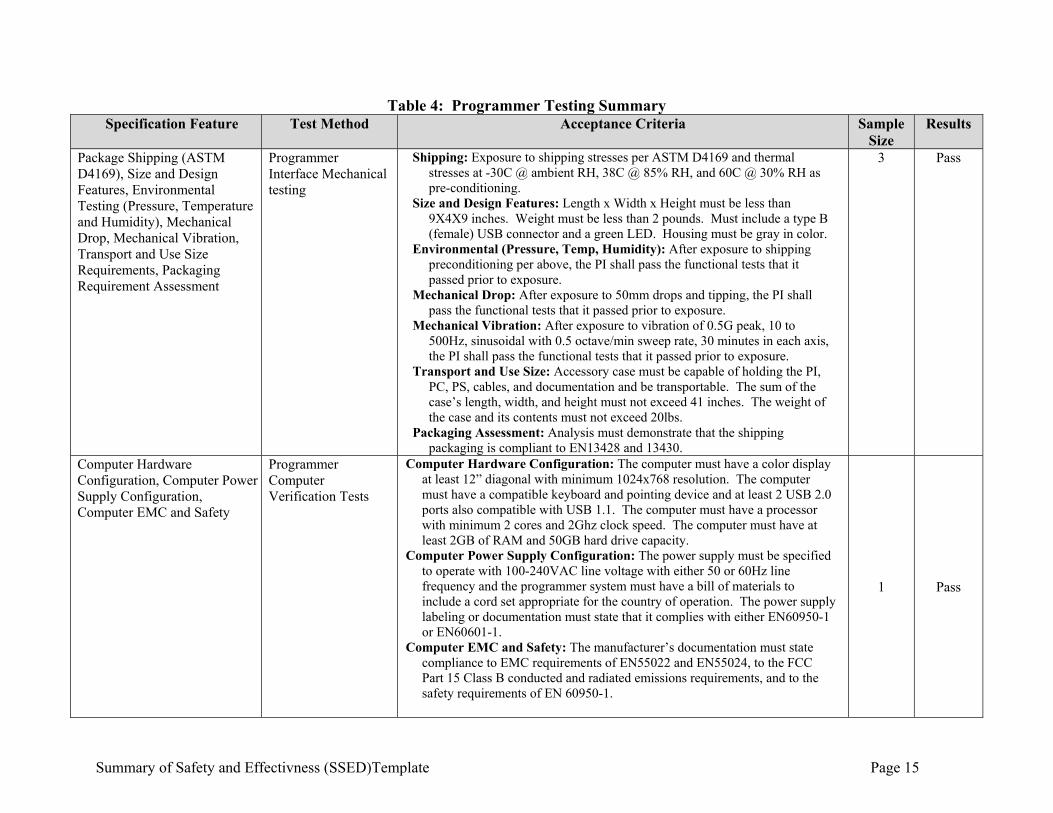
Table 4: Programmer Testing Summary Specification Feature Test Method Acceptance Criteria Sample
Size Results
Package Shipping (ASTM D4169), Size and Design Features, Environmental Testing (Pressure, Temperature and Humidity), Mechanical Drop, Mechanical Vibration, Transport and Use Size Requirements, Packaging Requirement Assessment
Programmer Interface Mechanical testing
Shipping: Exposure to shipping stresses per ASTM D4169 and thermal stresses at -30C @ ambient RH, 38C @ 85% RH, and 60C @ 30% RH as pre-conditioning.
Size and Design Features: Length x Width x Height must be less than 9X4X9 inches. Weight must be less than 2 pounds. Must include a type B (female) USB connector and a green LED. Housing must be gray in color.
Environmental (Pressure, Temp, Humidity): After exposure to shipping preconditioning per above, the PI shall pass the functional tests that it passed prior to exposure.
Mechanical Drop: After exposure to 50mm drops and tipping, the PI shall pass the functional tests that it passed prior to exposure.
Mechanical Vibration: After exposure to vibration of 0.5G peak, 10 to 500Hz, sinusoidal with 0.5 octave/min sweep rate, 30 minutes in each axis, the PI shall pass the functional tests that it passed prior to exposure.
Transport and Use Size: Accessory case must be capable of holding the PI, PC, PS, cables, and documentation and be transportable. The sum of the case’s length, width, and height must not exceed 41 inches. The weight of the case and its contents must not exceed 20lbs.
Packaging Assessment: Analysis must demonstrate that the shipping packaging is compliant to EN13428 and 13430.
3 Pass
Computer Hardware Configuration, Computer Power Supply Configuration, Computer EMC and Safety
Programmer Computer Verification Tests
Computer Hardware Configuration: The computer must have a color display at least 12” diagonal with minimum 1024x768 resolution. The computer must have a compatible keyboard and pointing device and at least 2 USB 2.0 ports also compatible with USB 1.1. The computer must have a processor with minimum 2 cores and 2Ghz clock speed. The computer must have at least 2GB of RAM and 50GB hard drive capacity.
Computer Power Supply Configuration: The power supply must be specified to operate with 100-240VAC line voltage with either 50 or 60Hz line frequency and the programmer system must have a bill of materials to include a cord set appropriate for the country of operation. The power supply labeling or documentation must state that it complies with either EN60950-1 or EN60601-1.
Computer EMC and Safety: The manufacturer’s documentation must state compliance to EMC requirements of EN55022 and EN55024, to the FCC Part 15 Class B conducted and radiated emissions requirements, and to the safety requirements of EN 60950-1.
1 Pass
Summary of Safety and Effectivness (SSED)Template Page 16
Programmer packaging was also tested to representative shipping conditions and according to ASTM D4169. IPG firmware and Programmer software were both developed under a controlled development life cycle model and thoroughly verified and validated for all applicable requirements. Testing was according to risk management process and included code analysis, performance analysis, unit testing, integration testing, and verification testing. System testing was also performed with combined components based on anticipated clinical use scenarios to ensure proper operation as a system.
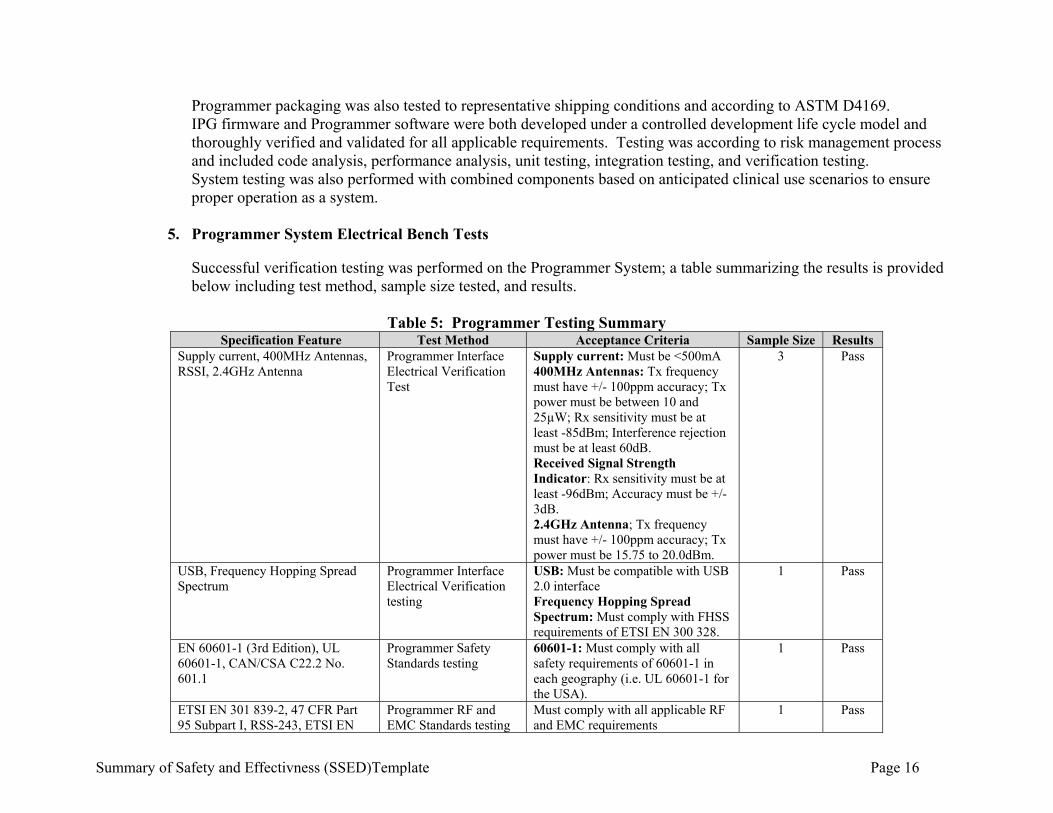
5. Programmer System Electrical Bench Tests
Successful verification testing was performed on the Programmer System; a table summarizing the results is provided below including test method, sample size tested, and results.
Table 5: Programmer Testing Summary Specification Feature Test Method Acceptance Criteria Sample Size Results
Supply current, 400MHz Antennas, RSSI, 2.4GHz Antenna
Programmer Interface Electrical Verification Test
Supply current: Must be <500mA 400MHz Antennas: Tx frequency must have +/- 100ppm accuracy; Tx power must be between 10 and 25µW; Rx sensitivity must be at least -85dBm; Interference rejection must be at least 60dB. Received Signal Strength Indicator: Rx sensitivity must be at least -96dBm; Accuracy must be +/- 3dB. 2.4GHz Antenna; Tx frequency must have +/- 100ppm accuracy; Tx power must be 15.75 to 20.0dBm.
3 Pass
USB, Frequency Hopping Spread Spectrum
Programmer Interface Electrical Verification testing
USB: Must be compatible with USB 2.0 interface Frequency Hopping Spread Spectrum: Must comply with FHSS requirements of ETSI EN 300 328.
1 Pass
EN 60601-1 (3rd Edition), UL 60601-1, CAN/CSA C22.2 No. 601.1
Programmer Safety Standards testing
60601-1: Must comply with all safety requirements of 60601-1 in each geography (i.e. UL 60601-1 for the USA).
1 Pass
ETSI EN 301 839-2, 47 CFR Part 95 Subpart I, RSS-243, ETSI EN
Programmer RF and EMC Standards testing
Must comply with all applicable RF and EMC requirements
1 Pass
Summary of Safety and Effectivness (SSED)Template Page 17
Specification Feature Test Method Acceptance Criteria Sample Size Results 300 328, 47 CFR 15.249, RSS-210, ETSI EN 301 489-1, ETSI EN 301 489-27, ETSI EN 301 489-17, EN 60601-1-2
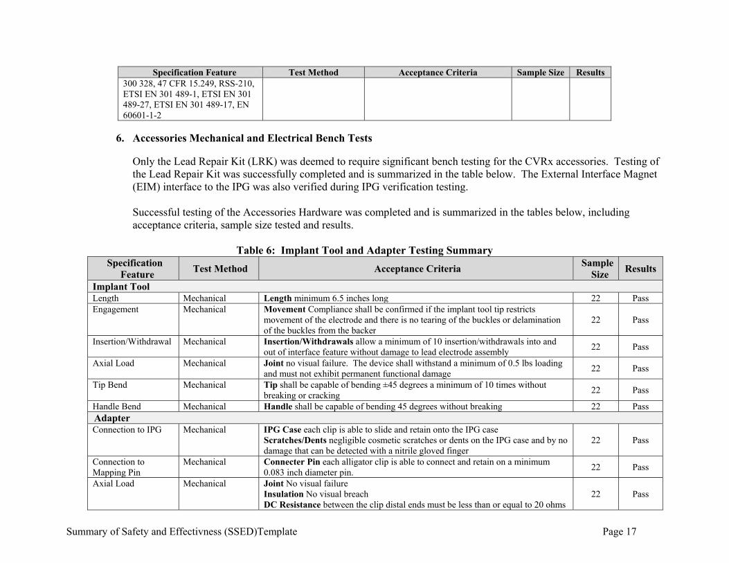
6. Accessories Mechanical and Electrical Bench Tests
Only the Lead Repair Kit (LRK) was deemed to require significant bench testing for the CVRx accessories. Testing of the Lead Repair Kit was successfully completed and is summarized in the table below. The External Interface Magnet (EIM) interface to the IPG was also verified during IPG verification testing. Successful testing of the Accessories Hardware was completed and is summarized in the tables below, including acceptance criteria, sample size tested and results.
Table 6: Implant Tool and Adapter Testing Summary
Specification Feature
Test Method Acceptance Criteria Sample
Size Results
Implant Tool Length Mechanical Length minimum 6.5 inches long 22 Pass Engagement Mechanical Movement Compliance shall be confirmed if the implant tool tip restricts
movement of the electrode and there is no tearing of the buckles or delamination of the buckles from the backer
22 Pass
Insertion/Withdrawal Mechanical Insertion/Withdrawals allow a minimum of 10 insertion/withdrawals into and out of interface feature without damage to lead electrode assembly
22 Pass
Axial Load Mechanical Joint no visual failure. The device shall withstand a minimum of 0.5 lbs loading and must not exhibit permanent functional damage
22 Pass
Tip Bend Mechanical Tip shall be capable of bending ±45 degrees a minimum of 10 times without breaking or cracking
22 Pass
Handle Bend Mechanical Handle shall be capable of bending 45 degrees without breaking 22 Pass Adapter Connection to IPG Mechanical IPG Case each clip is able to slide and retain onto the IPG case
Scratches/Dents negligible cosmetic scratches or dents on the IPG case and by no damage that can be detected with a nitrile gloved finger
22 Pass
Connection to Mapping Pin
Mechanical Connecter Pin each alligator clip is able to connect and retain on a minimum 0.083 inch diameter pin.
22 Pass
Axial Load Mechanical Joint No visual failure Insulation No visual breach DC Resistance between the clip distal ends must be less than or equal to 20 ohms
22 Pass
Summary of Safety and Effectivness (SSED)Template Page 18
Specification Feature
Test Method Acceptance Criteria Sample
Size Results
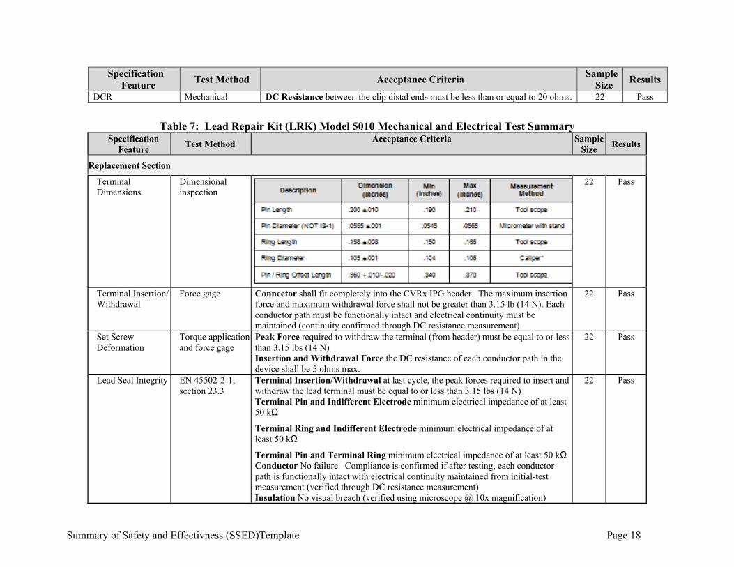
DCR Mechanical DC Resistance between the clip distal ends must be less than or equal to 20 ohms. 22 Pass
Table 7: Lead Repair Kit (LRK) Model 5010 Mechanical and Electrical Test Summary
Specification Feature
Test Method Acceptance Criteria Sample
Size Results
Replacement Section
Terminal Dimensions
Dimensional inspection
22 Pass
Terminal Insertion/ Withdrawal
Force gage Connector shall fit completely into the CVRx IPG header. The maximum insertion force and maximum withdrawal force shall not be greater than 3.15 lb (14 N). Each conductor path must be functionally intact and electrical continuity must be maintained (continuity confirmed through DC resistance measurement)
22 Pass
Set Screw Deformation
Torque application and force gage
Peak Force required to withdraw the terminal (from header) must be equal to or less than 3.15 lbs (14 N) Insertion and Withdrawal Force the DC resistance of each conductor path in the device shall be 5 ohms max.
22 Pass
Lead Seal Integrity EN 45502-2-1, section 23.3
Terminal Insertion/Withdrawal at last cycle, the peak forces required to insert and withdraw the lead terminal must be equal to or less than 3.15 lbs (14 N) Terminal Pin and Indifferent Electrode minimum electrical impedance of at least 50 kΩ
Terminal Ring and Indifferent Electrode minimum electrical impedance of at least 50 kΩ
Terminal Pin and Terminal Ring minimum electrical impedance of at least 50 kΩ Conductor No failure. Compliance is confirmed if after testing, each conductor path is functionally intact with electrical continuity maintained from initial-test measurement (verified through DC resistance measurement) Insulation No visual breach (verified using microscope @ 10x magnification)
22 Pass
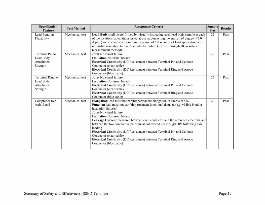
Summary of Safety and Effectivness (SSED)Template Page 19
Specification Feature
Test Method Acceptance Criteria Sample
Size Results
Lead Bending Flexibility
Mechanical test Lead Body shall be confirmed by visually inspecting each lead body sample at each of the locations/orientations listed above as contacting the entire 180 degree (±5.0 degree) rod surface after a minimum period of 5.0 seconds of load application with no visible insulation failure or conductor failure (verified through DC resistance measurement method)
22 Pass
Terminal Pin to Lead Body Attachment Strength
Mechanical test Joint No visual failure Insulation No visual breach Electrical Continuity (DC Resistance) between Terminal Pin and Cathode Conductor (clear cable) Electrical Continuity (DC Resistance) between Terminal Ring and Anode Conductor (blue cable)
22 Pass
Terminal Ring to Lead Body Attachment Strength
Mechanical test Joint No visual failure Insulation No visual breach Electrical Continuity (DC Resistance) between Terminal Pin and Cathode Conductor (clear cable) Electrical Continuity (DC Resistance) between Terminal Ring and Anode Conductor (blue cable)
22 Pass
Comprehensive Axial Load
Mechanical test Elongation lead must not exhibit permanent elongation in excess of 5% Function lead must not exhibit permanent functional damage (e.g. visible bond or insulation failures) Joint No visual failure Insulation No visual breach Leakage Current measured between each conductor and the reference electrode and between the two conductive paths must not exceed 2.0 mA @100V following axial loading Electrical Continuity (DC Resistance) between Terminal Pin and Cathode Conductor (clear cable) Electrical Continuity (DC Resistance) between Terminal Ring and Anode Conductor (blue cable)
22 Pass

Summary of Safety and Effectivness (SSED)Template Page 20
Specification Feature
Test Method Acceptance Criteria Sample
Size Results
Terminal Durability
Mechanical test Terminal Insertion/Withdrawal at last cycle, the peak forces required to insert and withdraw the lead terminal must be equal to or less than 3.15 lbs (14 N) Terminal Pin and Indifferent Electrode minimum electrical impedance of at least 50 kΩ Terminal Ring and Indifferent Electrode minimum electrical impedance of at least 50 kΩ Terminal Pin and Terminal Ring minimum electrical impedance of at least 50 kΩ Conductor No failure. Compliance is confirmed if after testing, each conductor path is functionally intact with electrical continuity maintained from initial-test measurement (verified through DC resistance measurement) Insulation No visual breach (verified using microscope @ 10x magnification)
22 Pass
Lead Body Flex Test
Mechanical test Conductor All devices must meet the lead body flex testing with no conductor failure. Compliance is confirmed if after 94,000 cycles in each orientation, each conductor path is functionally intact with electrical continuity maintained from pre-flex measurement (verified through DC resistance measurement method of section 5.1).
22 Pass
Terminal Connection Flex Endurance
Mechanical test Lead Terminal Connector flex testing with no conductor failures. Compliance is confirmed if after 164,000 cycles in each orientation, each conductor path is functionally intact with electrical continuity maintained (verified through DC resistance measurement)
22 Pass
DC Resistance Electromechanical test
Conductor Path DC resistance in the device shall be 5 ohms max 22 Pass
Insulation Integrity Electromechanical test
Leakage Current measured between each conductor and the reference electrode, and between any two conductors, may not exceed 2.0 mA during the voltage application
22 Pass
System Requirements
Lead Body Bending Flexibility
Mechanical test Lead Body sample must touch the rod at the edges of the rod surface at 90° ± 5° and 270° ± 5° after a period of 5 seconds of load application as demonstrated through visual inspection
22 Pass
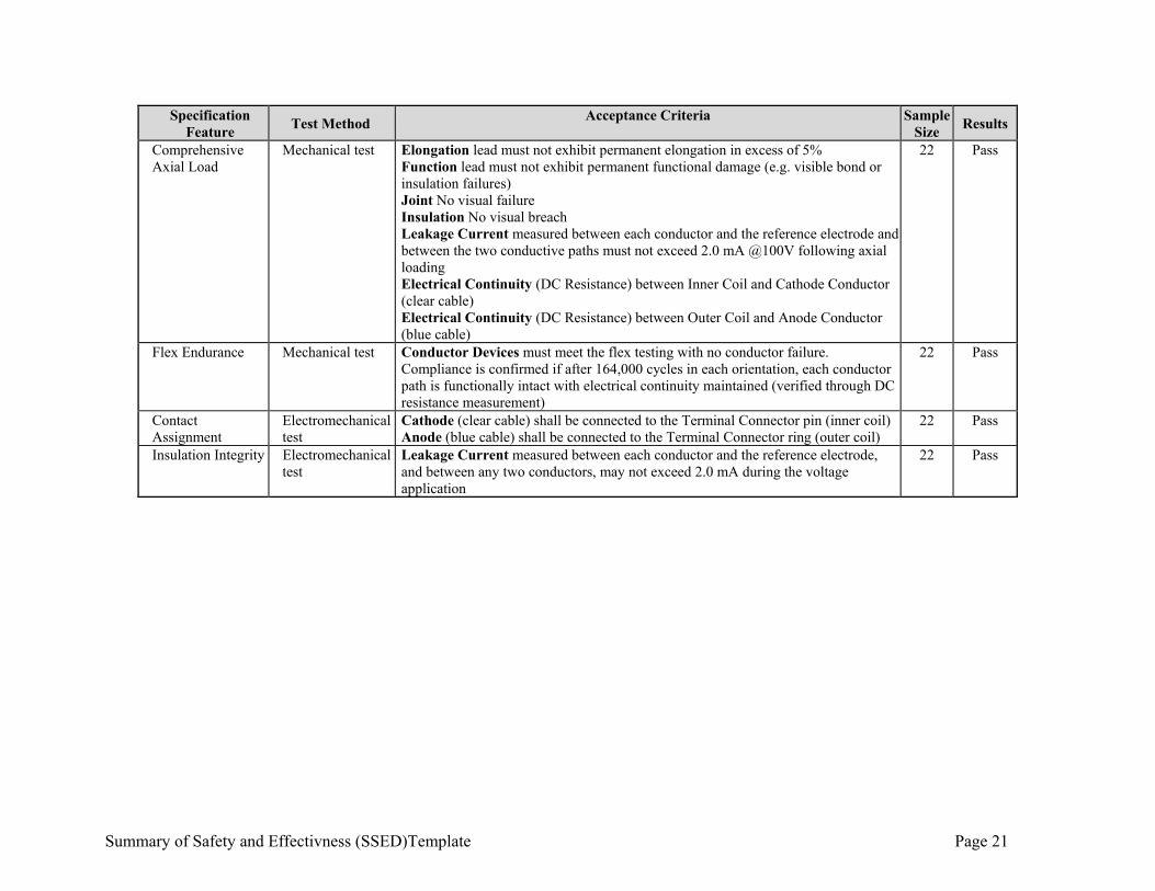
Summary of Safety and Effectivness (SSED)Template Page 21
Specification Feature
Test Method Acceptance Criteria Sample
Size Results
Comprehensive Axial Load
Mechanical test Elongation lead must not exhibit permanent elongation in excess of 5% Function lead must not exhibit permanent functional damage (e.g. visible bond or insulation failures) Joint No visual failure Insulation No visual breach Leakage Current measured between each conductor and the reference electrode and between the two conductive paths must not exceed 2.0 mA @100V following axial loading Electrical Continuity (DC Resistance) between Inner Coil and Cathode Conductor (clear cable) Electrical Continuity (DC Resistance) between Outer Coil and Anode Conductor (blue cable)
22 Pass
Flex Endurance Mechanical test Conductor Devices must meet the flex testing with no conductor failure. Compliance is confirmed if after 164,000 cycles in each orientation, each conductor path is functionally intact with electrical continuity maintained (verified through DC resistance measurement)
22 Pass
Contact Assignment
Electromechanical test
Cathode (clear cable) shall be connected to the Terminal Connector pin (inner coil) Anode (blue cable) shall be connected to the Terminal Connector ring (outer coil)
22
Pass
Insulation Integrity Electromechanical test
Leakage Current measured between each conductor and the reference electrode, and between any two conductors, may not exceed 2.0 mA during the voltage application
22 Pass
PMA P180050: FDA Summary of Safety and Effectiveness Data Page 22
7. Software and Firmware Testing
The CVRx Development Life Cycle Model has three phases: Firmware/Software Planning, Firmware/Software Development and Firmware/Software Maintenance. This type of life cycle reflects an iterative process of development in which the firmware/software is planned, assessed, defined, designed, tested, implemented, and controlled. A firmware/software project repeatedly passes through these phases in iterations. The baseline starts in the Firmware/Software Planning Phase. Each subsequent iteration builds on the baseline. All planning and initial risk analysis activities are performed during the Firmware/Software Planning Phase. The software and firmware verification and validation testing was successfully completed.
a) IPG Firmware
The Firmware for the IPG is verified and validated through testing and documentation of the results. The results of the testing were successful and the analysis found the firmware to be adequate.
b) Programmer Interface (PI) Firmware
The PI Firmware is verified and validated through code analysis, performance analysis, unit testing, integration testing, and verification testing. The results of the testing were successful and the analysis found the firmware to be adequate.
c) Programmer Software
The Programmer Software is verified and validated through code analysis, unit testing, integration testing, and verification testing. The results of the testing were successful and the analysis found the software to be adequate.
d) Cybersecurity
The cybersecurity of the BAROSTIM NEO System has been assessed in a security hazard analysis, including automated and manual testing to assess the system against common vulnerabilities and attacks. Cybersecurity risks and mitigations are documented in the risk management system. The residual cybersecurity risk associated with the BAROSTIM NEO System is currently acceptable.
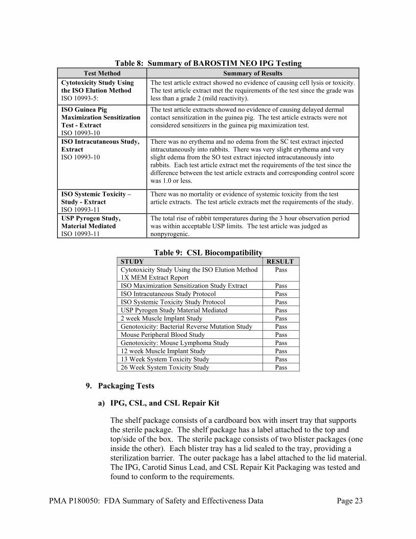
8. Biocompatibility Studies
All testing on the BAROSTIM NEO System was performed in accordance to the ISO 10991 Standard. The IPG was tested for cytotoxicity, maximization sensitization, intracutaneous extract, systemic toxicity extract, and material mediated pyrogens and all tests passed meeting their acceptance criteria.
PMA P180050: FDA Summary of Safety and Effectiveness Data Page 23
Table 8: Summary of BAROSTIM NEO IPG Testing
Test Method Summary of Results Cytotoxicity Study Using the ISO Elution Method ISO 10993-5:
The test article extract showed no evidence of causing cell lysis or toxicity. The test article extract met the requirements of the test since the grade was less than a grade 2 (mild reactivity).
ISO Guinea Pig Maximization Sensitization Test - Extract ISO 10993-10
The test article extracts showed no evidence of causing delayed dermal contact sensitization in the guinea pig. The test article extracts were not considered sensitizers in the guinea pig maximization test.
ISO Intracutaneous Study, Extract ISO 10993-10
There was no erythema and no edema from the SC test extract injected intracutaneously into rabbits. There was very slight erythema and very slight edema from the SO test extract injected intracutaneously into rabbits. Each test article extract met the requirements of the test since the difference between the test article extracts and corresponding control score was 1.0 or less.
ISO Systemic Toxicity – Study - Extract ISO 10993-11
There was no mortality or evidence of systemic toxicity from the test article extracts. The test article extracts met the requirements of the study.
USP Pyrogen Study, Material Mediated ISO 10993-11
The total rise of rabbit temperatures during the 3 hour observation period was within acceptable USP limits. The test article was judged as nonpyrogenic.
Table 9: CSL Biocompatibility
STUDY RESULT Cytotoxicity Study Using the ISO Elution Method 1X MEM Extract Report
Pass
ISO Maximization Sensitization Study Extract Pass ISO Intracutaneous Study Protocol Pass ISO Systemic Toxicity Study Protocol Pass USP Pyrogen Study Material Mediated Pass 2 week Muscle Implant Study Pass Genotoxicity: Bacterial Reverse Mutation Study Pass Mouse Peripheral Blood Study Pass Genotoxicity: Mouse Lymphoma Study Pass 12 week Muscle Implant Study Pass 13 Week System Toxicity Study Pass 26 Week System Toxicity Study Pass
9. Packaging Tests
a) IPG, CSL, and CSL Repair Kit
The shelf package consists of a cardboard box with insert tray that supports the sterile package. The shelf package has a label attached to the top and top/side of the box. The sterile package consists of two blister packages (one inside the other). Each blister tray has a lid sealed to the tray, providing a sterilization barrier. The outer package has a label attached to the lid material. The IPG, Carotid Sinus Lead, and CSL Repair Kit Packaging was tested and found to conform to the requirements.
PMA P180050: FDA Summary of Safety and Effectiveness Data Page 24
b) Programmer System
The Programmer System, consisting of the assembled Programmer Interface and PI-PC USB Cable, is placed in the Computer Case Sub-assembly. The computer is placed back in the original manufacturer’s box and placed beside the computer case subassembly. Those two are wrapped in disposable cushioning (bubble wrap or equivalent) inside a box for shipping. A shipping label is placed on the shipping box and the box is sealed. The Programmer System Packaging was tested and found to conform to the requirements.
c) Ship Testing
The packaged components of the BAROSTIM NEO System are tested against industry standards to ensure that they remain functional after the shipping process.
10. Shelf Life
a) IPG
The BAROSTIM NEO device and package were subjected to Design Validation Test (DVT) for a one year accelerated shelf life performance. The BAROSTIM NEO IPG and package also completed a real-time shelf life performance DVT. This testing of real-time aged packages for over 2 years at ambient conditions within CVRx and completed preconditioning and performance testing. All test samples passed the testing. The IPG is labeled for two-year shelf life.
b) CSL
The CSL was fully DVT-qualified for a three-year accelerated shelf life performance. CSL real time aging is in progress. The CSL is labeled for two-year shelf life.
c) CSL Repair Kit
The LRK was fully DVT-qualified for a two-year accelerated shelf life performance. The CSL Repair Kit is labeled for two-year shelf life.
B. Animal Studies
CVRx has performed research and Good Laboratory Practice (GLP) safety evaluations of BAROSTIM THERAPY using BAROSTIM NEO System, in an ovine model. The system was tested both acutely and chronically (180 days) in the ovine model consisting of 12 test articles and three ovine animals with therapy ON and OFF. The 180-day study was completed with favorable conclusions for Baroreflex Activation Therapy®
PMA P180050: FDA Summary of Safety and Effectiveness Data Page 25
with the BAROSTIM NEO System regarding gross and histological tissue response and device integrity. No article related gross issues, histological issues, or adverse events were found in the 180-day study. No significant issues were determined when comparing the therapy ON versus therapy OFF groups. The lack of adverse histological findings with and without electrical stimulation supported the safety of the BAROSTIM NEO System for use in clinical testing.
X. SUMMARY OF PRIMARY CLINICAL STUDIES
The applicant performed a clinical study to establish a reasonable assurance of safety and effectiveness of the BAROSTIM NEO System for the reduction of the symptoms of heart failure in the US under IDE G120010. The BAROSTIM NEO® - Baroreflex Activation Therapy® for Heart Failure (BeAT-HF) trial data is the basis for the PMA approval decision. A summary of the BeAT-HF Pivotal Trial is presented below. A. Study Design
Subjects were treated between April 5, 2016 and April 22, 2019. The locked database for this PMA, reflected data collected through April 22, 2019 and included 408 randomized subjects. There were 92 investigational sites from both the United States (US, 91) and United Kingdom (UK, 1). The study was a prospective, multi-center, two-arm, randomized trial in subjects with reduced ejection fraction heart failure. Subjects were randomized in a 1:1 ratio to receive BAROSTIM THERAPY with an implanted BAROSTIM NEO System in addition to medical management (BAT + MM) or to receive medical management (MM) alone (no device implant). A key enrollment criteria includes post-consent screening measurements that was obtained only after the subject completed a medication optimization and 4-week medication stabilization period. For all subjects, the heart failure medication regimen must remain stable during the 4-week medication stabilization period, except for minor adjustments. The control group (MM arm) subjects were treated identically with regard to all screening and follow-up testing at the same time periods as the device group at screening, baseline and all follow-ups. Prior to randomization, site personnel were required to provide an anticipated implant date. For subjects randomized to the Medical Management Arm, this date was used for the timing of all other trial visits. For subjects randomized to the Device Arm, trial visits were based on the actual date of device implant. The trial was designed in two phases, Expedited and Extended. The subjects of primary interest for this PMA are the Expedited Phase population. The Expedited Phase population for the analysis of the 6-month endpoints includes all subjects randomized to fulfill the individual sample size requirements for those endpoints (MLWHF QOL, 6MHW, NT-proBNP in both arms of the trial and Major Adverse Neurological & Cardiac Events (MANCE) free rate in the BAT + MM arm only).
PMA P180050: FDA Summary of Safety and Effectiveness Data Page 26
The Extended Phase is designed to collect post-market long-term follow-up data, resulting in assessment of Morbidity and Mortality (M&M) data and a later PMA Supplement application. The trial oversight used a blinded to arm assignment, core laboratory to analyze and document the NT-proBNP testing. In addition, all heart failure hospitalization and censored events were blindly adjudicated by independent evaluators on the Clinical Events Committee (CEC) and the trial was also overseen by an independent Data Monitoring Committee (DMC) and Adverse Events Committee (AEC). Lastly, an Executive Steering committee (ESC), consisting of independent physicians assisted the sponsor in the development and execution of the trial. 1. Clinical Inclusion and Exclusion Criteria
Enrollment in the BeAT-HF study was limited to subjects who met the following inclusion criteria: 1) Age 21 years or above. 2) Currently NYHA Class II or III heart failure. For NYHA Class II, must have
been NYHA Class III at any point in time within 3 calendar months prior to enrollment or at time of screening (enrollment is defined as the date the subject provided written consent).
3) Left ventricular ejection fraction ≤ 35% within 45 days prior to randomization.
4) Heart failure accompanied by BNP ≥ 100 or NT-proBNP ≥ 400 within 45 days prior to randomization, or a heart failure hospitalization in the past 12 months. Note: Heart failure hospitalization may include an overnight hospital or hospital-based observation unit stay with a primary diagnosis of heart failure or an emergency room visit with a primary diagnosis of heart failure. Note: Screening BNP/NT-proBNP must be measured in an outpatient setting at a time when the subject is thought to be clinically stable. Note: If subject is taking sacubitril/valsartan (i.e. Entresto), NT-proBNP must be used for screening eligibility.
5) On optimal, stable, Guideline Directed Medical Therapy (GDMT) per country specific guidelines for the treatment of heart-failure throughout screening/baseline evaluation and for at least 4 weeks prior to obtaining any post-consent screening parameters:
No more than a 100% increase or a 50% decrease of the dosage of any one medication other than a diuretic.
Medication changes within a drug class are allowed as long as the equivalent dosage is within the limits specified above.
Unrestricted changes in diuretics are allowed as long as the subject remains on a diuretic.
6) Six-minute hall walk (6MHW) ≥ 150 m AND ≤ 400 m within 45 days prior to randomization.
PMA P180050: FDA Summary of Safety and Effectiveness Data Page 27
7) The artery planned for the BAROSTIM NEO implant must meet both of the following criteria:
At least one carotid bifurcation as identification by a bilateral carotid duplex ultrasound within 6 months prior to randomization that is:
a. Below the level of the mandible AND b. No ulcerative carotid arterial plaques AND c. No carotid atherosclerosis producing a 50% or greater
reduction in linear diameter in the internal carotid AND d. No carotid atherosclerosis producing a 50% or greater
reduction in linear diameter in the distal common carotid No prior surgery, radiation, or endovascular stent placement in the
carotid artery or the carotid sinus region. 8) If female and of childbearing potential, must use a medically accepted method
of birth control (e.g., barrier method with spermicide, oral contraceptive, or abstinence) and agree to continue use of this method for the duration of the trial. Women of childbearing potential must have a negative pregnancy test within 14 days prior to randomization.
9) Received a standard cardiac work up and is an appropriate candidate for the study and the surgical procedure as determined by a trial cardiologist and a trial surgeon.
10) Subjects implanted with a cardiac rhythm management device that does not utilize an intracardiac lead, or implanted with a neurostimulation device, must be approved by the CVRx Clinical department.
11) Signed a CVRx-approved informed consent form for participation in this trial.
Subjects were not permitted to enroll in the BeAT-HF study if they met any of the following exclusion criteria: 1) Received cardiac resynchronization therapy (CRT) within six months of
randomization, or is actively receiving CRT. 2) Currently have a Class I indication for a cardiac resynchronization therapy
(CRT) device according to AHA/ACC/ESC guidelines for the treatment of congestive heart failure.i,ii
3) Known or suspected baroreflex failure or autonomic neuropathy. 4) AHA/ACC Stage D heart failure within 45 days prior to randomization. 5) Body mass index > 40. 6) Serum estimated glomerular filtration rate (eGFR) < 25 ml/min/1.73 m2
within 45 days prior to randomization. 7) Recurring resting heart rate of either < 60 bpm or > 100 bpm via clinic
measurements within 45 days prior to randomization. (Note: Heart rate < 60 bpm is not applicable to subjects with an implanted device capable of pacing.)
8) Recurring symptomatic hypotension within 45 days prior to randomization. 9) Significant uncontrolled symptomatic bradyarrhythmias or unstable
ventricular arrhythmias.
PMA P180050: FDA Summary of Safety and Effectiveness Data Page 28
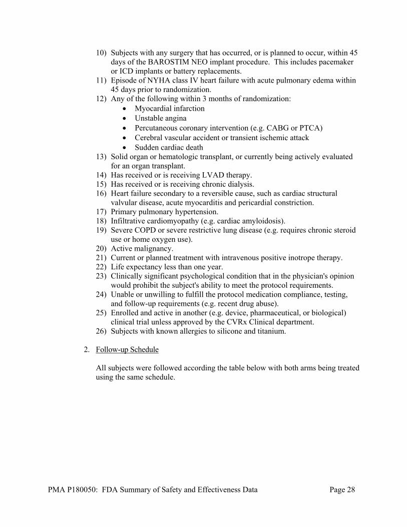
10) Subjects with any surgery that has occurred, or is planned to occur, within 45 days of the BAROSTIM NEO implant procedure. This includes pacemaker or ICD implants or battery replacements.
11) Episode of NYHA class IV heart failure with acute pulmonary edema within 45 days prior to randomization.
12) Any of the following within 3 months of randomization: Myocardial infarction Unstable angina Percutaneous coronary intervention (e.g. CABG or PTCA) Cerebral vascular accident or transient ischemic attack Sudden cardiac death
13) Solid organ or hematologic transplant, or currently being actively evaluated for an organ transplant.
14) Has received or is receiving LVAD therapy. 15) Has received or is receiving chronic dialysis. 16) Heart failure secondary to a reversible cause, such as cardiac structural
valvular disease, acute myocarditis and pericardial constriction. 17) Primary pulmonary hypertension. 18) Infiltrative cardiomyopathy (e.g. cardiac amyloidosis). 19) Severe COPD or severe restrictive lung disease (e.g. requires chronic steroid
use or home oxygen use). 20) Active malignancy. 21) Current or planned treatment with intravenous positive inotrope therapy. 22) Life expectancy less than one year. 23) Clinically significant psychological condition that in the physician's opinion
would prohibit the subject's ability to meet the protocol requirements. 24) Unable or unwilling to fulfill the protocol medication compliance, testing,
and follow-up requirements (e.g. recent drug abuse). 25) Enrolled and active in another (e.g. device, pharmaceutical, or biological)
clinical trial unless approved by the CVRx Clinical department. 26) Subjects with known allergies to silicone and titanium.
2. Follow-up Schedule
All subjects were followed according the table below with both arms being treated using the same schedule.
PMA P180050: FDA Summary of Safety and Effectiveness Data Page 29
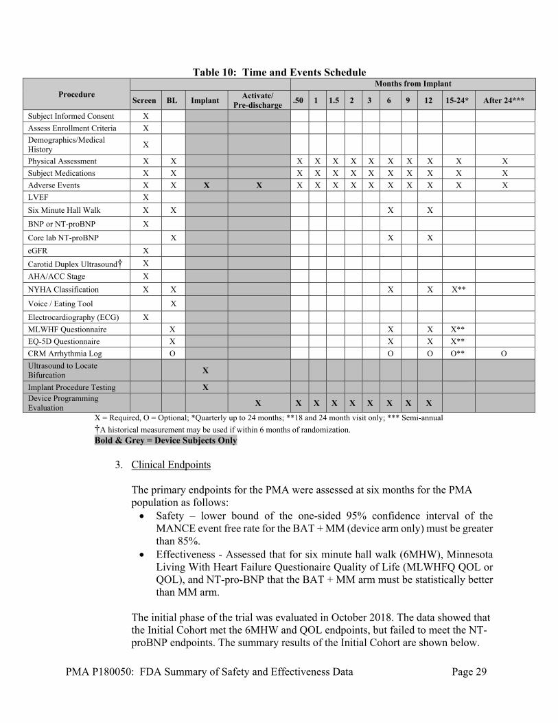
Table 10: Time and Events Schedule
Procedure Months from Implant
Screen BL Implant Activate/
Pre-discharge .50 1 1.5 2 3 6 9 12 15-24* After 24***
Subject Informed Consent X
Assess Enrollment Criteria X
Demographics/Medical History
X
Physical Assessment X X X X X X X X X X X X
Subject Medications X X X X X X X X X X X X
Adverse Events X X X X X X X X X X X X X X
LVEF X
Six Minute Hall Walk X X X X
BNP or NT-proBNP X
Core lab NT-proBNP X X X
eGFR X
Carotid Duplex Ultrasound† X
AHA/ACC Stage X
NYHA Classification X X X X X**
Voice / Eating Tool X
Electrocardiography (ECG) X
MLWHF Questionnaire X X X X**
EQ-5D Questionnaire X X X X**
CRM Arrhythmia Log O O O O** O
Ultrasound to Locate Bifurcation
X
Implant Procedure Testing X Device Programming Evaluation
X X X X X X X X X
X = Required, O = Optional; *Quarterly up to 24 months; **18 and 24 month visit only; *** Semi-annual
†A historical measurement may be used if within 6 months of randomization. Bold & Grey = Device Subjects Only
3. Clinical Endpoints
The primary endpoints for the PMA were assessed at six months for the PMA population as follows: Safety – lower bound of the one-sided 95% confidence interval of the
MANCE event free rate for the BAT + MM (device arm only) must be greater than 85%.
Effectiveness - Assessed that for six minute hall walk (6MHW), Minnesota Living With Heart Failure Questionaire Quality of Life (MLWHFQ QOL or QOL), and NT-pro-BNP that the BAT + MM arm must be statistically better than MM arm.
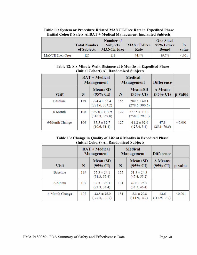
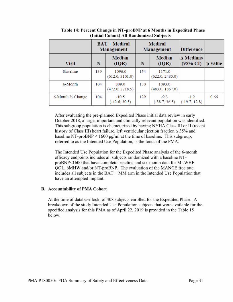
The initial phase of the trial was evaluated in October 2018. The data showed that the Initial Cohort met the 6MHW and QOL endpoints, but failed to meet the NT-proBNP endpoints. The summary results of the Initial Cohort are shown below.
PMA P180050: FDA Summary of Safety and Effectiveness Data Page 30
Table 11: System or Procedure Related MANCE-Free Rate in Expedited Phase
(Initial Cohort) Safety AllBAT + Medical Management Implanted Subjects
Table 12: Six Minute Walk Distance at 6 Months in Expedited Phase (Initial Cohort) All Randomized Subjects
Table 13: Change in Quality of Life at 6 Months in Expedited Phase (Initial Cohort) All Randomized Subjects
PMA P180050: FDA Summary of Safety and Effectiveness Data Page 31
Table 14: Percent Change in NT-proBNP at 6 Months in Expedited Phase (Initial Cohort) All Randomized Subjects
After evaluating the pre-planned Expedited Phase initial data review in early October 2018, a large, important and clinically relevant population was identified. This subgroup population is characterized by having NYHA Class III or II (recent history of Class III) heart failure, left ventricular ejection fraction ≤ 35% and baseline NT-proBNP < 1600 pg/ml at the time of baseline. This subgroup, referred to as the Intended Use Population, is the focus of the PMA. The Intended Use Population for the Expedited Phase analysis of the 6-month efficacy endpoints includes all subjects randomized with a baseline NT-proBNP<1600 that have complete baseline and six-month data for MLWHF QOL, 6MHW and/or NT-proBNP. The evaluation of the MANCE free rate includes all subjects in the BAT + MM arm in the Intended Use Population that have an attempted implant.
B. Accountability of PMA Cohort
At the time of database lock, of 408 subjects enrolled for the Expedited Phase. A breakdown of the study Intended Use Population subjects that were available for the specified analysis for this PMA as of April 22, 2019 is provided in the Table 15 below.

PMA P180050: FDA Summary of Safety and Effectiveness Data Page 32
Table 15: Analysis Populations for the Expedited Phase - Intended Use
Description
BAT + Medical
Management Medical
Management Total Expedited Phase Population - Intended Use 130 134 264 Expedited Phase Six Month Efficacy Analysis Population - Intended Use
120 125 245
Not in Expedited Phase Six Month Efficacy Analysis Population - Intended Use
10 9 19
No Implant Attempt 5 N/A 5 Died / LVAD / Heart Transplant prior to 6 month visit 1 5 6 Withdrew / LTFU prior to 6 month visit 2 0 2 Missed 6 month visit 2 4 6 Expedited Phase Safety Analysis Population - Intended Use 125 N/A 125 Not in Expedited Phase Safety Analysis Population - Intended Use
5 N/A 5
No Implant Attempt 5 N/A 5 Total Randomized - Intended Use 130 134 264
Within the population supporting the Expedited Phase, there are two cohorts of data. Data that was previously analyzed in the original PMA dated December 14, 2018, called the Initial Cohort data (summarized above), and data that had not been previously unblinded and analyzed and is also included here, called the Second Cohort data that was collected through April 22, 2019.
C. Study Population Demographics and Baseline Parameters
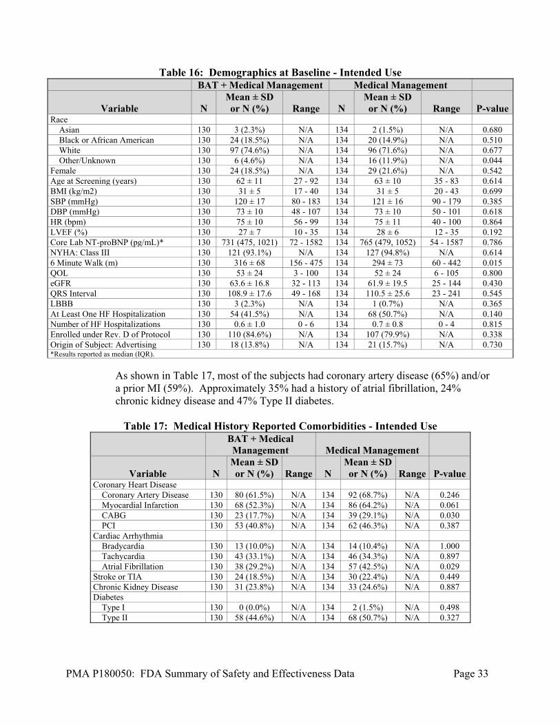
The demographics of the study Intended Use Population are typical for a reduced ejection fraction heart failure study performed in the US and UK. Baseline demographics for Expedited Phase Intended Use Population subjects are in Table 16 below. Demographics between the two randomized arms were balanced. Approximately 35% had a history of atrial fibrillation, 24% chronic kidney disease and 47% Type II diabetes. Almost all subjects (93 to 95%) are NYHA Class III at baseline with an average LVEF of 27% for BAT +MM and 28% for MM.
PMA P180050: FDA Summary of Safety and Effectiveness Data Page 33
Table 16: Demographics at Baseline - Intended Use BAT + Medical Management Medical Management
Variable N Mean ± SD or N (%) Range N
Mean ± SD or N (%) Range P-value
Race Asian 130 3 (2.3%) N/A 134 2 (1.5%) N/A 0.680 Black or African American 130 24 (18.5%) N/A 134 20 (14.9%) N/A 0.510 White 130 97 (74.6%) N/A 134 96 (71.6%) N/A 0.677 Other/Unknown 130 6 (4.6%) N/A 134 16 (11.9%) N/A 0.044 Female 130 24 (18.5%) N/A 134 29 (21.6%) N/A 0.542 Age at Screening (years) 130 62 ± 11 27 - 92 134 63 ± 10 35 - 83 0.614 BMI (kg/m2) 130 31 ± 5 17 - 40 134 31 ± 5 20 - 43 0.699 SBP (mmHg) 130 120 ± 17 80 - 183 134 121 ± 16 90 - 179 0.385 DBP (mmHg) 130 73 ± 10 48 - 107 134 73 ± 10 50 - 101 0.618 HR (bpm) 130 75 ± 10 56 - 99 134 75 ± 11 40 - 100 0.864 LVEF (%) 130 27 ± 7 10 - 35 134 28 ± 6 12 - 35 0.192 Core Lab NT-proBNP (pg/mL)* 130 731 (475, 1021) 72 - 1582 134 765 (479, 1052) 54 - 1587 0.786 NYHA: Class III 130 121 (93.1%) N/A 134 127 (94.8%) N/A 0.614 6 Minute Walk (m) 130 316 ± 68 156 - 475 134 294 ± 73 60 - 442 0.015 QOL 130 53 ± 24 3 - 100 134 52 ± 24 6 - 105 0.800 eGFR 130 63.6 ± 16.8 32 - 113 134 61.9 ± 19.5 25 - 144 0.430 QRS Interval 130 108.9 ± 17.6 49 - 168 134 110.5 ± 25.6 23 - 241 0.545 LBBB 130 3 (2.3%) N/A 134 1 (0.7%) N/A 0.365 At Least One HF Hospitalization 130 54 (41.5%) N/A 134 68 (50.7%) N/A 0.140 Number of HF Hospitalizations 130 0.6 ± 1.0 0 - 6 134 0.7 ± 0.8 0 - 4 0.815 Enrolled under Rev. D of Protocol 130 110 (84.6%) N/A 134 107 (79.9%) N/A 0.338 Origin of Subject: Advertising 130 18 (13.8%) N/A 134 21 (15.7%) N/A 0.730 *Results reported as median (IQR).
As shown in Table 17, most of the subjects had coronary artery disease (65%) and/or a prior MI (59%). Approximately 35% had a history of atrial fibrillation, 24% chronic kidney disease and 47% Type II diabetes.
Table 17: Medical History Reported Comorbidities - Intended Use
BAT + Medical Management Medical Management
Variable N Mean ± SD or N (%) Range N
Mean ± SD or N (%) Range P-value
Coronary Heart Disease Coronary Artery Disease 130 80 (61.5%) N/A 134 92 (68.7%) N/A 0.246 Myocardial Infarction 130 68 (52.3%) N/A 134 86 (64.2%) N/A 0.061 CABG 130 23 (17.7%) N/A 134 39 (29.1%) N/A 0.030 PCI 130 53 (40.8%) N/A 134 62 (46.3%) N/A 0.387 Cardiac Arrhythmia Bradycardia 130 13 (10.0%) N/A 134 14 (10.4%) N/A 1.000 Tachycardia 130 43 (33.1%) N/A 134 46 (34.3%) N/A 0.897 Atrial Fibrillation 130 38 (29.2%) N/A 134 57 (42.5%) N/A 0.029 Stroke or TIA 130 24 (18.5%) N/A 134 30 (22.4%) N/A 0.449 Chronic Kidney Disease 130 31 (23.8%) N/A 134 33 (24.6%) N/A 0.887 Diabetes Type I 130 0 (0.0%) N/A 134 2 (1.5%) N/A 0.498 Type II 130 58 (44.6%) N/A 134 68 (50.7%) N/A 0.327
PMA P180050: FDA Summary of Safety and Effectiveness Data Page 34
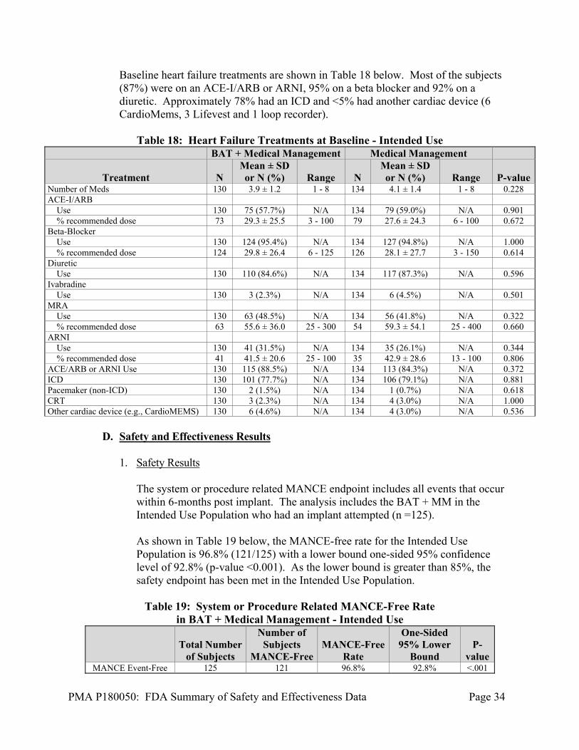
Baseline heart failure treatments are shown in Table 18 below. Most of the subjects (87%) were on an ACE-I/ARB or ARNI, 95% on a beta blocker and 92% on a diuretic. Approximately 78% had an ICD and <5% had another cardiac device (6 CardioMems, 3 Lifevest and 1 loop recorder).
Table 18: Heart Failure Treatments at Baseline - Intended Use
BAT + Medical Management Medical Management
Treatment N Mean ± SD or N (%) Range N
Mean ± SD or N (%) Range P-value
Number of Meds 130 3.9 ± 1.2 1 - 8 134 4.1 ± 1.4 1 - 8 0.228 ACE-I/ARB Use 130 75 (57.7%) N/A 134 79 (59.0%) N/A 0.901 % recommended dose 73 29.3 ± 25.5 3 - 100 79 27.6 ± 24.3 6 - 100 0.672 Beta-Blocker Use 130 124 (95.4%) N/A 134 127 (94.8%) N/A 1.000 % recommended dose 124 29.8 ± 26.4 6 - 125 126 28.1 ± 27.7 3 - 150 0.614 Diuretic Use 130 110 (84.6%) N/A 134 117 (87.3%) N/A 0.596 Ivabradine Use 130 3 (2.3%) N/A 134 6 (4.5%) N/A 0.501 MRA Use 130 63 (48.5%) N/A 134 56 (41.8%) N/A 0.322 % recommended dose 63 55.6 ± 36.0 25 - 300 54 59.3 ± 54.1 25 - 400 0.660 ARNI Use 130 41 (31.5%) N/A 134 35 (26.1%) N/A 0.344 % recommended dose 41 41.5 ± 20.6 25 - 100 35 42.9 ± 28.6 13 - 100 0.806 ACE/ARB or ARNI Use 130 115 (88.5%) N/A 134 113 (84.3%) N/A 0.372 ICD 130 101 (77.7%) N/A 134 106 (79.1%) N/A 0.881 Pacemaker (non-ICD) 130 2 (1.5%) N/A 134 1 (0.7%) N/A 0.618 CRT 130 3 (2.3%) N/A 134 4 (3.0%) N/A 1.000 Other cardiac device (e.g., CardioMEMS) 130 6 (4.6%) N/A 134 4 (3.0%) N/A 0.536
D. Safety and Effectiveness Results
1. Safety Results
The system or procedure related MANCE endpoint includes all events that occur within 6-months post implant. The analysis includes the BAT + MM in the Intended Use Population who had an implant attempted (n =125). As shown in Table 19 below, the MANCE-free rate for the Intended Use Population is 96.8% (121/125) with a lower bound one-sided 95% confidence level of 92.8% (p-value <0.001). As the lower bound is greater than 85%, the safety endpoint has been met in the Intended Use Population.
Table 19: System or Procedure Related MANCE-Free Rate in BAT + Medical Management - Intended Use
Total Number
of Subjects
Number of Subjects
MANCE-Free MANCE-Free
Rate
One-Sided 95% Lower
Bound P-
value MANCE Event-Free 125 121 96.8% 92.8% <.001
PMA P180050: FDA Summary of Safety and Effectiveness Data Page 35
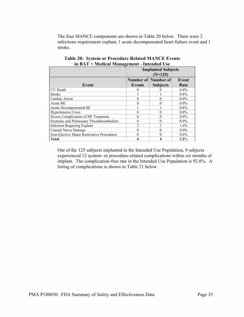
The four MANCE components are shown in Table 20 below. There were 2 infections requirement explant, 1 acute decompensated heart failure event and 1 stroke.
Table 20: System or Procedure Related MANCE Events
in BAT + Medical Management - Intended Use
Implanted Subjects
(N=125)
Event Number of
Events Number of
Subjects Event Rate
CV Death 0 0 0.0% Stroke 1 1 0.8% Cardiac Arrest 0 0 0.0% Acute MI 0 0 0.0% Acute Decompensated HF 1 1 0.8% Hypertensive Crisis 0 0 0.0% Severe Complication of HF Treatment 0 0 0.0% Systemic and Pulmonary Thromboembolism 0 0 0.0% Infection Requiring Explant 2 2 1.6% Cranial Nerve Damage 0 0 0.0% Non-Elective Major Restorative Procedures 0 0 0.0% Total 4 4 3.2%
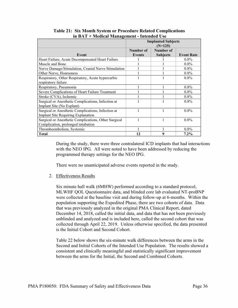
Out of the 125 subjects implanted in the Intended Use Population, 9 subjects experienced 12 system- or procedure-related complications within six months of implant. The complication-free rate in the Intended Use Population is 92.8%. A listing of complications is shown in Table 21 below.
PMA P180050: FDA Summary of Safety and Effectiveness Data Page 36
Table 21: Six Month System or Procedure Related Complications in BAT + Medical Management - Intended Use
Implanted Subjects
(N=125)
Event Number of
Events Number of
Subjects Event Rate Heart Failure, Acute Decompensated Heart Failure 1 1 0.8% Muscle and Bone 1 1 0.8% Nerve Damage/Stimulation, Cranial Nerve Stimulation 1 1 0.8% Other Nerve, Hoarseness 1 1 0.8% Respiratory, Other Respiratory, Acute hypercarbic respiratory failure
1 1 0.8%
Respiratory, Pneumonia 1 1 0.8% Severe Complications of Heart Failure Treatment 1 1 0.8% Stroke (CVA), Ischemic 1 1 0.8% Surgical or Anesthetic Complications, Infection at Implant Site (No Explant)
1 1 0.8%
Surgical or Anesthetic Complications, Infection at Implant Site Requiring Explanation
1 1 0.8%
Surgical or Anesthetic Complications, Other Surgical Complication, prolonged intubation
1 1 0.8%
Thromboembolism, Systemic 1 1 0.8% Total 12 9 7.2%
During the study, there were three contralateral ICD implants that had interactions with the NEO IPG. All were noted to have been addressed by reducing the programmed therapy settings for the NEO IPG. There were no unanticipated adverse events reported in the study.
2. Effectiveness Results
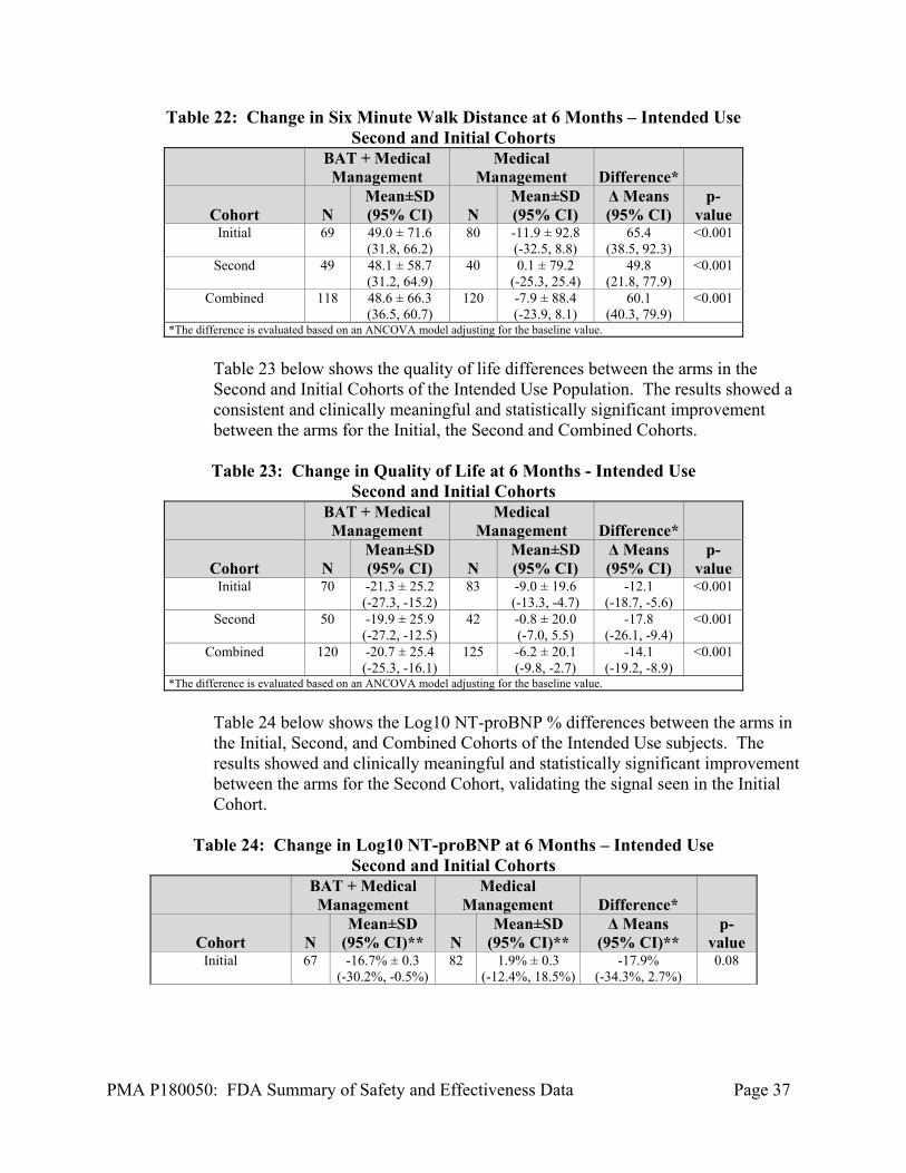
Six minute hall walk (6MHW) performed according to a standard protocol, MLWHF QOL Questionnaire data, and blinded core lab evaluated NT-proBNP were collected at the baseline visit and during follow-up at 6-months. Within the population supporting the Expedited Phase, there are two cohorts of data. Data that was previously analyzed in the original PMA Clinical Report, dated December 14, 2018, called the initial data, and data that has not been previously unblinded and analyzed and is included here, called the second cohort that was collected through April 22, 2019. Unless otherwise specified, the data presented is the Initial Cohort and Second Cohort. Table 22 below shows the six-minute walk differences between the arms in the Second and Initial Cohorts of the Intended Use Population. The results showed a consistent and clinically meaningful and statistically significant improvement between the arms for the Initial, the Second and Combined Cohorts.
PMA P180050: FDA Summary of Safety and Effectiveness Data Page 37
Table 22: Change in Six Minute Walk Distance at 6 Months – Intended Use Second and Initial Cohorts
BAT + Medical Management
Medical Management Difference*
Cohort N Mean±SD (95% CI) N
Mean±SD (95% CI)
Δ Means (95% CI)
p-value
Initial 69 49.0 ± 71.6 (31.8, 66.2)
80 -11.9 ± 92.8 (-32.5, 8.8)
65.4 (38.5, 92.3)
<0.001
Second 49 48.1 ± 58.7 (31.2, 64.9)
40 0.1 ± 79.2 (-25.3, 25.4)
49.8 (21.8, 77.9)
<0.001
Combined 118 48.6 ± 66.3 (36.5, 60.7)
120 -7.9 ± 88.4 (-23.9, 8.1)
60.1 (40.3, 79.9)
<0.001
*The difference is evaluated based on an ANCOVA model adjusting for the baseline value.
Table 23 below shows the quality of life differences between the arms in the Second and Initial Cohorts of the Intended Use Population. The results showed a consistent and clinically meaningful and statistically significant improvement between the arms for the Initial, the Second and Combined Cohorts. Table 23: Change in Quality of Life at 6 Months - Intended Use
Second and Initial Cohorts
BAT + Medical Management
Medical Management Difference*
Cohort N Mean±SD (95% CI) N
Mean±SD (95% CI)
Δ Means (95% CI)
p-value
Initial 70 -21.3 ± 25.2 (-27.3, -15.2)
83 -9.0 ± 19.6 (-13.3, -4.7)
-12.1 (-18.7, -5.6)
<0.001
Second 50 -19.9 ± 25.9 (-27.2, -12.5)
42 -0.8 ± 20.0 (-7.0, 5.5)
-17.8 (-26.1, -9.4)
<0.001
Combined 120 -20.7 ± 25.4 (-25.3, -16.1)
125 -6.2 ± 20.1 (-9.8, -2.7)
-14.1 (-19.2, -8.9)
<0.001
*The difference is evaluated based on an ANCOVA model adjusting for the baseline value.
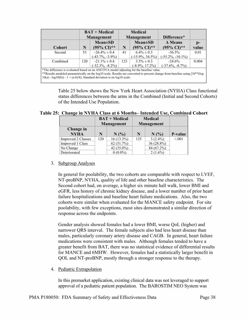
Table 24 below shows the Log10 NT-proBNP % differences between the arms in the Initial, Second, and Combined Cohorts of the Intended Use subjects. The results showed and clinically meaningful and statistically significant improvement between the arms for the Second Cohort, validating the signal seen in the Initial Cohort.
Table 24: Change in Log10 NT-proBNP at 6 Months – Intended Use
Second and Initial Cohorts
BAT + Medical Management
Medical Management Difference*
Cohort N Mean±SD
(95% CI)** N Mean±SD
(95% CI)** Δ Means
(95% CI)** p-
value Initial 67 -16.7% ± 0.3
(-30.2%, -0.5%) 82 1.9% ± 0.3
(-12.4%, 18.5%) -17.9%
(-34.3%, 2.7%) 0.08
PMA P180050: FDA Summary of Safety and Effectiveness Data Page 38
BAT + Medical Management
Medical Management Difference*
Cohort N Mean±SD
(95% CI)** N Mean±SD
(95% CI)** Δ Means
(95% CI)** p-
value Second 53 -26.4% ± 0.4
(-43.7%, -3.9%) 41 6.4% ± 0.3
(-15.9%, 34.5%) -36.5%
(-55.2%, -10.1%) 0.01
Combined 120 -21.1% ± 0.4 (-32.3%, -8.2%)
123 3.3% ± 0.3 (-8.9%, 17.2%)
-24.6% (-37.6%, -8.7%)
0.004
*The difference is evaluated based on an ANCOVA model adjusting for the baseline value. **Results modeled parametrically on the log10 scale. Results are converted to percent change from baseline using [10**(log10(a) - log10(b)) - 1 = (a-b)/b]. Standard deviation is on log10 scale.
Table 25 below shows the New York Heart Association (NYHA) Class functional status differences between the arms in the Combined (Initial and Second Cohorts) of the Intended Use Population.
Table 25: Change in NYHA Class at 6 Months– Intended Use, Combined Cohort
BAT + Medical Management
Medical Management
Change in NYHA N N (%) N N (%) P-value
Improved 2 Classes 120 16 (13.3%) 125 3 (2.4%) <.001 Improved 1 Class 62 (51.7%) 36 (28.8%) No Change 42 (35.0%) 84 (67.2%) Deteriorated 0 (0.0%) 2 (1.6%)
3. Subgroup Analyses
In general for poolability, the two cohorts are comparable with respect to LVEF, NT-proBNP, NYHA, quality of life and other baseline characteristics. The Second cohort had, on average, a higher six minute hall walk, lower BMI and eGFR, less history of chronic kidney disease, and a lower number of prior heart failure hospitalizations and baseline heart failure medications. Also, the two cohorts were similar when evaluated for the MANCE safety endpoint. For site poolability, with few exceptions, most sites demonstrated a similar direction of response across the endpoints. Gender analysis showed females had a lower BMI, worse QoL (higher) and narrower QRS interval. The female subjects also had less heart disease than males, particularly coronary artery disease and CAGB. In general, heart failure medications were consistent with males. Although females tended to have a greater benefit from BAT, there was no statistical evidence of differential results for MANCE and 6MHW. However, females had a statistically larger benefit in QOL and NT-proBNP, mostly through a stronger response to the therapy.
4. Pediatric Extrapolation
In this premarket application, existing clinical data was not leveraged to support approval of a pediatric patient population. The BAROSTIM NEO System was
PMA P180050: FDA Summary of Safety and Effectiveness Data Page 39
developed to treat subjects and patients with heart failure. This is a disease that typically afflicts adult patients and was studied with adult subjects only, that were 21 years of age or older. As such, no information on the treatment of pediatric patients that may have heart failure was provided or considered.
E. Financial Disclosure
The Financial Disclosure by Clinical Investigators regulation (21 CFR 54) requires applicants who submit a marketing application to include certain information concerning the compensation to, and financial interests and arrangement of, any clinical investigator conducting clinical studies covered by the regulation. The pivotal clinical study included 504 investigators. None of the clinical investigators had disclosable financial interests/arrangements as defined in sections 54.2(a), (b), (c), and (f). The information provided does not raise any questions about the reliability of the data.
XI. PANEL MEETING RECOMMENDATION AND FDA’S POST-PANEL ACTION
In accordance with the provisions of section 515(c)(3) of the act as amended by the Safe Medical Devices Act of 1990, this PMA was not referred to the Circulatory System Devices Panel, an FDA advisory committee, for review and recommendation because the information in the PMA substantially duplicates information previously reviewed by this panel.
XII. CONCLUSIONS DRAWN FROM PRECLINICAL AND CLINICAL STUDIES A. Effectiveness Conclusions
For Intended Use Population the three effectiveness endpoints, the BAT + MM arm consistently showed significant improvement from baseline to six months, while the Medical Management arm showed virtually no change. In the Second cohort, the difference between the device was +50 meters (p<0.001) in 6MHW, -18 points in MLWHF QOL (p<0.001) and -37% for NT-proBNP (p=0.01). These improvements were clinically significant within the BAT + MM arm, as well as between the arms. These effectiveness results were consistent across the Initial and the Second cohorts.
B. Safety Conclusions
The risks of the device are based on nonclinical laboratory and/or animal studies data collected in a clinical studies conducted to support PMA approval as described above. The nonclinical laboratory and animal studies met their prespecified requirements or acceptance criteria. Safety in the Intended Use Population was demonstrated in the BeAT-HF trial in the 125 implanted subjects with a system- or procedure-related MANCE-free rate of 96.8%. There were four MANCE events related to the system and/or the procedure
PMA P180050: FDA Summary of Safety and Effectiveness Data Page 40
of which all recovered, three with no residual effect. There were no deaths in the BAT + MM associated with either system or the procedure. There were no unanticipated adverse events.
C. Benefit-Risk Determination
The probable benefits of the device are based on data collected in the BeAT-HF trial, conducted to support PMA approval as described above. The device benefits included symptom reductions or improvements in the form of increased subject walking distance (functional capacity) and improved subject QOL. These endpoints were met and were shown to be both statistically significant and clinically relevant across the entire study population. In particular, subjects in the identified Intended Use Population, demonstrated the same statistically significant and clinically relevant improvement for both walking distance and QOL through 6-months of follow-up, in both Initial and Second cohorts. Additionally, as reported in the Intended Use Population, NT-proBNP provided objective evidence of device effect as validated by the Second Cohort’s statistically significant results. The probable risks of the device are based on data collected in a clinical study conducted to support PMA approval as described above. In particular, for the Intended Use Population the primary safety metric MANCE, met the established acceptance criteria. The observed risks of the devices were similar to those types of events that are seen with implantation and use of a standard pacemaker or other implantable pulse generator systems, with the exception that the BAROSTIM NEO System is all extravascular. These events were observed over the course of the 3 years of the trial and were all deemed to be consistent with other similar therapies and met all established acceptance criteria for the trial. Additionally, there were no unanticipated adverse events seen in the trial. 1. Patient Perspectives
The patient perspective was captured in this trial by collection and reporting of the subject QOL data. This data demonstrated that the BAT+MM treated subjects QOL improved during the course of the trial and was both clinically and statistically significant from baseline and when compared to the MM control arm.
In conclusion, given the available information above, the data support that for the BAROSTIM NEO System used in the Intended Use Population for the improvement of symptoms in patients who suffer with heart failure, the data support that for the indication for use of the device, the probable benefits outweight the probable risks.
D. Overall Conclusions
The data in this application support the reasonable assurance of safety and effectiveness of this device when used in accordance with the instructions for use and indications for use.
PMA P180050: FDA Summary of Safety and Effectiveness Data Page 41
XIII. CDRH DECISION
CDRH issued an approval order on August 16, 2019. The final conditions of approval cited in the approval order are described below.
The Extended Phase BeAT-HF is a prospective, randomized controlled trial intended to assess morbidity and mortality data collected for the BAROSTIM NEO System. The total number of randomized subjects needed for the study is 480. Subjects will complete follow up visits semi-annually. Success is determined by rejection of the null hypothesis with a lower rate of events in the treatment arm compared to the control arm. The protocol was approved under G120010/S034 on February 27, 2019, Document #: 360043-001 Rev. F v0.1 dated 25 Jan 2019.
The applicant is required to meet the following timeline for Extended Phase BeAT-HF: 100% of subjects randomized by May 1, 2020; and Submission of the final study report within 3 months from study completion
(i.e., up to 320 events adjudicated, as determined by the statistical analysis plan).
In addition, the applicant is required to submit periodic reports on the progress of Extended Phase BeAT-HF as follows: PAS Progress Reports every six (6) months until subject enrollment has been
completed and annually thereafter. If the enrollment milestone is not met, the applicant must begin submitting
quarterly enrollment status reports (i.e., every 3 months), in addition to their periodic (6-months) PAS Progress Reports, until FDA notifies them otherwise.
The applicant’s manufacturing facilities have been inspected and found to be in compliance with the device Quality System (QS) regulation (21 CFR 820).
XIV. APPROVAL SPECIFICATIONS
Directions for use: See device labeling. Hazards to Health from Use of the Device: See Indications, Contraindications, Warnings, Precautions, and Adverse Events in the device labeling. Post-approval Requirements and Restrictions: See approval order.
XV. REFERENCES
i Tracy CM, Epstein AE, Darbar D, et al. 2012 ACCF/AHA/HRS Focused Update Incorporated Into the ACCF/AHA/HRS 2008 Guidelines for Device-Based Therapy of
PMA P180050: FDA Summary of Safety and Effectiveness Data Page 42
Cardiac Rhythm Abnormalities: A Report of the American College of Cardiology Foundation/American Heart Association Task Force on Practice Guidelines and the Heart Rhythm Society. J Am Coll Cardiol. 2013;61(3):e6-e75. doi:10.1016/j.jacc.2012.11.007. ii Brignole M, Auricchio A, Baron-Esquivias G, Bordachar P, Boriani G, Breithardt OA, et al. 2013 ESC Guidelines on cardiac pacing and cardiac resynchronization therapy: the Task Force on cardiac pacing and resynchronization therapy of the European Society of Cardiology (ESC). Developed in collaboration with the European Heart Rhythm Association (EHRA). Eur Heart J. 2013;34(29):2281-329.