Embed Size (px)
Citation preview

Summary of EIC Electron PolarimetrySummary of EIC Electron Polarimetry Workshop
A t 23 24 2007August 23‐24, 2007 hosted by the University of Michigan (Ann Arbor)
http://eic.physics.lsa.umich.edu/
Wolfgang LorenzonUniversity of Michigan
PSTP 2007PSTP 2007

Goals of Workshop
• Which design/physics processes are appropriate for EIC?
• What difficulties will different design parameters present?
• What is required to achieve sub‐1% precision?
• What resources are needed over next 5 years to achieve CD0 by• What resources are needed over next 5 years to achieve CD0 by the next Long Range Plan Meeting (2013?)
→ Exchange of ideas among experts in electron polarimetry and source & accelerator design to examine existing and novel electron beam polarization measurement schemes.
9/14/2007 2W. Lorenzon PSTP 2007

Workshop ParticipantsFirst Name Last Name Affiliation
Kieran Boyle Stony Brook Abhay Deshpande RIKEN-BNL / Stony Brooky p yChristoph Montag BNLBrian Ball Michigan Wouter Deconinck MichiganAvetik Hayrapetyan MichiganAvetik Hayrapetyan MichiganWolfgang Lorenzon MichiganEugene Chudakov Jefferson Lab Dave Gaskell Jefferson Lab Joseph Grames Jefferson LabJeff Martin University of Winnipeg Anna Micherdzinska University of Winnipeg Kent Paschke University of Virginia Yuhong Zhang Jefferson Lab Wilbur Franklin MIT Bates
BNL: 3 / HERA: 4 / Jlab: 7 / MIT-Bates: 1A l t /S 3 P l i t 12
9/14/2007 3W. Lorenzon PSTP 2007
Accelerator/Source: 3 Polarimetry: 12

EIC Objectives
• e‐p and e‐ion collisions
• cm energies: 20–100 GeV
– 10 GeV (~3–20 GeV) electrons/positrons
– 250 GeV (~30–250 GeV) protons
– 100 GeV/u (~50‐100 GeV/u) heavy ions (eRHIC) / (~15‐170 GeV/u) light ions (3He)
P l i d l d li h i b• Polarized lepton, proton and light ion beams
• Longitudinal polarization at Interaction Point (IP): ~70% or better
B h ti 3 35• Bunch separation: 3–35 ns
• Luminosity: L(ep) ~1033‐34 cm‐2 s‐1 per IP
Goal: 50 fb‐1 in 10 yearsGoal: 50 fb in 10 years
9/14/2007 4W. Lorenzon PSTP 2007

Electron Ion Collider• Addition of a high energy polarized electron beam facility to the
existing RHIC [eRHIC]
Additi f hi h h d / l b f ilit t J ff• Addition of a high energy hadron/nuclear beam facility at Jefferson Lab [ELectron Ion Collider: ELIC]– will drastically enhance our ability to study fundamental and universal aspects
of QCDof QCD
ELICELIC
9/14/2007 5W. Lorenzon PSTP 2007

How to measure polarization of e-/e+ beams?
• Macroscopic:– Polarized electron bunch: very weak dipolePolarized electron bunch: very weak dipole
(~10‐7 of magnetized iron of same size)
• Microscopic:spin dependent scattering processes– spin‐dependent scattering processessimplest → elastic processes:‐ cross section large‐ simple kinematic propertiesp p p‐ physics quite well understood
– three different targets used currently:1. e‐ ‐ nucleus: Mott scattering 100 – 300 keV (5 MeV: JLab)
spin‐orbit coupling of electron spin with (large Z) target nucleus
2. e± ‐ electrons: Møller (Bhabha) Scat. MeV – GeVatomic electron in Fe (or Fe‐alloy) polarized by external magnetic field
3. e ± ‐ photons: Compton Scattering > GeV3. e photons: Compton Scattering > GeVlaser photons scatter off lepton beam
9/14/2007 6W. Lorenzon PSTP 2007

Electron Polarimetry
Many polarimeters are, have been in use, or a planned:
• Compton Polarimeters: LEP mainly used as machine tool for resonant depolarization
SLAC SLD 46 GeV
DESY HERA, storage ring 27.5 GeV (three polarimeters)
JLab Hall A < 8 GeV / Hall C < 12 GeV
Bates South Hall Ring < 1 GeV g
Nikhef AmPS, storage ring < 1 GeV
• Møller / Bhabha Polarimeters:ø /Bates linear accelerator < 1 GeV
Mainz Mainz Microtron MAMI < 1 GeV
Jlab Hall A, B, C, ,
9/14/2007 7W. Lorenzon PSTP 2007

Compton vs Moller Polarimetry532 nm HERA
(27.5 GeV)
EIC HERA -7/9(10 GeV)
Jlab
EIC7/9
x 2maeE E Eλγ ∝Compton edge:
9/14/2007 8W. Lorenzon PSTP 2007

Polarimeter RoundupLaboratory Polarimeter Relative precision Dominant systematic uncertainty
JLab 5 MeV Mott ~1% Sherman function
JLab Hall A Møller ~2‐3% target polarization
JLab Hall B Møller 1.6% (?) target polarization, Levchuk effect
JL b H ll C M ll 0 5% (→1 3%) l i i L h k ff hi hJLab Hall C Møller 0.5% (→1.3%) target polarization, Levchuk effect, high current extrapolation
JLab Hall A Compton 1% (@ > 3 GeV) detector acceptance + response
HERA LPol Compton 1 6% analyzing powerHERA LPol Compton 1.6% analyzing power
HERA TPol Compton 3.1% focus correction + analyzing power
HERA Cavity LPol Compton ? still unknown
h f dMIT‐Bates Mott ~2% Sherman function + detector response
MIT‐Bates Transmission >5% analyzing power
MIT‐Bates Compton ~3‐4% analyzing power
SLAC Compton 0.5% analyzing power

The “Spin Dance” Experiment (2000)
SourceStrained GaAs photocathode (λ = 850 nm, Pb >75 %)
Phys. Rev. ST Accel. Beams 7, 042802 (2004)
b
Accelerator
5.7 GeV, 5 pass recirculation
Polarimeter I P P P
Wien filter in injector was varied from ‐110o to 110o
to vary degree of longitudinal polarization in each hall
Polarimeter I ave Px Py Pz
Injector Mott 2 μA x xHall A Compton 70 μA xHall A Moller 1 μA x x
to vary degree of longitudinal polarization in each hall
→ precise cross‐comparison of JLab polarimeters
9/14/2007 10W. Lorenzon PSTP 2007
Hall B Moller 10 nA x xHall C Moller 1 μA x

Polarization ResultsResults shown include statistical errors only→ some amplification to account for non-sinusoidal behavior
Statistically significant disagreement
Systematics shown:
MottM ll C 1%Møller C 1% ComptonMøller B 1.6%Møller A 3%
Even including systematic errors, discrepancy still significant

Additional Cross‐Hall Comparisons (2006)• During G0 Backangle, performed “mini‐spin dance” to ensure purely longitudinal
polarization in Hall C
• Hall A Compton was also online use, so they participated as wellp , y p p
• Relatively good agreement between Hall C Møller and Mott and between Hall C Møller and Compton

Lessons Learned• Include polarization diagnostics and monitoring in beam lattice design
– minimize bremsstrahlung and synchrotron radiation• Measure beam polarization continuously
protects against drifts or systematic current dependence to polarization– protects against drifts or systematic current‐dependence to polarization• Providing/proving precision at 1% level very challenging• Multiple devices/techniques to measure polarization
– cross‐comparisons of individual polarimeters are crucial for testing systematics of each de iceeach device
– at least one polarimeter needs to measure absolute polarization, others might do relative measurements
• Compton Scatteringadvantages: laser polarization can be measured accurately pure QED non invasive– advantages: laser polarization can be measured accurately – pure QED – non‐invasive, continuous monitor – backgrounds easy to measure – ideal at high energy / high beam currents
– disadvantages: at low beam currents: time consuming – at low energies: small asymmetries –systematics: energy dependent
• Møller Scattering– advantages: rapid, precise measurements – large analyzing power – high B field Fe target:
~0.5% systematic errors– disadvantages: destructive – low currents only – target polarization low (Fe foil: 8%) –
Levchuk eff.
• New ideas are always welcome!• New ideas are always welcome!
9/14/2007 13W. Lorenzon PSTP 2007

New Ideas
9/14/2007 14W. Lorenzon PSTP 2007

New Fiber Laser Technology (Hall C)
Electron Beam LaserBeam
Jeff Martin
30 l t 499 MH30 ps pulses at 499 MHz
‐ external to beamline vacuum (unlike
Gain switched
9/14/2007 15W. Lorenzon PSTP 2007
Hall A cavity) → easy access‐ excellent stability, low maintenance

Electron PolarimetryKent PaschkeKent Paschke
9/14/2007 16W. Lorenzon PSTP 2007
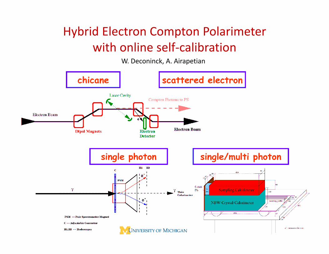
Hybrid Electron Compton Polarimeterwith online self calibrationwith online self‐calibration
W. Deconinck, A. Airapetian
9/14/2007 17W. Lorenzon PSTP 2007

Summary
• Electron beam polarimetry between 3 – 20 GeV seems possible at 1%level: no apparent show stoppers (but not easy)level: no apparent show stoppers (but not easy)
• Imperative to include polarimetry in beam lattice design
• Use multiple devices/techniques to control systematics
• Iss es• Issues: – crossing frequency 3–35 ns: very different from RHIC and HERA
– beam‐beam effects (depolarization) at high currents
b i f b h ff l i i h i ?– crab‐crossing of bunches: effect on polarization, how to measure it?
– measure longitudinal polarization only, or transverse needed as well
– polarimetry before, at, or after IP
d di d IP d f i ?– dedicated IP, separated from experiments?
• Workshop attendees agreed to be part of e‐pol task force– W. Lorenzon coordinator of initial activities and directions
– design efforts and simulations just started
9/14/2007 18W. Lorenzon PSTP 2007