Embed Size (px)
Citation preview

PBN/GNSS TF/5-IP/4 2/04/2013
International Civil Aviation Organization Performance Based Navigation/Global Navigation Satellite System Task Force (PBN/GNSS TF) Fifth Meeting
(Cairo, Egypt, 15 - 17 April 2013)
Agenda Item 3: Developments in PBN and GNSS
PROPOSALS FOR THE AMENDMENT OF ANNEX 10, VOLUME I, CONCERNING GNSS
(Presented by the Secretariat)
SUMMARY
This information paper presents the Meeting with a State Letter from ICAO Headquarters on Proposals for the Amendment of Annex 10, Volume I, concerning the Global Navigation Satellite System (GNSS).
Action by the meeting is at paragraph 2.
1. INTRODUCTION
1.1 The Air Navigation Commission, at the Ninth Meeting of its 191st Session held on 7 November 2012, considered proposals developed by the Navigation Systems Panel (NSP) Working Group of the Whole to amend the Standards and Recommended Practices (SARPs) in Annex 10 — Aeronautical Telecommunications, Volume I — Radio Navigation Aids concerning the Global Navigation Satellite System (GNSS).
2. ACTION BY THE MEETING
2.1 The meeting is invited to take note of the State Letter provided in Appendix A to this information paper.
----------------

999 University Street
Montréal, Quebec
Canada H3C 5H7
Tel.: +1 514-954-8219
Fax: +1 514-954-6077
E-mail: [email protected]
www.icao.int
International
Civil Aviation
Organization
Organisation
de l’aviation civile
internationale
Organización
de Aviación Civil
Internacional
Международная
организация
гражданской
авиации
Tel.: +1 514-954-8219, ext. 6712
Ref.: AN 7/1.3.101-12/68 12 December 2012 Subject: Proposals for the amendment of Annex 10, Volume I, concerning the global navigation satellite system (GNSS) Action required: Comments to reach Montréal by 29 March 2013 Sir/Madam,
1. I have the honour to inform you that the Air Navigation Commission, at the ninth meeting of its 191st Session held on 7 November 2012, considered proposals developed by the Navigation Systems Panel (NSP) Working Group of the Whole to amend the Standards and Recommended Practices (SARPs) in Annex 10 — Aeronautical Telecommunications, Volume I — Radio Navigation Aids concerning the global navigation satellite system (GNSS). The Commission authorized their transmission to Member States and appropriate international organizations for comments.
2. Background information on elements of the proposal is included for your convenience in Attachment A. The proposed amendments, as modified by the Air Navigation Commission, are contained in Attachment B, and their rationales are contained in Attachment C.
3. It should be noted that minimal financial impact is anticipated from the proposed changes.
4. In examining the proposed amendments, you should not feel obliged to comment on editorial aspects as such matters will be addressed by the Air Navigation Commission during its final review of the draft amendment.
5. May I request that any comments you may wish to make on the amendment proposals be dispatched to reach me not later than 29 March 2013. The Air Navigation Commission has asked me to specifically indicate that comments received after the due date may not be considered by the Commission and the Council. In this connection, should you anticipate a delay in the receipt of your reply, please let me know in advance of the due date.
APPENDIX A PBN GNSS TF/5-IP/4 APPENDIX A

- 2 -
6. For your information, the proposed amendment to Annex 10, Volume I, is envisaged for applicability on 13 November 2014. Any comments you may have thereon would be appreciated.
7. The subsequent work of the Air Navigation Commission and the Council would be greatly facilitated by specific statements on the acceptability or otherwise of the proposals. Please note that, for the review of your comments by the Air Navigation Commission and the Council, replies are normally classified as “agreement with or without comments”, “disagreement with or without comments” or “no indication of position”. If in your reply the expressions “no objections” or “no comments” are used, they will be taken to mean “agreement without comment” and “no indication of position”, respectively. In order to facilitate proper classification of your response, a form has been included in Attachment D which may be completed and returned together with your comments, if any, on the proposals in Attachment B.
Accept, Sir/Madam, the assurances of my highest consideration.
Raymond Benjamin Secretary General
Enclosures: A — Background
B — Proposed amendment to Annex 10, Volume I C — Rationale D — Response form

ATTACHMENT A to State letter AN 7/1.3.101-12/68
BACKGROUND
1. The proposed amendment contains changes to several sections of the GNSS Standards and Recommended Practices (SARPs), as follows:
a) changes to the global positioning system (GPS) Standard Positioning Service (SPS) specifications;
b) clarification of the GNSS signal-in-space (SIS) continuity requirement for APV and Category I operations;
c) changes to the satellite-based augmentation system (SBAS) message transmission requirements;
d) a new Standard addressing the final approach segment (FAS) data block for SBAS procedures; and
e) modifications to the guidance material on signal quality monitoring (SQM).
2. The changes to the GPS SPS specifications are intended to align the Annex 10 material with the 4th edition of the document Global Positioning System Standard Positioning Service – Performance Standard, which specifies the actual performance of GPS. The main changes include improvements of some of the existing performance Standards and introduction of updates to reflect the actual operation of the GPS satellites with regard to broadcasting of integrity alerts.
3. The clarification to the GNSS SIS continuity requirements applies to the conditions of applicability of the GNSS SIS continuity requirements for approach operations with vertical guidance and for Category I precision approach in Appendix B and is achieved by referencing the relevant section of the guidance material in Attachment D.
4. The changes to the SBAS message transmission requirements introduce a requirement for SBAS satellites to transmit Type 9 (ephemeris) messages, even if they do not provide a ranging function, and to ensure that the contents of the Type 9 and Type 17 (almanac) messages are consistent. Furthermore, new requirements to support the use of SBAS satellites in higher inclination orbits are introduced.
5. The new Standard addressing the FAS data block for SBAS procedures provides a self-standing specification for the FAS data block format to be used for SBAS procedures, replacing the current guidance material referencing the GBAS FAS data block format Standard.
6. The modifications to the guidance material on SQM introduce more stringent tracking constraints for GBAS airborne receivers.
— — — — — — — —

ATTACHMENT B to State letter AN 7/1.3.101-12/68
PROPOSED AMENDMENT TO ANNEX 10, VOLUME I
NOTES ON THE PRESENTATION OF THE PROPOSED AMENDMENT
The text of the amendment is arranged to show deleted text with a line through it and new text highlighted with grey shading, as shown below:
1. Text to be deleted is shown with a line through it.
text to be deleted
2. New text to be inserted is highlighted with grey shading.
new text to be inserted
3. Text to be deleted is shown with a line through it followed by the replacement text which is highlighted with grey shading.
new text to replace existing text

B-2
INTERNATIONAL STANDARDS
AND RECOMMENDED PRACTICES
AERONAUTICAL TELECOMMUNICATIONS
ANNEX 10
TO THE CONVENTION ON INTERNATIONAL CIVIL AVIATION
VOLUME I (RADIO NAVIGATION AIDS)
. . .
CHAPTER 3. SPECIFICATIONS FOR RADIO NAVIGATION AIDS . . .
3.7 Requirements for the Global Navigation Satellite System (GNSS) . . .
3.7.3.1 GPS Standard Positioning Service (SPS) (L1) 3.7.3.1.1 Space and control segment accuracy Note.— The following accuracy standards do not include atmospheric or receiver errors as described in Attachment D, 4.1.2. They apply under the condition that marginal and unhealthy satellites are excluded from the position solution as specified in Appendix B, 3.1.3.1.1. 3.7.3.1.1.1 Positioning accuracy. The GPS SPS position errors shall not exceed the following limits:
Global average 95% of the time
Worst site 95% of the time
Horizontal position error Vertical position error
139 m (43 30 ft) 22 15 m (72 49 ft)
36 17 m (118 56 ft) 77 37 m (253 121 ft)
3.7.3.1.1.2 Time transfer accuracy. The GPS SPS time transfer errors shall not exceed 40 nanoseconds 95 per cent of the time. 3.7.3.1.1.3 Range domain accuracy. The range domain error shall not exceed the following limits:
a) range error of any satellite — the larger of: 30 m (100 ft) with reliability specified in 3.7.3.1.3;
— 30 m (100 ft); or — 4.42 times the broadcast user range accuracy (URA), not to exceed 150 m (490 ft); b) 95th percentile range rate error of any satellite — 0.02 0.006 m (0.07 0.02 ft) per second (global
average);

B-3 c) 95th percentile range acceleration error of any satellite — 0.007 0.002 m (0.02 0.006 ft) per
second-squared (global average); and d) root-mean-square 95th percentile range error over allfor any satellites over all time differences
between time of data generation and time of use of data — 6 m (20 ft) 7.8 m (26 ft) (global average).
3.7.3.1.2 Availability. The GPS SPS availability shall be as follows:
≥99 per cent horizontal service availability, average location (36 17 m 95 per cent threshold)
≥99 per cent vertical service availability, average location (77 37 m 95 per cent threshold)
≥90 per cent horizontal service availability, worst-case location (36 17 m 95 per cent threshold)
≥90 per cent vertical service availability, worst-case location (77 37 m 95 per cent threshold)
3.7.3.1.3 Reliability. The GPS SPS reliability shall be within the following limits: a) frequency of a major service failure — not more than three per year for the constellation (global
average); ba) reliability — at least 99.94 per cent (global average); and cb) reliability — at least 99.79 per cent (worst single point average). 3.7.3.1.4 Integrity (major service failure). The probability that the user range error (URE) of any satellite will exceed 4.42 times the upper bound on the user range accuracy (URA) broadcast by that satellite without an alert received at the user receiver antenna within 10 seconds shall not exceed 1×10⁻⁵ per hour. Note.— The different alert indications are described in U.S. Department of Defense, “Global Positioning System – Standard Positioning Service – Performance Standard”, 4th Edition, September 2008, Section 2.3.4. 3.7.3.1.5 Continuity. The probability of losing GPS SPS signal-in-space (SIS) availability from a slot of the nominal 24-slot constellation due to unscheduled interruption shall not exceed 2×10⁻⁴ per hour. 3.7.3.1.46 Coverage. The GPS SPS shall cover the surface of the earth up to an altitude of 3 000 kilometres. Note.— Guidance material on GPS accuracy, availability, reliability and coverage is given in Attachment D, 4.1.
Renumber paragraphs 3.7.3.1.5 – 3.7.3.1.8
. . .

B-4
Table 3.7.2.4-1 Signal-in-space performance requirements
Typical operation
Accuracy horizontal
95% (Notes 1 and 3)
Accuracy vertical
95% (Notes 1 and 3)
Integrity (Note 2)
Time-to-alert (Note 3)
Continuity (Note 4)
Availability (Note 5)
En-route 3.7 km (2.0 NM)
N/A 1 – 1×10⁻⁷/h 5 min 1 – 1× 10⁻⁴/h to 1 – 1×10⁻⁸/h
0.99 to 0.99999
En-route, Terminal
0.74 km (0.4 NM)
N/A 1 – 1× 10⁻⁷/h 15 s 1 – 1× 10⁻⁴/h to 1 – 1×10⁻⁸/h
0.99 to 0.99999
Initial approach, Intermediate approach, Non-precision approach (NPA), Departure
220 m (720 ft)
N/A 1 – 1× 10⁻⁷/h
10 s 1 – 1×10⁻⁴/h to 1 – 1×10⁻⁸/h
0.99 to 0.99999
Approach operations with vertical guidance (APV-I)
16.0 m (52 ft)
20 m (66 ft)
1 – 2× 10⁻⁷ in any
approach
10 s 1 – 8× 10⁻⁶ per 15 s
0.99 to 0.99999
Approach operations with vertical guidance (APV-II)
16.0 m (52 ft)
8.0 m (26 ft)
1 – 2× 10⁻⁷ in any
approach
6 s 1 – 8× 10⁻⁶ per 15 s
0.99 to 0.99999
Category I precision approach (Note 7)
16.0 m (52 ft)
6.0 m to 4.0 m (20 ft to 13 ft)
(Note 6)
1 – 2× 10⁻⁷ in any
approach
6 s 1 – 8× 10⁻⁶ per 15 s
0.99 to 0.99999
NOTES.—
. . .
4. Ranges of values are given for the continuity requirement for en-route, terminal, initial approach, NPA anddeparture operations, as this requirement is dependent upon several factors including the intended operation, trafficdensity, complexity of airspace and availability of alternative navigation aids. The lower value given is theminimum requirement for areas with low traffic density and airspace complexity. The higher value given isappropriate for areas with high traffic density and airspace complexity (see Attachment D, 3.4.2). Continuityrequirements for APV and Category I operations apply to the average risk (over time) of loss of service, normalizedto a 15-second exposure time (see Attachment D, 3.4.3). APV and Category I operations may be supported in areaswhere the continuity requirements are not met, upon consideration of appropriate mitigation measures (seeAttachment D, 3.4.3).

B-5
APPENDIX B. TECHNICAL SPECIFICATIONS FOR THE GLOBAL NAVIGATION SATELLITE SYSTEM (GNSS)
. . .
3.1.3.1 GNSS (GPS) RECEIVER 3.1.3.1.1 Satellite exclusion. The receiver shall exclude any satellite designated marginal or unhealthy by the GPS satellite ephemeris health flag. . . .
3.5.7.1 GENERAL . . .
3.5.7.1.3 “Do Not Use”. SBAS shall broadcast a “Do Not Use” message (Type 0 message) when necessary to inform users not to use the SBAS satellite ranging function and its broadcast data.
3.5.7.1.4 The Doppler shift in the GEO satellite signal seen at any fixed location within the GEO footprint for any GEO shall not exceed ±450 Hz.
Note .— This maximum Doppler shift corresponds approximately to the maximum GEO satellite
orbit inclination that can be supported by the coding ranges for Type 9 and Type 17 messages.
3.5.7.1.5 Geostationary orbit (GEO) ranging function parameters. Each SBAS satellite shall broadcast geostationary orbit (GEO) ranging function parameters (defined in 3.5.4.2).
Note — It is necessary to broadcast geostationary orbit ranging function parameters even when a
ranging function is not provided, so that airborne receivers may implement a positive identification of the broadcasting SBAS satellite. When ranging is not provided, the accuracy of the Type 17 data (and Type 9 data) only needs to support the acquisition of the satellite.
3.5.7.1.5.1 The error in the Doppler shift of a GEO satellite derived from any Type 9 message that
has not timed out, with respect to the true GEO Doppler shift seen at any fixed location within the GEO footprint, shall not exceed ±210 Hz.
3.5.7.1.46 Almanac data. Each SBAS satellite shall broadcast almanac data for SBAS satellites (defined in 3.5.4.3) for all SBAS satellites of the same service provider. with error less than 150 km (81 NM) of the true satellite position. Unused almanac slots in Type 17 messages shall be coded with a PRN code number of “0”. The health and status shall indicate satellite status and the service provider as defined in 3.5.4.3.
3.5.7.1.6.1 The error in the estimated position of the satellite derived from any Type 17 message broadcast within the previous 15 minutes, with respect to the true satellite position, shall not exceed 3,000 km.
3.5.7.1.6.2 The separation distance between the estimated position of the satellite derived from
any Type 17 message broadcast within the previous 15 minutes and the position of the satellite derived

B-6 from the GEO ranging parameters in any Type 9 message that has not timed out shall not exceed 200 km.
3.5.7.1.6.3 The error in the Doppler shift of a GEO satellite derived from any Type 17 message
broadcast within the previous 15 minutes, with respect to the true GEO Doppler shift seen at any fixed location within the GEO footprint, shall not exceed ±210 Hz.
3.5.7.1.6.4 SBAS shall not broadcast almanac data for any SBAS satellite from a different service
provider for which the position estimated from the almanac data broadcast within the previous 15 minutes would be within 200 km of the position of any of its own GEOs as derived from the GEO ranging parameters from any Type 9 message that has not timed out.
3.5.7.1.6.5 Where the estimated position of a GEO satellite providing a ranging function, derived
from the Type 17 message broadcast within the previous 15 minutes, is within 200 km of the position of another GEO satellite of the same service provider, derived from a Type 9 message for this GEO that has not timed out, the GEO UDRE value shall be set sufficiently large to account for the possibility that a user could misidentify the PRN of the GEO providing the ranging function.
3.5.7.1.6.6 The health and status parameter shall indicate the satellite status and the service
provider identifier, as defined in 3.5.4.3.
3.5.7.1.6 Unused almanac slots in Type 17 messages shall be coded with a PRN code number of “0”.
3.5.7.1.6.8 The service provider shall ensure the correctness of the service provider ID broadcast in
any almanac. 3.5.7.1.5 Recommendation.— SBAS should broadcast almanac data for all SBAS satellites,
regardless of the service provider. . . .
Table B-54. Data broadcast intervals and supported functions
Data type
Maximum broadcast interval Ranging
GNSS satellite status
Basic differential correction
Precise differential correction
Associated message
types
. . .
GEO ranging function data 120 s R R R R 9
. . .
Notes.— 1. “R” indicates that the data must be broadcast to support the function. . . .
. . .
3.5.7.3 GNSS satellite status function. If an SBAS provides a satellite status function, it shall also comply with the requirements contained in this section.
Note — An SBAS may be able to provide integrity on some GPS satellites that are designated either marginal or unhealthy.

B-7 . . .
3.5.8.1 SBAS-capable GNSS receiver. Except as specifically noted, the SBAS-capable GNSS receiver shall process the signals of the SBAS and meet the requirements specified in 3.1.3.1 (GPS receiver) and/or 3.2.3.1 (GLONASS receiver). Pseudo-range measurements for each satellite shall be smoothed using carrier measurements and a smoothing filter which deviates less than 0.1 metre within 200 seconds after initialization, relative to the steady-state response of the filter defined in 3.6.5.1 in the presence of drift between the code phase and integrated carrier phase of up to 0.01 metre per second.
3.5.8.1.1 GEO satellite acquisition. The receiver shall be able to acquire and track GEO satellites
for which a stationary receiver at the user receiver location would experience a Doppler shift as large as ±450 Hz.
3.5.8.1.12 Conditions for use of data. The receiver shall use data from an SBAS message only if
the CRC of this message has been verified. Reception of a Type 0 message from an SBAS satellite shall result in deselection of that satellite and all data from that satellite shall be discarded for at least 1 minute. For GPS satellites, the receiver shall apply long-term corrections only if the IOD matches both the IODE and 8 least significant bits of the IODC. For GLONASS satellites, the receiver shall apply long-term corrections only if the time of reception (tr) of the GLONASS ephemeris is inside the following IOD validity interval, as defined in 3.5.4.4.1:
tLT – L – V ≤ tr ≤ tLT – L
Note 1.— For SBAS satellites, there is no mechanism that links GEO ranging function data (Type 9 message) and long-term corrections.
Note 2.— This requirement does not imply that the receiver has to stop tracking the SBAS satellite. 3.5.8.1.2.1 SBAS satellite identification. Upon acquisition or re-acquisition of an SBAS satellite,
the receiver shall not use SBAS satellite data unless the calculated separation between the satellite position derived from its GEO ranging function parameters and the satellite position derived from the almanac message most recently received from the same service provider within the last 15 minutes is less than 200 km.
Note. — This check ensures that a receiver will not mistake one SBAS satellite for another due to
cross-correlation during acquisition or re-acquisition.
Renumber paragraphs 3.5.8.1.1.1 – 3.5.8.1.1.11
. . .
3.5.8.2.4 Almanac data 3.5.8.2.4.1 Recommendation.— The almanac data provided by the SBAS should be used for acquisition. Note.— Health and status information is provided in the GEO almanac data to support acquisition, but need not be used as a condition for use of that satellite does not override or invalidate data provided in other SBAS messages. The use of bits 0 to 2 by airborne equipment is optional; there are no requirements covering their usage. . . .

B-8 3.5.8.3 GNSS satellite status function. The receiver shall exclude satellites from the position solution if they are identified as “Do Not Use” by SBAS. If SBAS-provided integrity is used, the receiver shall not be required to exclude GPS satellites based on the GPS-provided ephemeris health flag as required in 3.1.3.1.1 or to exclude GLONASS satellites based on GLONASS-provided ephemeris health flag as required in 3.2.3.1.1. Note 1.— In the case of a satellite designated marginal or unhealthy by the core satellite constellation(s) health flag, SBAS may be able to broadcast ephemeris and clock corrections that will allow the user to continue using the satellite.
. . .
3.5.8.4.2 Precision approach and APV operations
. . .
3.5.8.4.2.5 The parameters that define the approach path for a single precision approach or APV shall be contained in the FAS data block.
Note 1.— The FAS path is a line in space defined by the landing threshold point/fictitious threshold
point (LTP/FTP), flight path alignment point (FPAP), threshold crossing height (TCH) and glide path angle (GPA). The local level plane for the approach is a plane perpendicular to the local vertical passing through the LTP/FTP (i.e. tangent to the ellipsoid at the LTP/FTP). Local vertical for the approach is normal to the WGS-84 ellipsoid at the LTP/FTP. The glide path intercept point (GPIP) is where the final approach path intercepts the local level plane.
Note 2.— For SBAS, FAS data blocks are stored in airborne databases. The format of the data for validation of a cyclic redundancy check is shown in Attachment D, 6.6. It differs from the GBAS FAS data block in 3.6.4.5.
. . .
3.5.8.4.2.5.1 FAS data block parameters shall be as follows (see Table B-57A): Operation type: straight-in approach procedure or other operation types. Coding: 0 = straight-in approach procedure 1 to 15 = spare SBAS service provider ID: indicates the service provider associated with this FAS data block. Coding: See Table B-27.
14 = FAS data block is to be used with GBAS only. 15 = FAS data block can be used with any SBAS service provider.
Airport ID: the three- or four-letter designator used to designate an airport. Coding: Each character is coded using the lower 6 bits of its IA-5 representation. For each character, bi is
transmitted first, and 2 zero bits are appended after b6, so that 8 bits are transmitted for each character. Only upper case letters, numeric digits and IA-5 “space” are used. The rightmost character is transmitted first. For a three-character airport ID, the rightmost (first transmitted) character shall be IA-5 “space”.

B-9 Runway number: the runway orientation, point in space final approach course, or SBAS circling only
procedure course rounded to the nearest 10 degrees and truncated to two characters. Coding: 01 to 36 = runway number
Note.— For heliport operations, the runway number value is the integer nearest to one tenth of the final approach course, except when that integer is zero, in which case the runway number is 36. Runway letter: the one-letter designator used, as necessary, to differentiate between parallel runways. Coding: 0 = no letter 1 = R (right) 2 = C (centre) 3 = L (left) Approach performance designator: this field is not used by SBAS.
Table B-57A. Final approach segment (FAS) data block
Data content Bits used Range of values Resolution
Operation type 4 0 to 15 1 SBAS provider ID 4 0 to 15 1 Airport ID 32 — — Runway number 6 01 to 36 1 Runway letter 2 — — Approach performance designator 3 0 to 7 1 Route indicator 5 — — Reference path data selector 8 0 to 48 1 Reference path identifier 32 — — LTP/FTP latitude 32 ±90.0° 0.0005 arcsec LTP/FTP longitude 32 ±180.0° 0.0005 arcsec LTP/FTP height 16 –512.0 to 6 041.5 m 0.1 m ΔFPAP latitude 24 ±1.0° 0.0005 arcsec ΔFPAP longitude 24 ±1.0° 0.0005 arcsec Approach TCH (Note 1) 15 0 to 1 638.35 m or
0 to 3 276.7 ft 0.05 m or
0.1 ft Approach TCH units selector 1 — — GPA 16 0 to 90.0° 0.01° Course width 8 80 to 143.75 m 0.25 m ΔLength offset 8 0 to 2 032 m 8 m Horizontal alert Limit (HAL) 8 0 to 51.0 m 0.2 m Vertical Alert Limit (VAL) (Note2)
8 0 to 51.0 m 0.2 m
Final approach segment CRC 32 —
Note 1.— Information can be provided in either feet or metres as indicated by the approach TCH unit selector.
Note 2.— A VAL of 0 indicates that the vertical deviations cannot be used (i.e., a lateral only approach). This does not preclude providing advisory vertical guidance on such approaches, refer to FAA AC 20-138().

B-10 Route indicator: a “blank” or the one-letter identifier used to differentiate between multiple procedures to
the same runway end.
Note.— Procedures are considered to be different even if they only differ by the missed approach segment. Coding: The letter is coded using bits b1 through b5 of its IA-5 representation. Bit b1 is transmitted first.
Only upper case letters, excluding “I” and “O”, or IA-5 “space” (blank) are used. Blank indicates that there is only one procedure to the runway end. For multiple procedures to the same runway end the route indicator is coded using a letter starting from Z and moving backward in the alphabet for additional procedures.
Reference path data selector (RPDS): this field is not used by SBAS. Reference path identifier (RPI): four characters used to uniquely designate the reference path. The four
characters consist of three alphanumeric characters plus a blank or four alphanumeric characters.
Note.— The best industry practice matches the 2nd and 3rd character encoding to the encoded runway number. The last character is a letter starting from A or a “blank.” Coding: Each character is coded using bits b1 through b6 of its IA-5 representation. For each character, b1
is transmitted first, and 2 zero bits are appended after b6 so that 8 bits are transmitted for each character. Only upper case letters, numeric digits and IA-5 “space” are used. The rightmost character is transmitted first. For a three-character reference path identifier, the rightmost (first transmitted) character shall be IA-5 “space”.
Note.— The LTP/FTP is a point over which the FAS path passes at a height above the LTP/FTP
height specified by the TCH. LTP/FTP latitude: the latitude of the LTP/FTP point in arc seconds. Coding: 0 = positive value denotes north latitude. 1 = negative value denotes south latitude. LTP/FTP longitude: the longitude of the LTP/FTP point in arc seconds. Coding: 0 = positive value denotes east longitude. 1 = negative value denotes west longitude. LTP/FTP height: the height of the LTP/FTP above the WGS-84 ellipsoid. Coding: This field is coded as an unsigned fixed-point number with an offset of –512 metres. A value of
zero in this field places the LTP/FTP 512 metres below the earth ellipsoid. Note.— The FPAP is a point at the same height as the LTP/FTP that is used to define the alignment of the approach. The origin of angular deviations in the lateral direction is defined to be 305 metres (1 000 ft) beyond the FPAP along the lateral FAS path. For an approach aligned with the runway, the FPAP is at or beyond the stop end of the runway. ∆FPAP latitude: the difference of latitude of the runway FPAP from the LTP/FTP in arc seconds. Coding: Positive value denotes the FPAP latitude north of LTP/FTP latitude. Negative value denotes the FPAP latitude south of the LTP/FTP latitude.

B-11 ∆FPAP longitude: the difference of longitude of the runway FPAP from the LTP/FTP in arc seconds. Coding: Positive value indicates the FPAP longitude east of LTP/FTP longitude. Negative value indicates the FPAP longitude west of LTP/FTP longitude. Approach TCH: the height of the FAS path above the LTP/FTP defined in either feet or metres as
indicated by the TCH units selector. Approach TCH units selector: the units used to describe the TCH. Coding: 0 = feet 1 = metres Glide path angle (GPA): the angle of the FAS path with respect to the horizontal plane tangent to the
WGS-84 ellipsoid at the LTP/FTP. Course width: the lateral displacement from the path defined by the FAS at the LTP/FTP at which full-
scale deflection of a course deviation indicator is attained. Coding: This field is coded as an unsigned fixed-point number with an offset of 80 metres. A value of
zero in this field indicates a course width of 80 metres at the LTP/FTP. ΔLength offset: the distance from the stop end of the runway to the FPAP. Coding: 1111 1111 = not provided HAL: Horizontal Alert Limit to be used during the approach in meters. VAL: Vertical Alert Limit to be used during the approach in meters. Final approach segment CRC: the 32-bit CRC appended to the end of each FAS data block in order to
ensure approach data integrity. The 32-bit final approach segment CRC shall be calculated in accordance with 3.9. The length of the CRC code shall be k = 32 bits.
The CRC generator polynomial shall be:
G(x) = x32 + x31 + x24 + x22 + x16 + x14 + x8 + x7 + x5 + x3 + x + 1 The CRC information field, M(x), shall be:
M(x) shall be formed from all bits of the associated FAS data block, excluding the CRC. Bits shall be arranged in the order transmitted, such that m1 corresponds to the LSB of the operation type field, and m288 corresponds to the MSB of the Vertical Alert Limit (VAL) field. The CRC shall be ordered such that r1 is the LSB and r32 is the MSB.
3.5.8.4.2.5.2 For precision approach and APV operations, the service provider ID broadcast Type 17 message shall be identical to the service provider ID in the FAS data block, except if ID equals 15 in the FAS data block.

B-12 Note.— For SBAS, FAS data blocks are stored in airborne databases. The format of the data for validation of a cyclic redundancy check is shown in Attachment D, 6.6. It differs from the GBAS FAS data block in 3.6.4.5 in that it contains the SBAS HAL and VAL for the particular approach procedure. For approaches conducted using SBAS pseudo-range corrections, the service provider ID in the FAS data block is the same as the service provider ID broadcast as part of the health and status information in Type 17 message. If the service provider ID in the FAS data block equals 15, then any service provider can be used. If the service provider ID in the FAS data block equals 14, then SBAS precise differential corrections cannot be used for the approach. 3.5.8.4.2.5.3 SBAS FAS data points accuracy. The survey error of all the FAS data points, relative to WGS-84, shall be less than 0.25 metres vertical and 1 metre horizontal.
. . .
3.6.7.2.4 Final approach segment data
3.6.7.2.4.1 FAS data points accuracy. The relative survey error between the FAS data points and the GBAS reference point shall be less than 0.25 metres vertical and 0.40 metres horizontal. 3.6.7.2.4.2 SBAS FAS data points accuracy. For use with SBAS, the survey error of all the FAS data points, relative to WGS-84, shall be less than 0.25 metres vertical and 1 metre horizontal. 3.6.7.2.4.32 Recommendation.— The final approach segment CRC should be assigned at the time of procedure design, and kept as an integral part of the FAS data block from that time onward. 3.6.7.2.4.43 Recommendation.— The GBAS should allow the capability to set the FASVAL and FASLAL for any FAS data block to “1111 1111” to limit the approach to lateral only or to indicate that the approach must not be used, respectively. . . .
ATTACHMENT D. INFORMATION AND MATERIAL FOR GUIDANCE IN THE APPLICATION OF THE
GNSS STANDARDS AND RECOMMENDED PRACTICES . . .
4. GNSS core elements
4.1 GPS Note.— Additional information concerning GPS can be found in the Global Positioning System Standard Positioning Service — Performance Standard, October 2001September 2008, and Interface Control Document Specification (ICDS)-GPS-200CE.

B-13 4.1.1 The performance standard is based upon the assumption that a representative standard positioning service (SPS) receiver is used. A representative receiver has the following characteristics:
a) designed in accordance with ICDIS-GPS-200CE; b) uses a 5-degree masking angle; c) accomplishes satellite position and geometric range computations in the most current realization
of the World Geodetic System 1984 (WGS-84) Earth-Centred, Earth-Fixed (ECEF) coordinate system;
d) generates a position and time solution from data broadcast by all satellites in view; e) compensates for dynamic Doppler shift effects on nominal SPS ranging signal carrier phase and
C/A code measurements; e) excludes GPS marginal and unhealthy satellites from the position solution; f) uses up-to-date and internally consistent ephemeris and clock data for all satellites it is using in its
position solution; and g) loses track in the event that a GPS satellite stops transmitting a trackable signal.
The time transfer accuracy applies to a stationary receiver operating at a surveyed locationthe data in the broadcast navigation message, which relates GPS SPS time to UTC as maintained by the United States Naval Observatory. A 12-channel receiver will meet performance requirements specified in Chapter 3, 3.7.3.1.1.1 and 3.7.3.1.2. A receiver that is able to track four satellites only (Appendix B, 3.1.3.1.2) will not get the full accuracy and availability performance.
Note.— The conditions indicating that a satellite is “marginal” are provided in U.S. Department of Defense, “Global Positioning System – Standard Positioning Service – Performance Standard”, 4th Edition, September 2008, Section 2.3.2.
4.1.2 Position domain Aaccuracy. The position domain accuracy is measured with a representative receiver and a measurement interval of 24 hours for any point within the coverage area. The positioning and timing accuracy are for the signal-in-space (SIS) only and do not include such error sources as: ionosphere, troposphere, interference, receiver noise or multipath. The accuracy is derived based on the worst two of 24 satellites being removed from the constellation and a 6-metre constellation RMS SIS user range error (URE).
4.1.3 Range domain accuracy. The range domain accuracy standard applies to normal operations, which implies that updated navigation data is uplinked to the satellites on regular basis. Range domain accuracy is conditioned by the satellite indicating a healthy status and transmitting C/A code and does not account for satellite failures outside of the normal operating characteristics. Range domain accuracy limits can be exceeded during satellite failures or anomalies while uploading data to the satellite. Exceedance of the range error limit constitutes a major service failure as described in 4.1.6. The range rate error limit is the maximum for any satellite measured over any 3-second interval for any point within the coverage area. The range acceleration error limit is the maximum for any satellite measured over any 3-second interval for any point within the coverage area. The root-mean-square range error accuracy is the average of the RMS URE of all satellites over any 24-hour interval for any point within the coverage area. Under nominal conditions, all satellites are maintained to the same standards, so it is appropriate for availability modelling purposes to assume that all satellites have a 64-metre RMS SIS user range error (URE). The standards are restricted to range domain errors allocated to space and control segments.
4.1.4 Availability. The availability standard applies to normal operations, which implies that updated navigation data is uplinked to the satellites on regular basis. Availability is the percentage of time over any 24-hour interval that the predicted 95 per cent positioning error (due to space and control segment errors) is less than its threshold, for any point within the coverage area. It is based on a 3617-metre horizontal 95 per cent threshold; a 7737-metre vertical 95 per cent threshold; using a representative receiver; and operating within the coverage area over any 24-hour interval. The service availability assumes the worst combination of two satellites out of servicea constellation that meets the criteria in 4.1.4.2.

B-14 4.1.4.1 Relationship to augmentation availability. The availability of ABAS, GBAS and SBAS does not directly relate to the GPS availability defined in Chapter 3, 3.7.3.1.2. States and operators must evaluate the availability of the augmented system by comparing the augmented performance to the requirements. Availability analysis is based on an assumed satellite constellation and the probability of having a given number of satellites.
4.1.4.2 Satellite/constellation availability. Twenty-four operational satellites are available will be maintained on orbit with 0.95 probability (averaged over any day), where a satellite is defined to be operational if it is capable of, but is not necessarily transmitting, a usable ranging signal. At least 21 satellites in the 24 nominal 24 plane/slot positions must be set healthy and must be transmitting a navigation signal with 0.98 probability (yearly averagednormalized annually). At least 20 satellites in the nominal 24 slot positions must be set healthy and must be transmitting a navigation signal with 0.99999 probability (normalized annually). 4.1.5 Reliability. Reliability is the percentage of time over a specified time interval that the instantaneous SPS SIS URE is maintained within the range error limit, at any given point within the coverage area, for all healthy GPS satellites. The reliability standard is based on a measurement interval of one year and the average of daily values within the coverage area. The worst single point average reliability assumes that the total service failure time of 18 hours will be over that particular point (3 failures each lasting 6 hours). 4.1.6 Integrity (Mmajor service failure). An integrity failure (major service failure) is defined to be a condition over a time interval during which a healthy GPS satellite’s ranging signal error (excluding atmospheric and receiver errors) exceeds the range error limit of 4.42 times the upper bound on the user range accuracy (URA) broadcast by a satellite for longer than the allowable time to alert (10 seconds). As defined in Chapter 3, 3.7.3.1.1.3 a), the range error limit is the larger of:
a) 30 m; or
b) 4.42 times the URA, not to exceed 150 m. The probability of 1 10-5 in Chapter 3, 3.7.3.1.4 corresponds to a maximum of 3 major service failures for the entire constellation per year assuming a maximum constellation of 32 satellites. 4.1.7 Continuity. Continuity for a healthy GPS satellite is the probability that the SPS SIS will continue to be healthy without unscheduled interruption over a specified time interval. Scheduled interruptions which are announced at least 48 hours in advance do not contribute to a loss of continuity. 4.1.78 Coverage. The SPS supports the terrestrial coverage area, which is from the surface of the earth up to an altitude of 3 000 km.
. . .
6.6 SBAS final approach segment (FAS) data block 6.6.1 The SBAS final approach segment (FAS) data block for a particular approach procedure is as shown in Table D-1 Appendix B, 3.5.8.4.2.5.1 and Table B-57A. It is the same as the GBAS FAS data block defined in Appendix B, section 3.6.4.5.1 and Table B-66, with the following exceptions. that tThe SBAS FAS data block also contains the HAL and VAL to be used for the approach procedure as described in 6.3.4. SBAS user equipment interprets certain fields differently from GBAS user equipment 6.6.2 FAS data blocks for SBAS and some GBAS approaches are held within a common on-board database supporting both SBAS and GBAS. Within this database, channel assignments must be unique for each approach and coordinated with civil authorities. States are responsible for providing the FAS data for incorporation into the database. The FAS block for a particular approach procedure is described in Appendix B, 3.6.4.5.1 and Table B-66.

B-15 6.6.3 An example of the coding of FAS data block for SBAS is provided in Table D-1. This example illustrates the coding of the various application parameters, including the cyclic redundancy check (CRC). The engineering values for the message parameters in the table illustrate the message coding process.
Table D-1. Example of an SBAS FAS data block
Data content Bits used Range of values Resolution
Operation type 4 0 to 15 1 SBAS provider ID 4 0 to 15 1 Airport ID 32 – – Runway number 6 1 to 36 1 Runway letter 2 – – Approach performance designator 3 0 to 7 1 Route indicator 5 – – Reference path data selector 8 0 to 48 1 Reference path identifier 32 – – LTP/FTP latitude 32 ± 90.0° 0.0005 arcsec LTP/FTP longitude 32 ± 180.0° 0.0005 arcsec LTP/FTP height 16 –512.0 to 6 041.5 m 0.1 m ΔFPAP latitude 24 ± 1.0° 0.0005 arcsec ΔFPAP longitude 24 ± 1.0° 0.0005 arcsec Approach threshold crossing height (TCH) (Note 1)
15 0 to 1 638.35 m (0 to 3 276.7 ft)
0.05 m (0.1 ft)
Approach TCH units selector 1 – – Glide path angle (GPA) 16 0 to 90.0° 0.01° Course width at threshold 8 80.0 to 143.75 m 0.25 m ΔLength offset 8 0 to 2 032 m 8 m Horizontal alert limit (HAL) 8 0 to 50.8 m 0.2 m Vertical alert limit (VAL) (Note 2) 8 0 to 50.8 m 0.2 m Final approach segment CRC 32 – – Note 1.— Information can be provided in either feet or metres as indicated by the approach TCH unit sector. Note 2.— VAL of 0 indicates that the vertical deviations are not to be used (i.e. a lateral guidance only approach).

B-16
DATA CONTENT DESCRIPTION
BITS USED
RANGE OF VALUES
RESOLUTION CODING RULES (Note 5)
PROCEDURE DESIGN VALUES
PROVIDED
FAS DB VALUE USED
BINARY DEFINITION
BINARY REPRESENTATION
(Note 1)
HEXADECIMAL REPRESENTATION
Operation Type 4 [0..15] 1 0 : Straight-in approach procedure 1..15 : Spare
Straight-In 0 m4..m1 0000 08
SBAS provider ID 4 [0..15] 1 0 : WAAS 1 : EGNOS 2 : MSAS 3..13 : Spare 14 : GBAS only 15 : Any SBAS provider
EGNOS 1 m8..m5 0001
Airport ID 32 α1α2α3α4 - α1, α2, α3 = [0..9, A..Z] α4 = [<space>, 0..9, A..Z] DOUT = ASCII value & 3F
LFBO LFBO m40..m33
m32..m25 m24..m17
m16..m9
'L' 00 001100 'F' 00 000110 'B' 00 000010 'O' 00 001111
(Note 2)
F0 40 60 30
Runway number 6 [01..36] 1 - 14 14 m46..m41 001110 72 Runway letter 2 [0..3] 1 0 : No letter
1 : Right (R) 2 : Centre (C) 3 : Left (L)
R 1 m48 m47 01
Approach performance designator
3 [0..7] 1 Not used by SBAS 0 (default value) 0 m51..m49 000 0B
Route indicator 5 α - α = [<space>, A..Z] α ≠ I and α ≠ O
Z Z m56..m52 11010
Reference path data selector
8 [0..48] - Not used by SBAS 0 (default value) 0 m64..m57 00000000 00
Reference path identifier
32 α1α2α3α4 - α1 = [E, M, W] α2, α3 = [0..9] α4 = [<space>, A, B, D..K, M..Q, S..Z] DOUT = ASCII value & 3F
E14A E14A m96..m89 m88..m81 m80..m73 m72..m65
E' 00 000101 '1' 00 110001 '4' 00 110100 'A' 00 000001
(Note 2)
80 2C 8C A0

B-17
DATA CONTENT DESCRIPTION
BITS USED
RANGE OF VALUES
RESOLUTION CODING RULES (Note 5)
PROCEDURE DESIGN VALUES
PROVIDED
FAS DB VALUE USED
BINARY DEFINITION
BINARY REPRESENTATION
(Note 1)
HEXADECIMAL REPRESENTATION
LTP/FTP latitude 32 [-90.0°..90.0°] 0.0005 arcsec DCONV1 = DIN -> rounding method (Note 3) DCONV2 = DCONV1 -> decimal (sec) DOUT = DCONV2 x 2000 N : DOUT S : Two's complement (DOUT)
DIN = 43°38'38.8103" N
DCONV1 = 43°38'38.8105" N
DCONV2 = 157118.8105 sec
DOUT = 314237621
m128..m121
m120..m113 m112..m105
m104..m97
00010010 10111010 11100010 10110101
AD 47 5D 48
LTP/FTP longitude 32 [-180.0°..180.0°] 0.0005 arcsec DCONV1 = DIN -> rounding method (Note 3) DCONV2 = DCONV1 -> decimal (sec) DOUT = DCONV2 x 2000 E : DOUT W : Two's complement (DOUT)
DIN = 001°20'45.3591" E
DCONV1 = 001°20'45.3590" E
DCONV2 = 4845.359 sec DOUT = 9690718
m160..m153
m152..m145 m144..m137
m136..m129
00000000 10010011 11011110 01011110
7A 7B C9 00
LTP/FTP height 16 [-512..6041.5] 0.1m DCONV = round (DIN, resolution) DOUT = (DIN + 512) x 10
DIN = 148.74m DCONV = 148.7 DOUT = 6607
m176..m169
m168..m161 00011001 11001111
F3 98
ΔFPAP latitude 24 [-1.0°..1.0°] 0.0005 arcsec DCONV1 = DiN -> rounding method (Note 3) DCONV2 = DCONV1 -> decimal (sec) DOUT = DCONV2 x 2000 + : DOUT - : Two's complement (DOUT)
DIN = -0°01'37.8973" DCONV1 = -00°01'37.8975"
DCONV2 = -97.8975" DOUT = Two's
complement(195795) DOUT = 16581421
m200..m193
m192..m185 m184..m177
11111101 00000011 00101101
B4 C0 BF
ΔFPAP longitude 24 [-1.0°..1.0°] 0.0005 arcsec DCONV1 = DIN -> rounding method (Note 3) DCONV2 = DCONV1 -> decimal (sec) DOUT = DCONV2 x 2000 + : DOUT - : Two's complement (DOUT)
DIN = 0°01'41.9329" DCONV1 = 0°01'41.9330"
DCONV2 = 101.9330" DOUT = 203866
m224..m217
m216..m209 m208..m201
00000011 00011100 01011010
5A 38 C0
Approach TCH 15 [0..1638.35m] [0..3276.7ft]
0.05m 0.1ft
DCONV = round (DIN, resolution) m : DOUT = DIN x 20 ft : DOUT = DIN x 10
DIN = 15.00m DCONV = 15.00m DOUT = 300
m239..m233
m232..m225 0000001 00101100
34 81
Approach TCH units selector
1 [0,1] - 0 : feet 1 : meters
m 1 m240 1
Glide path angle (GPA)
16 [0..90.00°] 0.01° DCONV = round (DIN, resolution) DOUT = DIN x 100
DIN = 3.00° DCONV = 3.00° DOUT = 300
m256..m249
m248..m241 00000001 00101100
34 80
Course width 8 [80.00m..143.75m] 0.25m DCONV = round (DIN, resolution) DOUT = (DCONV - 80) x 4
DIN = 105.00m DCONV = 105.00m DOUT = 100
m264..m257 01100100 26

B-18
DATA CONTENT DESCRIPTION
BITS USED
RANGE OF VALUES
RESOLUTION CODING RULES (Note 5)
PROCEDURE DESIGN VALUES
PROVIDED
FAS DB VALUE USED
BINARY DEFINITION
BINARY REPRESENTATION
(Note 1)
HEXADECIMAL REPRESENTATION
ΔLength offset 8 [0..2032m] 8m DCONV = round (DIN, resolution) DOUT = (integer division of DCONV
by 8) + 1 DOUT = 255 : not provided value
DIN = 284.86m DCONV = 288m DOUT = 36
m272..m265 00100100 24
Horizontal alert limit (HAL)
8 [0..50.8m] 0.2m DCONV = round (DIN, resolution) DOUT = DIN * 5
DIN = 40.0m DCONV = 40.0m DOUT = 200
m280..m273 11001000 13
Vertical alert limit (VAL)
8 [0..50.8m] 0.2m DCONV = round (DIN, resolution) DOUT = Value * 5 DOUT = 0 : vertical deviations cannot be used
DIN = 50.0m DCONV = 50.0m DOUT = 250
m288..m281 11111010 5F
Final approach segment CRC
32 [0..232-1] DOUT = remainder (P(x) / Q(x)) - - r32..r25
r24..r17 r16..r9
r8..r1
10101110 11000011 01100100 10001111
75 C3 26 F1 (Note 4)
Notes. 1. The rightmost bit is the LSB of the binary parameter value and is the first bit transmitted to the CRC calculator. 2. The two most significant bits of each byte are set to 0 (see bold characters). 3. The rounding methodology is provided in the PANS-OPS (Doc 8168) Volume II. 4. The FAS CRC value is displayed in the order r25..r32, r17..r24, r9..r16, r1..r8 where ri is th ith coefficient of the remainder R(x) as defined in Appendix B, 3.9 . 5. DIN : raw data value, DCONV : converted data value according to coding rules, DOUT : coded data value.

B-19
8.11.4 For aircraft receivers using early-late correlators and tracking GPS satellites, the precorrelation bandwidth of the installation, the correlator spacing and the differential group delay are within the ranges defined in Table D-11, except as noted below.
8.11.4.1 For GBAS airborne equipment using early-late correlators and tracking GPS satellites, the
precorrelation bandwidth of the installation, the correlator spacing and the differential group delay are within the ranges defined in Table D-11, except that the region 1 minimum bandwidth will increase to 4 MHz and the average correlator spacing is reduced to an average of 0.21 chips or instantaneous of 0.235 chips.
. . .
Table D-13B. GPS tracking constraints for GBAS airborne receivers with double-delta correlators
Region
3 dB precorrelation bandwidth,
BW
Average correlator spacing range
(X) (chips)
Instantaneous correlator spacing range
(chips) Differential group delay
1 (–50 × X) + 12 < BW 7 MHz 0.1 – 0.20.16 0.09 – 0.220.18 600 ns 24 < BW 7 MHz 0.2 0.16– 0.6 0.18 0.14– 0.65
2 (–50 × X) + 12 < BW (133.33 × X) + 2.667
MHz 0.07 – 0.085 0.063 – 0.094
(–50 × X) + 12 < BW 14 MHz 0.085 – 0.1 0.077 – 0.11 150 ns 7 < BW 14 MHz 0.1 – 0.24 0.09 – 0.26
3 14 < BW 16 MHz 0.1 – 0.24 0.09 – 0.26 150 ns (133.33 × X) + 2.667 < BW ≤ 16 MHz
14 < BW (133.33 × X) + 2.667 MHz 0.085 – 0.1 0.077 – 0.11
— — — — — — — —

ATTACHMENT C to State letter AN 7/1.3.101-12/68
Proposed change Rationale
Chapter 3
3.7.3.1 (including sub-paragraphs)
The purpose of the proposed changes is to align Annex 10 material with the updated GPS SPS specifications governing the actual operation of the system. The updates reflect GPS performance improvements and clarifications of existing specifications.
The SARPs validation process has confirmed that the updates are fully backward compatible with existing equipment and will have no impact on existing GNSS implementation programmes.
Table 3.7.2.4-1 (footnote 4)
The purpose of the proposed changes is to clarify the conditions of applicability of the GNSS SIS continuity requirements for approach operations with vertical guidance and for Category I precision approach.
Appendix B
3.1.3.1.1, 3.5.7.3 (Note), 3.5.8.3 (Note)
Same rationale as the changes to Chapter 3, 3.7.3.1
3.5.7.1 (including sub-paragraphs), Table B-54, 3.5.8.1 (including sub-paragraphs), 3.5.8.2.4.1 (Note)
The proposed changes are intended to resolve discrepancies between the SARPs and the avionics Minimum Operational Performance Standards (MOPS).
Specifically, the MOPS define a requirement for avionics to perform a consistency check between the information that an SBAS transmits in Type 9 messages and the information it transmits in Type 17 messages. The content of the two message types is related as follows:
Type 17 messages contain basic satellite almanac information for the SBAS satellites (i.e. satellite status and position/velocity information). They are only intended to be used to assist receivers in the selection of SBAS satellites, as well as to speed up the acquisition of data from such satellites. For such purposes, the accuracy of the position/velocity information does not have to be very high (up to 150 km deviation from true satellite position is currently allowed).
Type 9 messages contain precise SBAS satellite ephemeris information and are intended to be used to derive SBAS satellite ranging information for the purpose of computing the receiver position. Accordingly, accuracy requirements are much more stringent than those applicable to the information provided in Type 17 (position error < 256 m). Current SARPs only mandate the transmission of Type 9 for those SBAS that are actually used for ranging purposes.

C-2
Proposed change Rationale
The problem that led to the development of the proposed changes arose because the consistency check performed by the avionics would fail in two situations: 1) if an SBAS did not transmit Type 9 messages or 2) if the position information in Type 9 and Type 17 messages was not fully consistent. Both situations could occur with an SBAS not used for ranging purposes, since such an SBAS might not transmit Type 9 messages (which are not required unless the SBAS is used for ranging) or it might transmit them with a lower accuracy than required if the SBAS was used for ranging.
The absence and/or lower accuracy of Type 9 messages per se would not have any impact on the actual performance of the receiver in terms of position accuracy (since the receiver would not be using that SBAS for positioning). However, the failure of the check performed by the receiver could in certain cases lead to temporary loss of SBAS service, as the receiver would then switch to a different SBAS satellite, which might also be affected by the a similar condition.
To solve the problem described above, the proposed changes introduce a requirement for all SBAS satellites to transmit Type 9 messages, even if the satellites do not provide a ranging function, and to ensure that the contents of the Type 9 and Type 17 messages are consistent. Furthermore, new requirements to enable the use of SBAS satellites in higher inclination orbits are also introduced, mainly to cater for satellites approaching the end of their useful life, which are typically allowed to drift from their nominal position.
3.5.8.4.2.5 (including sub-paragraphs), 3.6.7.2.4 (including sub-paragraphs)
Currently, there is no Standard defining the FAS data block (FASDB) format to be used for SBAS data procedures. Instead, the format is described in guidance material based on the very similar GBAS FASDB format, for which a Standard does exist.
The proposed new Standard is intended to ensure that a clear distinction exists between the requirements for FAS data blocks applicable to SBAS procedures and those applicable to GBAS procedures, and that both sets of requirements have the same status.
Attachment D
4.1(including sub-paragraphs)
Same rationale as the changes to Chapter 3, 3.7.3.1
6.6 (including sub-paragraphs), Table D-1
Same rationale as the changes to Appendix B, 3.5.8.4.2.5, 3.6.7.2.4.
8.11.4, 8.11.4.1, Table D-13B
The proposed changes are the result of experience gained during the implementation of GBAS ground stations. The modified tracking constraints for the GBAS airborne receiver are more stringent than the existing ones, in order to limit the complexity of the GBAS ground monitor. No impact on airborne receiver design is expected, as actual receiver implementations already meet the new constraints.
— — — — — — — —
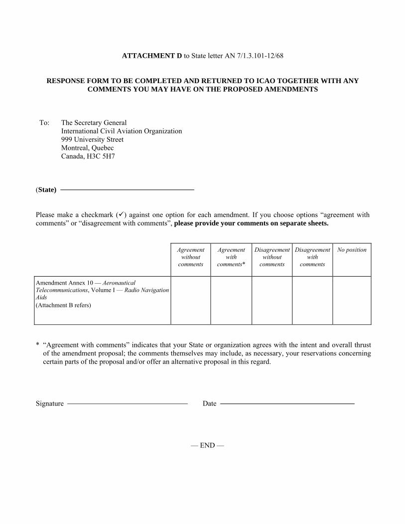
ATTACHMENT D to State letter AN 7/1.3.101-12/68
RESPONSE FORM TO BE COMPLETED AND RETURNED TO ICAO TOGETHER WITH ANY COMMENTS YOU MAY HAVE ON THE PROPOSED AMENDMENTS
To: The Secretary General
International Civil Aviation Organization 999 University Street Montreal, Quebec Canada, H3C 5H7
(State) Please make a checkmark () against one option for each amendment. If you choose options “agreement with comments” or “disagreement with comments”, please provide your comments on separate sheets.
Agreement without
comments
Agreement with
comments*
Disagreement without
comments
Disagreement with
comments
No position
Amendment Annex 10 — Aeronautical Telecommunications, Volume I — Radio Navigation Aids (Attachment B refers)
* “Agreement with comments” indicates that your State or organization agrees with the intent and overall thrust
of the amendment proposal; the comments themselves may include, as necessary, your reservations concerning certain parts of the proposal and/or offer an alternative proposal in this regard.
Signature Date
— END —