Embed Size (px)
Citation preview

Sultan Sonar Manual Rev 1.0
A Higher Level of Performance
www.hawkmeasure.comFor more information, please visit >
G1Microwave Switch SeriesBeam Blockage DetectionCircular Polarisation
Manual

Table of ContentsG1 Microwave Switch Series
2
Contents
Overview 3
Principle of Operation 3Typical Uses 3Function 3Features 3Primary Areas of Application 3
System Components / Dimensions 4
G1 Integral System 4Dimensions 4
Dimensions 5
Mounting Accessories 5MD Series Weldments and Windows 6Waveguides and Waveguide Accessories 7Waveguides and Waveguide Accessories 8
Wiring & Indication 9
System Connection 9
Functionality Layout 10
Relay Functions 11
Test Switch Functions 12
G1R Receiver Test Switch Functions 12
Cross-Talk Prevention 13
Cross-Talk Prevention - Integral Systems 13Wiring 13System Calibration 13
Mounting / Installation 14
Weldment / Couplings and Windows 14Waveguides 15Mounting Example 15General Requirements 16
Setup Procedure 17
Typical Setup 19
Modbus / Troubleshooting 20
Modbus Registers 20Troubleshooting 20
Part Numbers 21
G1 Series 21MA Series Mounting Accessories 21Waveguides & Waveguide Accessories 21Microwave Sequencer 21MD Series Mounting Accessories - Kit 22MD Series Mounting Accessories - Parts 22
Specifications 23
PROPRIETARY NOTICEThe information contained in this publication is derived in part from proprietary and patent data. This information has been prepared for the express purpose of assisting operating and maintenance personnel in the efficient use of the instrument described herein. Publication of this information does not convey any rights to use or reproduce it, or to use for any purpose other than in connection with the installation, operation and maintenance of the equipment described herein
WARNINGThis instrument contains electronic components that are susceptible to damage by static electricity. Proper handling procedures must be observed during the removal, installation, or handling of internal circuit boards or devices:
Handling Procedure:
1. Power to unit must be removed prior to commencement of any work.
2. Personnel must be grounded, via wrist strap or other safe, suitable means, before any printed circuit board or other internal devices are installed, removed or adjusted.
3. Printed circuit boards must be transported in a conductive bag or other conductive container. Boards must not be removed from protective container until the immediate time of installation. Removed boards must be placed immediately in a protective container for transport, storage, or return to factory.

Overview
3
Principle of Operation
A high power circular polarized Microwave pulse is emitted from the Sending unit to the Receiving unit in a transmission chain of approximately 100 pulses per second.
If the path between the Sender and Receiver is blocked by any object or material which absorbs or reflects microwave energy the Receiving unit will no longer detect the complete transmission chain and indicate via Relay for automatic indication and process control requirements.
• State of the art circular polarisation
• Simple sensitivity adjustment and calibration
• IECEx ta tb IIIC T* Da Db
• Theoretical ranges up to 300m (984 ft)
• Simple ‘1-minute’ setup application pre-sets
• Relay outputs: Integral (1 + failsafe)
• Remote test function
• Adjustable ON and OFF delays (0-20 sec)
• Remote 3G Hawklink connection option
• Bright visual status indication on sensors • Independent housing alignment after mounting sensor.
Features
G1 Microwave Switch Series
Function
The Gladiator Microwave Switch can be used for blockage detection, barrier detection, machine detection, collision detection or protection and point level measurement, and detection of objects or material between two points.
Typical Uses
• Blocked chute detection
• Nucleonic switch replacement
• High level alarm / Low level alarm
• Truck / machine detection.
Primary Areas of Application
• Asphalt
• Brewing
• Cement
• Chemical
• Dairy
• Edible oil
• Fertilizer
• Food & Beverage
• Glass
• Mining & Metals
• Oil & Gas
• Packaging
• Paint
• Paper
• Pharmaceutical
• Plastics
• Power Generation
• Refining
• Semiconductor
• Sugar
• Textile
• Water & Wastewater.
*Consult Safety Instructions

System Components / Dimensions
4
G1 Microwave Switch Series
G1 Integral System
The G1 Integral System consists of 2 units. One Sender (G1S) and one Receiver (G1R)
G1S
85mm (3.3")
175
mm
(6.9
")
89m
m (3
.5")
27mm (1.1")
11m
m
(0.4
")
47.
6mm
(1.8
")
1” NPT or BSP
M20
Dimensions
G1S / G1R
G1R

5
Mounting Accessories
DimensionsG1 Microwave Switch Series
39m
m (1
.53”
)
38mm (1.5”)
28 (1
.1”)
1" BSP external thread
46mm (1.81”)
54m
m (2
.13”
)
15mm(0.59”)
68
mm
(2.6
8”)
21mm (0.82”)
1" BSP internal thread
28mm(1.1”)
2" BSP internal thread
2" BSP external thread
1" BSP/NPTinternal thread
68
mm
(2.6
8”)
46mm (1.81”)
39m
m (1
.53”
)
38mm (1.5”)
Vessel /
MA1(Consists of MA1-WC and MA1-UW)
MA1-WCWeldment / Coupling
MA1-UWUHMW Window
39m
m (1
.53”
)
38mm (1.5”)
28 (1
.1”)
1" BSP external thread
46mm (1.81”)
54m
m (2
.13”
)
15mm(0.59”)
68
mm
(2.6
8”)
21mm (0.82”)
1" BSP internal thread
28mm(1.1”)
2" BSP internal thread
2" BSP external thread
1" BSP/NPTinternal thread
68
mm
(2.6
8”)
46mm (1.81”) 39
mm
(1.5
3”)
38mm (1.5”)
Vessel /
MA2(Consists of MA1-WC and MA1-UW)
MA2-WCWeldment / Coupling
MA2-UWUHMW Window

DimensionsG1 Microwave Switch Series
6
MD Series Weldments and Windows
Weldment with UHMW or PTFE Windows
The Weldment is welded to the vessel. The Window locks into the weldment using a locking ring.
For Approval Option 2D Installations. Consult Safety Instructions for critical details.
Weldment
A B
C
D
E
P.C
.D.
10°
N x M5 x 6.5mm (0.25”)
22mm (0.87”)
5mm (0.2”)
19mm (0.75”)
F
HG
UHMW / PTFE Window AssembledPiece
Part No1. Window Material
A B C D E P.C.D No. Holes
mm in mm in mm in mm in mm in mm in
MD1-X UHMW 75 3.0 48 1.9 29 1.1 68 2.7 43 1.7 52 2.0 4
MD2-X UHMW 100 3.9 73 2.9 54 2.1 93 3.7 68 2.7 77 3.0 4
MD3-X UHMW 122 4.8 93 3.7 77 3.0 115 4.5 90 3.5 99 3.9 4
MD6-X PTFE 122 4.8 93 3.7 77 3.0 115 4.5 90 3.5 99 3.9 4
1X = Weldment Material Selection
Part No1. Window Materia
F G H P.C.D No. Holes
mm in mm in mm in mm in
MD1-X UHMW 43 1.7 28 1.1 4 1.6 52 2.0 4
MD2-X UHMW 68 2.7 53 2.1 4 1.6 77 3.0 4
MD3-X UHMW 89 3.5 76 3.0 4 1.6 99 3.9 4
MD6-X PTFE 89 3.5 76 3.0 4 1.6 99 3.9 4
1X = Weldment Material Selection

DimensionsG1 Microwave Switch Series
7
45
40
18
30
1" BSP 3/4" BSP
25
150Min.
150
Min
.
25
3/4" BSP
26.6
47.8
102
3/4" BSP
L=
Cus
tom
er s
peci
fied
30
30
3/4" BSP on either ends
54
15
60
72.
7 2" BSP
60
30
9.6
88.2
6
3" BSP INT THD
4" NPT EXT THD
175
110
37
3/4" BSP
3" BSP 88
3/4" BSP INT
30
35
39
5
3/4" BSP
34
195
130
3/4" BSP
4" NPTTHD
30
MA-WG-03
45
40
18
30
1" BSP 3/4" BSP
25
150Min.
150
Min
.
25
3/4" BSP
26.6
47.8
102
3/4" BSP
L=
Cus
tom
er s
peci
fied
30
30
3/4" BSP on either ends
54
15
60
72.
7 2" BSP
60
30
9.6
88.2
6
3" BSP INT THD
4" NPT EXT THD
175
110
37
3/4" BSP
3" BSP 88
3/4" BSP INT
30
35
39
5
3/4" BSP
34
195
130
3/4" BSP
4" NPTTHD
30
MA-WG-04
45
40
18
30
1" BSP 3/4" BSP
25
150Min.
150
Min
.
25
3/4" BSP
26.6
47.8
102
3/4" BSP
L=
Cus
tom
er s
peci
fied
30
30
3/4" BSP on either ends
54
15
60
72.
7 2" BSP
60
30
9.6
88.2
6
3" BSP INT THD
4" NPT EXT THD
175
110
37
3/4" BSP
3" BSP 88
3/4" BSP INT
30
35
39
5
3/4" BSP34
195
130
3/4" BSP
4" NPTTHD
30
MA-WG-04 with MA-WG14
45
40
18
30
1" BSP 3/4" BSP
25
150Min.
150
Min
.
25
3/4" BSP
26.6
47.8
102
3/4" BSP
L=
Cus
tom
er s
peci
fied
30
30
3/4" BSP on either ends
54
15
60
72.
7 2" BSP
60
30
9.6
88.2
6
3" BSP INT THD
4" NPT EXT THD
175
110
37
3/4" BSP
3" BSP 88
3/4" BSP INT
30
35
39
5
3/4" BSP
34
195
130
3/4" BSP
4" NPTTHD
30
MA-WG-01
Waveguides and Waveguide Accessories

DimensionsG1 Microwave Switch Series
8
45
40
18
30
1" BSP 3/4" BSP
25
150Min.
150
Min
.
25
3/4" BSP
26.6
47.8
102
3/4" BSP
L=
Cus
tom
er s
peci
fied
30
30
3/4" BSP on either ends
54
15
60
72.
7 2" BSP
60
30
9.6
88.2
6
3" BSP INT THD
4" NPT EXT THD 1
75
110
37
3/4" BSP
3" BSP 88
3/4" BSP INT
30
35
39
5
3/4" BSP
34
195
130
3/4" BSP
4" NPTTHD
30
MA-WG12
45
40
18
30
1" BSP 3/4" BSP
25
150Min.
150
Min
.
25
3/4" BSP
26.6
47.8
102
3/4" BSP
L=
Cus
tom
er s
peci
fied
30
30
3/4" BSP on either ends
54
15
60
72.
7 2" BSP
60
30
9.6
88.2
6
3" BSP INT THD
4" NPT EXT THD
175
110
37
3/4" BSP
3" BSP 88
3/4" BSP INT
30
35
39
5
3/4" BSP
34
195
130
3/4" BSP
4" NPTTHD
30
MA-WG12-L=xxx
45
40
18
30
1" BSP 3/4" BSP
25
150Min.
150
Min
.
25
3/4" BSP
26.6
47.8
102
3/4" BSP
L=
Cus
tom
er s
peci
fied
30
30
3/4" BSP on either ends
54
15
60
72.
7 2" BSP
60
30
9.6
88.2
6
3" BSP INT THD
4" NPT EXT THD
175
110
37
3/4" BSP
3" BSP 88
3/4" BSP INT
30
35
39
5
3/4" BSP
34
195
130
3/4" BSP
4" NPTTHD
30
MA-WG-02
45
40
18
30
1" BSP 3/4" BSP
25
150Min.
150
Min
.
25
3/4" BSP
26.6
47.8
102
3/4" BSP
L=
Cus
tom
er s
peci
fied
30
30
3/4" BSP on either ends
54
15
60
72.
7 2" BSP
60
30
9.6
88.2
6
3" BSP INT THD
4" NPT EXT THD
175
110
37
3/4" BSP
3" BSP 88
3/4" BSP INT
30
35
39
5
3/4" BSP
34
195
130
3/4" BSP
4" NPTTHD
30
MA-WG-13
MA-WG11
Waveguides and Waveguide Accessories

Wiring & Indication
9
G1 Microwave Switch Series
****
DelayFSHHI
LO FSL
CAL TEST
OFF OFFSignal
Sens
itiv
ity
microwave senderSTATUS
ON
1 2
ON
1 2
DelayFSHHI
LO FSL
CAL TEST
OFF OFFSignal
Sens
itiv
ity
1 2 3 4 5 6 7 8 9 10
ON
1 2
ON
1 2
3
45 6
7
9
microwave senderSTATUS
1
2
10
8
remote
Signal
STATUS3
4
1 2 3 4 5 6 7 8 9 10 1 2 3 4 5 6 7 8 9 10
1 2 3 4 5 6 7 8 9 10
1 2 3 4 5 6 7 8 9 10
G1S Sender G1R Integral Receiver
Sender
Status LEDGreen when poweredBlinks while working correctlySolid while not transmitting
TEST buttonPress and hold to test level relay action
Receiver
Status LED Green when poweredHigh illumination = strong signalLow illumination = weak signal
Signal ContactSignal can be read with voltmeter across Signal contact point and earth screw (or other ground reference)2.4-2.5V is full signal. 0V is no signal
Use long nose pliers to
extract terminals
1. 2. 3.
DC-IN
+7.
8.
N9.
L110
.
5. 6.
-
SENDER TERMINAL LAYOUT
4.
AC-IN
12-30VDC 80-260VACTerminals 1, 2, 3, 4, 5, 6 not used
RELAY
1.
NC
2.
COM
3.
NO
COMMS DC-IN AC-IN
4.
Test +
7.
8.
N9.
L110
.
5.
B
6.
A -
RECEIVER TERMINAL LAYOUT
12-30VDC 80-260VACRS 485ModbusD0 D1
**If using AC power the earth/ground cable must be connected to the internal ground screw, and the external ground screw must be connected to metallic vessel or earth
System Connection

Functionality LayoutG1 Microwave Switch Series
10
G1S Sender G1R Receiver
(1) Sender status LED• Blinks while working correctly. • Solid while not transmitting.
(2) TEST button• Press and hold to test level relay action.
(3) Sensitivity dial• Turn clockwise for switching in clean environments and object detection. • Turn counter-clockwise for difficult applications, dusty/ wet environments.
(4) Hi / Lo switch• Hi mode for clean environments and object detection. • Lo mode for difficult applications, dusty/wet environments.
(5) FSH / FSL switch• FSH relay normally closed. • FSL relay normally open.
(6) Receiver status LEDs • Green - High illumination for good signal, Low illumination for weak signal.• Red - Relay indication. Illuminated when closed.• Blue - Cal mount indication - flashes during Cal mount, will stay illuminated if Cal mount fails.
(7) Cal Mount switch• Cal mount conducts the automatic setup routine for the system. Perform Cal mount for all new installations, and after adjusting either Sensitivity pot or Hi/Lo switch.• Switch up to initiate Cal mount, wait several seconds, then switch back down. Unit will automatically complete Cal mount routine.
(8) Test switch• Can be used for a failsafe / test relay.
(9) Delay pot• Rotate clockwise to increase Relay on/off delay time.
(10) Signal contact• Signal can be read with voltmeter across Signal contact point and earth screw (or other ground reference). 2.4-2.5V is full signal. 0V is no signal.
Delay2.5 Sec
0.5 Sec
15 Sec
****
DelayFSHHI
LO FSL
CAL TEST
OFF OFFSignal
Sens
itiv
ity
microwave senderSTATUS
ON
1 2
ON
1 2
DelayFSHHI
LO FSL
CAL TEST
OFF OFFSignal
Sens
itiv
ity
1 2 3 4 5 6 7 8 9 10
ON
1 2
ON
1 2
3
45 6
7
9
microwave senderSTATUS
1
2
10
8
remote
Signal
STATUS3
4
1 2 3 4 5 6 7 8 9 10 1 2 3 4 5 6 7 8 9 10
1 2 3 4 5 6 7 8 9 10
1 2 3 4 5 6 7 8 9 10
Functionality Layout

Relay FunctionsG1 Microwave Switch Series
11
Relay Functions
1 2 3
1 2 3
1 2 3
1 2 3
1 2 3
1 2 3Clear path
Blocked path
NC NO
NC NO
NC NO
NC NO
NC NO
NC NO
COM COM
COM COM
COM COM
State 1
State 2
G1R terminal numbers
FailSafe LowFSL
FailSafe HighFSH
Relay Status
Red LED Status
Relay Action
Power Failure
25 26 27 25 26 27
Clear path
Blocked path
NC NO
NC NO
NC NO
NC NO
NC NO
NC NO
COM COM
COM COM
COM COM
State 1
State 2
GSA terminal numbers
FailSafe LowFSL
FailSafe HighFSH
Relay Status
Red LED Status
Relay 1 Action
Power Failure
Normal Operation
Maintenance AlarmSpray Active
Failsafe
NC NO
NC NO
NC NO
COM
COM
COM
State 1
State 2
GSA terminal numbers
Relay Status
Red LED Status
Relay 2 Action
Power Failure
25 26 27 25 26 27
25 26 27 25 26 27
28 29 30
28 29 30
28 29 30
Maintnce Chk GainOpt Clng TimeOpt Clng Relay 2 Failsafe
NC NOCOM28 29 30
NC NOCOM28 29 30
NC NOCOM28 29 30
NC NOCOM28 29 30
NC NOCOM28 29 30
NC NOCOM28 29 30
NC NOCOM28 29 30
NC NOCOM28 29 30
NC NOCOM28 29 30
NC NOCOM28 29 30
MirrorsRelay 1
MirrorsRelay 1

Test Switch FunctionsG1 Microwave Switch Series
12
Receiver Terminal Block
PLC / SCADA / DCS Output Test
Test
Test
Coil rating 500mW maxor 50mA max
Test
To switch an external relay
+12-24Vdc
PLCSCADA DCS Input
Pull up
12-24Vdc
max 50mA
To a PLC input
Externally provided test button
!
!
PLC/SCADA/DCS GROUND MUSTCONNECT BACK TO GLADIATORGROUND OR DC ‘-’ TERMINALS
EXTERNAL PUSH BUTTON GROUNDMUST CONNECT BACK TO GLADIATORGROUND OR DC ‘-’ TERMINALS
Relay will turn on duringnormal system operationor off in failed or unpoweredconditions.
Input will detect ‘0’ state during normal systemoperation, or ‘1’ in failed or unpowered conditions.
4
Receiver Terminal Block
4
4
4
Receiver Terminal Block
Receiver Terminal Block
Failsafe Output ModeTest Switch: OFFTest terminal will provide an output which is able to switch an external failsafe relay or PLC/SCADA/DCS input. During normal system operation this terminal will internally switch a solid state (transistor) output to ground (or DC ‘-’). If power fails or an internal system failure occurs, the terminal will act as an open circuit.
G1R Receiver Test Switch Functions
The test terminal has two potential modes of operation.
Test Input ModeTest Switch: ONTest terminal acts as an input for remote testing of the instrument’s switching function. Used to check for malfunction of unit from a remote position, PLC, SCADA etc.
Test Input from PLC/SCADA/DCS Digital Output
Operator Controlled Press To Test

Cross-Talk PreventionG1 Microwave Switch Series
13
Cross-Talk Prevention - Integral Systems
The GMSEQ Microwave sequencer will operate as the pulse control (Master) for up to 4 Integral systems. Each connected Microwave system will operate as a Slave. The Sequencer will pulse control from CH1 to CH2 to CH3 to CH4 then return to CH1.
More than one system can be connected to each channel, note that each system connected to the same channel will be part of the same slave ‘sequence’ in the pulsing.
First, the Sequencer On and Off time (in Quickset menu of Sequencer) must be set to the following values.
• On time – 2000μs • Off time – 2000μs
Wiring
Please note units still require external power source.
com
com
com
com Tx
CH1 CH2 CH3 CH4
Tx Tx Tx
1 2 3 4 5 6 7 8 9 10
Slave System 1
1 2 3 4 5 6 7 8 9 10
To 3rdSystem
To 4thSystem
A 1L+– NB
DC-In AC-InCOMMS
1 2 3 4 5 6 7 8 9 10 11 12 13 14 15
16 17 18 19 20 21 22 23 24 25 26 27 28 29 30
G1S or GMS Sender
G1Q or GMSRQ Receiver
1 2 3 4 5 6 7 8 9 10
Slave System 2
1 2 3 4 5 6 7 8 9 10
G1S or GMS Sender
G1Q or GMSRQ Receiver
GMSEQ Sequencer
System Calibration
To set up the Microwave systems, perform as per below.
1. Complete wiring of all units to be used in the Sequenced network and apply power.
2. Run setup / calibration as per normal installation instructions.

Mounting / InstallationG1 Microwave Switch Series
14
39m
m (1
.53”
)
38mm (1.5”)
28 (1
.1”)
1" BSP external thread
46mm (1.81”)
54m
m (2
.13”
)
15mm(0.59”)
68
mm
(2.6
8”)
21mm (0.82”)
1" BSP internal thread
28mm(1.1”)
2" BSP internal thread
2" BSP external thread
1" BSP/NPTinternal thread
68
mm
(2.6
8”)
46mm (1.81”)
39m
m (1
.53”
)
38mm (1.5”)
Vessel /
39m
m (1
.53”
)
38mm (1.5”)
28 (1
.1”)
1" BSP external thread
46mm (1.81”)
54m
m (2
.13”
)
15mm(0.59”)
68
mm
(2.6
8”)
21mm (0.82”)
1" BSP internal thread
28mm(1.1”)
2" BSP internal thread
2" BSP external thread
1" BSP/NPTinternal thread
68
mm
(2.6
8”)
46mm (1.81”)
39m
m (1
.53”
)
38mm (1.5”)
Vessel /
Weldment / Couplings and Windows
MA2 - 2” Weldment / coupling with UHMW windows
MA1 - 1” Weldment / coupling with UHMW window
Isolated from process with Weldment / Coupling and window
Mount maximum 100mm (4") back from Window
Isolated from process with Weldment / Coupling and window
Mounted to MA2-UW threaded window
39m
m (1
.53”
)
38mm (1.5”)
28 (1
.1”)
1" BSP external thread
46mm (1.81”)
54m
m (2
.13”
)
15mm(0.59”)
68
mm
(2.6
8”)
21mm (0.82”)
1" BSP internal thread
28mm(1.1”)
2" BSP internal thread
2" BSP external thread
1" BSP/NPTinternal thread
68
mm
(2.6
8”)
46mm (1.81”)
39m
m (1
.53”
)
38mm (1.5”)
Vessel / Isolated from process with Weldment / Coupling and window
Mount maximum 100mm (4") back from Window
39m
m (1
.53”
)
38mm (1.5”)
28 (1
.1”)
1" BSP external thread
46mm (1.81”)
54m
m (2
.13”
)
15mm(0.59”)
68
mm
(2.6
8”)
21mm (0.82”)
1" BSP internal thread
28mm(1.1”)
2" BSP internal thread
2" BSP external thread
1" BSP/NPTinternal thread
68
mm
(2.6
8”)
46mm (1.81”)
39m
m (1
.53”
) 38mm (1.5”)
Vessel /
Sensing element within process
Mounted to MA1-WC threaded weldment / coupling
The weldment / couplings are designed to be welded into an appropriately sized hole in the vessel or application wall. A matching UHMW high wear window is then threaded into the weldment / coupling to act as a seal for the application. For Approval Option 2D Installations the Window is secured using a Locking Ring. See MD Series Windows and Weldments for further information.
This typical installation isolates the Microwave hardware from coming into contact with any damaging materials and allows simple maintenance or replacement of units without having to unseal the process / application.
The Microwave transmission will pass directly through plastics to measure the material in the process.

Mounting / InstallationG1 Microwave Switch Series
15
Waveguides
System with Waveguide extensions for remote mounting / signal transmission.
Waveguides can be used for difficult to access areas or to isolate the electronics from high temperature or non-compatible processes.
For further information on Waveguides see G1 Waveguide parts and assembly guide document available at http://wwww.hawkmeasure.com
MA-WG04
MA-WG13
MA-WG111
MA-WG14
MA-WG10-L=xxx*where xxx = length of pipe in mm
G1R or G1S
MA-WG01
MA-WG02
MA-WG10-L=xxx*where xxx = length of pipe in mm
MA-WG112 MA-WG-13MA-WG12 MA-WG-01
G1R or G1S
MA2-WC-SS
Chute wall
G1R or G1S
G1R or G1S
1Displayed drawing includes qty 5 of MA-WG11 locking nut per side
2Displayed drawing includes qty 3 of MA-WG11 locking nut per side
Mounting Example
System with Waveguide extensions with MA2-WC-SS window and weldment/coupling application seal.

Mounting / InstallationG1 Microwave Switch Series
16
General Requirements
1. When looking for a mounting location it is important to locate and mount the interior of the window/sensor face for each unit flush with the vessel wall and where minimal build-up will occur.
For chute type applications the maximum recommended distance between the Sensor and the chute / window is 100mm (4"). Use Waveguides if electronics cannot be mounted to this requirement.
A cavity or tubed mount in the vessel where the sensor is mounted may fill with process material and will result in a ‘plug’ forming in front of the beam path resulting in unwanted false trips or unit performance issues.
2. Microwave energy cannot penetrate through steel linings or other conductive linings. You must cut a viewing hole and use an appropriate windowed weldment.
3. For high vibration applications, it is necessary to isolate the electronics to keep them from long term damage. This is most often accomplished using 2” UHMW or Teflon windowed weldments in the vessel walls, and mounting the Microwave Sender and Receiver to a separate stable structure (I-beam, handrail) to isolate them from vibration.
4. For high temperature applications which exceed specified maximum temperature it is necessary to ensure that the sensors always remain below 65°C/150°F. Use waveguide assemblies to the high temperature area with the electronics in an appropriately rated area.
When mounting to monitor the level of a flowing product such as coal, ore or wood chips, position the microwave path out of the direct product flow stream. If at all possible, go behind the flow stream or well in front of it. This will minimise any possibility of unwanted trips due to abnormal product flow blocking the beam.
When using the system as a proximity switch such as truck detection the mounting arrangement is application dependent and must ensure proper operation even under worst case conditions.
Do not mount with cavity
Mount behind flush Weldment / Coupling with Window
39m
m (1
.53”
)
38mm (1.5”)
28 (1
.1”)
1" BSP external thread
46mm (1.81”)
54m
m (2
.13”
)
15mm(0.59”)
68
mm
(2.6
8”)
21mm (0.82”)
1" BSP internal thread
28mm(1.1”)
2" BSP internal thread
2" BSP external thread
1" BSP/NPTinternal thread
68
mm
(2.6
8”)
46mm (1.81”)
39m
m (1
.53”
)
38mm (1.5”)
Vessel /
39
mm
(1.5
3”)
38mm (1.5”)
28 (1
.1”)
1" BSP external thread
46mm (1.81”)
54m
m (2
.13”
)
15mm(0.59”)
68
mm
(2.6
8”)
21mm (0.82”)
1" BSP internal thread
28mm(1.1”)
2" BSP internal thread
2" BSP external thread
1" BSP/NPTinternal thread
68
mm
(2.6
8”)
46mm (1.81”)
39m
m (1
.53”
)
38mm (1.5”)
Vessel /
39m
m (1
.53”
)
38mm (1.5”)
28 (1
.1”)
1" BSP external thread
46mm (1.81”)
54m
m (2
.13”
)
15mm(0.59”)
68
mm
(2.6
8”)
21mm (0.82”)
1" BSP internal thread
28mm(1.1”)
2" BSP internal thread
2" BSP external thread
1" BSP/NPTinternal thread
68
mm
(2.6
8”)
46mm (1.81”)
39m
m (1
.53”
)
38mm (1.5”)
Vessel /
Mount behind flush Weldment / Coupling with Window
Mount away from main product flow
Maximum distance between Sensor Face and chute: 100mm (4")

Setup ProcedureG1 Microwave Switch Series
17
1. Mount the units according to Mounting Requirements1.1 If units are AC powered ensure proper grounding is connected to ground screw.
2. Powering the unitThe green status LED on the G1S Sender will blink while working correctly or be solid if not working correctly or not transmitting.
The green LED on the G1R Receiver will stay on permanently to indicate that power is on. The intensity of illumination of the light indicates signal strength (high intensity indicates good received signal).
3. Select the required relay action The Relay can switch ‘ON’ (FSL) or ‘OFF’ (FSH as the microwave beam is blocked. Set the relay action selection switch position depending on your requirements. FSH is recommended (ordinarily on/energized, switches off/ DEN during blocked conditions).
4. Select the Sensitivity There are two adjustments controlling the sensitivity of the switch point:
4.1 The ‘HI/LO’ sensitivity switch is used as the primary sensitivity setting. Select LO sensitivity for Blocked Chute detection and if build-up is expected over sensors. Select HI sensitivity for clean environments,object detection and lighter/less absorptive material or targets. LO recommended for most applications.
4.2 The Sensitivity DialTurning the pot fully counter-clockwise factory recommended for blocked chute applications. If operating in HI mode set the pot to 12 o’clock. In this mode you can turning the pot clockwise to reduce the amount of beam blockage required for switching and vice versa.
Setup Procedure
microwave senderSTATUS
DelayFSHHI
LO FSL
CAL TEST
OFF OFF
Sens
itiv
ity
ON
1 2
ON
1 2
DelayFSHHI
LO FSL
CAL TEST
OFF OFF
Sens
itiv
ity
ON
1 2
ON
1 2
DelayFSHHI
LO FSL
CAL TEST
OFF OFF
Sens
itiv
ity
ON
1 2
ON
1 2
DelayFSHHI
LO FSL
CAL TEST
OFF OFF
Sens
itiv
ity
ON
1 2
ON
1 2
DelayFSHHI
LO FSL
CAL TEST
OFF OFF
Sens
itiv
ity
ON
1 2
ON
1 2
G1S Sender
G1R Receiver
Sensitivity Dial
Sensitivity Switch
Relay Action Switch

Setup ProcedureG1 Microwave Switch Series
18
5. Select the relay time delay
Full anti clockwise is minimum (0.1 seconds). Full clockwise is maximum (20 seconds). Adjust as required allowing time to avoid possible nuisance trips. The selected delay will be used for both an ON delay and an OFF delay.
6. Perform a CAL mount
Do not proceed with this step unless there is clear path between the Sender and Receiver.
Switch CAL switch on the Receiver unit to ON position. The Blue LED will blink to indicate that mounting calibration is now in progress. Wait 5 seconds, then switch the mounting calibration switch to ‘OFF’ position.
The blue LED will switch off after successful calibration. If it stays on this indicates there was a calibration error. If this is the case please check that the path between sender and receiver is clear and alignment is correct. You may need to lower the Sensitivity setting. Try the calibration again. If mounting calibration was successful the blue LED should be off and the Green LED should be ON.
7. Relay test
If required block the Sender with a sample of the application material (note the units are capable of penetrating significant amounts build up). The green LED will dim when the Microwave beam begins to be blocked.
You can also press the ‘TEST’ button on the Sender to simulate the switch condition and trigger the relay action.
Setup Procedure
microwave senderSTATUS
DelayFSHHI
LO FSL
CAL TEST
OFF OFF
Sens
itivity
ON
1 2
ON
1 2
DelayFSHHI
LO FSL
CAL TEST
OFF OFF
Sens
itiv
ity
ON
1 2
ON
1 2
DelayFSHHI
LO FSL
CAL TEST
OFF OFF
Sens
itiv
ity
ON
1 2
ON
1 2
DelayFSHHI
LO FSL
CAL TEST
OFF OFF
Sens
itiv
ity
ON
1 2
ON
1 2
DelayFSHHI
LO FSL
CAL TEST
OFF OFF
Sens
itiv
ity
ON
1 2
ON
1 2
G1R Receiver
Delay PotCal Mount Switch
microwave senderSTATUS
DelayFSHHI
LO FSL
CAL TEST
OFF OFF
Sens
itiv
ity
ON
1 2
ON
1 2
DelayFSHHI
LO FSL
CAL TEST
OFF OFF
Sens
itiv
ity
ON
1 2
ON
1 2
DelayFSHHI
LO FSL
CAL TEST
OFF OFF
Sens
itiv
ity
ON
1 2
ON
1 2
DelayFSHHI
LO FSL
CAL TEST
OFF OFF
Sens
itiv
ity
ON
1 2
ON
1 2
DelayFSHHI
LO FSL
CAL TEST
OFF OFF
Sens
itiv
ity
ON
1 2
ON
1 2
G1S Sender
Relay Test Button
Delay2.5 Sec
0.5 Sec
15 Sec

Typical SetupG1 Microwave Switch Series
19
Typical Setups
Application SetupChute Switch
Chute Switch (dirty conditions)
Vehicle / Machine detection
Presence / Absence switch (clean environment)
Presence / Absence switch (dirty environment)
microwave senderSTATUS
DelayFSHHI
LO FSL
CAL TEST
OFF OFF
Sens
itivity
ON
1 2
ON
1 2DelayFSHHI
LO FSL
CAL TEST
OFF OFF
Sens
itiv
ity
ON
1 2
ON
1 2
DelayFSHHI
LO FSL
CAL TEST
OFF OFF
Sens
itiv
ity
ON
1 2
ON
1 2
DelayFSHHI
LO FSL
CAL TEST
OFF OFF
Sens
itiv
ity
ON
1 2
ON
1 2
DelayFSHHI
LO FSL
CAL TEST
OFF OFF
Sens
itiv
ity
ON
1 2
ON
1 2
microwave senderSTATUS
DelayFSHHI
LO FSL
CAL TEST
OFF OFF
Sens
itiv
ity
ON
1 2
ON
1 2
DelayFSHHI
LO FSL
CAL TEST
OFF OFF
Sens
itiv
ity
ON
1 2
ON
1 2
DelayFSHHI
LO FSL
CAL TEST
OFF OFF
Sens
itiv
ity
ON
1 2
ON
1 2
DelayFSHHI
LO FSL
CAL TEST
OFF OFF
Sens
itiv
ity
ON
1 2
ON
1 2
DelayFSHHI
LO FSL
CAL TEST
OFF OFF
Sens
itiv
ity
ON
1 2
ON
1 2
microwave senderSTATUS
DelayFSHHI
LO FSL
CAL TEST
OFF OFF
Sens
itiv
ity
ON
1 2
ON
1 2
DelayFSHHI
LO FSL
CAL TEST
OFF OFFSe
nsitiv
ity
ON
1 2
ON
1 2
DelayFSHHI
LO FSL
CAL TEST
OFF OFF
Sens
itiv
ity
ON
1 2
ON
1 2
DelayFSHHI
LO FSL
CAL TEST
OFF OFF
Sens
itiv
ity
ON
1 2
ON
1 2
DelayFSHHI
LO FSL
CAL TEST
OFF OFF
Sens
itiv
ity
ON
1 2
ON
1 2
microwave senderSTATUS
DelayFSHHI
LO FSL
CAL TEST
OFF OFF
Sens
itiv
ity
ON
1 2
ON
1 2
DelayFSHHI
LO FSL
CAL TEST
OFF OFF
Sens
itiv
ity
ON
1 2
ON
1 2
DelayFSHHI
LO FSL
CAL TEST
OFF OFF
Sens
itiv
ity
ON
1 2
ON
1 2
DelayFSHHI
LO FSL
CAL TEST
OFF OFF
Sens
itiv
ity
ON
1 2
ON
1 2
DelayFSHHI
LO FSL
CAL TEST
OFF OFF
Sens
itiv
ity
ON
1 2
ON
1 2
Sensitivity Pot: 12 o'clock
Sensitivity Switch: Lo
Delay Pot: 9 o'clock
Sensitivity Pot: Fully counter-clockwise
Sensitivity Switch: Lo
Delay Pot: 9 o'clock
Sensitivity Pot: 9 o'clock
Sensitivity Switch: Hi
Delay Pot: 8 o'clock
Sensitivity Pot: 9 o'clock
Sensitivity Switch: Hi
Delay Pot: 8 o'clock
Sensitivity Pot: 12 o'clock
Sensitivity Switch: Lo
Delay Pot: 9 o'clock
Modbus / TroubleshootingG1 Microwave Switch Series
20
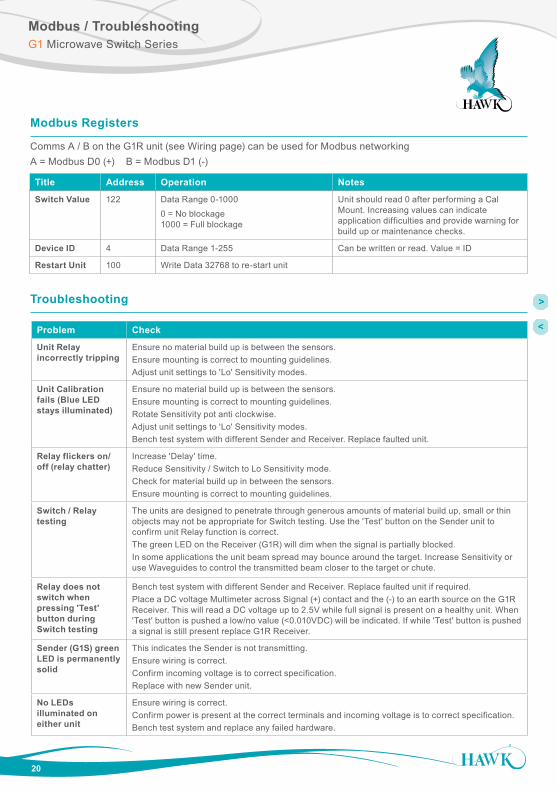
Modbus Registers
Comms A / B on the G1R unit (see Wiring page) can be used for Modbus networkingA = Modbus D0 (+) B = Modbus D1 (-)
Title Address Operation Notes
Switch Value 122 Data Range 0-1000
0 = No blockage 1000 = Full blockage
Unit should read 0 after performing a Cal Mount. Increasing values can indicate application difficulties and provide warning for build up or maintenance checks.
Device ID 4 Data Range 1-255 Can be written or read. Value = ID
Restart Unit 100 Write Data 32768 to re-start unit
Troubleshooting
Problem Check
Unit Relay incorrectly tripping
Ensure no material build up is between the sensors.Ensure mounting is correct to mounting guidelines.Adjust unit settings to 'Lo' Sensitivity modes.
Unit Calibration fails (Blue LED stays illuminated)
Ensure no material build up is between the sensors.Ensure mounting is correct to mounting guidelines.Rotate Sensitivity pot anti clockwise.Adjust unit settings to 'Lo' Sensitivity modes.Bench test system with different Sender and Receiver. Replace faulted unit.
Relay flickers on/off (relay chatter)
Increase 'Delay' time.Reduce Sensitivity / Switch to Lo Sensitivity mode.Check for material build up in between the sensors.Ensure mounting is correct to mounting guidelines.
Switch / Relay testing
The units are designed to penetrate through generous amounts of material build up, small or thin objects may not be appropriate for Switch testing. Use the 'Test' button on the Sender unit to confirm unit Relay function is correct.The green LED on the Receiver (G1R) will dim when the signal is partially blocked.In some applications the unit beam spread may bounce around the target. Increase Sensitivity or use Waveguides to control the transmitted beam closer to the target or chute.
Relay does not switch when pressing 'Test' button during Switch testing
Bench test system with different Sender and Receiver. Replace faulted unit if required.Place a DC voltage Multimeter across Signal (+) contact and the (-) to an earth source on the G1R Receiver. This will read a DC voltage up to 2.5V while full signal is present on a healthy unit. When 'Test' button is pushed a low/no value (<0.010VDC) will be indicated. If while 'Test' button is pushed a signal is still present replace G1R Receiver.
Sender (G1S) green LED is permanently solid
This indicates the Sender is not transmitting.Ensure wiring is correct.Confirm incoming voltage is to correct specification.Replace with new Sender unit.
No LEDs illuminated on either unit
Ensure wiring is correct.Confirm power is present at the correct terminals and incoming voltage is to correct specification.Bench test system and replace any failed hardware.

21
Part NumbersG1 Microwave Switch Series
G1 Series
ModelG1S Gladiator 1” Microwave Integral Sender G1R Gladiator 1” Microwave Integral Receiver, 1 Relay with FailsafeG1Q Gladiator 1” Microwave Integral Sequenced Receiver, 1 Relay with Failsafe (Requires GMSEQ Sequencer) Electronics Housing (Sensor element is 316L with Teflon face) S Powder Coated Aluminum C 316L Stainless Steel Power Supply B 12-30VDC U 12-30VDC and 80-260VAC Mounting Thread TB 1” BSP TN 1” NPT Approvals X Not Required A22 ATEX Grp II Cat 3 GD T85°C IP67 Tamb -40°C to 70°C 2D IECEx ta tb IIIC T* Da Db Tamb = -30 to +80C
G1S C B TB X
MA 1 1” UHMW Window & mild steel weldment/coupling each 1-SS 1” UHMW Window & 316L stainless steel weldment/coupling each 1-UW 1” UHMW Window each 1-WC 1” mild steel weldment/coupling each 1-WC-SS 1” 316L stainless steel weldment/coupling each 2 2” UHMW Window & mild steel weldment/coupling each 2-SS 2” UHMW Window & 316L stainless steel weldment/coupling each 2-UW 2” UHMW Window each 2-WC 2” mild steel weldment/coupling each 2-WC-SS 2” 316L stainless steel weldment/coupling each
MA 2 Additional mounting accessory variants and materials including high temperature ceramics are available. See Gladiator Gen 3 Microwave datasheet available at www.hawkmeasure.com
MA Series Mounting Accessories
MA-WG 01 316L Threaded connector for Sender / Receiver 02 316L 90deg bend pipe (150mm + 150mm). Includes qty 2 of MA-WG11 03 316L 1-1/2” Wave guide horn. Includes Qty 1 MA-WG13 04 316L 3” Wave guide horn. Includes Qty 1 MA-WG13 10-L=1 316L Straight pipe extension 1L= length in mm. Includes qty 2 of MA-WG11 11 316L Locking nut 12 2” BSP Teflon plug with socket to match MA-WG03 horn 13 316L Pipe to pipe connector coupling 14 4” Teflon window to match MA-WG04 Horn. Fits into MA18 weldment
MA-WG 01
Waveguides & Waveguide Accessories
GMSEQ Gladiator Microwave Sequencer Power Supply B 12-30VDC C 30-48VDC and 48-90VAC U 12-30VDC and 90-260VAC
GMSEQ U
Microwave Sequencer

22
Part NumbersG1 Microwave Switch Series
For Approval Option 2D Installations. Consult Safety Instructions for critical details.
MD Mounting Accessories Kit
Window Facing Material
1 1” UHMW Window (-30°C to +75°C) 2 2” UHMW Window (-30°C to +75°C) 3 3” UHMW Window (-30°C to +75°C) 6 3” PTFE Window (-30°C to +200°C) -
Weldment Material
A SS304 S SS316 M Mild Steel
MD 3 - A
MD Series Mounting Accessories - Kit
For Approval Option 2D Installations. Consult Safety Instructions for critical details.
BASE Weldment Only - Weldment Size
MD1 Matches MD1 MD2 Matches MD2 MD3 Matches MD3 & MD6 - Material
A SS304 S SS316 M Mild Steel
BASE - MD2 - A
WIN Window only
-
Window Facing Material
MD1 UHMW for MD1 (-30°C to +75°C) MD2 UHMW for MD2 (-30°C to +75°C) MD3 UHMW for MD3 (-30°C to +75°C) MD6 PTFE for MD6 (-30°C to +200°C)
WIN - MD2
MD Series Mounting Accessories - Parts
LRING Locking Ring Only - Ring Size
MD1 Matches MD1 MD2 Matches MD2 MD3 Matches MD3 & MD6 - Material
A SS304 S SS316 M Mild Steel
LRING - MD2 - A
MD Series Part Combinatinos
Full Kit1 Size Window Weldment1 Locking Ring1
MD1-X 1” WIN-MD1 BASE-MD1-X LRING-MD1-X
MD2-X 2” WIN-MD2 BASE-MD2-X LRING-MD2-X
MD3-X 3” WIN-MD3 BASE-MD3-X LRING-MD3-X
MD6-X 3” WIN-MD6 BASE-MD3-X LRING-MD3-X
1X = Material Selection

SpecificationsG1 Microwave Switch Series
23
Operating Voltage
• 12-30VDC (residual ripple no greater than 100mV) • 80-260VAC.
Power Consumption
• <0.8W @ 24VDC • <5VA @ 240VAC • <3VA @ 115VAC.
Communications
• GosHawk, Modbus • Multidrop mode can address 1-250 units over 4 wires.
Relay Output
• Form ‘C’ (SPDT) contacts, rated 5A at 240Vac resistive • Remote fail-safe test facility for one relay.
Operating Temperature
• Integral Units -30°C (-20°F) to 65°C (150°F)*. *For higher temperature applications, remote waveguide mounting with appropriate windows is necessary.
Power Density
• Rated from emitter to receiver at approximately 20µW/cm² • Complies with FCC Title Rules Part 15 (Beam Blockage) • Caution sign posting not required.
Transmitted Signal
• Circular polarisation polarity • Frequency: 10.525GHz • Power: +14dBm / 25mW • Sensitivity -88dBm • Beam width 50º
Fail-Safe
• Selectable - presence or absence of material • High level fail-safe: relay is activated when material is present. • Low level fail-safe: relay is activated when no material is present.
Range
• Theoretical maximum range: 300m (984 ft) • Recommended range (chutes) 15m • Recommended range (object detection) 50m • Minimum range under ideal conditions: 10cm (4 inches). Note: Minimum ranges are dependent on application conductivity.
Maximum Operating Pressure
• 2 BAR.
Enclosure Sealing
• IP66/67.
Wetted Materials
• Sensing element housing: 316L stainless steel • Sensing element face: Teflon.
Cable Entries
• Integral Units: 2 x M20 Glands / 3/4” NPTF threaded adapters.
Mounting
• 1” NTP • 1” BSP.
Remote Test Input
• Press to test (used to check for malfunction of unit from remote position, PLC, SCADA etc).
Weight
• G1R 1kg • G1S 1kg.
Approval
• IECEx Zone 20/21, Zone 21 • Ex ta tb IIIC T* Da Db Tamb = -30 to +80C • IP66
Specifications model dependent
*Consult Safety Instructions

A Higher Level of PerformanceG1 Microwave Switch Series
All company or product names are registered trademarks or trademarks of their respective owners.
Hawk Measurement Systems(HeadOffice)15 - 17 Maurice Court Nunawading VIC 3131, AUSTRALIA
Phone: +61 3 9873 4750Fax: +61 3 9873 [email protected]
Hawk Measurement 96 Glenn Street Lawrence, MA 01843, USA
Phone: +1 888 HAWKLEVEL (1-888-429-5538)Phone: +1 978 304 3000Fax: +1 978 304 [email protected]
For more information and global representatives: www.hawkmeasure.com DO
C-G
1MIC
-SW
ITC
H-M
AN
Rev
. 1.3
09
16
HAWK, Since 1988
Hawk Measurement Systems Pty Ltd (HAWK) was established in 1988. It's founding members saw the universal requirement of various industries requiring improved process control and efficiency in their operations.
We Can Help
HAWK understands the difficulties customers face when seeking accurate level measurement. Every application is different, involving a multitude of environmental factors. This is where HAWK excels. Our aim is to ensure that customers not only feel comfortable with our technology, but also to ensure a consistent and reliable solution is in place for the long term. We believe that a combination of application and product expertise, as well as forward thinking and proactive support policies are the foundation of successful customer-supplier relationships.
Progressive Technical Support
HAWK believes that the future of the Level Measurement Industry revolves around the quality of pre and post sales - support. Our aim is for all sales & support staff to be product experts, and more importantly application experts making our customers applications as efficient and consistent as possible.
Remote Innovation
HAWK understands the need for immediate technical assistance.
The HAWKLink 3G communication device allows any computer with internet access and our free GosHawk diagnostic & calibration software; to dial in, calibrate, test, and check the performance of HAWK products. This innovative system allows our Global Support Team to assist with commissioning and after sales service of HAWK equipment worldwide. Measurement problems are addressed as they happen; not days or weeks later.
Knowledge Sharing
HAWK believes that knowledge sharing is key to creating long term relationships. Empowering our customers and our worldwide distribution network, whilst being available at all times to lend a helping hand, is the perfect recipe for long term solutions and relationships. HAWK openly extends an invitation to share our 25 plus years of level measurement experience, and ensure that your day to day processes are efficient, understood, and always working.