Embed Size (px)
Citation preview
ASCO Power Technologies, Florham Park, NJ 07932 1 800-800-ASCO
October 1, 2014 Publication 3135 R5
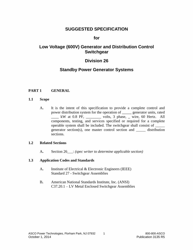
SUGGESTED SPECIFICATION
for
Low Voltage (600V) Generator and Distribution Control Switchgear
Division 26
Standby Power Generator Systems
PART 1 GENERAL
1.1 Scope
A. It is the intent of this specification to provide a complete control and
power distribution system for the operation of _____ generator units, rated
____ kW at 0.8 PF, ________ volts, 3 phase, _ wire, 60 Hertz. All
components, testing, and services specified or required for a complete
operable system shall be included. The switchgear shall consist of _____
generator section(s), one master control section and _____ distribution
sections.
1.2 Related Sections
A. Section 26___: (spec writer to determine applicable section)
1.3 Application Codes and Standards
A. Institute of Electrical & Electronic Engineers (IEEE)
Standard 27 - Switchgear Assemblies
B. American National Standards Institute, Inc. (ANSI)
C37.20.1 – LV Metal Enclosed Switchgear Assemblies
ASCO Power Technologies, Florham Park, NJ 07932 2 800-800-ASCO
October 1, 2014 Publication 3135 R5
C. National Fire Protection Association (NFPA)
NFPA-70 - National Electrical Code
NFPA-99 - Essential Electrical Systems for Health Care Facilities
NFPA-110 - Standard for Emergency and Standby Power Systems
D. Underwriters Laboratories, Inc.
[UL 891 Low Voltage Switchboard]
[UL 1558 Low Voltage Metal Enclosed Switchgear]
Note: Spec writer to determine which UL listing shall be applicable.
E. International Standards Organization
ISO 9001
F. International Building Code (IBC)
California Building Code (CBC)
Equipment, including installed overhead lifting device, shall be
seismic shake table tested in accordance with ICC-ES AC-156 by an
independent and certified seismic qualification agency.
Equipment, including installed overhead lifting device, shall be
certified with Design Spectral Response Acceleration at Short Periods
(SDS) equal to 2.46
1.4 Manufacturer’s Qualifications
Automatic Transfer Switches, Bypass Switches, Paralleling Switchgear,
Switchboards, Station Batteries (if required), and Monitoring & Control shall be
supplied by a single manufacturer.
The equipment described, as a minimum, shall meet all of the requirements
specified in this section. The equipment shall be the product of a manufacturer
who has produced paralleling switchgear for a period of no less than 20 years.
The manufacturer must provide integral electrical and mechanical design,
fabrication and construction services for all cubicle structures, formed and
punched bus bar, and control panel assemblies. Comprehensive documentation
detailing electrical and mechanical designs shall be available upon request.
1.5 Order Management
Management of orders shall be assigned to personnel employed and trained
specifically and exclusively for project management; the use of field service
representatives, design engineers or sales representatives for order management
purposes shall not be acceptable. Each order shall be managed by both a factory-
based project manager and a factory-direct field-based project manager.
1.6 Documentation
ASCO Power Technologies, Florham Park, NJ 07932 3 800-800-ASCO
October 1, 2014 Publication 3135 R5
A. Submittals for approval shall include the following:
1. Elevation drawings with shipping splits identified and estimated
weights.
2. Outline drawings showing conduit entry areas and anchoring
provisions.
3. Single line diagram.
4. Sequence of operation.
5. Bill of material listing items by manufacturer’s name, part number
and description.
6. Complete nameplate and status annunciator panel schedule.
7. Technical literature for major components.
B. Operation and maintenance manuals shall contain:
1. Complete Set of Drawings
2. Detailed Interconnect Spreadsheet
3. Complete Bill of Material
4. Instruction Manuals for Major Components
5. Sequence of Operation
6. Warranty Statement
A quantity of 1 hardcopy and 6 digital manual(s) shall be provided.
1.7 Testing
The equipment shall be fully assembled for factory testing. Testing shall include,
but not be limited to primary injection of the applicable three phase voltage for
potential transformer circuits, and three phase 5A secondary injection testing of
the current circuits. The circuit breakers supplied shall be installed in their
intended positions and electrically and mechanically tested. All cubicles shall be
subjected to a dielectric voltage-withstand test, for 1 minute, at twice the service
voltage plus 1000 volts. A narrative of the system operation shall be provided
and shall be utilized when testing the equipment. A certified factory test report
shall be furnished to verify system testing.
1.8 Warranty and Service
A. Manufacturer shall warrant the equipment for a minimum of eighteen
months from date of shipment subject to terms and conditions of
manufacturer’s current warranty publication.
B. Manufacturer shall have an established network of factory-direct service
technicians capable of servicing the equipment.
ASCO Power Technologies, Florham Park, NJ 07932 4 800-800-ASCO
October 1, 2014 Publication 3135 R5
C. Manufacturer’s field service representatives shall be on call and available
for immediate dispatch 24 hours a day, 365 days a year. All field service
personnel shall be factory trained, by the manufacturer, and certified in the
maintenance and repair of the specified equipment. Manufacturer must
employ a minimum of 2 field service technicians within a 150 mile radius
of the installation site. Field service representatives shall have access to
common replacement components locally and the service organization
shall have a detailed counter-to-counter process for providing emergency
spares 24 hours a day 7 days a week.
D. Post-warranty service contracts shall be made available to the owner by
the manufacturer to provide scheduled maintenance and/or emergency
repair of the equipment.
1.9 General Requirements
A. Switchgear Enclosure
1. Structure. The enclosure shall be free-standing and floor
supported, with front and rear access. An adequate number of
anchor bolt holes shall be designed to place the base in direct
contact with the foundation when bolted. The flatness of the floor
surface upon which the equipment is installed shall deviate no
more than 0.125 inches per 10 feet in any direction. All doors
shall be formed of 11 gauge steel, and be provided with sufficient
hinges to support the door and components. Doors must swing
open more than 90 degrees. Front doors shall be supplied with a
lockable handle. Rear doors shall be supplied on all bussed
sections. All door locks shall be keyed alike, with one key
supplied for each lock. All panel covers shall be formed type, and
secured with screws as necessary.
The sheet steel used for the finished assembly shall be degreased
and thoroughly cleaned through a minimum five stage aqueous
process. The finish shall be ANSI-61, light gray, electrostatically
charged powder paint over a phosphate coating, at an average of
2.0 mils. Finish shall be suitable for indoor and outdoor
environments.
2. Bus. Main bus shall be silver plated copper and have a maximum
current density of no more than 1000 amperes per square inch.
Main bus shall be rated for ______ amperes and have a minimum
bracing level of not less than [ ] 100,000 amperes [ ] 200,000
amperes RMS symmetrical, for a minimum of (4) cycles and must
meet UL 1558 heat rise test.
ASCO Power Technologies, Florham Park, NJ 07932 5 800-800-ASCO
October 1, 2014 Publication 3135 R5
3. Wiring. Control wiring shall be UL 1015 rated for 600 volt.
Current transformer circuit terminations shall be ring tongue type
and include shorting terminal blocks.
Control wires shall be numbered every eight (8) inches or less and
visible next to the terminals. Wiring shall be permanently marked
with wire termination designations. These designations shall
include the device and connection point where the wire is
terminated. All control wire markings shall be printed directly on
the wire insulation and be permanent. Current Transformer wire
shall be 12 gauge.
Low level signal circuits shall be separated and provided with
shielded wire to minimize electromagnetic interference. Shielded
wire shall be grounded at one point. Ethernet cabling shall be
unshielded category 5 or higher.
Wiring between each section shall not be spliced, and shall be free
of abrasions and tool marks. Connections between cubicles shall
use labeled connection plugs. Wires shall be placed in wire duct or
harnessed, and shall be supported to prevent sagging or breakage
from weight or vibration. Inter-cubicle wiring harnesses shall be
contained in overhead steel wire troughs. Communication cables
and current transformer circuits shall be hard wired.
All wiring to hinged doors shall be run through door terminal
blocks or connection plugs. Terminal blocks shall be provided for
all external connections and placed in an accessible area not
exposed to hazardous bus or cables, if possible. Current
transformer circuits shall be connected through shorting terminal
blocks.
4. Nameplates. Engraved laminated plastic nameplates, having black
letters on white background, shall identify major components,
vertical sections, and circuit breakers. Nameplates shall be
attached with self-tapping screws.
5. [Overhead Lifting Device. Equipment shall include an integrated
overhead lifting device. The device shall travel on rails and extend
beyond the front of the switchgear to facilitate the insertion or
removal of a withdrawn power circuit breaker. Seismic
certification of the switchgear, if required, shall include the
overhead lifting device.]
6. Lugs. Lugs shall be 2-hole [compression | mechanical], size,
conductor type and quantity per conductor as shown in drawings.
ASCO Power Technologies, Florham Park, NJ 07932 6 800-800-ASCO
October 1, 2014 Publication 3135 R5
B. Components
1. Synchroscope. Synchroscope shall consist of industrial
switchboard type meters, 4-1/2" square, 1% accuracy.
3. Current Transformers. Current transformers shall be furnished
with VA burden ratings suitable to supply the metering and
protective devices without affecting accuracy.
4. Potential Transformers. Three (3) wye-wye connected potential
transformers shall be provided in turns ratio and VA burden rating
to be compatible with the controls and voltage sensing as applied.
Transformers shall have integrally mounted primary and secondary
fuses.
5. Alarm and Status Indication. Visual and audible alarm and status
indication lights, including spares, shall be furnished as indicated
by customer. Visual alarms shall be reset only after the fault
condition has been corrected. The audible alarm shall include a
silencing circuit which after activation shall permit audible
annunciation of subsequent failures. Lamp test shall be an integral
feature of this indicator. Each illuminated indicator tile shall be 24
mm x 24 mm.
6. Control Fuses. Fuses shall be mounted in locations where they are
readily accessible. Pull-out type fuses shall be provided for all
primary circuits and shall be of the current limiting type.
C. Electromagnetic Control Relays
All electromagnetic control relays shall be suitable and adequately rated
for their intended service in the control system. All relays for control
circuit duty shall be plug-in type with retaining clips and transparent
plastic covers. Relays shall be clearly marked for control voltage. When
possible, all relays shall have light-emitting diodes to indicate that the coil
is energized.
1.10 Acceptable Manufacturer
The equipment described shall be manufactured by ASCO Power Technologies.
Any alternates to this bid shall only be considered if a complete written
description of the proposed system along with any variances to the specification,
are received ten (10) days prior to bid due date. Any variances not specifically
enumerated prior to bidding shall be considered non-responsive. Alternate
manufacturers must be approved in writing by the Engineer as an addendum.
ASCO Power Technologies, Florham Park, NJ 07932 7 800-800-ASCO
October 1, 2014 Publication 3135 R5
Costs incurred to modify the building and/or interfacing equipment which are
affected as a result of an alternate, shall be the responsibility of the contractor.
PART 2 SECTIONS
2.1 Generator Power and Control Section
A. Each generator section shall contain over-current protection, controls,
relays and auxiliary devices associated with its respective engine generator
set. It shall include the following:
For each generator set, a UL 1066 listed low voltage power circuit breaker
shall be furnished to provide over-current protection and paralleling
functions. The breaker shall be ____ AF, ____ AT, 3 pole, electrically
operated, draw-out, with solid state trip unit. Trip unit shall include
adjustable long delay, short delay, and instantaneous trip settings as well
as ground fault alarming. Breakers shall have stored energy closing. The
draw-out feature shall provide for connected, test, and disconnected
positions. In the connected position, the main line and load terminals, all
auxiliary control contacts, and circuitry shall be connected, and the
breaker shall be fully operable. In the test position, the breaker auxiliary
control contacts, and circuitry only shall be connected, to permit automatic
operation of the complete control system without actually connecting the
generator to the main bus. In the disconnect position, main auxiliary
control contacts, and circuitry shall be completely disconnected. The
breaker draw-out mechanism shall be mechanically interlocked with the
breaker to permit draw-out operation only when the breaker main contacts
are open. The circuit breaker shall be provided with _____AIC rating.
(Spec writer to determine interrupt capacity required)
B. Generator Control System
Paralleling controls for each generator shall include a programmable logic
controller and a Woodward DSLC-2 digital synchronizer and load
controller designed for use on three-phase AC generators and mounted in
the switchgear. The controls shall combine a synchronizer (with voltage
matching capability), load sensor, load control, dead bus closing system
interlock, VAR, power factor and process control. The load sharing
network and VAR sharing network shall be completely integrated in the
switchgear.
The controls shall sense true RMS power and provide soft loading and
unloading functions on the main bus.
DC-to-DC converter(s) shall be in each generator control section to
ASCO Power Technologies, Florham Park, NJ 07932 8 800-800-ASCO
October 1, 2014 Publication 3135 R5
provide a constant 24VDC power. The generator section DC-to-DC
converter shall supplement the DC-to-DC converter in the master control
section. Control power shall be sourced from generator set batteries and
sustain adequate control voltage during an engine crank. The converters
shall provide power for up to 75% rated load if the source voltage drops to
12 volts. Source voltage shall not exceed 32 volts.
Generator controls shall include the following functions, components,
devices, and indicators.
1. Reverse Power Protection (Device 32R)
2. Generator Voltage Monitoring and Frequency Monitoring
Generator controls shall monitor voltage and frequency to ensure
the generator is not connected to the bus until frequency is at least
59 Hertz and 90% rated voltage.
3. Automatic Synchronizer
The synchronizer shall include a differential voltage detector,
differential frequency detector and differential phase detector.
Analog voltage bias signal shall be provided for voltage matching
and an analog speed bias signal shall be provided for frequency
matching and phase angle control. Synchronizer shall issue a
breaker close signal when frequency, phase and voltage conditions
are met.
The differential voltage detector shall compare the voltage of the
oncoming generator to the paralleling bus. If the voltage is not
within the factory set difference of plus or minus 5% (adjustable
from 0 to plus or minus 10%), the voltage detector shall inhibit the
circuit breaker from closing. When the oncoming generator
voltage is within the preset acceptable limit, the inhibit shall be
removed.
The differential frequency detector shall compare the frequency of
the oncoming engine generator set to the paralleling bus. If the
frequency is not within the preset acceptable difference of plus or
minus 0.5 Hz (adjustable from 0 to plus or minus 0.5 Hz), the
frequency detector shall inhibit the circuit breaker from closing.
When the oncoming engine generator frequency is within the
acceptable limit, the inhibit shall be removed.
The differential phase detector shall compare the phase angle of
the oncoming engine generator set to the paralleling bus. If the
ASCO Power Technologies, Florham Park, NJ 07932 9 800-800-ASCO
October 1, 2014 Publication 3135 R5
phase angle is not within the preset acceptable difference of plus or
minus 0.05 Hz (adjustable from plus/minus 0.02 to 0.25 Hz), the
phase detector shall inhibit the circuit breaker from closing. When
the oncoming engine generator phase angle is within the
acceptable limit, the inhibit shall be removed.
4. Multiple Circuit Interlock
Generator controls shall provide for first-up, first-on operation of
the generator set. This device shall positively prevent more than
one set from being simultaneously connected to a dead bus. Upon
initiation of the connection of the first set to the bus, this circuit
shall shift the control of the remaining sets to automatic or manual
synchronizing at the operator's discretion.
C. Engine Starting Control
1. The engine starting control shall be in a dedicated programmable
logic controller and shall automatically start, protect, and monitor
each engine generator set. The controller shall be provided with
power supply, CPU and required I/O modules. Engine start control
shall additionally be hard wired so that the engine can be
automatically or manually started if the controller is not available.
The programmable logic controller shall be dedicated for control
exclusively of the engine and generator set and shall be
independent of the Master PLC. Distributed I/O systems which
rely on a master controller shall not be acceptable.
2. Engine Start/Stop Operation
The automatic engine control logic shall initiate operation of the
engine upon receipt of a signal from a contact that closes for
engine run, and opens for engine stop.
3. Five Position Engine Control Selector Switch
Lockout/Reset - When placed in this position, the engine shall not
be capable of starting and/or running. If the engine was shut down
due to the operation of a protective device, the shutdown
malfunction shall be reset when the switch is moved to this
position. If the engine is running when the switch is moved to this
position, it shall immediately shut down.
Off/Cooldown - When placed in this position, the engine shall shut
down after soft unloading from the bus (provided another source is
connected to the bus) and a cool-down period.
ASCO Power Technologies, Florham Park, NJ 07932 10 800-800-ASCO
October 1, 2014 Publication 3135 R5
Automatic - When placed in this position, the engine control shall
be in readiness for fully automatic operation upon receipt of a start
signal.
Test Off-Line - When placed in this position, the engine shall start
and run as if a start signal were received except it shall not be
connected to the bus. If a start signal is received, normal automatic
functions shall resume. When returned to the Automatic position,
the engine shall shut down.
Test On-Line - When placed in this position, the engine shall start,
run, and connect to the bus. When returned to the Automatic
position the circuit breaker shall open, provided no automatic start
signal is present, and the engine shall run for its cool-down period
before shutting down.
4. Four Position Synchronizing Mode Selector Switch
Permissive - In this position the governor controls are deactivated.
However, the synchronizer shall operate as a passive synch check
relay and signal the closing of the generator breaker when both
sources are in phase.
Check - In this position the synchronizer is fully operational except
it cannot close the generator breaker. The phase-lock feature holds
the generator output in synchronism with the bus.
Off - In this position the synchronizer is turned off to allow for
manual paralleling at the Master Cubicle.
Run - In this position the synchronizer is in the fully operational,
automatic mode.
5. Engine Cooldown Time Delay
The cooldown time delay shall be adjustable from 1 to 10 minutes
(factory set at 5 minutes) and automatically bypassed for
malfunction and manual shutdown of the engine generator set.
6. Failure to Synchronize Time Delay
The failure to synchronize time delay shall be fixed at 60 seconds.
It shall provide audible and visual indication, but it shall not
terminate synchronizing attempts nor shut down the engine.
ASCO Power Technologies, Florham Park, NJ 07932 11 800-800-ASCO
October 1, 2014 Publication 3135 R5
D. Alarm and Status Indication
FUNCTION COLOR
LAMP TEST (PUSHBUTTON)
PARALLEL CB OPEN GREEN
PARALLEL CB CLOSED RED
AUTO START GREEN
ENGINE RUNNING GREEN
PLC STOPPED RED
CONTROL VOLTAGE FAILURE RED
CONTROLS NOT IN AUTO RED
POWERQUEST OVERRIDE AMBER
GEN COMMON SHUTDOWN RED
DC CONVERTER FAILURE RED
DSLC-2 SELF TEST FAILED RED
ASCO Power Technologies, Florham Park, NJ 07932 12 800-800-ASCO
October 1, 2014 Publication 3135 R5
E. Generator Control Station
FUNCTION SELECTIONS
GENERATOR CONTROL SWITCH LOCKOUT/RESET
OFF/COOLDOWN
AUTOMATIC
TEST OFFLINE
TEST ONLINE
SYNCHRONIZING MODE SWITCH PERMISSIVE
CHECK
OFF/COOLDOWN
RUN
EMERGENCY STOP PUSHBUTTON -
ALARM RESET PUSHBUTTON -
VOLTAGE CONTROL SWITCH LOWER
OFF
RAISE
SPEED CONTROL LOWER
OFF
RAISE
2.2 Master Control Section
(note: spec writer to select from PLC options below)
The master control section shall contain [a programmable logic controller |
[redundant programmable logic controllers] capable of storing necessary control
sequence algorithms, variable operation set-points, time delays and alarming
levels. Distributed I/O stations shall include modular input and output cards for
discrete and analog signals necessary to provide the integrated system operations
specified below.
A. Priority Load Control
Discrete output modules shall be provided to control the necessary priority
load blocks. The number of load blocks shall equal the number of engine
generator sets, and shall be sized such that the connectable load of each
block is not greater than the kilowatt rating of the generator set connected.
As the generators are connected to the bus, the controller shall signal for
the connection of the load blocks in an ascending sequential priority with
the highest priority load requiring emergency power being connected first.
Priority failure pass-along logic shall initiate the connection of low
priority loads to the first generator on-line if start signals have not been
received from high priority transfer switches or other devices.
Load shedding shall be done on a last-on, first-off basis. The generator
ASCO Power Technologies, Florham Park, NJ 07932 13 800-800-ASCO
October 1, 2014 Publication 3135 R5
bus shall have a solid-state frequency monitor, with integral time delay to
initiate load shedding upon a reduction of bus frequency to 58 Hz or less,
for a period of three seconds or more. Upon sensing a bus
underfrequency, the system shall automatically shed the lowest priority
load connected at the time of occurrence. This shed circuit shall override
any manual load-add operation, and shall lock out the manual load-add
circuitry. It shall give provide and audible alarm annunciation of bus
underfrequency load shed.
Provide means to reset the bus underfrequency signal.
Provide a “load shed bypass/reset” push-button, for manual supervised
operation over the load-shed, load-add control logic. One push-button
shall be provided for each priority block except first priority. Logic shall
be provided in the event that a bus overload occurs resulting in a reduction
in bus frequency; the bypassed priority load shall be shed automatically
through override logic control.
B. Power Management Applications
Master controls applications shall include Load Bus Optimization and
Generator Load Demand
Load Bus Optimization shall control individually prioritized and
separately controlled distribution loads via power transfer switches and/or
electrically operated circuit breakers. Loads shall be added or removed
from a bus segment according to the available headroom on the bus.
Generator Load Demand shall control individually prioritized and
separately controlled engine-generator sets. Engine-generator sets shall be
added or removed from a bus segment according to dynamic
measurements of power consumption and engine-generator efficiency set-
points.
C. Manual Paralleling Controls
A Synchroscope selector switch shall be provided to select any generator
for manual paralleling operation. The positioning of the selector switch
shall simultaneously connect the synch-check relay, Synchroscope, and
“manual paralleling” push-button to the selected generator.
A solid-state sync check relay shall be furnished for manual paralleling, to
sense and compare the phase angle difference between the oncoming
generator and the bus. This relay shall lockout the manual paralleling
push-button until the oncoming generator is within 15 degrees of
synchronism.
ASCO Power Technologies, Florham Park, NJ 07932 14 800-800-ASCO
October 1, 2014 Publication 3135 R5
Operation shall be arranged so the operator shall depress and hold the
manual paralleling push-button. When the relative phase angle reduces to
15 degrees and going towards zero degrees, the sync check relay’s output
contact shall initiate the closing of the respective oncoming generator
breaker.
The manual paralleling interface controls and metering shall be grouped in
a central location on the front of the master control section. This shall
allow for paralleling multiple generators from one location within the
switchgear. Manual paralleling controls and sync check relay shall be
hardwired and shall not rely on touch screens or programmable logic
controllers to perform manual paralleling functions.
D. DC Control Power Selector – Best Battery System
Control power for the system logic shall be derived from the engine
starting batteries and/or an optional station battery system. The control
logic shall be powered through a suitable means that shall permit
continuity of power until the last battery is no longer available. The
controls shall be powered from any battery or combination of batteries and
prevent feedback to a failing battery. The transition of control logic power
from any battery combination to any other battery combination shall be
accomplished without disruption in the power flow.
DC-to-DC converters shall provide a constant 24VDC power to the master
and generator controllers during starting and cranking of all engine
generator sets “simultaneously”.
Additionally, the best battery system shall provide power to each
generator paralleling circuit breaker trip coil if the generator battery power
to its cubicle is lost.
E. System Test Switch
Provide a system no-load test switch to initiate a complete automatic
system operation by simulating the closure of the remote engine start
signal.
ASCO Power Technologies, Florham Park, NJ 07932 15 800-800-ASCO
October 1, 2014 Publication 3135 R5
F. Alarm and Status Indication
FUNCTION COLOR
LAMP TEST (PUSHBUTTON)
EMERGENCY MODE AMBER
I/O COMM FAILURE RED
BUS UNDER FREQUENCY RED
ATS CONTROL FUSE BLOWN RED
PLC 1 STOPPED RED
PLC 2 STOPPED * RED
CONTROL VOLTAGE FAILURE RED
DC CONVERTER FAILURE RED
* Only with redundancy option
G. Main Audible Alarm
Provide a main audible alarm. The alarm horn shall be the DC vibration
type, subsequent malfunctions to resound the alarm if the horn had been
previously silenced.
H. Paralleling Bus Metering / Instrumentation
1. Synchroscope and Synchroscope Plant Selector Switch with
positions for each generator
2. Bus Under/Over-Voltage Relay
3. Bus Under/Over-Frequency Relay
I. Master Control Station
FUNCTION COLOR
BUS ALARM RESET PUSHBUTTON -
ALARM SILENCE PUSHBUTTON RED
MANUAL PARALLEL PUSHBUTTON GREEN
J. Master Controller
The master programmable logic controller shall be programmed by ASCO
and shall meet or exceed the following specifications:
1. GE RX3i with CPU, power supply, I/O, and communications.
2. The controller shall have the capability to interface to distributed
I/O racks.
(spec writer note: the following section is for optional redundant
ASCO Power Technologies, Florham Park, NJ 07932 16 800-800-ASCO
October 1, 2014 Publication 3135 R5
PLCs; remove if not included)
K. Optional Master PLC Redundancy
This system shall consist of [identical and synchronized programmable
logic controllers] and common I/O systems between the controllers.
Normally, the primary controller shall be the active one that controls the
system I/O while secondary controller(s) shall be on standby, ready to take
control of the system I/O. Any single failure to the active controller shall
cause automatic switch over to the standby controller. As both controllers
shall be synchronized, there shall be a transfer from one controller to the
other without interruption. The I/O shall be held in their current state
during the transfer.
If the active controller fails and control transfers to the standby controller,
the failed controller can be turned off and repaired without affecting the
rest of the system.
Status indicators shall indicate which controller is active and if a controller
is in run or stop mode.
2.3 Operator Interface Terminals
The monitoring and control interface shall be ASCO PowerQuest 4000 HMI.
The monitoring and control interface shall include programmable [10” standard | 15”
optional] color touch screen units and shall interface with Programmable Logic
Controllers, Synchronizer/Load Controllers (PCS 4000 DSLC-2) and Transfer Switches.
The automatic operation of the system shall not be impeded by the unavailability,
disconnection or failure of any single or all color touch screens.
The default screen shall consist of a one-line overview of the system that includes:
Dynamically updated and color-coded (according to status) one-line representing
power flow and sources, and emergency power system elements such as engine-
generator sets, circuit breakers included in the scope of delivery (including
breaker position and alarms), and transfer switches (including transfer switch
position, source availability, and bypass position if available)
Communication status of PLCs [option: and redundancy status]
Dynamically updated and color-coded interconnect lines representing power flow
and source
ATS summary screen shall be accessible via menu button
The current main bus KW value
Additional screens shall include:

ASCO Power Technologies, Florham Park, NJ 07932 17 800-800-ASCO
October 1, 2014 Publication 3135 R5
Generator status shall include dynamically updated color indications and signal
nomenclature.
Generator control shall include fully functional engine control switch and
synchronizing mode switch.
Generator metering screens shall include dynamically updated values.
Synchronizer/Load Share controller screens shall include dynamically updated
parameters that are available from the controller such as metering status (voltages,
currents, power measurements) and synchronization status (frequencies, voltages,
synchroscope).
Transfer Switch screens shall include details of selected transfer switches
including present state and position, source availability, transfer/retransfer
controls (password protected), bypass status, pickup/dropout settings, time delay
settings, and metering data (if available).
A load management screen which shall dynamically indicate the current load
demand status and provide operator controls to change settings (password
protected). Each generator shall be represented and include “pick up” and “drop
out” information and parameters (user-defined time delays, current timer status,
and actual power) to manage loading of all engine-generator sets.
A bus optimization screen which shall dynamically indicate application status
(enabled/disabled), most recent step load added, next available step load
information, headroom, and priority load shed controls.
A generator priority screen for load demand.
A load priority screen for assigning unique priorities and tag names to each
transfer switch and/or electrically operated circuit breaker for distribution loads.
Parameters for each load shall include and step add time delay. Transfer switches
shall include (when available) engine start signal, load shed signal, and HOA
(Hand-Off-Auto) mode.
An alarm summary screen with a current listing of all active alarms and file
archival
An alarm history screen with file archival
A communication status screen shall be dynamically updated and include
[redundant] PLC status information [and indicate which redundant PLC is
currently in control]
Historical trending of up to 4 parameters: voltage, frequency, real power (KW)
and reactive power (KVAR).
The following discrete status and alarms shall be displayed (when available).
Warnings Low Oil Pressure Pre-Alarm
High Water Temperature Pre-Alarm
ASCO Power Technologies, Florham Park, NJ 07932 18 800-800-ASCO
October 1, 2014 Publication 3135 R5
Low Coolant Level
Battery Charger Failure
Low Battery Voltage
High Battery Voltage
Engine Battery Common Alarm
Day Tank Low Fuel
Day Tank High Fuel
Day Tank Ruptured Basin
Low Water Temperature
Common Alarm
Ground Fault Alarm
24VDC Control Voltage failed
Fail To Synchronize
Circuit Breaker Open Failure
DC-DC Converter Failure
Monitored Shutdown Conditions Local Gen Controls Not In Auto
Day Tank Low Fuel Critical
Low Oil Pressure Shutdown
High Water Temperature Shutdown
Overspeed Shutdown
Reverse Power Shutdown
Parallel Circuit Breaker Tripped
Overcrank Shutdown
Common Shutdown
Paralleling Gear Emergency Stop
Remove Emergency Stop
Reverse KVAR Shutdown
Controls Not In Auto
Circuit Breaker Close Failure
Local Gen Breaker Open Shutdown
Status Parallel CB Not Connected
Auto Start Present
ECS Reset Required
Local Gen CB Open
Local Gen CB Closed
Paralleling Gen CB Open
Paralleling Gen CB Closed
Generator Running
Security features shall include definition of at least three distinct security levels (monitor,
control, manage) and a unique user name and password for each individual. Each
individual account shall also be assigned to a security level thereby defining the scope of
their access and control. If an individual is logged in to the system with no activity for 15
minutes, the individual shall be automatically logged out.
ASCO Power Technologies, Florham Park, NJ 07932 19 800-800-ASCO
October 1, 2014 Publication 3135 R5
On loss of screen communication, the operator must be able to take control at any time;
systems that utilize “instant auto” features shall be excluded.
Screens shall be turned off (power standby mode) after 30 minutes of inactivity to protect
the LCD monitor; a single touch of the screen shall turn the screen back on.
2.4 Remote Panel [optional; spec writer to determine if needed]
Remote panel shall consist of a color operator interface mounted in a suitable
enclosure. Connectivity to the main PCS assembly shall be via network
communication. Power to be customer supplied [with optional UPS].
(Note: Total number of color operator interfaces, including on the master
section, cannot exceed three)
2.5 Distribution Sections
Emergency distribution sections shall be provided with number and size of
distribution circuit breakers as shown on the project drawings.
All emergency distribution circuit breakers shall be drawout. Where indicated on
the drawings, circuit breakers shall be electrically operated, all other distribution
circuit breakers shall be manually operated (spec writer to determine if
electrically or manually operated breakers are required). All circuit breakers
shall be provided with Long Delay, Short Delay, Instantaneous, and Ground Fault
trip settings (spec writer to determine if ground fault trip or ground fault
alarm/indication is required). Circuit breaker interrupting rating shall not be less
than _____ amperes RMS symmetrical.
Provide circuit breaker control switches for all electrically operated circuit
breakers. Control switches shall have built in indicating lights to indicate breaker
status (open, closed, tripped). Manually opening the circuit breaker via the circuit
breaker control switch shall inhibit automatic operation and shall be annunciated
on the one-line screen.
Distribution sections shall be provided with main bus of the same ampacity as the
generator switchgear sections. Bus shall be 3 phase, 4 wire, copper, rated 1000
amperes/square inch. Neutral bus shall be 100 % rated.
(Spec writer note: Drawout UL 1066 listed circuit breakers are required if UL
1558 construction/listing is desired.)
ASCO Power Technologies, Florham Park, NJ 07932 20 800-800-ASCO
October 1, 2014 Publication 3135 R5
PART 3 DESCRIPTION OF OPERATION
The equipment shall conform to the operational specifications described in the document
“ASCO PCS 4000 Series Description of Operation”.
PART 4 PCS SIMULATOR
{note: the simulator is optional, spec writer to determine if needed}
To verify operating sequence and facilitate on-site training by developing and evaluating
operator expertise, the scope of delivery shall include a PCS Simulator comprising:
4.1 Operator Station
The Operator Station shall be a monitor and control station that contains the
actual operator screens from the PCS system.
4.2 Master PLC
The Master PLC shall be a fully-functioning PLC that includes and executes the
actual sequences of operation from the PCS system.
4.3 Configuration Station
The Configuration Station shall include application software simulating devices
and system components including breakers, synchronizers, switchgear control
stations, transfer switches, utility feeds and generators. The Configuration Station
shall also provide ways to set up scenarios including device and component
failures and system events in order to test operator knowledge, capabilities and
responsiveness.
PART 5 ACCESSORIES AND FACTORY WITNESS TEST
5.1 Circuit Breaker Accessories
A. A portable circuit breaker lifting device shall be provided.
B. A portable circuit breaker test kit shall be provided.
5.2 Witness Test [optional]
An inspection and witness test of the switchgear prior to shipment shall be
scheduled in advance with the factory.
PART 6 INSTALLATION ASSISTANCE
The manufacturer of the generator control switchgear shall provide the services of
a factory-employed and factory-trained technician to provide installation
ASCO Power Technologies, Florham Park, NJ 07932 21 800-800-ASCO
October 1, 2014 Publication 3135 R5
assistance.
6.1 It shall be the responsibility of the installing contractor to verify that the
following items have been completed per applicable codes and standards, and
are ready to perform as specified before the arrival of the factory technician.
A. Inspect for obvious shipping damage.
B. The switchgear is properly installed, anchored and grounded.
C. Shipping splits have been reinstalled with the splits bolted together,
interconnect wiring installed, and bus splice plates installed.
D. Terminate all power cables.
E. Install customer control wiring to external equipment including engines,
batteries, building management systems, associated motor control, etc.
F. The engine generator set is installed and ready to run.
G. Associated motor controls, plumbing, building utilities are complete and
operational.
6.2 It shall be the responsibility of the Field Service Technician to perform the
following:
A. Verify contractor connections and control power availability.
B. With the engine generator supplier's technical representative controlling
the engines, verify that the switchgear and control equipment are fully
operational, and perform per the sequence of operation specified. Test
equipment and services as required for the engine generator sets shall be
provided by the engine generator set supplier.
C. With the engine generator supplier's technical representative controlling
the engines, demonstrate all functions of the control system, both
automatic and manual, to the satisfaction of the owner or representative.
D. Provide plant operators with instruction on the plant operating procedures
and major component maintenance after acceptance by the owner’s
representative.