Embed Size (px)
Citation preview

SUE 3000High Speed Transfer DeviceProduct Description

2 | SUE 3000

SUE 3000 | 3
Content Page
1 General 51.1 Switchgear configuration with two circuit-breakers (Variant 1) 51.2 Switchgear configuration with two incoming feeders and one busbar sectionalizer (Variant 2) 61.3 Switchgear configuration with three incoming feeders and selection function (Two out of three) (Variant 3) 61.4 Switchgear configuration with two incoming feeders and one busbar sectionalizer (Variant 4) 61.5 Switchgear configuration with three incoming feeders and a selection function (Variant 5) 71.6 Prerequisites for the optimum utilization of the SUE 3000 7
2 Integration 7
2.1 Interfaces 72.2 Initiation of the SUE 3000 7
3 Design 8 4 Functions 9
4.1 Mode of operation 94.2 Permanent determination of the network conditions 9
5 Transfer modes 10
5.1 Fast transfer 105.2 Transfer at the 1st phase coincidence 105.3 Residual voltage transfer 125.4 Time-operated transfer 125.5 Summary 12
6 Configuration 13
6.1 Parameters 136.2 Changeable functional parameters 146.3 Fault recording 15
7 Operation 15
7.1 LCD (Liquid crystal display) 157.2 Status indication 15
7.2.1 Operational status 157.2.2 Communication status 157.2.3 Alarm indication 157.2.4 Interlocking status 15
7.3 LED indication 167.3.1 Freely programmable LEDs 167.3.2 Bar displays 16
7.4 Control push buttons 16 7.5 Function key 167.6 Electronic key 16
8 Testing, quality control 16
9 Operational safety 16
4 | SUE 3000
Content Page
10 Technical data 1710.1 Response time 1710.2 Current and voltage transformer 17
10.2.1 Rated values 1710.2.2 Thermal load capacity 1710.2.3 Consumption 17
10.3 Binary inputs and outputs 1710.3.1 Binary I/O module with static relays 17
10.4 Communication interfaces 1810.4.1 HMI control unit 1810.4.2 Central unit 18
10.5 Analog input board (optional) 1810.6 Analog output board (optional) 1810.7 Communication to a station automation system (optional) 1810.8 Power supply 18
10.8.1 Central unit 1810.8.2 HMI control unit 18
10.9 Environmental conditions 1810.10 Protection degree 18
10.10.1 Central unit 1810.10.2 HMI control unit 18
11 Housing 19
11.1 Dimensions 1911.2 Available design 19
12 Type test 20
12.1 Functional tests 2012.2 EMC 2012.3 Isolation 2012.4 Mechanical properties 2012.5 Environmental conditions 2012.6 RoHS compliance 2012.7 IEC 61850-8-1 communication 20

SUE 3000 | 5
1 General
Voltage decreases or complete supply interruptions represent the most important and critical problems for the quality of energy supply today. It is especially true that voltage distur-bances with electronic control systems and other sensitive installations can lead to complete loss of production and long stoppage time.
The SUE 3000 High Speed Transfer Device guarantees an op-timum safeguarding of energy supply. The device ensures the continued supply to the consumer through automatic transfer-ring to a stand-by feeder and protects the subsidiary process from expensive stoppage time. Furthermore, through the pos-sibility of manually-initiated transfers – for targeted clearings, for example – the operation of the installation is considerably simplified.
As a long-established supplier of High Speed Transfer Devices, with more than 2100 systems and devices already supplied world-wide, ABB can rely on a unique know-how in this area of specialization.
The SUE 3000 High Speed Transfer Device can be imple-mented everywhere where a disturbance of the electrical supply would lead to a breakdown in production, which would lead as a result to costs.
Possible areas of utilization include, for example:
Auxiliary installations serving power stations, as for example - Steam power stations - Gas turbine power stations - Combined cycle power stations - Nuclear power stations
Environmental technology installations - Flue gas purification - Refuse incineration installations
Voltage supply to continuous industrial processes - Chemical plants - Industrial facilities with high degrees of automation - Fiber manufacturing - Petrochemical processes
In order to realize a permanent availability, the load is supplied from at least two synchronized feeders which are independent from one another and which are equipped with High Speed Transfer Devices.
When switching in the grid is influencing the typically indepen-dent synchronous supply voltages an additional supporting function (see chapter 5.5) may properly execute the transfer.
In doing so, the High Speed Transfer Device has the task of ensu-ring uninterrupted continuous operation of the connected devices in case of a power supply breakdown, taking into account diffe-rent physical factors, through the most rapid possible transfer to a different feeder kept stand-by.
Corresponding to its multifaceted areas of application, the SUE 3000 is set up for different switchgear arrangements: 1.1 Switchgear configuration with two circuit-breakers (Variant 1)
This arrangement is often used in auxiliary installations serv-ing thermal power stations. One of the two power supplies normally feeds the busbar. One of the two is switched on, the other is switched off. A coupled operation of both power supplies is not intended, and due to reasons of rating (short circuit withstand), it is often also not permissible.
If an error leads to a disturbance of the feeder currently in operation, the transfer device switches the load over to the second feeder in the shortest possible time. Following suc-cessful transfer, the busbar is then supplied further by the second feeder. Once the main feeder is again in operation, a manually initiated transfer back can take place and the normal status can be restored once again. The High Speed Transfer Device SUE 3000 is designed completely symmetrical, so that a protection-initiated transfer can be executed from either of the feeders, in case for example two feeders with equal status are present.
Feeder 1 Feeder 2
Protection I & C
n.o.n.c. SUE 3000
Busbar
M M
Figure 1-1 Busbar with two feeders – Variant 1
6 | SUE 3000
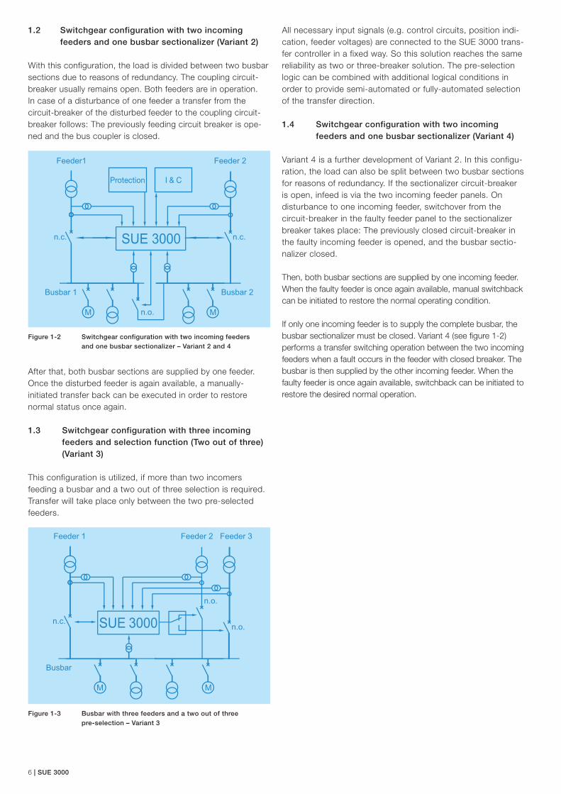
1.2 Switchgear configuration with two incoming feeders and one busbar sectionalizer (Variant 2)
With this configuration, the load is divided between two busbar sections due to reasons of redundancy. The coupling circuit-breaker usually remains open. Both feeders are in operation. In case of a disturbance of one feeder a transfer from the circuit-breaker of the disturbed feeder to the coupling circuit- breaker follows: The previously feeding circuit breaker is ope-ned and the bus coupler is closed.
After that, both busbar sections are supplied by one feeder. Once the disturbed feeder is again available, a manually- initiated transfer back can be executed in order to restore normal status once again. 1.3 Switchgear configuration with three incoming feeders and selection function (Two out of three) (Variant 3)
This configuration is utilized, if more than two incomers feeding a busbar and a two out of three selection is required. Transfer will take place only between the two pre-selected feeders.
Protection I & C
n.c.
n.o.
n.c.
M M
Busbar 2Busbar 1
Feeder1 Feeder 2
Figure 1-2 Switchgear configuration with two incoming feeders and one busbar sectionalizer – Variant 2 and 4
All necessary input signals (e.g. control circuits, position indi-cation, feeder voltages) are connected to the SUE 3000 trans-fer controller in a fixed way. So this solution reaches the same reliability as two or three-breaker solution. The pre-selection logic can be combined with additional logical conditions in order to provide semi-automated or fully-automated selection of the transfer direction.
1.4 Switchgear configuration with two incoming feeders and one busbar sectionalizer (Variant 4)
Variant 4 is a further development of Variant 2. In this configu-ration, the load can also be split between two busbar sections for reasons of redundancy. If the sectionalizer circuit-breaker is open, infeed is via the two incoming feeder panels. On disturbance to one incoming feeder, switchover from the circuit-breaker in the faulty feeder panel to the sectionalizer breaker takes place: The previously closed circuit-breaker in the faulty incoming feeder is opened, and the busbar sectio-nalizer closed.
Then, both busbar sections are supplied by one incoming feeder. When the faulty feeder is once again available, manual switchback can be initiated to restore the normal operating condition.
If only one incoming feeder is to supply the complete busbar, the busbar sectionalizer must be closed. Variant 4 (see figure 1-2) performs a transfer switching operation between the two incoming feeders when a fault occurs in the feeder with closed breaker. The busbar is then supplied by the other incoming feeder. When the faulty feeder is once again available, switchback can be initiated to restore the desired normal operation.
n.c.n.o.
M M
Busbar
Feeder 1 Feeder 2
n.o.
Feeder 3
Figure 1-3 Busbar with three feeders and a two out of three pre-selection – Variant 3
SUE 3000 | 7
The enhancement of the installation availability leads to con-siderable cost savings and to a short-term amortization of the investment: Even just one single successful transfer, which ensures the continued operation of an installation, prevents stoppage time and saves on expensive re initialization processes, can mean a complete amortization of the investment costs for the High Speed Transfer Device.
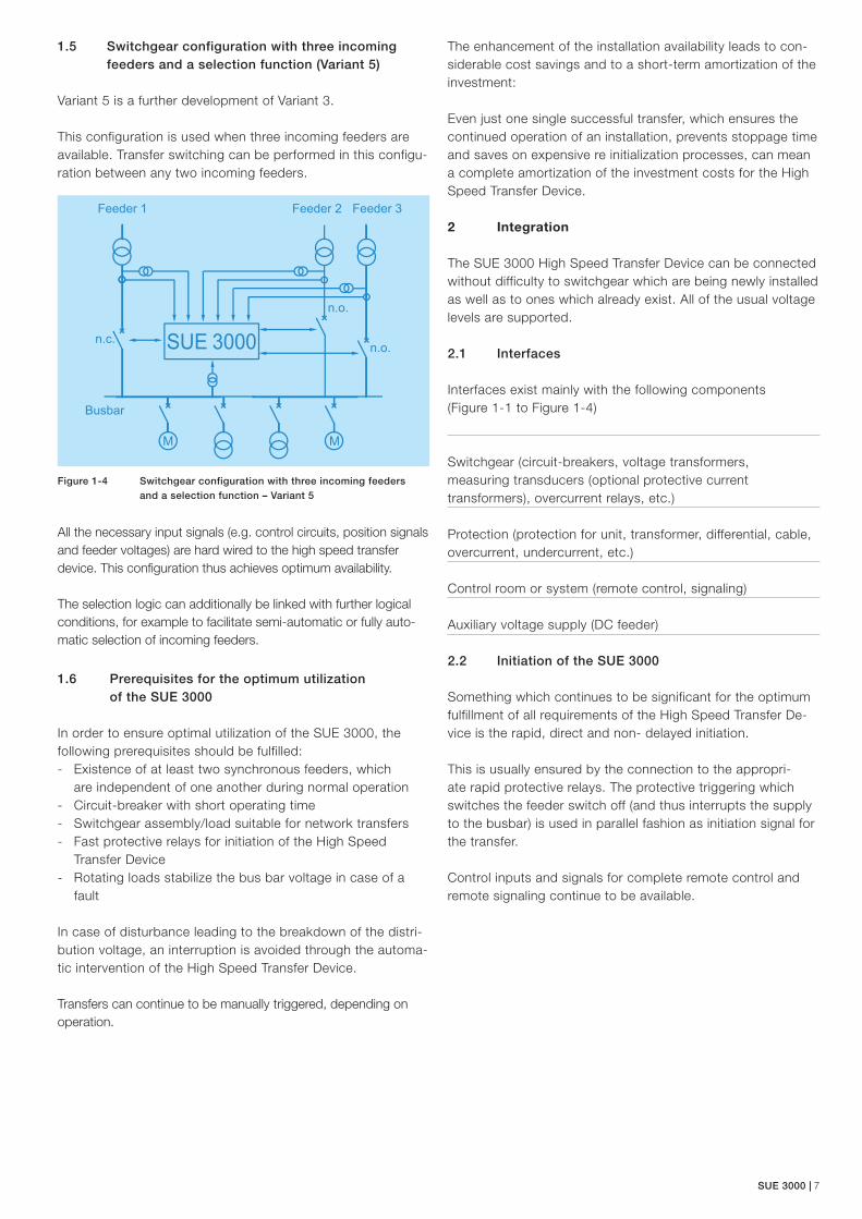
1.5 Switchgear configuration with three incoming feeders and a selection function (Variant 5)
Variant 5 is a further development of Variant 3.
This configuration is used when three incoming feeders are available. Transfer switching can be performed in this configu-ration between any two incoming feeders.
All the necessary input signals (e.g. control circuits, position signals and feeder voltages) are hard wired to the high speed transfer device. This configuration thus achieves optimum availability.
The selection logic can additionally be linked with further logical conditions, for example to facilitate semi-automatic or fully auto-matic selection of incoming feeders.
1.6 Prerequisites for the optimum utilization of the SUE 3000
In order to ensure optimal utilization of the SUE 3000, the following prerequisites should be fulfilled: - Existence of at least two synchronous feeders, which
are independent of one another during normal operation - Circuit-breaker with short operating time - Switchgear assembly/load suitable for network transfers - Fast protective relays for initiation of the High Speed
Transfer Device - Rotating loads stabilize the bus bar voltage in case of a
fault
In case of disturbance leading to the breakdown of the distri-bution voltage, an interruption is avoided through the automa-tic intervention of the High Speed Transfer Device.
Transfers can continue to be manually triggered, depending on operation.
Figure 1-4 Switchgear configuration with three incoming feeders and a selection function – Variant 5
2 Integration
The SUE 3000 High Speed Transfer Device can be connected without difficulty to switchgear which are being newly installed as well as to ones which already exist. All of the usual voltage levels are supported.
2.1 Interfaces
Interfaces exist mainly with the following components (Figure 1-1 to Figure 1-4)
Switchgear (circuit-breakers, voltage transformers, measuring transducers (optional protective current transformers), overcurrent relays, etc.)
Protection (protection for unit, transformer, differential, cable, overcurrent, undercurrent, etc.)
Control room or system (remote control, signaling)
Auxiliary voltage supply (DC feeder)
2.2 Initiation of the SUE 3000
Something which continues to be significant for the optimum fulfillment of all requirements of the High Speed Transfer De-vice is the rapid, direct and non- delayed initiation.
This is usually ensured by the connection to the appropri-ate rapid protective relays. The protective triggering which switches the feeder switch off (and thus interrupts the supply to the busbar) is used in parallel fashion as initiation signal for the transfer.
Control inputs and signals for complete remote control and remote signaling continue to be available.
n.c.n.o.
M M
Busbar
Feeder 1 Feeder 2
n.o.
Feeder 3

8 | SUE 3000
The feeder voltages, the voltage(s) of the busbar(s) as well as the currents of the feeders are connected as measurands. Transformers which perform an internal adjustment to the required extra-low voltages are integrated in the controller accordingly.
The individual components are conceived for connection to medium- and high-voltage switchgear and fulfill all the relevant requirements in this area of utilization.
Figure 3-2 SUE 3000 (Central Unit and HMI)
SUE 3000, as shown in Figure 3-2, consists of two parts, a Central Unit and a separate Human Machine Interface (HMI). The Central Unit contains the power supply, processor and analog and binary Input and Output (I/O) modules, as well as optional modules for supplementary functions.
The HMI Control Unit is a stand-alone unit with its own power supply. It can be installed on the Low Voltage (LV) compart-ment door or in a dedicated compartment close to the Central Unit. The HMI is normally used to set the parameters of the device and to operate it locally. The HMI is connected to the Central Unit by a shielded, isolated twisted pair according to the RS 485 interface.
Figure 3-3 shows an installation of a SUE 3000 in a steel sheet cubicle.
Figure 3-3 High Speed Transfer Device SUE 3000, mounted in a steel sheet cubicle
The HMI Control Unit features a back-illuminated Liquid Crys-tal Display (LCD), four status LEDs, seven push buttons, eight (virtual 32) signal LEDs, 3 LED bars for indication of analogue values and an electronic key interface.
The language of the display can be selected via the related configuration software tool, which is also used to define the functional scheme of the High Speed Transfer Device.
The left half of the LCD display is reserved for the Single Line diagram. The right half is used to display either measured or calculated analogue values or the appropriate menu or sub-menu as determined by the user. Two different electronic keys with different access rights are available.
Two fixed and one freely programmable LED bars are provided on the front of the HMI Control Unit. Each LED bar consists of ten green and two red LEDs. The third bar is user configu-rable to display any required analogue value. The red LEDs are used to indicate values above the rated value.
3 Design
The SUE 3000 is based on a real-time microprocessor sys-tem. The measurement and analog signal processing func-tions are executed by a Digital Signal Processor (DSP), while a Micro Controller (MC) is executing the logical processing and communication with binary input and output device. The Communication Processor (CP) is needed for connection to a station automation system. A block diagram of the SUE 3000 is shown in Figure 3-1.
Analogueoutput board
0/4…20mA
Analoginput card
0/4…20mA
AI 1AI 2AI 3AI 4AI 5AI 6AI 7AI 8
Analoginput
module Mainboard
Binary I/O-modules
DSP
Phase comparisonand
analog value metering Tim
e-sy
nc.
Communicationcard
RX RXCP Communication
Processor
µC
Control
CAN Eth.
Binaryinputs
Binaryoutputs
Figure 3-1 SUE 3000 block diagram (Central unit)

SUE 3000 | 9
The functions of the SUE 3000 can be tailored to the system requirements via a user-specific configuration. The user-specific configuration is loaded during commissioning. For that purpose the configuration computer, normally a personal computer running Microsoft Windows XP® or Windows 7, is connected to the optical interface on the front side of the HMI Control Unit.
The interface of the SUE 3000 to the primary process is as follows:
Analog inputs to measure current and voltage signals from instrument transformers or non conventional sensors
Binary inputs with optical couplers for the galvanic separation of the external signals to be processed
Binary outputs with conventional mechanical relays or static outputs for the control of switching devices
Optional six channel analog inputs 0 … 20 mA or 4 … 20 mA
Optional four channel analog outputs 0 … 20 mA or 4 … 20 mA
Optional connection to ABB or third party station automation system
4 Functions
SUE 3000 High speed transfer device integrates all the required functions in a single unit. This multifunctional unit also features a permanent self-monitoring function. All func-tions are designed as freely configurable software modules. Therefore, a wide range of operation requirements can be met without any problems. The versatility of the software makes it possible to use the SUE 3000 in nearly every switchboard independent on the specific application required.
4.1 Mode of operation
A significant task of the SUE 3000 is to ensure that when there is an initiation, a minimum short transfer time is achieved, the transient effects of which represent no danger to the connected users during the transfer.
For this purpose, the SUE 3000 is equipped with a fast processing logic as well as a high-precision analogue signal processing.
The device compares, on a permanent basis, the voltage of the busbar with the voltage of the stand- by feeder. The following synchronicity criteria are generated from out of the monitoring of the voltage amplitudes as well as the difference of the frequency and of the phase angle:
f < fMax Phase angle
The phase angle is determined between the voltage of the busbar and that of the stand-by feeder. The limit values for building the synchronicity criteria can be adjusted individually for leading and lagging busbars. A typical setting value is ± 20°.
Df < DfMax Frequency difference
The system determines the frequency difference between busbar voltage and the voltage of the stand-by feeder. In view of the transfer process, the frequency difference provided permits indications of the running down behavior of the con-nected consumers (e.g. of medium-voltage motors) as well as their dynamic loads. The usual factory setting is 1 Hz.
UStand-by > UMin1 Stand-by feeder voltage
The monitoring of the voltage level of the stand-by feeder is an important criterion relevant the transfer: The SUE 3000 is only then ready for transfer when an intact stand-by feeder is available. UMin1 is set at the factory to 80 % UNominal.
UBusbar > UMin2 Busbar voltage
The value of the busbar voltage plays an important role in the selection of the transfer mode: In case the busbar lies below a preset value (UMin2 - usually set to 70 % UNominal ), no fast transfer is carried out.
4.2 Permanent determination of the network conditions
An exceptionally important characteristic of the SUE 3000 High Speed Transfer Device is that the synchronicity criteria named are continuously available, e.g. that they are computed on-line by the SUE 3000.
For that reason, in case of an initiation, the transfer mode which comes under consideration is already determined and can be immediately initiated. This means that the probability of a fast transfer is considerably enhanced. Systems which wait for the instant of initiation to initiate the determination of the network status have no opportunity, when one considers the physical givens, to perform a fast transfer with minimum interruption time.
This fact clearly distinguishes the High Speed Transfer Device SUE 3000 from competing concepts.
The High Speed Transfer Device is ready for operation only when both circuit breakers to be actuated are definitely to be found in different switching statuses (plausibility monitoring) and also in operating position.

10 | SUE 3000
The current-free transfer time occurring in the first case for the users is exclusively dependent upon the difference between the operating time for closing and opening the circuit breakers concerned. These usually fall within the range of a few millisec-onds with modern circuit-breakers, therefor one can assume an uninterrupted further operation of the installation.
Figure 5-2 shows an exemplary oscillogram of a fast simulta-neous transfer with a current free transfer time (dead time) of approximately 20 ms.
1. Voltage of the busbar 2. Main feeder current 3. Stand-by feeder current 4. Total CB open time (Fault entry until CB open) 5. Dead time without current flow (simultaneous)
In the sequential transfer mode the High Speed Transfer Device waits for the OPEN position indication of the infee-ding circuit-breaker before issuing the close command to the circuit breaker of the standby feeder. SUE 3000 is constantly supervising the network environment to ensure the possibility of a fast transfer under the given conditions.
The dead time without current flow in the sequential transfer mode is strikingly longer. This results from the addition of both circuit breaker operating times plus an internal calcula-tion time. The internal calculation is of utmost importance to ensure that the required network conditions are valid before issuing the close command.
1. Voltage of the busbar 2. Main feeder current 3. Stand-by feeder current 4. Total CB open time (Fault entry until CB open) 5. Dead time without current flow (sequential)
5 Transfer modes
Decisive for the kind of transfer carried out are the network rela-tionships in the instant of initiation of the High Speed Transfer Device. Here the corresponding optimum transfer mode is selected, taking the physical interrelationships into consideration.
Four different transfer modes are available in detail:
Fast transfer: - Simultaneous control of both involved circuit-breakers (fastest mode) - Sequential control of both involved circuit-breakers (make before break)Transfer at the 1st phase coincidenceResidual voltage transferTime-operated transfer
Both fast transfer modes are the optimum transfer modes for ensuring in case of fault that only a minimum interruption of the voltage supply occurs. Should it be that the network sta-tus does not permit one of these modes, less rapid transfer modes are selected.
Figure 5-1 shows the typical decay characteristics (voltage and frequency) of a disconnected busbar and the possible closing moments.
The transfer modes are explained in brief below:
5.1 Fast transfer
The execution of fast transfers is the most preferred and most important functional principle of the SUE 3000.
A fast transfer takes place when the both the main and the stand-by feeder are within specified limit values at the mo-ment of initiation, e.g. that slip and phase angle are limited between the networks and the stand-by voltage lies above a minimum value.
Here the open and close commands to the circuit-breaker from the High Speed Transfer Device are issued either simul-taneous or sequential.
Phase angle
Busbarvoltage Residual
voltagetransfer
Transfer in1st phasecoincidence
Short-termtransfer
Long-termtransfer
TimeStart 0
0
-360°
100%
Bus
bar
vol
tage
( %
Un
)
Pha
se a
ngle
( d
egre
e)
SimultaneousSimultaneous
Sequential(Make before break)Sequential(Make before break)
Figure 5-1 Transfer mode overview
Figure 5-2 Oscillogram of a fast simultaneous transfer
1
2
3
4 5
1
2
3
4 5
Figure 5-3 Oscillogram of a sequential fast transfer

SUE 3000 | 11
1. Voltage of the busbar 2. Difference voltage between stand-by and busbar voltage 3. Main feeder current 4. Stand-by feeder current 5. Transfer duration
For a transfer at the 1st phase coincidence, project-specific details (such as, for example, circuit-breaker operating time, user characteristics, permissible frequency difference, con-nection window) must be clarified on a case-by-case basis. For this reason, the application of this functionality requires very careful engineering and a competent commissioning procedure.
Figure 5-4 Oscillogram of a transfer at the 1st phase coincidence
5.2 Transfer at the 1st phase coincidence
The transfer at the 1st phase coincidence is executed when there are no synchronized conditions present at the moment of initiation, so that no fast transfer can be carried out, due to physical reasons.
First, the previous feeder will be opened without delay. After-wards, the connected users are without power supply and run down in accordance with their specific characteristic curves.
For the connection of the stand-by feeder, a variety of points in time are possible at which an adherence to physical limit values is ensured.
For the transfer at the 1st phase coincidence, the open com-mand is issued immediately and the connection of the stand-by network takes place in the first minimum of the difference of stand-by and busbar voltage (UStand-by-UBusbar).
Connection window (dependent upon breaker cosing time and df/dt)UStand-by Stand-by feeder voltageUBusbar Busbar voltagef Angel between UStand-by and UBusbar
df/dt Angle speed between UStand-by and UBusbar (resulting from Df)
The High Speed Transfer Device determines the course of the difference voltage and the point in time of the 1st phase coincidence through anticipatory computation. In order to compensate for the installation-specific processing time (system response time, circuit breaker operating time), the close command is issued accordingly before the actual first minimum of the difference voltage occurs within a previously-defined connection window.
The conditions prevailing with a transfer at the 1st phase coin-cidence are presented in the vector diagram (Figure 5-3). The busbar voltage vector in the first minimum of the difference voltage has moved around against the fixed stand-by voltage and the angle has become zero.
1
2
3
4
5
dfdt
fUBB
UStand-by
Figure 5-3 Vector diagram of a transfer at the 1st phase coincidence
The difference voltage resulting at the moment of transfer is thereby exclusively determined by the residual voltage value of the busbar. The synchronized connection makes possible a transfer time which is exceptionally protective of the process while still being at the same time of minimum duration.

12 | SUE 3000
5.3 Residual voltage transfer
The residual voltage transfer is utilized when a connection in the 1st phase coincidence is not possible. The conditions at the instant of initiation and the opening of the previously feed-ing circuit breaker are the same as with the transfer at the 1st phase coincidence. It is solely the connection of the stand-by feeder which distinguishes itself clearly from the transfer at the 1st phase coincidence.
The connection of the stand-by feeder takes place when the voltage of the busbar has subsided to a preset, permissible value.
The connection takes place without assessment of the angle or of the difference frequency, thus in unsynchronized fashion. Because the voltage of the busbars has however reached a sufficiently low residual voltage value, the transient effects of the connection are manageable (momentary jolt, current needed for users to run up again, voltage reduction).
1. Voltage of the busbar 2. Difference voltage between stand-by and busbar voltage 3. Main feeder current 4. Stand-by feeder current 5. Transfer duration
5.4 Time-operated transfer
A time-operated transfer takes place when no other switching event could be determined before a preset time ran out during a transfer (one which did not take place on a fast basis).
This case is not expected to occur when the High Speed Transfer Device finds itself within normal operating para- meters, and it normally can occur only when there is near-simultaneous arrival of several disturbances.
For this reason, the time-operated transfer can be considered simply as a safety stage.
5.5 Supporting special functions
5.5.1 Decoupling
Fast transfers are performed in typically synchronous net-works as a general rule. Their principal of simultaneous com-mands results in short transfer times with nearly uninterrupted power supply of the transfered process. In case of a mechani-cal failure of the opening circuit breaker a short term coupling of the (synchronous) feeders occur. This is detected by the SUE 3000 and autonomous reversed to avoid an unauthorized coupling of the networks.
5.5.2 Circuit-breaker tripped transfer
This configurable function of SUE 3000 allows the monitoring of the circuit breaker position. In the case of an incoming feeder opening without a reason (e.g. Opening via mechanical interface of circuit breaker, opening via HMI) the SUE 3000 will perform a transfer if configured and READY conditions are valid.
5.5.3 Transfer mode for nonindependent networks for variant 1)
Changing network conditions create faults more often which will affect both feeders. This could result into an unready standby feeder which won‘t allow a transfer. The new transfer mode for nonindependent networks uses a programed time frame in which the standby feeder has to indicate READY condition to perform the transfer if still possible.
5.6 Summary
A very important characteristic of the SUE 3000 High Speed Transfer Device is that the selection of the transfer mode carried out takes place dynamically in connection with the respective current network relationships.
If one starts from the premise of networks which are usu-ally synchronized, then fast transfers will be carried out as a general rule.
If the networks are not synchronized at the point of time of the initiation, then no fast transfer takes place. The current-free interlude time that then arise are different, depending on the installation involved, whereby the load to be switched over determines the run-down behavior of the busbar voltage and with it the transfer duration.
The various transfer types can be selectively activated or deactivated, in a way dependent on the orientation. Thus it is ensured that, in accordance with the special requirements, the optimum transfer concept can be released for the overall installation.
Figure 5-5 Oscillogram of a residual voltage transfer in phase opposition
1
2
3
4
5

SUE 3000 | 13
6 Configuration
The SUE 3000 has at its disposal comprehensive project plan-ning and parameterization options for ensuring an optimum accommodation of assembly- specific situational details.
Each application can easily be configured by software func-tion modules, which make arbitrary definition of the following features possible:
LED’s (meaning and colors) for local indication
Single Line diagram to show the status of switching devices cooperated
Control schemes
Automation sequences
All functions of the transfer device can be specified in collabo-ration with ABB. The result of the configuration is saved and delivered together with the High Speed Transfer Device to the users.
Additional locking, releases or blocking may be required with other components, due to the many individual structuring possibilities of switchgear and the operational criteria.
These can also be flexibly and comfortably included in the planning by using the “Functional block Programming Lan-guage” (FUPLA) which offers engineers, even those who are not software experts, the opportunity of easily updating the operation of the High Speed Transfer Device.
With SUE 3000 the user has the benefit of a transfer device that is fully integrated in a true programmable controller. This flexibility is very advantageous for defining control functions for automation sequences, which can, for example, include blocking the release of specific functions, as well as required sequences for load shedding etc.
The SUE 3000 High Speed Transfer Device provides a wide range of logical functions so that each required control schemes can be configured. The range of logical functions includes:
AND logic gate
NAND logic gate
OR logic gate
NOR logic gate
XOR logic gate
Bistable and monostable flip flop
Counters
Timers
Pulse generators
Memories
6.1 Parameters
The parameters can be changed via the HMI Control Unit without using a personal computer. Additional functions can be executed with a personal computer running the configura-tion software and connected to the optical interface on the front of the HMI unit.These additional functions are:
Parameterization of the functional scheme
Read-out of the current measurement values
Read-out of the status of the binary inputs and outputs
Read-out of the fault recorder
Read-out of event lists
Viewing of the FUPLA logic I/O states (online monitoring)
(106) DI_HSTD BLOCK OVER CURRENT
(24) HSTD BLOCK CB COUPLING
D2
114
155
(107) HSTD GENERAL BLOCK
(118) HSTD BLOCK CB COIL FAIL
D7
S7
S6
(131) CB1 ISOLATED
(131) CB1 ISOLATED
≥1Zeit [ms]: 5000
(67)
(67)
76
(73) 86
(119) HSTD BLOCK SB ISOLATED
(24) HSTD BLOCK CB DECOUPLING
(118) HSTD BLOCK CB COIL FAIL
(119) HSTD BLOCK CB ISOLATED
153
(83) DI_HSTD BLOCK INITIATIONS
S Q
R Q
S Q
R Q
≥1
≥1
≥1 S QRES
QNR≥1
≥1
Figure 6-1 Exemplary logic diagram for an installation-specific configuration of the SUE 3000
14 | SUE 3000
The typical setting options are listed below and explained in brief:
Transfer types and directions The individual transfer modes can be individually activated and/or deactivated, depending on transfer direction.
Circuit-breaker command delays For optimization (reduction) of transfer interludes with simulta-neous fast transfers caused by different circuit-breaker operating time, the commands can be delayed on an indi-vidual basis.
Time settings for various functions
The time relationships within the logical control unit can be influenced by means of installation-specific project planning:
- Time-operated transfer - Decoupling time - Delay time for undervoltage initiation etc.
Limit values of analog signal processing Determination of the synchronicity criteria (angle, frequency differences, voltage inquiries)
General interventions in the functional processes of the SUE 3000
All known installation-specific details are taken into account within the framework of the installation project planning and a customer-specific parameter setting is undertaken.
The configuration is stored in nonvolatile RAM (NVRAM). It could be modified by the customer without difficulty by means of the configuration tool contained in the scope of supply.
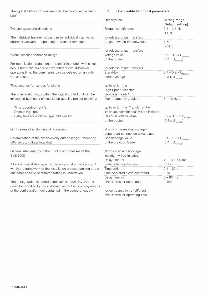
6.2 Changeable functional parameters
Description Setting range (Default setting)Frequency difference 0.5 – 2.5 Hz (1 Hz) for release of fast transfersAngle between the networks ± 50° (± 20°) for release of fast transfersVoltage value 0.6 – 0.8 x UNominal
of the busbar (0.7 x UNominal )
for release of fast transfersStand-by 0.7 – 0.9 x UNominal
feeder voltage (0.8 x UNominal )
up to which the High Speed Transfer Device is “ready”Max. frequency gradient 5 – 40 Hz/s
up to which the “Transfer at the 1st phase coincidence” will be initiatedResidual voltage value 0.2 – 0.55 x UNominal
of the busbar (0.4 x UNominal )
at which the residual voltage- dependent connection takes placeUndervoltage value 0.1 – 1.2 x UNominal
of the previous feeder (0.7 x UNominal)
at which an undervoltage initiation will be initiatedDelay time for 40 – 30,000 ms
undervoltage initiations (0.1 s)Time until 0.1 – 60 s
time-operated close command (2 s)Delay time for 0 – 60 ms
circuit-breaker commands (0 ms) for compensation of different circuit-breaker operating time

SUE 3000 | 15
6.3 Fault recording
The High Speed Transfer Device SUE 3000 is equipped with a fault recorder module, which records and encodes analog and binary data. The number of recorded data channels depends on the initial configuration. Up to eight signals of the analog channels and 32 binary signals can be recorded. The analog input signals are recorded with a sampling rate of 1.2 kHz for a period of at least 1000 ms to a maximum of 5000 ms. The recording time is a combination of pre- and post trigger time. The records are saved using a typical ring buffer process, i.e. the oldest record is always overwritten with a new one (FIFO characteristics). The number of saved fault records depends on the record time. For example, a maximum of 5 fault re-cords can be saved with a recording time of 1000 ms. Fault records can be exported and converted by the configuration software. The transfer of records can be done also via the interbay bus.
With this useful feature recorded transfers could be analyzed and e.g. project specific parameters could be verified. 7 Operation
A wide range of functions can be controlled and operated using the simple, user-friendly interface on the HMI Control Unit. This user-friendly interface is shown in the following Figure 7-1.
The HMI consists of the following features:
7.1 LCD (Liquid crystal display)
The back-illuminated LC display of the HMI provides a graphi-cal display of the switching devices in the switchbay con-trolled by the SUE 3000. The intensity and the duration of the illumination can be set as required. The Single Line diagram shows the current status of all the switching devices. The right half of the LC display is for plain text, such as measure-ment values, main menu and submenus descriptions, protec-tion signals and event recording.
On the LC display, the following can be shown:
Up to eight switching device icons
Various icons for motors, transformers, sensors, transducers
A maximum of 40 individual lines
7.2 Status indication
Four system LEDs, describe in the following chapters, indicate the status of the SUE 3000.
7.2.1 Operational status
On the HMI front panel, the operational status is called “Ready” and is displayed by a green LED. The unit is not operational when this LED is off, and this occurs for example during the downloading of the configuration or if a fault condi-tion is detected in the Central Unit.
7.2.2 Communication status
If the SUE 3000 is to be connected to a station automation system, the appropriate communications board is required. In this case a green LED is used to indicate the correct opera-tional status of this optional board. The LED color changes to red if a communication failure has occurred.
7.2.3 Alarm indication
Several arbitrary alarm conditions can be defined and config-ured by the user. If one of these conditions is fulfilled, the red LED will be on.
7.2.4 Interlocking status
- Not used -
Figure 7-1 HMI as Control Unit

16 | SUE 3000
7.3 LED indication
7.3.1 Freely programmable LEDs
Eight freely programmable, three color LED’s are provided for local indication. The number of LED display options can be quadrupled through the menu structure. As a result, a total of 32 indication options are available for status indication regard-ing control, monitoring and supervision functions.
Status dependent LED texts are provided.
7.3.2 Bar displays
Three LED bars are provided for showing the measurement values. Two of them are used to display the current measure-ments of the feeding sources (if required). The third bar is freely configurable. Each bar consists of ten green and two red LEDs. The nominal values of each LED bar, which corresponds to the ten green LEDs are defined by the configuration software. If the measurement values exceed the rated values, the red LEDs will get illuminated indicating an overload situation.
7.4 Control push buttons
The control push buttons are used for operation of the High Speed Transfer Device during local control. A total of seven push buttons are available, three for commanding the primary equipment (if required) and four for browsing the display and operating the SUE 3000.
7.5 Function key
The function key button allows e.g. to start an inside the FUPLA implementated function or a control command.
7.6 Electronic key
Two different electronic keys are provided. One key can only be used for the parameterization of the High Speed Transfer Device. The other one is for control modes selection: local, remote or local/remote. By using these two keys a certain separation between parameterization and control operation can be achieved. The sensor for recognizing which electronic key has been used is located on the front panel of the HMI Control.
The following displays and operating functions are provided on the front of the device:
Switching the SUE 3000 On/Off
Manual initiation
Single-line display of the circuit board configuration
- Position monitoring of the circuit-breakers - Voltages of the feeders and of the busbars - Operating currents of the feeders - Status of the High Speed Transfer Device - Phase angle between the feeders
Alarm LEDs with clear-text lettering and acknowledgment function
Off/Local/remote-selection with key switches
Operation/set-selection with key switches
Furthermore, the High Speed Transfer Device can be operated completely by remote control. Manual triggering are executed from the control room and disturbance-specific, automatic ini-tiations are triggered independently by the protection mecha-nisms. Status and disturbance messages can be signaled to the control room and/or to a process control system.
8 Testing, quality control
The thoroughly consistent application of the ABB Quality and Environmental Management System in conformity with EN ISO 9001 and EN ISO 14001 guarantees a high qual-ity standard during the course of the entire engineering and manufacturing procedure, all the way up to the delivery of the devices.
In addition to the execution of the one-time type tests, every system is submitted to an isolation testing and a functional examination at the factory prior to delivery. Project-specific solutions can be tested using switchgear simulation models.
9 Operational safety
During the development of the SUE 3000 High Speed Transfer Device, special emphasis was placed on the realization of a maximum operational safety.
A large number of internal monitoring functions, but also of diagnostics transcending individual devices, such as perma-nent coil monitoring as well as running time monitoring of the circuit-breakers, ensured the highest degree of safety.
The planning, production and application know-how gathered at ABB over the course of decades for High Speed Transfer Devices has been thoroughly incorporated into the design of the SUE 3000. The device represents the current state of the technology of automatic transfer schemes with conventional circuit-breakers.

SUE 3000 | 17
10 Technical data
10.1 Response time
Response time is the time between protective initiation of the High Speed Transfer Device SUE 3000 and the command be-ing issued to the circuit breakers involved.
Response time with solid state (Static I/O board) < 2 ms
10.2 Current and voltage transformer
10.2.1 Rated current
Rated current IN 1 A or 5 A
Rated voltage UN 100 V ... 125 V
Rated frequency fN 50 Hz / 60 Hz
10.2.2 Thermal load capacity
Current path 250 IN (peak value) 100 IN (dyn.) für 1 s 4 IN continuous
Voltage path 2 UN/√3 continuous
10.2.3 Consumption
Current path 0.1 VA with IN
Voltage path 0.25 VA with UN
10.3 Binary inputs and outputs
In order to achieve the operations of the primary equipment and establish conventional (parallel) communication, the SUE 3000 is equipped with binary I/O boards.
The inputs of the binary signals are isolated by an opto- coupler. Each input has a minimum fixed filter time of 1 ms.
However, in order to achieve the required fast operating time for high speed transfer applications, static outputs have to be installed. A maximum of 3 binary I/O board can be installed.
10.3.1 Binary I/O board with static relays
Number of inputs 14 per board
Input voltage 48 … 265 V DC / 110 … 265 V DC (Threshold 35 V DC or 75 V DC)
Number of power outputs 2 per board
Operating voltage 48 … 265 V DC
Making current 70 A (t ≤ 10 ms)
Load current 12 A (t ≤ 30 s)
Number of other power outputs 4 per board
Operating voltage 48 … 265 V DC
Making current 16 A (t ≤ 10 ms)
Load current 10 A (t ≤ 30 s)
Number of signal outputs 2 per board
Operating voltage 48 … 265 V DC
Making current 1 A (t ≤ 10 ms)
Load current 0.3 A (t ≤ 30 s)
Number of watchdog outputs (WD) 1 per board
Operating voltage 48 … 265 V DC
Max. current 0.3 A
Total inputs 14 per board
Total outputs 9 per board (8 freely configurable)
Number of power outputs 2 with coil supervision (Coil OK if RCoil < 10 kΩ)

18 | SUE 3000
10.4 Communication interfaces
10.4.1 HMI control unit
Optical/electrical standard interface RS 232 to the Notebook PC (at the front)
Electrical isolated standard interface RS 485 to the Central Unit (at the rear)
10.4.2 Central unit
Electrical isolated standard interface RS 485 to the HMI
Electrical standard service interface RS 232 for updating the firmware
Input for time synchronization (optional, the supported protocol is IRIG, format B000, B002, B003). Glass fiber Wavelength: 820 nm Max. distance: 1500 m Connector type: ST
10.5 Analog input board (optional)
0 … 20 mA or 4 … 20 mA (six channels)
10.6 Analog output board (optional)
0 … 20 mA or 4 … 20 mA (four channels)
10.7 Communication to a station automation system (optional)
IEC 61850-8-1 * electrical interface with two RJ45 connectors or optical inter-face with two pair LC connectors for glass fiber (multi-mode)
SPA optical plastic fiber interface with snap-in type connector; or glass fiber (multi mode) with F-SMA or ST connectors
IEC 60870-5-103 with extension according to VDN guidelines for control, glass fiber (multi-mode) optical interface with ST connectors
ModBUS RTU electrical interface with two galvanically insulated RS-485 ports or optical interface with four standard ST connectors for glass
ModBUS TCP Electrical RJ-45 connector or optical LC connector for glas fiber (multi mode) on Ethernet board
Ethernet interface Standard RJ45 connector on the core module
Profibus DP electrical RS 485 interface (with adapter)
* IEC 61850 communication hardware and firmware is similar to the REF542plus platform version
10.8 Power supply
10.8.1 Central unit
Rated voltage 48 … 220 V DC (-15%, +10%)
Power consumption ≤ 40 W
Inrush current 10 A peak value (for 200 ms)
Admissible ripple < 10 %
10.8.2 HMI control unit
Rated voltage 48 … 220 V DC (-15%, +10%)
Power consumption ≤ 6 W
Admissible ripple < 10%
10.9 Environmental conditions
Ambient operation temperature -10 .. +55°C
Ambient transport and storage temperature -25 .. +70°C
Ambient humidity Upt o 95% without condensation
Altitude < 1000 m above sea level
10.10 Protection degree
10.10.1 Central unit
Case IP20
10.10.2 HMI control unit
Front IP44
Rear IP20

SUE 3000 | 19
11 Housing
11.1 Abmessungen
The SUE 3000 housing for the Central Unit is made from sheet aluminum. Its exterior is both to protect the housing against corrosion and to gain the shielding against EMC disturbances. In the housing could be integrated up to three I/O boards, an optional communication board and an analogue board.
Figure 11-2 Dimension drawing of the central unitFigure 11-1 Dimension of the HMI control unit
11.2 Available design
The SUE 3000 High Speed Transfer Device can be supplied in a choice of 2 different mechanical models.
Single control unit for loose installation in a low-voltage com-partment of a switchbay
Installed ready for connection in a steel-sheet cabinet fully enclosed in steel sheet cubicles including all required devices such as MCBs, terminals, relays, etc.

20 | SUE 3000
12.3 Isolation
Voltage test according to IEC 60255-5 with 2 kV RMS, 50 Hz during 1 min
Impulse voltage withstand test according to IEC 60255-5 with 5 kV 1.2/50 µs.
12.4 Mechanical properties
Vibration test according to IEC 60255-21-1
Earthquake test according to IEEE 693
12.5 Environmental conditions
Cold test according to IEC 60068-2-1
Dry heat test according to IEC 60068-2-2
Damp Heat and Cycling test according to IEC 60068-2-30
12.6 RoHS compliance
Complies with RoHS directive 2002/95/EC
12.7 IEC 61850-8-1 communication
KEMA IEC 61850 Certificate Level A1 - based on REF542plus Feeder Terminal with IEC 61850 interface (1MRS756326)
12 Type test
12.1 Functional test
All relevant tests are performed according to IEC 60255 stan-dard series and the test specification for the testing of the transfer functions.
12.2 EMC
The SUE 3000 High Speed Transfer Device fulfils all important national and international EMC regulations. All relevant tests are according to the following standard series:
Interference suppression according to EN 55022 respectively IEC CISPR 11, Group 1
Immunity to electrostatic discharge according to IEC 61000-4-2, level 3
Immunity to radiated electromagnetic energy according to IEC 61000-4-3, level 3
Electrical fast transient or burst according to IEC 61000-4-4, level 3
Surge immunity tests according to IEC 61000-4-5, level 3
Immunity to conducted disturbances induced by radio frequency fields according to IEC 61000-4-6, level 3
Power frequency magnetic field immunity according to IEC 61000-4-8, level 5
Pulse magnetic field immunity according to IEC 61000-4-9, level 5
Damped oscillatory magnetic field immunity according to IEC 61000-4-10, level 5
Oscillatory waves immunity according to IEC 61000-4-12, level 3
Oscillatory waves immunity in the range from 0 to 150 kHz according to IEC 61000-4-16, level 3
Ripple on DC input power port immunity according to IEC 61000-4-17, level 3
Voltage dips, short interruptions and voltage variations on DC input power ports per IEC 61000-4-29, 50 ms

SUE 3000 | 21

22 | SUE 3000

SUE 3000 | 23

PG
609
gb
prin
ted
in G
erm
any
(06.
16 -
500
-AM
C)ABB AG
Calor Emag Medium Voltage ProductsOberhausener Strasse 33 40472 Ratingen, Germany Phone: +49 2102 12-0 Fax: +49 2102 12-17 77 E-mail: [email protected] www.abb.com/mediumvoltage
Contact
Note:We reserve the right to make technical changes or modify the contents of this document without prior notice. With regard to purchase orders, the agreed particulars shall prevail. ABB AG does not accept any responsibility whatsoever for potential errors or possible lack of information in this document.
We reserve all rights in this document and in the subject matter and illustrations contained therein. Any reproduction, disclosure to third parties or utilization of its contents – in whole or in parts – is forbidden without prior written consent of ABB AG.
Copyright© 2016 ABBAll rights reserved


![€¦ · Web view2009. 4. 23. · [Cr2O72-] Reverse Rate. A. increases increases. B. increases decreases. C. decreases decreases. D. decreases increases. 31. A small amount of H2SO4](https://img.pdfslide.us/doc/110x75/608f2c47b9e3f5096f2e5efc/web-view-2009-4-23-cr2o72-reverse-rate-a-increases-increases-b-increases.jpg)